WO2021220941A1 - 振動構造、振動装置および触覚提示装置 - Google Patents
振動構造、振動装置および触覚提示装置 Download PDFInfo
- Publication number
- WO2021220941A1 WO2021220941A1 PCT/JP2021/016357 JP2021016357W WO2021220941A1 WO 2021220941 A1 WO2021220941 A1 WO 2021220941A1 JP 2021016357 W JP2021016357 W JP 2021016357W WO 2021220941 A1 WO2021220941 A1 WO 2021220941A1
- Authority
- WO
- WIPO (PCT)
- Prior art keywords
- vibrating
- piezoelectric
- plate
- connecting member
- shaped portion
- Prior art date
- Legal status (The legal status is an assumption and is not a legal conclusion. Google has not performed a legal analysis and makes no representation as to the accuracy of the status listed.)
- Ceased
Links
Images


Classifications
-
- B—PERFORMING OPERATIONS; TRANSPORTING
- B06—GENERATING OR TRANSMITTING MECHANICAL VIBRATIONS IN GENERAL
- B06B—METHODS OR APPARATUS FOR GENERATING OR TRANSMITTING MECHANICAL VIBRATIONS OF INFRASONIC, SONIC, OR ULTRASONIC FREQUENCY, e.g. FOR PERFORMING MECHANICAL WORK IN GENERAL
- B06B1/00—Methods or apparatus for generating mechanical vibrations of infrasonic, sonic, or ultrasonic frequency
- B06B1/02—Methods or apparatus for generating mechanical vibrations of infrasonic, sonic, or ultrasonic frequency making use of electrical energy
- B06B1/06—Methods or apparatus for generating mechanical vibrations of infrasonic, sonic, or ultrasonic frequency making use of electrical energy operating with piezoelectric effect or with electrostriction
- B06B1/0644—Methods or apparatus for generating mechanical vibrations of infrasonic, sonic, or ultrasonic frequency making use of electrical energy operating with piezoelectric effect or with electrostriction using a single piezoelectric element
-
- B—PERFORMING OPERATIONS; TRANSPORTING
- B06—GENERATING OR TRANSMITTING MECHANICAL VIBRATIONS IN GENERAL
- B06B—METHODS OR APPARATUS FOR GENERATING OR TRANSMITTING MECHANICAL VIBRATIONS OF INFRASONIC, SONIC, OR ULTRASONIC FREQUENCY, e.g. FOR PERFORMING MECHANICAL WORK IN GENERAL
- B06B1/00—Methods or apparatus for generating mechanical vibrations of infrasonic, sonic, or ultrasonic frequency
- B06B1/02—Methods or apparatus for generating mechanical vibrations of infrasonic, sonic, or ultrasonic frequency making use of electrical energy
- B06B1/06—Methods or apparatus for generating mechanical vibrations of infrasonic, sonic, or ultrasonic frequency making use of electrical energy operating with piezoelectric effect or with electrostriction
-
- B—PERFORMING OPERATIONS; TRANSPORTING
- B06—GENERATING OR TRANSMITTING MECHANICAL VIBRATIONS IN GENERAL
- B06B—METHODS OR APPARATUS FOR GENERATING OR TRANSMITTING MECHANICAL VIBRATIONS OF INFRASONIC, SONIC, OR ULTRASONIC FREQUENCY, e.g. FOR PERFORMING MECHANICAL WORK IN GENERAL
- B06B1/00—Methods or apparatus for generating mechanical vibrations of infrasonic, sonic, or ultrasonic frequency
- B06B1/02—Methods or apparatus for generating mechanical vibrations of infrasonic, sonic, or ultrasonic frequency making use of electrical energy
- B06B1/0207—Driving circuits
-
- B—PERFORMING OPERATIONS; TRANSPORTING
- B06—GENERATING OR TRANSMITTING MECHANICAL VIBRATIONS IN GENERAL
- B06B—METHODS OR APPARATUS FOR GENERATING OR TRANSMITTING MECHANICAL VIBRATIONS OF INFRASONIC, SONIC, OR ULTRASONIC FREQUENCY, e.g. FOR PERFORMING MECHANICAL WORK IN GENERAL
- B06B1/00—Methods or apparatus for generating mechanical vibrations of infrasonic, sonic, or ultrasonic frequency
- B06B1/02—Methods or apparatus for generating mechanical vibrations of infrasonic, sonic, or ultrasonic frequency making use of electrical energy
- B06B1/06—Methods or apparatus for generating mechanical vibrations of infrasonic, sonic, or ultrasonic frequency making use of electrical energy operating with piezoelectric effect or with electrostriction
- B06B1/0644—Methods or apparatus for generating mechanical vibrations of infrasonic, sonic, or ultrasonic frequency making use of electrical energy operating with piezoelectric effect or with electrostriction using a single piezoelectric element
- B06B1/0655—Methods or apparatus for generating mechanical vibrations of infrasonic, sonic, or ultrasonic frequency making use of electrical energy operating with piezoelectric effect or with electrostriction using a single piezoelectric element of cylindrical shape
-
- G—PHYSICS
- G06—COMPUTING OR CALCULATING; COUNTING
- G06F—ELECTRIC DIGITAL DATA PROCESSING
- G06F3/00—Input arrangements for transferring data to be processed into a form capable of being handled by the computer; Output arrangements for transferring data from processing unit to output unit, e.g. interface arrangements
- G06F3/01—Input arrangements or combined input and output arrangements for interaction between user and computer
- G06F3/016—Input arrangements with force or tactile feedback as computer generated output to the user
-
- G—PHYSICS
- G06—COMPUTING OR CALCULATING; COUNTING
- G06F—ELECTRIC DIGITAL DATA PROCESSING
- G06F3/00—Input arrangements for transferring data to be processed into a form capable of being handled by the computer; Output arrangements for transferring data from processing unit to output unit, e.g. interface arrangements
- G06F3/01—Input arrangements or combined input and output arrangements for interaction between user and computer
- G06F3/03—Arrangements for converting the position or the displacement of a member into a coded form
- G06F3/041—Digitisers, e.g. for touch screens or touch pads, characterised by the transducing means
-
- B—PERFORMING OPERATIONS; TRANSPORTING
- B06—GENERATING OR TRANSMITTING MECHANICAL VIBRATIONS IN GENERAL
- B06B—METHODS OR APPARATUS FOR GENERATING OR TRANSMITTING MECHANICAL VIBRATIONS OF INFRASONIC, SONIC, OR ULTRASONIC FREQUENCY, e.g. FOR PERFORMING MECHANICAL WORK IN GENERAL
- B06B2201/00—Indexing scheme associated with B06B1/0207 for details covered by B06B1/0207 but not provided for in any of its subgroups
- B06B2201/50—Application to a particular transducer type
- B06B2201/55—Piezoelectric transducer
Definitions
- the present invention relates to a vibrating structure, a vibrating device using the vibrating structure, and a tactile presentation device using the vibrating device.
- the device of the present invention can be used as a device for removing and transporting droplets, powder, and the like.
- the touch panel which is an input device that allows the user to operate the device by pressing the display on the screen, is a tactile presentation device that makes the user feel that the touch panel is pressed by transmitting vibration when the user presses the touch panel. May be provided.
- the vibration structure for generating vibration in the tactile presentation device the vibration structure described in International Publication No. 2019/013164 (Patent Document 1) can be mentioned.
- the vibrating structure described in Patent Document 1 includes a film (hereinafter referred to as a piezoelectric member) that deforms in the plane direction when a voltage is applied, and a vibrating member including a frame-shaped portion, a vibrating portion, and a supporting portion. , With connecting members.
- the frame-shaped portion has an opening, and a part of the piezoelectric member is connected.
- the vibrating portion is arranged inside the opening, and another part of the piezoelectric member is connected to the vibrating portion, and the piezoelectric member deforms in the surface direction to vibrate in the surface direction.
- the support portion supports the vibrating portion in a frame-shaped portion.
- the connecting member connects the piezoelectric member and the frame-shaped portion, and the piezoelectric member and the vibrating portion, respectively.
- the vibration structure described in Patent Document 1 is connected so that a part of the piezoelectric member and the frame-shaped portion overlap each other. That is, when the tactile presentation device incorporating the vibration structure receives an impact, tensile stress is likely to be generated in the piezoelectric member due to the impact. Therefore, the piezoelectric member may be damaged and the tactile presentation device may not operate normally.
- piezoelectric ceramics that are easily damaged by impact are used as the piezoelectric member, or when a resin piezoelectric film is used but it is fixed with tensile stress inherent, it is fixed due to the generation of tensile stress due to impact. This challenge becomes prominent when it is fragile.
- An object of the present invention is to provide a vibration structure capable of suppressing damage to a piezoelectric member when subjected to an impact, a vibration device using the vibration device, and a tactile presentation device.
- the vibrating structure includes a vibrating member including a frame-shaped portion, a vibrating portion, and a supporting portion, a piezoelectric member, a first connecting member, and a second connecting member.
- the frame-shaped portion has a first opening.
- the vibrating portion is located inside the first opening and has a second opening.
- the support portion supports the vibrating portion in the frame-shaped portion.
- the piezoelectric member is arranged inside the second opening, has a first end portion and a second end portion, and when a voltage is applied, the first end portion and the second end portion are separated from each other. It expands and contracts in the first direction of tying.
- the first connecting member connects the first end portion of the piezoelectric member and the frame-shaped portion.
- the second connecting member connects the second end portion of the piezoelectric member and the vibrating portion. And at least the first connecting member is an elastic body.
- the present invention is also directed to a vibrating device.
- the vibrating device according to the present invention includes the vibrating structure according to the present invention and a drive circuit for applying a voltage to the piezoelectric member included in the vibrating structure.
- the present invention is also directed to a tactile presentation device.
- the tactile presentation device according to the present invention includes a vibration device according to the present invention and a pressure detection unit that detects pressure on the vibration unit included in the vibration structure.
- the vibration structure according to the present invention can suppress the generation of tensile stress in the piezoelectric member when it receives an impact by elastic deformation of the first connecting member which is an elastic body. Therefore, it is possible to suppress damage to the piezoelectric member when it receives an impact. Further, since the vibration device according to the present invention uses the vibration structure according to the present invention, it is possible to suppress a failure when receiving an impact. Further, since the tactile presentation device according to the present invention uses the vibration device according to the present invention, the user can feel the tactile sensation even after receiving an impact. When this device is used as a device for removing and transporting droplets, powders, etc., it can similarly maintain its function even after being impacted.
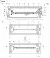
- FIG. 1A is a bird's-eye view of the vibration structure 100, which is a schematic form of the vibration structure according to the present invention.
- FIG. 1 (B) shows the connection between the piezoelectric member 2 and the first connecting member 3, and the voltage applying member 5 and the first connecting member 3, the X1-X1 line shown in FIG. 1 (A). It is a partial cross-sectional view of the vibration structure 100 cut by the plane including.
- FIG. 2A is a plan view of the vibrating structure 100 in a state before being impacted.
- the vibrating structure 100 has a first vibration structure 100 so that the vibrating portion 1b is displaced from the first portion 3a of the first connecting member 3 toward the first portion 4a of the second connecting member 4.
- the vibrating structure 100 has a first vibration structure 100 so that the vibrating portion 1b is displaced from the first portion 4a of the second connecting member 4 toward the first portion 3a of the first connecting member 3. It is a top view of the state which received the impact along the direction D1 of 1. It is a bird's-eye view of the vibration structure 100A which is the 1st modification of the vibration structure 100. It is a bird's-eye view of the vibration structure 100B which is the 2nd modification of the vibration structure 100.
- FIG. 5A is a bird's-eye view of the vibration structure 100C, which is a third modification of the vibration structure 100.
- FIG. 6A is a bird's-eye view of the vibration structure 100D, which is a fourth modification of the vibration structure 100.
- FIG. 6B the second plate-shaped portion 3a 2 of the first portion 3a of the first connecting member 3 is in the first direction due to the impact received by the vibration structure 100D along the first direction D1.
- FIG. 6E shows bending to D1.
- FIG. 9A is a bird's-eye view of the vibration structure 100G, which is a seventh modification of the vibration structure 100.
- FIG. 9B shows expansion and contraction of the bent portion of each support portion and expansion and contraction of the bent portion of the second plate-shaped portion 3a 2 of each connecting member due to the impact received by the vibration structure 100G along the second direction D2. It is a plan view which shows the deformation of the 1st part 3a of the 1st connection member 3. It is a bird's-eye view of the vibration structure 100H which is the 8th modification of the vibration structure 100.
- FIG. 9A is a bird's-eye view of the vibration structure 100G, which is a seventh modification of the vibration structure 100.
- FIG. 9B shows expansion and contraction of the bent portion of each support portion and expansion and contraction of the bent portion of the second plate-shaped portion 3a 2 of each connecting member due to the impact received by the vibration structure 100G along the second direction D2. It is a plan view which shows the deformation of the 1st part 3a
- 11A is a bird's-eye view of the vibration structure 100I, which is a ninth modification of the vibration structure 100.
- 11 (B) is a cross-sectional view taken along the line of the vibrating structure 100I cut along the plane including the X2-X2 line shown in FIG. 11 (A). It is a bird's-eye view of the vibration structure 100J which is a tenth modification of the vibration structure 100. It is an exploded bird's-eye view of the vibration structure 100J. It is a bird's-eye view of the vibration structure 100K which is the eleventh modification of the vibration structure 100. It is an exploded bird's-eye view of a vibration structure 100K.
- FIG. 1A is a bird's-eye view of the vibration structure 100.
- FIG. 1 (B) shows the connection between the piezoelectric member 2 and the first connecting member 3, and the voltage applying member 5 and the first connecting member 3, the X1-X1 line shown in FIG. 1 (A). It is a partial cross-sectional view of the vibration structure 100 cut by the plane including.
- the vibration structure 100 includes a vibration member 1, a piezoelectric member 2, a first connecting member 3, and a second connecting member 4.
- the first connecting member 3 includes a first portion 3a and a second portion 3b.
- the second connecting member 4 includes a first portion 4a and a second portion 4b.
- the vibrating member 1 includes a frame-shaped portion 1a, a vibrating portion 1b, and a support portion 1c to 1f.
- the vibration structure 100 is connected to a circuit or device that applies a voltage to the piezoelectric member 2 such as a drive circuit 200 (not shown in FIG. 1) described later, for example, via a voltage application member 5.
- the vibrating member 1 has a first main surface and a second main surface facing back from the first main surface.
- the frame-shaped portion 1a of the vibrating member 1 has a first opening A1.
- the vibrating portion 1b is a plate-shaped member having a rectangular main portion and projecting portions on opposite short sides, and is arranged inside the first opening A1.
- the vibrating portion 1b is formed with a rectangular second opening A2 having a long axis along the expansion / contraction direction of the piezoelectric member 2, which will be described later in a plan view.
- the second opening A2 communicates with the first opening A1.
- the support portions 1c to 1f are strip-shaped extending in a direction orthogonal to the expansion / contraction direction of the piezoelectric member 2 described below (second direction D2 described later), and each of the support portions 1c to 1f has a frame-shaped portion 1a and a protruding portion of the vibrating portion 1b. By connecting, the vibrating portion 1b is supported by the frame-shaped portion 1a.
- the frame-shaped portion 1a, the vibration portion 1b, and the support portions 1c to 1f of the vibration member 1 are formed of the same member.
- a fiber-reinforced plastic material such as an acrylic resin, polyethylene terephthalate, polycarbonate, or glass epoxy composite material, metal, glass, or the like can be used.
- a metal stainless steel, tungsten alloy, titanium alloy and the like are preferable.
- a substrate material for circuit wiring may be used. In this case, the portion related to the electrical wiring can be simplified.
- the frame-shaped portion 1a, the vibrating portion 1b, and the support portions 1c to 1f can be formed by punching one rectangular plate member so that these portions remain.
- the frame-shaped portion 1a, the vibrating portion 1b, and the support portions 1c to 1f can be easily formed. Further, when the same member is punched, it becomes easy to match the natural vibration cycles of the plurality of support portions 1c to 1f to the same. Therefore, it is possible to reduce the vibration variation when the vibrating portion 1b is vibrated.
- the frame-shaped portion 1a, the vibrating portion 1b, and the support portions 1c to 1f do not have to be formed of the same member, and may be different members.
- the vibration state of the vibrating portion 1b can be adjusted by changing the material of each supporting portion from the materials of the frame-shaped portion 1a and the vibrating portion 1b. can.
- the vibration of the vibrating portion 1b can be increased while the voltage applied to the piezoelectric member 2 is reduced.
- the piezoelectric member 2 is formed on a prismatic piezoelectric element 2a, a first electrode 2b provided on the first main surface of the piezoelectric element 2a, and a second main surface facing the first main surface. It includes a second electrode 2c and has a first end and a second end (see FIG. 1B).
- the piezoelectric member 2 is arranged inside the second opening A2, and a voltage is applied between the above electrodes to connect the first end portion and the second end portion in the first direction D1. Expands and contracts.
- the first direction D1 which is the expansion / contraction direction of the piezoelectric member 2 and the long axis of the rectangular second opening A2 are parallel to each other.
- a piezoelectric ceramic material exhibiting a large inverse piezoelectric effect such as lead zirconate titanate and lead-free piezoelectric ceramics such as niobium-based piezoelectric ceramics can be used. In this case, the vibration of the vibrating portion 1b can be increased.
- the voltage is applied between the electrodes of the piezoelectric member 2 in the vibration structure 100 via the first portion 3a and the second portion 3b of the voltage application member 5 to the first connecting member 3, which will be described later.
- the voltage may be applied from the voltage applying member 5 via another wiring without passing through the first portion 3a and the second portion 3b of the first connecting member 3.
- the voltage may be applied not through the voltage applying member 5 but through another wiring and the first portion 3a and the second portion 3b of the first connecting member 3.
- the voltage may be applied not through the first portion 3a and the second portion 3b of the voltage applying member 5, the first connecting member 3, but through another wiring.
- the piezoelectric element 2a does not have to be a prismatic shape, and may be a columnar shape other than the prismatic shape such as a columnar shape, or may be a plate shape or a film shape.
- a resin piezoelectric film such as polyvinylidene fluoride, L-type polylactic acid, and D-type polylactic acid can be used as the material of the piezoelectric element 2a.
- the piezoelectric member 2 is a resin piezoelectric film as described above, it is preferable that the piezoelectric member 2 is connected to each connecting member described later in a state in which tensile stress is inherent, that is, in a state where tension is applied.
- the resin piezoelectric film may be connected to each connecting member so that the tensile stress is generated only when the film is contracted.
- the piezoelectric member 2 is connected to the frame-shaped portion 1a of the vibrating member 1 by the first portion 3a and the second portion 3b of the first connecting member 3, and is connected to the frame-shaped portion 1a of the vibrating member 1.
- the first portion 4a and the second portion 4b of 4 are connected to the vibrating portion 1b of the vibrating member 1.
- Each portion of the first connecting member 3 and the second connecting member 4 has a strip shape extending along the first direction D1, which is the expansion / contraction direction of the piezoelectric member 2.
- the first portion 3a of the first connecting member 3 is an elastic body, and is a first end portion of a first electrode 2b provided on a first main surface of the piezoelectric member 2 and a frame-shaped portion 1a.
- the main surface of No. 1 is connected to the main surface of No. 1 via a voltage application member 5.
- the first portion 3a of the first connecting member 3 can serve as a voltage supply path to the piezoelectric member 2.
- the second portion 3b of the first connecting member 3 and the first portion 4a and the second portion 4b of the second connecting member 4 also have the same elasticity as the first portion 3a of the first connecting member 3.
- the second portion 3b of the first connecting member 3 includes the first end portion of the second electrode 2c provided on the second main surface of the piezoelectric member 2 and the second main surface of the frame-shaped portion 1a. Is connected to the first portion 3a of the first connecting member 3 while facing the first portion 3a via the voltage applying member 5.
- the second portion 3b of the first connecting member 3 can also be a voltage supply path to the piezoelectric member 2.
- the first portion 4a of the second connecting member 4 comprises a second end portion of the first electrode 2b provided on the first main surface of the piezoelectric member 2 and a first main surface of the vibrating portion 1b. , Are connected via the fixing member 6a.
- the second portion 4b of the second connecting member 4 has a second end portion of the second electrode 2c provided on the second main surface of the piezoelectric member 2 and a second main surface of the vibrating portion 1b. , Is connected to the first portion 4a of the second connecting member 4 via a fixing member 6b (not shown) while facing the first portion 4a.
- the first portion 4a of the second connecting member 4 may connect the second end portion of the first electrode 2b and the vibrating portion 1b without passing through the fixing member 6a. Further, the second portion 4b of the second connecting member 4 may connect the second end portion of the second electrode 2c and the vibrating portion 1b without using the fixing member 6b.
- the material of the first connecting member 3 and the second connecting member 4 for example, a copolymer synthetic resin of acrylonitrile, butadiene and styrene, polyethylene terephthalate, polycarbonate, polyimide, polyamideimide, or a metal can be used.
- a copolymer synthetic resin of acrylonitrile, butadiene and styrene, polyethylene terephthalate, polycarbonate, polyimide, polyamideimide, or a metal can be used.
- one having a Young's modulus smaller than that of the vibrating member 1 and the piezoelectric member 2 can be selected from these.
- the first connecting member 3 and the second connecting member 4 function as elastic bodies due to their structures even when the Young's modulus is larger than that of the vibrating member 1 and the piezoelectric member 2. Can be done. Therefore, the magnitude relationship of Young's modulus is not an essential condition in the present invention.
- first portion 3a and the second portion 3b of the first connecting member 3 serve as a voltage supply path to the piezoelectric member 2, they further include a wiring material such as copper in addition to the above.
- a wiring material such as copper in addition to the above.
- the elastic body a stretchable material may be used, or a structural member having elasticity such as a spring may be used.
- the voltage application member 5 has a first main surface and a second main surface, and has a portion extending along a second direction D2 orthogonal to the above-mentioned first direction D1 in a plan view, and a first. It is an L-shaped flexible cable having a portion extending along the direction D1 of. Further, the voltage applying member 5 includes a cable main body 5a, a first electrode 5b provided in a portion extending along a second direction D2 on the first main surface side of the cable main body 5a, and a first main body. It has a second electrode 5c provided in a portion extending along the first direction D1 on the surface side.
- the first electrode 5b of the voltage applying member 5 is connected to the wiring included in the first portion 3a of the first connecting member 3. Further, the second electrode 5c of the voltage applying member 5 is bent through a portion extending along the first direction D1 so as to pass through the first portion 3a and the frame-shaped portion 1a of the first connecting member 3. It is connected to the wiring included in the second portion 3b of the first connecting member 3 facing each other.
- the application of the voltage between the electrodes of the piezoelectric member 2 is different from the voltage application member 5 without going through the first portion 3a and the second portion 3b of the first connecting member 3. It may be done via the wiring of.
- Reference numeral 6b is a strip shape extending along the above-mentioned second direction D2 in a plan view.
- a metal, polyethylene terephthalate, polycarbonate, polyimide, polyamide-imide, or a copolymer synthetic resin of acrylonitrile, butadiene, and styrene can be used.
- Each fixing member and each constituent member are directly adhered to each other when each fixing member itself has adhesiveness. If each fixing member itself has no adhesiveness, it may be adhered via an adhesive or the like.
- FIG. 2A is a plan view of the vibration structure 100 in a state before being impacted.
- the vibrating structure 100 has a first vibration structure 100 so that the vibrating portion 1b is displaced from the first portion 3a of the first connecting member 3 toward the first portion 4a of the second connecting member 4. It is a top view of the state which received the impact along the direction D1 of 1.
- the vibrating structure 100 has a first vibration structure 100 so that the vibrating portion 1b is displaced from the first portion 4a of the second connecting member 4 toward the first portion 3a of the first connecting member 3. It is a top view of the state which received the impact along the direction D1 of 1.
- each connecting member which is an elastic body. Therefore, since each connecting member extends from the initial state in a plan view with respect to the displacement of the vibrating portion 1b due to the impact, it is possible to suppress a change in the relative positional relationship between the vibrating member 1 and the piezoelectric member 2. That is, the generation of tensile stress in the piezoelectric member 2 due to the displacement of the vibrating portion 1b can be suppressed by elastically deforming each connecting member.
- the vibration structure 100 receives an impact from the state of FIG. 2 (A) to the state of FIG. 2 (C).
- it is possible to suppress the change in the relative positional relationship between the vibrating member 1 and the piezoelectric member 2 by contracting each connecting member in a plan view from the initial state with respect to the displacement of the vibrating portion 1b due to the impact. can. That is, as in the case shown in FIG. 2B, the generation of tensile stress in the piezoelectric member 2 due to the displacement of the vibrating portion 1b can be suppressed by elastically deforming each connecting member.
- the first end and the second end of the first main surface of the piezoelectric member 2, and the first end and the second end of the second main surface facing the first main surface and A connecting member is connected to each of the second ends. Therefore, the stress generated in each connected connecting member can be balanced between the first main surface and the second main surface. Therefore, when each connecting member expands and contracts due to the impact received by the vibrating structure 100, particularly when each connecting member contracts as shown in FIG. 2C, the piezoelectric member 2 is bent in the normal direction of the vibrating portion 1b. The generation of force can be suppressed. As a result, it is possible to suppress damage due to bending of the piezoelectric member 2, especially when a piezoelectric ceramic material is used as the material of the piezoelectric member 2.
- the vibration structure 100 according to the present invention can suppress the generation of tensile stress in the piezoelectric member 2 when it receives an impact by elastic deformation of each connecting member which is an elastic body. Therefore, it is possible to suppress damage to the piezoelectric member 2 when it receives an impact.
- FIG. 3 is a bird's-eye view of the vibration structure 100A, which is a first modification of the vibration structure 100.
- the vibrating structure 100A has a different number of connecting members from the vibrating structure 100 (see FIG. 1). Since the other configurations are the same as those of the vibration structure 100, the overlapping description is omitted.
- the vibration structure 100A includes a first portion 3a of the first connecting member 3 and a first portion 4a of the second connecting member 4 as connecting members. That is, the first end portion of the first electrode 2b of the piezoelectric member 2 is attached to the first main surface of the frame-shaped portion 1a via the voltage application member 5 by the first portion 3a of the first connecting member 3. , The second end of the first electrode 2b is connected to the first main surface of the vibrating portion 1b via the fixing member 6a by the first portion 4a of the second connecting member 4.
- the voltage applied to the piezoelectric member 2 in the vibration structure 100A is connected to the first portion 3a and the second electrode 2c of the first connecting member 3 connected from the voltage applying member 5 to the first electrode 2b. It is done via another wiring. However, it may be a voltage supply path other than this.
- the generation of tensile stress in the piezoelectric member 2 when an impact is received is generated by the first portion 3a and the second connecting member of the first connecting member 3 which is an elastic body. It can be suppressed by the elastic deformation of the first portion 4a of 4. Therefore, it is possible to suppress damage to the piezoelectric member 2 when it receives an impact.
- FIG. 4 is a bird's-eye view of the vibration structure 100B, which is a second modification of the vibration structure 100.
- the vibrating structure 100B differs from the vibrating structure 100 in the number of connecting members and the form of the fixing members (see FIG. 1). Since the other configurations are the same as those of the vibration structure 100, the overlapping description is omitted.
- the vibration structure 100B has the same structure as the vibration structure 100 (see FIG. 1 (A)).
- the first portion 4a and the second portion 4b of the second connecting member 4 are elastic bodies such as the first portion 3a and the second portion 3b of the first connecting member 3. is not it. That is, the first portion 4a of the second connecting member 4 fixes the second end portion of the first electrode 2b of the piezoelectric member 2 to the first main surface of the vibrating portion 1b via the fixing member 6a. It functions as a fixing member. Further, the second portion 4b of the second connecting member 4 vibrates the second end portion of the second electrode 2c of the piezoelectric member 2 via the fixing member 6b while facing the first portion 4a. It functions as a fixing member to be fixed to the second main surface of the portion 1b.
- the shapes of the first portion 4a and the second portion 4b of the second connecting member 4 are not limited to this.
- the fixing member 6a and the first portion 4a of the second connecting member 4 may be integrally molded. Further, the fixing member 6b and the second portion 4b of the second connecting member 4 may be integrally molded.
- the first portion 4a of the second connecting member 4 may connect the second end portion of the first electrode 2b of the piezoelectric member 2 and the vibrating portion 1b without passing through the fixing member 6a. .. Further, the second portion 4b of the second connecting member 4 may connect the second end portion of the second electrode 2c of the piezoelectric member 2 and the vibrating portion 1b without passing through the fixing member 6b. ..
- the voltage is applied to the piezoelectric member 2 in the vibration structure 100B from the voltage application member 5 via the first portion 3a and the second portion 3b of the first connection member 3, as in the vibration structure 100. ..
- it may be a voltage supply path other than this.
- the generation of tensile stress in the piezoelectric member 2 when an impact is received is generated by the first portion 3a and the second portion 3b of the first connecting member 3 which is an elastic body. It can be suppressed by the elastic deformation of. Therefore, it is possible to suppress damage to the piezoelectric member 2 when it receives an impact.
- the vibration structure 100B the first end portion and the second end portion of the first main surface of the piezoelectric member 2, and the first end of the second main surface facing the first main surface.
- a connecting member is connected to the portion and the second end portion, respectively. Therefore, the stress generated in each connected connecting member can be balanced between the first main surface and the second main surface. Therefore, when each connecting member expands and contracts due to the impact received by the vibrating structure 100B, particularly when the connecting member contracts, it is possible to suppress the generation of a force that bends the piezoelectric member 2 in the normal direction of the vibrating portion 1b. As a result, it is possible to suppress damage due to bending of the piezoelectric member 2, especially when a piezoelectric ceramic material is used as the material of the piezoelectric member 2.
- FIG. 5A is a bird's-eye view of the vibration structure 100C, which is a third modification of the vibration structure 100.
- FIG. 5B the bending portion provided in the connecting portion 3a 3 of the first portion 3a of the first connecting member 3 shrinks due to the impact received by the vibrating structure 100C along the first direction D1. It is a perspective view which shows that.
- the vibration structure 100C is different from the vibration structure 100 in the form of each connecting member (see FIG. 1). Since the other configurations are the same as those of the vibration structure 100, the overlapping description is omitted.
- the vibration structure 100C also has the first portion 3a and the second portion 3b of the first connecting member 3 as the connecting member, and the first portion of the second connecting member 4. It comprises 4a and a second portion 4b.
- each connecting member in the vibrating structure 100C has a bent portion.
- the first portion 3a of the first connecting member 3 is a first plate connected to the first end of the first electrode 2b of the piezoelectric member 2 as shown in FIG. 5 (B).
- the shape portion 3a 1 , the second plate-shaped portion 3a 2 connected to the frame-shaped portion 1a, the first plate-shaped portion 3a 1 and the second plate-shaped portion 3a 2 along the first direction D1.
- the connecting portion 3a 3 is a flat spring that enhances the elasticity of the first portion 3a of the first connecting member 3 along the first direction D1.
- the bent portion has an angular wavy shape, but the present invention is not limited to this.
- the second portion 3b of the first connecting member 3 and the first portion 4a and the second portion 4b of the second connecting member 4 have the same structure as the first portion 3a of the first connecting member 3. have. That is, the bent portion provided by the second portion 3b of the first connecting member 3 and the first portion 4a and the second portion 4b of the second connecting member 4 also follows the first direction D1.
- the voltage is applied to the piezoelectric member 2 in the vibration structure 100C from the voltage application member 5 via the first portion 3a and the second portion 3b of the first connection member 3, as in the vibration structure 100. ..
- it may be a voltage supply path other than this.
- the generation of tensile stress in the piezoelectric member 2 when an impact is received is generated by the first portion 3a and the second portion 3b of the first connecting member 3 which is an elastic body.
- the elastic deformation of the first portion 4a and the second portion 4b of the second connecting member 4 can be suppressed. Therefore, it is possible to suppress damage to the piezoelectric member 2 when it receives an impact.
- the connecting portion 3a 3 of each vibrating member is provided with a bent portion which is a flat spring as shown in FIG. 5 (B). Therefore, each vibrating member easily expands and contracts in response to an impact. Therefore, it is possible to effectively suppress damage to the piezoelectric member 2 when it receives an impact.
- the vibration structure 100C the first end portion and the second end portion of the first main surface of the piezoelectric member 2, and the first end of the second main surface facing the first main surface.
- a connecting member is connected to the portion and the second end portion, respectively. Therefore, the stress generated in each connected connecting member can be balanced between the first main surface and the second main surface. Therefore, when each connecting member expands and contracts due to the impact received by the vibrating structure 100C, particularly when the connecting member contracts, it is possible to suppress the generation of a force that bends the piezoelectric member 2 in the normal direction of the vibrating portion 1b. As a result, it is possible to suppress damage due to bending of the piezoelectric member 2, especially when a piezoelectric ceramic material is used as the material of the piezoelectric member 2.
- FIG. 6A is a bird's-eye view of the vibration structure 100D, which is a fourth modification of the vibration structure 100.
- FIG. 6B the second plate-shaped portion 3a 2 of the first portion 3a of the first connecting member 3 is in the first direction due to the impact received by the vibration structure 100D along the first direction D1. It is a perspective view which shows bending to D1.
- the vibrating structure 100D differs from the vibrating structure 100 in the form of the frame-shaped portion 1a, the vibrating portion 1b, and each connecting member (see FIG. 1). Since the other configurations are the same as those of the vibration structure 100, the overlapping description is omitted.
- the vibration structure 100D also has the first portion 3a and the second portion 3b of the first connecting member 3 as the connecting member, and the first portion of the second connecting member 4. It comprises 4a and a second portion 4b.
- each connecting member in the vibration structure 100D has a first plate-shaped portion 3a 1 connected to the first end portion of the first electrode 2b of the piezoelectric member 2, respectively.
- a second plate-shaped portion 3a 2 extending along a second direction D2 orthogonal to the first direction D1 and connected to the frame-shaped portion 1a, and a first plate-shaped portion 3a 1 and a second plate-shaped portion 3a 1.
- the frame-shaped portion 1a has a third opening A3.
- the voltage applying member 5 also has an opening having the same shape as the third opening A3, which communicates with the third opening A3 when it is overlapped with the frame-shaped portion 1a.
- the third opening A3 and the opening of the voltage applying member 5 do not have to have the same shape.
- the third opening A3 communicates with the first opening A1 and the second opening A2 in the first direction D1.
- the vibrating portion 1b has a fourth opening A4.
- the fourth opening A4 communicates with the second opening A2 in the first direction D1.
- the form of the third opening A3 and the fourth opening A4 is not limited to this.
- the third opening A3 does not have to communicate with the first opening A1.
- the fourth opening A4 does not have to communicate with the second opening A2.
- the connecting portion 3a 3 is narrower than the first plate-shaped portion 3a 1 having the same width as the piezoelectric member 2.
- the width of the first plate-shaped portion 3a 1 and the connecting portion 3a 3 may be the same, and the connecting portion 3a 3 may have the above-mentioned bent portion.
- the second plate-shaped portion 3a 2 of the first portion 3a of the first connecting member 3 is a voltage applying member 5 around the third opening A3 on the first main surface of the frame-shaped portion 1a. It is connected in the form of a double-sided beam via.
- the second plate-shaped portion 3b 2 (not shown) of the second portion 3b of the first connecting member 3 has a voltage around the third opening A3 on the second main surface of the frame-shaped portion 1a. It is connected in the form of a double-sided beam via an application member 5.
- the second plate-shaped portion 4a 2 (not shown) of the first portion 4a of the second connecting member 4 is formed around the fourth opening A4 on the first main surface of the vibrating portion 1b, and the fixing member 6a is formed. It is connected in the form of a double-sided beam via 1 , 6a 2. Further, a second plate-shaped portion 4b 2 (not shown) of the second portion 4b of the second connecting member 4 is not shown around the fourth opening A4 on the second main surface of the vibrating portion 1b. It is connected in the form of a double-sided beam via fixing members 6b 1 and 6b 2.
- the voltage is applied to the piezoelectric member 2 in the vibration structure 100D from the voltage application member 5 via the first portion 3a and the second portion 3b of the first connection member 3, as in the vibration structure 100. ..
- it may be a voltage supply path other than this.
- each vibrating member has a T-shaped structure as shown in FIG. 6 (B). Therefore, the second plate-shaped portion of each vibrating member is easily bent in the first direction D1 by the impact received by the vibrating structure 100D. Therefore, it is possible to effectively suppress damage to the piezoelectric member 2 when it receives an impact.
- the connecting portion is also easily elastically deformed. Therefore, damage to the piezoelectric member 2 can be suppressed more effectively.
- the vibration structure 100D the first end portion and the second end portion of the first main surface of the piezoelectric member 2, and the first end of the second main surface facing the first main surface.
- a connecting member is connected to the portion and the second end portion, respectively. Therefore, the stress generated in each connected connecting member can be effectively balanced between the first main surface and the second main surface. Therefore, when each connecting member expands and contracts due to the impact received by the vibrating structure 100D, particularly when each connecting member contracts, the generation of a force that bends the piezoelectric member 2 in the normal direction of the vibrating portion 1b is effectively suppressed. Can be done. As a result, it is possible to suppress damage due to bending of the piezoelectric member 2, especially when a piezoelectric ceramic material is used as the material of the piezoelectric member 2.
- the connecting portion is T-shaped in FIGS. 6 (A) and 6 (B), but is not limited to this.
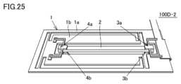
- the vibration structure 100D-2 shown in FIGS. 25 and 26 may be adopted.
- the vibration structure 100D-2 is different in the form of the connection member 3, the connection member 4, and the opening A3 frame from the vibration structure 100D (see FIG. 1). Since the other configurations are the same as those of the vibration structure 100D, the overlapping description will not be repeated.
- the vibration structure 100D-2 also has the first portion 3a and the second portion 3b of the first connecting member 3 as the connecting member, and the first portion 4a of the second connecting member 4. And a second portion 4b.
- each connecting member in the vibration structure 100D-2 has a first plate-shaped portion 3a 1 connected to the first end portion of the first electrode 2b of the piezoelectric member 2, respectively.
- Both sides of the second plate-shaped portion 3a 2 extending along the first direction D1 and connected to the frame-shaped portion 1a on both sides of the first plate-shaped portion 3a 1 and both sides of the first plate-shaped portion 3a 1 .
- the first opening A1 also serves as the third opening A3.
- FIG. 7 is a bird's-eye view of the vibration structure 100E, which is a fifth modification of the vibration structure 100.
- the vibrating structure 100E is different from the vibrating structure 100D in the form of the vibrating portion 1b and each connecting member (see FIG. 6). Since the other configurations are the same as those of the vibration structure 100D, the overlapping description is omitted.
- the vibration structure 100E also has the first portion 3a and the second portion 3b of the first connecting member 3 as the connecting member, and the first portion 4a and the second portion of the second connecting member 4.
- the part 4b of 2 is provided.
- each connecting member in the vibration structure 100E has a first plate-shaped portion 3a 1 connected to a first end portion of the first electrode 2b of the piezoelectric member 2 and a first direction.
- a second plate-shaped portion 3a 2 extending along a second direction D2 orthogonal to D1 and connected to the frame-shaped portion 1a, a first plate-shaped portion 3a 1 and a second plate-shaped portion 3a 2 It is a T-shape including a connecting portion 3a 3 for connecting the above.
- the connecting portion 3a 3 is narrower than the first plate-shaped portion 3a 1 having the same width as the piezoelectric member 2.
- the generation of tensile stress in the piezoelectric member 2 when an impact is received is generated by the first portion 3a and the second portion 3b of the first connecting member 3 which is an elastic body, and the second portion. It can be suppressed by elastic deformation of the first portion 4a and the second portion 4b of the connecting member 4 of 2. Therefore, it is possible to effectively suppress damage to the piezoelectric member 2 when it receives an impact.
- the connecting portion is also easily elastically deformed. Therefore, damage to the piezoelectric member 2 can be suppressed more effectively.
- the voltage is applied to the piezoelectric member 2 in the vibration structure 100E from the voltage application member 5 via the first portion 3a and the second portion 3b of the first connection member 3, as in the vibration structure 100. ..
- it may be a voltage supply path other than this.
- first portion 3a and the second portion 3b of the first connecting member 3 have a first step between the portion connected to the frame-shaped portion 1a and the portion connected to the piezoelectric member 2. have.
- the first step is provided in the first plate-shaped portion of the first portion 3a and the second portion 3b of the first connecting member 3.
- first portion 4a and the second portion 4b of the second connecting member 4 form a second step between the portion connected to the vibrating portion 1b and the portion connected to the piezoelectric member 2.
- a second step is provided in the first plate-shaped portion of the first portion 4a and the second portion 4b of the second connecting member 4.
- the portion where the first step and the second step are provided is not limited to this.
- the first step may be provided in the connecting portion or the second plate-shaped portion of the first portion 3a and the second portion 3b of the first connecting member 3.
- a second step may be provided in the connecting portion or the second plate-shaped portion of the first portion 4a and the second portion 4b of the second connecting member 4.
- this structure is not limited to the case where the connecting portion has a T-shape.
- the connecting portion may have the shape shown in FIG. 100D-2, and may have another shape.
- each connecting member When each connecting member is flat, it is necessary to make the piezoelectric member 2 thicker by the thickness of the voltage applying member 5. On the other hand, the thickness of the piezoelectric member 2 can be reduced by providing a step on each connecting member.
- the step of each connecting member is particularly useful when the thickness of the piezoelectric member 2 is thinner than the thickness of the vibrating portion 1b. However, it is not limited to this.
- the vibrating portion 1b sandwiches the first portion 3a and the second portion 3b of the first connecting member 3, and separates the first opening A1 and the second opening A2 from the first beam portion B1.
- the vibrating structure 100E receives an impact such that the vibrating portion 1b is displaced in the normal direction of each main surface, the first beam portion B1 comes into contact with at least one of the deformable connecting members.
- the first beam portion B1 serves as a member for suppressing deformation of the vibrating portion 1b of each connecting member in the normal direction of each main surface.
- the piezoelectric member 2 when the first portion 3a of the first connecting member 3 and the first beam portion B1 come into contact with each other, the portion of the first portion 3a of the first connecting member 3 that extends along the first direction D1. , The portion on the piezoelectric member 2 side from the portion in contact with the first beam portion B1 is displaced following the displacement of the vibrating portion 1b. Therefore, the piezoelectric member 2 also displaces following the displacement of the vibrating portion 1b. Therefore, it is possible to effectively suppress the generation of a force that causes the piezoelectric member 2 to bend in the normal direction of each main surface of the vibrating portion 1b. As a result, it is possible to effectively suppress damage due to bending of the piezoelectric member 2, especially when a piezoelectric ceramic material is used as the material of the piezoelectric member 2.
- FIG. 8 is a bird's-eye view of the vibration structure 100F, which is a sixth modification of the vibration structure 100.
- the vibration structure 100F is different from the vibration structure 100E in the form of the vibration portion 1b (see FIG. 7). Since the other configurations are the same as those of the vibration structure 100E, the overlapping description is omitted.
- the vibrating portion 1b is sandwiched between the first portion 4a and the second portion 4b of the second connecting member 4 in addition to the above-mentioned first beam portion B1. It has a second beam portion B2 that separates the second opening A2 and the fourth opening A4.
- the first beam portion B1 has the same effect as the vibrating structure 100E.
- the second beam portion B2 comes into contact with at least one of the deformable connecting members.
- the second beam portion B2 like the first beam portion B1, also serves as a member for suppressing deformation of the vibrating portion 1b of each connecting member in the normal direction.
- the piezoelectric member 2 when the first portion 4a of the second connecting member 4 and the second beam portion B2 come into contact with each other, the portion of the first portion 4a of the second connecting member 4 that extends along the first direction D1. , The portion on the piezoelectric member 2 side from the portion in contact with the second beam portion B2 is displaced following the displacement of the vibrating portion 1b. Therefore, the piezoelectric member 2 also displaces following the displacement of the vibrating portion 1b. Therefore, it is possible to effectively suppress the generation of a force that causes the piezoelectric member 2 to bend in the normal direction of each main surface of the vibrating portion 1b. As a result, it is possible to effectively suppress damage due to bending of the piezoelectric member 2, especially when a piezoelectric ceramic material is used as the material of the piezoelectric member 2.
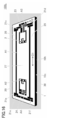
- FIG. 9A is a bird's-eye view of the vibration structure 100G, which is a seventh modification of the vibration structure 100.
- the vibration structure 100G is different from the vibration structure 100D in the form of the support portions 1c to 1f and the second plate-shaped portion 3a 2 of each connecting member (see FIG. 6). Since the other configurations are the same as those of the vibration structure 100D, the overlapping description is omitted.
- the support portions 1c to 1f have a wide V-shaped bent portion.
- the bent portion possessed by the supporting portions 1c to 1f is a supporting portion along the second direction D2.
- the bent portion of each support portion has a wide V-shape, but the present invention is not limited to this.
- the bent portion of each support portion is provided so that the V-shaped opening portion faces the vibrating portion 1b. In this case, it is possible to balance the force that causes the vibrating member 1 to be displaced along the first direction D1 generated by the expansion and contraction of each support portion.
- the second plate-shaped portion 3a 2 of each connecting member has wide V-shaped bent portions on both sides of the connecting portion with the connecting portion 3a 3. Similar to the above, when the vibrating structure 100G receives an impact such that the vibrating portion 1b is displaced along the second direction D2, the bent portion possessed by the second plate-shaped portion 3a 2 is the second It is a flat spring that enhances the elasticity of the portion along the direction D2 of.
- the bent portion of each connecting member has a wide V-shape, but the present invention is not limited to this.
- each connecting member is provided so that the V-shaped pointed portion faces the portion side extending along the first direction D1. That is, the V-shaped direction of the bent portion is opposite between the support portions 1c to 1f and the second plate-shaped portion 3a 2 of each connecting member. Also in this case, it is possible to balance the force that causes the piezoelectric member 2 to be displaced along the first direction D1 generated by the expansion and contraction of the second plate-shaped portion 3a 2 of each connecting member.
- FIG. 9B shows expansion and contraction of the bent portion of each support portion and expansion and contraction of the bent portion of the second plate-shaped portion 3a 2 of each connecting member due to the impact received by the vibration structure 100G along the second direction D2. It is a plan view which shows the deformation of the 1st part 3a of the 1st connection member 3.
- the vibration structure 100G is arranged with the support portions 1d and 1f along the second direction D2 as shown in the lower drawing of FIG. 9B. It is assumed that the vibrating portion 1b is subjected to an impact such that the vibrating portion 1b is relatively displaced in the direction from the side where the support portions 1c and 1e are arranged.
- the bent portion of the support portion 1c and 1e and the bent portion on the support portion 1c and 1e side of the second plate-shaped portion 3a 2 of each connecting member are shrunk. Then, the bent portion of the support portion 1d and 1f and the bent portion on the support portion 1d and 1f side in the second plate-shaped portion 3a 2 of each connecting member extend.
- the piezoelectric member 2 is in contact with the inner wall surface of the frame-shaped portion 1a facing the side surface of the vibrating portion 1b and the inner wall surface of the second opening A2 facing the side surface of the piezoelectric member 2.
- the vibrating portion 1b can be displaced while suppressing the deflection in the second direction D2. As a result, it is possible to effectively suppress damage due to bending of the piezoelectric member 2, especially when a piezoelectric ceramic material is used as the material of the piezoelectric member 2.
- FIG. 10 is a bird's-eye view of the vibration structure 100H, which is an eighth modification of the vibration structure 100.
- the vibration structure 100H is different from the vibration structure 100G in the form of the vibration portion 1b (see FIG. 9). Since the other configurations are the same as those of the vibration structure 100G, redundant description is omitted.
- the vibrating portion 1b is sandwiched between the first portion 3a and the second portion 3b of the first connecting member 3, and the vibrating portion 1b is sandwiched between the first portion 3a and the second portion 3b, similarly to the above-mentioned vibration structure 100E. It has a first beam portion B1 that separates the opening A1 of 1 and the second opening A2.
- the first beam portion B1 has the same effect as the vibrating structure 100E. That is, the first beam portion B1 serves as a member for suppressing deformation of the vibrating portion 1b of each connecting member in the normal direction of each main surface.
- the piezoelectric member 2 when the first portion 3a of the first connecting member 3 and the first beam portion B1 come into contact with each other, the portion of the first portion 3a of the first connecting member 3 that extends along the first direction D1. , The portion on the piezoelectric member 2 side from the portion in contact with the first beam portion B1 is displaced following the displacement of the vibrating portion 1b. Therefore, the piezoelectric member 2 also displaces following the displacement of the vibrating portion 1b. Therefore, it is possible to effectively suppress the generation of a force that causes the piezoelectric member 2 to bend in the normal direction of each main surface of the vibrating portion 1b. As a result, it is possible to effectively suppress damage due to bending of the piezoelectric member 2, especially when a piezoelectric ceramic material is used as the material of the piezoelectric member 2.
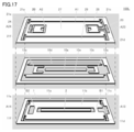
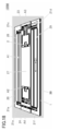
- FIG. 11A is a bird's-eye view of the vibration structure 100I, which is a ninth modification of the vibration structure 100.
- 11 (B) is a cross-sectional view taken along the line of the vibrating structure 100I cut along the plane including the X2-X2 line shown in FIG. 11 (A).
- the vibrating structure 100I further includes, in addition to the constituent members of the vibrating structure 100F, a covering member that covers a predetermined one of those constituent elements, and a cushioning member (see FIG. 8). Since the other configurations are the same as those of the vibration structure 100F, the overlapping description is omitted.
- the vibration structure 100I further includes a first covering member 7, a second covering member 8, a third covering member 9, and a first cushioning member 10.
- the first covering member 7 includes a first portion 7a and a second portion 7b.
- the second covering member 8 includes a first portion 8a and a second portion 8b.
- the third covering member 9 includes a first portion 9a and a second portion 9b.
- the first cushioning member 10 includes a first portion 10a and a second portion 10b.
- the first portion 7a of the first covering member 7 is connected to the first main surface of the vibrating portion 1b so as to straddle the second opening A2, and is connected to the first main surface side of the vibrating portion 1b. A part of the surface of the piezoelectric member 2 is covered with an interval. A first portion 10a of the first cushioning member 10 is inserted between the piezoelectric member 2 and the first portion 7a of the first covering member 7. The first portion 10a of the first cushioning member 10 is fixed to the first portion 7a of the first covering member 7. Although the piezoelectric member 2 and the first portion 10a of the first cushioning member 10 are in contact with each other, there may be a gap between them.
- the first portion 7a of the first covering member 7 is a connection portion between the piezoelectric member 2 and the first portion 3a of the first connecting member 3, and the piezoelectric member 2 and the second.
- the portion where the piezoelectric member 2 is exposed is covered between the connection portion of the connecting member 4 and the first portion 4a.
- the second portion 7b of the first covering member 7 is connected to the second main surface of the vibrating portion 1b so as to straddle the second opening A2, and is connected to the second main surface side of the vibrating portion 1b. A part of the surface of the piezoelectric member 2 is covered with an interval. A second portion 10b of the first cushioning member 10 is inserted between the piezoelectric member 2 and the second portion 7b of the first covering member 7. The second portion 10b of the first cushioning member 10 is fixed to the second portion 7b of the first covering member 7. Although the piezoelectric member 2 and the second portion 10b of the first cushioning member 10 are in contact with each other, there may be a gap between them.
- the second portion 7b of the first covering member 7 is a connection portion between the piezoelectric member 2 and the second portion 3b of the first connecting member 3, and the piezoelectric member 2 and the second portion.
- the portion where the piezoelectric member 2 is exposed is covered between the connecting portion 4b and the second portion 4b of the connecting member 4 of the above.
- the vibrating structure 100I When the vibrating structure 100I receives an impact such that the vibrating portion 1b is displaced in the normal direction of each main surface, the deformation of each main surface of the piezoelectric member 2 in the normal direction is caused by the first covering member 7. It is suppressed by the first portion 10a of the first buffer member 10 or the first portion 7a of the first covering member 7, or the second portion 7b of the first covering member 7 and the second portion 10b of the first cushioning member 10. As a result, the stress applied to the connection portion between the piezoelectric member 2 and each connecting member is reduced. As a result, peeling between the piezoelectric member 2 and each connecting member can be suppressed.
- the piezoelectric member 2 is in contact with the first portion 10a and the second portion 10b from the beginning, or at least of the first portion 10a and the second portion 10b in the process of deforming each connecting member. It suffices to make contact with one side.
- the first portion 10a of the first cushioning member 10 is formed between the piezoelectric member 2 and the first portion 7a of the first covering member 7, and the piezoelectric member 2 and the first covering member are also provided. It is preferable that the second portion 10b of the first cushioning member 10 is inserted between the second portion 7b and the piezoelectric member 2 and the piezoelectric member 2 is pressed by each cushioning member.
- a metal or the like can be used as the material of the first covering member 7.
- a metal stainless steel, tungsten alloy, titanium alloy and the like are preferable.
- a material having a Young's modulus (or secant coefficient) of 10 3 Pa or more and 10 9 Pa or less can be used as the material of the first cushioning member 10.
- rubber, polytetrafluoroethylene, polyethylene, polypropylene, polystyrene, polycarbonate, nylon and the like are preferable.
- the first portion 7a of the first covering member 7 is the first portion of the piezoelectric member 2 and the second connecting member 4 from the connection portion between the piezoelectric member 2 and the first portion 3a of the first connecting member 3. It is preferable to cover the entire surface of the piezoelectric member 2 on the first main surface side of the vibrating portion 1b, including the connection portion with the portion 4a.
- the second portion 7b of the first covering member 7 is the second portion of the piezoelectric member 2 and the second connecting member 4 from the connection portion between the piezoelectric member 2 and the second portion 3b of the first connecting member 3. It is preferable to cover the entire surface of the piezoelectric member 2 on the second main surface side of the vibrating portion 1b, including the connection portion with the portion 4b.
- each portion of the first covering member 7 covers up to the first beam portion B1. Then, in that state, the first portion 10a of the first cushioning member 10 is inserted between the piezoelectric member 2 and the first portion 7a of the first covering member 7, and the piezoelectric member 2 and the first portion 10a are inserted. It is even more preferable that the second portion 10b of the first cushioning member 10 is inserted between the covering member 7 and the second portion 7b.
- the first portion 8a of the second covering member 8 is on the support portion 1c and 1e side of the side surfaces connecting the first main surface and the second main surface of the vibrating portion 1b, and is on the frame-shaped portion 1a.
- the ridges of the first side surface and the first main surface facing the above are connected to the frame-shaped portion 1a so as to cover them at intervals.
- the second portion 8b of the second covering member 8 is formed on the frame-shaped portion 1a so as to cover the ridge line portion between the first side surface and the second main surface of the vibrating portion 1b at intervals. It is connected.
- first portion 8a and the second portion 8b of the second covering member 8 are arranged so as to face each other via the frame-shaped portion 1a, and extend along the first direction D1 together with the frame-shaped portion 1a.
- a groove is formed (see FIG. 11B). Then, the first side surface of the vibrating portion 1b and a part of each main surface connected to the first side surface are contained in the groove. It is preferable that the first portion 8a and the second portion 8b of the second covering member 8 cover the entire first side surface of the vibrating portion 1b. However, a part of the first side surface of the vibrating portion 1b may be exposed.
- the first portion 9a of the third covering member 9 is on the support portion 1d and 1f side of the side surfaces connecting the first main surface and the second main surface of the vibrating portion 1b, and is on the frame-shaped portion 1a. Is connected to the frame-shaped portion 1a so as to cover the ridges of the first side surface, the second side surface facing the back, and the first main surface at intervals. Further, the second portion 9b of the third covering member 9 is formed on the frame-shaped portion 1a so as to cover the ridge line portion between the second side surface and the second main surface of the vibrating portion 1b at intervals. It is connected.
- first portion 9a and the second portion 9b of the third covering member 9 are arranged so as to face each other via the frame-shaped portion 1a, and extend along the first direction D1 together with the frame-shaped portion 1a.
- a groove is formed (see FIG. 11B). Then, the second side surface of the vibrating portion 1b and a part of each main surface connected to the second side surface are contained in the groove.
- the first portion 9a and the second portion 9b of the third covering member 9 preferably cover the entire second side surface of the vibrating portion 1b. However, a part of the second side surface of the vibrating portion 1b may be exposed.
- the vibrating portion 1b When the vibrating structure 100I receives an impact such that the vibrating portion 1b is displaced in the normal direction of each main surface, the vibrating portion 1b has a groove in a part of each main surface of the vibrating portion 1b contained in the above groove. It can be displaced until it touches the inner wall surface of the. However, further displacement is suppressed by each covering member constituting the groove. As a result, the bending of the piezoelectric member 2 in the second direction D2 is suppressed. As a result, it is possible to effectively suppress damage due to bending of the piezoelectric member 2, especially when a piezoelectric ceramic material is used as the material of the piezoelectric member 2. In addition, peeling between the piezoelectric member 2 and each joining member can be suppressed. When the first covering member 7 is connected to the vibrating portion 1b, the above effect can be remarkably obtained.
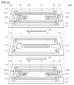
- FIG. 12 is a bird's-eye view of the vibration structure 100J, which is a tenth modification of the vibration structure 100.
- FIG. 13 is an exploded bird's-eye view of the vibration structure 100J.
- the vibrating structure 100J has basically the same components as the vibrating structure 100I. However, it is different from the vibration structure 100I in that the individual constituent members are grouped into three members (see FIG. 11). Therefore, although the reference numerals given in the drawings are different, only the correspondence relationship is described for the components corresponding to the components of the vibration structure 100I, and duplicate explanations are omitted. Similarly, duplicate description of common components is omitted.
- the vibration structure 100J includes a vibration member 1, a piezoelectric member 2, a first composite member 20, a second composite member 30, and a first cushioning member 10.
- the first cushioning member 10 includes a first portion 10a and a second portion 10b.
- the vibrating member 1 includes a first partial frame-shaped portion 11a, a first partial vibrating portion 11b, and a first partial support portion 11c to 11f, which are integrally formed.
- Each of the above-mentioned constituent members can be formed by punching one rectangular plate member so that these portions remain.
- the first partial frame-shaped portion 11a constitutes the frame-shaped portion 1a
- the first partial vibrating portion 11b constitutes the vibrating portion 1b
- the first partial support portions 11c to 11f form the support portions 1c to 1f. Consists of.
- the vibrating member 1 has a first partial opening A13 forming a third opening A3 in the frame-shaped portion 1a, and a second partial opening A14 forming a fourth opening A4 in the vibrating portion 1b. doing.
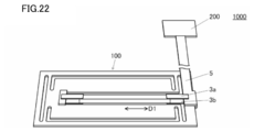
- the vibration structure 100J is connected to a circuit or device that applies a voltage to the piezoelectric member 2 such as the drive circuit 200 via the voltage application member 5.
- the voltage application member 5 and the drive circuit 200 are not shown in FIGS. 12 and 13.
- the first composite member 20 includes a second partial frame-shaped portion 21a, a second partial vibration portion 21b, a second partial support portion 21c to 21f, and a first portion 23 of the first connecting member 3.
- the first portion 24 of the second connecting member 4 the first portion 27 of the first covering member 7, the first portion 28 of the second covering member 8, and the third covering member 9. It comprises a first portion 29, which are integrally formed.
- the first portion 23 of the first connecting member 3 and the first portion 24 of the second connecting member 4 each have a first step.
- Each of the above-mentioned constituent members can be formed by punching and bending one rectangular plate member so that these portions remain.
- the first portion 10a of the first cushioning member 10 can be inserted.
- the ridgeline of the first side surface of the first partial vibration portion 11b facing the first partial frame-shaped portion 11a is formed by the first portion 28 of the second covering member 8, and the ridgeline of the second side surface is formed by the second side surface.
- the first portion 29 of the covering member 9 of 3 can be covered at intervals.
- the second partial frame-shaped portion 21a constitutes the frame-shaped portion 1a
- the second partial vibrating portion 21b constitutes the vibrating portion 1b
- the second partial support portions 21c to 21f form the support portions 1c to 1f. Consists of.
- the first composite member 20 has a third partial opening A23 forming the third opening A3 and a fourth partial opening A24 forming the fourth opening A4.
- the second composite member 30 includes a third partial frame-shaped portion 31a, a third partial vibration portion 31b, a third partial support portion 31c to 31f, and a second portion 33 of the first connecting member 3.
- the second portion 34 of the second connecting member 4 the second portion 37 of the first covering member 7, the second portion 38 of the second covering member 8, and the third covering member 9. It comprises a second portion 39, which are integrally formed.
- the second portion 33 of the first connecting member 3 and the second portion 34 of the second connecting member 4 each have a second step.
- Each of the above-mentioned constituent members can be formed by punching and bending one rectangular plate member so that these portions remain, similarly to the first composite member 20. ..
- the second portion 10b of the first cushioning member 10 can be inserted.
- the ridgeline of the first side surface of the first partial vibration portion 11b facing the first partial frame-shaped portion 11a is formed by the second portion 38 of the second covering member 8, and the ridgeline of the second side surface is formed by the second side surface.
- the second portion 39 of the covering member 9 of 3 can be covered at intervals.
- the third partial frame-shaped portion 31a constitutes the frame-shaped portion 1a
- the third partial vibrating portion 31b constitutes the vibrating portion 1b
- the third partial supporting portions 31c to 31f form the supporting portions 1c to 1f. Consists of.
- the second composite member 30 has a fifth partial opening A33 forming the third opening A3 and a sixth partial opening A34 forming the fourth opening A4 (see FIG. 13 above). ).
- each partial frame-shaped portion is integrated into a frame-shaped portion. It becomes 1a.
- each partial vibrating portion is integrated into a vibrating portion 1b, and each partial supporting portion is integrated into a supporting portion 1c to 1f.
- each constituent member is not manufactured individually, but is collectively manufactured by the vibrating member 1, the first composite member 20, and the second composite member 30. Therefore, it is possible to eliminate the complexity of individually manufacturing the constituent members. Further, even when the vibrating structure is miniaturized and the constituent members are miniaturized accordingly, it can be easily manufactured by putting them together.
- the first composite member 20 and the second composite member 30 can basically have the same structure. That is, the two are upside down from each other. In this case, it is possible to omit the distinction between the two.
- the vibration member 1 may be omitted.
- the vibrating portion 1b is a second partial vibrating portion 21b of the first composite member 20, a first portion 27 of the first covering member 7, and a third partial vibrating portion of the second composite member 30. 31b and a second portion 37 of the first covering member 7 are included.
- the vibrating member 1 is omitted, that is, even if the first partial vibrating portion 11b is omitted, the above-mentioned portions of the first composite member 20 and the second composite member 30 may generate the necessary vibration. can.
- the effect of alleviating the impact can be obtained. By omitting the vibrating member 1, the number of constituent members can be further reduced.
- FIG. 14 is a bird's-eye view of the vibration structure 100K, which is an eleventh modification of the vibration structure 100.
- FIG. 15 is an exploded bird's-eye view of the vibration structure 100K.
- the vibrating structure 100K has basically the same constituent members as the vibrating structure 100I, and the individual constituent members are grouped into three members like the vibrating structure 100J.
- the first composite member 20 and the second composite member 30 are in an upside-down relationship with each other as described above. Therefore, in FIG. 15, the illustration of the second composite member 30 is omitted.
- the first composite member 20 and the second composite member 30 of the vibration structure 100K are bent only in each connecting member to form the above-mentioned step, and the other parts are flat plates. Therefore, the vibrating structure 100K provides a spacer for creating the space described in the vibrating structure 100J between the vibrating member 1 and the first composite member 20 and between the vibrating member 1 and the second composite member 30. Further provided (see FIG. 15). Since the other configurations are the same as those of the vibration structure 100J, the overlapping description is omitted.
- spacers 10c, 10d, and 10e are sandwiched between the vibration member 1 and the first composite member 20.
- the spacer 10c has a frame shape and is arranged along the side surfaces of the first partial frame-shaped portion 11a and the second partial frame-shaped portion 21a.
- the spacers 10d and 10e are strip-shaped, and the spacers 10d and the first portion 28 of the second covering member 8 of the portion that becomes the first portion 27 of the first covering member 7 of the first composite member 20. It is arranged along the opposite first side surface. Further, the spacer 10e is arranged along the second side surface of the portion which is also the first portion 27 of the first covering member 7 and which faces the first portion 29 of the third covering member 9. .
- a spacer 10h having the same shape as the spacer 10c and a spacer 10k and 10l having the same shape as the spacers 10d and 10e are sandwiched. These are also not shown in FIG.
- the spacer 10h is arranged along the side surfaces of the first partial frame-shaped portion 11a and the third partial frame-shaped portion 31a (not shown).
- the spacer 10k is formed along the first side surface of the portion of the second composite member 30 that becomes the second portion 37 of the first covering member 7 and faces the second portion 38 of the second covering member 8. Have been placed.
- the spacer 10l is arranged along the second side surface of the portion that also becomes the second portion 37 of the first covering member 7 and faces the second portion 39 of the third covering member 9. .
- the vibration structure 100K With the vibration structure 100K, the same effect as that of the vibration structure 100I and the vibration structure 100J can be obtained. Further, although the number of constituent members is increased by the amount of the spacer, the number of bending parts can be reduced. Therefore, the manufacturing time of each composite member can be shortened. Even in the vibration structure 100K, the number of constituent members can be further reduced by omitting the vibration member 1.
- the material of the first composite member 20 and the second composite member 30 of the vibration structure 100K may be metal or resin, and a substrate material for circuit wiring may be used. In this case, the portion related to the electrical wiring can be simplified.
- FIG. 16 is a bird's-eye view of the vibration structure 100L, which is a twelfth modification of the vibration structure 100.
- FIG. 17 is an exploded bird's-eye view of the vibration structure 100L.
- the vibrating structure 100L has basically the same constituent members as the vibrating structure 100I, and individual constituent members are grouped into three members such as the vibrating structures 100J and 100K. Even in the vibration structure 100L, the first composite member 20 and the second composite member 30 are in an upside-down relationship as described above. Therefore, in FIG. 15, the illustration of the second composite member 30 is omitted.
- the width of the first plate-shaped portion of each joint member in the second direction D2 is wider than the width of the piezoelectric member 2 and is wider than the width of the piezoelectric member 2.
- the width in the second direction is narrower than the width of the first plate-shaped portion.
- the first plate-like portion of the first portion 23 of the first connecting member 3 has a first step.
- a first drawing portion is formed, and the bottom portion of the first drawing portion is connected to the piezoelectric member 2.
- a second drawing portion which is a second step, is formed in the first plate-shaped portion of the first portion 24 of the second connecting member 4, and the bottom portion of the second drawing portion is formed. Is connected to the piezoelectric member 2.
- a first drawing portion which is a first step, is formed in the first plate-shaped portion of the second portion 33 of the first connecting member 3.
- the bottom of the first drawing portion is connected to the piezoelectric member 2.
- a second drawing portion which is a second step, is formed in the first plate-shaped portion of the second portion 34 of the second connecting member 4, and the bottom portion of the second drawing portion is formed. Is connected to the piezoelectric member 2.
- the first portion 12a of the second cushioning member 12 is inserted between the two. Further, at least a part of the flat portion of the first plate-shaped portion of the first portion 24 of the second connecting member 4 in which the second drawing portion is not formed, and the first partial vibrating portion 11b.
- the first portion 13a of the third cushioning member 13 is inserted between the two.
- the first portion 12a of the second cushioning member 12 and the first portion 13a of the third cushioning member 13 are angular C-shaped and are arranged along three sides of the plate-shaped portion. However, it is not limited to this.
- spacers 10c, 10d, and 10e are sandwiched between the vibrating member 1 and the first composite member 20.
- the shape and position of each spacer are the same as those of the vibration structure 100K.
- a second portion 12b of a second cushioning member 12 is inserted between the vibrating portion 11b. Further, at least a part of a flat portion in the first plate-shaped portion of the second portion 34 of the second connecting member 4 (not shown) in which the second drawing portion is not formed, and the first partial vibration. A second portion 13b of a third cushioning member 13 (not shown) is inserted between the portion 11b.
- the second portion 12b of the second cushioning member 12 and the second portion 13b of the third cushioning member 13 are also angular C-shaped and are arranged along the three sides of the plate-shaped portion. However, it is not limited to this.
- each spacer 10h and a spacer 10k and 10l are sandwiched between the vibrating member 1 and the first composite member 20.
- the shape and position of each spacer are the same as those of the vibration structure 100K.
- the above-mentioned cushioning member is inserted between at least a part of the flat portion of the plate-shaped portion of each connecting member and the first partial vibration portion 11b.
- the number of constituent members is increased by the amount of the spacer, the number of bending parts can be reduced. Therefore, the manufacturing time of each composite member can be shortened. Even in the vibration structure 100L, the number of constituent members can be further reduced by omitting the vibration member 1.
- the structure of the first connecting member 3, the second connecting member 4, the second cushioning member 12, and the first partial vibrating portion 11b in the vibrating structure 100L is any of the vibrating structures 100A to 100I in which no composite member is used. Can also be added to the structure of.
- FIG. 18 is a bird's-eye view of the vibration structure 100M, which is a thirteenth modification of the vibration structure 100.
- FIG. 19 is an exploded bird's-eye view of the vibration structure 100M.
- the vibrating structure 100M has basically the same constituent members as the vibrating structure 100I, and individual constituent members are grouped into three members such as the vibrating structures 100J to 100K. Even in the vibration structure 100M, the first composite member 20 and the second composite member 30 are in an upside-down relationship as described above. Therefore, in FIG. 19, the illustration of the second composite member 30 is omitted.
- the vibration structure 100L is formed on a part of the first plate-shaped portion of each connecting member.
- the same drawing process as in the above is performed, whereby a portion connected to the piezoelectric member 2 is formed. That is, in the first composite member 20, the first drawing-processed portion, which is the first step, is formed in the first plate-shaped portion of the first portion 23 of the first connecting member 3, and the second A second drawing portion, which is a second step, is formed in the first plate-shaped portion of the first portion 24 of the connecting member 4.
- a first drawing portion which is a first step, is formed in the first plate-shaped portion of the second portion 33 of the first connecting member 3.
- a second drawing portion which is a second step, is formed in the first plate-shaped portion of the second portion 34 of the second connecting member 4.
- the first composite member 20 has a second partial vibrating portion 21b, a first portion 27 of the first covering member 7, and a first portion of the second covering member 8, similarly to the vibration structure 100J.
- One rectangular plate member is bent so as to form a third step between the 28 and the first portion 29 of the third covering member 9 (see FIG. 19).
- the second composite member 30 also has a third partial vibrating portion 31b, a second portion 37 of the first covering member 7, a second portion 38 of the second covering member 8, and a third covering member.
- One rectangular plate member is bent so as to form a fourth step with the second portion 39 of 9. Since the other configurations are the same as those of the vibration structure 100L, the overlapping description is omitted.
- the space created between the piezoelectric member 2 and the first portion 27 of the first covering member 7 by the third step The first portion 10a of the first cushioning member 10 can be inserted. Further, the ridgeline of the first side surface of the first partial vibration portion 11b facing the first partial frame-shaped portion 11a is formed by the first portion 28 of the second covering member 8, and the ridgeline of the second side surface is formed by the second side surface.
- the first portion 29 of the covering member 9 of 3 can be covered at intervals.
- a space created between the piezoelectric member 2 and the second portion 37 of the first covering member 7 by the fourth step is formed.
- the second portion 10b of the first cushioning member 10 can be inserted.
- the ridgeline of the first side surface of the first partial vibration portion 11b facing the first partial frame-shaped portion 11a is formed by the second portion 38 of the second covering member 8, and the ridgeline of the second side surface is formed by the second side surface.
- the second portion 39 of the covering member 9 of 3 can be covered at intervals.
- each cushioning member is inserted between at least a part of the flat portion of the plate-shaped portion of each connecting member and the first partial vibrating portion 11b.
- FIG. 20 is a bird's-eye view of the vibration structure 100N, which is a 14th modification of the vibration structure 100.
- the vibrating structure 100N has basically the same constituent members as the vibrating structure 100M, and individual constituent members are grouped into three members such as the vibrating structures 100J to 100K. Even in the vibration structure 100N, the first composite member 20 and the second composite member 30 are in an upside-down relationship as described above. The description of the configuration common to the vibration structure 100M, which is the thirteenth modification, will not be repeated.
- a concavo-convex portion as shown by a circle in FIG. 20 is provided in the central portion of any of the upper, middle, and lower diaphragms in the longitudinal direction, and is set in the first longitudinal direction D1. It is configured to act as a stopper when an impact is applied. If this stopper is not provided, both ends of the central vibrating part will collide with the outer peripheral frame, the vibrating part will bend locally in the thickness direction near the support part, and a large bending stress will be applied to the piezoelectric element fixing part. ..
- the stopper is provided in the central portion, the local deformation of the vibrator vibrating portion can be reduced, and the stress applied to the piezoelectric element can be reduced.
- FIG. 21 is a bird's-eye view of the vibration structure 100P, which is a fifteenth modification of the vibration structure 100.
- the stress relaxation member is T-shaped, but the stress relaxation member does not have to be T-shaped.
- the stress relaxation member is pulled out from the portion fixing the piezoelectric member 2 not in the first direction D1 as the longitudinal direction but in the second direction D2 as the direction orthogonal to the first direction D1. There is.
- FIG. 22 is a bird's-eye view of the vibrating device 1000.
- the vibrating device 1000 includes a vibrating structure 100 according to the present invention and a drive circuit 200 that applies a voltage to the piezoelectric member 2 included in the vibrating structure 100.
- the piezoelectric member 2 includes a prismatic piezoelectric element 2a, a first electrode 2b provided on the first main surface of the piezoelectric element 2a, and a second electrode facing the first main surface.
- the main surface of the device includes a second electrode 2c, and has a first end portion and a second end portion (see FIG. 1 (B)).
- the drive circuit 200 applies a voltage between the electrodes of the piezoelectric member 2 to expand and contract the piezoelectric member 2 in the first direction D1. ..
- the voltage is applied to the piezoelectric member 2 from the voltage applying member 5 via the first portion 3a and the second portion 3b of the first connecting member 3.
- the voltage may be applied by another method.
- the above voltage application is repeated. That is, the drive circuit 200 applies an AC voltage.
- the waveform of the applied AC voltage may be any waveform such as a rectangular wave, a triangular wave, and a trapezoidal wave. For example, by applying a sine wave, unnecessary vibration can be reduced, and by extension, the sound generated by this unnecessary vibration can be reduced.
- the vibration device 1000 according to the present invention uses the vibration structure 100 according to the present invention, it is possible to suppress a failure when receiving an impact.
- the vibration structure used may be any one according to the present invention, and is not limited to the vibration structure 100.
- FIG. 23 is a bird's-eye view of the tactile presentation device 2000.
- FIG. 24 is an exploded bird's-eye view of the tactile presentation device 2000.
- the tactile presentation device 2000 includes a vibration device 1000 according to the present invention and a pressure detection unit that detects pressure on the vibration unit 1b.
- the vibrating device 1000 includes the vibrating structure 100 according to the present invention and the drive circuit 200.
- the pressurization detection unit includes a film switch 300 and a detection circuit 400.
- a conductor line 305 is attached to the film switch 300, and the main body of the film switch 300 and the detection circuit 400 are connected by the conductor line 305.
- the drive circuit 200 applies a voltage to the piezoelectric member 2 when the pressurization detection unit detects pressurization.
- the frame-shaped portion 1a of the vibration structure 100 is placed on the substrate 600. Further, the substrate 600 is attached to the housing 800 via the cushioning member 700. The vibration structure 100 is sealed in a space formed by the substrate 600, the cushioning member 700, and the housing 800. In this structure, the vibrating portion 1b of the vibrating structure 100 may be attached to the housing 800. Further, the frame-shaped portion 1a may be attached to the housing 800 side, and the vibrating portion 1b may be attached to the substrate 600 side. Further, a spacer for height adjustment may be sandwiched between the attachment portions of the vibration structure 100, the substrate 600 and the housing 800.
- the film switch 300 detects the pressing by the user.
- the film switch 300 may be of any type as long as it can detect the pressing force by the user.
- various methods such as a membrane method, a capacitance method, and a piezoelectric film method can be used.
- the detection circuit 400 detects the press by the user.
- the drive circuit 200 applies a voltage to the piezoelectric member 2 to expand and contract the piezoelectric member 2 and vibrate the vibrating portion 1b.
- the user can feel that the film switch 300 is "pressed” by vibrating the vibrating portion 1b.
- the vibrating device used may be any one according to the present invention, and is not limited to the vibrating device 1000 in which the vibrating structure 100 is used.
- the present invention is applied to a vibration generator for, for example, for skin sensation feedback in an electronic device, or for confirming key operations by vibration.
- a vibration generator for, for example, for skin sensation feedback in an electronic device, or for confirming key operations by vibration.
- the skin sensation feedback for example, the tactile sensation image when the touch panel type display is touched may be expressed by the vibration generated by the vibration structure.
- other skin sensory feedback may be used.
- a touch panel has been shown as an example of a schematic form of a tactile presentation device using the vibration structure according to the present invention, but the present invention is not limited to this.
- a remote controller used for operating a mobile phone (so-called feature phone), a smartphone, a portable video game machine, a tablet personal computer, a notebook personal computer, a television, etc., and an automatic cash deposit / payment machine, etc.
- a touch panel type display used in a notebook computer and a touch pad used in a notebook personal computer or the like.
- the tactile presentation device 2000 when a voltage is applied to the side where the piezoelectric body contracts (the negative voltage side in the example shown in FIG. 22) as shown in FIG. 22, the peak is reached in a short time, and then the amplitude gradually increases.
- the vibrating portion 1b When an AC waveform is repeatedly applied, the vibrating portion 1b is rapidly displaced when the piezoelectric body contracts, and is gently displaced when the piezoelectric body gradually returns.
- This device that performs such an operation can also be used as a device for removing and transporting droplets, powder, and the like.
- Vibration structure 1 Vibration member 1a Frame-shaped part 1b Vibration part 1c, 1d, 1e, 1f Support part 2 Piezoelectric member 3 First connection member 3a First part 3b Second part 4 Second connection member 4a First Part 4b Second part 5 Voltage application member 6a Fixing member 7 First covering member 7a First part 7b Second part 8 Second covering member 8a First part 8b Second part 9 Third Coating member 9a 1st portion 9b 2nd portion 10 1st cushioning member 10a 1st portion 10b 2nd portion A1 1st opening A2 2nd opening A3 3rd opening A4 4th opening D1 First direction D2 Second direction
Landscapes
- Engineering & Computer Science (AREA)
- General Engineering & Computer Science (AREA)
- Theoretical Computer Science (AREA)
- Mechanical Engineering (AREA)
- Human Computer Interaction (AREA)
- Physics & Mathematics (AREA)
- General Physics & Mathematics (AREA)
- Apparatuses For Generation Of Mechanical Vibrations (AREA)
- User Interface Of Digital Computer (AREA)
Priority Applications (3)
| Application Number | Priority Date | Filing Date | Title |
|---|---|---|---|
| CN202180017545.1A CN115190824B (zh) | 2020-04-30 | 2021-04-22 | 振动构造、振动装置以及触觉提示装置 |
| JP2022517695A JP7347662B2 (ja) | 2020-04-30 | 2021-04-22 | 振動構造、振動装置および触覚提示装置 |
| US17/942,610 US20230001451A1 (en) | 2020-04-30 | 2022-09-12 | Vibration structure, vibration device, and tactile sense presentation device |
Applications Claiming Priority (2)
| Application Number | Priority Date | Filing Date | Title |
|---|---|---|---|
| JP2020-080401 | 2020-04-30 | ||
| JP2020080401 | 2020-04-30 |
Publications (1)
| Publication Number | Publication Date |
|---|---|
| WO2021220941A1 true WO2021220941A1 (ja) | 2021-11-04 |
Family
ID=78373553
Family Applications (1)
| Application Number | Title | Priority Date | Filing Date |
|---|---|---|---|
| PCT/JP2021/016357 Ceased WO2021220941A1 (ja) | 2020-04-30 | 2021-04-22 | 振動構造、振動装置および触覚提示装置 |
Country Status (4)
| Country | Link |
|---|---|
| US (1) | US20230001451A1 (https=) |
| JP (1) | JP7347662B2 (https=) |
| CN (1) | CN115190824B (https=) |
| WO (1) | WO2021220941A1 (https=) |
Cited By (1)
| Publication number | Priority date | Publication date | Assignee | Title |
|---|---|---|---|---|
| JPWO2023228703A1 (https=) * | 2022-05-24 | 2023-11-30 |
Families Citing this family (1)
| Publication number | Priority date | Publication date | Assignee | Title |
|---|---|---|---|---|
| CN117380511A (zh) * | 2023-09-22 | 2024-01-12 | 精电(河源)显示技术有限公司 | 一种振动组件及显示装置 |
Citations (2)
| Publication number | Priority date | Publication date | Assignee | Title |
|---|---|---|---|---|
| JP2007028469A (ja) * | 2005-07-21 | 2007-02-01 | Nec Tokin Corp | 音響振動発生素子、音響振動発生素子の製造方法及び音響振動発生装置 |
| WO2019013164A1 (ja) * | 2017-07-14 | 2019-01-17 | 株式会社村田製作所 | 振動構造、振動装置、および触覚提示装置 |
Family Cites Families (3)
| Publication number | Priority date | Publication date | Assignee | Title |
|---|---|---|---|---|
| JP2006144885A (ja) * | 2004-11-18 | 2006-06-08 | Toyota Motor Corp | 振動抑制装置 |
| EP2416313B1 (en) * | 2010-08-05 | 2013-11-06 | BlackBerry Limited | Electronic device including actuator for providing tactile output |
| AT15914U1 (de) * | 2017-07-26 | 2018-09-15 | Epcos Ag | Vorrichtung, die einen haptischen Feedback vermittelt und Bauelement mit der Vorrichtung |
-
2021
- 2021-04-22 CN CN202180017545.1A patent/CN115190824B/zh active Active
- 2021-04-22 JP JP2022517695A patent/JP7347662B2/ja active Active
- 2021-04-22 WO PCT/JP2021/016357 patent/WO2021220941A1/ja not_active Ceased
-
2022
- 2022-09-12 US US17/942,610 patent/US20230001451A1/en active Pending
Patent Citations (2)
| Publication number | Priority date | Publication date | Assignee | Title |
|---|---|---|---|---|
| JP2007028469A (ja) * | 2005-07-21 | 2007-02-01 | Nec Tokin Corp | 音響振動発生素子、音響振動発生素子の製造方法及び音響振動発生装置 |
| WO2019013164A1 (ja) * | 2017-07-14 | 2019-01-17 | 株式会社村田製作所 | 振動構造、振動装置、および触覚提示装置 |
Cited By (3)
| Publication number | Priority date | Publication date | Assignee | Title |
|---|---|---|---|---|
| JPWO2023228703A1 (https=) * | 2022-05-24 | 2023-11-30 | ||
| WO2023228703A1 (ja) * | 2022-05-24 | 2023-11-30 | 株式会社村田製作所 | 振動装置及び電子機器 |
| JP7613640B2 (ja) | 2022-05-24 | 2025-01-15 | 株式会社村田製作所 | 振動装置及び電子機器 |
Also Published As
| Publication number | Publication date |
|---|---|
| JP7347662B2 (ja) | 2023-09-20 |
| US20230001451A1 (en) | 2023-01-05 |
| CN115190824B (zh) | 2024-08-30 |
| CN115190824A (zh) | 2022-10-14 |
| JPWO2021220941A1 (https=) | 2021-11-04 |
Similar Documents
| Publication | Publication Date | Title |
|---|---|---|
| US11455038B2 (en) | Vibration structure, vibration device, and tactile sense presentation device | |
| US7215329B2 (en) | Touch panel input device | |
| CN103282868B (zh) | 电子设备 | |
| US20120206248A1 (en) | Flexure assemblies and fixtures for haptic feedback | |
| JP6037039B2 (ja) | 触覚提示装置 | |
| CN100430874C (zh) | 输入输出设备以及使用输入输出设备的电子设备 | |
| US20130044049A1 (en) | Electroactive polymer transducers for tactile feedback devices | |
| JP7110570B2 (ja) | 振動ユニット | |
| US20130207793A1 (en) | Electroactive polymer transducers for tactile feedback devices | |
| US10365718B2 (en) | Vibrating device and tactile sense presenting device | |
| US11009953B2 (en) | Tactile sense presenting device | |
| JP2011175518A (ja) | タッチパネル装置 | |
| WO2020213477A1 (ja) | 振動装置 | |
| JP7347662B2 (ja) | 振動構造、振動装置および触覚提示装置 | |
| JP7013767B2 (ja) | 振動ユニット | |
| JP2015185819A (ja) | バイモルフ型圧電素子の駆動装置およびこれを備えた携帯端末、音響発生器、音響発生装置、電子機器 | |
| CN102946579B (zh) | 振动材料、虚拟触觉生成器、触控模组及振膜 | |
| WO2021079837A1 (ja) | 面方向型振動構造 | |
| JP2017068795A (ja) | 触覚提示装置 | |
| JP2016053889A (ja) | 触覚提示装置 |
Legal Events
| Date | Code | Title | Description |
|---|---|---|---|
| 121 | Ep: the epo has been informed by wipo that ep was designated in this application |
Ref document number: 21796739 Country of ref document: EP Kind code of ref document: A1 |
|
| ENP | Entry into the national phase |
Ref document number: 2022517695 Country of ref document: JP Kind code of ref document: A |
|
| NENP | Non-entry into the national phase |
Ref country code: DE |
|
| 122 | Ep: pct application non-entry in european phase |
Ref document number: 21796739 Country of ref document: EP Kind code of ref document: A1 |