WO2021220941A1 - Vibration structure, vibration device, and tactile sense presentation device - Google Patents
Vibration structure, vibration device, and tactile sense presentation device Download PDFInfo
- Publication number
- WO2021220941A1 WO2021220941A1 PCT/JP2021/016357 JP2021016357W WO2021220941A1 WO 2021220941 A1 WO2021220941 A1 WO 2021220941A1 JP 2021016357 W JP2021016357 W JP 2021016357W WO 2021220941 A1 WO2021220941 A1 WO 2021220941A1
- Authority
- WO
- WIPO (PCT)
- Prior art keywords
- vibrating
- piezoelectric
- plate
- connecting member
- shaped portion
- Prior art date
Links
- 230000015541 sensory perception of touch Effects 0.000 title 1
- 239000002131 composite material Substances 0.000 claims description 69
- 238000001514 detection method Methods 0.000 claims description 10
- 239000000919 ceramic Substances 0.000 claims description 4
- 230000004048 modification Effects 0.000 description 67
- 238000012986 modification Methods 0.000 description 67
- 240000004050 Pentaglottis sempervirens Species 0.000 description 47
- 235000004522 Pentaglottis sempervirens Nutrition 0.000 description 47
- 239000000463 material Substances 0.000 description 29
- 239000000470 constituent Substances 0.000 description 27
- 125000006850 spacer group Chemical group 0.000 description 25
- 238000005452 bending Methods 0.000 description 21
- 229910010293 ceramic material Inorganic materials 0.000 description 12
- 238000006073 displacement reaction Methods 0.000 description 11
- 230000008602 contraction Effects 0.000 description 10
- 230000000694 effects Effects 0.000 description 8
- 230000005489 elastic deformation Effects 0.000 description 7
- 229910052751 metal Inorganic materials 0.000 description 7
- 239000002184 metal Substances 0.000 description 7
- 238000000034 method Methods 0.000 description 7
- 239000000758 substrate Substances 0.000 description 7
- 238000004519 manufacturing process Methods 0.000 description 6
- -1 polyethylene terephthalate Polymers 0.000 description 6
- 229920005989 resin Polymers 0.000 description 6
- 239000011347 resin Substances 0.000 description 6
- 230000035807 sensation Effects 0.000 description 5
- KAKZBPTYRLMSJV-UHFFFAOYSA-N Butadiene Chemical compound C=CC=C KAKZBPTYRLMSJV-UHFFFAOYSA-N 0.000 description 4
- PPBRXRYQALVLMV-UHFFFAOYSA-N Styrene Chemical compound C=CC1=CC=CC=C1 PPBRXRYQALVLMV-UHFFFAOYSA-N 0.000 description 4
- 230000006870 function Effects 0.000 description 4
- 229920000515 polycarbonate Polymers 0.000 description 4
- 239000004417 polycarbonate Substances 0.000 description 4
- 238000004080 punching Methods 0.000 description 4
- 229920000139 polyethylene terephthalate Polymers 0.000 description 3
- 239000005020 polyethylene terephthalate Substances 0.000 description 3
- 239000000843 powder Substances 0.000 description 3
- 238000003825 pressing Methods 0.000 description 3
- NLHHRLWOUZZQLW-UHFFFAOYSA-N Acrylonitrile Chemical compound C=CC#N NLHHRLWOUZZQLW-UHFFFAOYSA-N 0.000 description 2
- 239000004962 Polyamide-imide Substances 0.000 description 2
- 239000004642 Polyimide Substances 0.000 description 2
- 229910001069 Ti alloy Inorganic materials 0.000 description 2
- 229910001080 W alloy Inorganic materials 0.000 description 2
- 230000008859 change Effects 0.000 description 2
- 239000004020 conductor Substances 0.000 description 2
- 229920001577 copolymer Polymers 0.000 description 2
- 229920001971 elastomer Polymers 0.000 description 2
- 238000009429 electrical wiring Methods 0.000 description 2
- 239000011521 glass Substances 0.000 description 2
- 229920000747 poly(lactic acid) Polymers 0.000 description 2
- 229920002312 polyamide-imide Polymers 0.000 description 2
- 229920001721 polyimide Polymers 0.000 description 2
- 239000004626 polylactic acid Substances 0.000 description 2
- 230000008569 process Effects 0.000 description 2
- 239000005060 rubber Substances 0.000 description 2
- 239000010935 stainless steel Substances 0.000 description 2
- 229910001220 stainless steel Inorganic materials 0.000 description 2
- 229920003002 synthetic resin Polymers 0.000 description 2
- 239000000057 synthetic resin Substances 0.000 description 2
- 229920000178 Acrylic resin Polymers 0.000 description 1
- 239000004925 Acrylic resin Substances 0.000 description 1
- RYGMFSIKBFXOCR-UHFFFAOYSA-N Copper Chemical compound [Cu] RYGMFSIKBFXOCR-UHFFFAOYSA-N 0.000 description 1
- 239000004593 Epoxy Substances 0.000 description 1
- 229920002430 Fibre-reinforced plastic Polymers 0.000 description 1
- 239000004677 Nylon Substances 0.000 description 1
- 239000002033 PVDF binder Substances 0.000 description 1
- 239000004698 Polyethylene Substances 0.000 description 1
- 239000004743 Polypropylene Substances 0.000 description 1
- 239000004793 Polystyrene Substances 0.000 description 1
- 239000000853 adhesive Substances 0.000 description 1
- 230000001070 adhesive effect Effects 0.000 description 1
- 239000011248 coating agent Substances 0.000 description 1
- 238000000576 coating method Methods 0.000 description 1
- 229910052802 copper Inorganic materials 0.000 description 1
- 239000010949 copper Substances 0.000 description 1
- 230000001747 exhibiting effect Effects 0.000 description 1
- 239000011151 fibre-reinforced plastic Substances 0.000 description 1
- 238000005304 joining Methods 0.000 description 1
- 229910052451 lead zirconate titanate Inorganic materials 0.000 description 1
- HFGPZNIAWCZYJU-UHFFFAOYSA-N lead zirconate titanate Chemical compound [O-2].[O-2].[O-2].[O-2].[O-2].[Ti+4].[Zr+4].[Pb+2] HFGPZNIAWCZYJU-UHFFFAOYSA-N 0.000 description 1
- 239000012528 membrane Substances 0.000 description 1
- 229910052758 niobium Inorganic materials 0.000 description 1
- 239000010955 niobium Substances 0.000 description 1
- GUCVJGMIXFAOAE-UHFFFAOYSA-N niobium atom Chemical compound [Nb] GUCVJGMIXFAOAE-UHFFFAOYSA-N 0.000 description 1
- 229920001778 nylon Polymers 0.000 description 1
- 230000002093 peripheral effect Effects 0.000 description 1
- 229920000573 polyethylene Polymers 0.000 description 1
- 229920001155 polypropylene Polymers 0.000 description 1
- 229920002223 polystyrene Polymers 0.000 description 1
- 239000004810 polytetrafluoroethylene Substances 0.000 description 1
- 229920001343 polytetrafluoroethylene Polymers 0.000 description 1
- 229920002981 polyvinylidene fluoride Polymers 0.000 description 1
- 230000004044 response Effects 0.000 description 1
- 230000001953 sensory effect Effects 0.000 description 1
Images


Classifications
-
- B—PERFORMING OPERATIONS; TRANSPORTING
- B06—GENERATING OR TRANSMITTING MECHANICAL VIBRATIONS IN GENERAL
- B06B—METHODS OR APPARATUS FOR GENERATING OR TRANSMITTING MECHANICAL VIBRATIONS OF INFRASONIC, SONIC, OR ULTRASONIC FREQUENCY, e.g. FOR PERFORMING MECHANICAL WORK IN GENERAL
- B06B1/00—Methods or apparatus for generating mechanical vibrations of infrasonic, sonic, or ultrasonic frequency
- B06B1/02—Methods or apparatus for generating mechanical vibrations of infrasonic, sonic, or ultrasonic frequency making use of electrical energy
- B06B1/06—Methods or apparatus for generating mechanical vibrations of infrasonic, sonic, or ultrasonic frequency making use of electrical energy operating with piezoelectric effect or with electrostriction
- B06B1/0644—Methods or apparatus for generating mechanical vibrations of infrasonic, sonic, or ultrasonic frequency making use of electrical energy operating with piezoelectric effect or with electrostriction using a single piezoelectric element
-
- B—PERFORMING OPERATIONS; TRANSPORTING
- B06—GENERATING OR TRANSMITTING MECHANICAL VIBRATIONS IN GENERAL
- B06B—METHODS OR APPARATUS FOR GENERATING OR TRANSMITTING MECHANICAL VIBRATIONS OF INFRASONIC, SONIC, OR ULTRASONIC FREQUENCY, e.g. FOR PERFORMING MECHANICAL WORK IN GENERAL
- B06B1/00—Methods or apparatus for generating mechanical vibrations of infrasonic, sonic, or ultrasonic frequency
- B06B1/02—Methods or apparatus for generating mechanical vibrations of infrasonic, sonic, or ultrasonic frequency making use of electrical energy
- B06B1/06—Methods or apparatus for generating mechanical vibrations of infrasonic, sonic, or ultrasonic frequency making use of electrical energy operating with piezoelectric effect or with electrostriction
-
- B—PERFORMING OPERATIONS; TRANSPORTING
- B06—GENERATING OR TRANSMITTING MECHANICAL VIBRATIONS IN GENERAL
- B06B—METHODS OR APPARATUS FOR GENERATING OR TRANSMITTING MECHANICAL VIBRATIONS OF INFRASONIC, SONIC, OR ULTRASONIC FREQUENCY, e.g. FOR PERFORMING MECHANICAL WORK IN GENERAL
- B06B1/00—Methods or apparatus for generating mechanical vibrations of infrasonic, sonic, or ultrasonic frequency
- B06B1/02—Methods or apparatus for generating mechanical vibrations of infrasonic, sonic, or ultrasonic frequency making use of electrical energy
- B06B1/0207—Driving circuits
-
- B—PERFORMING OPERATIONS; TRANSPORTING
- B06—GENERATING OR TRANSMITTING MECHANICAL VIBRATIONS IN GENERAL
- B06B—METHODS OR APPARATUS FOR GENERATING OR TRANSMITTING MECHANICAL VIBRATIONS OF INFRASONIC, SONIC, OR ULTRASONIC FREQUENCY, e.g. FOR PERFORMING MECHANICAL WORK IN GENERAL
- B06B1/00—Methods or apparatus for generating mechanical vibrations of infrasonic, sonic, or ultrasonic frequency
- B06B1/02—Methods or apparatus for generating mechanical vibrations of infrasonic, sonic, or ultrasonic frequency making use of electrical energy
- B06B1/06—Methods or apparatus for generating mechanical vibrations of infrasonic, sonic, or ultrasonic frequency making use of electrical energy operating with piezoelectric effect or with electrostriction
- B06B1/0644—Methods or apparatus for generating mechanical vibrations of infrasonic, sonic, or ultrasonic frequency making use of electrical energy operating with piezoelectric effect or with electrostriction using a single piezoelectric element
- B06B1/0655—Methods or apparatus for generating mechanical vibrations of infrasonic, sonic, or ultrasonic frequency making use of electrical energy operating with piezoelectric effect or with electrostriction using a single piezoelectric element of cylindrical shape
-
- G—PHYSICS
- G06—COMPUTING; CALCULATING OR COUNTING
- G06F—ELECTRIC DIGITAL DATA PROCESSING
- G06F3/00—Input arrangements for transferring data to be processed into a form capable of being handled by the computer; Output arrangements for transferring data from processing unit to output unit, e.g. interface arrangements
- G06F3/01—Input arrangements or combined input and output arrangements for interaction between user and computer
- G06F3/016—Input arrangements with force or tactile feedback as computer generated output to the user
-
- G—PHYSICS
- G06—COMPUTING; CALCULATING OR COUNTING
- G06F—ELECTRIC DIGITAL DATA PROCESSING
- G06F3/00—Input arrangements for transferring data to be processed into a form capable of being handled by the computer; Output arrangements for transferring data from processing unit to output unit, e.g. interface arrangements
- G06F3/01—Input arrangements or combined input and output arrangements for interaction between user and computer
- G06F3/03—Arrangements for converting the position or the displacement of a member into a coded form
- G06F3/041—Digitisers, e.g. for touch screens or touch pads, characterised by the transducing means
-
- B—PERFORMING OPERATIONS; TRANSPORTING
- B06—GENERATING OR TRANSMITTING MECHANICAL VIBRATIONS IN GENERAL
- B06B—METHODS OR APPARATUS FOR GENERATING OR TRANSMITTING MECHANICAL VIBRATIONS OF INFRASONIC, SONIC, OR ULTRASONIC FREQUENCY, e.g. FOR PERFORMING MECHANICAL WORK IN GENERAL
- B06B2201/00—Indexing scheme associated with B06B1/0207 for details covered by B06B1/0207 but not provided for in any of its subgroups
- B06B2201/50—Application to a particular transducer type
- B06B2201/55—Piezoelectric transducer
Definitions
- the present invention relates to a vibrating structure, a vibrating device using the vibrating structure, and a tactile presentation device using the vibrating device.
- the device of the present invention can be used as a device for removing and transporting droplets, powder, and the like.
- the touch panel which is an input device that allows the user to operate the device by pressing the display on the screen, is a tactile presentation device that makes the user feel that the touch panel is pressed by transmitting vibration when the user presses the touch panel. May be provided.
- the vibration structure for generating vibration in the tactile presentation device the vibration structure described in International Publication No. 2019/013164 (Patent Document 1) can be mentioned.
- the vibrating structure described in Patent Document 1 includes a film (hereinafter referred to as a piezoelectric member) that deforms in the plane direction when a voltage is applied, and a vibrating member including a frame-shaped portion, a vibrating portion, and a supporting portion. , With connecting members.
- the frame-shaped portion has an opening, and a part of the piezoelectric member is connected.
- the vibrating portion is arranged inside the opening, and another part of the piezoelectric member is connected to the vibrating portion, and the piezoelectric member deforms in the surface direction to vibrate in the surface direction.
- the support portion supports the vibrating portion in a frame-shaped portion.
- the connecting member connects the piezoelectric member and the frame-shaped portion, and the piezoelectric member and the vibrating portion, respectively.
- the vibration structure described in Patent Document 1 is connected so that a part of the piezoelectric member and the frame-shaped portion overlap each other. That is, when the tactile presentation device incorporating the vibration structure receives an impact, tensile stress is likely to be generated in the piezoelectric member due to the impact. Therefore, the piezoelectric member may be damaged and the tactile presentation device may not operate normally.
- piezoelectric ceramics that are easily damaged by impact are used as the piezoelectric member, or when a resin piezoelectric film is used but it is fixed with tensile stress inherent, it is fixed due to the generation of tensile stress due to impact. This challenge becomes prominent when it is fragile.
- An object of the present invention is to provide a vibration structure capable of suppressing damage to a piezoelectric member when subjected to an impact, a vibration device using the vibration device, and a tactile presentation device.
- the vibrating structure includes a vibrating member including a frame-shaped portion, a vibrating portion, and a supporting portion, a piezoelectric member, a first connecting member, and a second connecting member.
- the frame-shaped portion has a first opening.
- the vibrating portion is located inside the first opening and has a second opening.
- the support portion supports the vibrating portion in the frame-shaped portion.
- the piezoelectric member is arranged inside the second opening, has a first end portion and a second end portion, and when a voltage is applied, the first end portion and the second end portion are separated from each other. It expands and contracts in the first direction of tying.
- the first connecting member connects the first end portion of the piezoelectric member and the frame-shaped portion.
- the second connecting member connects the second end portion of the piezoelectric member and the vibrating portion. And at least the first connecting member is an elastic body.
- the present invention is also directed to a vibrating device.
- the vibrating device according to the present invention includes the vibrating structure according to the present invention and a drive circuit for applying a voltage to the piezoelectric member included in the vibrating structure.
- the present invention is also directed to a tactile presentation device.
- the tactile presentation device according to the present invention includes a vibration device according to the present invention and a pressure detection unit that detects pressure on the vibration unit included in the vibration structure.
- the vibration structure according to the present invention can suppress the generation of tensile stress in the piezoelectric member when it receives an impact by elastic deformation of the first connecting member which is an elastic body. Therefore, it is possible to suppress damage to the piezoelectric member when it receives an impact. Further, since the vibration device according to the present invention uses the vibration structure according to the present invention, it is possible to suppress a failure when receiving an impact. Further, since the tactile presentation device according to the present invention uses the vibration device according to the present invention, the user can feel the tactile sensation even after receiving an impact. When this device is used as a device for removing and transporting droplets, powders, etc., it can similarly maintain its function even after being impacted.
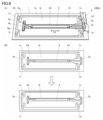
- FIG. 1A is a bird's-eye view of the vibration structure 100, which is a schematic form of the vibration structure according to the present invention.
- FIG. 1 (B) shows the connection between the piezoelectric member 2 and the first connecting member 3, and the voltage applying member 5 and the first connecting member 3, the X1-X1 line shown in FIG. 1 (A). It is a partial cross-sectional view of the vibration structure 100 cut by the plane including.
- FIG. 2A is a plan view of the vibrating structure 100 in a state before being impacted.
- the vibrating structure 100 has a first vibration structure 100 so that the vibrating portion 1b is displaced from the first portion 3a of the first connecting member 3 toward the first portion 4a of the second connecting member 4.
- the vibrating structure 100 has a first vibration structure 100 so that the vibrating portion 1b is displaced from the first portion 4a of the second connecting member 4 toward the first portion 3a of the first connecting member 3. It is a top view of the state which received the impact along the direction D1 of 1. It is a bird's-eye view of the vibration structure 100A which is the 1st modification of the vibration structure 100. It is a bird's-eye view of the vibration structure 100B which is the 2nd modification of the vibration structure 100.
- FIG. 5A is a bird's-eye view of the vibration structure 100C, which is a third modification of the vibration structure 100.
- FIG. 6A is a bird's-eye view of the vibration structure 100D, which is a fourth modification of the vibration structure 100.
- FIG. 6B the second plate-shaped portion 3a 2 of the first portion 3a of the first connecting member 3 is in the first direction due to the impact received by the vibration structure 100D along the first direction D1.
- FIG. 6E shows bending to D1.
- FIG. 9A is a bird's-eye view of the vibration structure 100G, which is a seventh modification of the vibration structure 100.
- FIG. 9B shows expansion and contraction of the bent portion of each support portion and expansion and contraction of the bent portion of the second plate-shaped portion 3a 2 of each connecting member due to the impact received by the vibration structure 100G along the second direction D2. It is a plan view which shows the deformation of the 1st part 3a of the 1st connection member 3. It is a bird's-eye view of the vibration structure 100H which is the 8th modification of the vibration structure 100.
- FIG. 9A is a bird's-eye view of the vibration structure 100G, which is a seventh modification of the vibration structure 100.
- FIG. 9B shows expansion and contraction of the bent portion of each support portion and expansion and contraction of the bent portion of the second plate-shaped portion 3a 2 of each connecting member due to the impact received by the vibration structure 100G along the second direction D2. It is a plan view which shows the deformation of the 1st part 3a
- 11A is a bird's-eye view of the vibration structure 100I, which is a ninth modification of the vibration structure 100.
- 11 (B) is a cross-sectional view taken along the line of the vibrating structure 100I cut along the plane including the X2-X2 line shown in FIG. 11 (A). It is a bird's-eye view of the vibration structure 100J which is a tenth modification of the vibration structure 100. It is an exploded bird's-eye view of the vibration structure 100J. It is a bird's-eye view of the vibration structure 100K which is the eleventh modification of the vibration structure 100. It is an exploded bird's-eye view of a vibration structure 100K.
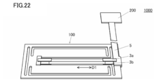
- FIG. 1A is a bird's-eye view of the vibration structure 100.
- FIG. 1 (B) shows the connection between the piezoelectric member 2 and the first connecting member 3, and the voltage applying member 5 and the first connecting member 3, the X1-X1 line shown in FIG. 1 (A). It is a partial cross-sectional view of the vibration structure 100 cut by the plane including.
- the vibration structure 100 includes a vibration member 1, a piezoelectric member 2, a first connecting member 3, and a second connecting member 4.
- the first connecting member 3 includes a first portion 3a and a second portion 3b.
- the second connecting member 4 includes a first portion 4a and a second portion 4b.
- the vibrating member 1 includes a frame-shaped portion 1a, a vibrating portion 1b, and a support portion 1c to 1f.
- the vibration structure 100 is connected to a circuit or device that applies a voltage to the piezoelectric member 2 such as a drive circuit 200 (not shown in FIG. 1) described later, for example, via a voltage application member 5.
- the vibrating member 1 has a first main surface and a second main surface facing back from the first main surface.
- the frame-shaped portion 1a of the vibrating member 1 has a first opening A1.
- the vibrating portion 1b is a plate-shaped member having a rectangular main portion and projecting portions on opposite short sides, and is arranged inside the first opening A1.
- the vibrating portion 1b is formed with a rectangular second opening A2 having a long axis along the expansion / contraction direction of the piezoelectric member 2, which will be described later in a plan view.
- the second opening A2 communicates with the first opening A1.
- the support portions 1c to 1f are strip-shaped extending in a direction orthogonal to the expansion / contraction direction of the piezoelectric member 2 described below (second direction D2 described later), and each of the support portions 1c to 1f has a frame-shaped portion 1a and a protruding portion of the vibrating portion 1b. By connecting, the vibrating portion 1b is supported by the frame-shaped portion 1a.
- the frame-shaped portion 1a, the vibration portion 1b, and the support portions 1c to 1f of the vibration member 1 are formed of the same member.
- a fiber-reinforced plastic material such as an acrylic resin, polyethylene terephthalate, polycarbonate, or glass epoxy composite material, metal, glass, or the like can be used.
- a metal stainless steel, tungsten alloy, titanium alloy and the like are preferable.
- a substrate material for circuit wiring may be used. In this case, the portion related to the electrical wiring can be simplified.
- the frame-shaped portion 1a, the vibrating portion 1b, and the support portions 1c to 1f can be formed by punching one rectangular plate member so that these portions remain.
- the frame-shaped portion 1a, the vibrating portion 1b, and the support portions 1c to 1f can be easily formed. Further, when the same member is punched, it becomes easy to match the natural vibration cycles of the plurality of support portions 1c to 1f to the same. Therefore, it is possible to reduce the vibration variation when the vibrating portion 1b is vibrated.
- the frame-shaped portion 1a, the vibrating portion 1b, and the support portions 1c to 1f do not have to be formed of the same member, and may be different members.
- the vibration state of the vibrating portion 1b can be adjusted by changing the material of each supporting portion from the materials of the frame-shaped portion 1a and the vibrating portion 1b. can.
- the vibration of the vibrating portion 1b can be increased while the voltage applied to the piezoelectric member 2 is reduced.
- the piezoelectric member 2 is formed on a prismatic piezoelectric element 2a, a first electrode 2b provided on the first main surface of the piezoelectric element 2a, and a second main surface facing the first main surface. It includes a second electrode 2c and has a first end and a second end (see FIG. 1B).
- the piezoelectric member 2 is arranged inside the second opening A2, and a voltage is applied between the above electrodes to connect the first end portion and the second end portion in the first direction D1. Expands and contracts.
- the first direction D1 which is the expansion / contraction direction of the piezoelectric member 2 and the long axis of the rectangular second opening A2 are parallel to each other.
- a piezoelectric ceramic material exhibiting a large inverse piezoelectric effect such as lead zirconate titanate and lead-free piezoelectric ceramics such as niobium-based piezoelectric ceramics can be used. In this case, the vibration of the vibrating portion 1b can be increased.
- the voltage is applied between the electrodes of the piezoelectric member 2 in the vibration structure 100 via the first portion 3a and the second portion 3b of the voltage application member 5 to the first connecting member 3, which will be described later.
- the voltage may be applied from the voltage applying member 5 via another wiring without passing through the first portion 3a and the second portion 3b of the first connecting member 3.
- the voltage may be applied not through the voltage applying member 5 but through another wiring and the first portion 3a and the second portion 3b of the first connecting member 3.
- the voltage may be applied not through the first portion 3a and the second portion 3b of the voltage applying member 5, the first connecting member 3, but through another wiring.
- the piezoelectric element 2a does not have to be a prismatic shape, and may be a columnar shape other than the prismatic shape such as a columnar shape, or may be a plate shape or a film shape.
- a resin piezoelectric film such as polyvinylidene fluoride, L-type polylactic acid, and D-type polylactic acid can be used as the material of the piezoelectric element 2a.
- the piezoelectric member 2 is a resin piezoelectric film as described above, it is preferable that the piezoelectric member 2 is connected to each connecting member described later in a state in which tensile stress is inherent, that is, in a state where tension is applied.
- the resin piezoelectric film may be connected to each connecting member so that the tensile stress is generated only when the film is contracted.
- the piezoelectric member 2 is connected to the frame-shaped portion 1a of the vibrating member 1 by the first portion 3a and the second portion 3b of the first connecting member 3, and is connected to the frame-shaped portion 1a of the vibrating member 1.
- the first portion 4a and the second portion 4b of 4 are connected to the vibrating portion 1b of the vibrating member 1.
- Each portion of the first connecting member 3 and the second connecting member 4 has a strip shape extending along the first direction D1, which is the expansion / contraction direction of the piezoelectric member 2.
- the first portion 3a of the first connecting member 3 is an elastic body, and is a first end portion of a first electrode 2b provided on a first main surface of the piezoelectric member 2 and a frame-shaped portion 1a.
- the main surface of No. 1 is connected to the main surface of No. 1 via a voltage application member 5.
- the first portion 3a of the first connecting member 3 can serve as a voltage supply path to the piezoelectric member 2.
- the second portion 3b of the first connecting member 3 and the first portion 4a and the second portion 4b of the second connecting member 4 also have the same elasticity as the first portion 3a of the first connecting member 3.
- the second portion 3b of the first connecting member 3 includes the first end portion of the second electrode 2c provided on the second main surface of the piezoelectric member 2 and the second main surface of the frame-shaped portion 1a. Is connected to the first portion 3a of the first connecting member 3 while facing the first portion 3a via the voltage applying member 5.
- the second portion 3b of the first connecting member 3 can also be a voltage supply path to the piezoelectric member 2.
- the first portion 4a of the second connecting member 4 comprises a second end portion of the first electrode 2b provided on the first main surface of the piezoelectric member 2 and a first main surface of the vibrating portion 1b. , Are connected via the fixing member 6a.
- the second portion 4b of the second connecting member 4 has a second end portion of the second electrode 2c provided on the second main surface of the piezoelectric member 2 and a second main surface of the vibrating portion 1b. , Is connected to the first portion 4a of the second connecting member 4 via a fixing member 6b (not shown) while facing the first portion 4a.
- the first portion 4a of the second connecting member 4 may connect the second end portion of the first electrode 2b and the vibrating portion 1b without passing through the fixing member 6a. Further, the second portion 4b of the second connecting member 4 may connect the second end portion of the second electrode 2c and the vibrating portion 1b without using the fixing member 6b.
- the material of the first connecting member 3 and the second connecting member 4 for example, a copolymer synthetic resin of acrylonitrile, butadiene and styrene, polyethylene terephthalate, polycarbonate, polyimide, polyamideimide, or a metal can be used.
- a copolymer synthetic resin of acrylonitrile, butadiene and styrene, polyethylene terephthalate, polycarbonate, polyimide, polyamideimide, or a metal can be used.
- one having a Young's modulus smaller than that of the vibrating member 1 and the piezoelectric member 2 can be selected from these.
- the first connecting member 3 and the second connecting member 4 function as elastic bodies due to their structures even when the Young's modulus is larger than that of the vibrating member 1 and the piezoelectric member 2. Can be done. Therefore, the magnitude relationship of Young's modulus is not an essential condition in the present invention.
- first portion 3a and the second portion 3b of the first connecting member 3 serve as a voltage supply path to the piezoelectric member 2, they further include a wiring material such as copper in addition to the above.
- a wiring material such as copper in addition to the above.
- the elastic body a stretchable material may be used, or a structural member having elasticity such as a spring may be used.
- the voltage application member 5 has a first main surface and a second main surface, and has a portion extending along a second direction D2 orthogonal to the above-mentioned first direction D1 in a plan view, and a first. It is an L-shaped flexible cable having a portion extending along the direction D1 of. Further, the voltage applying member 5 includes a cable main body 5a, a first electrode 5b provided in a portion extending along a second direction D2 on the first main surface side of the cable main body 5a, and a first main body. It has a second electrode 5c provided in a portion extending along the first direction D1 on the surface side.
- the first electrode 5b of the voltage applying member 5 is connected to the wiring included in the first portion 3a of the first connecting member 3. Further, the second electrode 5c of the voltage applying member 5 is bent through a portion extending along the first direction D1 so as to pass through the first portion 3a and the frame-shaped portion 1a of the first connecting member 3. It is connected to the wiring included in the second portion 3b of the first connecting member 3 facing each other.
- the application of the voltage between the electrodes of the piezoelectric member 2 is different from the voltage application member 5 without going through the first portion 3a and the second portion 3b of the first connecting member 3. It may be done via the wiring of.
- Reference numeral 6b is a strip shape extending along the above-mentioned second direction D2 in a plan view.
- a metal, polyethylene terephthalate, polycarbonate, polyimide, polyamide-imide, or a copolymer synthetic resin of acrylonitrile, butadiene, and styrene can be used.
- Each fixing member and each constituent member are directly adhered to each other when each fixing member itself has adhesiveness. If each fixing member itself has no adhesiveness, it may be adhered via an adhesive or the like.
- FIG. 2A is a plan view of the vibration structure 100 in a state before being impacted.
- the vibrating structure 100 has a first vibration structure 100 so that the vibrating portion 1b is displaced from the first portion 3a of the first connecting member 3 toward the first portion 4a of the second connecting member 4. It is a top view of the state which received the impact along the direction D1 of 1.
- the vibrating structure 100 has a first vibration structure 100 so that the vibrating portion 1b is displaced from the first portion 4a of the second connecting member 4 toward the first portion 3a of the first connecting member 3. It is a top view of the state which received the impact along the direction D1 of 1.
- each connecting member which is an elastic body. Therefore, since each connecting member extends from the initial state in a plan view with respect to the displacement of the vibrating portion 1b due to the impact, it is possible to suppress a change in the relative positional relationship between the vibrating member 1 and the piezoelectric member 2. That is, the generation of tensile stress in the piezoelectric member 2 due to the displacement of the vibrating portion 1b can be suppressed by elastically deforming each connecting member.
- the vibration structure 100 receives an impact from the state of FIG. 2 (A) to the state of FIG. 2 (C).
- it is possible to suppress the change in the relative positional relationship between the vibrating member 1 and the piezoelectric member 2 by contracting each connecting member in a plan view from the initial state with respect to the displacement of the vibrating portion 1b due to the impact. can. That is, as in the case shown in FIG. 2B, the generation of tensile stress in the piezoelectric member 2 due to the displacement of the vibrating portion 1b can be suppressed by elastically deforming each connecting member.
- the first end and the second end of the first main surface of the piezoelectric member 2, and the first end and the second end of the second main surface facing the first main surface and A connecting member is connected to each of the second ends. Therefore, the stress generated in each connected connecting member can be balanced between the first main surface and the second main surface. Therefore, when each connecting member expands and contracts due to the impact received by the vibrating structure 100, particularly when each connecting member contracts as shown in FIG. 2C, the piezoelectric member 2 is bent in the normal direction of the vibrating portion 1b. The generation of force can be suppressed. As a result, it is possible to suppress damage due to bending of the piezoelectric member 2, especially when a piezoelectric ceramic material is used as the material of the piezoelectric member 2.
- the vibration structure 100 according to the present invention can suppress the generation of tensile stress in the piezoelectric member 2 when it receives an impact by elastic deformation of each connecting member which is an elastic body. Therefore, it is possible to suppress damage to the piezoelectric member 2 when it receives an impact.
- FIG. 3 is a bird's-eye view of the vibration structure 100A, which is a first modification of the vibration structure 100.
- the vibrating structure 100A has a different number of connecting members from the vibrating structure 100 (see FIG. 1). Since the other configurations are the same as those of the vibration structure 100, the overlapping description is omitted.
- the vibration structure 100A includes a first portion 3a of the first connecting member 3 and a first portion 4a of the second connecting member 4 as connecting members. That is, the first end portion of the first electrode 2b of the piezoelectric member 2 is attached to the first main surface of the frame-shaped portion 1a via the voltage application member 5 by the first portion 3a of the first connecting member 3. , The second end of the first electrode 2b is connected to the first main surface of the vibrating portion 1b via the fixing member 6a by the first portion 4a of the second connecting member 4.
- the voltage applied to the piezoelectric member 2 in the vibration structure 100A is connected to the first portion 3a and the second electrode 2c of the first connecting member 3 connected from the voltage applying member 5 to the first electrode 2b. It is done via another wiring. However, it may be a voltage supply path other than this.
- the generation of tensile stress in the piezoelectric member 2 when an impact is received is generated by the first portion 3a and the second connecting member of the first connecting member 3 which is an elastic body. It can be suppressed by the elastic deformation of the first portion 4a of 4. Therefore, it is possible to suppress damage to the piezoelectric member 2 when it receives an impact.
- FIG. 4 is a bird's-eye view of the vibration structure 100B, which is a second modification of the vibration structure 100.
- the vibrating structure 100B differs from the vibrating structure 100 in the number of connecting members and the form of the fixing members (see FIG. 1). Since the other configurations are the same as those of the vibration structure 100, the overlapping description is omitted.
- the vibration structure 100B has the same structure as the vibration structure 100 (see FIG. 1 (A)).
- the first portion 4a and the second portion 4b of the second connecting member 4 are elastic bodies such as the first portion 3a and the second portion 3b of the first connecting member 3. is not it. That is, the first portion 4a of the second connecting member 4 fixes the second end portion of the first electrode 2b of the piezoelectric member 2 to the first main surface of the vibrating portion 1b via the fixing member 6a. It functions as a fixing member. Further, the second portion 4b of the second connecting member 4 vibrates the second end portion of the second electrode 2c of the piezoelectric member 2 via the fixing member 6b while facing the first portion 4a. It functions as a fixing member to be fixed to the second main surface of the portion 1b.
- the shapes of the first portion 4a and the second portion 4b of the second connecting member 4 are not limited to this.
- the fixing member 6a and the first portion 4a of the second connecting member 4 may be integrally molded. Further, the fixing member 6b and the second portion 4b of the second connecting member 4 may be integrally molded.
- the first portion 4a of the second connecting member 4 may connect the second end portion of the first electrode 2b of the piezoelectric member 2 and the vibrating portion 1b without passing through the fixing member 6a. .. Further, the second portion 4b of the second connecting member 4 may connect the second end portion of the second electrode 2c of the piezoelectric member 2 and the vibrating portion 1b without passing through the fixing member 6b. ..
- the voltage is applied to the piezoelectric member 2 in the vibration structure 100B from the voltage application member 5 via the first portion 3a and the second portion 3b of the first connection member 3, as in the vibration structure 100. ..
- it may be a voltage supply path other than this.
- the generation of tensile stress in the piezoelectric member 2 when an impact is received is generated by the first portion 3a and the second portion 3b of the first connecting member 3 which is an elastic body. It can be suppressed by the elastic deformation of. Therefore, it is possible to suppress damage to the piezoelectric member 2 when it receives an impact.
- the vibration structure 100B the first end portion and the second end portion of the first main surface of the piezoelectric member 2, and the first end of the second main surface facing the first main surface.
- a connecting member is connected to the portion and the second end portion, respectively. Therefore, the stress generated in each connected connecting member can be balanced between the first main surface and the second main surface. Therefore, when each connecting member expands and contracts due to the impact received by the vibrating structure 100B, particularly when the connecting member contracts, it is possible to suppress the generation of a force that bends the piezoelectric member 2 in the normal direction of the vibrating portion 1b. As a result, it is possible to suppress damage due to bending of the piezoelectric member 2, especially when a piezoelectric ceramic material is used as the material of the piezoelectric member 2.
- FIG. 5A is a bird's-eye view of the vibration structure 100C, which is a third modification of the vibration structure 100.
- FIG. 5B the bending portion provided in the connecting portion 3a 3 of the first portion 3a of the first connecting member 3 shrinks due to the impact received by the vibrating structure 100C along the first direction D1. It is a perspective view which shows that.
- the vibration structure 100C is different from the vibration structure 100 in the form of each connecting member (see FIG. 1). Since the other configurations are the same as those of the vibration structure 100, the overlapping description is omitted.
- the vibration structure 100C also has the first portion 3a and the second portion 3b of the first connecting member 3 as the connecting member, and the first portion of the second connecting member 4. It comprises 4a and a second portion 4b.
- each connecting member in the vibrating structure 100C has a bent portion.
- the first portion 3a of the first connecting member 3 is a first plate connected to the first end of the first electrode 2b of the piezoelectric member 2 as shown in FIG. 5 (B).
- the shape portion 3a 1 , the second plate-shaped portion 3a 2 connected to the frame-shaped portion 1a, the first plate-shaped portion 3a 1 and the second plate-shaped portion 3a 2 along the first direction D1.
- the connecting portion 3a 3 is a flat spring that enhances the elasticity of the first portion 3a of the first connecting member 3 along the first direction D1.
- the bent portion has an angular wavy shape, but the present invention is not limited to this.
- the second portion 3b of the first connecting member 3 and the first portion 4a and the second portion 4b of the second connecting member 4 have the same structure as the first portion 3a of the first connecting member 3. have. That is, the bent portion provided by the second portion 3b of the first connecting member 3 and the first portion 4a and the second portion 4b of the second connecting member 4 also follows the first direction D1.
- the voltage is applied to the piezoelectric member 2 in the vibration structure 100C from the voltage application member 5 via the first portion 3a and the second portion 3b of the first connection member 3, as in the vibration structure 100. ..
- it may be a voltage supply path other than this.
- the generation of tensile stress in the piezoelectric member 2 when an impact is received is generated by the first portion 3a and the second portion 3b of the first connecting member 3 which is an elastic body.
- the elastic deformation of the first portion 4a and the second portion 4b of the second connecting member 4 can be suppressed. Therefore, it is possible to suppress damage to the piezoelectric member 2 when it receives an impact.
- the connecting portion 3a 3 of each vibrating member is provided with a bent portion which is a flat spring as shown in FIG. 5 (B). Therefore, each vibrating member easily expands and contracts in response to an impact. Therefore, it is possible to effectively suppress damage to the piezoelectric member 2 when it receives an impact.
- the vibration structure 100C the first end portion and the second end portion of the first main surface of the piezoelectric member 2, and the first end of the second main surface facing the first main surface.
- a connecting member is connected to the portion and the second end portion, respectively. Therefore, the stress generated in each connected connecting member can be balanced between the first main surface and the second main surface. Therefore, when each connecting member expands and contracts due to the impact received by the vibrating structure 100C, particularly when the connecting member contracts, it is possible to suppress the generation of a force that bends the piezoelectric member 2 in the normal direction of the vibrating portion 1b. As a result, it is possible to suppress damage due to bending of the piezoelectric member 2, especially when a piezoelectric ceramic material is used as the material of the piezoelectric member 2.
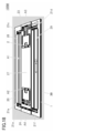
- FIG. 6A is a bird's-eye view of the vibration structure 100D, which is a fourth modification of the vibration structure 100.
- FIG. 6B the second plate-shaped portion 3a 2 of the first portion 3a of the first connecting member 3 is in the first direction due to the impact received by the vibration structure 100D along the first direction D1. It is a perspective view which shows bending to D1.
- the vibrating structure 100D differs from the vibrating structure 100 in the form of the frame-shaped portion 1a, the vibrating portion 1b, and each connecting member (see FIG. 1). Since the other configurations are the same as those of the vibration structure 100, the overlapping description is omitted.
- the vibration structure 100D also has the first portion 3a and the second portion 3b of the first connecting member 3 as the connecting member, and the first portion of the second connecting member 4. It comprises 4a and a second portion 4b.
- each connecting member in the vibration structure 100D has a first plate-shaped portion 3a 1 connected to the first end portion of the first electrode 2b of the piezoelectric member 2, respectively.
- a second plate-shaped portion 3a 2 extending along a second direction D2 orthogonal to the first direction D1 and connected to the frame-shaped portion 1a, and a first plate-shaped portion 3a 1 and a second plate-shaped portion 3a 1.
- the frame-shaped portion 1a has a third opening A3.
- the voltage applying member 5 also has an opening having the same shape as the third opening A3, which communicates with the third opening A3 when it is overlapped with the frame-shaped portion 1a.
- the third opening A3 and the opening of the voltage applying member 5 do not have to have the same shape.
- the third opening A3 communicates with the first opening A1 and the second opening A2 in the first direction D1.
- the vibrating portion 1b has a fourth opening A4.
- the fourth opening A4 communicates with the second opening A2 in the first direction D1.
- the form of the third opening A3 and the fourth opening A4 is not limited to this.
- the third opening A3 does not have to communicate with the first opening A1.
- the fourth opening A4 does not have to communicate with the second opening A2.
- the connecting portion 3a 3 is narrower than the first plate-shaped portion 3a 1 having the same width as the piezoelectric member 2.
- the width of the first plate-shaped portion 3a 1 and the connecting portion 3a 3 may be the same, and the connecting portion 3a 3 may have the above-mentioned bent portion.
- the second plate-shaped portion 3a 2 of the first portion 3a of the first connecting member 3 is a voltage applying member 5 around the third opening A3 on the first main surface of the frame-shaped portion 1a. It is connected in the form of a double-sided beam via.
- the second plate-shaped portion 3b 2 (not shown) of the second portion 3b of the first connecting member 3 has a voltage around the third opening A3 on the second main surface of the frame-shaped portion 1a. It is connected in the form of a double-sided beam via an application member 5.
- the second plate-shaped portion 4a 2 (not shown) of the first portion 4a of the second connecting member 4 is formed around the fourth opening A4 on the first main surface of the vibrating portion 1b, and the fixing member 6a is formed. It is connected in the form of a double-sided beam via 1 , 6a 2. Further, a second plate-shaped portion 4b 2 (not shown) of the second portion 4b of the second connecting member 4 is not shown around the fourth opening A4 on the second main surface of the vibrating portion 1b. It is connected in the form of a double-sided beam via fixing members 6b 1 and 6b 2.
- the voltage is applied to the piezoelectric member 2 in the vibration structure 100D from the voltage application member 5 via the first portion 3a and the second portion 3b of the first connection member 3, as in the vibration structure 100. ..
- it may be a voltage supply path other than this.
- each vibrating member has a T-shaped structure as shown in FIG. 6 (B). Therefore, the second plate-shaped portion of each vibrating member is easily bent in the first direction D1 by the impact received by the vibrating structure 100D. Therefore, it is possible to effectively suppress damage to the piezoelectric member 2 when it receives an impact.
- the connecting portion is also easily elastically deformed. Therefore, damage to the piezoelectric member 2 can be suppressed more effectively.
- the vibration structure 100D the first end portion and the second end portion of the first main surface of the piezoelectric member 2, and the first end of the second main surface facing the first main surface.
- a connecting member is connected to the portion and the second end portion, respectively. Therefore, the stress generated in each connected connecting member can be effectively balanced between the first main surface and the second main surface. Therefore, when each connecting member expands and contracts due to the impact received by the vibrating structure 100D, particularly when each connecting member contracts, the generation of a force that bends the piezoelectric member 2 in the normal direction of the vibrating portion 1b is effectively suppressed. Can be done. As a result, it is possible to suppress damage due to bending of the piezoelectric member 2, especially when a piezoelectric ceramic material is used as the material of the piezoelectric member 2.
- the connecting portion is T-shaped in FIGS. 6 (A) and 6 (B), but is not limited to this.
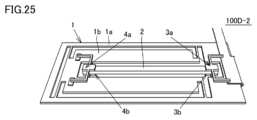
- the vibration structure 100D-2 shown in FIGS. 25 and 26 may be adopted.
- the vibration structure 100D-2 is different in the form of the connection member 3, the connection member 4, and the opening A3 frame from the vibration structure 100D (see FIG. 1). Since the other configurations are the same as those of the vibration structure 100D, the overlapping description will not be repeated.
- the vibration structure 100D-2 also has the first portion 3a and the second portion 3b of the first connecting member 3 as the connecting member, and the first portion 4a of the second connecting member 4. And a second portion 4b.
- each connecting member in the vibration structure 100D-2 has a first plate-shaped portion 3a 1 connected to the first end portion of the first electrode 2b of the piezoelectric member 2, respectively.
- Both sides of the second plate-shaped portion 3a 2 extending along the first direction D1 and connected to the frame-shaped portion 1a on both sides of the first plate-shaped portion 3a 1 and both sides of the first plate-shaped portion 3a 1 .
- the first opening A1 also serves as the third opening A3.
- FIG. 7 is a bird's-eye view of the vibration structure 100E, which is a fifth modification of the vibration structure 100.
- the vibrating structure 100E is different from the vibrating structure 100D in the form of the vibrating portion 1b and each connecting member (see FIG. 6). Since the other configurations are the same as those of the vibration structure 100D, the overlapping description is omitted.
- the vibration structure 100E also has the first portion 3a and the second portion 3b of the first connecting member 3 as the connecting member, and the first portion 4a and the second portion of the second connecting member 4.
- the part 4b of 2 is provided.
- each connecting member in the vibration structure 100E has a first plate-shaped portion 3a 1 connected to a first end portion of the first electrode 2b of the piezoelectric member 2 and a first direction.
- a second plate-shaped portion 3a 2 extending along a second direction D2 orthogonal to D1 and connected to the frame-shaped portion 1a, a first plate-shaped portion 3a 1 and a second plate-shaped portion 3a 2 It is a T-shape including a connecting portion 3a 3 for connecting the above.
- the connecting portion 3a 3 is narrower than the first plate-shaped portion 3a 1 having the same width as the piezoelectric member 2.
- the generation of tensile stress in the piezoelectric member 2 when an impact is received is generated by the first portion 3a and the second portion 3b of the first connecting member 3 which is an elastic body, and the second portion. It can be suppressed by elastic deformation of the first portion 4a and the second portion 4b of the connecting member 4 of 2. Therefore, it is possible to effectively suppress damage to the piezoelectric member 2 when it receives an impact.
- the connecting portion is also easily elastically deformed. Therefore, damage to the piezoelectric member 2 can be suppressed more effectively.
- the voltage is applied to the piezoelectric member 2 in the vibration structure 100E from the voltage application member 5 via the first portion 3a and the second portion 3b of the first connection member 3, as in the vibration structure 100. ..
- it may be a voltage supply path other than this.
- first portion 3a and the second portion 3b of the first connecting member 3 have a first step between the portion connected to the frame-shaped portion 1a and the portion connected to the piezoelectric member 2. have.
- the first step is provided in the first plate-shaped portion of the first portion 3a and the second portion 3b of the first connecting member 3.
- first portion 4a and the second portion 4b of the second connecting member 4 form a second step between the portion connected to the vibrating portion 1b and the portion connected to the piezoelectric member 2.
- a second step is provided in the first plate-shaped portion of the first portion 4a and the second portion 4b of the second connecting member 4.
- the portion where the first step and the second step are provided is not limited to this.
- the first step may be provided in the connecting portion or the second plate-shaped portion of the first portion 3a and the second portion 3b of the first connecting member 3.
- a second step may be provided in the connecting portion or the second plate-shaped portion of the first portion 4a and the second portion 4b of the second connecting member 4.
- this structure is not limited to the case where the connecting portion has a T-shape.
- the connecting portion may have the shape shown in FIG. 100D-2, and may have another shape.
- each connecting member When each connecting member is flat, it is necessary to make the piezoelectric member 2 thicker by the thickness of the voltage applying member 5. On the other hand, the thickness of the piezoelectric member 2 can be reduced by providing a step on each connecting member.
- the step of each connecting member is particularly useful when the thickness of the piezoelectric member 2 is thinner than the thickness of the vibrating portion 1b. However, it is not limited to this.
- the vibrating portion 1b sandwiches the first portion 3a and the second portion 3b of the first connecting member 3, and separates the first opening A1 and the second opening A2 from the first beam portion B1.
- the vibrating structure 100E receives an impact such that the vibrating portion 1b is displaced in the normal direction of each main surface, the first beam portion B1 comes into contact with at least one of the deformable connecting members.
- the first beam portion B1 serves as a member for suppressing deformation of the vibrating portion 1b of each connecting member in the normal direction of each main surface.
- the piezoelectric member 2 when the first portion 3a of the first connecting member 3 and the first beam portion B1 come into contact with each other, the portion of the first portion 3a of the first connecting member 3 that extends along the first direction D1. , The portion on the piezoelectric member 2 side from the portion in contact with the first beam portion B1 is displaced following the displacement of the vibrating portion 1b. Therefore, the piezoelectric member 2 also displaces following the displacement of the vibrating portion 1b. Therefore, it is possible to effectively suppress the generation of a force that causes the piezoelectric member 2 to bend in the normal direction of each main surface of the vibrating portion 1b. As a result, it is possible to effectively suppress damage due to bending of the piezoelectric member 2, especially when a piezoelectric ceramic material is used as the material of the piezoelectric member 2.
- FIG. 8 is a bird's-eye view of the vibration structure 100F, which is a sixth modification of the vibration structure 100.
- the vibration structure 100F is different from the vibration structure 100E in the form of the vibration portion 1b (see FIG. 7). Since the other configurations are the same as those of the vibration structure 100E, the overlapping description is omitted.
- the vibrating portion 1b is sandwiched between the first portion 4a and the second portion 4b of the second connecting member 4 in addition to the above-mentioned first beam portion B1. It has a second beam portion B2 that separates the second opening A2 and the fourth opening A4.
- the first beam portion B1 has the same effect as the vibrating structure 100E.
- the second beam portion B2 comes into contact with at least one of the deformable connecting members.
- the second beam portion B2 like the first beam portion B1, also serves as a member for suppressing deformation of the vibrating portion 1b of each connecting member in the normal direction.
- the piezoelectric member 2 when the first portion 4a of the second connecting member 4 and the second beam portion B2 come into contact with each other, the portion of the first portion 4a of the second connecting member 4 that extends along the first direction D1. , The portion on the piezoelectric member 2 side from the portion in contact with the second beam portion B2 is displaced following the displacement of the vibrating portion 1b. Therefore, the piezoelectric member 2 also displaces following the displacement of the vibrating portion 1b. Therefore, it is possible to effectively suppress the generation of a force that causes the piezoelectric member 2 to bend in the normal direction of each main surface of the vibrating portion 1b. As a result, it is possible to effectively suppress damage due to bending of the piezoelectric member 2, especially when a piezoelectric ceramic material is used as the material of the piezoelectric member 2.
- FIG. 9A is a bird's-eye view of the vibration structure 100G, which is a seventh modification of the vibration structure 100.
- the vibration structure 100G is different from the vibration structure 100D in the form of the support portions 1c to 1f and the second plate-shaped portion 3a 2 of each connecting member (see FIG. 6). Since the other configurations are the same as those of the vibration structure 100D, the overlapping description is omitted.
- the support portions 1c to 1f have a wide V-shaped bent portion.
- the bent portion possessed by the supporting portions 1c to 1f is a supporting portion along the second direction D2.
- the bent portion of each support portion has a wide V-shape, but the present invention is not limited to this.
- the bent portion of each support portion is provided so that the V-shaped opening portion faces the vibrating portion 1b. In this case, it is possible to balance the force that causes the vibrating member 1 to be displaced along the first direction D1 generated by the expansion and contraction of each support portion.
- the second plate-shaped portion 3a 2 of each connecting member has wide V-shaped bent portions on both sides of the connecting portion with the connecting portion 3a 3. Similar to the above, when the vibrating structure 100G receives an impact such that the vibrating portion 1b is displaced along the second direction D2, the bent portion possessed by the second plate-shaped portion 3a 2 is the second It is a flat spring that enhances the elasticity of the portion along the direction D2 of.
- the bent portion of each connecting member has a wide V-shape, but the present invention is not limited to this.
- each connecting member is provided so that the V-shaped pointed portion faces the portion side extending along the first direction D1. That is, the V-shaped direction of the bent portion is opposite between the support portions 1c to 1f and the second plate-shaped portion 3a 2 of each connecting member. Also in this case, it is possible to balance the force that causes the piezoelectric member 2 to be displaced along the first direction D1 generated by the expansion and contraction of the second plate-shaped portion 3a 2 of each connecting member.
- FIG. 9B shows expansion and contraction of the bent portion of each support portion and expansion and contraction of the bent portion of the second plate-shaped portion 3a 2 of each connecting member due to the impact received by the vibration structure 100G along the second direction D2. It is a plan view which shows the deformation of the 1st part 3a of the 1st connection member 3.
- the vibration structure 100G is arranged with the support portions 1d and 1f along the second direction D2 as shown in the lower drawing of FIG. 9B. It is assumed that the vibrating portion 1b is subjected to an impact such that the vibrating portion 1b is relatively displaced in the direction from the side where the support portions 1c and 1e are arranged.
- the bent portion of the support portion 1c and 1e and the bent portion on the support portion 1c and 1e side of the second plate-shaped portion 3a 2 of each connecting member are shrunk. Then, the bent portion of the support portion 1d and 1f and the bent portion on the support portion 1d and 1f side in the second plate-shaped portion 3a 2 of each connecting member extend.
- the piezoelectric member 2 is in contact with the inner wall surface of the frame-shaped portion 1a facing the side surface of the vibrating portion 1b and the inner wall surface of the second opening A2 facing the side surface of the piezoelectric member 2.
- the vibrating portion 1b can be displaced while suppressing the deflection in the second direction D2. As a result, it is possible to effectively suppress damage due to bending of the piezoelectric member 2, especially when a piezoelectric ceramic material is used as the material of the piezoelectric member 2.
- FIG. 10 is a bird's-eye view of the vibration structure 100H, which is an eighth modification of the vibration structure 100.
- the vibration structure 100H is different from the vibration structure 100G in the form of the vibration portion 1b (see FIG. 9). Since the other configurations are the same as those of the vibration structure 100G, redundant description is omitted.
- the vibrating portion 1b is sandwiched between the first portion 3a and the second portion 3b of the first connecting member 3, and the vibrating portion 1b is sandwiched between the first portion 3a and the second portion 3b, similarly to the above-mentioned vibration structure 100E. It has a first beam portion B1 that separates the opening A1 of 1 and the second opening A2.
- the first beam portion B1 has the same effect as the vibrating structure 100E. That is, the first beam portion B1 serves as a member for suppressing deformation of the vibrating portion 1b of each connecting member in the normal direction of each main surface.
- the piezoelectric member 2 when the first portion 3a of the first connecting member 3 and the first beam portion B1 come into contact with each other, the portion of the first portion 3a of the first connecting member 3 that extends along the first direction D1. , The portion on the piezoelectric member 2 side from the portion in contact with the first beam portion B1 is displaced following the displacement of the vibrating portion 1b. Therefore, the piezoelectric member 2 also displaces following the displacement of the vibrating portion 1b. Therefore, it is possible to effectively suppress the generation of a force that causes the piezoelectric member 2 to bend in the normal direction of each main surface of the vibrating portion 1b. As a result, it is possible to effectively suppress damage due to bending of the piezoelectric member 2, especially when a piezoelectric ceramic material is used as the material of the piezoelectric member 2.
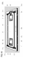
- FIG. 11A is a bird's-eye view of the vibration structure 100I, which is a ninth modification of the vibration structure 100.
- 11 (B) is a cross-sectional view taken along the line of the vibrating structure 100I cut along the plane including the X2-X2 line shown in FIG. 11 (A).
- the vibrating structure 100I further includes, in addition to the constituent members of the vibrating structure 100F, a covering member that covers a predetermined one of those constituent elements, and a cushioning member (see FIG. 8). Since the other configurations are the same as those of the vibration structure 100F, the overlapping description is omitted.
- the vibration structure 100I further includes a first covering member 7, a second covering member 8, a third covering member 9, and a first cushioning member 10.
- the first covering member 7 includes a first portion 7a and a second portion 7b.
- the second covering member 8 includes a first portion 8a and a second portion 8b.
- the third covering member 9 includes a first portion 9a and a second portion 9b.
- the first cushioning member 10 includes a first portion 10a and a second portion 10b.
- the first portion 7a of the first covering member 7 is connected to the first main surface of the vibrating portion 1b so as to straddle the second opening A2, and is connected to the first main surface side of the vibrating portion 1b. A part of the surface of the piezoelectric member 2 is covered with an interval. A first portion 10a of the first cushioning member 10 is inserted between the piezoelectric member 2 and the first portion 7a of the first covering member 7. The first portion 10a of the first cushioning member 10 is fixed to the first portion 7a of the first covering member 7. Although the piezoelectric member 2 and the first portion 10a of the first cushioning member 10 are in contact with each other, there may be a gap between them.
- the first portion 7a of the first covering member 7 is a connection portion between the piezoelectric member 2 and the first portion 3a of the first connecting member 3, and the piezoelectric member 2 and the second.
- the portion where the piezoelectric member 2 is exposed is covered between the connection portion of the connecting member 4 and the first portion 4a.
- the second portion 7b of the first covering member 7 is connected to the second main surface of the vibrating portion 1b so as to straddle the second opening A2, and is connected to the second main surface side of the vibrating portion 1b. A part of the surface of the piezoelectric member 2 is covered with an interval. A second portion 10b of the first cushioning member 10 is inserted between the piezoelectric member 2 and the second portion 7b of the first covering member 7. The second portion 10b of the first cushioning member 10 is fixed to the second portion 7b of the first covering member 7. Although the piezoelectric member 2 and the second portion 10b of the first cushioning member 10 are in contact with each other, there may be a gap between them.
- the second portion 7b of the first covering member 7 is a connection portion between the piezoelectric member 2 and the second portion 3b of the first connecting member 3, and the piezoelectric member 2 and the second portion.
- the portion where the piezoelectric member 2 is exposed is covered between the connecting portion 4b and the second portion 4b of the connecting member 4 of the above.
- the vibrating structure 100I When the vibrating structure 100I receives an impact such that the vibrating portion 1b is displaced in the normal direction of each main surface, the deformation of each main surface of the piezoelectric member 2 in the normal direction is caused by the first covering member 7. It is suppressed by the first portion 10a of the first buffer member 10 or the first portion 7a of the first covering member 7, or the second portion 7b of the first covering member 7 and the second portion 10b of the first cushioning member 10. As a result, the stress applied to the connection portion between the piezoelectric member 2 and each connecting member is reduced. As a result, peeling between the piezoelectric member 2 and each connecting member can be suppressed.
- the piezoelectric member 2 is in contact with the first portion 10a and the second portion 10b from the beginning, or at least of the first portion 10a and the second portion 10b in the process of deforming each connecting member. It suffices to make contact with one side.
- the first portion 10a of the first cushioning member 10 is formed between the piezoelectric member 2 and the first portion 7a of the first covering member 7, and the piezoelectric member 2 and the first covering member are also provided. It is preferable that the second portion 10b of the first cushioning member 10 is inserted between the second portion 7b and the piezoelectric member 2 and the piezoelectric member 2 is pressed by each cushioning member.
- a metal or the like can be used as the material of the first covering member 7.
- a metal stainless steel, tungsten alloy, titanium alloy and the like are preferable.
- a material having a Young's modulus (or secant coefficient) of 10 3 Pa or more and 10 9 Pa or less can be used as the material of the first cushioning member 10.
- rubber, polytetrafluoroethylene, polyethylene, polypropylene, polystyrene, polycarbonate, nylon and the like are preferable.
- the first portion 7a of the first covering member 7 is the first portion of the piezoelectric member 2 and the second connecting member 4 from the connection portion between the piezoelectric member 2 and the first portion 3a of the first connecting member 3. It is preferable to cover the entire surface of the piezoelectric member 2 on the first main surface side of the vibrating portion 1b, including the connection portion with the portion 4a.
- the second portion 7b of the first covering member 7 is the second portion of the piezoelectric member 2 and the second connecting member 4 from the connection portion between the piezoelectric member 2 and the second portion 3b of the first connecting member 3. It is preferable to cover the entire surface of the piezoelectric member 2 on the second main surface side of the vibrating portion 1b, including the connection portion with the portion 4b.
- each portion of the first covering member 7 covers up to the first beam portion B1. Then, in that state, the first portion 10a of the first cushioning member 10 is inserted between the piezoelectric member 2 and the first portion 7a of the first covering member 7, and the piezoelectric member 2 and the first portion 10a are inserted. It is even more preferable that the second portion 10b of the first cushioning member 10 is inserted between the covering member 7 and the second portion 7b.
- the first portion 8a of the second covering member 8 is on the support portion 1c and 1e side of the side surfaces connecting the first main surface and the second main surface of the vibrating portion 1b, and is on the frame-shaped portion 1a.
- the ridges of the first side surface and the first main surface facing the above are connected to the frame-shaped portion 1a so as to cover them at intervals.
- the second portion 8b of the second covering member 8 is formed on the frame-shaped portion 1a so as to cover the ridge line portion between the first side surface and the second main surface of the vibrating portion 1b at intervals. It is connected.
- first portion 8a and the second portion 8b of the second covering member 8 are arranged so as to face each other via the frame-shaped portion 1a, and extend along the first direction D1 together with the frame-shaped portion 1a.
- a groove is formed (see FIG. 11B). Then, the first side surface of the vibrating portion 1b and a part of each main surface connected to the first side surface are contained in the groove. It is preferable that the first portion 8a and the second portion 8b of the second covering member 8 cover the entire first side surface of the vibrating portion 1b. However, a part of the first side surface of the vibrating portion 1b may be exposed.
- the first portion 9a of the third covering member 9 is on the support portion 1d and 1f side of the side surfaces connecting the first main surface and the second main surface of the vibrating portion 1b, and is on the frame-shaped portion 1a. Is connected to the frame-shaped portion 1a so as to cover the ridges of the first side surface, the second side surface facing the back, and the first main surface at intervals. Further, the second portion 9b of the third covering member 9 is formed on the frame-shaped portion 1a so as to cover the ridge line portion between the second side surface and the second main surface of the vibrating portion 1b at intervals. It is connected.
- first portion 9a and the second portion 9b of the third covering member 9 are arranged so as to face each other via the frame-shaped portion 1a, and extend along the first direction D1 together with the frame-shaped portion 1a.
- a groove is formed (see FIG. 11B). Then, the second side surface of the vibrating portion 1b and a part of each main surface connected to the second side surface are contained in the groove.
- the first portion 9a and the second portion 9b of the third covering member 9 preferably cover the entire second side surface of the vibrating portion 1b. However, a part of the second side surface of the vibrating portion 1b may be exposed.
- the vibrating portion 1b When the vibrating structure 100I receives an impact such that the vibrating portion 1b is displaced in the normal direction of each main surface, the vibrating portion 1b has a groove in a part of each main surface of the vibrating portion 1b contained in the above groove. It can be displaced until it touches the inner wall surface of the. However, further displacement is suppressed by each covering member constituting the groove. As a result, the bending of the piezoelectric member 2 in the second direction D2 is suppressed. As a result, it is possible to effectively suppress damage due to bending of the piezoelectric member 2, especially when a piezoelectric ceramic material is used as the material of the piezoelectric member 2. In addition, peeling between the piezoelectric member 2 and each joining member can be suppressed. When the first covering member 7 is connected to the vibrating portion 1b, the above effect can be remarkably obtained.
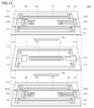
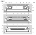
- FIG. 12 is a bird's-eye view of the vibration structure 100J, which is a tenth modification of the vibration structure 100.
- FIG. 13 is an exploded bird's-eye view of the vibration structure 100J.
- the vibrating structure 100J has basically the same components as the vibrating structure 100I. However, it is different from the vibration structure 100I in that the individual constituent members are grouped into three members (see FIG. 11). Therefore, although the reference numerals given in the drawings are different, only the correspondence relationship is described for the components corresponding to the components of the vibration structure 100I, and duplicate explanations are omitted. Similarly, duplicate description of common components is omitted.
- the vibration structure 100J includes a vibration member 1, a piezoelectric member 2, a first composite member 20, a second composite member 30, and a first cushioning member 10.
- the first cushioning member 10 includes a first portion 10a and a second portion 10b.
- the vibrating member 1 includes a first partial frame-shaped portion 11a, a first partial vibrating portion 11b, and a first partial support portion 11c to 11f, which are integrally formed.
- Each of the above-mentioned constituent members can be formed by punching one rectangular plate member so that these portions remain.
- the first partial frame-shaped portion 11a constitutes the frame-shaped portion 1a
- the first partial vibrating portion 11b constitutes the vibrating portion 1b
- the first partial support portions 11c to 11f form the support portions 1c to 1f. Consists of.
- the vibrating member 1 has a first partial opening A13 forming a third opening A3 in the frame-shaped portion 1a, and a second partial opening A14 forming a fourth opening A4 in the vibrating portion 1b. doing.
- the vibration structure 100J is connected to a circuit or device that applies a voltage to the piezoelectric member 2 such as the drive circuit 200 via the voltage application member 5.
- the voltage application member 5 and the drive circuit 200 are not shown in FIGS. 12 and 13.
- the first composite member 20 includes a second partial frame-shaped portion 21a, a second partial vibration portion 21b, a second partial support portion 21c to 21f, and a first portion 23 of the first connecting member 3.
- the first portion 24 of the second connecting member 4 the first portion 27 of the first covering member 7, the first portion 28 of the second covering member 8, and the third covering member 9. It comprises a first portion 29, which are integrally formed.
- the first portion 23 of the first connecting member 3 and the first portion 24 of the second connecting member 4 each have a first step.
- Each of the above-mentioned constituent members can be formed by punching and bending one rectangular plate member so that these portions remain.
- the first portion 10a of the first cushioning member 10 can be inserted.
- the ridgeline of the first side surface of the first partial vibration portion 11b facing the first partial frame-shaped portion 11a is formed by the first portion 28 of the second covering member 8, and the ridgeline of the second side surface is formed by the second side surface.
- the first portion 29 of the covering member 9 of 3 can be covered at intervals.
- the second partial frame-shaped portion 21a constitutes the frame-shaped portion 1a
- the second partial vibrating portion 21b constitutes the vibrating portion 1b
- the second partial support portions 21c to 21f form the support portions 1c to 1f. Consists of.
- the first composite member 20 has a third partial opening A23 forming the third opening A3 and a fourth partial opening A24 forming the fourth opening A4.
- the second composite member 30 includes a third partial frame-shaped portion 31a, a third partial vibration portion 31b, a third partial support portion 31c to 31f, and a second portion 33 of the first connecting member 3.
- the second portion 34 of the second connecting member 4 the second portion 37 of the first covering member 7, the second portion 38 of the second covering member 8, and the third covering member 9. It comprises a second portion 39, which are integrally formed.
- the second portion 33 of the first connecting member 3 and the second portion 34 of the second connecting member 4 each have a second step.
- Each of the above-mentioned constituent members can be formed by punching and bending one rectangular plate member so that these portions remain, similarly to the first composite member 20. ..
- the second portion 10b of the first cushioning member 10 can be inserted.
- the ridgeline of the first side surface of the first partial vibration portion 11b facing the first partial frame-shaped portion 11a is formed by the second portion 38 of the second covering member 8, and the ridgeline of the second side surface is formed by the second side surface.
- the second portion 39 of the covering member 9 of 3 can be covered at intervals.
- the third partial frame-shaped portion 31a constitutes the frame-shaped portion 1a
- the third partial vibrating portion 31b constitutes the vibrating portion 1b
- the third partial supporting portions 31c to 31f form the supporting portions 1c to 1f. Consists of.
- the second composite member 30 has a fifth partial opening A33 forming the third opening A3 and a sixth partial opening A34 forming the fourth opening A4 (see FIG. 13 above). ).
- each partial frame-shaped portion is integrated into a frame-shaped portion. It becomes 1a.
- each partial vibrating portion is integrated into a vibrating portion 1b, and each partial supporting portion is integrated into a supporting portion 1c to 1f.
- each constituent member is not manufactured individually, but is collectively manufactured by the vibrating member 1, the first composite member 20, and the second composite member 30. Therefore, it is possible to eliminate the complexity of individually manufacturing the constituent members. Further, even when the vibrating structure is miniaturized and the constituent members are miniaturized accordingly, it can be easily manufactured by putting them together.
- the first composite member 20 and the second composite member 30 can basically have the same structure. That is, the two are upside down from each other. In this case, it is possible to omit the distinction between the two.
- the vibration member 1 may be omitted.
- the vibrating portion 1b is a second partial vibrating portion 21b of the first composite member 20, a first portion 27 of the first covering member 7, and a third partial vibrating portion of the second composite member 30. 31b and a second portion 37 of the first covering member 7 are included.
- the vibrating member 1 is omitted, that is, even if the first partial vibrating portion 11b is omitted, the above-mentioned portions of the first composite member 20 and the second composite member 30 may generate the necessary vibration. can.
- the effect of alleviating the impact can be obtained. By omitting the vibrating member 1, the number of constituent members can be further reduced.
- FIG. 14 is a bird's-eye view of the vibration structure 100K, which is an eleventh modification of the vibration structure 100.
- FIG. 15 is an exploded bird's-eye view of the vibration structure 100K.
- the vibrating structure 100K has basically the same constituent members as the vibrating structure 100I, and the individual constituent members are grouped into three members like the vibrating structure 100J.
- the first composite member 20 and the second composite member 30 are in an upside-down relationship with each other as described above. Therefore, in FIG. 15, the illustration of the second composite member 30 is omitted.
- the first composite member 20 and the second composite member 30 of the vibration structure 100K are bent only in each connecting member to form the above-mentioned step, and the other parts are flat plates. Therefore, the vibrating structure 100K provides a spacer for creating the space described in the vibrating structure 100J between the vibrating member 1 and the first composite member 20 and between the vibrating member 1 and the second composite member 30. Further provided (see FIG. 15). Since the other configurations are the same as those of the vibration structure 100J, the overlapping description is omitted.
- spacers 10c, 10d, and 10e are sandwiched between the vibration member 1 and the first composite member 20.
- the spacer 10c has a frame shape and is arranged along the side surfaces of the first partial frame-shaped portion 11a and the second partial frame-shaped portion 21a.
- the spacers 10d and 10e are strip-shaped, and the spacers 10d and the first portion 28 of the second covering member 8 of the portion that becomes the first portion 27 of the first covering member 7 of the first composite member 20. It is arranged along the opposite first side surface. Further, the spacer 10e is arranged along the second side surface of the portion which is also the first portion 27 of the first covering member 7 and which faces the first portion 29 of the third covering member 9. .
- a spacer 10h having the same shape as the spacer 10c and a spacer 10k and 10l having the same shape as the spacers 10d and 10e are sandwiched. These are also not shown in FIG.
- the spacer 10h is arranged along the side surfaces of the first partial frame-shaped portion 11a and the third partial frame-shaped portion 31a (not shown).
- the spacer 10k is formed along the first side surface of the portion of the second composite member 30 that becomes the second portion 37 of the first covering member 7 and faces the second portion 38 of the second covering member 8. Have been placed.
- the spacer 10l is arranged along the second side surface of the portion that also becomes the second portion 37 of the first covering member 7 and faces the second portion 39 of the third covering member 9. .
- the vibration structure 100K With the vibration structure 100K, the same effect as that of the vibration structure 100I and the vibration structure 100J can be obtained. Further, although the number of constituent members is increased by the amount of the spacer, the number of bending parts can be reduced. Therefore, the manufacturing time of each composite member can be shortened. Even in the vibration structure 100K, the number of constituent members can be further reduced by omitting the vibration member 1.
- the material of the first composite member 20 and the second composite member 30 of the vibration structure 100K may be metal or resin, and a substrate material for circuit wiring may be used. In this case, the portion related to the electrical wiring can be simplified.
- FIG. 16 is a bird's-eye view of the vibration structure 100L, which is a twelfth modification of the vibration structure 100.
- FIG. 17 is an exploded bird's-eye view of the vibration structure 100L.
- the vibrating structure 100L has basically the same constituent members as the vibrating structure 100I, and individual constituent members are grouped into three members such as the vibrating structures 100J and 100K. Even in the vibration structure 100L, the first composite member 20 and the second composite member 30 are in an upside-down relationship as described above. Therefore, in FIG. 15, the illustration of the second composite member 30 is omitted.
- the width of the first plate-shaped portion of each joint member in the second direction D2 is wider than the width of the piezoelectric member 2 and is wider than the width of the piezoelectric member 2.
- the width in the second direction is narrower than the width of the first plate-shaped portion.
- the first plate-like portion of the first portion 23 of the first connecting member 3 has a first step.
- a first drawing portion is formed, and the bottom portion of the first drawing portion is connected to the piezoelectric member 2.
- a second drawing portion which is a second step, is formed in the first plate-shaped portion of the first portion 24 of the second connecting member 4, and the bottom portion of the second drawing portion is formed. Is connected to the piezoelectric member 2.
- a first drawing portion which is a first step, is formed in the first plate-shaped portion of the second portion 33 of the first connecting member 3.
- the bottom of the first drawing portion is connected to the piezoelectric member 2.
- a second drawing portion which is a second step, is formed in the first plate-shaped portion of the second portion 34 of the second connecting member 4, and the bottom portion of the second drawing portion is formed. Is connected to the piezoelectric member 2.
- the first portion 12a of the second cushioning member 12 is inserted between the two. Further, at least a part of the flat portion of the first plate-shaped portion of the first portion 24 of the second connecting member 4 in which the second drawing portion is not formed, and the first partial vibrating portion 11b.
- the first portion 13a of the third cushioning member 13 is inserted between the two.
- the first portion 12a of the second cushioning member 12 and the first portion 13a of the third cushioning member 13 are angular C-shaped and are arranged along three sides of the plate-shaped portion. However, it is not limited to this.
- spacers 10c, 10d, and 10e are sandwiched between the vibrating member 1 and the first composite member 20.
- the shape and position of each spacer are the same as those of the vibration structure 100K.
- a second portion 12b of a second cushioning member 12 is inserted between the vibrating portion 11b. Further, at least a part of a flat portion in the first plate-shaped portion of the second portion 34 of the second connecting member 4 (not shown) in which the second drawing portion is not formed, and the first partial vibration. A second portion 13b of a third cushioning member 13 (not shown) is inserted between the portion 11b.
- the second portion 12b of the second cushioning member 12 and the second portion 13b of the third cushioning member 13 are also angular C-shaped and are arranged along the three sides of the plate-shaped portion. However, it is not limited to this.
- each spacer 10h and a spacer 10k and 10l are sandwiched between the vibrating member 1 and the first composite member 20.
- the shape and position of each spacer are the same as those of the vibration structure 100K.
- the above-mentioned cushioning member is inserted between at least a part of the flat portion of the plate-shaped portion of each connecting member and the first partial vibration portion 11b.
- the number of constituent members is increased by the amount of the spacer, the number of bending parts can be reduced. Therefore, the manufacturing time of each composite member can be shortened. Even in the vibration structure 100L, the number of constituent members can be further reduced by omitting the vibration member 1.
- the structure of the first connecting member 3, the second connecting member 4, the second cushioning member 12, and the first partial vibrating portion 11b in the vibrating structure 100L is any of the vibrating structures 100A to 100I in which no composite member is used. Can also be added to the structure of.
- FIG. 18 is a bird's-eye view of the vibration structure 100M, which is a thirteenth modification of the vibration structure 100.
- FIG. 19 is an exploded bird's-eye view of the vibration structure 100M.
- the vibrating structure 100M has basically the same constituent members as the vibrating structure 100I, and individual constituent members are grouped into three members such as the vibrating structures 100J to 100K. Even in the vibration structure 100M, the first composite member 20 and the second composite member 30 are in an upside-down relationship as described above. Therefore, in FIG. 19, the illustration of the second composite member 30 is omitted.
- the vibration structure 100L is formed on a part of the first plate-shaped portion of each connecting member.
- the same drawing process as in the above is performed, whereby a portion connected to the piezoelectric member 2 is formed. That is, in the first composite member 20, the first drawing-processed portion, which is the first step, is formed in the first plate-shaped portion of the first portion 23 of the first connecting member 3, and the second A second drawing portion, which is a second step, is formed in the first plate-shaped portion of the first portion 24 of the connecting member 4.
- a first drawing portion which is a first step, is formed in the first plate-shaped portion of the second portion 33 of the first connecting member 3.
- a second drawing portion which is a second step, is formed in the first plate-shaped portion of the second portion 34 of the second connecting member 4.
- the first composite member 20 has a second partial vibrating portion 21b, a first portion 27 of the first covering member 7, and a first portion of the second covering member 8, similarly to the vibration structure 100J.
- One rectangular plate member is bent so as to form a third step between the 28 and the first portion 29 of the third covering member 9 (see FIG. 19).
- the second composite member 30 also has a third partial vibrating portion 31b, a second portion 37 of the first covering member 7, a second portion 38 of the second covering member 8, and a third covering member.
- One rectangular plate member is bent so as to form a fourth step with the second portion 39 of 9. Since the other configurations are the same as those of the vibration structure 100L, the overlapping description is omitted.
- the space created between the piezoelectric member 2 and the first portion 27 of the first covering member 7 by the third step The first portion 10a of the first cushioning member 10 can be inserted. Further, the ridgeline of the first side surface of the first partial vibration portion 11b facing the first partial frame-shaped portion 11a is formed by the first portion 28 of the second covering member 8, and the ridgeline of the second side surface is formed by the second side surface.
- the first portion 29 of the covering member 9 of 3 can be covered at intervals.
- a space created between the piezoelectric member 2 and the second portion 37 of the first covering member 7 by the fourth step is formed.
- the second portion 10b of the first cushioning member 10 can be inserted.
- the ridgeline of the first side surface of the first partial vibration portion 11b facing the first partial frame-shaped portion 11a is formed by the second portion 38 of the second covering member 8, and the ridgeline of the second side surface is formed by the second side surface.
- the second portion 39 of the covering member 9 of 3 can be covered at intervals.
- each cushioning member is inserted between at least a part of the flat portion of the plate-shaped portion of each connecting member and the first partial vibrating portion 11b.
- FIG. 20 is a bird's-eye view of the vibration structure 100N, which is a 14th modification of the vibration structure 100.
- the vibrating structure 100N has basically the same constituent members as the vibrating structure 100M, and individual constituent members are grouped into three members such as the vibrating structures 100J to 100K. Even in the vibration structure 100N, the first composite member 20 and the second composite member 30 are in an upside-down relationship as described above. The description of the configuration common to the vibration structure 100M, which is the thirteenth modification, will not be repeated.
- a concavo-convex portion as shown by a circle in FIG. 20 is provided in the central portion of any of the upper, middle, and lower diaphragms in the longitudinal direction, and is set in the first longitudinal direction D1. It is configured to act as a stopper when an impact is applied. If this stopper is not provided, both ends of the central vibrating part will collide with the outer peripheral frame, the vibrating part will bend locally in the thickness direction near the support part, and a large bending stress will be applied to the piezoelectric element fixing part. ..
- the stopper is provided in the central portion, the local deformation of the vibrator vibrating portion can be reduced, and the stress applied to the piezoelectric element can be reduced.
- FIG. 21 is a bird's-eye view of the vibration structure 100P, which is a fifteenth modification of the vibration structure 100.
- the stress relaxation member is T-shaped, but the stress relaxation member does not have to be T-shaped.
- the stress relaxation member is pulled out from the portion fixing the piezoelectric member 2 not in the first direction D1 as the longitudinal direction but in the second direction D2 as the direction orthogonal to the first direction D1. There is.
- FIG. 22 is a bird's-eye view of the vibrating device 1000.
- the vibrating device 1000 includes a vibrating structure 100 according to the present invention and a drive circuit 200 that applies a voltage to the piezoelectric member 2 included in the vibrating structure 100.
- the piezoelectric member 2 includes a prismatic piezoelectric element 2a, a first electrode 2b provided on the first main surface of the piezoelectric element 2a, and a second electrode facing the first main surface.
- the main surface of the device includes a second electrode 2c, and has a first end portion and a second end portion (see FIG. 1 (B)).
- the drive circuit 200 applies a voltage between the electrodes of the piezoelectric member 2 to expand and contract the piezoelectric member 2 in the first direction D1. ..
- the voltage is applied to the piezoelectric member 2 from the voltage applying member 5 via the first portion 3a and the second portion 3b of the first connecting member 3.
- the voltage may be applied by another method.
- the above voltage application is repeated. That is, the drive circuit 200 applies an AC voltage.
- the waveform of the applied AC voltage may be any waveform such as a rectangular wave, a triangular wave, and a trapezoidal wave. For example, by applying a sine wave, unnecessary vibration can be reduced, and by extension, the sound generated by this unnecessary vibration can be reduced.
- the vibration device 1000 according to the present invention uses the vibration structure 100 according to the present invention, it is possible to suppress a failure when receiving an impact.
- the vibration structure used may be any one according to the present invention, and is not limited to the vibration structure 100.
- FIG. 23 is a bird's-eye view of the tactile presentation device 2000.
- FIG. 24 is an exploded bird's-eye view of the tactile presentation device 2000.
- the tactile presentation device 2000 includes a vibration device 1000 according to the present invention and a pressure detection unit that detects pressure on the vibration unit 1b.
- the vibrating device 1000 includes the vibrating structure 100 according to the present invention and the drive circuit 200.
- the pressurization detection unit includes a film switch 300 and a detection circuit 400.
- a conductor line 305 is attached to the film switch 300, and the main body of the film switch 300 and the detection circuit 400 are connected by the conductor line 305.
- the drive circuit 200 applies a voltage to the piezoelectric member 2 when the pressurization detection unit detects pressurization.
- the frame-shaped portion 1a of the vibration structure 100 is placed on the substrate 600. Further, the substrate 600 is attached to the housing 800 via the cushioning member 700. The vibration structure 100 is sealed in a space formed by the substrate 600, the cushioning member 700, and the housing 800. In this structure, the vibrating portion 1b of the vibrating structure 100 may be attached to the housing 800. Further, the frame-shaped portion 1a may be attached to the housing 800 side, and the vibrating portion 1b may be attached to the substrate 600 side. Further, a spacer for height adjustment may be sandwiched between the attachment portions of the vibration structure 100, the substrate 600 and the housing 800.
- the film switch 300 detects the pressing by the user.
- the film switch 300 may be of any type as long as it can detect the pressing force by the user.
- various methods such as a membrane method, a capacitance method, and a piezoelectric film method can be used.
- the detection circuit 400 detects the press by the user.
- the drive circuit 200 applies a voltage to the piezoelectric member 2 to expand and contract the piezoelectric member 2 and vibrate the vibrating portion 1b.
- the user can feel that the film switch 300 is "pressed” by vibrating the vibrating portion 1b.
- the vibrating device used may be any one according to the present invention, and is not limited to the vibrating device 1000 in which the vibrating structure 100 is used.
- the present invention is applied to a vibration generator for, for example, for skin sensation feedback in an electronic device, or for confirming key operations by vibration.
- a vibration generator for, for example, for skin sensation feedback in an electronic device, or for confirming key operations by vibration.
- the skin sensation feedback for example, the tactile sensation image when the touch panel type display is touched may be expressed by the vibration generated by the vibration structure.
- other skin sensory feedback may be used.
- a touch panel has been shown as an example of a schematic form of a tactile presentation device using the vibration structure according to the present invention, but the present invention is not limited to this.
- a remote controller used for operating a mobile phone (so-called feature phone), a smartphone, a portable video game machine, a tablet personal computer, a notebook personal computer, a television, etc., and an automatic cash deposit / payment machine, etc.
- a touch panel type display used in a notebook computer and a touch pad used in a notebook personal computer or the like.
- the tactile presentation device 2000 when a voltage is applied to the side where the piezoelectric body contracts (the negative voltage side in the example shown in FIG. 22) as shown in FIG. 22, the peak is reached in a short time, and then the amplitude gradually increases.
- the vibrating portion 1b When an AC waveform is repeatedly applied, the vibrating portion 1b is rapidly displaced when the piezoelectric body contracts, and is gently displaced when the piezoelectric body gradually returns.
- This device that performs such an operation can also be used as a device for removing and transporting droplets, powder, and the like.
- Vibration structure 1 Vibration member 1a Frame-shaped part 1b Vibration part 1c, 1d, 1e, 1f Support part 2 Piezoelectric member 3 First connection member 3a First part 3b Second part 4 Second connection member 4a First Part 4b Second part 5 Voltage application member 6a Fixing member 7 First covering member 7a First part 7b Second part 8 Second covering member 8a First part 8b Second part 9 Third Coating member 9a 1st portion 9b 2nd portion 10 1st cushioning member 10a 1st portion 10b 2nd portion A1 1st opening A2 2nd opening A3 3rd opening A4 4th opening D1 First direction D2 Second direction
Abstract
This vibration structure (100) is provided with: a vibration member (1), comprising a frame-shaped part (1a) having a first opening (A1), a vibration part (1b) that is arranged inside the first opening (A1) and has a second opening (A2), and support sections (1c to 1f) for supporting the vibration part (1b) at the frame-shaped part (1a); a piezoelectric member (2) that is arranged inside the second opening (A2), that has a first end part and a second end part, and that expands/contracts, by application of a voltage, in a first direction (D1) linking the first end part and the second end part; a first section (3a) and a second section (3b) of a first connecting member (3) for connecting the first end part of the piezoelectric member (2) and the frame-shaped part (1a); and a first section (4a) and a second section (4b) of a second connecting member (4) for connecting the second end part of the piezoelectric member (2) and the vibration part (1b). At least the first connecting member (3) is an elastic body.
Description
この発明は、振動構造と、その振動構造を用いた振動装置と、その振動装置を用いた触覚提示装置に関する。この発明の装置は、液滴、粉体などの除去および搬送のための装置として用いることができる。
The present invention relates to a vibrating structure, a vibrating device using the vibrating structure, and a tactile presentation device using the vibrating device. The device of the present invention can be used as a device for removing and transporting droplets, powder, and the like.
利用者が画面上の表示を押すことで機器を操作する入力装置であるタッチパネルには、利用者がタッチパネルを押したときに振動を伝えることにより、タッチパネルを押したという触覚を感じさせる触覚提示装置が備えられていることがある。触覚提示装置において振動を発生させるための振動構造の一例として、国際公開第2019/013164号(特許文献1)に記載された振動構造が挙げられる。
The touch panel, which is an input device that allows the user to operate the device by pressing the display on the screen, is a tactile presentation device that makes the user feel that the touch panel is pressed by transmitting vibration when the user presses the touch panel. May be provided. As an example of the vibration structure for generating vibration in the tactile presentation device, the vibration structure described in International Publication No. 2019/013164 (Patent Document 1) can be mentioned.
特許文献1に記載された振動構造は、電圧が印加されることにより面方向に変形するフィルム(以下、圧電部材と呼称する)と、枠状部と振動部と支持部とを含む振動部材と、接続部材とを備えている。振動部材において、枠状部は、開口を有しており、圧電部材の一部が接続されている。振動部は、開口の内側に配置され、圧電部材の別の一部が接続されており、圧電部材が面方向に変形することにより、面方向に振動する。支持部は、振動部を枠状部に支持している。接続部材は、圧電部材と枠状部、および圧電部材と振動部とをそれぞれ接続している。
The vibrating structure described in Patent Document 1 includes a film (hereinafter referred to as a piezoelectric member) that deforms in the plane direction when a voltage is applied, and a vibrating member including a frame-shaped portion, a vibrating portion, and a supporting portion. , With connecting members. In the vibrating member, the frame-shaped portion has an opening, and a part of the piezoelectric member is connected. The vibrating portion is arranged inside the opening, and another part of the piezoelectric member is connected to the vibrating portion, and the piezoelectric member deforms in the surface direction to vibrate in the surface direction. The support portion supports the vibrating portion in a frame-shaped portion. The connecting member connects the piezoelectric member and the frame-shaped portion, and the piezoelectric member and the vibrating portion, respectively.
特許文献1に記載された振動構造は、圧電部材の一部と枠状部とが重なるようにして接続されている。すなわち、振動構造が組み込まれた触覚提示装置が衝撃を受けたときに、その衝撃により圧電部材内に引張応力が発生しやすい。したがって、圧電部材が破損し、触覚提示装置が正常に動作しなくなる虞がある。特に、圧電部材として、衝撃に対して破損しやすい圧電セラミックスが用いられたとき、または樹脂圧電フィルムが用いられているが引張応力が内在した状態で固定されており、衝撃による引張応力の発生により破損しやすいとき、この課題は顕著なものとなる。
The vibration structure described in Patent Document 1 is connected so that a part of the piezoelectric member and the frame-shaped portion overlap each other. That is, when the tactile presentation device incorporating the vibration structure receives an impact, tensile stress is likely to be generated in the piezoelectric member due to the impact. Therefore, the piezoelectric member may be damaged and the tactile presentation device may not operate normally. In particular, when piezoelectric ceramics that are easily damaged by impact are used as the piezoelectric member, or when a resin piezoelectric film is used but it is fixed with tensile stress inherent, it is fixed due to the generation of tensile stress due to impact. This challenge becomes prominent when it is fragile.
この発明の目的は、衝撃を受けたときの圧電部材の破損を抑制することのできる振動構造、それを用いた振動装置および触覚提示装置を提供することである。
An object of the present invention is to provide a vibration structure capable of suppressing damage to a piezoelectric member when subjected to an impact, a vibration device using the vibration device, and a tactile presentation device.
この発明は、まず振動構造に向けられる。この発明に係る振動構造は、枠状部と振動部と支持部とを含む振動部材と、圧電部材と、第1の接続部材と、第2の接続部材とを備える。枠状部は、第1の開口を有する。振動部は、第1の開口の内側に配置され、第2の開口を有する。支持部は、振動部を枠状部に支持する。圧電部材は、第2の開口の内側に配置され、第1の端部と第2の端部とを有し、電圧が印加されることにより第1の端部と第2の端部とを結ぶ第1の方向に伸縮する。第1の接続部材は、圧電部材の第1の端部と、枠状部とを接続する。第2の接続部材は、圧電部材の第2の端部と、振動部とを接続する。そして、少なくとも第1の接続部材は、弾性体である。
This invention is first directed to a vibrating structure. The vibrating structure according to the present invention includes a vibrating member including a frame-shaped portion, a vibrating portion, and a supporting portion, a piezoelectric member, a first connecting member, and a second connecting member. The frame-shaped portion has a first opening. The vibrating portion is located inside the first opening and has a second opening. The support portion supports the vibrating portion in the frame-shaped portion. The piezoelectric member is arranged inside the second opening, has a first end portion and a second end portion, and when a voltage is applied, the first end portion and the second end portion are separated from each other. It expands and contracts in the first direction of tying. The first connecting member connects the first end portion of the piezoelectric member and the frame-shaped portion. The second connecting member connects the second end portion of the piezoelectric member and the vibrating portion. And at least the first connecting member is an elastic body.
また、この発明は、振動装置にも向けられる。この発明に係る振動装置は、この発明に係る振動構造と、振動構造が備える圧電部材に電圧を印加する駆動回路とを備える。
The present invention is also directed to a vibrating device. The vibrating device according to the present invention includes the vibrating structure according to the present invention and a drive circuit for applying a voltage to the piezoelectric member included in the vibrating structure.
さらに、この発明は、触覚提示装置にも向けられる。この発明に係る触覚提示装置は、この発明に係る振動装置と、振動構造が備える振動部に対する加圧を検出する加圧検出部とを備える。
Furthermore, the present invention is also directed to a tactile presentation device. The tactile presentation device according to the present invention includes a vibration device according to the present invention and a pressure detection unit that detects pressure on the vibration unit included in the vibration structure.
この発明に係る振動構造は、衝撃を受けたときの圧電部材内の引張応力の発生を、弾性体である第1の接続部材の弾性変形により抑制することができる。そのため、衝撃を受けたときの圧電部材の破損を抑制することができる。また、この発明に係る振動装置は、この発明に係る振動構造が用いられているため、衝撃を受けたときの故障を抑制することができる。さらに、この発明に係る触覚提示装置は、この発明に係る振動装置が用いられているため、衝撃を受けた後にも利用者に触覚を感じさせることができる。この装置を、液滴、粉体などの除去および搬送のための装置として使用する場合も、同様に、衝撃を受けた後にも、その機能を維持することができる。
The vibration structure according to the present invention can suppress the generation of tensile stress in the piezoelectric member when it receives an impact by elastic deformation of the first connecting member which is an elastic body. Therefore, it is possible to suppress damage to the piezoelectric member when it receives an impact. Further, since the vibration device according to the present invention uses the vibration structure according to the present invention, it is possible to suppress a failure when receiving an impact. Further, since the tactile presentation device according to the present invention uses the vibration device according to the present invention, the user can feel the tactile sensation even after receiving an impact. When this device is used as a device for removing and transporting droplets, powders, etc., it can similarly maintain its function even after being impacted.
この開示の特徴とするところを、図面を参照しながら説明する。なお、以下に示すリニア振動モータの模式的な形態および実施形態では、同一のまたは共通する部分について図中同一の符号を付し、その説明は繰り返さないことがある。
The features of this disclosure will be explained with reference to the drawings. In the schematic form and embodiment of the linear vibration motor shown below, the same or common parts may be designated by the same reference numerals in the drawings, and the description thereof may not be repeated.
-振動構造の模式的な形態-
この発明に係る振動構造の模式的な形態である振動構造100について、図1および図2を用いて説明する。図1(A)は、振動構造100の俯瞰図である。図1(B)は、圧電部材2と第1の接続部材3、および電圧印加用部材5と第1の接続部材3との接続を示す、図1(A)に示されたX1-X1線を含む面で切断された振動構造100の部分断面図である。 -Typical form of vibration structure-
Thevibration structure 100, which is a schematic form of the vibration structure according to the present invention, will be described with reference to FIGS. 1 and 2. FIG. 1A is a bird's-eye view of the vibration structure 100. FIG. 1 (B) shows the connection between the piezoelectric member 2 and the first connecting member 3, and the voltage applying member 5 and the first connecting member 3, the X1-X1 line shown in FIG. 1 (A). It is a partial cross-sectional view of the vibration structure 100 cut by the plane including.
この発明に係る振動構造の模式的な形態である振動構造100について、図1および図2を用いて説明する。図1(A)は、振動構造100の俯瞰図である。図1(B)は、圧電部材2と第1の接続部材3、および電圧印加用部材5と第1の接続部材3との接続を示す、図1(A)に示されたX1-X1線を含む面で切断された振動構造100の部分断面図である。 -Typical form of vibration structure-
The
振動構造100は、図1に示されるように、振動部材1と、圧電部材2と、第1の接続部材3と、第2の接続部材4とを備える。第1の接続部材3は、第1の部分3aと第2の部分3bとを含んでいる。第2の接続部材4は、第1の部分4aと第2の部分4bとを含んでいる。振動部材1は、枠状部1aと振動部1bと支持部1cないし1fとを備える。なお、振動構造100は、電圧印加用部材5を介して、例えば後述する駆動回路200(図1では不図示)のような圧電部材2に電圧を印加する回路または装置と接続される。
As shown in FIG. 1, the vibration structure 100 includes a vibration member 1, a piezoelectric member 2, a first connecting member 3, and a second connecting member 4. The first connecting member 3 includes a first portion 3a and a second portion 3b. The second connecting member 4 includes a first portion 4a and a second portion 4b. The vibrating member 1 includes a frame-shaped portion 1a, a vibrating portion 1b, and a support portion 1c to 1f. The vibration structure 100 is connected to a circuit or device that applies a voltage to the piezoelectric member 2 such as a drive circuit 200 (not shown in FIG. 1) described later, for example, via a voltage application member 5.
振動部材1は、第1の主面と、第1の主面と背向する第2の主面とを有している。振動部材1の枠状部1aは、第1の開口A1を有する。振動部1bは、主要な部分が矩形状で、対向する短辺に突出部を有する板状部材であり、第1の開口A1の内側に配置されている。振動部1bには、平面視で後述する圧電部材2の伸縮方向に沿った長軸を有する矩形状の第2の開口A2が形成されている。第2の開口A2は、第1の開口A1と連通している。支持部1cないし1fは、下記の圧電部材2の伸縮方向に直交する方向(後述の第2の方向D2)に伸びる短冊状であり、それぞれが枠状部1aと振動部1bの突出部とを接続することにより、振動部1bを枠状部1aに支持している。
The vibrating member 1 has a first main surface and a second main surface facing back from the first main surface. The frame-shaped portion 1a of the vibrating member 1 has a first opening A1. The vibrating portion 1b is a plate-shaped member having a rectangular main portion and projecting portions on opposite short sides, and is arranged inside the first opening A1. The vibrating portion 1b is formed with a rectangular second opening A2 having a long axis along the expansion / contraction direction of the piezoelectric member 2, which will be described later in a plan view. The second opening A2 communicates with the first opening A1. The support portions 1c to 1f are strip-shaped extending in a direction orthogonal to the expansion / contraction direction of the piezoelectric member 2 described below (second direction D2 described later), and each of the support portions 1c to 1f has a frame-shaped portion 1a and a protruding portion of the vibrating portion 1b. By connecting, the vibrating portion 1b is supported by the frame-shaped portion 1a.
振動構造100において、振動部材1の枠状部1aと振動部1bと支持部1cないし1fとは、同一部材で形成されている。振動部材1の材質としては、例えばアクリル樹脂、ポリエチレンテレフタレート、ポリカーボネート、ガラスエポキシ複合材料などの繊維強化プラスチック材料、金属またはガラスなどを用いることができる。金属が用いられる場合は、ステンレス鋼、タングステン合金またはチタン合金などが好ましい。また、回路配線用の基板材料を用いてもよい。この場合、電気配線に係る部分を簡略化することができる。
In the vibration structure 100, the frame-shaped portion 1a, the vibration portion 1b, and the support portions 1c to 1f of the vibration member 1 are formed of the same member. As the material of the vibrating member 1, for example, a fiber-reinforced plastic material such as an acrylic resin, polyethylene terephthalate, polycarbonate, or glass epoxy composite material, metal, glass, or the like can be used. When a metal is used, stainless steel, tungsten alloy, titanium alloy and the like are preferable. Further, a substrate material for circuit wiring may be used. In this case, the portion related to the electrical wiring can be simplified.
すなわち、枠状部1aと振動部1bと支持部1cないし1fとは、1枚の矩形状の板部材が、これらの部位が残るように打ち抜き加工されることにより形成することができる。この場合、枠状部1aと振動部1bと支持部1cないし1fとを容易に形成することができる。さらに、同一部材でかつ打ち抜き加工を行なう場合、複数の支持部1cないし1fの固有振動周期を同じに合わせやすくなる。そのため、振動部1bを振動させたときの振動ばらつきを軽減させることができる。
That is, the frame-shaped portion 1a, the vibrating portion 1b, and the support portions 1c to 1f can be formed by punching one rectangular plate member so that these portions remain. In this case, the frame-shaped portion 1a, the vibrating portion 1b, and the support portions 1c to 1f can be easily formed. Further, when the same member is punched, it becomes easy to match the natural vibration cycles of the plurality of support portions 1c to 1f to the same. Therefore, it is possible to reduce the vibration variation when the vibrating portion 1b is vibrated.
ただし、この発明において、枠状部1aと振動部1bと支持部1cないし1fとは、同一部材で形成される必要はなく、それぞれ別の部材であってもよい。例えば、複数の支持部1cないし1fを別の部材とした場合、各支持部の材質を枠状部1aおよび振動部1bの材質から変更することにより、振動部1bの振動状態を調整することができる。例えば、支持部1cないし1fにゴムなどの材料を用いた場合、圧電部材2に印加する電圧を小さくしながら、振動部1bの振動を大きくすることができる。
However, in the present invention, the frame-shaped portion 1a, the vibrating portion 1b, and the support portions 1c to 1f do not have to be formed of the same member, and may be different members. For example, when a plurality of support portions 1c to 1f are used as different members, the vibration state of the vibrating portion 1b can be adjusted by changing the material of each supporting portion from the materials of the frame-shaped portion 1a and the vibrating portion 1b. can. For example, when a material such as rubber is used for the support portions 1c to 1f, the vibration of the vibrating portion 1b can be increased while the voltage applied to the piezoelectric member 2 is reduced.
圧電部材2は、角柱状の圧電体素子2aと、圧電体素子2aの第1の主面に設けられた第1の電極2bと、第1の主面と背向する第2の主面に第2の電極2cとを含み、第1の端部と第2の端部とを有している(図1(B)参照)。圧電部材2は、第2の開口A2の内側に配置され、上記のそれぞれの電極間に電圧が印加されることにより、第1の端部と第2の端部とを結ぶ第1の方向D1に伸縮する。前述したように、圧電部材2の伸縮方向である第1の方向D1と、矩形状の第2の開口A2の長軸とは平行となっている。圧電体素子2aの材質としては、例えばチタン酸ジルコン酸鉛および例えばニオブ系圧電セラミックスなどの無鉛圧電セラミックスのような大きな逆圧電効果を示す圧電セラミックス材料を用いることができる。この場合、振動部1bの振動を大きくすることができる。
The piezoelectric member 2 is formed on a prismatic piezoelectric element 2a, a first electrode 2b provided on the first main surface of the piezoelectric element 2a, and a second main surface facing the first main surface. It includes a second electrode 2c and has a first end and a second end (see FIG. 1B). The piezoelectric member 2 is arranged inside the second opening A2, and a voltage is applied between the above electrodes to connect the first end portion and the second end portion in the first direction D1. Expands and contracts. As described above, the first direction D1 which is the expansion / contraction direction of the piezoelectric member 2 and the long axis of the rectangular second opening A2 are parallel to each other. As the material of the piezoelectric element 2a, a piezoelectric ceramic material exhibiting a large inverse piezoelectric effect such as lead zirconate titanate and lead-free piezoelectric ceramics such as niobium-based piezoelectric ceramics can be used. In this case, the vibration of the vibrating portion 1b can be increased.
振動構造100における圧電部材2の電極間への電圧の印加は、後述する電圧印加用部材5から第1の接続部材3の第1の部分3aおよび第2の部分3bを介して行なわれる。ただし、第1の接続部材3の第1の部分3aおよび第2の部分3bを介さず、電圧印加用部材5から別の配線を介して電圧の印加が行なわれてもよい。また、電圧印加用部材5を介さず、別の配線ならびに第1の接続部材3の第1の部分3aおよび第2の部分3bを介して電圧の印加が行なわれてもよい。さらに、電圧印加用部材5、第1の接続部材3の第1の部分3aおよび第2の部分3bを介さず、別の配線を介して電圧の印加が行なわれてもよい。
The voltage is applied between the electrodes of the piezoelectric member 2 in the vibration structure 100 via the first portion 3a and the second portion 3b of the voltage application member 5 to the first connecting member 3, which will be described later. However, the voltage may be applied from the voltage applying member 5 via another wiring without passing through the first portion 3a and the second portion 3b of the first connecting member 3. Further, the voltage may be applied not through the voltage applying member 5 but through another wiring and the first portion 3a and the second portion 3b of the first connecting member 3. Further, the voltage may be applied not through the first portion 3a and the second portion 3b of the voltage applying member 5, the first connecting member 3, but through another wiring.
ただし、この発明において、圧電体素子2aは、角柱状である必要はなく、円柱状など角柱状以外の柱状であってもよく、板状またはフィルム状であってもよい。例えば、圧電体素子2aが板状またはフィルム状である場合、圧電体素子2aの材質として、ポリフッ化ビニリデン、L型ポリ乳酸およびD型ポリ乳酸のような樹脂圧電フィルムを用いることができる。圧電部材2が上記のような樹脂圧電フィルムである場合、引張応力が内在する状態、すなわち張力の掛かった状態で後述する各接続部材に接続されることが好ましい。ただし、樹脂圧電フィルムに引張応力が内在していることは必須ではなく、収縮したときにのみ引張応力が発生するように各接続部材に接続されていてもよい。
However, in the present invention, the piezoelectric element 2a does not have to be a prismatic shape, and may be a columnar shape other than the prismatic shape such as a columnar shape, or may be a plate shape or a film shape. For example, when the piezoelectric element 2a is in the form of a plate or a film, a resin piezoelectric film such as polyvinylidene fluoride, L-type polylactic acid, and D-type polylactic acid can be used as the material of the piezoelectric element 2a. When the piezoelectric member 2 is a resin piezoelectric film as described above, it is preferable that the piezoelectric member 2 is connected to each connecting member described later in a state in which tensile stress is inherent, that is, in a state where tension is applied. However, it is not essential that the resin piezoelectric film has a tensile stress, and the resin piezoelectric film may be connected to each connecting member so that the tensile stress is generated only when the film is contracted.
図1に示されるように、圧電部材2は、第1の接続部材3の第1の部分3aおよび第2の部分3bにより、振動部材1の枠状部1aに接続され、第2の接続部材4の第1の部分4aおよび第2の部分4bにより、振動部材1の振動部1bに接続されている。第1の接続部材3および第2の接続部材4の各部分は、圧電部材2の伸縮方向である第1の方向D1に沿って延びる短冊状である。
As shown in FIG. 1, the piezoelectric member 2 is connected to the frame-shaped portion 1a of the vibrating member 1 by the first portion 3a and the second portion 3b of the first connecting member 3, and is connected to the frame-shaped portion 1a of the vibrating member 1. The first portion 4a and the second portion 4b of 4 are connected to the vibrating portion 1b of the vibrating member 1. Each portion of the first connecting member 3 and the second connecting member 4 has a strip shape extending along the first direction D1, which is the expansion / contraction direction of the piezoelectric member 2.
第1の接続部材3の第1の部分3aは、弾性体であり、圧電部材2の第1の主面に設けられた第1の電極2bの第1の端部と枠状部1aの第1の主面とを、電圧印加用部材5を介して接続している。前述したように、第1の接続部材3の第1の部分3aは、圧電部材2への電圧供給経路とすることができる。
The first portion 3a of the first connecting member 3 is an elastic body, and is a first end portion of a first electrode 2b provided on a first main surface of the piezoelectric member 2 and a frame-shaped portion 1a. The main surface of No. 1 is connected to the main surface of No. 1 via a voltage application member 5. As described above, the first portion 3a of the first connecting member 3 can serve as a voltage supply path to the piezoelectric member 2.
第1の接続部材3の第2の部分3b、ならびに第2の接続部材4の第1の部分4aおよび第2の部分4bも、第1の接続部材3の第1の部分3aと同様の弾性体である。第1の接続部材3の第2の部分3bは、圧電部材2の第2の主面に設けられた第2の電極2cの第1の端部と枠状部1aの第2の主面とを、電圧印加用部材5を介して第1の接続部材3の第1の部分3aと対向しながら接続している。第1の接続部材3の第2の部分3bも、圧電部材2への電圧供給経路とすることができる。
The second portion 3b of the first connecting member 3 and the first portion 4a and the second portion 4b of the second connecting member 4 also have the same elasticity as the first portion 3a of the first connecting member 3. The body. The second portion 3b of the first connecting member 3 includes the first end portion of the second electrode 2c provided on the second main surface of the piezoelectric member 2 and the second main surface of the frame-shaped portion 1a. Is connected to the first portion 3a of the first connecting member 3 while facing the first portion 3a via the voltage applying member 5. The second portion 3b of the first connecting member 3 can also be a voltage supply path to the piezoelectric member 2.
第2の接続部材4の第1の部分4aは、圧電部材2の第1の主面に設けられた第1の電極2bの第2の端部と振動部1bの第1の主面とを、固定部材6aを介して接続している。第2の接続部材4の第2の部分4bは、圧電部材2の第2の主面に設けられた第2の電極2cの第2の端部と振動部1bの第2の主面とを、不図示の固定部材6bを介して第2の接続部材4の第1の部分4aと対向しながら接続している。なお、第2の接続部材4の第1の部分4aは、上記の第1の電極2bの第2の端部と振動部1bとを、固定部材6aを介さずに接続してもよい。また、第2の接続部材4の第2の部分4bは、上記の第2の電極2cの第2の端部と振動部1bとを、固定部材6bを介さずに接続してもよい。
The first portion 4a of the second connecting member 4 comprises a second end portion of the first electrode 2b provided on the first main surface of the piezoelectric member 2 and a first main surface of the vibrating portion 1b. , Are connected via the fixing member 6a. The second portion 4b of the second connecting member 4 has a second end portion of the second electrode 2c provided on the second main surface of the piezoelectric member 2 and a second main surface of the vibrating portion 1b. , Is connected to the first portion 4a of the second connecting member 4 via a fixing member 6b (not shown) while facing the first portion 4a. The first portion 4a of the second connecting member 4 may connect the second end portion of the first electrode 2b and the vibrating portion 1b without passing through the fixing member 6a. Further, the second portion 4b of the second connecting member 4 may connect the second end portion of the second electrode 2c and the vibrating portion 1b without using the fixing member 6b.
第1の接続部材3および第2の接続部材4の材質としては、例えばアクリロニトリルとブタジエンとスチレンとの共重合合成樹脂、ポリエチレンテレフタレート、ポリカーボネート、ポリイミド、ポリアミドイミド、または金属などを用いることができる。材質に着目した場合、これらの中から、振動部材1および圧電部材2よりヤング率が小さいものを選ぶことができる。ただし、後述するように、第1の接続部材3および第2の接続部材4は、その構造により、振動部材1および圧電部材2よりヤング率が大きい場合であっても、弾性体として機能することができる。したがって、ヤング率の大小関係は、この発明において必須の条件ではない。第1の接続部材3の第1の部分3aおよび第2の部分3bは、圧電部材2への電圧供給経路となる場合、上記に加えて例えば銅などの配線材料をさらに含む。また、弾性体としては、伸縮性のある材料を用いてもよく、あるいは、ばねのような伸縮性を持つ構造部材を用いてもよい。
As the material of the first connecting member 3 and the second connecting member 4, for example, a copolymer synthetic resin of acrylonitrile, butadiene and styrene, polyethylene terephthalate, polycarbonate, polyimide, polyamideimide, or a metal can be used. When focusing on the material, one having a Young's modulus smaller than that of the vibrating member 1 and the piezoelectric member 2 can be selected from these. However, as will be described later, the first connecting member 3 and the second connecting member 4 function as elastic bodies due to their structures even when the Young's modulus is larger than that of the vibrating member 1 and the piezoelectric member 2. Can be done. Therefore, the magnitude relationship of Young's modulus is not an essential condition in the present invention. When the first portion 3a and the second portion 3b of the first connecting member 3 serve as a voltage supply path to the piezoelectric member 2, they further include a wiring material such as copper in addition to the above. Further, as the elastic body, a stretchable material may be used, or a structural member having elasticity such as a spring may be used.
電圧印加用部材5は、第1の主面と第2の主面とを有し、平面視で前述の第1の方向D1に直交する第2の方向D2に沿って延びる部分と、第1の方向D1に沿って延びる部分とを有するL字状のフレキシブルケーブルである。また、電圧印加用部材5は、ケーブル本体5aと、ケーブル本体5aの第1の主面側の第2の方向D2に沿って延びる部分に設けられた第1の電極5bと、第1の主面側の第1の方向D1に沿って延びる部分に設けられた第2の電極5cとを有している。
The voltage application member 5 has a first main surface and a second main surface, and has a portion extending along a second direction D2 orthogonal to the above-mentioned first direction D1 in a plan view, and a first. It is an L-shaped flexible cable having a portion extending along the direction D1 of. Further, the voltage applying member 5 includes a cable main body 5a, a first electrode 5b provided in a portion extending along a second direction D2 on the first main surface side of the cable main body 5a, and a first main body. It has a second electrode 5c provided in a portion extending along the first direction D1 on the surface side.
電圧印加用部材5の第1の電極5bは、第1の接続部材3の第1の部分3aが有する配線と接続されている。また、電圧印加用部材5の第2の電極5cは、第1の方向D1に沿って延びる部分が折り曲げられることにより、第1の接続部材3の第1の部分3aと枠状部1aを介して対向している第1の接続部材3の第2の部分3bが有する配線と接続されている。ただし、前述したように、圧電部材2の各電極間への電圧の印加は、第1の接続部材3の第1の部分3aおよび第2の部分3bを介さず、電圧印加用部材5から別の配線を介して行なわれてもよい。
The first electrode 5b of the voltage applying member 5 is connected to the wiring included in the first portion 3a of the first connecting member 3. Further, the second electrode 5c of the voltage applying member 5 is bent through a portion extending along the first direction D1 so as to pass through the first portion 3a and the frame-shaped portion 1a of the first connecting member 3. It is connected to the wiring included in the second portion 3b of the first connecting member 3 facing each other. However, as described above, the application of the voltage between the electrodes of the piezoelectric member 2 is different from the voltage application member 5 without going through the first portion 3a and the second portion 3b of the first connecting member 3. It may be done via the wiring of.
第2の接続部材4の第1の部分4aと振動部1bとを固定する固定部材6a、および第2の接続部材4の第2の部分4bと振動部1bとを固定する不図示の固定部材6bは、平面視で前述の第2の方向D2に沿って延びる短冊状である。各固定部材の材質としては、例えば金属、ポリエチレンテレフタレート、ポリカーボネート、ポリイミド、ポリアミドイミドまたはアクリロニトリルとブタジエンとスチレンとの共重合合成樹脂などを用いることができる。各固定部材と各構成部材とは、各固定部材自体に接着性がある場合は、直接接着される。なお、各固定部材自体に接着性がない場合は、接着剤などを介して接着されてもよい。
A fixing member 6a for fixing the first portion 4a and the vibrating portion 1b of the second connecting member 4, and a fixing member (not shown) for fixing the second portion 4b and the vibrating portion 1b of the second connecting member 4. Reference numeral 6b is a strip shape extending along the above-mentioned second direction D2 in a plan view. As the material of each fixing member, for example, a metal, polyethylene terephthalate, polycarbonate, polyimide, polyamide-imide, or a copolymer synthetic resin of acrylonitrile, butadiene, and styrene can be used. Each fixing member and each constituent member are directly adhered to each other when each fixing member itself has adhesiveness. If each fixing member itself has no adhesiveness, it may be adhered via an adhesive or the like.
図2(A)は、振動構造100の衝撃を受ける前の状態における平面図である。図2(B)は、振動部1bが第1の接続部材3の第1の部分3aから第2の接続部材4の第1の部分4aに向かう向きに変位するように、振動構造100が第1の方向D1に沿って衝撃を受けた状態の平面図である。図2(C)は、振動部1bが第2の接続部材4の第1の部分4aから第1の接続部材3の第1の部分3aに向かう向きに変位するように、振動構造100が第1の方向D1に沿って衝撃を受けた状態の平面図である。
FIG. 2A is a plan view of the vibration structure 100 in a state before being impacted. In FIG. 2B, the vibrating structure 100 has a first vibration structure 100 so that the vibrating portion 1b is displaced from the first portion 3a of the first connecting member 3 toward the first portion 4a of the second connecting member 4. It is a top view of the state which received the impact along the direction D1 of 1. In FIG. 2C, the vibrating structure 100 has a first vibration structure 100 so that the vibrating portion 1b is displaced from the first portion 4a of the second connecting member 4 toward the first portion 3a of the first connecting member 3. It is a top view of the state which received the impact along the direction D1 of 1.
振動構造100が、図2(A)の状態から図2(B)の状態となるような衝撃を受けたとする。この発明では、圧電部材2と枠状部1aおよび振動部1bとが、弾性体である各接続部材を介して接続されている。そのため、衝撃による振動部1bの変位に対して各接続部材が最初の状態から平面視で伸びることにより、振動部材1と圧電部材2との相対的な位置関係の変化を抑制することができる。すなわち、振動部1bの変位による圧電部材2内の引張応力の発生を、各接続部材が弾性変形することにより抑制することができる。
It is assumed that the vibration structure 100 receives an impact from the state of FIG. 2 (A) to the state of FIG. 2 (B). In the present invention, the piezoelectric member 2, the frame-shaped portion 1a, and the vibrating portion 1b are connected via each connecting member which is an elastic body. Therefore, since each connecting member extends from the initial state in a plan view with respect to the displacement of the vibrating portion 1b due to the impact, it is possible to suppress a change in the relative positional relationship between the vibrating member 1 and the piezoelectric member 2. That is, the generation of tensile stress in the piezoelectric member 2 due to the displacement of the vibrating portion 1b can be suppressed by elastically deforming each connecting member.
次に、振動構造100が、図2(A)の状態から図2(C)の状態となるような衝撃を受けたとする。この場合は、衝撃による振動部1bの変位に対して各接続部材が最初の状態から平面視で縮むことにより、振動部材1と圧電部材2との相対的な位置関係の変化を抑制することができる。すなわち、図2(B)に示された場合と同様に、振動部1bの変位による圧電部材2内の引張応力の発生を、各接続部材が弾性変形することにより抑制することができる。
Next, it is assumed that the vibration structure 100 receives an impact from the state of FIG. 2 (A) to the state of FIG. 2 (C). In this case, it is possible to suppress the change in the relative positional relationship between the vibrating member 1 and the piezoelectric member 2 by contracting each connecting member in a plan view from the initial state with respect to the displacement of the vibrating portion 1b due to the impact. can. That is, as in the case shown in FIG. 2B, the generation of tensile stress in the piezoelectric member 2 due to the displacement of the vibrating portion 1b can be suppressed by elastically deforming each connecting member.
振動構造100においては、圧電部材2の第1の主面の第1の端部および第2の端部、ならびに第1の主面と背向する第2の主面の第1の端部および第2の端部にそれぞれ接続部材が接続されている。そのため、第1の主面と第2の主面とで、接続された各接続部材に発生する応力のバランスを取ることができる。したがって、振動構造100が受けた衝撃により各接続部材が伸縮するとき、特に図2(C)に示されるように各接続部材が縮むとき、圧電部材2を振動部1bの法線方向に撓ませる力の発生を抑制することができる。その結果、特に圧電部材2の材質として圧電セラミックス材料が用いられた場合の、圧電部材2の撓みによる破損を抑制することができる。
In the vibrating structure 100, the first end and the second end of the first main surface of the piezoelectric member 2, and the first end and the second end of the second main surface facing the first main surface and A connecting member is connected to each of the second ends. Therefore, the stress generated in each connected connecting member can be balanced between the first main surface and the second main surface. Therefore, when each connecting member expands and contracts due to the impact received by the vibrating structure 100, particularly when each connecting member contracts as shown in FIG. 2C, the piezoelectric member 2 is bent in the normal direction of the vibrating portion 1b. The generation of force can be suppressed. As a result, it is possible to suppress damage due to bending of the piezoelectric member 2, especially when a piezoelectric ceramic material is used as the material of the piezoelectric member 2.
以上で説明したように、この発明に係る振動構造100は、衝撃を受けたときの圧電部材2内の引張応力の発生を、弾性体である各接続部材の弾性変形により抑制することができる。そのため、衝撃を受けたときの圧電部材2の破損を抑制することができる。
As described above, the vibration structure 100 according to the present invention can suppress the generation of tensile stress in the piezoelectric member 2 when it receives an impact by elastic deformation of each connecting member which is an elastic body. Therefore, it is possible to suppress damage to the piezoelectric member 2 when it receives an impact.
-振動構造の第1の変形例-
この発明に係る振動構造の模式的な形態である振動構造100の第1の変形例について、図3を用いて説明する。図3は、振動構造100の第1の変形例である振動構造100Aの俯瞰図である。振動構造100Aは、接続部材の数が振動構造100と異なっている(図1参照)。それ以外の構成は、振動構造100と同様であるため、重複する説明は省略される。 -First modification of the vibration structure-
A first modification of thevibration structure 100, which is a schematic form of the vibration structure according to the present invention, will be described with reference to FIG. FIG. 3 is a bird's-eye view of the vibration structure 100A, which is a first modification of the vibration structure 100. The vibrating structure 100A has a different number of connecting members from the vibrating structure 100 (see FIG. 1). Since the other configurations are the same as those of the vibration structure 100, the overlapping description is omitted.
この発明に係る振動構造の模式的な形態である振動構造100の第1の変形例について、図3を用いて説明する。図3は、振動構造100の第1の変形例である振動構造100Aの俯瞰図である。振動構造100Aは、接続部材の数が振動構造100と異なっている(図1参照)。それ以外の構成は、振動構造100と同様であるため、重複する説明は省略される。 -First modification of the vibration structure-
A first modification of the
振動構造100Aは、図3に示されるように、接続部材として第1の接続部材3の第1の部分3aと第2の接続部材4の第1の部分4aとを備える。すなわち、圧電部材2の第1の電極2bの第1の端部が第1の接続部材3の第1の部分3aにより電圧印加用部材5を介して枠状部1aの第1の主面に、第1の電極2bの第2の端部が第2の接続部材4の第1の部分4aにより固定部材6aを介して振動部1bの第1の主面に接続されている。振動構造100Aにおける圧電部材2への電圧の印加は、電圧印加用部材5から第1の電極2bに接続された第1の接続部材3の第1の部分3aおよび第2の電極2cに接続された別の配線を介して行なわれる。ただし、これ以外の電圧供給経路であってもよい。
As shown in FIG. 3, the vibration structure 100A includes a first portion 3a of the first connecting member 3 and a first portion 4a of the second connecting member 4 as connecting members. That is, the first end portion of the first electrode 2b of the piezoelectric member 2 is attached to the first main surface of the frame-shaped portion 1a via the voltage application member 5 by the first portion 3a of the first connecting member 3. , The second end of the first electrode 2b is connected to the first main surface of the vibrating portion 1b via the fixing member 6a by the first portion 4a of the second connecting member 4. The voltage applied to the piezoelectric member 2 in the vibration structure 100A is connected to the first portion 3a and the second electrode 2c of the first connecting member 3 connected from the voltage applying member 5 to the first electrode 2b. It is done via another wiring. However, it may be a voltage supply path other than this.
振動構造100Aにおいても、前述と同様に、衝撃を受けたときの圧電部材2内の引張応力の発生を、弾性体である第1の接続部材3の第1の部分3aおよび第2の接続部材4の第1の部分4aの弾性変形により抑制することができる。そのため、衝撃を受けたときの圧電部材2の破損を抑制することができる。
In the vibration structure 100A as well, similarly to the above, the generation of tensile stress in the piezoelectric member 2 when an impact is received is generated by the first portion 3a and the second connecting member of the first connecting member 3 which is an elastic body. It can be suppressed by the elastic deformation of the first portion 4a of 4. Therefore, it is possible to suppress damage to the piezoelectric member 2 when it receives an impact.
-振動構造の第2の変形例-
この発明に係る振動構造の模式的な形態である振動構造100の第2の変形例について、図4を用いて説明する。図4は、振動構造100の第2の変形例である振動構造100Bの俯瞰図である。振動構造100Bは、接続部材の数および固定部材の形態が振動構造100と異なっている(図1参照)。それ以外の構成は、振動構造100と同様であるため、重複する説明は省略される。 -Second modification of the vibration structure-
A second modification of thevibration structure 100, which is a schematic form of the vibration structure according to the present invention, will be described with reference to FIG. FIG. 4 is a bird's-eye view of the vibration structure 100B, which is a second modification of the vibration structure 100. The vibrating structure 100B differs from the vibrating structure 100 in the number of connecting members and the form of the fixing members (see FIG. 1). Since the other configurations are the same as those of the vibration structure 100, the overlapping description is omitted.
この発明に係る振動構造の模式的な形態である振動構造100の第2の変形例について、図4を用いて説明する。図4は、振動構造100の第2の変形例である振動構造100Bの俯瞰図である。振動構造100Bは、接続部材の数および固定部材の形態が振動構造100と異なっている(図1参照)。それ以外の構成は、振動構造100と同様であるため、重複する説明は省略される。 -Second modification of the vibration structure-
A second modification of the
振動構造100Bは、図4に示されるように、振動構造100と同様の構造となっている(図1(A)参照)。ただし、振動構造100Bでは、第2の接続部材4の第1の部分4aおよび第2の部分4bは、第1の接続部材3の第1の部分3aおよび第2の部分3bのような弾性体ではない。すなわち、第2の接続部材4の第1の部分4aは、圧電部材2の第1の電極2bの第2の端部を、固定部材6aを介して振動部1bの第1の主面に固定する固定部材として機能している。また、第2の接続部材4の第2の部分4bは、第1の部分4aと対向しながら、圧電部材2の第2の電極2cの第2の端部を、固定部材6bを介して振動部1bの第2の主面に固定する固定部材として機能している。ただし、第2の接続部材4の第1の部分4aおよび第2の部分4bの形状は、これに限られない。
As shown in FIG. 4, the vibration structure 100B has the same structure as the vibration structure 100 (see FIG. 1 (A)). However, in the vibration structure 100B, the first portion 4a and the second portion 4b of the second connecting member 4 are elastic bodies such as the first portion 3a and the second portion 3b of the first connecting member 3. is not it. That is, the first portion 4a of the second connecting member 4 fixes the second end portion of the first electrode 2b of the piezoelectric member 2 to the first main surface of the vibrating portion 1b via the fixing member 6a. It functions as a fixing member. Further, the second portion 4b of the second connecting member 4 vibrates the second end portion of the second electrode 2c of the piezoelectric member 2 via the fixing member 6b while facing the first portion 4a. It functions as a fixing member to be fixed to the second main surface of the portion 1b. However, the shapes of the first portion 4a and the second portion 4b of the second connecting member 4 are not limited to this.
固定部材6aと第2の接続部材4の第1の部分4aとは、一体に成形されていてもよい。また、固定部材6bと第2の接続部材4の第2の部分4bとは、一体に成形されていてもよい。なお、第2の接続部材4の第1の部分4aは、圧電部材2の第1の電極2bの第2の端部と振動部1bとを、固定部材6aを介さずに接続してもよい。また、第2の接続部材4の第2の部分4bは、圧電部材2の第2の電極2cの第2の端部と振動部1bとを、固定部材6bを介さずに接続してもよい。
The fixing member 6a and the first portion 4a of the second connecting member 4 may be integrally molded. Further, the fixing member 6b and the second portion 4b of the second connecting member 4 may be integrally molded. The first portion 4a of the second connecting member 4 may connect the second end portion of the first electrode 2b of the piezoelectric member 2 and the vibrating portion 1b without passing through the fixing member 6a. .. Further, the second portion 4b of the second connecting member 4 may connect the second end portion of the second electrode 2c of the piezoelectric member 2 and the vibrating portion 1b without passing through the fixing member 6b. ..
振動構造100Bにおける圧電部材2への電圧の印加は、振動構造100と同様に、電圧印加用部材5から第1の接続部材3の第1の部分3aおよび第2の部分3bを介して行なわれる。ただし、これ以外の電圧供給経路であってもよい。
The voltage is applied to the piezoelectric member 2 in the vibration structure 100B from the voltage application member 5 via the first portion 3a and the second portion 3b of the first connection member 3, as in the vibration structure 100. .. However, it may be a voltage supply path other than this.
振動構造100Bにおいても、前述と同様に、衝撃を受けたときの圧電部材2内の引張応力の発生を、弾性体である第1の接続部材3の第1の部分3aおよび第2の部分3bの弾性変形により抑制することができる。そのため、衝撃を受けたときの圧電部材2の破損を抑制することができる。
In the vibration structure 100B as well, similarly to the above, the generation of tensile stress in the piezoelectric member 2 when an impact is received is generated by the first portion 3a and the second portion 3b of the first connecting member 3 which is an elastic body. It can be suppressed by the elastic deformation of. Therefore, it is possible to suppress damage to the piezoelectric member 2 when it receives an impact.
また、振動構造100Bにおいては、圧電部材2の第1の主面の第1の端部および第2の端部、ならびに第1の主面と背向する第2の主面の第1の端部および第2の端部にそれぞれ接続部材が接続されている。そのため、第1の主面と第2の主面とで、接続された各接続部材に発生する応力のバランスを取ることができる。したがって、振動構造100Bが受けた衝撃により各接続部材が伸縮するとき、特に接続部材が縮むとき、圧電部材2を振動部1bの法線方向に撓ませる力の発生を抑制することができる。その結果、特に圧電部材2の材質として圧電セラミックス材料が用いられた場合の、圧電部材2の撓みによる破損を抑制することができる。
Further, in the vibration structure 100B, the first end portion and the second end portion of the first main surface of the piezoelectric member 2, and the first end of the second main surface facing the first main surface. A connecting member is connected to the portion and the second end portion, respectively. Therefore, the stress generated in each connected connecting member can be balanced between the first main surface and the second main surface. Therefore, when each connecting member expands and contracts due to the impact received by the vibrating structure 100B, particularly when the connecting member contracts, it is possible to suppress the generation of a force that bends the piezoelectric member 2 in the normal direction of the vibrating portion 1b. As a result, it is possible to suppress damage due to bending of the piezoelectric member 2, especially when a piezoelectric ceramic material is used as the material of the piezoelectric member 2.
-振動構造の第3の変形例-
この発明に係る振動構造の模式的な形態である振動構造100の第3の変形例について、図5を用いて説明する。図5(A)は、振動構造100の第3の変形例である振動構造100Cの俯瞰図である。図5(B)は、振動構造100Cが第1の方向D1に沿って受けた衝撃により、第1の接続部材3の第1の部分3aの連結部3a3に設けられている屈曲部が縮むことを示す斜視図である。振動構造100Cは、各接続部材の形態が振動構造100と異なっている(図1参照)。それ以外の構成は、振動構造100と同様であるため、重複する説明は省略される。 -Third modification of the vibration structure-
A third modification of thevibration structure 100, which is a schematic form of the vibration structure according to the present invention, will be described with reference to FIG. FIG. 5A is a bird's-eye view of the vibration structure 100C, which is a third modification of the vibration structure 100. In FIG. 5B, the bending portion provided in the connecting portion 3a 3 of the first portion 3a of the first connecting member 3 shrinks due to the impact received by the vibrating structure 100C along the first direction D1. It is a perspective view which shows that. The vibration structure 100C is different from the vibration structure 100 in the form of each connecting member (see FIG. 1). Since the other configurations are the same as those of the vibration structure 100, the overlapping description is omitted.
この発明に係る振動構造の模式的な形態である振動構造100の第3の変形例について、図5を用いて説明する。図5(A)は、振動構造100の第3の変形例である振動構造100Cの俯瞰図である。図5(B)は、振動構造100Cが第1の方向D1に沿って受けた衝撃により、第1の接続部材3の第1の部分3aの連結部3a3に設けられている屈曲部が縮むことを示す斜視図である。振動構造100Cは、各接続部材の形態が振動構造100と異なっている(図1参照)。それ以外の構成は、振動構造100と同様であるため、重複する説明は省略される。 -Third modification of the vibration structure-
A third modification of the
振動構造100Cも、図5(A)に示されるように、接続部材として第1の接続部材3の第1の部分3aおよび第2の部分3b、ならびに第2の接続部材4の第1の部分4aおよび第2の部分4bを備える。ただし、振動構造100Cにおける各接続部材は、それぞれ屈曲部を有している。例えば、第1の接続部材3の第1の部分3aは、図5(B)に示されるように、圧電部材2の第1の電極2bの第1の端部と接続される第1の板状部3a1と、枠状部1aと接続される第2の板状部3a2と、第1の方向D1に沿って第1の板状部3a1と第2の板状部3a2とを連結し、巨視的に波状の屈曲部が設けられている連結部3a3とを含んでいる。すなわち、上記の連結部3a3は、第1の方向D1に沿った第1の接続部材3の第1の部分3aの伸縮性を高める、平面的なばねである。なお、図5(B)において、屈曲部は、角張らせた波状となっているが、これに限られない。
As shown in FIG. 5A, the vibration structure 100C also has the first portion 3a and the second portion 3b of the first connecting member 3 as the connecting member, and the first portion of the second connecting member 4. It comprises 4a and a second portion 4b. However, each connecting member in the vibrating structure 100C has a bent portion. For example, the first portion 3a of the first connecting member 3 is a first plate connected to the first end of the first electrode 2b of the piezoelectric member 2 as shown in FIG. 5 (B). The shape portion 3a 1 , the second plate-shaped portion 3a 2 connected to the frame-shaped portion 1a, the first plate-shaped portion 3a 1 and the second plate-shaped portion 3a 2 along the first direction D1. 3a 3 and a connecting portion 3a 3 which are connected to each other and are provided with a macroscopically wavy bent portion. That is, the connecting portion 3a 3 is a flat spring that enhances the elasticity of the first portion 3a of the first connecting member 3 along the first direction D1. In FIG. 5B, the bent portion has an angular wavy shape, but the present invention is not limited to this.
第1の接続部材3の第2の部分3b、ならびに第2の接続部材4の第1の部分4aおよび第2の部分4bも、第1の接続部材3の第1の部分3aと同様の構造を有している。すなわち、第1の接続部材3の第2の部分3b、ならびに第2の接続部材4の第1の部分4aおよび第2の部分4bが備えている屈曲部も、第1の方向D1に沿った各接続部材の伸縮性を高める、平面的なばねである。
The second portion 3b of the first connecting member 3 and the first portion 4a and the second portion 4b of the second connecting member 4 have the same structure as the first portion 3a of the first connecting member 3. have. That is, the bent portion provided by the second portion 3b of the first connecting member 3 and the first portion 4a and the second portion 4b of the second connecting member 4 also follows the first direction D1. A flat spring that enhances the elasticity of each connecting member.
振動構造100Cにおける圧電部材2への電圧の印加は、振動構造100と同様に、電圧印加用部材5から第1の接続部材3の第1の部分3aおよび第2の部分3bを介して行なわれる。ただし、これ以外の電圧供給経路であってもよい。
The voltage is applied to the piezoelectric member 2 in the vibration structure 100C from the voltage application member 5 via the first portion 3a and the second portion 3b of the first connection member 3, as in the vibration structure 100. .. However, it may be a voltage supply path other than this.
振動構造100Cにおいても、前述と同様に、衝撃を受けたときの圧電部材2内の引張応力の発生を、弾性体である第1の接続部材3の第1の部分3aおよび第2の部分3b、ならびに第2の接続部材4の第1の部分4aおよび第2の部分4bの弾性変形により抑制することができる。そのため、衝撃を受けたときの圧電部材2の破損を抑制することができる。特に、振動構造100Cでは、各振動部材の連結部3a3に、図5(B)に示されるような平面的なばねである屈曲部が設けられている。そのため、各振動部材が衝撃に対して容易に伸縮する。したがって、衝撃を受けたときの圧電部材2の破損を効果的に抑制することができる。
In the vibration structure 100C as well, similarly to the above, the generation of tensile stress in the piezoelectric member 2 when an impact is received is generated by the first portion 3a and the second portion 3b of the first connecting member 3 which is an elastic body. , And the elastic deformation of the first portion 4a and the second portion 4b of the second connecting member 4 can be suppressed. Therefore, it is possible to suppress damage to the piezoelectric member 2 when it receives an impact. In particular, in the vibrating structure 100C, the connecting portion 3a 3 of each vibrating member is provided with a bent portion which is a flat spring as shown in FIG. 5 (B). Therefore, each vibrating member easily expands and contracts in response to an impact. Therefore, it is possible to effectively suppress damage to the piezoelectric member 2 when it receives an impact.
また、振動構造100Cにおいては、圧電部材2の第1の主面の第1の端部および第2の端部、ならびに第1の主面と背向する第2の主面の第1の端部および第2の端部にそれぞれ接続部材が接続されている。そのため、第1の主面と第2の主面とで、接続された各接続部材に発生する応力のバランスを取ることができる。したがって、振動構造100Cが受けた衝撃により各接続部材が伸縮するとき、特に接続部材が縮むとき、圧電部材2を振動部1bの法線方向に撓ませる力の発生を抑制することができる。その結果、特に圧電部材2の材質として圧電セラミックス材料が用いられた場合の、圧電部材2の撓みによる破損を抑制することができる。
Further, in the vibration structure 100C, the first end portion and the second end portion of the first main surface of the piezoelectric member 2, and the first end of the second main surface facing the first main surface. A connecting member is connected to the portion and the second end portion, respectively. Therefore, the stress generated in each connected connecting member can be balanced between the first main surface and the second main surface. Therefore, when each connecting member expands and contracts due to the impact received by the vibrating structure 100C, particularly when the connecting member contracts, it is possible to suppress the generation of a force that bends the piezoelectric member 2 in the normal direction of the vibrating portion 1b. As a result, it is possible to suppress damage due to bending of the piezoelectric member 2, especially when a piezoelectric ceramic material is used as the material of the piezoelectric member 2.
-振動構造の第4の変形例-
この発明に係る振動構造の模式的な形態である振動構造100の第4の変形例について、図6を用いて説明する。図6(A)は、振動構造100の第4の変形例である振動構造100Dの俯瞰図である。図6(B)は、振動構造100Dが第1の方向D1に沿って受けた衝撃により、第1の接続部材3の第1の部分3aの第2の板状部3a2が第1の方向D1へ撓むことを示す斜視図である。振動構造100Dは、枠状部1aと振動部1bと各接続部材の形態とが振動構造100と異なっている(図1参照)。それ以外の構成は、振動構造100と同様であるため、重複する説明は省略される。 -Fourth modification of the vibration structure-
A fourth modification of thevibration structure 100, which is a schematic form of the vibration structure according to the present invention, will be described with reference to FIG. FIG. 6A is a bird's-eye view of the vibration structure 100D, which is a fourth modification of the vibration structure 100. In FIG. 6B, the second plate-shaped portion 3a 2 of the first portion 3a of the first connecting member 3 is in the first direction due to the impact received by the vibration structure 100D along the first direction D1. It is a perspective view which shows bending to D1. The vibrating structure 100D differs from the vibrating structure 100 in the form of the frame-shaped portion 1a, the vibrating portion 1b, and each connecting member (see FIG. 1). Since the other configurations are the same as those of the vibration structure 100, the overlapping description is omitted.
この発明に係る振動構造の模式的な形態である振動構造100の第4の変形例について、図6を用いて説明する。図6(A)は、振動構造100の第4の変形例である振動構造100Dの俯瞰図である。図6(B)は、振動構造100Dが第1の方向D1に沿って受けた衝撃により、第1の接続部材3の第1の部分3aの第2の板状部3a2が第1の方向D1へ撓むことを示す斜視図である。振動構造100Dは、枠状部1aと振動部1bと各接続部材の形態とが振動構造100と異なっている(図1参照)。それ以外の構成は、振動構造100と同様であるため、重複する説明は省略される。 -Fourth modification of the vibration structure-
A fourth modification of the
振動構造100Dも、図6(A)に示されるように、接続部材として第1の接続部材3の第1の部分3aおよび第2の部分3b、ならびに第2の接続部材4の第1の部分4aおよび第2の部分4bを備える。ただし、振動構造100Dにおける各接続部材は、図6(B)に示されるように、それぞれ圧電部材2の第1の電極2bの第1の端部と接続される第1の板状部3a1と、第1の方向D1に直交する第2の方向D2に沿って延び、枠状部1aと接続される第2の板状部3a2と、第1の板状部3a1と第2の板状部3a2とを連結する連結部3a3とを含むT字状である。また、枠状部1aは、第3の開口A3を有している。また、電圧印加用部材5も、枠状部1aと重ねられたときに第3の開口A3と連通する、第3の開口A3と同様の形状である開口を有している。ただし、第3の開口A3と電圧印加用部材5の開口とは、同様の形状でなくてもよい。
As shown in FIG. 6A, the vibration structure 100D also has the first portion 3a and the second portion 3b of the first connecting member 3 as the connecting member, and the first portion of the second connecting member 4. It comprises 4a and a second portion 4b. However, as shown in FIG. 6B, each connecting member in the vibration structure 100D has a first plate-shaped portion 3a 1 connected to the first end portion of the first electrode 2b of the piezoelectric member 2, respectively. A second plate-shaped portion 3a 2 extending along a second direction D2 orthogonal to the first direction D1 and connected to the frame-shaped portion 1a, and a first plate-shaped portion 3a 1 and a second plate-shaped portion 3a 1. It has a T-shape including a connecting portion 3a 3 that connects the plate-shaped portion 3a 2. Further, the frame-shaped portion 1a has a third opening A3. Further, the voltage applying member 5 also has an opening having the same shape as the third opening A3, which communicates with the third opening A3 when it is overlapped with the frame-shaped portion 1a. However, the third opening A3 and the opening of the voltage applying member 5 do not have to have the same shape.
第3の開口A3は、第1の開口A1および第2の開口A2と、第1の方向D1において連通している。振動部1bは、第4の開口A4を有している。第4の開口A4は、第2の開口A2と第1の方向D1において連通している。なお、第3の開口A3および第4の開口A4の形態は、これに限られない。例えば、第3の開口A3は、第1の開口A1と連通していなくてもよい。また、後述するように、第4の開口A4は、第2の開口A2と連通していなくてもよい。
The third opening A3 communicates with the first opening A1 and the second opening A2 in the first direction D1. The vibrating portion 1b has a fourth opening A4. The fourth opening A4 communicates with the second opening A2 in the first direction D1. The form of the third opening A3 and the fourth opening A4 is not limited to this. For example, the third opening A3 does not have to communicate with the first opening A1. Further, as will be described later, the fourth opening A4 does not have to communicate with the second opening A2.
各接続部材において、連結部3a3は、図6(B)に示されるように、圧電部材2と同じ幅を有する第1の板状部3a1より幅が狭くなっている。ただし、これに限られない。例えば、第1の板状部3a1と連結部3a3との幅が同じであってもよく、連結部3a3が前述した屈曲部を有していてもよい。
In each connecting member, as shown in FIG. 6B, the connecting portion 3a 3 is narrower than the first plate-shaped portion 3a 1 having the same width as the piezoelectric member 2. However, it is not limited to this. For example, the width of the first plate-shaped portion 3a 1 and the connecting portion 3a 3 may be the same, and the connecting portion 3a 3 may have the above-mentioned bent portion.
また、第1の接続部材3の第1の部分3aの第2の板状部3a2は、枠状部1aの第1の主面における第3の開口A3の周囲に、電圧印加用部材5を介して両持ち梁の形態で接続されている。同様に、第1の接続部材3の第2の部分3bの不図示の第2の板状部3b2は、枠状部1aの第2の主面における第3の開口A3の周囲に、電圧印加用部材5を介して両持ち梁の形態で接続されている。
Further, the second plate-shaped portion 3a 2 of the first portion 3a of the first connecting member 3 is a voltage applying member 5 around the third opening A3 on the first main surface of the frame-shaped portion 1a. It is connected in the form of a double-sided beam via. Similarly, the second plate-shaped portion 3b 2 (not shown) of the second portion 3b of the first connecting member 3 has a voltage around the third opening A3 on the second main surface of the frame-shaped portion 1a. It is connected in the form of a double-sided beam via an application member 5.
そして、第2の接続部材4の第1の部分4aの不図示の第2の板状部4a2は、振動部1bの第1の主面における第4の開口A4の周囲に、固定部材6a1、6a2を介して両持ち梁の形態で接続されている。さらに、第2の接続部材4の第2の部分4bの不図示の第2の板状部4b2は、振動部1bの第2の主面における第4の開口A4の周囲に、不図示の固定部材6b1、6b2を介して両持ち梁の形態で接続されている。
Then, the second plate-shaped portion 4a 2 (not shown) of the first portion 4a of the second connecting member 4 is formed around the fourth opening A4 on the first main surface of the vibrating portion 1b, and the fixing member 6a is formed. It is connected in the form of a double-sided beam via 1 , 6a 2. Further, a second plate-shaped portion 4b 2 (not shown) of the second portion 4b of the second connecting member 4 is not shown around the fourth opening A4 on the second main surface of the vibrating portion 1b. It is connected in the form of a double-sided beam via fixing members 6b 1 and 6b 2.
振動構造100Dにおける圧電部材2への電圧の印加は、振動構造100と同様に、電圧印加用部材5から第1の接続部材3の第1の部分3aおよび第2の部分3bを介して行なわれる。ただし、これ以外の電圧供給経路であってもよい。
The voltage is applied to the piezoelectric member 2 in the vibration structure 100D from the voltage application member 5 via the first portion 3a and the second portion 3b of the first connection member 3, as in the vibration structure 100. .. However, it may be a voltage supply path other than this.
振動構造100Dにおいても、前述と同様に、衝撃を受けたときの圧電部材2内の引張応力の発生を、弾性体である第1の接続部材3の第1の部分3aおよび第2の部分3b、ならびに第2の接続部材4の第1の部分4aおよび第2の部分4bの弾性変形により抑制することができる。特に、振動構造100Dでは、各振動部材が、図6(B)に示されるようなT字状の構造を有している。そのため、振動構造100Dが受けた衝撃により、各振動部材の第2の板状部が、第1の方向D1へ容易に撓む。したがって、衝撃を受けたときの圧電部材2の破損を効果的に抑制することができる。加えて、各接続部分の連結部の幅が第1の板状部の幅より狭い場合、連結部も容易に弾性変形する。したがって、圧電部材2の破損をさらに効果的に抑制することができる。
In the vibration structure 100D as well, similarly to the above, the generation of tensile stress in the piezoelectric member 2 when an impact is received is generated by the first portion 3a and the second portion 3b of the first connecting member 3 which is an elastic body. , And the elastic deformation of the first portion 4a and the second portion 4b of the second connecting member 4 can be suppressed. In particular, in the vibrating structure 100D, each vibrating member has a T-shaped structure as shown in FIG. 6 (B). Therefore, the second plate-shaped portion of each vibrating member is easily bent in the first direction D1 by the impact received by the vibrating structure 100D. Therefore, it is possible to effectively suppress damage to the piezoelectric member 2 when it receives an impact. In addition, when the width of the connecting portion of each connecting portion is narrower than the width of the first plate-shaped portion, the connecting portion is also easily elastically deformed. Therefore, damage to the piezoelectric member 2 can be suppressed more effectively.
また、振動構造100Dにおいては、圧電部材2の第1の主面の第1の端部および第2の端部、ならびに第1の主面と背向する第2の主面の第1の端部および第2の端部にそれぞれ接続部材が接続されている。そのため、第1の主面と第2の主面とで、接続された各接続部材に発生する応力のバランスを効果的に取ることができる。したがって、振動構造100Dが受けた衝撃により各接続部材が伸縮するとき、特に各接続部材が縮むとき、圧電部材2を振動部1bの法線方向に撓ませる力の発生を効果的に抑制することができる。その結果、特に圧電部材2の材質として圧電セラミックス材料が用いられた場合の、圧電部材2の撓みによる破損を抑制することができる。
Further, in the vibration structure 100D, the first end portion and the second end portion of the first main surface of the piezoelectric member 2, and the first end of the second main surface facing the first main surface. A connecting member is connected to the portion and the second end portion, respectively. Therefore, the stress generated in each connected connecting member can be effectively balanced between the first main surface and the second main surface. Therefore, when each connecting member expands and contracts due to the impact received by the vibrating structure 100D, particularly when each connecting member contracts, the generation of a force that bends the piezoelectric member 2 in the normal direction of the vibrating portion 1b is effectively suppressed. Can be done. As a result, it is possible to suppress damage due to bending of the piezoelectric member 2, especially when a piezoelectric ceramic material is used as the material of the piezoelectric member 2.
連結部は、図6(A)および図6(B)ではT字状となっているが、これに限らない。たとえば図25および図26に示す振動構造100D-2を採用してもよい。振動構造100D-2は、接続部材3、接続部材4、開口A3枠の形態が振動構造100Dに比べて異なっている(図1参照)。それ以外の構成は、振動構造100Dと同様であるので、重複する説明は繰り返さない。
The connecting portion is T-shaped in FIGS. 6 (A) and 6 (B), but is not limited to this. For example, the vibration structure 100D-2 shown in FIGS. 25 and 26 may be adopted. The vibration structure 100D-2 is different in the form of the connection member 3, the connection member 4, and the opening A3 frame from the vibration structure 100D (see FIG. 1). Since the other configurations are the same as those of the vibration structure 100D, the overlapping description will not be repeated.
振動構造100D-2も、図25に示されるように、接続部材として第1の接続部材3の第1の部分3aおよび第2の部分3b、ならびに第2の接続部材4の第1の部分4aおよび第2の部分4bを備える。ただし、振動構造100D-2における各接続部材は、図26に示されるように、それぞれ圧電部材2の第1の電極2bの第1の端部と接続される第1の板状部3a1と、第1の板状部3a1の両側に第1の方向D1に沿って延び、枠状部1aと接続される第2の板状部3a2と、第1の板状部3a1の両側面から第1の方向D1のほぼ直交方向に沿って延び、第2の板状部3a2とを連結する連結部3a3とを含む形状を有する。各接続部材がこの形状を有する場合も、振動構造100D-2が受けた衝撃により、各振動部材の第2の板状部が、第1の方向D1へ容易に撓むので、同様の効果を得ることができる。なお、図25に示した例では、第1の開口A1が第3の開口A3を兼ねている。
As shown in FIG. 25, the vibration structure 100D-2 also has the first portion 3a and the second portion 3b of the first connecting member 3 as the connecting member, and the first portion 4a of the second connecting member 4. And a second portion 4b. However, as shown in FIG. 26, each connecting member in the vibration structure 100D-2 has a first plate-shaped portion 3a 1 connected to the first end portion of the first electrode 2b of the piezoelectric member 2, respectively. , Both sides of the second plate-shaped portion 3a 2 extending along the first direction D1 and connected to the frame-shaped portion 1a on both sides of the first plate-shaped portion 3a 1 and both sides of the first plate-shaped portion 3a 1 . It has a shape that extends from the surface along a substantially orthogonal direction in the first direction D1 and includes a connecting portion 3a 3 that connects the second plate-shaped portion 3a 2. Even when each connecting member has this shape, the second plate-shaped portion of each vibrating member is easily bent in the first direction D1 by the impact received by the vibrating structure 100D-2, so that the same effect can be obtained. Obtainable. In the example shown in FIG. 25, the first opening A1 also serves as the third opening A3.
-振動構造の第5の変形例-
この発明に係る振動構造の模式的な形態である振動構造100の第5の変形例について、図7を用いて説明する。図7は、振動構造100の第5の変形例である振動構造100Eの俯瞰図である。振動構造100Eは、振動部1bと各接続部材の形態とが振動構造100Dと異なっている(図6参照)。それ以外の構成は、振動構造100Dと同様であるため、重複する説明は省略される。 -Fifth modification of the vibration structure-
A fifth modification of thevibration structure 100, which is a schematic form of the vibration structure according to the present invention, will be described with reference to FIG. FIG. 7 is a bird's-eye view of the vibration structure 100E, which is a fifth modification of the vibration structure 100. The vibrating structure 100E is different from the vibrating structure 100D in the form of the vibrating portion 1b and each connecting member (see FIG. 6). Since the other configurations are the same as those of the vibration structure 100D, the overlapping description is omitted.
この発明に係る振動構造の模式的な形態である振動構造100の第5の変形例について、図7を用いて説明する。図7は、振動構造100の第5の変形例である振動構造100Eの俯瞰図である。振動構造100Eは、振動部1bと各接続部材の形態とが振動構造100Dと異なっている(図6参照)。それ以外の構成は、振動構造100Dと同様であるため、重複する説明は省略される。 -Fifth modification of the vibration structure-
A fifth modification of the
振動構造100Eも、図7に示されるように、接続部材として第1の接続部材3の第1の部分3aおよび第2の部分3b、ならびに第2の接続部材4の第1の部分4aおよび第2の部分4bを備える。振動構造100Eにおける各接続部材は、振動構造100Dと同様に、それぞれ圧電部材2の第1の電極2bの第1の端部と接続される第1の板状部3a1と、第1の方向D1に直交する第2の方向D2に沿って延び、枠状部1aと接続される第2の板状部3a2と、第1の板状部3a1と第2の板状部3a2とを連結する連結部3a3とを含むT字状である。各接続部材において、連結部3a3は、圧電部材2と同じ幅を有する第1の板状部3a1より幅が狭くなっている。
As shown in FIG. 7, the vibration structure 100E also has the first portion 3a and the second portion 3b of the first connecting member 3 as the connecting member, and the first portion 4a and the second portion of the second connecting member 4. The part 4b of 2 is provided. Similar to the vibration structure 100D, each connecting member in the vibration structure 100E has a first plate-shaped portion 3a 1 connected to a first end portion of the first electrode 2b of the piezoelectric member 2 and a first direction. A second plate-shaped portion 3a 2 extending along a second direction D2 orthogonal to D1 and connected to the frame-shaped portion 1a, a first plate-shaped portion 3a 1 and a second plate-shaped portion 3a 2 It is a T-shape including a connecting portion 3a 3 for connecting the above. In each connecting member, the connecting portion 3a 3 is narrower than the first plate-shaped portion 3a 1 having the same width as the piezoelectric member 2.
すなわち、振動構造100Eにおいても、衝撃を受けたときの圧電部材2内の引張応力の発生を、弾性体である第1の接続部材3の第1の部分3aおよび第2の部分3b、ならびに第2の接続部材4の第1の部分4aおよび第2の部分4bの弾性変形により抑制することができる。したがって、衝撃を受けたときの圧電部材2の破損を効果的に抑制することができる。加えて、各接続部分の連結部の幅が第1の板状部の幅より狭い場合、連結部も容易に弾性変形する。したがって、圧電部材2の破損をさらに効果的に抑制することができる。
That is, even in the vibration structure 100E, the generation of tensile stress in the piezoelectric member 2 when an impact is received is generated by the first portion 3a and the second portion 3b of the first connecting member 3 which is an elastic body, and the second portion. It can be suppressed by elastic deformation of the first portion 4a and the second portion 4b of the connecting member 4 of 2. Therefore, it is possible to effectively suppress damage to the piezoelectric member 2 when it receives an impact. In addition, when the width of the connecting portion of each connecting portion is narrower than the width of the first plate-shaped portion, the connecting portion is also easily elastically deformed. Therefore, damage to the piezoelectric member 2 can be suppressed more effectively.
振動構造100Eにおける圧電部材2への電圧の印加は、振動構造100と同様に、電圧印加用部材5から第1の接続部材3の第1の部分3aおよび第2の部分3bを介して行なわれる。ただし、これ以外の電圧供給経路であってもよい。
The voltage is applied to the piezoelectric member 2 in the vibration structure 100E from the voltage application member 5 via the first portion 3a and the second portion 3b of the first connection member 3, as in the vibration structure 100. .. However, it may be a voltage supply path other than this.
さらに、第1の接続部材3の第1の部分3aおよび第2の部分3bは、枠状部1aと接続されている部分から圧電部材2と接続されている部分の間に、第1の段差を有している。振動構造100Eでは、第1の接続部材3の第1の部分3aおよび第2の部分3bの第1の板状部に第1の段差が設けられている。
Further, the first portion 3a and the second portion 3b of the first connecting member 3 have a first step between the portion connected to the frame-shaped portion 1a and the portion connected to the piezoelectric member 2. have. In the vibration structure 100E, the first step is provided in the first plate-shaped portion of the first portion 3a and the second portion 3b of the first connecting member 3.
また、第2の接続部材4の第1の部分4aおよび第2の部分4bは、振動部1bと接続されている部分から圧電部材2と接続されている部分の間に、第2の段差を有している。振動構造100Eでは、第2の接続部材4の第1の部分4aおよび第2の部分4bの第1の板状部に第2の段差が設けられている。ただし、第1の段差および第2の段差が設けられる部位は、これに限られない。例えば、第1の接続部材3の第1の部分3aおよび第2の部分3bの連結部または第2の板状部に第1の段差が設けられていてもよい。同様に、第2の接続部材4の第1の部分4aおよび第2の部分4bの連結部または第2の板状部に第2の段差が設けられていてもよい。また、本構造は、連結部がT字形状を有する場合に限られない。連結部は、図100D-2の形状を有していてもよく、さらに他の形状を有していてもよい。
Further, the first portion 4a and the second portion 4b of the second connecting member 4 form a second step between the portion connected to the vibrating portion 1b and the portion connected to the piezoelectric member 2. Have. In the vibration structure 100E, a second step is provided in the first plate-shaped portion of the first portion 4a and the second portion 4b of the second connecting member 4. However, the portion where the first step and the second step are provided is not limited to this. For example, the first step may be provided in the connecting portion or the second plate-shaped portion of the first portion 3a and the second portion 3b of the first connecting member 3. Similarly, a second step may be provided in the connecting portion or the second plate-shaped portion of the first portion 4a and the second portion 4b of the second connecting member 4. Further, this structure is not limited to the case where the connecting portion has a T-shape. The connecting portion may have the shape shown in FIG. 100D-2, and may have another shape.
各接続部材が平坦である場合、電圧印加用部材5の厚みの分、圧電部材2を厚くする必要がある。一方、各接続部材に段差を設けることにより、圧電部材2の厚みを低減させることができる。各接続部材の段差は、特に圧電部材2の厚みが振動部1bの厚みより薄い場合に有用である。ただし、これに限られない。
When each connecting member is flat, it is necessary to make the piezoelectric member 2 thicker by the thickness of the voltage applying member 5. On the other hand, the thickness of the piezoelectric member 2 can be reduced by providing a step on each connecting member. The step of each connecting member is particularly useful when the thickness of the piezoelectric member 2 is thinner than the thickness of the vibrating portion 1b. However, it is not limited to this.
また、振動部1bは、第1の接続部材3の第1の部分3aおよび第2の部分3bに挟まれ、第1の開口A1と第2の開口A2とを隔てる第1の梁部B1を有している。振動部1bが各主面の法線方向に変位するような衝撃を振動構造100Eが受けたとき、この第1の梁部B1は、変形する上記の接続部材の少なくとも一方と接触する。その場合、第1の梁部B1は、各接続部材の振動部1bの各主面の法線方向への変形の抑制部材となる。
Further, the vibrating portion 1b sandwiches the first portion 3a and the second portion 3b of the first connecting member 3, and separates the first opening A1 and the second opening A2 from the first beam portion B1. Have. When the vibrating structure 100E receives an impact such that the vibrating portion 1b is displaced in the normal direction of each main surface, the first beam portion B1 comes into contact with at least one of the deformable connecting members. In that case, the first beam portion B1 serves as a member for suppressing deformation of the vibrating portion 1b of each connecting member in the normal direction of each main surface.
例えば、第1の接続部材3の第1の部分3aと第1の梁部B1が接触した場合、第1の接続部材3の第1の部分3aの第1の方向D1に沿って延びる部分の、第1の梁部B1と接触した箇所より圧電部材2側の部分は、振動部1bの変位に追随して変位することになる。したがって、圧電部材2も振動部1bの変位に追随して変位する。そのため、圧電部材2を振動部1bの各主面の法線方向に撓ませる力の発生を効果的に抑制することができる。その結果、特に圧電部材2の材質として圧電セラミックス材料が用いられた場合の、圧電部材2の撓みによる破損を効果的に抑制することができる。
For example, when the first portion 3a of the first connecting member 3 and the first beam portion B1 come into contact with each other, the portion of the first portion 3a of the first connecting member 3 that extends along the first direction D1. , The portion on the piezoelectric member 2 side from the portion in contact with the first beam portion B1 is displaced following the displacement of the vibrating portion 1b. Therefore, the piezoelectric member 2 also displaces following the displacement of the vibrating portion 1b. Therefore, it is possible to effectively suppress the generation of a force that causes the piezoelectric member 2 to bend in the normal direction of each main surface of the vibrating portion 1b. As a result, it is possible to effectively suppress damage due to bending of the piezoelectric member 2, especially when a piezoelectric ceramic material is used as the material of the piezoelectric member 2.
-振動構造の第6の変形例-
この発明に係る振動構造の模式的な形態である振動構造100の第6の変形例について、図8を用いて説明する。図8は、振動構造100の第6の変形例である振動構造100Fの俯瞰図である。振動構造100Fは、振動部1bの形態が振動構造100Eと異なっている(図7参照)。それ以外の構成は、振動構造100Eと同様であるため、重複する説明は省略される。 -Sixth modification of the vibration structure-
A sixth modification of thevibration structure 100, which is a schematic form of the vibration structure according to the present invention, will be described with reference to FIG. FIG. 8 is a bird's-eye view of the vibration structure 100F, which is a sixth modification of the vibration structure 100. The vibration structure 100F is different from the vibration structure 100E in the form of the vibration portion 1b (see FIG. 7). Since the other configurations are the same as those of the vibration structure 100E, the overlapping description is omitted.
この発明に係る振動構造の模式的な形態である振動構造100の第6の変形例について、図8を用いて説明する。図8は、振動構造100の第6の変形例である振動構造100Fの俯瞰図である。振動構造100Fは、振動部1bの形態が振動構造100Eと異なっている(図7参照)。それ以外の構成は、振動構造100Eと同様であるため、重複する説明は省略される。 -Sixth modification of the vibration structure-
A sixth modification of the
振動構造100Fでは、図8に示されるように、振動部1bは、前述の第1の梁部B1に加えて、第2の接続部材4の第1の部分4aおよび第2の部分4bに挟まれ、第2の開口A2と第4の開口A4とを隔てる第2の梁部B2を有している。振動部1bが各主面の法線方向に変位するような衝撃を振動構造100Fが受けたとき、第1の梁部B1は、振動構造100Eと同様の効果を奏する。そして、第2の梁部B2は、変形する上記の接続部材の少なくとも一方と接触する。その場合、第2の梁部B2も、第1の梁部B1と同様に、各接続部材の振動部1bの各主面の法線方向への変形の抑制部材となる。
In the vibrating structure 100F, as shown in FIG. 8, the vibrating portion 1b is sandwiched between the first portion 4a and the second portion 4b of the second connecting member 4 in addition to the above-mentioned first beam portion B1. It has a second beam portion B2 that separates the second opening A2 and the fourth opening A4. When the vibrating structure 100F receives an impact such that the vibrating portion 1b is displaced in the normal direction of each main surface, the first beam portion B1 has the same effect as the vibrating structure 100E. Then, the second beam portion B2 comes into contact with at least one of the deformable connecting members. In that case, the second beam portion B2, like the first beam portion B1, also serves as a member for suppressing deformation of the vibrating portion 1b of each connecting member in the normal direction.
例えば、第2の接続部材4の第1の部分4aと第2の梁部B2が接触した場合、第2の接続部材4の第1の部分4aの第1の方向D1に沿って延びる部分の、第2の梁部B2と接触した箇所より圧電部材2側の部分は、振動部1bの変位に追随して変位することになる。したがって、圧電部材2も振動部1bの変位に追随して変位する。そのため、圧電部材2を振動部1bの各主面の法線方向に撓ませる力の発生を効果的に抑制することができる。その結果、特に圧電部材2の材質として圧電セラミックス材料が用いられた場合の、圧電部材2の撓みによる破損を効果的に抑制することができる。
For example, when the first portion 4a of the second connecting member 4 and the second beam portion B2 come into contact with each other, the portion of the first portion 4a of the second connecting member 4 that extends along the first direction D1. , The portion on the piezoelectric member 2 side from the portion in contact with the second beam portion B2 is displaced following the displacement of the vibrating portion 1b. Therefore, the piezoelectric member 2 also displaces following the displacement of the vibrating portion 1b. Therefore, it is possible to effectively suppress the generation of a force that causes the piezoelectric member 2 to bend in the normal direction of each main surface of the vibrating portion 1b. As a result, it is possible to effectively suppress damage due to bending of the piezoelectric member 2, especially when a piezoelectric ceramic material is used as the material of the piezoelectric member 2.
-振動構造の第7の変形例-
この発明に係る振動構造の模式的な形態である振動構造100の第7の変形例について、図9を用いて説明する。図9(A)は、振動構造100の第7の変形例である振動構造100Gの俯瞰図である。振動構造100Gは、支持部1cないし1fおよび各接続部材の第2の板状部3a2の形態が、振動構造100Dと異なっている(図6参照)。それ以外の構成は、振動構造100Dと同様であるため、重複する説明は省略される。 -Seventh modification of the vibration structure-
A seventh modification of thevibration structure 100, which is a schematic form of the vibration structure according to the present invention, will be described with reference to FIG. FIG. 9A is a bird's-eye view of the vibration structure 100G, which is a seventh modification of the vibration structure 100. The vibration structure 100G is different from the vibration structure 100D in the form of the support portions 1c to 1f and the second plate-shaped portion 3a 2 of each connecting member (see FIG. 6). Since the other configurations are the same as those of the vibration structure 100D, the overlapping description is omitted.
この発明に係る振動構造の模式的な形態である振動構造100の第7の変形例について、図9を用いて説明する。図9(A)は、振動構造100の第7の変形例である振動構造100Gの俯瞰図である。振動構造100Gは、支持部1cないし1fおよび各接続部材の第2の板状部3a2の形態が、振動構造100Dと異なっている(図6参照)。それ以外の構成は、振動構造100Dと同様であるため、重複する説明は省略される。 -Seventh modification of the vibration structure-
A seventh modification of the
振動構造100Gでは、図9(A)に示されるように、支持部1cないし1fは、幅広のV字状の屈曲部を有している。振動部1bが第2の方向D2に沿って変位するような衝撃を振動構造100Gが受けたとき、支持部1cないし1fが有している屈曲部は、第2の方向D2に沿った支持部1cないし1fの伸縮性を高める、平面的なばねである。なお、図9(A)において、各支持部の屈曲部は、幅広のV字状となっているが、これに限られない。また、各支持部の屈曲部は、それぞれV字の開口する部位が振動部1bと対向するように設けられている。この場合、各支持部の伸縮により発生する、振動部材1を第1の方向D1に沿って変位させる力のバランスを取ることができる。
In the vibration structure 100G, as shown in FIG. 9A, the support portions 1c to 1f have a wide V-shaped bent portion. When the vibrating structure 100G receives an impact such that the vibrating portion 1b is displaced along the second direction D2, the bent portion possessed by the supporting portions 1c to 1f is a supporting portion along the second direction D2. A flat spring that enhances the elasticity of 1c to 1f. In FIG. 9A, the bent portion of each support portion has a wide V-shape, but the present invention is not limited to this. Further, the bent portion of each support portion is provided so that the V-shaped opening portion faces the vibrating portion 1b. In this case, it is possible to balance the force that causes the vibrating member 1 to be displaced along the first direction D1 generated by the expansion and contraction of each support portion.
また、各接続部材の第2の板状部3a2は、連結部3a3との接続箇所の両側に、それぞれ幅広のV字状の屈曲部を有している。上記と同様に、振動部1bが第2の方向D2に沿って変位するような衝撃を振動構造100Gが受けたとき、第2の板状部3a2が有している屈曲部は、第2の方向D2に沿った当該部分の伸縮性を高める、平面的なばねである。なお、図9(A)において、各接続部材の屈曲部は、幅広のV字状となっているが、これに限られない。
Further, the second plate-shaped portion 3a 2 of each connecting member has wide V-shaped bent portions on both sides of the connecting portion with the connecting portion 3a 3. Similar to the above, when the vibrating structure 100G receives an impact such that the vibrating portion 1b is displaced along the second direction D2, the bent portion possessed by the second plate-shaped portion 3a 2 is the second It is a flat spring that enhances the elasticity of the portion along the direction D2 of. In FIG. 9A, the bent portion of each connecting member has a wide V-shape, but the present invention is not limited to this.
また、各接続部材の屈曲部は、それぞれV字の尖った部位が第1の方向D1に沿って延びる部分側に向くように設けられている。すなわち、支持部1cないし1fと各接続部材の第2の板状部3a2とで、屈曲部のV字の向きが逆となっている。この場合も、各接続部材の第2の板状部3a2の伸縮により発生する、圧電部材2を第1の方向D1に沿って変位させる力のバランスを取ることができる。
Further, the bent portion of each connecting member is provided so that the V-shaped pointed portion faces the portion side extending along the first direction D1. That is, the V-shaped direction of the bent portion is opposite between the support portions 1c to 1f and the second plate-shaped portion 3a 2 of each connecting member. Also in this case, it is possible to balance the force that causes the piezoelectric member 2 to be displaced along the first direction D1 generated by the expansion and contraction of the second plate-shaped portion 3a 2 of each connecting member.
図9(B)は、振動構造100Gが第2の方向D2に沿って受けた衝撃による、各支持部の屈曲部の伸縮、各接続部材の第2の板状部3a2の屈曲部の伸縮および第1の接続部材3の第1の部分3aの変形を示す平面図である。
FIG. 9B shows expansion and contraction of the bent portion of each support portion and expansion and contraction of the bent portion of the second plate-shaped portion 3a 2 of each connecting member due to the impact received by the vibration structure 100G along the second direction D2. It is a plan view which shows the deformation of the 1st part 3a of the 1st connection member 3.
図9(B)の上側の図面の状態から、振動構造100Gが、図9(B)の下側の図面のように、第2の方向D2に沿って、支持部1d、1fの配置されている側から支持部1c、1eの配置されている側に向かう向きに振動部1bが相対的に変位するような衝撃を受けたとする。この場合、支持部1c、1eの屈曲部、および各接続部材の第2の板状部3a2における支持部1c、1e側の屈曲部が縮む。そして、支持部1d、1fの屈曲部および各接続部材の第2の板状部3a2における支持部1d、1f側の屈曲部が伸びる。
From the state of the upper drawing of FIG. 9B, the vibration structure 100G is arranged with the support portions 1d and 1f along the second direction D2 as shown in the lower drawing of FIG. 9B. It is assumed that the vibrating portion 1b is subjected to an impact such that the vibrating portion 1b is relatively displaced in the direction from the side where the support portions 1c and 1e are arranged. In this case, the bent portion of the support portion 1c and 1e and the bent portion on the support portion 1c and 1e side of the second plate-shaped portion 3a 2 of each connecting member are shrunk. Then, the bent portion of the support portion 1d and 1f and the bent portion on the support portion 1d and 1f side in the second plate-shaped portion 3a 2 of each connecting member extend.
すなわち、振動構造100Gでは、振動部1bの側面が対向する枠状部1aの内壁面に、また圧電部材2の側面が対向する第2の開口A2の内壁面に接触するまで、圧電部材2の第2の方向D2への撓みを抑制しながら、振動部1bを変位させることができる。その結果、特に圧電部材2の材質として圧電セラミックス材料が用いられた場合の、圧電部材2の撓みによる破損を効果的に抑制することができる。
That is, in the vibrating structure 100G, the piezoelectric member 2 is in contact with the inner wall surface of the frame-shaped portion 1a facing the side surface of the vibrating portion 1b and the inner wall surface of the second opening A2 facing the side surface of the piezoelectric member 2. The vibrating portion 1b can be displaced while suppressing the deflection in the second direction D2. As a result, it is possible to effectively suppress damage due to bending of the piezoelectric member 2, especially when a piezoelectric ceramic material is used as the material of the piezoelectric member 2.
-振動構造の第8の変形例-
この発明に係る振動構造の模式的な形態である振動構造100の第8の変形例について、図10を用いて説明する。図10は、振動構造100の第8の変形例である振動構造100Hの俯瞰図である。振動構造100Hは、振動部1bの形態が振動構造100Gと異なっている(図9参照)。それ以外の構成は、振動構造100Gと同様であるため、重複する説明は省略される。 -Eighth modification of the vibration structure-
An eighth modification of thevibration structure 100, which is a schematic form of the vibration structure according to the present invention, will be described with reference to FIG. FIG. 10 is a bird's-eye view of the vibration structure 100H, which is an eighth modification of the vibration structure 100. The vibration structure 100H is different from the vibration structure 100G in the form of the vibration portion 1b (see FIG. 9). Since the other configurations are the same as those of the vibration structure 100G, redundant description is omitted.
この発明に係る振動構造の模式的な形態である振動構造100の第8の変形例について、図10を用いて説明する。図10は、振動構造100の第8の変形例である振動構造100Hの俯瞰図である。振動構造100Hは、振動部1bの形態が振動構造100Gと異なっている(図9参照)。それ以外の構成は、振動構造100Gと同様であるため、重複する説明は省略される。 -Eighth modification of the vibration structure-
An eighth modification of the
振動構造100Hでは、図10に示されるように、振動部1bは、前述の振動構造100Eと同様に、第1の接続部材3の第1の部分3aおよび第2の部分3bに挟まれ、第1の開口A1と第2の開口A2とを隔てる第1の梁部B1を有している。振動部1bが各主面の法線方向に変位するような衝撃を振動構造100Hが受けたとき、第1の梁部B1は、振動構造100Eと同様の効果を奏する。すなわち、第1の梁部B1は、各接続部材の振動部1bの各主面の法線方向への変形の抑制部材となる。
In the vibrating structure 100H, as shown in FIG. 10, the vibrating portion 1b is sandwiched between the first portion 3a and the second portion 3b of the first connecting member 3, and the vibrating portion 1b is sandwiched between the first portion 3a and the second portion 3b, similarly to the above-mentioned vibration structure 100E. It has a first beam portion B1 that separates the opening A1 of 1 and the second opening A2. When the vibrating structure 100H receives an impact such that the vibrating portion 1b is displaced in the normal direction of each main surface, the first beam portion B1 has the same effect as the vibrating structure 100E. That is, the first beam portion B1 serves as a member for suppressing deformation of the vibrating portion 1b of each connecting member in the normal direction of each main surface.
例えば、第1の接続部材3の第1の部分3aと第1の梁部B1が接触した場合、第1の接続部材3の第1の部分3aの第1の方向D1に沿って延びる部分の、第1の梁部B1と接触した箇所より圧電部材2側の部分は、振動部1bの変位に追随して変位することになる。したがって、圧電部材2も振動部1bの変位に追随して変位する。そのため、圧電部材2を振動部1bの各主面の法線方向に撓ませる力の発生を効果的に抑制することができる。その結果、特に圧電部材2の材質として圧電セラミックス材料が用いられた場合の、圧電部材2の撓みによる破損を効果的に抑制することができる。
For example, when the first portion 3a of the first connecting member 3 and the first beam portion B1 come into contact with each other, the portion of the first portion 3a of the first connecting member 3 that extends along the first direction D1. , The portion on the piezoelectric member 2 side from the portion in contact with the first beam portion B1 is displaced following the displacement of the vibrating portion 1b. Therefore, the piezoelectric member 2 also displaces following the displacement of the vibrating portion 1b. Therefore, it is possible to effectively suppress the generation of a force that causes the piezoelectric member 2 to bend in the normal direction of each main surface of the vibrating portion 1b. As a result, it is possible to effectively suppress damage due to bending of the piezoelectric member 2, especially when a piezoelectric ceramic material is used as the material of the piezoelectric member 2.
-振動構造の第9の変形例-
この発明に係る振動構造の模式的な形態である振動構造100の第9の変形例について、図11を用いて説明する。図11(A)は、振動構造100の第9の変形例である振動構造100Iの俯瞰図である。図11(B)は、図11(A)に示されたX2-X2線を含む面で切断された振動構造100Iの矢視断面図である。振動構造100Iは、振動構造100Fの構成部材に加えて、それらの構成要素のうち所定のものを被覆する被覆部材と、緩衝部材とをさらに備えている(図8参照)。それ以外の構成は、振動構造100Fと同様であるため、重複する説明は省略される。 -Ninth modification of the vibration structure-
A ninth modification of thevibration structure 100, which is a schematic form of the vibration structure according to the present invention, will be described with reference to FIG. FIG. 11A is a bird's-eye view of the vibration structure 100I, which is a ninth modification of the vibration structure 100. 11 (B) is a cross-sectional view taken along the line of the vibrating structure 100I cut along the plane including the X2-X2 line shown in FIG. 11 (A). The vibrating structure 100I further includes, in addition to the constituent members of the vibrating structure 100F, a covering member that covers a predetermined one of those constituent elements, and a cushioning member (see FIG. 8). Since the other configurations are the same as those of the vibration structure 100F, the overlapping description is omitted.
この発明に係る振動構造の模式的な形態である振動構造100の第9の変形例について、図11を用いて説明する。図11(A)は、振動構造100の第9の変形例である振動構造100Iの俯瞰図である。図11(B)は、図11(A)に示されたX2-X2線を含む面で切断された振動構造100Iの矢視断面図である。振動構造100Iは、振動構造100Fの構成部材に加えて、それらの構成要素のうち所定のものを被覆する被覆部材と、緩衝部材とをさらに備えている(図8参照)。それ以外の構成は、振動構造100Fと同様であるため、重複する説明は省略される。 -Ninth modification of the vibration structure-
A ninth modification of the
振動構造100Iは、第1の被覆部材7と、第2の被覆部材8と、第3の被覆部材9と、第1の緩衝部材10とをさらに備えている。第1の被覆部材7は、第1の部分7aと第2の部分7bとを含んでいる。第2の被覆部材8は、第1の部分8aと第2の部分8bとを含んでいる。第3の被覆部材9は、第1の部分9aと第2の部分9bとを含んでいる。そして、第1の緩衝部材10は、第1の部分10aと第2の部分10bとを含んでいる。
The vibration structure 100I further includes a first covering member 7, a second covering member 8, a third covering member 9, and a first cushioning member 10. The first covering member 7 includes a first portion 7a and a second portion 7b. The second covering member 8 includes a first portion 8a and a second portion 8b. The third covering member 9 includes a first portion 9a and a second portion 9b. The first cushioning member 10 includes a first portion 10a and a second portion 10b.
第1の被覆部材7の第1の部分7aは、振動部1bの第1の主面に第2の開口A2を跨ぐようにして接続されており、振動部1bの第1の主面側における圧電部材2の表面の一部を、間隔をおいて被覆している。そして、圧電部材2と第1の被覆部材7の第1の部分7aとの間には、第1の緩衝部材10の第1の部分10aが挿入されている。第1の緩衝部材10の第1の部分10aは、第1の被覆部材7の第1の部分7aに固定されている。なお、圧電部材2と第1の緩衝部材10の第1の部分10aとは接触しているが、両者の間に隙間があってもよい。また、振動構造100Iにおいては、第1の被覆部材7の第1の部分7aは、圧電部材2と第1の接続部材3の第1の部分3aとの接続箇所と、圧電部材2と第2の接続部材4の第1の部分4aとの接続箇所との間の、圧電部材2が露出している部分を被覆している。
The first portion 7a of the first covering member 7 is connected to the first main surface of the vibrating portion 1b so as to straddle the second opening A2, and is connected to the first main surface side of the vibrating portion 1b. A part of the surface of the piezoelectric member 2 is covered with an interval. A first portion 10a of the first cushioning member 10 is inserted between the piezoelectric member 2 and the first portion 7a of the first covering member 7. The first portion 10a of the first cushioning member 10 is fixed to the first portion 7a of the first covering member 7. Although the piezoelectric member 2 and the first portion 10a of the first cushioning member 10 are in contact with each other, there may be a gap between them. Further, in the vibration structure 100I, the first portion 7a of the first covering member 7 is a connection portion between the piezoelectric member 2 and the first portion 3a of the first connecting member 3, and the piezoelectric member 2 and the second. The portion where the piezoelectric member 2 is exposed is covered between the connection portion of the connecting member 4 and the first portion 4a.
第1の被覆部材7の第2の部分7bは、振動部1bの第2の主面に第2の開口A2を跨ぐようにして接続されており、振動部1bの第2の主面側における圧電部材2の表面の一部を、間隔をおいて被覆している。そして、圧電部材2と第1の被覆部材7の第2の部分7bとの間には、第1の緩衝部材10の第2の部分10bが挿入されている。第1の緩衝部材10の第2の部分10bは、第1の被覆部材7の第2の部分7bに固定されている。なお、圧電部材2と第1の緩衝部材10の第2の部分10bとは接触しているが、両者の間に隙間があってもよい。また、振動構造100Iにおいては、第1の被覆部材7の第2の部分7bは、圧電部材2と第1の接続部材3の第2の部分3bとの接続箇所と、圧電部材2と第2の接続部材4の第2の部分4bとの接続箇所との間の、圧電部材2が露出している部分を被覆している。
The second portion 7b of the first covering member 7 is connected to the second main surface of the vibrating portion 1b so as to straddle the second opening A2, and is connected to the second main surface side of the vibrating portion 1b. A part of the surface of the piezoelectric member 2 is covered with an interval. A second portion 10b of the first cushioning member 10 is inserted between the piezoelectric member 2 and the second portion 7b of the first covering member 7. The second portion 10b of the first cushioning member 10 is fixed to the second portion 7b of the first covering member 7. Although the piezoelectric member 2 and the second portion 10b of the first cushioning member 10 are in contact with each other, there may be a gap between them. Further, in the vibration structure 100I, the second portion 7b of the first covering member 7 is a connection portion between the piezoelectric member 2 and the second portion 3b of the first connecting member 3, and the piezoelectric member 2 and the second portion. The portion where the piezoelectric member 2 is exposed is covered between the connecting portion 4b and the second portion 4b of the connecting member 4 of the above.
振動部1bが各主面の法線方向に変位するような衝撃を振動構造100Iが受けたとき、圧電部材2の各主面の法線方向への変形は、第1の被覆部材7の第1の部分7aと第1の緩衝部材10の第1の部分10a、または第1の被覆部材7の第2の部分7bと第1の緩衝部材10の第2の部分10bとによって抑制される。これにより、圧電部材2と各接続部材との接続箇所にかかる応力が低減する。その結果、圧電部材2と各接続部材との剥離を抑制することができる。
When the vibrating structure 100I receives an impact such that the vibrating portion 1b is displaced in the normal direction of each main surface, the deformation of each main surface of the piezoelectric member 2 in the normal direction is caused by the first covering member 7. It is suppressed by the first portion 10a of the first buffer member 10 or the first portion 7a of the first covering member 7, or the second portion 7b of the first covering member 7 and the second portion 10b of the first cushioning member 10. As a result, the stress applied to the connection portion between the piezoelectric member 2 and each connecting member is reduced. As a result, peeling between the piezoelectric member 2 and each connecting member can be suppressed.
なお、圧電部材2と第1の被覆部材7の第1の部分7aとの間に、第1の緩衝部材10の第1の部分10aが挿入されていなくともよい。同様に、圧電部材2と第1の被覆部材7の第2の部分7bとの間に、第1の緩衝部材10の第2の部分10bが挿入されていなくともよい。それらの場合、圧電部材2は、最初から第1の部分10aおよび第2の部分10bに接触しているか、各接続部材が変形する過程において、第1の部分10aおよび第2の部分10bの少なくとも一方に接触するようにすればよい。ただし、上記のように圧電部材2と第1の被覆部材7の第1の部分7aとの間に第1の緩衝部材10の第1の部分10aが、また圧電部材2と第1の被覆部材7の第2の部分7bとの間に第1の緩衝部材10の第2の部分10bが挿入され、圧電部材2が各緩衝部材により押さえられていることが好ましい。
It is not necessary that the first portion 10a of the first cushioning member 10 is inserted between the piezoelectric member 2 and the first portion 7a of the first covering member 7. Similarly, the second portion 10b of the first cushioning member 10 may not be inserted between the piezoelectric member 2 and the second portion 7b of the first covering member 7. In those cases, the piezoelectric member 2 is in contact with the first portion 10a and the second portion 10b from the beginning, or at least of the first portion 10a and the second portion 10b in the process of deforming each connecting member. It suffices to make contact with one side. However, as described above, the first portion 10a of the first cushioning member 10 is formed between the piezoelectric member 2 and the first portion 7a of the first covering member 7, and the piezoelectric member 2 and the first covering member are also provided. It is preferable that the second portion 10b of the first cushioning member 10 is inserted between the second portion 7b and the piezoelectric member 2 and the piezoelectric member 2 is pressed by each cushioning member.
第1の被覆部材7の材質としては、金属などを用いることができる。金属が用いられる場合は、ステンレス鋼、タングステン合金またはチタン合金などが好ましい。第1の緩衝部材10の材質としては、上記の観点から、ヤング率(またはセカント係数)が103Pa以上109Pa以下のオーダーの材料を用いることができる。例えば、ゴム、ポリテトラフルオロエチレン、ポリエチレン、ポリプロピレン、ポリスチレン、ポリカーボネート、ナイロンなどが好ましい。
As the material of the first covering member 7, a metal or the like can be used. When a metal is used, stainless steel, tungsten alloy, titanium alloy and the like are preferable. From the above viewpoint, as the material of the first cushioning member 10, a material having a Young's modulus (or secant coefficient) of 10 3 Pa or more and 10 9 Pa or less can be used. For example, rubber, polytetrafluoroethylene, polyethylene, polypropylene, polystyrene, polycarbonate, nylon and the like are preferable.
なお、第1の被覆部材7の第1の部分7aは、圧電部材2と第1の接続部材3の第1の部分3aとの接続箇所から圧電部材2と第2の接続部材4の第1の部分4aとの接続箇所までを含む、振動部1bの第1の主面側における圧電部材2の表面全体を被覆していることが好ましい。そして、第1の被覆部材7の第2の部分7bは、圧電部材2と第1の接続部材3の第2の部分3bとの接続箇所から圧電部材2と第2の接続部材4の第2の部分4bとの接続箇所までを含む、振動部1bの第2の主面側における圧電部材2の表面全体を被覆していることが好ましい。また、第1の被覆部材7の各部分は、第1の梁部B1までを被覆していることがさらに好ましい。そして、その状態で圧電部材2と第1の被覆部材7の第1の部分7aとの間に第1の緩衝部材10の第1の部分10aが挿入されており、圧電部材2と第1の被覆部材7の第2の部分7bとの間に第1の緩衝部材10の第2の部分10bが挿入されていることがさらに一層好ましい。
The first portion 7a of the first covering member 7 is the first portion of the piezoelectric member 2 and the second connecting member 4 from the connection portion between the piezoelectric member 2 and the first portion 3a of the first connecting member 3. It is preferable to cover the entire surface of the piezoelectric member 2 on the first main surface side of the vibrating portion 1b, including the connection portion with the portion 4a. Then, the second portion 7b of the first covering member 7 is the second portion of the piezoelectric member 2 and the second connecting member 4 from the connection portion between the piezoelectric member 2 and the second portion 3b of the first connecting member 3. It is preferable to cover the entire surface of the piezoelectric member 2 on the second main surface side of the vibrating portion 1b, including the connection portion with the portion 4b. Further, it is more preferable that each portion of the first covering member 7 covers up to the first beam portion B1. Then, in that state, the first portion 10a of the first cushioning member 10 is inserted between the piezoelectric member 2 and the first portion 7a of the first covering member 7, and the piezoelectric member 2 and the first portion 10a are inserted. It is even more preferable that the second portion 10b of the first cushioning member 10 is inserted between the covering member 7 and the second portion 7b.
これらの場合、圧電部材2と各接続部材との接続箇所にかかる応力がより低減する。その結果、圧電部材2と各接続部材との剥離をさらに抑制することができる。
In these cases, the stress applied to the connection point between the piezoelectric member 2 and each connecting member is further reduced. As a result, peeling between the piezoelectric member 2 and each connecting member can be further suppressed.
第2の被覆部材8の第1の部分8aは、振動部1bの第1の主面と第2の主面とを接続する側面のうち、支持部1c、1e側にあり、枠状部1aと対向する第1の側面と第1の主面との稜線部を、間隔をおいて覆うように枠状部1aに接続されている。また、第2の被覆部材8の第2の部分8bは、上記の振動部1bの第1の側面と第2の主面との稜線部を、間隔をおいて覆うように枠状部1aに接続されている。すなわち、第2の被覆部材8の第1の部分8aと第2の部分8bとは、枠状部1aを介して対向して配置され、枠状部1aと共に第1の方向D1に沿って延びる溝を形成している(図11(B)参照)。そして、振動部1bの第1の側面およびそれに連なる各主面の一部が、その溝内に入っている。第2の被覆部材8の第1の部分8aと第2の部分8bとは、振動部1bの第1の側面の全体を覆うことが好ましい。ただし、振動部1bの第1の側面の一部が露出していてもよい。
The first portion 8a of the second covering member 8 is on the support portion 1c and 1e side of the side surfaces connecting the first main surface and the second main surface of the vibrating portion 1b, and is on the frame-shaped portion 1a. The ridges of the first side surface and the first main surface facing the above are connected to the frame-shaped portion 1a so as to cover them at intervals. Further, the second portion 8b of the second covering member 8 is formed on the frame-shaped portion 1a so as to cover the ridge line portion between the first side surface and the second main surface of the vibrating portion 1b at intervals. It is connected. That is, the first portion 8a and the second portion 8b of the second covering member 8 are arranged so as to face each other via the frame-shaped portion 1a, and extend along the first direction D1 together with the frame-shaped portion 1a. A groove is formed (see FIG. 11B). Then, the first side surface of the vibrating portion 1b and a part of each main surface connected to the first side surface are contained in the groove. It is preferable that the first portion 8a and the second portion 8b of the second covering member 8 cover the entire first side surface of the vibrating portion 1b. However, a part of the first side surface of the vibrating portion 1b may be exposed.
第3の被覆部材9の第1の部分9aは、振動部1bの第1の主面と第2の主面とを接続する側面のうち、支持部1d、1f側にあり、枠状部1aと対向し、第1の側面と背向する第2の側面と第1の主面との稜線部を、間隔をおいて覆うように枠状部1aに接続されている。また、第3の被覆部材9の第2の部分9bは、上記の振動部1bの第2の側面と第2の主面との稜線部を、間隔をおいて覆うように枠状部1aに接続されている。すなわち、第3の被覆部材9の第1の部分9aと第2の部分9bとは、枠状部1aを介して対向して配置され、枠状部1aと共に第1の方向D1に沿って延びる溝を形成している(図11(B)参照)。そして、振動部1bの第2の側面およびそれに連なる各主面の一部が、その溝内に入っている。第3の被覆部材9の第1の部分9aと第2の部分9bとは、振動部1bの第2の側面の全体を覆うことが好ましい。ただし、振動部1bの第2の側面の一部が露出していてもよい。
The first portion 9a of the third covering member 9 is on the support portion 1d and 1f side of the side surfaces connecting the first main surface and the second main surface of the vibrating portion 1b, and is on the frame-shaped portion 1a. Is connected to the frame-shaped portion 1a so as to cover the ridges of the first side surface, the second side surface facing the back, and the first main surface at intervals. Further, the second portion 9b of the third covering member 9 is formed on the frame-shaped portion 1a so as to cover the ridge line portion between the second side surface and the second main surface of the vibrating portion 1b at intervals. It is connected. That is, the first portion 9a and the second portion 9b of the third covering member 9 are arranged so as to face each other via the frame-shaped portion 1a, and extend along the first direction D1 together with the frame-shaped portion 1a. A groove is formed (see FIG. 11B). Then, the second side surface of the vibrating portion 1b and a part of each main surface connected to the second side surface are contained in the groove. The first portion 9a and the second portion 9b of the third covering member 9 preferably cover the entire second side surface of the vibrating portion 1b. However, a part of the second side surface of the vibrating portion 1b may be exposed.
振動部1bが各主面の法線方向に変位するような衝撃を振動構造100Iが受けたとき、振動部1bは、上記の溝に入っている振動部1bの各主面の一部が溝の内壁面に接触するまでは変位することができる。しかしながら、それ以上の変位は、溝を構成する各被覆部材により抑制される。これにより、圧電部材2の第2の方向D2への撓みが抑制される。その結果、特に圧電部材2の材質として圧電セラミックス材料が用いられた場合の、圧電部材2の撓みによる破損を効果的に抑制することができる。また、圧電部材2と各接合部材との剥離を抑制することができる。なお、第1の被覆部材7が振動部1bに接続されている場合、上記の効果を顕著に得ることができる。
When the vibrating structure 100I receives an impact such that the vibrating portion 1b is displaced in the normal direction of each main surface, the vibrating portion 1b has a groove in a part of each main surface of the vibrating portion 1b contained in the above groove. It can be displaced until it touches the inner wall surface of the. However, further displacement is suppressed by each covering member constituting the groove. As a result, the bending of the piezoelectric member 2 in the second direction D2 is suppressed. As a result, it is possible to effectively suppress damage due to bending of the piezoelectric member 2, especially when a piezoelectric ceramic material is used as the material of the piezoelectric member 2. In addition, peeling between the piezoelectric member 2 and each joining member can be suppressed. When the first covering member 7 is connected to the vibrating portion 1b, the above effect can be remarkably obtained.
-振動構造の第10の変形例-
この発明に係る振動構造の模式的な形態である振動構造100の第10の変形例について、図12および図13を用いて説明する。図12は、振動構造100の第10の変形例である振動構造100Jの俯瞰図である。図13は、振動構造100Jの分解俯瞰図である。振動構造100Jは、振動構造100Iと基本的に同様の構成部材を備えている。ただし、個々の構成部材を、3つの部材にまとめたことが振動構造100Iと異なっている(図11参照)。そのため、図中に付けられた符号は異なるが、振動構造100Iの構成部材と対応するものについては、対応関係だけ述べ、重複する説明は省略される。同様に、共通する構成部材も、重複する説明は省略される。 -A tenth modification of the vibration structure-
A tenth modification of thevibration structure 100, which is a schematic form of the vibration structure according to the present invention, will be described with reference to FIGS. 12 and 13. FIG. 12 is a bird's-eye view of the vibration structure 100J, which is a tenth modification of the vibration structure 100. FIG. 13 is an exploded bird's-eye view of the vibration structure 100J. The vibrating structure 100J has basically the same components as the vibrating structure 100I. However, it is different from the vibration structure 100I in that the individual constituent members are grouped into three members (see FIG. 11). Therefore, although the reference numerals given in the drawings are different, only the correspondence relationship is described for the components corresponding to the components of the vibration structure 100I, and duplicate explanations are omitted. Similarly, duplicate description of common components is omitted.
この発明に係る振動構造の模式的な形態である振動構造100の第10の変形例について、図12および図13を用いて説明する。図12は、振動構造100の第10の変形例である振動構造100Jの俯瞰図である。図13は、振動構造100Jの分解俯瞰図である。振動構造100Jは、振動構造100Iと基本的に同様の構成部材を備えている。ただし、個々の構成部材を、3つの部材にまとめたことが振動構造100Iと異なっている(図11参照)。そのため、図中に付けられた符号は異なるが、振動構造100Iの構成部材と対応するものについては、対応関係だけ述べ、重複する説明は省略される。同様に、共通する構成部材も、重複する説明は省略される。 -A tenth modification of the vibration structure-
A tenth modification of the
振動構造100Jは、図12および図13に示されるように、振動部材1と、圧電部材2と、第1の複合部材20と、第2の複合部材30と、第1の緩衝部材10とを備えている。第1の緩衝部材10は、第1の部分10aと第2の部分10bとを含んでいる。
As shown in FIGS. 12 and 13, the vibration structure 100J includes a vibration member 1, a piezoelectric member 2, a first composite member 20, a second composite member 30, and a first cushioning member 10. I have. The first cushioning member 10 includes a first portion 10a and a second portion 10b.
振動部材1は、第1の部分枠状部11aと、第1の部分振動部11bと、第1の部分支持部11cないし11fとを備え、それらが一体に形成されている。上記の各構成部材は、1枚の矩形状の板部材が、これらの部位が残るように打ち抜き加工されることにより形成することができる。
The vibrating member 1 includes a first partial frame-shaped portion 11a, a first partial vibrating portion 11b, and a first partial support portion 11c to 11f, which are integrally formed. Each of the above-mentioned constituent members can be formed by punching one rectangular plate member so that these portions remain.
第1の部分枠状部11aは、枠状部1aを構成し、第1の部分振動部11bは、振動部1bを構成し、第1の部分支持部11cないし11fは、支持部1cないし1fを構成している。また、振動部材1は、枠状部1aに第3の開口A3を構成する第1の部分開口A13を有し、振動部1bに第4の開口A4を構成する第2の部分開口A14を有している。
The first partial frame-shaped portion 11a constitutes the frame-shaped portion 1a, the first partial vibrating portion 11b constitutes the vibrating portion 1b, and the first partial support portions 11c to 11f form the support portions 1c to 1f. Consists of. Further, the vibrating member 1 has a first partial opening A13 forming a third opening A3 in the frame-shaped portion 1a, and a second partial opening A14 forming a fourth opening A4 in the vibrating portion 1b. doing.
なお、振動構造100Jは、電圧印加用部材5を介して、例えば駆動回路200のような圧電部材2に電圧を印加する回路または装置と接続される。なお、電圧印加用部材5および駆動回路200は、図12および図13では不図示となっている。
The vibration structure 100J is connected to a circuit or device that applies a voltage to the piezoelectric member 2 such as the drive circuit 200 via the voltage application member 5. The voltage application member 5 and the drive circuit 200 are not shown in FIGS. 12 and 13.
第1の複合部材20は、第2の部分枠状部21aと、第2の部分振動部21bと、第2の部分支持部21cないし21fと、第1の接続部材3の第1の部分23および第2の接続部材4の第1の部分24と、第1の被覆部材7の第1の部分27と、第2の被覆部材8の第1の部分28と、第3の被覆部材9の第1の部分29とを備え、それらが一体に形成されている。第1の接続部材3の第1の部分の23および第2の接続部材4の第1の部分24は、それぞれ第1の段差を有している。上記の各構成部材は、1枚の矩形状の板部材が、これらの部位が残るように打ち抜き加工され、かつ曲げ加工されることにより形成することができる。
The first composite member 20 includes a second partial frame-shaped portion 21a, a second partial vibration portion 21b, a second partial support portion 21c to 21f, and a first portion 23 of the first connecting member 3. And the first portion 24 of the second connecting member 4, the first portion 27 of the first covering member 7, the first portion 28 of the second covering member 8, and the third covering member 9. It comprises a first portion 29, which are integrally formed. The first portion 23 of the first connecting member 3 and the first portion 24 of the second connecting member 4 each have a first step. Each of the above-mentioned constituent members can be formed by punching and bending one rectangular plate member so that these portions remain.
すなわち、第2の部分振動部21bと、第1の被覆部材7の第1の部分27、第2の被覆部材8の第1の部分28および第3の被覆部材9の第1の部分29との間には第3の段差がある。そのため、振動部材1と第1の複合部材20とが一体化された状態において、第3の段差により圧電部材2と第1の被覆部材7の第1の部分27との間にできた空間に第1の緩衝部材10の第1の部分10aを挿入することができる。また、第1の部分振動部11bの第1の部分枠状部11aと対向する第1の側面の稜線を第2の被覆部材8の第1の部分28が、第2の側面の稜線を第3の被覆部材9の第1の部分29が、それぞれ間隔をおいて覆うことができる。
That is, the second partial vibrating portion 21b, the first portion 27 of the first covering member 7, the first portion 28 of the second covering member 8, and the first portion 29 of the third covering member 9. There is a third step between them. Therefore, in a state where the vibrating member 1 and the first composite member 20 are integrated, the space created between the piezoelectric member 2 and the first portion 27 of the first covering member 7 by the third step The first portion 10a of the first cushioning member 10 can be inserted. Further, the ridgeline of the first side surface of the first partial vibration portion 11b facing the first partial frame-shaped portion 11a is formed by the first portion 28 of the second covering member 8, and the ridgeline of the second side surface is formed by the second side surface. The first portion 29 of the covering member 9 of 3 can be covered at intervals.
したがって、上記の空間を作り出すためのスペーサを振動部材1と第1の複合部材20との間に挟む必要がなく、振動構造の構成部材点数の減少、製造工程の簡略化を図ることができる。
Therefore, it is not necessary to sandwich the spacer for creating the above space between the vibrating member 1 and the first composite member 20, and it is possible to reduce the number of constituent members of the vibrating structure and simplify the manufacturing process.
第2の部分枠状部21aは、枠状部1aを構成し、第2の部分振動部21bは、振動部1bを構成し、第2の部分支持部21cないし21fは、支持部1cないし1fを構成している。また、第1の複合部材20は、第3の開口A3を構成する第3の部分開口A23および第4の開口A4を構成する第4の部分開口A24を有している。
The second partial frame-shaped portion 21a constitutes the frame-shaped portion 1a, the second partial vibrating portion 21b constitutes the vibrating portion 1b, and the second partial support portions 21c to 21f form the support portions 1c to 1f. Consists of. Further, the first composite member 20 has a third partial opening A23 forming the third opening A3 and a fourth partial opening A24 forming the fourth opening A4.
第2の複合部材30は、第3の部分枠状部31aと、第3の部分振動部31bと、第3の部分支持部31cないし31fと、第1の接続部材3の第2の部分33および第2の接続部材4の第2の部分34と、第1の被覆部材7の第2の部分37と、第2の被覆部材8の第2の部分38と、第3の被覆部材9の第2の部分39とを備え、それらが一体に形成されている。第1の接続部材3の第2の部分の33および第2の接続部材4の第2の部分34は、それぞれ第2の段差を有している。上記の各構成部材は、第1の複合部材20と同様に、1枚の矩形状の板部材が、これらの部位が残るように打ち抜き加工され、かつ曲げ加工されることにより形成することができる。
The second composite member 30 includes a third partial frame-shaped portion 31a, a third partial vibration portion 31b, a third partial support portion 31c to 31f, and a second portion 33 of the first connecting member 3. And the second portion 34 of the second connecting member 4, the second portion 37 of the first covering member 7, the second portion 38 of the second covering member 8, and the third covering member 9. It comprises a second portion 39, which are integrally formed. The second portion 33 of the first connecting member 3 and the second portion 34 of the second connecting member 4 each have a second step. Each of the above-mentioned constituent members can be formed by punching and bending one rectangular plate member so that these portions remain, similarly to the first composite member 20. ..
すなわち、第3の部分振動部31bと、第1の被覆部材7の第2の部分37、第2の被覆部材8の第2の部分38および第3の被覆部材9の第2の部分39との間には第4の段差がある。そのため、振動部材1と第2の複合部材30とが一体化された状態において、第4の段差により圧電部材2と第1の被覆部材7の第2の部分37との間にできた空間に第1の緩衝部材10の第2の部分10bを挿入することができる。また、第1の部分振動部11bの第1の部分枠状部11aと対向する第1の側面の稜線を第2の被覆部材8の第2の部分38が、第2の側面の稜線を第3の被覆部材9の第2の部分39が、それぞれ間隔をおいて覆うことができる。
That is, the third partial vibrating portion 31b, the second portion 37 of the first covering member 7, the second portion 38 of the second covering member 8, and the second portion 39 of the third covering member 9. There is a fourth step between them. Therefore, in a state where the vibrating member 1 and the second composite member 30 are integrated, the space created between the piezoelectric member 2 and the second portion 37 of the first covering member 7 by the fourth step The second portion 10b of the first cushioning member 10 can be inserted. Further, the ridgeline of the first side surface of the first partial vibration portion 11b facing the first partial frame-shaped portion 11a is formed by the second portion 38 of the second covering member 8, and the ridgeline of the second side surface is formed by the second side surface. The second portion 39 of the covering member 9 of 3 can be covered at intervals.
したがって、上記の空間を作り出すためのスペーサを振動部材1と第2の複合部材30との間に挟む必要がなく、振動構造の構成部材点数の減少、製造工程の簡略化を図ることができる。
Therefore, it is not necessary to sandwich the spacer for creating the above space between the vibrating member 1 and the second composite member 30, and the number of constituent members of the vibrating structure can be reduced and the manufacturing process can be simplified.
第3の部分枠状部31aは、枠状部1aを構成し、第3の部分振動部31bは、振動部1bを構成し、第3の部分支持部31cないし31fは、支持部1cないし1fを構成している。また、第2の複合部材30は、第3の開口A3を構成する第5の部分開口A33および第4の開口A4を構成する第6の部分開口A34を有している(以上、図13参照)。
The third partial frame-shaped portion 31a constitutes the frame-shaped portion 1a, the third partial vibrating portion 31b constitutes the vibrating portion 1b, and the third partial supporting portions 31c to 31f form the supporting portions 1c to 1f. Consists of. Further, the second composite member 30 has a fifth partial opening A33 forming the third opening A3 and a sixth partial opening A34 forming the fourth opening A4 (see FIG. 13 above). ).
そして、振動部材1と圧電部材2と第1の緩衝部材10の第1の部分10aと第2の部分10bとは、第1の複合部材20と第2の複合部材30とにより挟まれている。振動部材1と第1の複合部材20と第2の複合部材30とが一体化されて振動構造100Jとなった状態において(図12参照)、各部分枠状部は一体化されて枠状部1aとなる。同様に、各部分振動部が一体化されて振動部1bとなり、各部分支持部が一体化されて支持部1cないし1fとなる。
The vibrating member 1, the piezoelectric member 2, and the first portion 10a and the second portion 10b of the first cushioning member 10 are sandwiched between the first composite member 20 and the second composite member 30. .. In a state where the vibrating member 1, the first composite member 20 and the second composite member 30 are integrated to form a vibrating structure 100J (see FIG. 12), each partial frame-shaped portion is integrated into a frame-shaped portion. It becomes 1a. Similarly, each partial vibrating portion is integrated into a vibrating portion 1b, and each partial supporting portion is integrated into a supporting portion 1c to 1f.
振動構造100Jでは、振動構造100Iと同様の効果を得ることができる。さらに、各構成部材は、個別に作製されることなく、振動部材1と第1の複合部材20と第2の複合部材30とにまとめて作製される。そのため、構成部材を個々に作製する煩雑さを解消することができる。また、振動構造が小型化され、それに伴って構成部材が小型化される場合にも、それらをまとめることで、容易に作製することができる。なお、第1の複合部材20と第2の複合部材30とは、基本的に同一の構造とすることができる。すなわち、両者は互いに上下を反転させた関係にある。この場合、両者の作り分けを省くことができる。
With the vibration structure 100J, the same effect as that of the vibration structure 100I can be obtained. Further, each constituent member is not manufactured individually, but is collectively manufactured by the vibrating member 1, the first composite member 20, and the second composite member 30. Therefore, it is possible to eliminate the complexity of individually manufacturing the constituent members. Further, even when the vibrating structure is miniaturized and the constituent members are miniaturized accordingly, it can be easily manufactured by putting them together. The first composite member 20 and the second composite member 30 can basically have the same structure. That is, the two are upside down from each other. In this case, it is possible to omit the distinction between the two.
また、振動構造100Jでは、振動部材1が省略されてもよい。この場合、振動部1bは、第1の複合部材20の第2の部分振動部21bおよび第1の被覆部材7の第1の部分27、ならびに第2の複合部材30の第3の部分振動部31bおよび第1の被覆部材7の第2の部分37を含んで構成される。振動部材1が省略されても、すなわち第1の部分振動部11bが省略されても、第1の複合部材20および第2の複合部材30の上記の部分が、必要な振動を発生させることができる。また、衝撃を緩和させる効果も得ることができる。振動部材1が省略されることにより、構成部材をさらに減少させることができる。
Further, in the vibration structure 100J, the vibration member 1 may be omitted. In this case, the vibrating portion 1b is a second partial vibrating portion 21b of the first composite member 20, a first portion 27 of the first covering member 7, and a third partial vibrating portion of the second composite member 30. 31b and a second portion 37 of the first covering member 7 are included. Even if the vibrating member 1 is omitted, that is, even if the first partial vibrating portion 11b is omitted, the above-mentioned portions of the first composite member 20 and the second composite member 30 may generate the necessary vibration. can. In addition, the effect of alleviating the impact can be obtained. By omitting the vibrating member 1, the number of constituent members can be further reduced.
-振動構造の第11の変形例-
この発明に係る振動構造の模式的な形態である振動構造100の第11の変形例について、図14および図15を用いて説明する。図14は、振動構造100の第11の変形例である振動構造100Kの俯瞰図である。図15は、振動構造100Kの分解俯瞰図である。振動構造100Kは、振動構造100Iと基本的に同様の構成部材を備えており、振動構造100Jのように個々の構成部材が3つの部材にまとめられている。ただし、第1の複合部材20と第2の複合部材30とは、前述のように互いに上下を反転させた関係にある。そのため、図15において、第2の複合部材30の図示は省略されている。 -Eleventh modification of the vibration structure-
An eleventh modification of thevibration structure 100, which is a schematic form of the vibration structure according to the present invention, will be described with reference to FIGS. 14 and 15. FIG. 14 is a bird's-eye view of the vibration structure 100K, which is an eleventh modification of the vibration structure 100. FIG. 15 is an exploded bird's-eye view of the vibration structure 100K. The vibrating structure 100K has basically the same constituent members as the vibrating structure 100I, and the individual constituent members are grouped into three members like the vibrating structure 100J. However, the first composite member 20 and the second composite member 30 are in an upside-down relationship with each other as described above. Therefore, in FIG. 15, the illustration of the second composite member 30 is omitted.
この発明に係る振動構造の模式的な形態である振動構造100の第11の変形例について、図14および図15を用いて説明する。図14は、振動構造100の第11の変形例である振動構造100Kの俯瞰図である。図15は、振動構造100Kの分解俯瞰図である。振動構造100Kは、振動構造100Iと基本的に同様の構成部材を備えており、振動構造100Jのように個々の構成部材が3つの部材にまとめられている。ただし、第1の複合部材20と第2の複合部材30とは、前述のように互いに上下を反転させた関係にある。そのため、図15において、第2の複合部材30の図示は省略されている。 -Eleventh modification of the vibration structure-
An eleventh modification of the
振動構造100Kの第1の複合部材20と第2の複合部材30は、各接続部材のみに曲げ加工が加えられて前述の段差が形成されており、その他の部分は平板状である。そのため、振動構造100Kは、振動部材1と第1の複合部材20との間、および振動部材1と第2の複合部材30との間に、振動構造100Jで述べた空間を作り出すためのスペーサをさらに備えている(図15参照)。それ以外の構成は、振動構造100Jと同様であるため、重複する説明は省略される。
The first composite member 20 and the second composite member 30 of the vibration structure 100K are bent only in each connecting member to form the above-mentioned step, and the other parts are flat plates. Therefore, the vibrating structure 100K provides a spacer for creating the space described in the vibrating structure 100J between the vibrating member 1 and the first composite member 20 and between the vibrating member 1 and the second composite member 30. Further provided (see FIG. 15). Since the other configurations are the same as those of the vibration structure 100J, the overlapping description is omitted.
振動構造100Kでは、図14および図15に示されるように、振動部材1と第1の複合部材20との間にスペーサ10c、10d、10eが挟まれている。スペーサ10cは枠状であり、第1の部分枠状部11aおよび第2の部分枠状部21aの側面に沿って配置されている。スペーサ10d、10eは帯状であり、スペーサ10dは、第1の複合部材20の第1の被覆部材7の第1の部分27となる部分の、第2の被覆部材8の第1の部分28と対向する第1の側面に沿って配置されている。また、スペーサ10eは、同じく第1の被覆部材7の第1の部分27となる部分の、第3の被覆部材9の第1の部分29と対向する第2の側面に沿って配置されている。
In the vibration structure 100K, as shown in FIGS. 14 and 15, spacers 10c, 10d, and 10e are sandwiched between the vibration member 1 and the first composite member 20. The spacer 10c has a frame shape and is arranged along the side surfaces of the first partial frame-shaped portion 11a and the second partial frame-shaped portion 21a. The spacers 10d and 10e are strip-shaped, and the spacers 10d and the first portion 28 of the second covering member 8 of the portion that becomes the first portion 27 of the first covering member 7 of the first composite member 20. It is arranged along the opposite first side surface. Further, the spacer 10e is arranged along the second side surface of the portion which is also the first portion 27 of the first covering member 7 and which faces the first portion 29 of the third covering member 9. ..
同様に、振動部材1と第2の複合部材30との間には、スペーサ10cと同形状のスペーサ10h、およびスペーサ10d、10eと同形状のスペーサ10k、10lが挟まれている。これらについても、図15において図示が省略されている。スペーサ10hは、第1の部分枠状部11aおよび不図示の第3の部分枠状部31aの側面に沿って配置されている。スペーサ10kは、第2の複合部材30の第1の被覆部材7の第2の部分37となる部分の、第2の被覆部材8の第2の部分38と対向する第1の側面に沿って配置されている。また、スペーサ10lは、同じく第1の被覆部材7の第2の部分37となる部分の、第3の被覆部材9の第2の部分39と対向する第2の側面に沿って配置されている。
Similarly, between the vibrating member 1 and the second composite member 30, a spacer 10h having the same shape as the spacer 10c and a spacer 10k and 10l having the same shape as the spacers 10d and 10e are sandwiched. These are also not shown in FIG. The spacer 10h is arranged along the side surfaces of the first partial frame-shaped portion 11a and the third partial frame-shaped portion 31a (not shown). The spacer 10k is formed along the first side surface of the portion of the second composite member 30 that becomes the second portion 37 of the first covering member 7 and faces the second portion 38 of the second covering member 8. Have been placed. Further, the spacer 10l is arranged along the second side surface of the portion that also becomes the second portion 37 of the first covering member 7 and faces the second portion 39 of the third covering member 9. ..
振動構造100Kでは、振動構造100Iおよび振動構造100Jと同様の効果を得ることができる。また、構成部材点数はスペーサの分だけ増えるが、曲げ加工の箇所を減らすことができる。そのため、各複合部材の製造時間を短縮することができる。なお、振動構造100Kにおいても、振動部材1が省略されることにより、構成部材をさらに減少させることができる。振動構造100Kの第1の複合部材20および第2の複合部材30の材料としては金属であっても樹脂であってもよく、回路配線用の基板材料を用いてもよい。この場合、電気配線に係る部分を簡略化することができる。
With the vibration structure 100K, the same effect as that of the vibration structure 100I and the vibration structure 100J can be obtained. Further, although the number of constituent members is increased by the amount of the spacer, the number of bending parts can be reduced. Therefore, the manufacturing time of each composite member can be shortened. Even in the vibration structure 100K, the number of constituent members can be further reduced by omitting the vibration member 1. The material of the first composite member 20 and the second composite member 30 of the vibration structure 100K may be metal or resin, and a substrate material for circuit wiring may be used. In this case, the portion related to the electrical wiring can be simplified.
-振動構造の第12の変形例-
この発明に係る振動構造の模式的な形態である振動構造100の第12の変形例について、図16および図17を用いて説明する。図16は、振動構造100の第12の変形例である振動構造100Lの俯瞰図である。図17は、振動構造100Lの分解俯瞰図である。振動構造100Lは、振動構造100Iと基本的に同様の構成部材を備えており、振動構造100J、100Kのように個々の構成部材が3つの部材にまとめられている。振動構造100Lにおいても、第1の複合部材20と第2の複合部材30とは、前述のように互いに上下を反転させた関係にある。そのため、図15において、第2の複合部材30の図示は省略されている。 -Twelfth modification of the vibration structure-
A twelfth modification of thevibration structure 100, which is a schematic form of the vibration structure according to the present invention, will be described with reference to FIGS. 16 and 17. FIG. 16 is a bird's-eye view of the vibration structure 100L, which is a twelfth modification of the vibration structure 100. FIG. 17 is an exploded bird's-eye view of the vibration structure 100L. The vibrating structure 100L has basically the same constituent members as the vibrating structure 100I, and individual constituent members are grouped into three members such as the vibrating structures 100J and 100K. Even in the vibration structure 100L, the first composite member 20 and the second composite member 30 are in an upside-down relationship as described above. Therefore, in FIG. 15, the illustration of the second composite member 30 is omitted.
この発明に係る振動構造の模式的な形態である振動構造100の第12の変形例について、図16および図17を用いて説明する。図16は、振動構造100の第12の変形例である振動構造100Lの俯瞰図である。図17は、振動構造100Lの分解俯瞰図である。振動構造100Lは、振動構造100Iと基本的に同様の構成部材を備えており、振動構造100J、100Kのように個々の構成部材が3つの部材にまとめられている。振動構造100Lにおいても、第1の複合部材20と第2の複合部材30とは、前述のように互いに上下を反転させた関係にある。そのため、図15において、第2の複合部材30の図示は省略されている。 -Twelfth modification of the vibration structure-
A twelfth modification of the
振動構造100Lの第1の複合部材20と第2の複合部材30において、各接合部材の第1の板状部の第2の方向D2における幅は、圧電部材2の幅より広く、連結部の第2の方向における幅は、第1の板状部の幅より狭い。そして、振動構造100Lでは、第1の板状部の一部に絞り加工が施され、それにより圧電部材2と接続される部分が形成されている。さらに、振動構造100Lでは、第1の板状部の平坦な部分と第1の部分振動部11bとの間に緩衝部材が挿入されており、そのための空間を作り出すための各スペーサをさらに備えている(図17参照)。それ以外の構成は、振動構造100Jと同様であるため、重複する説明は省略される。
In the first composite member 20 and the second composite member 30 of the vibration structure 100L, the width of the first plate-shaped portion of each joint member in the second direction D2 is wider than the width of the piezoelectric member 2 and is wider than the width of the piezoelectric member 2. The width in the second direction is narrower than the width of the first plate-shaped portion. Then, in the vibration structure 100L, a part of the first plate-shaped portion is drawn, whereby a portion connected to the piezoelectric member 2 is formed. Further, in the vibration structure 100L, a cushioning member is inserted between the flat portion of the first plate-shaped portion and the first partial vibration portion 11b, and each spacer for creating a space for that is further provided. (See Fig. 17). Since the other configurations are the same as those of the vibration structure 100J, the overlapping description is omitted.
図16および図17に示されるように、振動構造100Lでは、第1の複合部材20において、第1の接続部材3の第1の部分23の第1の板状部に、第1の段差である第1の絞り加工部が形成されており、この第1の絞り加工部の底部が圧電部材2と接続されている。そして、第2の接続部材4の第1の部分24の第1の板状部に、第2の段差である第2の絞り加工部が形成されており、この第2の絞り加工部の底部が圧電部材2と接続されている。同様に、不図示の第2の複合部材30において、第1の接続部材3の第2の部分33の第1の板状部に、第1の段差である第1の絞り加工部が形成されており、この第1の絞り加工部の底部が圧電部材2と接続されている。また、第2の接続部材4の第2の部分34の第1の板状部に、第2の段差である第2の絞り加工部が形成されており、この第2の絞り加工部の底部が圧電部材2と接続されている。
As shown in FIGS. 16 and 17, in the vibration structure 100L, in the first composite member 20, the first plate-like portion of the first portion 23 of the first connecting member 3 has a first step. A first drawing portion is formed, and the bottom portion of the first drawing portion is connected to the piezoelectric member 2. A second drawing portion, which is a second step, is formed in the first plate-shaped portion of the first portion 24 of the second connecting member 4, and the bottom portion of the second drawing portion is formed. Is connected to the piezoelectric member 2. Similarly, in the second composite member 30 (not shown), a first drawing portion, which is a first step, is formed in the first plate-shaped portion of the second portion 33 of the first connecting member 3. The bottom of the first drawing portion is connected to the piezoelectric member 2. Further, a second drawing portion, which is a second step, is formed in the first plate-shaped portion of the second portion 34 of the second connecting member 4, and the bottom portion of the second drawing portion is formed. Is connected to the piezoelectric member 2.
そして、第1の接続部材3の第1の部分23の第1の板状部における第1の絞り加工部が形成されていない平坦な部分の少なくとも一部と、第1の部分振動部11bとの間に、第2の緩衝部材12の第1の部分12aが挿入されている。また、第2の接続部材4の第1の部分24の第1の板状部における第2の絞り加工部が形成されていない平坦な部分の少なくとも一部と、第1の部分振動部11bとの間に、第3の緩衝部材13の第1の部分13aが挿入されている。第2の緩衝部材12の第1の部分12aおよび第3の緩衝部材13の第1の部分13aは、角張ったC字状であり、板状部の3辺に沿って配置されている。ただし、これに限られない。
Then, at least a part of the flat portion of the first plate-shaped portion of the first portion 23 of the first connecting member 3 in which the first drawing portion is not formed, and the first partial vibrating portion 11b. The first portion 12a of the second cushioning member 12 is inserted between the two. Further, at least a part of the flat portion of the first plate-shaped portion of the first portion 24 of the second connecting member 4 in which the second drawing portion is not formed, and the first partial vibrating portion 11b. The first portion 13a of the third cushioning member 13 is inserted between the two. The first portion 12a of the second cushioning member 12 and the first portion 13a of the third cushioning member 13 are angular C-shaped and are arranged along three sides of the plate-shaped portion. However, it is not limited to this.
さらに、振動部材1と第1の複合部材20との間にスペーサ10c、10d、10eが挟まれている。各スペーサの形状と配置される位置は、振動構造100Kと同様である。
Further, spacers 10c, 10d, and 10e are sandwiched between the vibrating member 1 and the first composite member 20. The shape and position of each spacer are the same as those of the vibration structure 100K.
同様に、不図示の第1の接続部材3の第2の部分33の第1の板状部における第1の絞り加工部が形成されていない平坦な部分の少なくとも一部と、第1の部分振動部11bとの間に、不図示の第2の緩衝部材12の第2の部分12bが挿入されている。また、不図示の第2の接続部材4の第2の部分34の第1の板状部における第2の絞り加工部が形成されていない平坦な部分の少なくとも一部と、第1の部分振動部11bとの間に、不図示の第3の緩衝部材13の第2の部分13bが挿入されている。第2の緩衝部材12の第2の部分12bおよび第3の緩衝部材13の第2の部分13bも、角張ったC字状であり、板状部の3辺に沿って配置されている。ただし、これに限られない。
Similarly, at least a part of a flat portion in the first plate-shaped portion of the second portion 33 of the first connecting member 3 (not shown) in which the first drawn portion is not formed, and the first portion. A second portion 12b of a second cushioning member 12 (not shown) is inserted between the vibrating portion 11b. Further, at least a part of a flat portion in the first plate-shaped portion of the second portion 34 of the second connecting member 4 (not shown) in which the second drawing portion is not formed, and the first partial vibration. A second portion 13b of a third cushioning member 13 (not shown) is inserted between the portion 11b. The second portion 12b of the second cushioning member 12 and the second portion 13b of the third cushioning member 13 are also angular C-shaped and are arranged along the three sides of the plate-shaped portion. However, it is not limited to this.
さらに、振動部材1と第1の複合部材20との間にスペーサ10h、および不図示のスペーサ10k、10lが挟まれている。各スペーサの形状と配置される位置は、振動構造100Kと同様である。
Further, a spacer 10h and a spacer 10k and 10l (not shown) are sandwiched between the vibrating member 1 and the first composite member 20. The shape and position of each spacer are the same as those of the vibration structure 100K.
振動構造100Lでは、各接続部材の板状部の平坦な部分の少なくとも一部と、第1の部分振動部11bとの間に、上記の緩衝部材が挿入されている。その結果、特に圧電部材2の材質として圧電セラミックス材料が用いられた場合の、圧電部材2の撓みによる破損をさらに効果的に抑制することができる。また、構成部材点数はスペーサの分だけ増えるが、曲げ加工の箇所を減らすことができる。そのため、各複合部材の製造時間を短縮することができる。なお、振動構造100Lにおいても、振動部材1が省略されることにより、構成部材をさらに減少させることができる。振動構造100Lにおける第1の接続部材3、第2の接続部材4、第2の緩衝部材12、第1の部分振動部11bの構造は、複合部材が使われていない振動構造100A~100Iのいずれの構造にも追加することができる。
In the vibration structure 100L, the above-mentioned cushioning member is inserted between at least a part of the flat portion of the plate-shaped portion of each connecting member and the first partial vibration portion 11b. As a result, especially when a piezoelectric ceramic material is used as the material of the piezoelectric member 2, damage due to bending of the piezoelectric member 2 can be more effectively suppressed. Further, although the number of constituent members is increased by the amount of the spacer, the number of bending parts can be reduced. Therefore, the manufacturing time of each composite member can be shortened. Even in the vibration structure 100L, the number of constituent members can be further reduced by omitting the vibration member 1. The structure of the first connecting member 3, the second connecting member 4, the second cushioning member 12, and the first partial vibrating portion 11b in the vibrating structure 100L is any of the vibrating structures 100A to 100I in which no composite member is used. Can also be added to the structure of.
-振動構造の第13の変形例-
この発明に係る振動構造の模式的な形態である振動構造100の第13の変形例について、図18および図19を用いて説明する。図18は、振動構造100の第13の変形例である振動構造100Mの俯瞰図である。図19は、振動構造100Mの分解俯瞰図である。振動構造100Mは、振動構造100Iと基本的に同様の構成部材を備えており、振動構造100Jないし100Kのように個々の構成部材が3つの部材にまとめられている。振動構造100Mにおいても、第1の複合部材20と第2の複合部材30とは、前述のように互いに上下を反転させた関係にある。そのため、図19において、第2の複合部材30の図示は省略されている。 -Thirteenth modification of the vibration structure-
A thirteenth modification of thevibration structure 100, which is a schematic form of the vibration structure according to the present invention, will be described with reference to FIGS. 18 and 19. FIG. 18 is a bird's-eye view of the vibration structure 100M, which is a thirteenth modification of the vibration structure 100. FIG. 19 is an exploded bird's-eye view of the vibration structure 100M. The vibrating structure 100M has basically the same constituent members as the vibrating structure 100I, and individual constituent members are grouped into three members such as the vibrating structures 100J to 100K. Even in the vibration structure 100M, the first composite member 20 and the second composite member 30 are in an upside-down relationship as described above. Therefore, in FIG. 19, the illustration of the second composite member 30 is omitted.
この発明に係る振動構造の模式的な形態である振動構造100の第13の変形例について、図18および図19を用いて説明する。図18は、振動構造100の第13の変形例である振動構造100Mの俯瞰図である。図19は、振動構造100Mの分解俯瞰図である。振動構造100Mは、振動構造100Iと基本的に同様の構成部材を備えており、振動構造100Jないし100Kのように個々の構成部材が3つの部材にまとめられている。振動構造100Mにおいても、第1の複合部材20と第2の複合部材30とは、前述のように互いに上下を反転させた関係にある。そのため、図19において、第2の複合部材30の図示は省略されている。 -Thirteenth modification of the vibration structure-
A thirteenth modification of the
図18および図19に示されるように、振動構造100Mの第1の複合部材20と第2の複合部材30においても、各接続部材の第1の板状部の一部には、振動構造100Lと同様の絞り加工が施され、それにより圧電部材2と接続される部分が形成されている。すなわち、第1の複合部材20において、第1の接続部材3の第1の部分23の第1の板状部に、第1の段差である第1の絞り加工部が形成され、第2の接続部材4の第1の部分24の第1の板状部に、第2の段差である第2の絞り加工部が形成されている。同様に、不図示の第2の複合部材30において、第1の接続部材3の第2の部分33の第1の板状部に、第1の段差である第1の絞り加工部が形成され、第2の接続部材4の第2の部分34の第1の板状部に、第2の段差である第2の絞り加工部が形成されている。
As shown in FIGS. 18 and 19, also in the first composite member 20 and the second composite member 30 of the vibration structure 100M, the vibration structure 100L is formed on a part of the first plate-shaped portion of each connecting member. The same drawing process as in the above is performed, whereby a portion connected to the piezoelectric member 2 is formed. That is, in the first composite member 20, the first drawing-processed portion, which is the first step, is formed in the first plate-shaped portion of the first portion 23 of the first connecting member 3, and the second A second drawing portion, which is a second step, is formed in the first plate-shaped portion of the first portion 24 of the connecting member 4. Similarly, in the second composite member 30 (not shown), a first drawing portion, which is a first step, is formed in the first plate-shaped portion of the second portion 33 of the first connecting member 3. , A second drawing portion, which is a second step, is formed in the first plate-shaped portion of the second portion 34 of the second connecting member 4.
また、第1の複合部材20は、振動構造100Jと同様に、第2の部分振動部21bと、第1の被覆部材7の第1の部分27、第2の被覆部材8の第1の部分28および第3の被覆部材9の第1の部分29との間に第3の段差ができるように、1枚の矩形状の板部材が曲げ加工されている(図19参照)。そして、第2の複合部材30も、第3の部分振動部31bと、第1の被覆部材7の第2の部分37、第2の被覆部材8の第2の部分38および第3の被覆部材9の第2の部分39との間に第4の段差ができるように、1枚の矩形状の板部材が曲げ加工されている。それ以外の構成は、振動構造100Lと同様であるため、重複する説明は省略される。
Further, the first composite member 20 has a second partial vibrating portion 21b, a first portion 27 of the first covering member 7, and a first portion of the second covering member 8, similarly to the vibration structure 100J. One rectangular plate member is bent so as to form a third step between the 28 and the first portion 29 of the third covering member 9 (see FIG. 19). The second composite member 30 also has a third partial vibrating portion 31b, a second portion 37 of the first covering member 7, a second portion 38 of the second covering member 8, and a third covering member. One rectangular plate member is bent so as to form a fourth step with the second portion 39 of 9. Since the other configurations are the same as those of the vibration structure 100L, the overlapping description is omitted.
そのため、振動部材1と第1の複合部材20とが一体化された状態において、第3の段差により圧電部材2と第1の被覆部材7の第1の部分27との間にできた空間に第1の緩衝部材10の第1の部分10aを挿入することができる。また、第1の部分振動部11bの第1の部分枠状部11aと対向する第1の側面の稜線を第2の被覆部材8の第1の部分28が、第2の側面の稜線を第3の被覆部材9の第1の部分29が、それぞれ間隔をおいて覆うことができる。
Therefore, in a state where the vibrating member 1 and the first composite member 20 are integrated, the space created between the piezoelectric member 2 and the first portion 27 of the first covering member 7 by the third step The first portion 10a of the first cushioning member 10 can be inserted. Further, the ridgeline of the first side surface of the first partial vibration portion 11b facing the first partial frame-shaped portion 11a is formed by the first portion 28 of the second covering member 8, and the ridgeline of the second side surface is formed by the second side surface. The first portion 29 of the covering member 9 of 3 can be covered at intervals.
そして、振動部材1と第2の複合部材30とが一体化された状態において、第4の段差により圧電部材2と第1の被覆部材7の第2の部分37との間にできた空間に第1の緩衝部材10の第2の部分10bを挿入することができる。また、第1の部分振動部11bの第1の部分枠状部11aと対向する第1の側面の稜線を第2の被覆部材8の第2の部分38が、第2の側面の稜線を第3の被覆部材9の第2の部分39が、それぞれ間隔をおいて覆うことができる。
Then, in a state where the vibrating member 1 and the second composite member 30 are integrated, a space created between the piezoelectric member 2 and the second portion 37 of the first covering member 7 by the fourth step is formed. The second portion 10b of the first cushioning member 10 can be inserted. Further, the ridgeline of the first side surface of the first partial vibration portion 11b facing the first partial frame-shaped portion 11a is formed by the second portion 38 of the second covering member 8, and the ridgeline of the second side surface is formed by the second side surface. The second portion 39 of the covering member 9 of 3 can be covered at intervals.
振動構造100Mでは、上記の空間を作り出すためのスペーサを振動部材1と第2の複合部材30との間に挟む必要がなく、振動構造の構成部材点数の減少、製造工程の簡略化を図ることができる。そして、振動構造100Lと同様に、各接続部材の板状部の平坦な部分の少なくとも一部と、第1の部分振動部11bとの間に、各緩衝部材が挿入されている。その結果、特に圧電部材2の材質として圧電セラミックス材料が用いられた場合の、圧電部材2の撓みによる破損をさらに効果的に抑制することができる。なお、振動構造100Mにおいても、振動部材1が省略されることにより、構成部材をさらに減少させることができる。
In the vibrating structure 100M, it is not necessary to sandwich the spacer for creating the above space between the vibrating member 1 and the second composite member 30, so that the number of constituent members of the vibrating structure can be reduced and the manufacturing process can be simplified. Can be done. Then, similarly to the vibrating structure 100L, each cushioning member is inserted between at least a part of the flat portion of the plate-shaped portion of each connecting member and the first partial vibrating portion 11b. As a result, especially when a piezoelectric ceramic material is used as the material of the piezoelectric member 2, damage due to bending of the piezoelectric member 2 can be more effectively suppressed. Even in the vibration structure 100M, the number of constituent members can be further reduced by omitting the vibration member 1.
-振動構造の第14の変形例-
この発明に係る振動構造の模式的な形態である振動構造100の第14の変形例について、図20を用いて説明する。図20は、振動構造100の第14の変形例である振動構造100Nの俯瞰図である。振動構造100Nは、振動構造100Mと基本的に同様の構成部材を備えており、振動構造100Jないし100Kのように個々の構成部材が3つの部材にまとめられている。振動構造100Nにおいても、第1の複合部材20と第2の複合部材30とは、前述のように互いに上下を反転させた関係にある。第13の変形例である振動構造100Mと共通する構成については、説明を繰り返さない。 -The 14th modification of the vibration structure-
A 14th modification of thevibration structure 100, which is a schematic form of the vibration structure according to the present invention, will be described with reference to FIG. FIG. 20 is a bird's-eye view of the vibration structure 100N, which is a 14th modification of the vibration structure 100. The vibrating structure 100N has basically the same constituent members as the vibrating structure 100M, and individual constituent members are grouped into three members such as the vibrating structures 100J to 100K. Even in the vibration structure 100N, the first composite member 20 and the second composite member 30 are in an upside-down relationship as described above. The description of the configuration common to the vibration structure 100M, which is the thirteenth modification, will not be repeated.
この発明に係る振動構造の模式的な形態である振動構造100の第14の変形例について、図20を用いて説明する。図20は、振動構造100の第14の変形例である振動構造100Nの俯瞰図である。振動構造100Nは、振動構造100Mと基本的に同様の構成部材を備えており、振動構造100Jないし100Kのように個々の構成部材が3つの部材にまとめられている。振動構造100Nにおいても、第1の複合部材20と第2の複合部材30とは、前述のように互いに上下を反転させた関係にある。第13の変形例である振動構造100Mと共通する構成については、説明を繰り返さない。 -The 14th modification of the vibration structure-
A 14th modification of the
振動構造100Nにおいては、上・中・下のいずれかの振動板の長手方向に関する中央部に、図20において丸で囲んで示すような凹凸部を設け、長手方向としての第1の方向D1に衝撃が加わったときにストッパとして作用するように構成する。もしこのストッパがない場合には、中央振動部の両端が外周枠に衝突することとなり、振動部が支持部付近で厚み方向に局部的に曲がってしまい、圧電素子固定部に大きな曲げ応力が加わる。
In the vibration structure 100N, a concavo-convex portion as shown by a circle in FIG. 20 is provided in the central portion of any of the upper, middle, and lower diaphragms in the longitudinal direction, and is set in the first longitudinal direction D1. It is configured to act as a stopper when an impact is applied. If this stopper is not provided, both ends of the central vibrating part will collide with the outer peripheral frame, the vibrating part will bend locally in the thickness direction near the support part, and a large bending stress will be applied to the piezoelectric element fixing part. ..
しかし、この変形例では、中央部にストッパが設けられているので、振動子振動部の局部的な変形を低減することができ、圧電素子に加わる応力を低減することができる。
However, in this modified example, since the stopper is provided in the central portion, the local deformation of the vibrator vibrating portion can be reduced, and the stress applied to the piezoelectric element can be reduced.
-振動構造の第15の変形例-
この発明に係る振動構造の模式的な形態である振動構造100の第15の変形例について、図21を用いて説明する。図21は、振動構造100の第15の変形例である振動構造100Pの俯瞰図である。いくつかの変形例では、応力緩和部材がT字形である例を示したが、応力緩和部材はT字形でなくてもよい。振動構造100Pにおいては、応力緩和部材は、圧電部材2を固定する部分から、長手方向としての第1の方向D1ではなく、これに直交する方向としての第2の方向D2に引き出す形となっている。 -Fifteenth modification of the vibration structure-
A fifteenth modification of thevibration structure 100, which is a schematic form of the vibration structure according to the present invention, will be described with reference to FIG. FIG. 21 is a bird's-eye view of the vibration structure 100P, which is a fifteenth modification of the vibration structure 100. In some modifications, the stress relaxation member is T-shaped, but the stress relaxation member does not have to be T-shaped. In the vibration structure 100P, the stress relaxation member is pulled out from the portion fixing the piezoelectric member 2 not in the first direction D1 as the longitudinal direction but in the second direction D2 as the direction orthogonal to the first direction D1. There is.
この発明に係る振動構造の模式的な形態である振動構造100の第15の変形例について、図21を用いて説明する。図21は、振動構造100の第15の変形例である振動構造100Pの俯瞰図である。いくつかの変形例では、応力緩和部材がT字形である例を示したが、応力緩和部材はT字形でなくてもよい。振動構造100Pにおいては、応力緩和部材は、圧電部材2を固定する部分から、長手方向としての第1の方向D1ではなく、これに直交する方向としての第2の方向D2に引き出す形となっている。 -Fifteenth modification of the vibration structure-
A fifteenth modification of the
-振動装置の模式的な形態-
この発明に係る振動構造が用いられた振動装置の模式的な形態を示す振動装置1000について、図22を用いて説明する。図22は、振動装置1000の俯瞰図である。 -Typical form of vibrating device-
A vibratingdevice 1000 showing a schematic form of a vibrating device using the vibrating structure according to the present invention will be described with reference to FIG. FIG. 22 is a bird's-eye view of the vibrating device 1000.
この発明に係る振動構造が用いられた振動装置の模式的な形態を示す振動装置1000について、図22を用いて説明する。図22は、振動装置1000の俯瞰図である。 -Typical form of vibrating device-
A vibrating
振動装置1000は、この発明に係る振動構造100と、振動構造100が備える圧電部材2に電圧を印加する駆動回路200とを備えている。圧電部材2は、前述したように角柱状の圧電体素子2aと、圧電体素子2aの第1の主面に設けられた第1の電極2bと、第1の主面と背向する第2の主面に第2の電極2cとを含み、第1の端部と第2の端部とを有している(図1(B)参照)。駆動回路200は、利用者が後述のフィルムスイッチ300などの操作子を操作した場合に、圧電部材2のそれぞれの電極間に電圧を印加して、圧電部材2を第1の方向D1に伸縮させる。圧電部材2への電圧の印加は、電圧印加用部材5から第1の接続部材3の第1の部分3aおよび第2の部分3bを介して行なわれる。ただし、別の方法により電圧の印加が行なわれてもよい。
The vibrating device 1000 includes a vibrating structure 100 according to the present invention and a drive circuit 200 that applies a voltage to the piezoelectric member 2 included in the vibrating structure 100. As described above, the piezoelectric member 2 includes a prismatic piezoelectric element 2a, a first electrode 2b provided on the first main surface of the piezoelectric element 2a, and a second electrode facing the first main surface. The main surface of the device includes a second electrode 2c, and has a first end portion and a second end portion (see FIG. 1 (B)). When the user operates an operator such as a film switch 300 described later, the drive circuit 200 applies a voltage between the electrodes of the piezoelectric member 2 to expand and contract the piezoelectric member 2 in the first direction D1. .. The voltage is applied to the piezoelectric member 2 from the voltage applying member 5 via the first portion 3a and the second portion 3b of the first connecting member 3. However, the voltage may be applied by another method.
上記の電圧の印加は、繰り返し行なわれる。すなわち、駆動回路200は、交流電圧を印加する。印加される交流電圧の波形は、矩形波、三角波、台形波など、どのような波形であってもよい。例えば正弦波を印加すると、不要な振動を低減することができ、延いてはこの不要な振動で発生する音を低減することができる。
The above voltage application is repeated. That is, the drive circuit 200 applies an AC voltage. The waveform of the applied AC voltage may be any waveform such as a rectangular wave, a triangular wave, and a trapezoidal wave. For example, by applying a sine wave, unnecessary vibration can be reduced, and by extension, the sound generated by this unnecessary vibration can be reduced.
この発明に係る振動装置1000は、この発明に係る振動構造100が用いられているため、衝撃を受けたときの故障を抑制することができる。なお、用いられる振動構造は、この発明に係るものであればよく、振動構造100に限られない。
Since the vibration device 1000 according to the present invention uses the vibration structure 100 according to the present invention, it is possible to suppress a failure when receiving an impact. The vibration structure used may be any one according to the present invention, and is not limited to the vibration structure 100.
-触覚提示装置の模式的な形態-
この発明に係る振動装置が用いられた触覚提示装置の模式的な形態を示す触覚提示装置2000について、図23および図24を用いて説明する。図23は、触覚提示装置2000の俯瞰図である。図24は、触覚提示装置2000の分解俯瞰図である。 -Typical form of tactile presentation device-
Thetactile presentation device 2000 showing a schematic form of the tactile presentation device in which the vibration device according to the present invention is used will be described with reference to FIGS. 23 and 24. FIG. 23 is a bird's-eye view of the tactile presentation device 2000. FIG. 24 is an exploded bird's-eye view of the tactile presentation device 2000.
この発明に係る振動装置が用いられた触覚提示装置の模式的な形態を示す触覚提示装置2000について、図23および図24を用いて説明する。図23は、触覚提示装置2000の俯瞰図である。図24は、触覚提示装置2000の分解俯瞰図である。 -Typical form of tactile presentation device-
The
触覚提示装置2000は、この発明に係る振動装置1000と、振動部1bに対する加圧を検出する加圧検出部とを備える。振動装置1000は、前述したように、この発明に係る振動構造100と、駆動回路200とを含む。また、加圧検出部は、フィルムスイッチ300と、検出回路400とを含む。フィルムスイッチ300は、導体線路305が付属しており、この導体線路305によりフィルムスイッチ300の本体と検出回路400とが接続されている。駆動回路200は、加圧検出部で加圧を検出した場合に、圧電部材2に電圧を印加する。
The tactile presentation device 2000 includes a vibration device 1000 according to the present invention and a pressure detection unit that detects pressure on the vibration unit 1b. As described above, the vibrating device 1000 includes the vibrating structure 100 according to the present invention and the drive circuit 200. Further, the pressurization detection unit includes a film switch 300 and a detection circuit 400. A conductor line 305 is attached to the film switch 300, and the main body of the film switch 300 and the detection circuit 400 are connected by the conductor line 305. The drive circuit 200 applies a voltage to the piezoelectric member 2 when the pressurization detection unit detects pressurization.
振動構造100の枠状部1aは、基板600上に載置されている。また、基板600は、緩衝部材700を介して、筐体800に取り付けられている。振動構造100は、基板600と緩衝部材700と筐体800とが形成する空間内に封止されている。本構造では、振動構造100の振動部1bを筐体800に取り付けてもよい。また、枠状部1aを筐体800側に取り付け、振動部1bを基板600側に取り付けてもよい。また、振動構造100と基板600および筐体800との取り付け部に高さ調整用のスペーサーを挟んでもよい。
The frame-shaped portion 1a of the vibration structure 100 is placed on the substrate 600. Further, the substrate 600 is attached to the housing 800 via the cushioning member 700. The vibration structure 100 is sealed in a space formed by the substrate 600, the cushioning member 700, and the housing 800. In this structure, the vibrating portion 1b of the vibrating structure 100 may be attached to the housing 800. Further, the frame-shaped portion 1a may be attached to the housing 800 side, and the vibrating portion 1b may be attached to the substrate 600 side. Further, a spacer for height adjustment may be sandwiched between the attachment portions of the vibration structure 100, the substrate 600 and the housing 800.
フィルムスイッチ300は、利用者による押圧を検出する。なお、フィルムスイッチ300は、利用者による押圧を検出できるものであれば、どのような方式でもよい。例えば、メンブレン方式、静電容量方式、または圧電フィルム方式などの様々な方式を用いることができる。
The film switch 300 detects the pressing by the user. The film switch 300 may be of any type as long as it can detect the pressing force by the user. For example, various methods such as a membrane method, a capacitance method, and a piezoelectric film method can be used.
利用者がフィルムスイッチ300を押すと、検出回路400は、利用者による押圧を検出する。駆動回路200は、検出回路400が利用者による押圧を検出すると、圧電部材2に電圧を印加して圧電部材2を伸縮させ、振動部1bを振動させる。これにより、利用者は、フィルムスイッチ300を押したとき、振動部1bが振動することで、フィルムスイッチ300を「押した」と感じることができる。
When the user presses the film switch 300, the detection circuit 400 detects the press by the user. When the detection circuit 400 detects the pressure by the user, the drive circuit 200 applies a voltage to the piezoelectric member 2 to expand and contract the piezoelectric member 2 and vibrate the vibrating portion 1b. As a result, when the film switch 300 is pressed, the user can feel that the film switch 300 is "pressed" by vibrating the vibrating portion 1b.
この発明に係る触覚提示装置2000は、この発明に係る振動装置1000が用いられているため、衝撃を受けたときにも利用者に触覚を感じさせることができる。なお、用いられる振動装置は、この発明に係るものであればよく、振動構造100が用いられた振動装置1000に限られない。
Since the tactile presentation device 2000 according to the present invention uses the vibration device 1000 according to the present invention, the user can feel the tactile sensation even when an impact is received. The vibrating device used may be any one according to the present invention, and is not limited to the vibrating device 1000 in which the vibrating structure 100 is used.
この発明は、例えば電子機器における皮膚感覚フィードバックのため、またはキー操作などを振動で確認するための振動発生装置に適用される。皮膚感覚フィードバックとしては、例えばタッチパネル型ディスプレイに触れたときの触感イメージを振動構造が発生する振動で表現することが挙げられる。ただし、これ以外の皮膚感覚フィードバックであってもよい。
The present invention is applied to a vibration generator for, for example, for skin sensation feedback in an electronic device, or for confirming key operations by vibration. As the skin sensation feedback, for example, the tactile sensation image when the touch panel type display is touched may be expressed by the vibration generated by the vibration structure. However, other skin sensory feedback may be used.
なお、この発明に係る振動構造が用いられた触覚提示装置の模式的な形態の一例として、タッチパネルを示したが、これに限定されるものではない。
A touch panel has been shown as an example of a schematic form of a tactile presentation device using the vibration structure according to the present invention, but the present invention is not limited to this.
例えばこの発明に係る触覚提示装置として、携帯電話(いわゆるフィーチャーフォン)、スマートフォン、ポータブルビデオゲーム機、タブレット型パソコン、ノート型パソコン、テレビ等の操作に使用するリモートコントローラ、および現金自動預け払い機などに用いられるタッチパネル型ディスプレイ、ならびにノート型パソコンなどに用いられるタッチパッドなどを挙げることができる。また、触覚提示装置2000において、図22のような圧電体が収縮する側(図22に示す例では負電圧側)に電圧を印加する場合に、短時間でピークに達し、その後、徐々に振幅が低下する交流波形を繰り返し印加すると、振動部1bは、圧電体が収縮する時は急峻に変位し、徐々に戻る時には緩やかに変位する。このような動作をする本装置は、液滴、粉体などの除去および搬送のための装置として利用することもできる。
For example, as a tactile presentation device according to the present invention, a remote controller used for operating a mobile phone (so-called feature phone), a smartphone, a portable video game machine, a tablet personal computer, a notebook personal computer, a television, etc., and an automatic cash deposit / payment machine, etc. Examples include a touch panel type display used in a notebook computer and a touch pad used in a notebook personal computer or the like. Further, in the tactile presentation device 2000, when a voltage is applied to the side where the piezoelectric body contracts (the negative voltage side in the example shown in FIG. 22) as shown in FIG. 22, the peak is reached in a short time, and then the amplitude gradually increases. When an AC waveform is repeatedly applied, the vibrating portion 1b is rapidly displaced when the piezoelectric body contracts, and is gently displaced when the piezoelectric body gradually returns. This device that performs such an operation can also be used as a device for removing and transporting droplets, powder, and the like.
この明細書に開示された実施形態は、例示的なものであって、この開示に係る発明は、上記の実施形態および変形例に限定されるものではない。すなわち、この開示に係る発明の範囲は、請求の範囲によって示され、請求の範囲と均等の意味および範囲内でのすべての変更が含まれることが意図される。また、上記の範囲内において、種々の応用、変形を加えることができる。
The embodiments disclosed in this specification are exemplary, and the invention according to this disclosure is not limited to the above-described embodiments and modifications. That is, the scope of the invention according to this disclosure is indicated by the claims and is intended to include all modifications within the meaning and scope equivalent to the claims. Further, various applications and modifications can be added within the above range.
100 振動構造
1 振動部材
1a 枠状部
1b 振動部
1c、1d、1e、1f 支持部
2 圧電部材
3 第1の接続部材
3a 第1の部分
3b 第2の部分
4 第2の接続部材
4a 第1の部分
4b 第2の部分
5 電圧印加用部材
6a 固定部材
7 第1の被覆部材
7a 第1の部分
7b 第2の部分
8 第2の被覆部材
8a 第1の部分
8b 第2の部分
9 第3の被覆部材
9a 第1の部分
9b 第2の部分
10 第1の緩衝部材
10a 第1の部分
10b 第2の部分
A1 第1の開口
A2 第2の開口
A3 第3の開口
A4 第4の開口
D1 第1の方向
D2 第2の方向 100Vibration structure 1 Vibration member 1a Frame-shaped part 1b Vibration part 1c, 1d, 1e, 1f Support part 2 Piezoelectric member 3 First connection member 3a First part 3b Second part 4 Second connection member 4a First Part 4b Second part 5 Voltage application member 6a Fixing member 7 First covering member 7a First part 7b Second part 8 Second covering member 8a First part 8b Second part 9 Third Coating member 9a 1st portion 9b 2nd portion 10 1st cushioning member 10a 1st portion 10b 2nd portion A1 1st opening A2 2nd opening A3 3rd opening A4 4th opening D1 First direction D2 Second direction
1 振動部材
1a 枠状部
1b 振動部
1c、1d、1e、1f 支持部
2 圧電部材
3 第1の接続部材
3a 第1の部分
3b 第2の部分
4 第2の接続部材
4a 第1の部分
4b 第2の部分
5 電圧印加用部材
6a 固定部材
7 第1の被覆部材
7a 第1の部分
7b 第2の部分
8 第2の被覆部材
8a 第1の部分
8b 第2の部分
9 第3の被覆部材
9a 第1の部分
9b 第2の部分
10 第1の緩衝部材
10a 第1の部分
10b 第2の部分
A1 第1の開口
A2 第2の開口
A3 第3の開口
A4 第4の開口
D1 第1の方向
D2 第2の方向 100
Claims (33)
- 第1の開口を有する枠状部と、前記第1の開口の内側に配置され、第2の開口を有する振動部と、前記振動部を前記枠状部に支持する支持部とを含む振動部材と、
前記第2の開口の内側に配置され、第1の端部と第2の端部とを有し、電圧が印加されることにより前記第1の端部と前記第2の端部とを結ぶ第1の方向に伸縮する圧電部材と、
前記圧電部材の前記第1の端部と、前記枠状部とを接続する第1の接続部材と、
前記圧電部材の前記第2の端部と、前記振動部とを接続する第2の接続部材とを備え、
少なくとも前記第1の接続部材は、弾性体である、振動構造。 A vibrating member including a frame-shaped portion having a first opening, a vibrating portion arranged inside the first opening and having a second opening, and a supporting portion that supports the vibrating portion in the frame-shaped portion. When,
It is arranged inside the second opening, has a first end portion and a second end portion, and connects the first end portion and the second end portion by applying a voltage. A piezoelectric member that expands and contracts in the first direction,
A first connecting member that connects the first end portion of the piezoelectric member and the frame-shaped portion.
A second connecting member for connecting the second end portion of the piezoelectric member and the vibrating portion is provided.
At least the first connecting member is an elastic body, which has a vibrating structure. - 前記圧電部材は、第1の主面と第2の主面とを有し、
前記第1の接続部材は、第1の部分と、前記第1の部分と前記圧電部材を挟んで互いに対向する第2の部分とを含み、
前記第1の接続部材の第1の部分は、前記圧電部材の第1の主面の端部と前記枠状部とを接続し、
前記第1の接続部材の第2の部分は、前記圧電部材の第2の主面の端部と前記枠状部とを接続している、請求項1に記載の振動構造。 The piezoelectric member has a first main surface and a second main surface, and has a first main surface.
The first connecting member includes a first portion, the first portion, and a second portion that faces each other with the piezoelectric member interposed therebetween.
The first portion of the first connecting member connects the end portion of the first main surface of the piezoelectric member and the frame-shaped portion.
The vibration structure according to claim 1, wherein the second portion of the first connecting member connects the end portion of the second main surface of the piezoelectric member and the frame-shaped portion. - 前記第1の接続部材は、前記圧電部材と接続される第1の板状部と、前記枠状部と接続される第2の板状部と、前記第1の方向に沿って前記第1の板状部と前記第2の板状部とを連結し、屈曲部が設けられている連結部とを含む、請求項1または2に記載の振動構造。 The first connecting member includes a first plate-shaped portion connected to the piezoelectric member, a second plate-shaped portion connected to the frame-shaped portion, and the first plate-shaped portion along the first direction. The vibrating structure according to claim 1 or 2, further comprising a connecting portion that connects the plate-shaped portion of the above and the second plate-shaped portion and is provided with a bent portion.
- 前記第1の接続部材は、前記圧電部材と接続される第1の板状部と、前記第1の方向に直交する第2の方向に沿って延び、前記枠状部と接続される第2の板状部と、前記第1の板状部と前記第2の板状部とを連結する連結部とを含み、
前記枠状部は、第3の開口を有しており、
前記第2の板状部は、前記枠状部における前記第3の開口の周囲に両持ち梁となるように接続されている、請求項1から3のいずれか1項に記載の振動構造。 The first connecting member extends along a first plate-shaped portion connected to the piezoelectric member and a second direction orthogonal to the first direction, and is connected to the frame-shaped portion. Includes a plate-shaped portion of the above, and a connecting portion that connects the first plate-shaped portion and the second plate-shaped portion.
The frame-shaped portion has a third opening and has a third opening.
The vibration structure according to any one of claims 1 to 3, wherein the second plate-shaped portion is connected so as to form a double-sided beam around the third opening in the frame-shaped portion. - 前記第2の板状部は、前記連結部との接続箇所の両側にそれぞれ屈曲部を有する、請求項4に記載の振動構造。 The vibration structure according to claim 4, wherein the second plate-shaped portion has bent portions on both sides of the connection portion with the connecting portion.
- 前記振動部は、前記第1の開口と前記第2の開口とを隔てる第1の梁部を有する、請求項1から5のいずれか1項に記載の振動構造。 The vibrating structure according to any one of claims 1 to 5, wherein the vibrating portion has a first beam portion that separates the first opening and the second opening.
- 前記第1の接続部材は、前記枠状部と接続されている部分から前記圧電部材と接続されている部分の間に第1の段差を有する、請求項1から6のいずれか1項に記載の振動構造。 The first connection member has a first step between a portion connected to the frame-shaped portion and a portion connected to the piezoelectric member, according to any one of claims 1 to 6. Vibration structure.
- 前記第2の接続部材は、弾性体である、請求項1から7のいずれか1項に記載の振動構造。 The vibration structure according to any one of claims 1 to 7, wherein the second connecting member is an elastic body.
- 前記圧電部材は、第1の主面と第2の主面とを有し、
前記第2の接続部材は、第1の部分と、前記第1の部分と前記圧電部材を挟んで互いに対向する第2の部分とを含み、
前記第2の接続部材の第1の部分は、前記圧電部材の第1の主面の端部と前記振動部とを接続し、
前記第2の接続部材の第2の部分は、前記圧電部材の第2の主面の端部と前記振動部とを接続している、請求項8に記載の振動構造。 The piezoelectric member has a first main surface and a second main surface, and has a first main surface.
The second connecting member includes a first portion, the first portion, and a second portion that faces each other with the piezoelectric member interposed therebetween.
The first portion of the second connecting member connects the end portion of the first main surface of the piezoelectric member and the vibrating portion.
The vibrating structure according to claim 8, wherein the second portion of the second connecting member connects the end portion of the second main surface of the piezoelectric member and the vibrating portion. - 前記第2の接続部材は、前記圧電部材と接続される第1の板状部と、前記振動部と接続される第2の板状部と、前記第1の方向に沿って前記第1の板状部と前記第2の板状部とを連結し、屈曲部が設けられている連結部とを含む、請求項8または9に記載の振動構造。 The second connecting member includes a first plate-shaped portion connected to the piezoelectric member, a second plate-shaped portion connected to the vibrating portion, and the first plate-shaped portion along the first direction. The vibrating structure according to claim 8 or 9, further comprising a connecting portion that connects the plate-shaped portion and the second plate-shaped portion and is provided with a bent portion.
- 前記第2の接続部材は、前記圧電部材と接続される第1の板状部と、前記第1の方向に直交する第2の方向に沿って延び、前記枠状部と接続される第2の板状部と、前記第1の方向に沿って前記第1の板状部と前記第2の板状部とを連結する連結部とを含み、
前記振動部は、第4の開口を有しており、
前記第2の板状部は、前記振動部における前記第4の開口の周囲に両持ち梁となるように接続されている、請求項8から10のいずれか1項に記載の振動構造。 The second connecting member extends along a first plate-shaped portion connected to the piezoelectric member and a second direction orthogonal to the first direction, and is connected to the frame-shaped portion. A plate-shaped portion of the above, and a connecting portion that connects the first plate-shaped portion and the second plate-shaped portion along the first direction.
The vibrating portion has a fourth opening and has a fourth opening.
The vibrating structure according to any one of claims 8 to 10, wherein the second plate-shaped portion is connected so as to form a double-sided beam around the fourth opening in the vibrating portion. - 前記第2の板状部は、前記連結部との接続箇所の両側にそれぞれ屈曲部を有する、請求項11に記載の振動構造。 The vibrating structure according to claim 11, wherein the second plate-shaped portion has bent portions on both sides of the connection portion with the connecting portion.
- 前記振動部は、前記第2の開口と前記第4の開口とを隔てる第2の梁部を有する、請求項8から12のいずれか1項に記載の振動構造。 The vibrating structure according to any one of claims 8 to 12, wherein the vibrating portion has a second beam portion that separates the second opening and the fourth opening.
- 前記第2の接続部材は、前記振動部と接続されている部分から前記圧電部材と接続されている部分の間に第2の段差を有する、請求項9から13のいずれか1項に記載の振動構造。 The second connection member according to any one of claims 9 to 13, wherein the second connecting member has a second step between a portion connected to the vibrating portion and a portion connected to the piezoelectric member. Vibration structure.
- 前記圧電部材の表面の少なくとも一部を、前記圧電部材と間隔をおいて被覆するように前記振動部に接続された第1の被覆部材を備える、請求項1から14のいずれか1項に記載の振動構造。 The invention according to any one of claims 1 to 14, further comprising a first covering member connected to the vibrating portion so as to cover at least a part of the surface of the piezoelectric member at intervals from the piezoelectric member. Vibration structure.
- 前記振動部は、第1の主面と第2の主面とを有し、
前記第1の被覆部材は、前記振動部の第1の主面に接続された第1の部分と、前記振動部の第2の主面に接続された第2の部分とを含む、請求項15に記載の振動構造。 The vibrating portion has a first main surface and a second main surface.
The first covering member includes a first portion connected to a first main surface of the vibrating portion and a second portion connected to a second main surface of the vibrating portion. The vibration structure according to 15. - 前記第1の被覆部材は、少なくとも前記圧電部材と前記第1の接続部材との接続箇所から前記圧電部材と前記第2の接続部材との接続箇所までを被覆している、請求項15または16に記載の振動構造。 The first covering member covers at least the connection point between the piezoelectric member and the first connecting member to the connecting point between the piezoelectric member and the second connecting member, claim 15 or 16. The vibration structure described in.
- 前記圧電部材と前記第1の被覆部材との間に第1の緩衝部材が挿入されている、請求項15または17に記載の振動構造。 The vibrating structure according to claim 15 or 17, wherein a first cushioning member is inserted between the piezoelectric member and the first covering member.
- 前記圧電部材は、第1の主面と第2の主面とを有し、
前記第1の緩衝部材は、第1の部分と第2の部分とを含み、
前記圧電部材の第1の主面と前記第1の被覆部材の第1の部分との間に前記第1の緩衝部材の第1の部分が挿入され、
前記圧電部材の第2の主面と前記第1の被覆部材の第2の部分との間に前記第1の緩衝部材の第2の部分が挿入されている、請求項18に記載の振動構造。 The piezoelectric member has a first main surface and a second main surface, and has a first main surface.
The first cushioning member includes a first portion and a second portion.
The first portion of the first cushioning member is inserted between the first main surface of the piezoelectric member and the first portion of the first covering member.
The vibration structure according to claim 18, wherein the second portion of the first cushioning member is inserted between the second main surface of the piezoelectric member and the second portion of the first covering member. .. - 前記振動部は、それぞれ前記第1の主面と前記第2の主面とを接続し、前記第1の方向に沿った枠状部と対向する第1の側面と第2の側面とを有し、
前記振動部の第1の側面と前記第1の主面との稜線部と前記振動部の第1の側面および前記第2の主面との稜線部の少なくとも一方を、前記振動部と間隔をおいて被覆する第2の被覆部材と、
前記振動部の第2の側面と前記第1の主面との稜線部と前記振動部の第2の側面および前記第2の主面との稜線部の少なくとも一方を、前記振動部と間隔をおいて被覆する第3の被覆部材とを備える、請求項16から19のいずれか1項に記載の振動構造。 The vibrating portion has a first side surface and a second side surface that connect the first main surface and the second main surface, respectively, and face the frame-shaped portion along the first direction. death,
At least one of the ridge line portion between the first side surface of the vibrating portion and the first main surface, the first side surface of the vibrating portion, and the ridge line portion between the second main surface is spaced from the vibrating portion. With the second covering member to be covered
At least one of the ridge line portion between the second side surface of the vibrating portion and the first main surface, the second side surface of the vibrating portion, and the ridge line portion between the second main surface is spaced from the vibrating portion. The vibrating structure according to any one of claims 16 to 19, further comprising a third covering member to be covered. - 前記第2の被覆部材および前記第3の被覆部材は、それぞれ第1の部分と第2の部分とを含み、
前記枠状部を構成する第1の部分枠状部と、前記振動部を構成する第1の部分振動部と、前記支持部を構成する第1の部分支持部とが一体に形成され、前記枠状部に前記第3の開口を構成する第1の部分開口を有し、前記振動部に前記第4の開口を構成する第2の部分開口を有する前記振動部材と、
前記枠状部を構成する第2の部分枠状部と、前記振動部を構成する第2の部分振動部と、前記支持部を構成する第2の部分支持部と、前記第1の段差を有する第1の接続部材の第1の部分と、前記第2の段差を有する前記第2の接続部材の第1の部分と、前記第1の被覆部材の第1の部分と、前記第2の被覆部材の第1の部分と、前記第3の被覆部材の第1の部分とが一体に形成され、前記第3の開口を構成する第3の部分開口および前記第4の開口を構成する第4の部分開口を有する第1の複合部材と、
前記枠状部を構成する第3の部分枠状部と、前記振動部を構成する第3の部分振動部と、前記支持部を構成する第3の部分支持部と、前記第1の段差を有する第1の接続部材の第2の部分と、前記第2の段差を有する前記第2の接続部材の第2の部分と、前記第1の被覆部材の第2の部分と、前記第2の被覆部材の第2の部分と、前記第3の被覆部材の第2の部分とが一体に形成され、前記第3の開口を構成する第5の部分開口および前記第4の開口を構成する第6の部分開口を有する第2の複合部材と備え、
前記振動部材は、前記第1の複合部材と前記第2の複合部材とにより挟まれている、請求項20に記載の振動構造。 The second covering member and the third covering member include a first portion and a second portion, respectively.
The first partial frame-shaped portion constituting the frame-shaped portion, the first partial vibrating portion constituting the vibrating portion, and the first partial supporting portion constituting the support portion are integrally formed, and the said The vibrating member having a first partial opening forming the third opening in the frame-shaped portion and a second partial opening forming the fourth opening in the vibrating portion.
The second partial frame-shaped portion constituting the frame-shaped portion, the second partial vibrating portion constituting the vibrating portion, the second partial supporting portion constituting the support portion, and the first step. The first portion of the first connecting member having the first portion, the first portion of the second connecting member having the second step, the first portion of the first covering member, and the second portion. A first portion of the covering member and a first portion of the third covering member are integrally formed, and a third partial opening forming the third opening and a third opening forming the fourth opening are formed. With the first composite member having 4 partial openings,
The third partial frame-shaped portion constituting the frame-shaped portion, the third partial vibrating portion constituting the vibrating portion, the third partial supporting portion constituting the support portion, and the first step. A second part of the first connecting member having, a second part of the second connecting member having the second step, a second part of the first covering member, and the second part. A second portion of the covering member and a second portion of the third covering member are integrally formed to form a fifth partial opening forming the third opening and the fourth opening. With a second composite member having 6 partial openings
The vibrating structure according to claim 20, wherein the vibrating member is sandwiched between the first composite member and the second composite member. - 前記第1の複合部材は、前記第2の部分振動部と、前記第1の被覆部材の第1の部分、前記第2の被覆部材の第1の部分および前記第3の被覆部材の第1の部分との間に第3の段差を有し、前記第3の段差による前記圧電部材と前記第1の被覆部材との間の空間に、第1の緩衝部材の第1の部分が挿入されており、
前記第2の複合部材は、前記第3の部分振動部と、前記第1の被覆部材の第2の部分、前記第2の被覆部材の第2の部分および前記第3の被覆部材の第2の部分との間に第4の段差を有し、前記第4の段差による前記圧電部材と前記第2の被覆部材との間の空間に、第1の緩衝部材の第2の部分が挿入されている、請求項21に記載の振動構造。 The first composite member includes the second partial vibrating portion, the first portion of the first covering member, the first portion of the second covering member, and the first portion of the third covering member. The first portion of the first cushioning member is inserted into the space between the piezoelectric member and the first covering member due to the third step. And
The second composite member includes the third partial vibrating portion, the second portion of the first covering member, the second portion of the second covering member, and the second portion of the third covering member. A second portion of the first cushioning member is inserted into the space between the piezoelectric member and the second covering member due to the fourth step. The vibrating structure according to claim 21. - 前記第1の接続部材および前記第2の接続部材の第1の板状部の前記第2の方向における幅は、前記圧電部材の幅より広く、
前記第1の接続部材の第1の部分および第2の部分における第1の板状部には、前記第1の段差が形成され、
前記第2の接続部材の第1の部分および第2の部分における第1の板状部には、前記第2の段差が形成されており、
前記第1の段差による前記第1の部分振動部と前記第1の接続部材の第1の部分との間の空間に、第2の緩衝部材の第1の部分が挿入され、
前記第1の段差による前記第1の部分振動部と前記第1の接続部材の第2の部分との間の空間に、第2の緩衝部材の第2の部分が挿入され、
前記第2の段差による前記第1の部分振動部と前記第2の接続部材の第1の部分との間の空間に、第3の緩衝部材の第1の部分が挿入され、
前記第2の段差による前記第1の部分振動部と前記第2の接続部材の第2の部分との間の空間に、第3の緩衝部材の第2の部分が挿入されている、請求項22に記載の振動構造。 The width of the first connecting member and the first plate-shaped portion of the second connecting member in the second direction is wider than the width of the piezoelectric member.
The first step is formed in the first plate-shaped portion in the first portion and the second portion of the first connecting member.
The second step is formed in the first plate-shaped portion in the first portion and the second portion of the second connecting member.
The first portion of the second cushioning member is inserted into the space between the first partial vibrating portion due to the first step and the first portion of the first connecting member.
The second portion of the second cushioning member is inserted into the space between the first partial vibrating portion due to the first step and the second portion of the first connecting member.
The first portion of the third cushioning member is inserted into the space between the first partial vibrating portion due to the second step and the first portion of the second connecting member.
Claim that the second portion of the third cushioning member is inserted into the space between the first partial vibrating portion due to the second step and the second portion of the second connecting member. 22. The vibration structure. - 前記支持部は、屈曲部を有する、請求項1から23のいずれか1項に記載の振動構造。 The vibration structure according to any one of claims 1 to 23, wherein the support portion has a bent portion.
- 前記圧電部材は、圧電セラミックスを含む、請求項1から24のいずれか1項に記載の振動構造。 The vibration structure according to any one of claims 1 to 24, wherein the piezoelectric member includes piezoelectric ceramics.
- 請求項1から25のいずれか1項に記載の振動構造と、
前記圧電部材に電圧を印加する駆動回路とを備える、振動装置。 The vibration structure according to any one of claims 1 to 25,
A vibrating device including a drive circuit for applying a voltage to the piezoelectric member. - 請求項26に記載の振動装置と、
前記振動部に対する加圧を検出する加圧検出部とを備え、
前記駆動回路は、前記加圧検出部で前記加圧を検出した場合に、前記圧電部材に電圧を印加する、触覚提示装置。 The vibrating device according to claim 26 and
It is provided with a pressurization detection unit that detects the pressurization of the vibrating unit.
The drive circuit is a tactile presentation device that applies a voltage to the piezoelectric member when the pressurization is detected by the pressurization detection unit. - 前記第1の接続部材は、前記圧電部材と接続される第1の板状部と、前記枠状部と接続される第2の板状部と、前記第1の板状部と前記第2の板状部とを連結し、屈曲部が設けられている連結部とを含む、請求項1または2に記載の振動構造。 The first connecting member includes a first plate-shaped portion connected to the piezoelectric member, a second plate-shaped portion connected to the frame-shaped portion, the first plate-shaped portion, and the second plate-shaped portion. The vibrating structure according to claim 1 or 2, further comprising a connecting portion that connects the plate-shaped portion of the above and is provided with a bent portion.
- 前記第1の接続部材の第2の板状部が、前記第1の方向に沿って枠状部と接続しており、前記第1の接続部材の屈曲部が前記第1の方向に沿って配置されている、請求項28に記載の振動構造。 The second plate-shaped portion of the first connecting member is connected to the frame-shaped portion along the first direction, and the bent portion of the first connecting member is along the first direction. 28. The vibrating structure according to claim 28, which is arranged.
- 前記第1の接続部材の第2の板状部が、前記第1の方向に沿って枠状部と接続しており、前記第1の接続部材の屈曲部が第一の方向に沿った部分と第一の方向にほぼ直交する方向に沿った部分とを含む、請求項28に記載の振動構造。 A portion in which the second plate-shaped portion of the first connecting member is connected to the frame-shaped portion along the first direction, and the bent portion of the first connecting member is along the first direction. 28. The vibrating structure of claim 28, comprising a portion along a direction substantially orthogonal to the first direction.
- 前記第2の接続部材は、前記圧電部材と接続される第1の板状部と、前記枠状部と接続される第2の板状部と、前記第1の板状部と前記第2の板状部とを連結し、屈曲部が設けられている連結部とを含む、請求項8または9に記載の振動構造。 The second connecting member includes a first plate-shaped portion connected to the piezoelectric member, a second plate-shaped portion connected to the frame-shaped portion, the first plate-shaped portion, and the second plate-shaped portion. The vibrating structure according to claim 8 or 9, further comprising a connecting portion that connects the plate-shaped portion of the above and is provided with a bent portion.
- 前記第1の接続部材の第2の板状部が、前記第1の方向に沿って枠状部と接続しており、前記第1の接続部材の屈曲部が前記第1の方向に沿って配置されている、請求項31に記載の振動構造。 The second plate-shaped portion of the first connecting member is connected to the frame-shaped portion along the first direction, and the bent portion of the first connecting member is along the first direction. The vibrating structure according to claim 31, which is arranged.
- 前記第1の接続部材の第2の板状部が、前記第1の方向に沿って枠状部と接続しており、前記第1の接続部材の屈曲部が第一の方向に沿った部分と第一の方向にほぼ直交する方向に沿った部分とを含む、請求項31に記載の振動構造。 A portion in which the second plate-shaped portion of the first connecting member is connected to the frame-shaped portion along the first direction, and the bent portion of the first connecting member is along the first direction. 31. The vibrating structure of claim 31, comprising a portion along a direction substantially orthogonal to the first direction.
Priority Applications (3)
| Application Number | Priority Date | Filing Date | Title |
|---|---|---|---|
| JP2022517695A JP7347662B2 (en) | 2020-04-30 | 2021-04-22 | Vibration structure, vibration device and tactile presentation device |
| CN202180017545.1A CN115190824A (en) | 2020-04-30 | 2021-04-22 | Vibration structure, vibration device, and tactile indication device |
| US17/942,610 US20230001451A1 (en) | 2020-04-30 | 2022-09-12 | Vibration structure, vibration device, and tactile sense presentation device |
Applications Claiming Priority (2)
| Application Number | Priority Date | Filing Date | Title |
|---|---|---|---|
| JP2020-080401 | 2020-04-30 | ||
| JP2020080401 | 2020-04-30 |
Publications (1)
| Publication Number | Publication Date |
|---|---|
| WO2021220941A1 true WO2021220941A1 (en) | 2021-11-04 |
Family
ID=78373553
Family Applications (1)
| Application Number | Title | Priority Date | Filing Date |
|---|---|---|---|
| PCT/JP2021/016357 WO2021220941A1 (en) | 2020-04-30 | 2021-04-22 | Vibration structure, vibration device, and tactile sense presentation device |
Country Status (4)
| Country | Link |
|---|---|
| US (1) | US20230001451A1 (en) |
| JP (1) | JP7347662B2 (en) |
| CN (1) | CN115190824A (en) |
| WO (1) | WO2021220941A1 (en) |
Cited By (1)
| Publication number | Priority date | Publication date | Assignee | Title |
|---|---|---|---|---|
| WO2023228703A1 (en) * | 2022-05-24 | 2023-11-30 | 株式会社村田製作所 | Vibration device and electronic apparatus |
Citations (2)
| Publication number | Priority date | Publication date | Assignee | Title |
|---|---|---|---|---|
| JP2007028469A (en) * | 2005-07-21 | 2007-02-01 | Nec Tokin Corp | Acoustic vibration generating element, manufacturing method thereof, and acoustic vibration generating apparatus |
| WO2019013164A1 (en) * | 2017-07-14 | 2019-01-17 | 株式会社村田製作所 | Vibration structure, vibration device, and tactile sense presentation device |
Family Cites Families (3)
| Publication number | Priority date | Publication date | Assignee | Title |
|---|---|---|---|---|
| JP2006144885A (en) * | 2004-11-18 | 2006-06-08 | Toyota Motor Corp | Vibration suppressing device |
| EP2416313B1 (en) * | 2010-08-05 | 2013-11-06 | BlackBerry Limited | Electronic device including actuator for providing tactile output |
| AT15914U1 (en) * | 2017-07-26 | 2018-09-15 | Epcos Ag | Device that provides haptic feedback and device with the device |
-
2021
- 2021-04-22 WO PCT/JP2021/016357 patent/WO2021220941A1/en active Application Filing
- 2021-04-22 JP JP2022517695A patent/JP7347662B2/en active Active
- 2021-04-22 CN CN202180017545.1A patent/CN115190824A/en active Pending
-
2022
- 2022-09-12 US US17/942,610 patent/US20230001451A1/en active Pending
Patent Citations (2)
| Publication number | Priority date | Publication date | Assignee | Title |
|---|---|---|---|---|
| JP2007028469A (en) * | 2005-07-21 | 2007-02-01 | Nec Tokin Corp | Acoustic vibration generating element, manufacturing method thereof, and acoustic vibration generating apparatus |
| WO2019013164A1 (en) * | 2017-07-14 | 2019-01-17 | 株式会社村田製作所 | Vibration structure, vibration device, and tactile sense presentation device |
Cited By (1)
| Publication number | Priority date | Publication date | Assignee | Title |
|---|---|---|---|---|
| WO2023228703A1 (en) * | 2022-05-24 | 2023-11-30 | 株式会社村田製作所 | Vibration device and electronic apparatus |
Also Published As
| Publication number | Publication date |
|---|---|
| JPWO2021220941A1 (en) | 2021-11-04 |
| US20230001451A1 (en) | 2023-01-05 |
| JP7347662B2 (en) | 2023-09-20 |
| CN115190824A (en) | 2022-10-14 |
Similar Documents
| Publication | Publication Date | Title |
|---|---|---|
| US11455038B2 (en) | Vibration structure, vibration device, and tactile sense presentation device | |
| US7215329B2 (en) | Touch panel input device | |
| US20120206248A1 (en) | Flexure assemblies and fixtures for haptic feedback | |
| EP3056977B1 (en) | Tactile sense presenting device | |
| US20130207793A1 (en) | Electroactive polymer transducers for tactile feedback devices | |
| US10365718B2 (en) | Vibrating device and tactile sense presenting device | |
| JP7110570B2 (en) | vibration unit | |
| US11009953B2 (en) | Tactile sense presenting device | |
| KR20120105785A (en) | Piezoelectric device | |
| KR20120013273A (en) | Piezoelectric actuator actuating haptic device | |
| WO2020213477A1 (en) | Vibration device | |
| JP2011175518A (en) | Touch panel device | |
| WO2021220941A1 (en) | Vibration structure, vibration device, and tactile sense presentation device | |
| CN114761144B (en) | Vibration device | |
| CN111033775B (en) | Vibration assembly | |
| WO2021079837A1 (en) | Surface-direction-type vibration structure | |
| JP6337685B2 (en) | Tactile presentation device | |
| JP7243517B2 (en) | vibration unit | |
| WO2023013290A1 (en) | Vibration structure, vibration device, and tactile sense presentation device | |
| CN215141778U (en) | Surface direction type vibration structure | |
| JP7379923B2 (en) | vibration unit | |
| JP6504011B2 (en) | Tactile presentation device | |
| JP2016053889A (en) | Tactile sense presentation device |
Legal Events
| Date | Code | Title | Description |
|---|---|---|---|
| 121 | Ep: the epo has been informed by wipo that ep was designated in this application |
Ref document number: 21796739 Country of ref document: EP Kind code of ref document: A1 |
|
| ENP | Entry into the national phase |
Ref document number: 2022517695 Country of ref document: JP Kind code of ref document: A |
|
| NENP | Non-entry into the national phase |
Ref country code: DE |
|
| 122 | Ep: pct application non-entry in european phase |
Ref document number: 21796739 Country of ref document: EP Kind code of ref document: A1 |