WO2021220915A1 - 産業機械の表示装置 - Google Patents
産業機械の表示装置 Download PDFInfo
- Publication number
- WO2021220915A1 WO2021220915A1 PCT/JP2021/016207 JP2021016207W WO2021220915A1 WO 2021220915 A1 WO2021220915 A1 WO 2021220915A1 JP 2021016207 W JP2021016207 W JP 2021016207W WO 2021220915 A1 WO2021220915 A1 WO 2021220915A1
- Authority
- WO
- WIPO (PCT)
- Prior art keywords
- display
- robot
- industrial machine
- camera
- display device
- Prior art date
- Legal status (The legal status is an assumption and is not a legal conclusion. Google has not performed a legal analysis and makes no representation as to the accuracy of the status listed.)
- Ceased
Links
Images


Classifications
-
- G—PHYSICS
- G06—COMPUTING OR CALCULATING; COUNTING
- G06T—IMAGE DATA PROCESSING OR GENERATION, IN GENERAL
- G06T19/00—Manipulating three-dimensional [3D] models or images for computer graphics
- G06T19/006—Mixed reality
-
- B—PERFORMING OPERATIONS; TRANSPORTING
- B25—HAND TOOLS; PORTABLE POWER-DRIVEN TOOLS; MANIPULATORS
- B25J—MANIPULATORS; CHAMBERS PROVIDED WITH MANIPULATION DEVICES
- B25J13/00—Controls for manipulators
- B25J13/06—Control stands, e.g. consoles, switchboards
-
- B—PERFORMING OPERATIONS; TRANSPORTING
- B25—HAND TOOLS; PORTABLE POWER-DRIVEN TOOLS; MANIPULATORS
- B25J—MANIPULATORS; CHAMBERS PROVIDED WITH MANIPULATION DEVICES
- B25J9/00—Program-controlled manipulators
- B25J9/16—Program controls
- B25J9/1656—Program controls characterised by programming, planning systems for manipulators
- B25J9/1664—Program controls characterised by programming, planning systems for manipulators characterised by motion, path, trajectory planning
-
- G—PHYSICS
- G05—CONTROLLING; REGULATING
- G05B—CONTROL OR REGULATING SYSTEMS IN GENERAL; FUNCTIONAL ELEMENTS OF SUCH SYSTEMS; MONITORING OR TESTING ARRANGEMENTS FOR SUCH SYSTEMS OR ELEMENTS
- G05B19/00—Program-control systems
- G05B19/02—Program-control systems electric
- G05B19/18—Numerical control [NC], i.e. automatically operating machines, in particular machine tools, e.g. in a manufacturing environment, so as to execute positioning, movement or co-ordinated operations by means of program data in numerical form
- G05B19/409—Numerical control [NC], i.e. automatically operating machines, in particular machine tools, e.g. in a manufacturing environment, so as to execute positioning, movement or co-ordinated operations by means of program data in numerical form characterised by using manual data input [MDI] or by using control panel, e.g. controlling functions with the panel; characterised by control panel details or by setting parameters
-
- G—PHYSICS
- G06—COMPUTING OR CALCULATING; COUNTING
- G06F—ELECTRIC DIGITAL DATA PROCESSING
- G06F3/00—Input arrangements for transferring data to be processed into a form capable of being handled by the computer; Output arrangements for transferring data from processing unit to output unit, e.g. interface arrangements
- G06F3/14—Digital output to display device ; Cooperation and interconnection of the display device with other functional units
-
- G—PHYSICS
- G05—CONTROLLING; REGULATING
- G05B—CONTROL OR REGULATING SYSTEMS IN GENERAL; FUNCTIONAL ELEMENTS OF SUCH SYSTEMS; MONITORING OR TESTING ARRANGEMENTS FOR SUCH SYSTEMS OR ELEMENTS
- G05B2219/00—Program-control systems
- G05B2219/30—Nc systems
- G05B2219/36—Nc in input of data, input key till input tape
- G05B2219/36167—Use camera of handheld device, pda, pendant, head mounted display
-
- G—PHYSICS
- G05—CONTROLLING; REGULATING
- G05B—CONTROL OR REGULATING SYSTEMS IN GENERAL; FUNCTIONAL ELEMENTS OF SUCH SYSTEMS; MONITORING OR TESTING ARRANGEMENTS FOR SUCH SYSTEMS OR ELEMENTS
- G05B2219/00—Program-control systems
- G05B2219/30—Nc systems
- G05B2219/39—Robotics, robotics to robotics hand
- G05B2219/39449—Pendant, pda displaying camera images overlayed with graphics, augmented reality
Definitions
- This disclosure relates to display devices for industrial machines.
- Industrial machines and their peripherals are displayed on the screen as virtual 3D computer graphics, and various information on industrial machines, such as program teaching points, TCP (Tool Center Point) trajectories, coordinate systems, etc., are displayed. Can be made to.
- This disclosure has been made in view of the above problems, and provides a display device for an industrial machine capable of automatically switching between an augmented reality display and a three-dimensional computer graphics display.
- One aspect of the present disclosure is a first display by three-dimensional computer graphics of a camera and an industrial machine or the industrial machine and its peripherals, and an augmented reality of the industrial machine and its peripherals taken by the camera.
- a display unit that switches between the used second display and a display unit that enables the first display to be displayed on the display unit when the camera is not facing the industrial machine and its peripheral devices.
- a display device for an industrial machine comprising: a selection unit that enables the second display and displays the second display on the display unit when the camera is facing the industrial machine and its peripheral devices.
- a display device for an industrial machine capable of automatically switching between an augmented reality display and a three-dimensional computer graphics display.
- FIG. 1 is a schematic view of a robot system 1 including a robot display device 2 according to the present embodiment.
- FIG. 2 is a functional block diagram of the robot display device 2 according to the present embodiment.
- the display unit 20 of the robot display device 2 displays the robot 3 and its peripheral devices 4 on the display screen 2a.
- the robot system 1 includes a robot display device 2, a robot 3, a peripheral device 4, a control device 5, and the like.
- the robot display device 2 is an application of the display device of the industrial machine of the present disclosure to the display device of the robot.
- the robot display device 2 is a mobile communication terminal such as a tablet terminal.
- the robot display device 2 includes a camera 2b, a display unit 20, an input unit (not shown) that enables information input using the display unit 20 as a touch panel, and a communication means (not shown) that communicates with the control device 5.
- arithmetic processing means such as CPU (Central Processing Unit) (not shown)
- auxiliary storage means such as HDD (Hard Disk Drive) and SSD (Solid State Drive) that store various programs (not shown).
- a main storage means such as a RAM (Random Access Memory) for storing data temporarily required for the arithmetic processing means to execute a program, and the like.
- the display unit 20 includes a first display (see FIG. 3A) of the robot 3 or the robot 3 and its peripheral device 4 by three-dimensional computer graphics, and an extension of the robot 3 and its peripheral device 4 taken by the camera 2b.
- the second display using reality (AR) see FIG. 3B
- the second display see FIG. 3B
- augmented information such as a virtual three-dimensional object can be overlaid on an object in real space by extracting and aligning specific feature points of an image taken by a camera, for example, a marker.
- a marker can be attached to the robot 3 or the like, and the originally existing marker can be used as the marker.
- the robot 3 itself can be used as a marker.
- the alignment marker is also an object that can be placed in the background and can provide a fixed point that serves as a reference for position and scale. By imaging such an alignment marker with a camera, the position and orientation (posture) of the camera can be calculated, and extended information such as a virtual three-dimensional object can be superimposed on an object in real space without discomfort. Is possible.
- the display unit 20 displays the first display, for example, as information about the robot 3 and its peripheral device 4, the display unit 20 includes a tool tip point of the robot 3, a teaching point of the program, a coordinate system of the robot 3, and each axis of the robot 3. At least one of the operating range, the jogging method of the robot 3, the locus of the robot 3, the position register, the sensor information of the robot 3, and the reachable area of the robot 3 can be displayed.
- the display unit 20 displays the second display, as information about the robot 3 and its peripheral devices, for example, the tool tip point of the robot 3, the teaching point of the program, the coordinate system of the robot 3, and each of the robot 3 At least one of the operating range of the axis, the jogging method of the robot 3, the locus of the robot 3, the position register, the information of the sensor possessed by the robot 3, and the reachable area of the robot 3 can be displayed.
- Information on the three-dimensional computer graphics of the robot 3 used for the first display is acquired in advance from the control device 5 and stored in the robot display device 2.
- Information about the three-dimensional computer graphics of the peripheral device 4 used for the first display is input in advance to the robot display device 2 by being acquired from the control device 5 or the like, and is stored in the robot display device 2.
- Information on the feature points (markers, shapes) of the robot 3 and its peripheral devices 4 used for the second display is input in advance to the robot display device 2 by being acquired from the control device 5 and stored in the robot display device 2. Will be done.
- the information to be displayed together with the first display or the second display is acquired in advance from the control device 5 and stored in the robot display device 2.
- the CPU included in the robot display device 2 realizes various functions such as the display unit 20 and the selection unit 21 by executing various programs.
- the selection unit 21 enables the first display and causes the display unit 20 to display the first display on the display screen 2a.
- the second display is enabled and the second display is displayed on the display screen 2a by the display unit 20. Whether or not the camera 2b faces the robot 3 and its peripheral device 4 is determined according to whether or not the robot 3 and its peripheral device 4 in the real space are detected from the image pickup result of the camera 2b. ..
- the robot 3 is displayed on the display screen 2a by the display unit 20 of the robot display device 2 together with the peripheral device 4.
- the robot 3 operates under the control of the control device 5.
- the peripheral device 4 is a device attached to the robot 3, such as a belt conveyor.
- the control device 5 is a device that controls the robot 3 and its peripheral device 4, and communicates with the robot display device 2.
- FIG. 3A is a schematic view of the robot display device 2 according to the present embodiment in which the first display is displayed.
- the selection unit 21 enables the first display by the three-dimensional computer graphics and displays the first display in the display unit 20. Is displayed on the display screen 2a.
- the display unit 20 shows the tool tip point of the robot 3, the teaching point of the program, the coordinate system of the robot 3, the operating range of each axis of the robot 3, the jog method of the robot 3, and the robot 3.
- the locus, the position register, the information of the sensor possessed by the robot 3, and the information of at least one of the reachable areas of the robot 3 are displayed together.
- FIG. 3B is a schematic view of the robot display device 2 according to the present embodiment in a state where the second display is displayed.
- the selection unit 21 enables the second display using augmented reality and displays the second display on the display unit 20. Display on screen 2a.
- the display unit 20 shows the tool tip point of the robot 3, the teaching point of the program, the coordinate system of the robot 3, the operating range of each axis of the robot 3, the jog method of the robot 3, and the robot 3.
- the locus, the position register, the information of the sensor possessed by the robot 3, and the information of at least one of the reachable areas of the robot 3 are displayed together.
- the user coordinate system and the operating range of each axis are displayed.
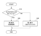
- FIG. 4 is a flowchart illustrating the operation of the robot display device 2.
- the selection unit 21 determines whether or not the camera 2b is facing the robot 3 and its peripheral device 4 (step S10).
- the selection unit 21 enables the second display by augmented reality and displays the second display on the display unit 20. Is displayed on the display screen 2a (step S20).
- the selection unit 21 enables the first display by virtual three-dimensional computer graphics, and the first display is enabled.
- the display is displayed on the display screen 2a by the display unit 20 (step S30). This completes this process.
- the following effects are achieved.
- the robot display device 2 the first display of the robot 3 or the robot 3 and its peripheral device 4 by three-dimensional computer graphics, and the robot 3 and its peripheral device 4 photographed by the camera 2b.
- a display unit 20 is provided so that the second display using the augmented reality of the above and the display unit 20 can be displayed in a switchable manner.
- the first display is enabled and the first display is displayed on the display unit 20, and the camera 2b is facing the robot 3 and its peripheral device 4.
- a selection unit 21 is further provided to enable the second display and display the second display on the display unit 20.
- the robot 3 or the robot 3 and its peripheral device 4 can be first displayed by three-dimensional computer graphics.
- the second display using the augmented reality of the robot 3 and its peripheral device 4 photographed by the camera 2b can be performed. That is, it is possible to provide a robot display device that can automatically switch between augmented reality display and three-dimensional computer graphics display.
- the robot display device 2 in the first display and the second display, as information about the robot 3 and its peripheral devices 4, the tool tip point of the robot 3, the teaching point of the program, and the robot 3 A configuration that displays at least one of a coordinate system, an operating range of each axis of the robot 3, a jog method of the robot 3, a trajectory of the robot 3, a position register, sensor information of the robot 3, and a reachable area of the robot 3. bottom. This enables intuitive understanding and confirmation.
- the present disclosure is not limited to the above embodiment, and various modifications and modifications can be made.
- the display device of the industrial machine of the present disclosure is applied to the robot display device 2, but the present invention is not limited to this.
- the robot 3 it can be applied to display devices of industrial machines such as various machine tools.
- Robot system Robot display device (display device for industrial machines) 2a Display screen 3 Robot (industrial machine) 4 Peripheral equipment 5 Control device 20 Display 21 Selection
Landscapes
- Engineering & Computer Science (AREA)
- Theoretical Computer Science (AREA)
- Physics & Mathematics (AREA)
- General Physics & Mathematics (AREA)
- General Engineering & Computer Science (AREA)
- Human Computer Interaction (AREA)
- Robotics (AREA)
- Mechanical Engineering (AREA)
- Computer Graphics (AREA)
- Computer Hardware Design (AREA)
- Software Systems (AREA)
- Automation & Control Theory (AREA)
- Manufacturing & Machinery (AREA)
- Manipulator (AREA)
- Numerical Control (AREA)
- Processing Or Creating Images (AREA)
Priority Applications (4)
| Application Number | Priority Date | Filing Date | Title |
|---|---|---|---|
| JP2022517673A JP7381729B2 (ja) | 2020-04-27 | 2021-04-21 | 産業機械の表示装置 |
| US17/996,586 US11978168B2 (en) | 2020-04-27 | 2021-04-21 | Display device for industrial machine |
| CN202180029833.9A CN115427201B (zh) | 2020-04-27 | 2021-04-21 | 工业机械的显示装置 |
| DE112021002550.3T DE112021002550T5 (de) | 2020-04-27 | 2021-04-21 | Anzeigevorrichtung für Industriemaschine |
Applications Claiming Priority (2)
| Application Number | Priority Date | Filing Date | Title |
|---|---|---|---|
| JP2020078214 | 2020-04-27 | ||
| JP2020-078214 | 2020-04-27 |
Publications (1)
| Publication Number | Publication Date |
|---|---|
| WO2021220915A1 true WO2021220915A1 (ja) | 2021-11-04 |
Family
ID=78373584
Family Applications (1)
| Application Number | Title | Priority Date | Filing Date |
|---|---|---|---|
| PCT/JP2021/016207 Ceased WO2021220915A1 (ja) | 2020-04-27 | 2021-04-21 | 産業機械の表示装置 |
Country Status (5)
| Country | Link |
|---|---|
| US (1) | US11978168B2 (https=) |
| JP (1) | JP7381729B2 (https=) |
| CN (1) | CN115427201B (https=) |
| DE (1) | DE112021002550T5 (https=) |
| WO (1) | WO2021220915A1 (https=) |
Cited By (1)
| Publication number | Priority date | Publication date | Assignee | Title |
|---|---|---|---|---|
| JPWO2022124398A1 (https=) * | 2020-12-10 | 2022-06-16 |
Citations (4)
| Publication number | Priority date | Publication date | Assignee | Title |
|---|---|---|---|---|
| WO2011080882A1 (ja) * | 2009-12-28 | 2011-07-07 | パナソニック株式会社 | 動作空間提示装置、動作空間提示方法およびプログラム |
| JP2012521855A (ja) * | 2009-03-31 | 2012-09-20 | インテュイティブ サージカル オペレーションズ, インコーポレイテッド | 手術ロボットの合成表現 |
| JP2016197393A (ja) * | 2015-04-03 | 2016-11-24 | キヤノン株式会社 | 情報処理装置、情報処理方法及びプログラム |
| JP2017100205A (ja) * | 2015-11-30 | 2017-06-08 | 株式会社デンソーウェーブ | バーチャルフェンス表示システム |
Family Cites Families (19)
| Publication number | Priority date | Publication date | Assignee | Title |
|---|---|---|---|---|
| US6917370B2 (en) * | 2002-05-13 | 2005-07-12 | Charles Benton | Interacting augmented reality and virtual reality |
| SE0203908D0 (sv) * | 2002-12-30 | 2002-12-30 | Abb Research Ltd | An augmented reality system and method |
| EP2672458A3 (en) * | 2012-06-06 | 2017-04-26 | Samsung Electronics Co., Ltd | Terminal, apparatus and method for providing an augmented reality service |
| WO2015185110A1 (en) * | 2014-06-03 | 2015-12-10 | Metaio Gmbh | Method and system for presenting a digital information related to a real object |
| JP6176214B2 (ja) * | 2014-09-25 | 2017-08-09 | 日本電気株式会社 | 記憶システム、記憶システム制御方法及び仮想テープ装置制御プログラム |
| JP2016107379A (ja) | 2014-12-08 | 2016-06-20 | ファナック株式会社 | 拡張現実対応ディスプレイを備えたロボットシステム |
| US9643314B2 (en) * | 2015-03-04 | 2017-05-09 | The Johns Hopkins University | Robot control, training and collaboration in an immersive virtual reality environment |
| KR20170005602A (ko) * | 2015-07-06 | 2017-01-16 | 삼성전자주식회사 | 증강현실 및 가상현실의 통합적 제공 방법 및 이를 사용하는 전자 장치 |
| JP6582921B2 (ja) * | 2015-11-26 | 2019-10-02 | 株式会社デンソーウェーブ | ロボットモニタシステム |
| US10748339B2 (en) * | 2016-06-03 | 2020-08-18 | A Big Chunk Of Mud Llc | System and method for implementing computer-simulated reality interactions between users and publications |
| EP3255511B1 (en) * | 2016-06-10 | 2021-03-31 | Sebastian Kummer | Method for planning or operating a facility |
| CN106128196A (zh) * | 2016-08-11 | 2016-11-16 | 四川华迪信息技术有限公司 | 基于增强现实和虚拟现实的网络在线教育系统及其实现方法 |
| US10378470B2 (en) * | 2017-06-12 | 2019-08-13 | Ford Global Technologies, Llc | Method and system for diagnosing boost pressure control |
| JP2019016044A (ja) * | 2017-07-04 | 2019-01-31 | 富士通株式会社 | 表示制御プログラム、表示制御方法及び表示制御装置 |
| JP6683671B2 (ja) * | 2017-11-24 | 2020-04-22 | ファナック株式会社 | ジョグ座標系を設定するロボットの制御装置 |
| EP3495936A1 (de) * | 2017-12-07 | 2019-06-12 | Siemens Aktiengesellschaft | Sichere brillenartige vorrichtung und verfahren |
| CN108646997A (zh) * | 2018-05-14 | 2018-10-12 | 刘智勇 | 一种虚拟及增强现实设备与其他无线设备进行交互的方法 |
| KR101944823B1 (ko) * | 2018-06-07 | 2019-02-07 | (주)영신디엔씨 | 증강현실 및 가상현실을 이용한 위치기반 지하시설물 탐지 시스템 |
| CN110238831B (zh) * | 2019-07-23 | 2020-09-18 | 青岛理工大学 | 基于rgb-d图像及示教器的机器人示教系统及方法 |
-
2021
- 2021-04-21 WO PCT/JP2021/016207 patent/WO2021220915A1/ja not_active Ceased
- 2021-04-21 DE DE112021002550.3T patent/DE112021002550T5/de active Pending
- 2021-04-21 CN CN202180029833.9A patent/CN115427201B/zh active Active
- 2021-04-21 US US17/996,586 patent/US11978168B2/en active Active
- 2021-04-21 JP JP2022517673A patent/JP7381729B2/ja active Active
Patent Citations (4)
| Publication number | Priority date | Publication date | Assignee | Title |
|---|---|---|---|---|
| JP2012521855A (ja) * | 2009-03-31 | 2012-09-20 | インテュイティブ サージカル オペレーションズ, インコーポレイテッド | 手術ロボットの合成表現 |
| WO2011080882A1 (ja) * | 2009-12-28 | 2011-07-07 | パナソニック株式会社 | 動作空間提示装置、動作空間提示方法およびプログラム |
| JP2016197393A (ja) * | 2015-04-03 | 2016-11-24 | キヤノン株式会社 | 情報処理装置、情報処理方法及びプログラム |
| JP2017100205A (ja) * | 2015-11-30 | 2017-06-08 | 株式会社デンソーウェーブ | バーチャルフェンス表示システム |
Cited By (4)
| Publication number | Priority date | Publication date | Assignee | Title |
|---|---|---|---|---|
| JPWO2022124398A1 (https=) * | 2020-12-10 | 2022-06-16 | ||
| WO2022124398A1 (ja) * | 2020-12-10 | 2022-06-16 | 三菱電機株式会社 | 遠隔制御マニピュレータシステムおよび遠隔制御支援システム |
| JP7224559B2 (ja) | 2020-12-10 | 2023-02-17 | 三菱電機株式会社 | 遠隔制御マニピュレータシステムおよび遠隔制御支援システム |
| US11926064B2 (en) | 2020-12-10 | 2024-03-12 | Mitsubishi Electric Corporation | Remote control manipulator system and remote control assistance system |
Also Published As
| Publication number | Publication date |
|---|---|
| US20230316668A1 (en) | 2023-10-05 |
| US11978168B2 (en) | 2024-05-07 |
| CN115427201B (zh) | 2025-09-19 |
| JP7381729B2 (ja) | 2023-11-15 |
| DE112021002550T5 (de) | 2023-03-02 |
| JPWO2021220915A1 (https=) | 2021-11-04 |
| CN115427201A (zh) | 2022-12-02 |
Similar Documents
| Publication | Publication Date | Title |
|---|---|---|
| US11173601B2 (en) | Teaching device for performing robot teaching operations and teaching method | |
| US10807240B2 (en) | Robot control device for setting jog coordinate system | |
| CN110476168B (zh) | 用于手部跟踪的方法和系统 | |
| US7557816B2 (en) | Image processing apparatus, method and computer-readable storage medium for generating and presenting an image of virtual objects including the operation panel viewed from the position and orientation of the viewpoint of the observer | |
| US10166673B2 (en) | Portable apparatus for controlling robot and method thereof | |
| US20160196692A1 (en) | Virtual lasers for interacting with augmented reality environments | |
| EP2875914A1 (en) | Robot simulator, robot teaching device and robot teaching method | |
| EP2923806A1 (en) | Robot control device, robot, robotic system, teaching method, and program | |
| JP6357023B2 (ja) | 情報処理プログラム、情報処理装置、情報処理装置の制御方法および情報処理システム | |
| CN103257812B (zh) | 一种调整显示输出的方法及电子设备 | |
| US20220331972A1 (en) | Robot Image Display Method, Recording Medium, And Robot Image Display System | |
| JP7381729B2 (ja) | 産業機械の表示装置 | |
| JP6710919B2 (ja) | ロボット操作装置 | |
| JP2009271851A (ja) | 情報処理装置、そのポインタ表示方法、およびコンピュータが実行可能なプログラム | |
| JP4856136B2 (ja) | 移動制御プログラム | |
| JP7712373B2 (ja) | 教示装置及びロボットシステム | |
| JP7768998B2 (ja) | 制御装置 | |
| KR20210072463A (ko) | 인간-머신 상호작용 방법 및 이를 위한 장치 | |
| EP3779893B1 (en) | Image processing system showing jig arrangement | |
| US20230062991A1 (en) | Operation system for industrial machinery | |
| JP2023017440A (ja) | 画像処理装置 | |
| JP7645145B2 (ja) | 教示データ修正装置 | |
| WO2026074620A1 (ja) | 制御装置、産業機械、及びコンピュータが読み取り可能な記憶媒体 | |
| WO2025102363A1 (en) | Method for controlling movement of robot, electronic device, and computer readable storage medium | |
| JP2004192306A (ja) | 表示位置変更装置、表示位置変更方法、表示位置変更プログラム及びそのプログラムを記録した記録媒体 |
Legal Events
| Date | Code | Title | Description |
|---|---|---|---|
| 121 | Ep: the epo has been informed by wipo that ep was designated in this application |
Ref document number: 21797404 Country of ref document: EP Kind code of ref document: A1 |
|
| ENP | Entry into the national phase |
Ref document number: 2022517673 Country of ref document: JP Kind code of ref document: A |
|
| 122 | Ep: pct application non-entry in european phase |
Ref document number: 21797404 Country of ref document: EP Kind code of ref document: A1 |
|
| WWG | Wipo information: grant in national office |
Ref document number: 202180029833.9 Country of ref document: CN |