WO2021220612A1 - 光学系、光学機器および光学系の製造方法 - Google Patents
光学系、光学機器および光学系の製造方法 Download PDFInfo
- Publication number
- WO2021220612A1 WO2021220612A1 PCT/JP2021/008532 JP2021008532W WO2021220612A1 WO 2021220612 A1 WO2021220612 A1 WO 2021220612A1 JP 2021008532 W JP2021008532 W JP 2021008532W WO 2021220612 A1 WO2021220612 A1 WO 2021220612A1
- Authority
- WO
- WIPO (PCT)
- Prior art keywords
- lens
- optical system
- group
- lens group
- object side
- Prior art date
- Legal status (The legal status is an assumption and is not a legal conclusion. Google has not performed a legal analysis and makes no representation as to the accuracy of the status listed.)
- Ceased
Links
Images


Classifications
-
- G—PHYSICS
- G02—OPTICS
- G02B—OPTICAL ELEMENTS, SYSTEMS OR APPARATUS
- G02B9/00—Optical objectives characterised both by the number of the components and their arrangements according to their sign, i.e. + or -
- G02B9/64—Optical objectives characterised both by the number of the components and their arrangements according to their sign, i.e. + or - having more than six components
-
- G—PHYSICS
- G02—OPTICS
- G02B—OPTICAL ELEMENTS, SYSTEMS OR APPARATUS
- G02B9/00—Optical objectives characterised both by the number of the components and their arrangements according to their sign, i.e. + or -
- G02B9/12—Optical objectives characterised both by the number of the components and their arrangements according to their sign, i.e. + or - having three components only
- G02B9/14—Optical objectives characterised both by the number of the components and their arrangements according to their sign, i.e. + or - having three components only arranged + - +
-
- G—PHYSICS
- G02—OPTICS
- G02B—OPTICAL ELEMENTS, SYSTEMS OR APPARATUS
- G02B13/00—Optical objectives specially designed for the purposes specified below
- G02B13/001—Miniaturised objectives for electronic devices, e.g. portable telephones, webcams, PDAs, small digital cameras
- G02B13/0015—Miniaturised objectives for electronic devices, e.g. portable telephones, webcams, PDAs, small digital cameras characterised by the lens design
- G02B13/005—Miniaturised objectives for electronic devices, e.g. portable telephones, webcams, PDAs, small digital cameras characterised by the lens design having spherical lenses only
-
- G—PHYSICS
- G02—OPTICS
- G02B—OPTICAL ELEMENTS, SYSTEMS OR APPARATUS
- G02B13/00—Optical objectives specially designed for the purposes specified below
- G02B13/02—Telephoto objectives, i.e. systems of the type + - in which the distance from the front vertex to the image plane is less than the equivalent focal length
-
- G—PHYSICS
- G02—OPTICS
- G02B—OPTICAL ELEMENTS, SYSTEMS OR APPARATUS
- G02B7/00—Mountings, adjusting means, or light-tight connections, for optical elements
- G02B7/02—Mountings, adjusting means, or light-tight connections, for optical elements for lenses
- G02B7/04—Mountings, adjusting means, or light-tight connections, for optical elements for lenses with mechanism for focusing or varying magnification
- G02B7/08—Mountings, adjusting means, or light-tight connections, for optical elements for lenses with mechanism for focusing or varying magnification adapted to co-operate with a remote control mechanism
Definitions
- the present invention relates to an optical system, an optical device, and a method for manufacturing the optical system.
- Patent Document 1 Conventionally, optical systems used for photographic cameras, electronic still cameras, video cameras, etc. have been proposed (see, for example, Patent Document 1).
- the optical system of the present disclosure is composed of a first lens group having a positive refractive power, a focusing group moving along the optical axis at the time of focusing, and a rear group in order from the object side, and the first lens.
- the lens group arranged on the object side with the largest air gap A in the group is defined as the first A lens group, and all of the following conditional expressions are satisfied.
- TL Total optical length of the optical system when in focus at infinity
- dA Distance on the optical axis of air spacing
- a dG1 Distance on the optical axis of the first lens group
- the optical system of the present disclosure is an optical system composed of a plurality of lenses, has at least one positive lens component and a negative lens N in order from the object side, and satisfies all of the following conditional expressions. 1.00 ⁇ FNo x (TL / f) 2 ⁇ 2.50 0.18 ⁇ dN / TL ⁇ 0.45
- FNo F value of the optical system at infinity TL: Total optical length of the optical system at infinity
- f Focal length of the optical system at infinity dN: From the surface of the optical system on the most object side Distance on the optical axis of the negative lens N to the object-side surface
- the optical system of the present disclosure is an optical system composed of a plurality of lenses, which has a positive lens component on the object side most, and is arranged on the object side most of the negative lenses arranged on the image side of the positive lens component. It has a negative lens N and satisfies all of the following conditional expressions. 1.00 ⁇ FNo x (TL / f) 2 ⁇ 2.50 0.18 ⁇ dN / TL ⁇ 0.45
- FNo F value of the optical system at infinity TL: Total optical length of the optical system at infinity f: Focal length of the optical system at infinity dN: From the surface of the optical system on the most object side Distance on the optical axis of the negative lens N to the object-side surface
- the method for manufacturing an optical system according to the present disclosure is a method for manufacturing an optical system composed of a plurality of lenses, in which the first lens group having a positive refractive power is arranged in order from the object side along the optical axis during focusing.
- the focusing group and the rear group are arranged, and the first A lens group is arranged on the object side with the largest air gap A in the first lens group, and all of the following conditional expressions are satisfied.
- the method for manufacturing an optical system of the present disclosure is a method for manufacturing an optical system composed of a plurality of lenses, in which at least one positive lens component and a negative lens N are arranged in order from the object side, and the following conditional expression is applied. Arrange everything to your satisfaction. 1.00 ⁇ FNo x (TL / f) 2 ⁇ 2.50 0.18 ⁇ dN / TL ⁇ 0.45
- FNo F value of the optical system at infinity TL: Total optical length of the optical system at infinity f: Focal length of the optical system at infinity dN: From the surface of the optical system on the most object side Distance on the optical axis of the negative lens N to the object-side surface
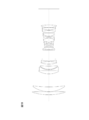
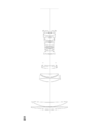
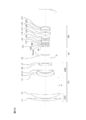
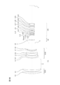
- FIG. 1A is a cross-sectional view of the optical system of the first embodiment when the infinity object is in focus.
- FIG. 1B is a cross-sectional view of the optical system of the first embodiment when the short-distance object is in focus.
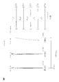
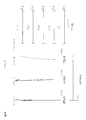
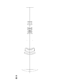
- FIG. 2 is an aberration diagram of the optical system of the first embodiment when the object is in focus at infinity.
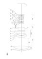
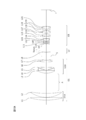
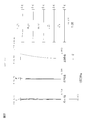
- FIG. 3A is a cross-sectional view of the optical system of the second embodiment when the infinity object is in focus.
- FIG. 3B is a cross-sectional view of the optical system of the second embodiment when the short-distance object is in focus.
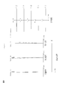
- FIG. 4 is an aberration diagram of the optical system of the second embodiment when the object is in focus at infinity.
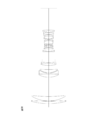
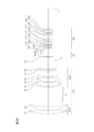
- FIG. 5A is a cross-sectional view of the optical system of the third embodiment when the infinity object is in focus.
- FIG. 5B is a cross-sectional view of the optical system of the third embodiment when the short-distance object is in focus.
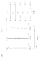
- FIG. 6 is an aberration diagram of the optical system of the third embodiment when the object is in focus at infinity.
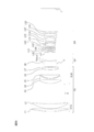
- FIG. 7A is a cross-sectional view of the optical system of the fourth embodiment when the infinity object is in focus.
- FIG. 7B is a cross-sectional view of the optical system of the fourth embodiment when the short-distance object is in focus.
- FIG. 8 is an aberration diagram of the optical system of the fourth embodiment when the object is in focus at infinity.
- FIG. 9A is a cross-sectional view of the optical system of the fifth embodiment when the infinity object is in focus.
- FIG. 9B is a cross-sectional view of the optical system of the fifth embodiment when the short-distance object is in focus.
- FIG. 10 is a diagram of various aberrations of the optical system of the fifth embodiment when the object is in focus at infinity.
- FIG. 11A is a cross-sectional view of the optical system of the sixth embodiment when the infinity object is in focus.
- FIG. 11B is a cross-sectional view of the optical system of the sixth embodiment when the short-distance object is in focus.
- FIG. 12 is a diagram of various aberrations of the optical system of the sixth embodiment when the object is in focus at infinity.
- FIG. 13A is a cross-sectional view of the optical system of the seventh embodiment when the infinity object is in focus.
- FIG. 13B is a cross-sectional view of the optical system of the seventh embodiment when the short-distance object is in focus.
- FIG. 14 is a diagram of various aberrations of the optical system of the seventh embodiment when the object is in focus at infinity.
- FIG. 15A is a cross-sectional view of the optical system of the eighth embodiment when the infinity object is in focus.
- FIG. 15B is a cross-sectional view of the optical system of the eighth embodiment when the short-distance object is in focus.
- FIG. 16 is a diagram of various aberrations of the optical system of the eighth embodiment when the infinity object is in focus.
- FIG. 17A is a cross-sectional view of the optical system of the ninth embodiment when the infinity object is in focus.
- FIG. 17B is a cross-sectional view of the optical system of the ninth embodiment when the short-distance object is in focus.
- FIG. 18 is a diagram of various aberrations of the optical system of the ninth embodiment when the object is in focus at infinity.
- FIG. 19A is a cross-sectional view of the optical system of the tenth embodiment when the infinity object is in focus.
- FIG. 19B is a cross-sectional view of the optical system of the tenth embodiment when the short-distance object is in focus.
- FIG. 20 is an aberration diagram of the optical system of the tenth embodiment when the infinity object is in focus.
- FIG. 21A is a cross-sectional view of the optical system of the eleventh embodiment when the infinity object is in focus.
- FIG. 21B is a cross-sectional view of the optical system of the eleventh embodiment when the short-distance object is in focus.
- FIG. 22 is a diagram of various aberrations of the optical system of the eleventh embodiment when the infinity object is in focus.
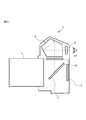
- FIG. 23 is a schematic view of a camera provided with the optical system of this embodiment.
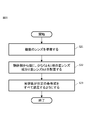
- FIG. 24 is a first flowchart showing an outline of a method for manufacturing an optical system according to the present embodiment.
- FIG. 25 is a second flowchart showing an outline of the method for manufacturing the optical system of the present embodiment.
- the optical system of the present embodiment is composed of a first lens group having a positive refractive power, a focusing group moving along the optical axis at the time of focusing, and a rear group in order from the object side.
- the lens group arranged on the object side with the largest air gap A in the lens group is defined as the first A lens group, and all of the following conditional expressions are satisfied.
- the optical system of the present embodiment is corrected by a lens on the image side of the first A lens group, and an optical system having both small size and light weight and good optical performance can be obtained. Further, the optical system of the present embodiment can be miniaturized by satisfying the conditional expression (1). Further, the optical system of the present embodiment can realize the weight reduction of the optical system by satisfying the conditional expression (2). In the optical system of the present embodiment, the effect of the present embodiment can be made more reliable by setting the upper limit value of the conditional expression (1) to 2.50. Further, in order to further ensure the effect of the present embodiment, the upper limit of the conditional expression (1) is set to 2.45, 2.40, 2.35, 2.30, 2.25, 2.20, and further 2. It is preferably .15.
- the effect of the present embodiment can be made more reliable by setting the lower limit value of the conditional expression (1) to 1.00. Further, in order to further ensure the effect of the present embodiment, it is preferable to set the lower limit values of the conditional expression (1) to 1.10, 1.20, 1.25, 1.30, and further 1.35.
- the effect of this embodiment can be made more reliable by setting the upper limit value of the conditional expression (2) to 0.85. Further, in order to further ensure the effect of the present embodiment, it is preferable to set the upper limit values of the conditional expression (2) to 0.80, 0.76, 0.73, 0.70, and further 0.68.
- the effect of the present embodiment can be made more reliable by setting the lower limit value of the conditional expression (2) to 0.30. Further, in order to further ensure the effect of the present embodiment, it is preferable to set the lower limit values of the conditional expression (2) to 0.31, 0.33, and further 0.35.
- the optical system of the present embodiment is composed of a first lens group having a positive refractive power, a focusing group moving along the optical axis at the time of focusing, and a rear group in order from the object side.
- the lens group arranged on the object side with the largest air gap A in the lens group is defined as the first A lens group, and all of the following conditional expressions are satisfied.
- TL Total optical length of the optical system when in focus at infinity
- f Focal length of the optical system when in focus at infinity
- dA Distance on the optical axis of air spacing
- a dG1 Distance on the optical axis of the first lens group
- the optical system of the present embodiment is corrected by a lens on the image side of the first A lens group, and an optical system having both small size and light weight and good optical performance can be obtained. Further, the optical system of the present embodiment can be miniaturized by satisfying the conditional expression (3). Further, the optical system of the present embodiment can realize the weight reduction of the optical system by satisfying the conditional expression (2).
- the total length of the optical system can be prevented from becoming too long by making the ratio of the total optical length of the optical system to the focal length of the optical system smaller than the upper limit value. Further, by setting the upper limit value of the conditional expression (3) to 0.80, the effect of the present embodiment can be made more reliable. Further, in order to further ensure the effect of the present embodiment, it is preferable to set the upper limit values of the conditional expression (3) to 0.78, 0.76, 0.74, 0.72, and further 0.70.
- the optical system of the present embodiment can satisfactorily correct curvature of field by making the ratio of the total optical length of the optical system to the focal length of the optical system larger than the lower limit value. Further, by setting the lower limit value of the conditional expression (3) to 0.30, the effect of the present embodiment can be made more reliable. Further, in order to further ensure the effect of the present embodiment, it is preferable to set the lower limit values of the conditional expression (3) to 0.33, 0.36, 0.40, 0.42, and further 0.44.
- the effect of this embodiment can be made more reliable by setting the upper limit value of the conditional expression (2) to 0.85. Further, in order to further ensure the effect of the present embodiment, it is preferable to set the upper limit values of the conditional expression (2) to 0.80, 0.76, 0.73, 0.70, and further 0.68.
- the effect of the present embodiment can be made more reliable by setting the lower limit value of the conditional expression (2) to 0.30. Further, in order to further ensure the effect of the present embodiment, it is preferable to set the lower limit values of the conditional expression (2) to 0.31, 0.33, and further 0.35.
- the optical system of the present embodiment is an optical system composed of a plurality of lenses, has at least one positive lens component and a negative lens N in order from the object side, and satisfies all of the following conditional expressions.
- FNo F value of the optical system at infinity TL: Total optical length of the optical system at infinity
- f Focal length of the optical system at infinity
- dN Negative lens from the most object side of the optical system Distance on the optical axis to the side of the object of N
- the optical system of the present embodiment can be made compact and lightweight on the object side of the optical system, and has various aberrations on the image side of the optical system. It is possible to obtain good imaging performance by performing correction.
- a "lens component" means a single lens or a junction lens.
- the effect of the present embodiment can be made more reliable by setting the upper limit value of the conditional expression (1) to 2.50.
- the upper limit of the conditional expression (1) is set to 2.45, 2.40, 2.35, 2.30, 2.25, 2.20, and further 2. It is preferably .15.
- the effect of the present embodiment can be made more reliable by setting the lower limit value of the conditional expression (1) to 1.00. Further, in order to further ensure the effect of the present embodiment, it is preferable to set the lower limit values of the conditional expression (1) to 1.10, 1.20, 1.25, 1.30, and further 1.35.
- the effect of this embodiment can be made more reliable by setting the upper limit value of the conditional expression (4) to 0.45. Further, in order to further ensure the effect of the present embodiment, it is preferable to set the upper limit values of the conditional expression (4) to 0.42, 0.40, 0.38, and further 0.36.
- the effect of the present embodiment can be made more reliable by setting the lower limit value of the conditional expression (4) to 0.18. Further, in order to further ensure the effect of the present embodiment, it is preferable to set the lower limit values of the conditional expression (4) to 0.19, 0.20, 0.21 and further 0.22.
- the optical system of the present embodiment is an optical system composed of a plurality of lenses, has a positive lens component on the object side most, and is arranged on the object side most of the negative lenses arranged on the image side from the positive lens component. It has a negative lens N and satisfies all of the following conditional expressions. (1) 1.00 ⁇ FNo ⁇ (TL / f) 2 ⁇ 2.50 (4) 0.18 ⁇ dN / TL ⁇ 0.45
- FNo F value of the optical system at infinity TL: Total optical length of the optical system at infinity f: Focal length of the optical system at infinity dN: From the surface of the optical system on the most object side Distance on the optical axis of the negative lens N to the object-side surface
- the optical system of the present embodiment can be made compact and lightweight on the object side of the optical system, and has various aberrations on the image side of the optical system. It is possible to obtain good imaging performance by performing correction.
- the effect of the present embodiment can be made more reliable by setting the upper limit value of the conditional expression (1) to 2.50.
- the upper limit of the conditional expression (1) is set to 2.45, 2.40, 2.35, 2.30, 2.25, 2.20, and further 2. It is preferably .15.
- the effect of the present embodiment can be made more reliable by setting the lower limit value of the conditional expression (1) to 1.00. Further, in order to further ensure the effect of the present embodiment, it is preferable to set the lower limit values of the conditional expression (1) to 1.10, 1.20, 1.25, 1.30, and further 1.35.
- the effect of this embodiment can be made more reliable by setting the upper limit value of the conditional expression (4) to 0.45. Further, in order to further ensure the effect of the present embodiment, it is preferable to set the upper limit values of the conditional expression (4) to 0.42, 0.40, 0.38, and further 0.36.
- the effect of the present embodiment can be made more reliable by setting the lower limit value of the conditional expression (4) to 0.18. Further, in order to further ensure the effect of the present embodiment, it is preferable to set the lower limit values of the conditional expression (4) to 0.19, 0.20, 0.21 and further 0.22.
- the optical system of the present embodiment is composed of a first lens group, a focusing group that moves along the optical axis at the time of focusing, and a rear group in order from the object side. It is preferable to have the first A lens group arranged on the object side with the largest air spacing A in the first lens group, and satisfy the following conditional expression. (2) 0.30 ⁇ dA / dG1 ⁇ 0.85 However, dA: Distance on the optical axis of the air interval A dG1: Distance on the optical axis of the first lens group
- the optical system of the present embodiment can further reduce the weight of the entire optical system by satisfying the conditional expression (2).
- the effect of the present embodiment can be made more reliable by setting the upper limit value of the conditional expression (2) to 0.85. Further, in order to further ensure the effect of the present embodiment, it is preferable to set the upper limit values of the conditional expression (2) to 0.80, 0.76, 0.73, 0.70, and further 0.68.
- the effect of the present embodiment can be made more reliable by setting the lower limit value of the conditional expression (2) to 0.30. Further, in order to further ensure the effect of the present embodiment, it is preferable to set the lower limit values of the conditional expression (2) to 0.31, 0.33, and further 0.35.
- optical system of the present embodiment preferably satisfies the following conditional expression. (3) 0.30 ⁇ TL / f ⁇ 0.80
- the optical system of the present embodiment can achieve both miniaturization of the optical system and good curvature of field correction by satisfying the conditional expression (3).
- the total length of the optical system can be prevented from becoming too long by making the ratio of the total optical length of the optical system to the focal length of the optical system smaller than the upper limit value.
- the upper limit value of the conditional expression (3) it is preferable to set the upper limit values of the conditional expression (3) to 0.78, 0.76, 0.74, 0.72, and further 0.70.
- the optical system of the present embodiment can satisfactorily correct curvature of field by making the ratio of the total optical length of the optical system to the focal length of the optical system larger than the lower limit value. Further, by setting the lower limit value of the conditional expression (3) to 0.30, the effect of the present embodiment can be made more reliable. Further, in order to further ensure the effect of the present embodiment, it is preferable to set the lower limit values of the conditional expression (3) to 0.33, 0.36, 0.40, 0.42, and further 0.44.
- the first lens group has a positive lens component and a negative lens N.
- the first lens group is composed of a first lens group, a focusing group that moves along the optical axis at the time of focusing, and a rear group in order from the object side. It has a first A lens group arranged on the object side and a first B lens group arranged on the image side with the largest air gap A in the first lens group, and satisfies the following conditional expression. preferable. (5) -2.00 ⁇ f1A / f1B ⁇ 0.30 However, f1A: Focal length of the 1st A lens group f1B: Focal length of the 1st B lens group
- the optical system of the present embodiment can satisfactorily correct various aberrations by satisfying the conditional expression (5).
- the power of the first B lens group is not excessively positively strengthened by making the ratio of the focal length of the first A lens group to the focal length of the first B lens group smaller than the upper limit value.
- Spherical aberration and the like can be satisfactorily corrected.
- the upper limit value of the conditional expression (5) it is preferable to set the upper limit values of the conditional expression (5) to 0.25, 0.25, 0.15, 0.10, and further 0.07.
- the optical system of the present embodiment by making the ratio of the focal length of the 1st A lens group to the focal length of the 1st B lens group larger than the lower limit value, the power of the 1st B lens group does not become excessively negative. , Coma aberration and the like can be satisfactorily corrected. Further, by setting the lower limit value of the conditional expression (5) to ⁇ 2.00, the effect of the present embodiment can be made more reliable. Further, in order to further ensure the effect of the present embodiment, the lower limit values of the conditional expression (5) are set to -1.60, -1.30, -1.00, -0.80, and further -0.60. It is preferable to do so.
- the optical system of the present embodiment is composed of a first lens group, a focusing group that moves along the optical axis at the time of focusing, and a rear group in order from the object side. It is preferable to have the first A lens group arranged on the object side with the largest air spacing A in the first lens group, and satisfy the following conditional expression. (6) 0.10 ⁇ f1A / f ⁇ 0.60 However, f1A: Focal length of the 1st A lens group
- the optical system of the present embodiment can achieve both weight reduction and good coma aberration correction by satisfying the conditional expression (6).
- the optical system of the present embodiment by making the ratio of the focal length of the first A lens group to the focal length of the optical system smaller than the upper limit value, the power of the first A lens group is not weakened, and the first A lens group is used. Since the diameter of the first lens group to be removed can be reduced, the weight of the optical system can be reduced. Further, by setting the upper limit value of the conditional expression (6) to 0.60, the effect of the present embodiment can be made more reliable. Further, in order to further ensure the effect of the present embodiment, it is preferable to set the upper limit values of the conditional expression (6) to 0.57, 0.55, 0.52, 0.48, and further 0.45.
- the power of the first A lens group is not increased by making the ratio of the focal length of the first A lens group to the focal length of the optical system larger than the lower limit value, so that coma aberration is satisfactorily corrected. can do.
- the lower limit value of the conditional expression (6) is set to 0.10, the effect of the present embodiment can be made more reliable.
- the optical system of the present embodiment is composed of a first lens group, a focusing group that moves along the optical axis at the time of focusing, and a rear group in order from the object side. It is preferable to have a first B lens group arranged on the image side with the largest air spacing A in the first lens group, and satisfy the following conditional expression. (7) 0.40 ⁇ dB / dG1 ⁇ 0.85 However, dB: Distance on the optical axis from the surface on the most object side of the optical system to the surface on the most object side of the first B lens group dG1: Distance on the optical axis of the first lens group
- the optical system of the present embodiment can achieve both weight reduction and good spherical aberration correction by satisfying the conditional expression (7).
- spherical aberration can be satisfactorily corrected by making the value of the conditional expression (7) smaller than the upper limit value.
- the upper limit value of the conditional expression (7) it is preferable to set the upper limit values of the conditional expression (7) to 0.82, 0.80, 0.78, 0.76, and further 0.74.
- the diameter of the first B lens group can be reduced by making the value of the conditional expression (7) larger than the lower limit value, so that the optical system can be made lighter. Further, by setting the lower limit value of the conditional expression (7) to 0.40, the effect of the present embodiment can be made more reliable. Further, in order to further ensure the effect of the present embodiment, it is preferable to set the lower limit values of the conditional expression (7) to 0.44, 0.47, 0.50, 0.52, and further 0.54.
- the first lens group is composed of a first lens group, a focusing group that moves along the optical axis at the time of focusing, and a rear group in order from the object side. It is preferable that the first A lens group has a first A lens group arranged on the object side with the largest air gap A in the first lens group, and the first A lens group consists of two or less positive lenses.
- the optical system of the present embodiment can be reduced in weight by having such a configuration.
- the optical system of the present embodiment is composed of a first lens group, a focusing group that moves along the optical axis at the time of focusing, and a rear group in order from the object side. It is preferable to have the first A lens group arranged on the object side with the largest air spacing A in the first lens group, and satisfy the following conditional expression. (8) 0.80 ⁇ fL1 / fL2 ⁇ 3.30 However, fL1: Focal length of the first lens placed closest to the object side in the first A lens group fL2: Focal length of the second lens placed second from the object side in the first A lens group
- the optical system of the present embodiment can satisfactorily correct spherical aberration and coma by satisfying the conditional expression (8).
- the optical system of the present embodiment by making the ratio between the focal length of the first lens and the focal length of the second lens smaller than the upper limit value, the power of the first lens is not too weak and the coma aberration is satisfactorily improved. It can be corrected.
- the upper limit value of the conditional expression (8) by setting the upper limit value of the conditional expression (8) to 3.30, the effect of the present embodiment can be made more reliable. Further, in order to further ensure the effect of the present embodiment, it is preferable to set the upper limit value of the conditional expression (8) to 3.20, 3.10, 3.00, 2.90, and further 2.80.
- the optical system of the present embodiment by making the ratio of the focal length of the first lens to the focal length of the second lens larger than the lower limit value, the power of the first lens does not become too strong and the spherical aberration is satisfactorily improved. It can be corrected. Further, by setting the lower limit value of the conditional expression (8) to 0.80, the effect of the present embodiment can be made more reliable. Further, in order to further ensure the effect of the present embodiment, it is preferable to set the lower limit values of the conditional expression (8) to 0.85, 0.90, 0.95, 1.00, and further 1.05.
- the first lens group is composed of a first lens group, a focusing group that moves along the optical axis at the time of focusing, and a rear group in order from the object side. It has a first A lens group arranged on the object side and a first B lens group arranged on the image side with the largest air gap A in the first lens group, and the first B lens group has the following conditions. It is preferable to have at least one positive lens Z that satisfies the formula.
- the optical system of the present embodiment can satisfactorily correct the secondary dispersion of axial chromatic aberration by making the value of the conditional expression (9) larger than the lower limit value. Further, by setting the lower limit value of the conditional expression (9) to 60.00, the effect of the present embodiment can be made more reliable. Further, in order to further ensure the effect of the present embodiment, it is preferable to set the lower limit values of the conditional expression (9) to 62.00, 63.00, 64.00, 65.00, and further 66.00.
- the optical system of the present embodiment is composed of a first lens group, a focusing group that moves along the optical axis at the time of focusing, and a rear group in order from the object side. It is preferable to have the first A lens group arranged on the object side with the largest air spacing A in the first lens group, and satisfy the following conditional expression. (10) 55.00 ⁇ d1Aave However, ⁇ d1Aave: Average value of Abbe numbers based on the d-line of the lenses included in the 1st A lens group
- the optical system of the present embodiment can satisfactorily correct axial chromatic aberration and chromatic aberration of magnification by making the value of the conditional expression (10) larger than the lower limit value. Further, by setting the lower limit value of the conditional expression (10) to 55.00, the effect of the present embodiment can be made more reliable. Further, in order to further ensure the effect of the present embodiment, it is preferable to set the lower limit values of the conditional expression (10) to 60.00, 65.00, 70.00, 75.00, and further 80.00.
- the optical system of the present embodiment is composed of a first lens group, a focusing group that moves along the optical axis at the time of focusing, and a rear group in order from the object side. It has a first B lens group arranged on the image side with the largest air gap A in the first lens group, and the first B lens group has at least one positive lens Z that satisfies all of the following conditional expressions. Is preferable.
- ndLZ Refraction coefficient of the positive lens Z with respect to the d-line
- ⁇ dLZ Abbe number ⁇ gFLZ based on the d-line of the positive lens
- ⁇ gFLZ (ngLZ-nFLZ) / (nFLZ-nCLZ) defined by the following equation.
- the optical system of the present embodiment can satisfactorily correct various aberrations.
- the value of the conditional expression (11) smaller than the upper limit value, the Petzval sum does not become too small, and the curvature of field can be satisfactorily corrected.
- the upper limit value of the conditional expression (11) it is preferable to set the upper limit values of the conditional expression (11) to 2.10, 2.09, 2.08, 2.07, and further 2.06.
- the optical system of the present embodiment can satisfactorily correct the secondary dispersion of axial chromatic aberration by making the value of the conditional expression (12) smaller than the upper limit value. Further, by setting the upper limit value of the conditional expression (12) to 35.00, the effect of the present embodiment can be made more reliable. Further, in order to further ensure the effect of the present embodiment, it is preferable to set the upper limit value of the conditional expression (12) to 33.00, 31.00, 30.50, 30.00, and further 29.50.
- the optical system of the present embodiment can satisfactorily correct the secondary dispersion of axial chromatic aberration by making the value of the conditional expression (13) larger than the lower limit value. Further, by setting the upper limit value of the conditional expression (13) to 0.702, the effect of the present embodiment can be made more reliable. Further, in order to further ensure the effect of the present embodiment, it is preferable to set the upper limit values of the conditional expression (13) to 0.704, 0.707, 0.710, 0.712, and further 0.715.
- the optical system of the present embodiment is composed of a first lens group, a focusing group that moves along the optical axis at the time of focusing, and a rear group in order from the object side. It is preferable to have the first A lens group arranged on the object side with the largest air spacing A in the first lens group, and satisfy the following conditional expression. (14) 0.00 ⁇ (L1R2 + L1R1) / (L1R2-L1R1) ⁇ 3.00
- L1R1 Radius of curvature of the surface of the first lens located closest to the object on the object side
- L1R2 Radius of curvature of the surface of the first lens on the image side
- the optical system of the present embodiment can satisfactorily correct spherical aberration and coma by satisfying the conditional expression (14).
- spherical aberration can be satisfactorily corrected by making the value of the conditional expression (14) smaller than the upper limit value.
- the upper limit value of the conditional expression (14) it is preferable to set the upper limit values of the conditional expression (14) to 2.70, 2.50, 2.20, 2.00, and further 1.80.
- the optical system of the present embodiment can satisfactorily correct coma by making the value of the conditional expression (14) larger than the lower limit value. Further, by setting the lower limit value of the conditional expression (14) to 0.00, the effect of the present embodiment can be made more reliable. Further, in order to further ensure the effect of the present embodiment, it is preferable to set the lower limit values of the conditional expression (14) to 0.20, 0.40, 0.50, 0.60, and further 0.70.
- the optical system of the present embodiment is composed of a first lens group, a focusing group that moves along the optical axis at the time of focusing, and a rear group in order from the object side. It is preferable to have the first A lens group arranged on the object side with the largest air spacing A in the first lens group, and satisfy the following conditional expression. (15) 0.00 ⁇ (L2R2 + L2R1) / (L2R2-L2R1) ⁇ 3.50
- L2R1 Radius of curvature of the side of the object of the second lens arranged second from the object side in the first A lens group
- L2R2 Radius of curvature of the side of the image of the second lens
- the optical system of the present embodiment can satisfactorily correct spherical aberration and coma by satisfying the conditional expression (15).
- spherical aberration can be satisfactorily corrected by making the value of the conditional expression (15) smaller than the upper limit value.
- the upper limit value of the conditional expression (14) it is preferable to set the upper limit values of the conditional expression (15) to 3.20, 3.00, 2.80, 2.60, and further 2.40.
- the optical system of the present embodiment can satisfactorily correct coma by making the value of the conditional expression (15) larger than the lower limit value. Further, by setting the lower limit value of the conditional expression (15) to 0.00, the effect of the present embodiment can be made more reliable. Further, in order to further ensure the effect of the present embodiment, it is preferable to set the lower limit values of the conditional expression (15) to 0.20, 0.50, 0.80, 1.00, and further 1.20.
- the optical system of the present embodiment is composed of a first lens group, a focusing group that moves along the optical axis at the time of focusing, and a rear group in order from the object side, and satisfies the following conditional expression. It is preferable to do so.
- f1 Focal length of the first lens group
- the optical system of the present embodiment can achieve both miniaturization and good spherical aberration correction by satisfying the conditional expression (16).
- the power of the first lens group is not too weak by making the ratio of the focal length of the first lens group to the focal length of the optical system smaller than the upper limit value. Miniaturization is possible. Further, by setting the upper limit value of the conditional expression (16) to 0.60, the effect of the present embodiment can be made more reliable. Further, in order to further ensure the effect of the present embodiment, it is preferable to set the upper limit values of the conditional expression (16) to 0.56, 0.53, 0.50, 0.48, and further 0.45.
- the value of the conditional expression (16) is made larger than the lower limit value, so that spherical aberration can be satisfactorily corrected. Further, by setting the lower limit value of the conditional expression (16) to 0.10, the effect of the present embodiment can be made more reliable. Further, in order to further ensure the effect of the present embodiment, it is preferable to set the lower limit values of the conditional expression (16) to 0.14, 0.18, 0.22, 0.25, and further 0.28.
- the optical system of the present embodiment is composed of a first lens group, a focusing group that moves along the optical axis at the time of focusing, and a rear group in order from the object side, and satisfies the following conditional expression. It is preferable to do so. (17) 0.20 ⁇ (-fF) / f1 ⁇ 0.85 However, fF: Focal length of the focusing group f1: Focal length of the first lens group
- the optical system of the present embodiment can satisfactorily correct various spherical aberrations from infinity to a close distance by satisfying the conditional expression (17).
- the optical system of the present embodiment by making the ratio of the focal length of the focusing group to the focal length of the first lens group smaller than the upper limit value, the power of the focusing group is not too weak, so that the curvature of field is formed. Fluctuations can be suppressed.
- the upper limit value of the conditional expression (17) to 0.85, the effect of the present embodiment can be made more reliable.
- the optical system of the present embodiment by making the ratio of the focal length of the focusing group to the focal length of the first lens group larger than the lower limit value, the power of the focusing group does not become too strong, so that axial chromatic aberration Fluctuations can be suppressed. Further, by setting the lower limit value of the conditional expression (17) to 0.20, the effect of the present embodiment can be made more reliable. Further, in order to further ensure the effect of the present embodiment, it is preferable to set the lower limit values of the conditional expression (17) to 0.24, 0.28, 0.32, 0.36, and further 0.40.
- the optical system of the present embodiment is composed of a first lens group, a focusing group that moves along the optical axis at the time of focusing, and a rear group in order from the object side, and satisfies the following conditional expression. It is preferable to do so.
- fF Focal length of the focusing group
- fR Focal length of the rear group
- the optical system of the present embodiment can satisfactorily correct various aberrations by satisfying the conditional expression (18).
- the value of the conditional expression (18) smaller than the upper limit value, the power of the focusing group does not become too weak, so that the curvature of field can be satisfactorily corrected.
- the upper limit value of the conditional expression (18) it is preferable to set the upper limit values of the conditional expression (18) to 0.50, 0.40, 0.30, 0.20, and further 0.10.
- the optical system of the present embodiment by making the value of the conditional expression (18) larger than the lower limit value, the power of the focusing group does not become too strong, so that the chromatic aberration of magnification can be satisfactorily corrected. Further, by setting the lower limit value of the conditional expression (18) to -1.50, the effect of the present embodiment can be made more reliable. Further, in order to further ensure the effect of the present embodiment, the lower limit values of the conditional expression (18) are set to -1.40, -1.30, -1.20, -1.10, and further -1.00. It is preferable to do so.
- the optical system of the present embodiment is composed of a first lens group, a focusing group that moves along the optical axis at the time of focusing, and a rear group in order from the object side, and satisfies the following conditional expression. It is preferable to do so. (19) 0.30 ⁇ dF / TL ⁇ 0.70 However, dF: Distance on the optical axis from the most object-side surface of the optical system to the most object-side surface of the focusing group
- the optical system of the present embodiment can achieve both high-speed focusing and suppression of curvature of field by reducing the weight of the focusing group.
- the value of the conditional expression (19) smaller than the upper limit value, the position of the focusing group is not too far behind, and the fluctuation of the curvature of field can be suppressed.
- the upper limit value of the conditional expression (19) it is preferable to set the upper limit values of the conditional expression (19) to 0.67, 0.64, 0.61, 0.58, and further 0.56.
- the position of the focusing group is not too forward, and the focusing group can be reduced in weight. Further, by setting the lower limit value of the conditional expression (19) to 0.30, the effect of the present embodiment can be made more reliable. Further, in order to further ensure the effect of the present embodiment, it is preferable to set the lower limit values of the conditional expression (19) to 0.32, 0.34, 0.36, 0.38, and further 0.40.
- the optical system of the present embodiment is composed of a first lens group, a focusing group that moves along the optical axis at the time of focusing, and a rear group in order from the object side, and satisfies the following conditional expression. It is preferable to do so.
- ⁇ dFave Average Abbe number based on the d-line of the lens included in the focusing group
- the optical system of the present embodiment can satisfactorily correct axial chromatic aberration from infinity to a close distance by making the value of the conditional expression (20) larger than the lower limit value. Further, by setting the lower limit value of the conditional expression (20) to 40.00, the effect of the present embodiment can be made more reliable. Further, in order to further ensure the effect of the present embodiment, it is preferable to set the lower limit value of the conditional expression (20) to 50.00, 55.00, 60.00, 65.00, and further 70.00.
- optical system of the present embodiment preferably satisfies the following conditional expression. (21) 1.00 ° ⁇ 2 ⁇ ⁇ 20.00 ° However, 2 ⁇ : Full angle of view of the optical system
- Conditional expression (21) sets an appropriate value for the total angle of view of the optical system of this embodiment.
- various aberration fluctuations such as coma, curvature of field, and distortion due to focusing can be suppressed.
- the upper limit value of the conditional expression (21) is set to 20.00 °, the effect of the present embodiment can be made more reliable.
- the upper limit values of the conditional expression (21) are set to 18.00 °, 16.00 °, 14.00 °, 12.00 °, and further 10.00 °. It is preferable to do so.
- the lower limit value of the conditional expression (21) is set to 1.00 °, the effect of the present embodiment can be made more reliable. Further, in order to further ensure the effect of the present embodiment, the lower limit values of the conditional expression (21) are set to 1.50 °, 2.00 °, 2.20 °, 2.50 °, and further 2.80 °. It is preferable to do so.
- optical system of the present embodiment preferably satisfies the following conditional expression. (22) 0.075 ⁇ Bf / f ⁇ 0.185
- Bf Back focus of optical system
- the optical system of the present embodiment can achieve both miniaturization and weight reduction by satisfying the conditional expression (22).
- the optical system of the present embodiment by making the ratio of the back focus of the optical system to the focal length smaller than the upper limit value, the back focus does not become too long and the total length can be shortened.
- the upper limit value of the conditional expression (22) it is preferable to set the upper limit values of the conditional expression (22) to 0.180, 0.175, 0.170, 0.165, and further 0.160.
- the back focus of the optical system to the focal length by making the ratio of the back focus of the optical system to the focal length larger than the lower limit value, the back focus can be appropriately secured and the weight of the optical system can be reduced. Further, by setting the lower limit value of the conditional expression (22) to 0.075, the effect of the present embodiment can be made more reliable. Further, in order to further ensure the effect of the present embodiment, it is preferable to set the lower limit values of the conditional expression (22) to 0.080, 0.082, 0.085, 0.088, and further 0.090.
- the first lens group, the focusing group that moves along the optical axis at the time of focusing, and the rear group are composed in order from the object side, and the rear group is image blurring. It is preferable to have a group of anti-vibration lenses that can be moved so as to have a component in the direction perpendicular to the optical axis in order to correct the problem.
- the optical system of the present embodiment can satisfactorily correct image blur.
- the optical device of this embodiment has an optical system having the above-described configuration. As a result, it is possible to realize an optical device that is compact and lightweight and has good imaging performance.
- the method for manufacturing an optical system according to the present embodiment is a method for manufacturing an optical system composed of a plurality of lenses, in which the first lens group having a positive refractive power is arranged in order from the object side to the optical axis at the time of focusing.
- the in-focus group moving along the line and the rear group are arranged, and the first A lens group is arranged on the object side with the largest air spacing A in the first lens group, and all of the following conditional expressions are satisfied. Arrange to do so.
- the method for manufacturing an optical system is a method for manufacturing an optical system composed of a plurality of lenses, in which at least one positive lens component and a negative lens N are arranged in order from the object side, and the following conditional expression is used.
- FNo F value of the optical system at infinity TL: Total optical length of the optical system at infinity f: Focal length of the optical system at infinity dN: Negative lens from the most object side of the optical system Distance on the optical axis to the side of the object of N
- optical system manufacturing method it is possible to manufacture an optical system that is compact and lightweight and has good imaging performance.
- FIG. 1A is a cross-sectional view of the optical system of the first embodiment when the object is in focus at infinity
- FIG. 1B is a cross-sectional view of the optical system of the first embodiment when the object is in focus at a short distance.
- the optical system of this embodiment includes a first lens group G1 having a positive refractive power, a focusing group GF having a negative refractive power, and a rear group GR having a negative refractive power in order from the object side. doing.
- the aperture diaphragm S is arranged between the first lens group G1 and the focusing group GF.
- the first lens group G1 has a positive refractive power arranged on the object side and a negative refractive power arranged on the image side with the largest air gap A in the first lens group. It has the first B lens group G1B which has.
- the first A lens group G1A is composed of a positive meniscus lens L1 having a convex surface facing the object side and a positive meniscus lens L2 having a convex surface facing the object side in order from the object side.
- the first B lens group G1B includes a positive meniscus lens L3 having a convex surface facing the object side and a negative meniscus lens L4 having a convex surface facing the object side, and a positive lens having a convex surface facing the object side, in order from the object side. It is composed of a meniscus lens L5, a biconvex positive lens L6, and a biconcave negative lens L7.
- the focusing group GF consists of a negative meniscus lens L8 with a convex surface facing the object side.
- the rear group GR is a positive meniscus lens L9 with a convex surface facing the image side, a junction negative lens of a biconvex positive lens L10 and a biconcave negative lens L11, and a biconcave negative lens in order from the object side.
- An image sensor (not shown) composed of a CCD, CMOS, or the like is arranged on the image plane I.
- the optical system of this embodiment focuses by moving the focusing group GF along the optical axis.
- the focusing group GF is moved from the object side to the image side when focusing on a short-distance object from the state of being in focus at infinity.
- the negative lens and the negative lens L12 which are the junction of the positive lens L10 and the negative lens L11, are components in the direction perpendicular to the optical axis in order to correct the image blur. It is configured as a group of anti-vibration lenses that can be moved so as to have.
- the positive meniscus lens L1 corresponds to the first lens
- the positive meniscus lens L2 corresponds to the second lens
- the negative meniscus lens L4 corresponds to the negative lens N
- the positive lens L6 corresponds to the positive lens Z.
- dA is the distance on the optical axis between the image-side surface of the positive meniscus lens L2 and the object-side surface of the positive meniscus lens L3.
- dG1 is the distance on the optical axis between the surface of the positive meniscus lens L1 on the object side and the surface of the negative lens L7 on the image side.
- dB is the distance on the optical axis between the object-side surface of the positive meniscus lens L1 and the object-side surface of the positive meniscus lens L3.
- dN is a distance on the optical axis between the object-side surface of the positive meniscus lens L1 and the object-side surface of the negative meniscus lens L4.
- Table 1 below lists the values of the specifications of the optical system of this embodiment.
- f is the focal length of the optical system at infinity focus
- Fno is the F value of the optical system at infinity focus
- TL is the total optical length of the optical system at infinity focus
- Bf is the optical system. Indicates the back focus of.
- m is the order of the optical planes counted from the object side
- r is the radius of curvature
- d is the plane spacing
- nd is the refractive index for the d line (wavelength 587.6 nm)
- ⁇ d is the Abbe number for the d line. show.
- the radius of curvature r ⁇ indicates a plane.
- the unit of focal length f, radius of curvature r and other lengths shown in Table 1 is "mm".
- the optical system is not limited to this because the same optical performance can be obtained even if the optical system is proportionally expanded or decreased.
- FIG. 2 is a diagram of various aberrations of the optical system of the first embodiment when the infinity object is in focus.
- FNO indicates F value
- Y indicates image height
- the spherical aberration diagram shows the value of the F value corresponding to the maximum aperture
- the astigmatism diagram and the distortion diagram show the maximum value of the image height
- the coma aberration diagram shows the value of each image height.
- d is the d line
- g is the g line (wavelength 435.8 nm).
- the solid line shows the sagittal image plane and the broken line shows the meridional image plane.
- the same reference numerals as those of the various aberration diagrams of this embodiment are used.
- the optical system of this embodiment effectively suppresses aberration fluctuations during focusing and has high optical performance.
- FIG. 3A is a cross-sectional view of the optical system of the second embodiment when the object is in focus at infinity
- FIG. 3B is a cross-sectional view of the optical system of the second embodiment when the object is in focus at a short distance.
- the optical system of this embodiment includes a first lens group G1 having a positive refractive power, a focusing group GF having a negative refractive power, and a rear group GR having a positive refractive power in order from the object side. doing.
- the aperture diaphragm S is arranged between the first lens group G1 and the focusing group GF.
- the first lens group G1 has a positive refractive power arranged on the object side and a negative refractive power arranged on the image side with the largest air gap A in the first lens group. It has the first B lens group G1B which has.
- the first A lens group G1A is composed of a positive meniscus lens L1 having a convex surface facing the object side and a positive meniscus lens L2 having a convex surface facing the object side in order from the object side.
- the first B lens group G1B includes a biconvex positive lens L3 and a biconcave negative lens L4 in order from the object side, a positive meniscus lens L5 with a convex surface facing the object side, and a biconvex shape.
- the positive lens L6 and the biconcave negative lens L7 are joined together.
- the focusing group GF consists of a negative lens L8 having a concave shape.
- the rear group GR is a positive meniscus lens L9 having a convex surface facing the image side, a junction negative lens of a biconvex positive lens L10 and a biconcave negative lens L11, and a biconcave negative lens in order from the object side.
- a bonded positive lens with a meniscus lens L16 It is composed of a bonded positive lens with a meniscus lens L16, a bonded negative lens with a biconcave negative lens L17 and a positive meniscus lens L18 with a convex surface facing the object side, and a biconvex positive lens L19.
- An image sensor (not shown) composed of a CCD, CMOS, or the like is arranged on the image plane I.
- the optical system of this embodiment focuses by moving the focusing group GF along the optical axis.
- the focusing group GF is moved from the object side to the image side when focusing on a short-distance object from the state of being in focus at infinity.
- the negative lens and the negative lens L12 which are the junction of the positive lens L10 and the negative lens L11, are components in the direction perpendicular to the optical axis in order to correct the image blur. It is configured as a group of anti-vibration lenses that can be moved so as to have.
- the positive meniscus lens L1 corresponds to the first lens
- the positive meniscus lens L2 corresponds to the second lens
- the negative lens L4 corresponds to the negative lens N
- the positive lens L6 corresponds to the positive lens Z.
- dA is the distance on the optical axis between the image-side surface of the positive meniscus lens L2 and the object-side surface of the positive lens L3.
- dG1 is the distance on the optical axis between the surface of the positive meniscus lens L1 on the object side and the surface of the negative lens L7 on the image side.
- dB is the distance on the optical axis between the object-side surface of the positive meniscus lens L1 and the object-side surface of the positive lens L3.
- dN is the distance on the optical axis between the object-side surface of the positive meniscus lens L1 and the object-side surface of the negative lens L4.
- Table 2 below lists the values of the specifications of the optical system of this embodiment.
- FIG. 4 is an aberration diagram of the optical system of the second embodiment when the infinity object is in focus.
- the optical system of this embodiment effectively suppresses aberration fluctuations during focusing and has high optical performance.
- FIG. 5A is a cross-sectional view of the optical system of the third embodiment when the infinity object is in focus
- FIG. 5B is a cross-sectional view of the optical system of the third embodiment when the short-range object is in focus.
- the optical system of this embodiment includes a first lens group G1 having a positive refractive power, a focusing group GF having a negative refractive power, and a rear group GR having a negative refractive power in order from the object side. doing.
- the aperture diaphragm S is arranged between the first lens group G1 and the focusing group GF.
- the first lens group G1 has a positive refractive power arranged on the object side and a negative refractive power arranged on the image side with the largest air gap A in the first lens group. It has the first B lens group G1B which has.
- the first A lens group G1A is composed of a positive meniscus lens L1 having a convex surface facing the object side and a positive meniscus lens L2 having a convex surface facing the object side in order from the object side.
- the first B lens group G1B includes a biconvex positive lens L3 and a biconcave negative lens L4 in order from the object side, a positive meniscus lens L5 with a convex surface facing the object side, and a biconvex shape.
- the positive lens L6 and the biconcave negative lens L7 are joined together.
- the focusing group GF consists of a negative lens L8 having a concave shape.
- the rear group GR is a positive meniscus lens L9 with a convex surface facing the image side, a junction negative lens of a biconvex positive lens L10 and a biconcave negative lens L11, and a biconcave negative lens in order from the object side.
- An image sensor (not shown) composed of a CCD, CMOS, or the like is arranged on the image plane I.
- the optical system of this embodiment focuses by moving the focusing group GF along the optical axis.
- the focusing group GF is moved from the object side to the image side when focusing on a short-distance object from the state of being in focus at infinity.
- the negative lens and the negative lens L12 which are the junction of the positive lens L10 and the negative lens L11, are components in the direction perpendicular to the optical axis in order to correct the image blur. It is configured as a group of anti-vibration lenses that can be moved so as to have.
- the positive meniscus lens L1 corresponds to the first lens
- the positive meniscus lens L2 corresponds to the second lens
- the negative lens L4 corresponds to the negative lens N
- the positive lens L6 corresponds to the positive lens Z.
- dA is the distance on the optical axis between the image-side surface of the positive meniscus lens L2 and the object-side surface of the positive lens L3.
- dG1 is the distance on the optical axis between the surface of the positive meniscus lens L1 on the object side and the surface of the negative lens L7 on the image side.
- dB is the distance on the optical axis between the object-side surface of the positive meniscus lens L1 and the object-side surface of the positive lens L3.
- dN is the distance on the optical axis between the object-side surface of the positive meniscus lens L1 and the object-side surface of the negative lens L4.
- Table 3 below lists the values of the specifications of the optical system of this embodiment.
- FIG. 6 is a diagram of various aberrations of the optical system of the third embodiment when the infinity object is in focus.
- the optical system of this embodiment effectively suppresses aberration fluctuations during focusing and has high optical performance.
- FIG. 7A is a cross-sectional view of the optical system of the fourth embodiment when the object is in focus at infinity
- FIG. 7B is a cross-sectional view of the optical system of the fourth embodiment when the object is in focus at a short distance.
- the optical system of this embodiment includes a first lens group G1 having a positive refractive power, a focusing group GF having a negative refractive power, and a rear group GR having a negative refractive power in order from the object side. doing.
- the aperture diaphragm S is arranged between the first lens group G1 and the focusing group GF.
- the first lens group G1 has a positive refractive power arranged on the object side and a negative refractive power arranged on the image side with the largest air gap A in the first lens group. It has the first B lens group G1B which has.
- the first A lens group G1A is composed of a positive meniscus lens L1 having a convex surface facing the object side and a positive meniscus lens L2 having a convex surface facing the object side in order from the object side.
- the first B lens group G1B includes a positive meniscus lens L3 having a convex surface facing the object side and a negative meniscus lens L4 having a convex surface facing the object side, and a positive lens having a convex surface facing the object side, in order from the object side. It is composed of a meniscus lens L5, a biconvex positive lens L6, and a biconcave negative lens L7.
- the focusing group GF consists of a negative meniscus lens L8 with a convex surface facing the object side.
- the rear group GR is a positive meniscus lens L9 with a convex surface facing the image side, a junction negative lens of a biconvex positive lens L10 and a biconcave negative lens L11, and a biconcave negative lens in order from the object side.
- An image sensor (not shown) composed of a CCD, CMOS, or the like is arranged on the image plane I.
- the optical system of this embodiment focuses by moving the focusing group GF along the optical axis.
- the focusing group GF is moved from the object side to the image side when focusing on a short-distance object from the state of being in focus at infinity.
- the negative lens and the negative lens L12 which are the junction of the positive lens L10 and the negative lens L11, are components in the direction perpendicular to the optical axis in order to correct the image blur. It is configured as a group of anti-vibration lenses that can be moved so as to have.
- the positive meniscus lens L1 corresponds to the first lens
- the positive meniscus lens L2 corresponds to the second lens
- the negative meniscus lens L4 corresponds to the negative lens N
- the positive lens L6 corresponds to the positive lens Z.
- dA is the distance on the optical axis between the image-side surface of the positive meniscus lens L2 and the object-side surface of the positive meniscus lens L3.
- dG1 is the distance on the optical axis between the surface of the positive meniscus lens L1 on the object side and the surface of the negative lens L7 on the image side.
- dB is the distance on the optical axis between the object-side surface of the positive meniscus lens L1 and the object-side surface of the positive meniscus lens L3.
- dN is a distance on the optical axis between the object-side surface of the positive meniscus lens L1 and the object-side surface of the negative meniscus lens L4.
- Table 4 below lists the values of the specifications of the optical system of this embodiment.
- FIG. 8 is a diagram of various aberrations of the optical system of the fourth embodiment when the infinity object is in focus.
- the optical system of this embodiment effectively suppresses aberration fluctuations during focusing and has high optical performance.
- FIG. 9A is a cross-sectional view of the optical system of the fifth embodiment when the object is in focus at infinity
- FIG. 9B is a cross-sectional view of the optical system of the fifth embodiment when the object is in focus at a short distance.
- the optical system of this embodiment includes a first lens group G1 having a positive refractive power, a focusing group GF having a negative refractive power, and a rear group GR having a negative refractive power in order from the object side. doing.
- the aperture diaphragm S is arranged between the first lens group G1 and the focusing group GF.
- the first lens group G1 has a positive refractive power arranged on the object side and a negative refractive power arranged on the image side with the largest air gap A in the first lens group. It has the first B lens group G1B which has.
- the first A lens group G1A is composed of a biconvex positive lens L1 and a positive meniscus lens L2 with a convex surface facing the object side in order from the object side.
- the first B lens group G1B has a biconvex positive lens L3 and a biconcave negative lens L4, and a negative meniscus lens L5 with a convex surface facing the object side and a biconvex lens in order from the object side. It is composed of a bonded negative lens with a positive lens L6, a positive meniscus lens L7 with a convex surface facing the image side, and a bonded positive lens L8 with a negative meniscus lens L8 with a convex surface facing the image side.
- the focusing group GF consists of a negative meniscus lens L9 with a convex surface facing the object side.
- the rear group GR is a positive meniscus lens L10 having a convex surface facing the image side, a junction negative lens of a biconvex positive lens L11 and a biconcave negative lens L12, and a biconcave negative lens in order from the object side.
- It is composed of a bonded positive lens of the above, a negative lens L18 having a biconcave shape, a positive meniscus lens L19 having a convex surface facing the object side, and a positive meniscus lens L20 having a convex surface facing the object side.
- An image sensor (not shown) composed of a CCD, CMOS, or the like is arranged on the image plane I.
- the optical system of this embodiment focuses by moving the focusing group GF along the optical axis.
- the focusing group GF is moved from the object side to the image side when focusing on a short-distance object from the state of being in focus at infinity.
- the negative lens and the negative lens L13 which are the junction of the positive lens L11 and the negative lens L12, are components in the direction perpendicular to the optical axis in order to correct the image blur. It is configured as a group of anti-vibration lenses that can be moved so as to have.
- the positive lens L1 corresponds to the first lens
- the positive meniscus lens L2 corresponds to the second lens
- the negative lens L4 corresponds to the negative lens N
- the positive meniscus lens L7 corresponds to the positive lens Z.
- dA is the distance on the optical axis between the image-side surface of the positive meniscus lens L2 and the object-side surface of the positive lens L3.
- dG1 is a distance on the optical axis between the surface of the positive lens L1 on the object side and the surface of the negative meniscus lens L8 on the image side.
- dB is the distance on the optical axis between the object-side surface of the positive lens L1 and the object-side surface of the positive lens L3.
- dN is the distance on the optical axis between the object-side surface of the positive lens L1 and the object-side surface of the negative lens L4.
- FIG. 10 is a diagram of various aberrations of the optical system of the fifth embodiment when the infinity object is in focus.
- the optical system of this embodiment effectively suppresses aberration fluctuations during focusing and has high optical performance.
- FIG. 11A is a cross-sectional view of the optical system of the sixth embodiment when the infinity object is in focus
- FIG. 11B is a cross-sectional view of the optical system of the sixth embodiment when the short-range object is in focus.
- the optical system of this embodiment includes a first lens group G1 having a positive refractive power, a focusing group GF having a negative refractive power, and a rear group GR having a negative refractive power in order from the object side. doing.
- the aperture diaphragm S is arranged between the first lens group G1 and the focusing group GF.
- the first lens group G1 has a positive refractive power arranged on the object side and a negative refractive power arranged on the image side with the largest air gap A in the first lens group. It has the first B lens group G1B which has.
- the first A lens group G1A is composed of a positive meniscus lens L1 having a convex surface facing the object side and a positive meniscus lens L2 having a convex surface facing the object side in order from the object side.
- the first B lens group G1B includes a positive meniscus lens L3 having a convex surface facing the object side and a negative meniscus lens L4 having a convex surface facing the object side, and a positive lens having a convex surface facing the object side, in order from the object side. It is composed of a meniscus lens L5, a biconvex positive lens L6, and a biconcave negative lens L7.
- the focusing group GF consists of a negative lens L8 having a concave shape.
- the rear group GR includes, in order from the object side, a positive meniscus lens L9 having a convex surface facing the image side, a positive meniscus lens L10 having a convex surface facing the image side, and a negative lens formed by joining a biconcave negative lens L11.
- An image sensor (not shown) composed of a CCD, CMOS, or the like is arranged on the image plane I.
- the optical system of this embodiment focuses by moving the focusing group GF along the optical axis.
- the focusing group GF is moved from the object side to the image side when focusing on a short-distance object from the state of being in focus at infinity.
- the negative lens and the negative lens L12 which are the junction of the positive meniscus lens L10 and the negative lens L11, are in the direction perpendicular to the optical axis in order to correct the image blur. It is configured as a group of anti-vibration lenses that can be moved so as to have components.
- the positive meniscus lens L1 corresponds to the first lens
- the positive meniscus lens L2 corresponds to the second lens
- the negative meniscus lens L4 corresponds to the negative lens N
- the positive lens L6 corresponds to the positive lens Z.
- dA is the distance on the optical axis between the image-side surface of the positive meniscus lens L2 and the object-side surface of the positive meniscus lens L3.
- dG1 is the distance on the optical axis between the surface of the positive meniscus lens L1 on the object side and the surface of the negative lens L7 on the image side.
- dB is the distance on the optical axis between the object-side surface of the positive meniscus lens L1 and the object-side surface of the positive meniscus lens L3.
- dN is a distance on the optical axis between the object-side surface of the positive meniscus lens L1 and the object-side surface of the negative meniscus lens L4.
- FIG. 12 is a diagram of various aberrations of the optical system of the sixth embodiment when the infinity object is in focus.
- the optical system of this embodiment effectively suppresses aberration fluctuations during focusing and has high optical performance.
- FIG. 13A is a cross-sectional view of the optical system of the seventh embodiment when the infinity object is in focus
- FIG. 13B is a cross-sectional view of the optical system of the seventh embodiment when the short-range object is in focus.
- the optical system of this embodiment includes a first lens group G1 having a positive refractive power, a focusing group GF having a negative refractive power, and a rear group GR having a negative refractive power in order from the object side. doing.
- the aperture diaphragm S is arranged between the first lens group G1 and the focusing group GF.
- the first lens group G1 has a positive refractive power arranged on the object side and a negative refractive power arranged on the image side with the largest air gap A in the first lens group. It has the first B lens group G1B which has.
- the first A lens group G1A is composed of a biconvex positive lens L1 and a positive meniscus lens L2 with a convex surface facing the object side in order from the object side.
- the first B lens group G1B includes a biconvex positive lens L3 and a biconcave negative lens L4 in order from the object side, a positive meniscus lens L5 with a convex surface facing the object side, and a biconvex shape. It is composed of a junction negative lens of a positive lens L6 and a biconcave negative lens L7.
- the focusing group GF consists of a negative lens L8 having a concave shape.
- the rear group GR is a positive meniscus lens L9 with a convex surface facing the image side, a junction negative lens of a biconvex positive lens L10 and a biconcave negative lens L11, and a biconcave negative lens in order from the object side.
- An image sensor (not shown) composed of a CCD, CMOS, or the like is arranged on the image plane I.
- the optical system of this embodiment focuses by moving the focusing group GF along the optical axis.
- the focusing group GF is moved from the object side to the image side when focusing on a short-distance object from the state of being in focus at infinity.
- the negative lens and the negative lens L12 which are the junction of the positive lens L10 and the negative lens L11, are components in the direction perpendicular to the optical axis in order to correct the image blur. It is configured as a group of anti-vibration lenses that can be moved so as to have.
- the positive lens L1 corresponds to the first lens
- the positive meniscus lens L2 corresponds to the second lens
- the negative lens L4 corresponds to the negative lens N
- the positive lens L6 corresponds to the positive lens Z.
- dA is the distance on the optical axis between the image-side surface of the positive meniscus lens L2 and the object-side surface of the positive lens L3.
- dG1 is a distance on the optical axis between the surface of the positive lens L1 on the object side and the surface of the negative lens L7 on the image side.
- dB is the distance on the optical axis between the object-side surface of the positive lens L1 and the object-side surface of the positive lens L3.
- dN is the distance on the optical axis between the object-side surface of the positive lens L1 and the object-side surface of the negative lens L4.
- Table 7 lists the values of the specifications of the optical system of this embodiment.
- FIG. 14 is a diagram of various aberrations of the optical system of the seventh embodiment when the infinity object is in focus.
- the optical system of this embodiment effectively suppresses aberration fluctuations during focusing and has high optical performance.
- FIG. 15A is a cross-sectional view of the optical system of the eighth embodiment when the object is in focus at infinity
- FIG. 15B is a cross-sectional view of the optical system of the eighth embodiment when the object is in focus at a short distance.
- the optical system of this embodiment includes a first lens group G1 having a positive refractive power, a focusing group GF having a negative refractive power, and a rear group GR having a negative refractive power in order from the object side. doing.
- the aperture diaphragm S is arranged between the first lens group G1 and the focusing group GF.
- the first lens group G1 has a positive refractive power arranged on the object side and a negative refractive power arranged on the image side with the largest air gap A in the first lens group. It has the first B lens group G1B which has.
- the first A lens group G1A is composed of a biconvex positive lens L1 and a positive meniscus lens L2 with a convex surface facing the object side in order from the object side.
- the first B lens group G1B includes a negative meniscus lens L3 having a convex surface facing the object side, a positive meniscus lens L4 having a convex surface facing the object side, and a biconvex positive lens L5 in order from the object side. It is composed of a bonded positive lens with a biconcave negative lens L6, a positive meniscus lens L7 having a convex surface facing the object side, and a bonded negative lens L8 having a convex surface facing the object side.
- the focusing group GF consists of a negative meniscus lens L9 with a convex surface facing the object side.
- the rear group GR includes, in order from the object side, a positive meniscus lens L10 having a convex surface facing the image side, a positive meniscus lens L11 having a convex surface facing the image side, and a negative lens formed by joining a biconcave negative lens L12.
- An image sensor (not shown) composed of a CCD, CMOS, or the like is arranged on the image plane I.
- the optical system of this embodiment focuses by moving the focusing group GF along the optical axis.
- the focusing group GF is moved from the object side to the image side when focusing on a short-distance object from the state of being in focus at infinity.
- the negative lens and the negative lens L13 which are the junction of the positive lens meniscus L11 and the negative lens L12, are in the direction perpendicular to the optical axis in order to correct the image blur. It is configured as a group of anti-vibration lenses that can be moved so as to have components.
- the positive lens L1 corresponds to the first lens
- the positive meniscus lens L2 corresponds to the second lens
- the negative meniscus lens L3 corresponds to the negative lens N
- the positive meniscus lens L7 corresponds to the positive lens Z.
- dA is the distance on the optical axis between the image-side surface of the positive meniscus lens L2 and the object-side surface of the negative meniscus L3.
- dG1 is a distance on the optical axis between the surface of the positive lens L1 on the object side and the surface of the negative meniscus lens L8 on the image side.
- dB is the distance on the optical axis between the object-side surface of the positive lens L1 and the object-side surface of the negative meniscus lens L3.
- dN is the distance on the optical axis between the object-side surface of the positive lens L1 and the object-side surface of the negative meniscus lens L3.
- FIG. 16 is a diagram of various aberrations of the optical system of the eighth embodiment when the infinity object is in focus.
- the optical system of this embodiment effectively suppresses aberration fluctuations during focusing and has high optical performance.
- FIG. 17A is a cross-sectional view of the optical system of the ninth embodiment when the object is in focus at infinity
- FIG. 17B is a cross-sectional view of the optical system of the ninth embodiment when the object is in focus at a short distance.
- the optical system of this embodiment includes a first lens group G1 having a positive refractive power, a focusing group GF having a negative refractive power, and a rear group GR having a negative refractive power in order from the object side. doing.
- the aperture stop S is arranged between the focusing group GF and the rear group GR.
- the first lens group G1 has a positive refractive power arranged on the object side and a negative refractive power arranged on the image side with the largest air gap A in the first lens group. It has the first B lens group G1B which has.
- the first A lens group G1A is composed of a positive meniscus lens L1 having a convex surface facing the object side and a positive meniscus lens L2 having a convex surface facing the object side in order from the object side.
- the first B lens group G1B includes a negative meniscus lens L3 having a convex surface facing the object side, a positive meniscus lens L4 having a convex surface facing the object side, and a biconvex positive lens L5 in order from the object side. It is composed of a bonded positive lens with a biconcave negative lens L6, a positive meniscus lens L7 having a convex surface facing the object side, and a bonded negative lens L8 having a convex surface facing the object side.
- the focusing group GF consists of a negative lens L9 having a concave shape.
- the rear group GR is a positive meniscus lens L10 having a convex surface facing the image side, a junction negative lens of a biconvex positive lens L11 and a biconcave negative lens L12, and a biconcave negative lens in order from the object side.
- An image sensor (not shown) composed of a CCD, CMOS, or the like is arranged on the image plane I.
- the optical system of this embodiment focuses by moving the focusing group GF along the optical axis.
- the focusing group GF is moved from the object side to the image side when focusing on a short-distance object from the state of being in focus at infinity.
- the negative lens and the negative lens L13 which are the junction of the positive lens L11 and the negative lens L12, are components in the direction perpendicular to the optical axis in order to correct the image blur. It is configured as a group of anti-vibration lenses that can be moved so as to have.
- the positive meniscus lens L1 corresponds to the first lens
- the positive meniscus lens L2 corresponds to the second lens
- the negative meniscus lens L3 corresponds to the negative lens N
- the positive meniscus lens L7 corresponds to the positive lens Z.
- dA is the distance on the optical axis between the image-side surface of the positive meniscus lens L2 and the object-side surface of the negative meniscus L3.
- dG1 is a distance on the optical axis between the surface of the positive meniscus lens L1 on the object side and the surface of the negative meniscus lens L8 on the image side.
- dB is the distance on the optical axis between the object-side surface of the positive meniscus lens L1 and the object-side surface of the negative meniscus lens L3.
- dN is a distance on the optical axis between the object-side surface of the positive meniscus lens L1 and the object-side surface of the negative meniscus lens L3.
- FIG. 18 is a diagram of various aberrations of the optical system of the ninth embodiment when the infinity object is in focus.
- the optical system of this embodiment effectively suppresses aberration fluctuations during focusing and has high optical performance.
- FIG. 19A is a cross-sectional view of the optical system of the tenth embodiment when the object is in focus at infinity
- FIG. 19B is a cross-sectional view of the optical system of the tenth embodiment when the object is in focus at a short distance.
- the optical system of this embodiment includes a first lens group G1 having a positive refractive power, a focusing group GF having a negative refractive power, and a rear group GR having a negative refractive power in order from the object side. doing.
- the aperture diaphragm S is arranged between the first lens group G1 and the focusing group GF.
- the first lens group G1 has a positive refractive power arranged on the object side and a negative refractive power arranged on the image side with the largest air gap A in the first lens group. It has the first B lens group G1B which has.
- the first A lens group G1A is composed of a biconvex positive lens L1 and a positive meniscus lens L2 with a convex surface facing the object side in order from the object side.
- the first B lens group G1B includes a negative meniscus lens L3 having a convex surface facing the object side, a positive meniscus lens L4 having a convex surface facing the object side, and a biconvex positive lens L5 in order from the object side. It is composed of a bonded positive lens with a biconcave negative lens L6, a negative meniscus lens L7 with a convex surface facing the object side, and a bonded negative lens L8 with a positive meniscus lens L8 facing the object side.
- the focusing group GF consists of a negative lens L9 having a concave shape.
- the rear group GR includes, in order from the object side, a positive meniscus lens L10 having a convex surface facing the image side, a positive meniscus lens L11 having a convex surface facing the image side, and a negative lens formed by joining a biconcave negative lens L12.
- An image sensor (not shown) composed of a CCD, CMOS, or the like is arranged on the image plane I.
- the optical system of this embodiment focuses by moving the focusing group GF along the optical axis.
- the focusing group GF is moved from the object side to the image side when focusing on a short-distance object from the state of being in focus at infinity.
- the negative lens and the negative lens L13 which are the junction of the positive meniscus lens L11 and the negative lens L12, are in the direction perpendicular to the optical axis in order to correct the image blur. It is configured as a group of anti-vibration lenses that can be moved so as to have components.
- the positive lens L1 corresponds to the first lens
- the positive meniscus lens L2 corresponds to the second lens
- the negative meniscus lens L3 corresponds to the negative lens N
- the positive meniscus lens L8 corresponds to the positive lens Z.
- dA is the distance on the optical axis between the image-side surface of the positive meniscus lens L2 and the object-side surface of the negative meniscus L3.
- dG1 is a distance on the optical axis between the object-side surface of the positive lens L1 and the image-side surface of the positive meniscus lens L8.
- dB is the distance on the optical axis between the object-side surface of the positive lens L1 and the object-side surface of the negative meniscus lens L3.
- dN is the distance on the optical axis between the object-side surface of the positive lens L1 and the object-side surface of the negative meniscus lens L3.
- FIG. 20 is a diagram of various aberrations of the optical system of the tenth embodiment when the infinity object is in focus.
- the optical system of this embodiment effectively suppresses aberration fluctuations during focusing and has high optical performance.
- FIG. 21A is a cross-sectional view of the optical system of the eleventh embodiment when the object is in focus at infinity
- FIG. 21B is a cross-sectional view of the optical system of the eleventh embodiment when the object is in focus at a short distance.
- the optical system of this embodiment includes a first lens group G1 having a positive refractive power, a focusing group GF having a negative refractive power, and a rear group GR having a negative refractive power in order from the object side. doing.
- the aperture diaphragm S is arranged between the first lens group G1 and the focusing group GF.
- the first lens group G1 has a positive refractive power arranged on the image side and the first A lens group G1A having a positive refractive power arranged on the object side with the largest air gap A in the first lens group. It has the first B lens group G1B which has.
- the first A lens group G1A is composed of a positive meniscus lens L1 having a convex surface facing the object side.
- the first B lens group G1B includes a negative meniscus lens L2 having a convex surface facing the object side, a positive meniscus lens L3 having a convex surface facing the object side, and a biconvex positive lens L4 in order from the object side. It is composed of a junction negative lens with a biconcave negative lens L5 and a positive meniscus lens L6 with a convex surface facing the object side.
- the focusing group GF consists of a negative lens L7 having a concave shape.
- the rear group GR includes a positive meniscus lens L8 having a convex surface facing the image side, a positive meniscus lens L9 having a convex surface facing the image side, and a negative lens L10 having a biconcave shape, in order from the object side.
- An image sensor (not shown) composed of a CCD, CMOS, or the like is arranged on the image plane I.
- the optical system of this embodiment focuses by moving the focusing group GF along the optical axis.
- the focusing group GF is moved from the object side to the image side when focusing on a short-distance object from the state of being in focus at infinity.
- the negative lens and the negative lens L11 formed by joining the positive meniscus lens L9 and the negative lens L10 are in the direction perpendicular to the optical axis in order to correct the image blur. It is configured as a group of anti-vibration lenses that can be moved so as to have components.
- the positive meniscus lens L1 corresponds to the first lens.
- the negative meniscus lens L2 corresponds to the negative lens N
- the positive meniscus lens L6 corresponds to the positive lens Z.
- dA is the distance on the optical axis between the image-side surface of the positive meniscus lens L1 and the object-side surface of the negative meniscus L2.
- dG1 is a distance on the optical axis between the object-side surface of the positive meniscus lens L1 and the image-side surface of the positive meniscus lens L6.
- dB is the distance on the optical axis between the object-side surface of the positive meniscus lens L1 and the object-side surface of the negative meniscus lens L2.
- dN is a distance on the optical axis between the object-side surface of the positive meniscus lens L1 and the object-side surface of the negative meniscus lens L2.
- Table 11 below lists the values of the specifications of the optical system of this embodiment.
- FIG. 22 is a diagram of various aberrations of the optical system of the eleventh embodiment when the infinity object is in focus.
- the optical system of this embodiment effectively suppresses aberration fluctuations during focusing and has high optical performance.
- FNo is the F value of the optical system at infinity focus
- TL is the total optical length of the optical system at infinity focus
- f is the focal length of the optical system at infinity focus.
- dA is the distance on the optical axis of the air interval A
- dG1 is the distance on the optical axis of the first lens group.
- dN is the distance on the optical axis from the most object side surface of the optical system to the object side surface of the negative lens N.
- f1A is the focal length of the first A lens group
- f1B is the focal length of the first B lens group.
- dB is the distance on the optical axis from the surface of the optical system on the most object side to the surface of the first B lens group on the object side.
- fL1 is the focal length of the first lens placed closest to the object side
- fL2 is the focal length of the second lens placed second from the object side.
- ⁇ d1Amax is the maximum Abbe number based on the d-line of the lens included in the first A lens group
- ⁇ dLZ is the Abbe number based on the d-line of the positive lens Z.
- ⁇ d1Aave is an average value of Abbe numbers based on the d-line of the lenses included in the first A lens group.
- ndLZ is the refractive index of the positive lens Z with respect to the d line
- ⁇ gFLZ is the partial dispersion ratio of the positive lens Z
- the refractive index of the positive lens Z with respect to the g line is ngLZ
- the refractive index of the positive lens Z with respect to the F line is nFLZ.
- nCLZ refractive index of the positive lens Z with respect to the C line
- L1R1 is the radius of curvature of the surface of the first lens on the object side that is placed closest to the object
- L1R2 is the radius of curvature of the surface of the first lens on the image side
- L2R1 is the radius of curvature of the side surface of the object of the second lens arranged second from the object side
- L2R2 is the radius of curvature of the image side surface of the second lens.
- f1 is the focal length of the first lens group.
- fF is the focal length of the focusing group.
- fR is the focal length of the rear group.
- dF is the distance on the optical axis from the most object-side surface of the optical system to the most object-side surface of the focusing group.
- ⁇ dFave is the average Abbe number based on the d-line of the lens included in the focusing group. 2 ⁇ is the total angle of view of the optical system.
- BF is the back focus of the optical system.
- Example 1 Example 2
- Example 3 Example 4
- Example 5 Example 5
- Example 6 (1) 1.742 1.928 1.792 1.860 1.877 1.597 (2) 0.384 0.467 0.456 0.444 0.358 0.479 (3) 0.652 0.686 0.624 0.568 0.570 0.525 (4) 0.281 0.311 0.308 0.257 0.276 0.295 (5) -0.374 -0.090 -0.055 -0.493 -0.353 -0.360 (6) 0.353 0.415 0.379 0.287 0.295 0.309 (7) 0.617 0.642 0.626 0.640 0.561 0.646 (8) 1.429 1.603 1.953 1.415 2.670 1.785 (9) 67.75 67.81 67.75 67.75 67.81 67.81 (10) 84.90 84.93 84.90 88.36 82.53 84.93 (11) 2.054 2.054 2.054 2.054 2.054 (12) 27.35 27.35
- Example 7 Example 8
- Example 9 Example 10
- Example 11 (1) 1.490 1.402 1.679 1.624 2.099 (2) 0.501 0.427 0.492 0.497 0.656 (3) 0.507 0.492 0.512 0.451 0.512 (4) 0.328 0.251 0.237 0.228 0.264 (5) -0.462 -0.373 -0.196 -0.304 0.045 (6) 0.303 0.337 0.328 0.273 0.422 (7) 0.669 0.594 0.643 0.654 0.738 (8) 1.650 1.204 1.188 1.103 (N / A) (9) 67.81 67.81 67.81 67.81 67.81 (10) 95.16 95.16 84.93 95.16 95.16 (11) 2.054 2.054 2.054 2.054 (12) 27.35 27.35 27.35 27.35 (13) 0.120 0.120 0.120 0.120 0.120 (14) 0.946 0.873 1.357 0.985 1.099 (15) 1.812 2.272 1.986 2.256 (N / A)
- an antireflection film having a high transmittance in a wide wavelength range may be applied to the lens surface of the lens constituting the optical system of each of the above embodiments.
- flare and ghost can be reduced, and high-contrast optical performance can be achieved.
- FIG. 23 is a schematic view of a camera provided with the optical system of this embodiment.
- the camera 1 is an interchangeable lens camera provided with the optical system according to the first embodiment as the photographing lens 2.
- the light from an object (subject) (not shown) is focused by the photographing lens 2 and imaged on the focal plate 4 via the quick return mirror 3.
- the light formed on the focal plate 4 is reflected a plurality of times in the pentaprism 5 and guided to the eyepiece lens 6.
- the photographer whose eyes are positioned at the eye point EP can observe the subject image as an upright image.
- the quick return mirror 3 retracts out of the optical path, and the light from the subject (not shown) reaches the image sensor 7.
- the light from the subject is captured by the image sensor 7 and stored as a subject image in a memory (not shown). In this way, the photographer can shoot the subject with the camera 1.
- the optical system of the first embodiment mounted on the camera 1 as the photographing lens 2 is an optical system that is compact and lightweight and has good imaging performance. Therefore, the camera 1 is small and can realize good optical performance. Even if a camera equipped with the optical systems of the second to eleventh embodiments as the photographing lens 2 is configured, the same effect as that of the camera 1 can be obtained.
- FIG. 24 is a first flowchart showing an outline of a method for manufacturing an optical system according to the present embodiment.
- the method for manufacturing the optical system of the present embodiment shown in FIG. 24 is a method for manufacturing an optical system including a plurality of lenses, and includes the following steps S11, S12, and S13.
- Step S11 In order from the object side, the first lens group having a positive refractive power, the focusing group moving along the optical axis at the time of focusing, and the rear group are arranged.
- Step S12 The first A lens group is arranged on the object side with the largest air spacing A in the first lens group.
- Step S13 Make the optical system satisfy all the predetermined conditional expressions. (1) 1.00 ⁇ FNo ⁇ (TL / f) 2 ⁇ 2.50 (2) 0.30 ⁇ dA / dG1 ⁇ 0.85
- FNo F value of the optical system at infinity focus
- TL Optical total length of the optical system at infinity focus
- f Focal length of the optical system at infinity focus
- dA Distance on the optical axis of air spacing
- a dG1 Distance on the optical axis of the first lens group
- an optical system of the present embodiment it is possible to manufacture an optical system that is compact, lightweight, and has good imaging performance.
- FIG. 25 is a second flowchart showing an outline of the manufacturing method of the optical system of the present embodiment.
- the method for manufacturing the optical system of the present embodiment shown in FIG. 25 is a method for manufacturing an optical system including a plurality of lenses, and includes the following steps S21, S22, and S23.
- Step S21 Prepare multiple lenses.
- Step S22 At least one positive lens component and negative lens N are arranged in order from the object side.
- Step S23 Make the optical system satisfy all the predetermined conditional expressions. (1) 1.00 ⁇ FNo ⁇ (TL / f) 2 ⁇ 2.50 (4) 0.18 ⁇ dN / TL ⁇ 0.45
- FNo F value of the optical system at infinity TL: Total optical length of the optical system at infinity
- f Focal length of the optical system at infinity
- dN Negative lens from the most object side of the optical system Distance on the optical axis to the side of the object of N
- an optical system of the present embodiment it is possible to manufacture an optical system that is compact, lightweight, and has good imaging performance.
Landscapes
- Physics & Mathematics (AREA)
- General Physics & Mathematics (AREA)
- Optics & Photonics (AREA)
- Lenses (AREA)
- Adjustment Of Camera Lenses (AREA)
Priority Applications (7)
| Application Number | Priority Date | Filing Date | Title |
|---|---|---|---|
| CN202511567490.8A CN121763536A (zh) | 2020-04-27 | 2021-03-04 | 光学系统、光学设备以及光学系统的制造方法 |
| JP2022517522A JP7452636B2 (ja) | 2020-04-27 | 2021-03-04 | 光学系、光学機器および光学系の製造方法 |
| CN202180029750.XA CN115427861B (zh) | 2020-04-27 | 2021-03-04 | 光学系统、光学设备以及光学系统的制造方法 |
| US17/917,933 US12372741B2 (en) | 2020-04-27 | 2021-03-04 | Optical system, optical apparatus, and method for manufacturing optical system |
| JP2024032389A JP2024051179A (ja) | 2020-04-27 | 2024-03-04 | 光学系、光学機器および光学系の製造方法 |
| US19/245,665 US20250314855A1 (en) | 2020-04-27 | 2025-06-23 | Optical system, optical apparatus, and method for manufacturing optical system |
| JP2025136410A JP2025159166A (ja) | 2020-04-27 | 2025-08-19 | 光学系、光学機器および光学系の製造方法 |
Applications Claiming Priority (4)
| Application Number | Priority Date | Filing Date | Title |
|---|---|---|---|
| JP2020078582 | 2020-04-27 | ||
| JP2020078609 | 2020-04-27 | ||
| JP2020-078582 | 2020-04-27 | ||
| JP2020-078609 | 2020-04-27 |
Related Child Applications (2)
| Application Number | Title | Priority Date | Filing Date |
|---|---|---|---|
| US17/917,933 A-371-Of-International US12372741B2 (en) | 2020-04-27 | 2021-03-04 | Optical system, optical apparatus, and method for manufacturing optical system |
| US19/245,665 Continuation US20250314855A1 (en) | 2020-04-27 | 2025-06-23 | Optical system, optical apparatus, and method for manufacturing optical system |
Publications (1)
| Publication Number | Publication Date |
|---|---|
| WO2021220612A1 true WO2021220612A1 (ja) | 2021-11-04 |
Family
ID=78373606
Family Applications (1)
| Application Number | Title | Priority Date | Filing Date |
|---|---|---|---|
| PCT/JP2021/008532 Ceased WO2021220612A1 (ja) | 2020-04-27 | 2021-03-04 | 光学系、光学機器および光学系の製造方法 |
Country Status (4)
| Country | Link |
|---|---|
| US (2) | US12372741B2 (https=) |
| JP (3) | JP7452636B2 (https=) |
| CN (2) | CN121763536A (https=) |
| WO (1) | WO2021220612A1 (https=) |
Cited By (3)
| Publication number | Priority date | Publication date | Assignee | Title |
|---|---|---|---|---|
| CN116482828A (zh) * | 2022-01-24 | 2023-07-25 | 佳能株式会社 | 光学系统和包括该光学系统的成像装置 |
| WO2025013477A1 (ja) * | 2023-07-12 | 2025-01-16 | 富士フイルム株式会社 | 撮像レンズおよび撮像装置 |
| WO2026004813A1 (ja) * | 2024-06-26 | 2026-01-02 | キヤノン株式会社 | 光学系及びそれを有する撮像装置 |
Families Citing this family (2)
| Publication number | Priority date | Publication date | Assignee | Title |
|---|---|---|---|---|
| JP2023168803A (ja) * | 2022-05-16 | 2023-11-29 | パナソニックIpマネジメント株式会社 | 撮像光学系、撮像装置、および、カメラシステム |
| TWI842303B (zh) * | 2022-12-28 | 2024-05-11 | 佳凌科技股份有限公司 | 光學成像鏡頭 |
Citations (2)
| Publication number | Priority date | Publication date | Assignee | Title |
|---|---|---|---|---|
| JP2013092575A (ja) * | 2011-10-24 | 2013-05-16 | Canon Inc | 光学系および撮像装置 |
| JP2016148707A (ja) * | 2015-02-10 | 2016-08-18 | オリンパス株式会社 | 望遠レンズ及びそれを有する撮像装置 |
Family Cites Families (14)
| Publication number | Priority date | Publication date | Assignee | Title |
|---|---|---|---|---|
| JP5426841B2 (ja) * | 2008-05-08 | 2014-02-26 | オリンパス株式会社 | 撮像光学系 |
| CN104024907B (zh) * | 2011-12-27 | 2016-05-25 | 富士胶片株式会社 | 摄像透镜和摄像装置 |
| JP6440450B2 (ja) | 2013-11-08 | 2018-12-19 | オリンパス株式会社 | 結像レンズ系及びそれを備えた撮像装置 |
| CN107589527A (zh) | 2014-10-17 | 2018-01-16 | 奥林巴斯株式会社 | 望远镜头以及具有该望远镜头的摄像装置 |
| JP6635250B2 (ja) | 2015-04-09 | 2020-01-22 | キヤノン株式会社 | 撮像光学系及びそれを有する撮像装置 |
| JP6389812B2 (ja) * | 2015-07-28 | 2018-09-12 | 富士フイルム株式会社 | 変倍光学系および撮像装置 |
| JP2017125927A (ja) | 2016-01-13 | 2017-07-20 | オリンパス株式会社 | 望遠レンズ及びそれを備えた撮像装置 |
| WO2017168603A1 (ja) * | 2016-03-30 | 2017-10-05 | オリンパス株式会社 | 単焦点光学系及びそれを備えた光学装置 |
| JP6234505B1 (ja) | 2016-06-01 | 2017-11-22 | キヤノン株式会社 | 光学系及びそれを有する撮像装置 |
| JP6695293B2 (ja) * | 2017-03-07 | 2020-05-20 | 富士フイルム株式会社 | ズームレンズおよび撮像装置 |
| JP6952235B2 (ja) * | 2017-08-04 | 2021-10-20 | 株式会社シグマ | 変倍結像光学系 |
| JP6768608B2 (ja) * | 2017-08-22 | 2020-10-14 | 富士フイルム株式会社 | ズームレンズ及び撮像装置 |
| JP2019056757A (ja) | 2017-09-20 | 2019-04-11 | キヤノン株式会社 | 光学系および光学機器 |
| KR20230003216A (ko) * | 2020-06-03 | 2023-01-05 | 주식회사 삼양옵틱스 | 렌즈 광학계 |
-
2021
- 2021-03-04 CN CN202511567490.8A patent/CN121763536A/zh active Pending
- 2021-03-04 JP JP2022517522A patent/JP7452636B2/ja active Active
- 2021-03-04 US US17/917,933 patent/US12372741B2/en active Active
- 2021-03-04 CN CN202180029750.XA patent/CN115427861B/zh active Active
- 2021-03-04 WO PCT/JP2021/008532 patent/WO2021220612A1/ja not_active Ceased
-
2024
- 2024-03-04 JP JP2024032389A patent/JP2024051179A/ja active Pending
-
2025
- 2025-06-23 US US19/245,665 patent/US20250314855A1/en active Pending
- 2025-08-19 JP JP2025136410A patent/JP2025159166A/ja active Pending
Patent Citations (2)
| Publication number | Priority date | Publication date | Assignee | Title |
|---|---|---|---|---|
| JP2013092575A (ja) * | 2011-10-24 | 2013-05-16 | Canon Inc | 光学系および撮像装置 |
| JP2016148707A (ja) * | 2015-02-10 | 2016-08-18 | オリンパス株式会社 | 望遠レンズ及びそれを有する撮像装置 |
Cited By (10)
| Publication number | Priority date | Publication date | Assignee | Title |
|---|---|---|---|---|
| CN116482828A (zh) * | 2022-01-24 | 2023-07-25 | 佳能株式会社 | 光学系统和包括该光学系统的成像装置 |
| EP4215968A1 (en) * | 2022-01-24 | 2023-07-26 | Canon Kabushiki Kaisha | Optical system and imaging apparatus including the same |
| JP2023107573A (ja) * | 2022-01-24 | 2023-08-03 | キヤノン株式会社 | 光学系及びそれを有する撮像装置 |
| EP4350413A3 (en) * | 2022-01-24 | 2024-06-05 | Canon Kabushiki Kaisha | Optical system and imaging apparatus including the same |
| JP7566805B2 (ja) | 2022-01-24 | 2024-10-15 | キヤノン株式会社 | 光学系及びそれを有する撮像装置 |
| JP2024169698A (ja) * | 2022-01-24 | 2024-12-05 | キヤノン株式会社 | 光学系及びそれを有する撮像装置 |
| US12405453B2 (en) | 2022-01-24 | 2025-09-02 | Canon Kabushiki Kaisha | Optical system and imaging apparatus including the same |
| JP7767544B2 (ja) | 2022-01-24 | 2025-11-11 | キヤノン株式会社 | 光学系及びそれを有する撮像装置 |
| WO2025013477A1 (ja) * | 2023-07-12 | 2025-01-16 | 富士フイルム株式会社 | 撮像レンズおよび撮像装置 |
| WO2026004813A1 (ja) * | 2024-06-26 | 2026-01-02 | キヤノン株式会社 | 光学系及びそれを有する撮像装置 |
Also Published As
| Publication number | Publication date |
|---|---|
| JP7452636B2 (ja) | 2024-03-19 |
| US20250314855A1 (en) | 2025-10-09 |
| CN115427861B (zh) | 2025-11-21 |
| US20230152556A1 (en) | 2023-05-18 |
| JP2024051179A (ja) | 2024-04-10 |
| US12372741B2 (en) | 2025-07-29 |
| JPWO2021220612A1 (https=) | 2021-11-04 |
| JP2025159166A (ja) | 2025-10-17 |
| CN121763536A (zh) | 2026-03-31 |
| CN115427861A (zh) | 2022-12-02 |
Similar Documents
| Publication | Publication Date | Title |
|---|---|---|
| JP7452636B2 (ja) | 光学系、光学機器および光学系の製造方法 | |
| JP5257734B2 (ja) | ズームレンズ、これを搭載する光学機器および結像方法 | |
| JP6915667B2 (ja) | ズームレンズ、および光学機器 | |
| JP5151529B2 (ja) | 近接撮影レンズ、撮影装置、近接撮影レンズのフォーカシング方法 | |
| JP6697721B2 (ja) | ズームレンズ、および光学機器 | |
| JP6669281B2 (ja) | ズームレンズ、および光学機器 | |
| JP2019148827A (ja) | ズームレンズ、および光学機器 | |
| JP6969358B2 (ja) | 光学系、光学機器 | |
| WO2021153221A1 (ja) | 変倍光学系、光学機器および変倍光学系の製造方法 | |
| JP2026026427A (ja) | 変倍光学系、光学機器および変倍光学系の製造方法 | |
| JPWO2019229849A1 (ja) | 光学系、光学機器、および光学系の製造方法 | |
| WO2014069077A1 (ja) | インナーフォーカス式レンズ | |
| JP7006245B2 (ja) | 光学系、光学機器 | |
| WO2022085208A1 (ja) | 光学系、光学機器および光学系の製造方法 | |
| JP6641880B2 (ja) | 撮影レンズ、撮影レンズを備えた光学機器 | |
| JP7501339B2 (ja) | 光学系、光学機器および光学系の製造方法 | |
| JP6589888B2 (ja) | ズームレンズ、および光学機器 | |
| WO2024095860A1 (ja) | 変倍光学系、光学機器および変倍光学系の製造方法 | |
| WO2026034152A1 (ja) | ズームレンズ、光学機器、およびズームレンズの製造方法 | |
| CN120303598A (zh) | 光学系统、光学设备以及光学系统的制造方法 | |
| JP2021033004A (ja) | 光学系、光学機器および光学系の製造方法 | |
| JP2007256645A (ja) | リレー式ファインダ光学系、カメラ |
Legal Events
| Date | Code | Title | Description |
|---|---|---|---|
| 121 | Ep: the epo has been informed by wipo that ep was designated in this application |
Ref document number: 21797389 Country of ref document: EP Kind code of ref document: A1 |
|
| ENP | Entry into the national phase |
Ref document number: 2022517522 Country of ref document: JP Kind code of ref document: A |
|
| NENP | Non-entry into the national phase |
Ref country code: DE |
|
| 122 | Ep: pct application non-entry in european phase |
Ref document number: 21797389 Country of ref document: EP Kind code of ref document: A1 |
|
| WWG | Wipo information: grant in national office |
Ref document number: 17917933 Country of ref document: US |