WO2021215304A1 - 蓄電デバイス - Google Patents
蓄電デバイス Download PDFInfo
- Publication number
- WO2021215304A1 WO2021215304A1 PCT/JP2021/015323 JP2021015323W WO2021215304A1 WO 2021215304 A1 WO2021215304 A1 WO 2021215304A1 JP 2021015323 W JP2021015323 W JP 2021015323W WO 2021215304 A1 WO2021215304 A1 WO 2021215304A1
- Authority
- WO
- WIPO (PCT)
- Prior art keywords
- electrode body
- power storage
- separator
- storage device
- partition member
- Prior art date
- Legal status (The legal status is an assumption and is not a legal conclusion. Google has not performed a legal analysis and makes no representation as to the accuracy of the status listed.)
- Ceased
Links
Images







Classifications
-
- H—ELECTRICITY
- H01—ELECTRIC ELEMENTS
- H01M—PROCESSES OR MEANS, e.g. BATTERIES, FOR THE DIRECT CONVERSION OF CHEMICAL ENERGY INTO ELECTRICAL ENERGY
- H01M10/00—Secondary cells; Manufacture thereof
- H01M10/04—Construction or manufacture in general
-
- H—ELECTRICITY
- H01—ELECTRIC ELEMENTS
- H01M—PROCESSES OR MEANS, e.g. BATTERIES, FOR THE DIRECT CONVERSION OF CHEMICAL ENERGY INTO ELECTRICAL ENERGY
- H01M50/00—Constructional details or processes of manufacture of the non-active parts of electrochemical cells other than fuel cells, e.g. hybrid cells
- H01M50/50—Current conducting connections for cells or batteries
- H01M50/531—Electrode connections inside a battery casing
- H01M50/533—Electrode connections inside a battery casing characterised by the shape of the leads or tabs
-
- H—ELECTRICITY
- H01—ELECTRIC ELEMENTS
- H01G—CAPACITORS; CAPACITORS, RECTIFIERS, DETECTORS, SWITCHING DEVICES, LIGHT-SENSITIVE OR TEMPERATURE-SENSITIVE DEVICES OF THE ELECTROLYTIC TYPE
- H01G11/00—Hybrid capacitors, i.e. capacitors having different positive and negative electrodes; Electric double-layer [EDL] capacitors; Processes for the manufacture thereof or of parts thereof
- H01G11/10—Multiple hybrid or EDL capacitors, e.g. arrays or modules
-
- H—ELECTRICITY
- H01—ELECTRIC ELEMENTS
- H01G—CAPACITORS; CAPACITORS, RECTIFIERS, DETECTORS, SWITCHING DEVICES, LIGHT-SENSITIVE OR TEMPERATURE-SENSITIVE DEVICES OF THE ELECTROLYTIC TYPE
- H01G11/00—Hybrid capacitors, i.e. capacitors having different positive and negative electrodes; Electric double-layer [EDL] capacitors; Processes for the manufacture thereof or of parts thereof
- H01G11/22—Electrodes
- H01G11/26—Electrodes characterised by their structure, e.g. multi-layered, porosity or surface features
-
- H—ELECTRICITY
- H01—ELECTRIC ELEMENTS
- H01G—CAPACITORS; CAPACITORS, RECTIFIERS, DETECTORS, SWITCHING DEVICES, LIGHT-SENSITIVE OR TEMPERATURE-SENSITIVE DEVICES OF THE ELECTROLYTIC TYPE
- H01G11/00—Hybrid capacitors, i.e. capacitors having different positive and negative electrodes; Electric double-layer [EDL] capacitors; Processes for the manufacture thereof or of parts thereof
- H01G11/52—Separators
-
- H—ELECTRICITY
- H01—ELECTRIC ELEMENTS
- H01G—CAPACITORS; CAPACITORS, RECTIFIERS, DETECTORS, SWITCHING DEVICES, LIGHT-SENSITIVE OR TEMPERATURE-SENSITIVE DEVICES OF THE ELECTROLYTIC TYPE
- H01G11/00—Hybrid capacitors, i.e. capacitors having different positive and negative electrodes; Electric double-layer [EDL] capacitors; Processes for the manufacture thereof or of parts thereof
- H01G11/66—Current collectors
- H01G11/70—Current collectors characterised by their structure
-
- H—ELECTRICITY
- H01—ELECTRIC ELEMENTS
- H01G—CAPACITORS; CAPACITORS, RECTIFIERS, DETECTORS, SWITCHING DEVICES, LIGHT-SENSITIVE OR TEMPERATURE-SENSITIVE DEVICES OF THE ELECTROLYTIC TYPE
- H01G11/00—Hybrid capacitors, i.e. capacitors having different positive and negative electrodes; Electric double-layer [EDL] capacitors; Processes for the manufacture thereof or of parts thereof
- H01G11/66—Current collectors
- H01G11/72—Current collectors specially adapted for integration in multiple or stacked hybrid or EDL capacitors
-
- H—ELECTRICITY
- H01—ELECTRIC ELEMENTS
- H01G—CAPACITORS; CAPACITORS, RECTIFIERS, DETECTORS, SWITCHING DEVICES, LIGHT-SENSITIVE OR TEMPERATURE-SENSITIVE DEVICES OF THE ELECTROLYTIC TYPE
- H01G4/00—Fixed capacitors; Processes of their manufacture
- H01G4/38—Multiple capacitors, i.e. structural combinations of fixed capacitors
-
- H—ELECTRICITY
- H01—ELECTRIC ELEMENTS
- H01G—CAPACITORS; CAPACITORS, RECTIFIERS, DETECTORS, SWITCHING DEVICES, LIGHT-SENSITIVE OR TEMPERATURE-SENSITIVE DEVICES OF THE ELECTROLYTIC TYPE
- H01G9/00—Electrolytic capacitors, rectifiers, detectors, switching devices, light-sensitive or temperature-sensitive devices; Processes of their manufacture
- H01G9/004—Details
- H01G9/04—Electrodes or formation of dielectric layers thereon
- H01G9/048—Electrodes or formation of dielectric layers thereon characterised by their structure
-
- H—ELECTRICITY
- H01—ELECTRIC ELEMENTS
- H01G—CAPACITORS; CAPACITORS, RECTIFIERS, DETECTORS, SWITCHING DEVICES, LIGHT-SENSITIVE OR TEMPERATURE-SENSITIVE DEVICES OF THE ELECTROLYTIC TYPE
- H01G9/00—Electrolytic capacitors, rectifiers, detectors, switching devices, light-sensitive or temperature-sensitive devices; Processes of their manufacture
- H01G9/15—Solid electrolytic capacitors
- H01G9/151—Solid electrolytic capacitors with wound foil electrodes
-
- H—ELECTRICITY
- H01—ELECTRIC ELEMENTS
- H01M—PROCESSES OR MEANS, e.g. BATTERIES, FOR THE DIRECT CONVERSION OF CHEMICAL ENERGY INTO ELECTRICAL ENERGY
- H01M10/00—Secondary cells; Manufacture thereof
- H01M10/04—Construction or manufacture in general
- H01M10/0431—Cells with wound or folded electrodes
-
- H—ELECTRICITY
- H01—ELECTRIC ELEMENTS
- H01M—PROCESSES OR MEANS, e.g. BATTERIES, FOR THE DIRECT CONVERSION OF CHEMICAL ENERGY INTO ELECTRICAL ENERGY
- H01M10/00—Secondary cells; Manufacture thereof
- H01M10/05—Accumulators with non-aqueous electrolyte
- H01M10/058—Construction or manufacture
- H01M10/0587—Construction or manufacture of accumulators having only wound construction elements, i.e. wound positive electrodes, wound negative electrodes and wound separators
-
- H—ELECTRICITY
- H01—ELECTRIC ELEMENTS
- H01M—PROCESSES OR MEANS, e.g. BATTERIES, FOR THE DIRECT CONVERSION OF CHEMICAL ENERGY INTO ELECTRICAL ENERGY
- H01M50/00—Constructional details or processes of manufacture of the non-active parts of electrochemical cells other than fuel cells, e.g. hybrid cells
- H01M50/40—Separators; Membranes; Diaphragms; Spacing elements inside cells
- H01M50/471—Spacing elements inside cells other than separators, membranes or diaphragms; Manufacturing processes thereof
- H01M50/474—Spacing elements inside cells other than separators, membranes or diaphragms; Manufacturing processes thereof characterised by their position inside the cells
-
- H—ELECTRICITY
- H01—ELECTRIC ELEMENTS
- H01M—PROCESSES OR MEANS, e.g. BATTERIES, FOR THE DIRECT CONVERSION OF CHEMICAL ENERGY INTO ELECTRICAL ENERGY
- H01M50/00—Constructional details or processes of manufacture of the non-active parts of electrochemical cells other than fuel cells, e.g. hybrid cells
- H01M50/50—Current conducting connections for cells or batteries
- H01M50/531—Electrode connections inside a battery casing
- H01M50/538—Connection of several leads or tabs of wound or folded electrode stacks
-
- Y—GENERAL TAGGING OF NEW TECHNOLOGICAL DEVELOPMENTS; GENERAL TAGGING OF CROSS-SECTIONAL TECHNOLOGIES SPANNING OVER SEVERAL SECTIONS OF THE IPC; TECHNICAL SUBJECTS COVERED BY FORMER USPC CROSS-REFERENCE ART COLLECTIONS [XRACs] AND DIGESTS
- Y02—TECHNOLOGIES OR APPLICATIONS FOR MITIGATION OR ADAPTATION AGAINST CLIMATE CHANGE
- Y02E—REDUCTION OF GREENHOUSE GAS [GHG] EMISSIONS, RELATED TO ENERGY GENERATION, TRANSMISSION OR DISTRIBUTION
- Y02E60/00—Enabling technologies; Technologies with a potential or indirect contribution to GHG emissions mitigation
- Y02E60/10—Energy storage using batteries
-
- Y—GENERAL TAGGING OF NEW TECHNOLOGICAL DEVELOPMENTS; GENERAL TAGGING OF CROSS-SECTIONAL TECHNOLOGIES SPANNING OVER SEVERAL SECTIONS OF THE IPC; TECHNICAL SUBJECTS COVERED BY FORMER USPC CROSS-REFERENCE ART COLLECTIONS [XRACs] AND DIGESTS
- Y02—TECHNOLOGIES OR APPLICATIONS FOR MITIGATION OR ADAPTATION AGAINST CLIMATE CHANGE
- Y02E—REDUCTION OF GREENHOUSE GAS [GHG] EMISSIONS, RELATED TO ENERGY GENERATION, TRANSMISSION OR DISTRIBUTION
- Y02E60/00—Enabling technologies; Technologies with a potential or indirect contribution to GHG emissions mitigation
- Y02E60/13—Energy storage using capacitors
-
- Y—GENERAL TAGGING OF NEW TECHNOLOGICAL DEVELOPMENTS; GENERAL TAGGING OF CROSS-SECTIONAL TECHNOLOGIES SPANNING OVER SEVERAL SECTIONS OF THE IPC; TECHNICAL SUBJECTS COVERED BY FORMER USPC CROSS-REFERENCE ART COLLECTIONS [XRACs] AND DIGESTS
- Y02—TECHNOLOGIES OR APPLICATIONS FOR MITIGATION OR ADAPTATION AGAINST CLIMATE CHANGE
- Y02P—CLIMATE CHANGE MITIGATION TECHNOLOGIES IN THE PRODUCTION OR PROCESSING OF GOODS
- Y02P70/00—Climate change mitigation technologies in the production process for final industrial or consumer products
- Y02P70/50—Manufacturing or production processes characterised by the final manufactured product
Definitions
- the present invention relates to a power storage device, and particularly relates to an internal electrode structure of a power storage device, which is suitable as an element (capacitor type power storage device) having a power storage function such as an electric double layer capacitor, an electrolytic capacitor, and various other capacitors.
- an element capacitor type power storage device having a power storage function such as an electric double layer capacitor, an electrolytic capacitor, and various other capacitors.
- a module product in which a plurality of cells (storage elements) are connected in series for example, a product in which a plurality of elements are connected in series via a substrate, or a product in which a plurality of elements are grouped together and the terminals of each element are projected as they are.
- 4 terminal type, internal connection type in which multiple elements are connected internally, etc. are known, but these module products have a large number of parts, the manufacturing process is complicated, and costs such as processing costs are also high. There are problems that it increases, the profit margin is poor, and the size also increases.
- Patent Document 1 describes an electric double layer capacitor in which a plurality of tubular conductors are concentrically arranged inside and outside in the radial direction via a separator (see FIG. 4). Further, Patent Document 2 has a bipolar element including three or four electrodes including an intermediate electrode which is not connected to an external terminal, and these electrodes are wound through three or four separators. High voltage supercapacitors are disclosed (see FIGS. 1 to 3B).
- the present invention solves the above problem, and the problem is to realize a power storage device that can be made compact and easy to manufacture while increasing the voltage.
- the power storage device of the present invention is a power storage device including a winding structure and a first external terminal and a second external terminal connected to the winding structure.
- the first extending portion and the second extending portion extending on both sides of the intermediate portion centering on the intermediate portion in the extending direction are oriented in the same direction around the intermediate portion.
- the wound strip-shaped intermediate electrode body is conductively connected to the first external terminal, and the first extending portion located on the inner peripheral side and the second extending portion located on the outer peripheral side.
- the first electrode body which is arranged between the two and extends from the vicinity of the intermediate portion toward the outer peripheral side, and the second electrode body which is conductively connected to the second external terminal and is located on the inner peripheral side.
- a second electrode body arranged between the extending portion and the first extending portion located on the outer peripheral side and extending from the vicinity of the intermediate portion toward the outer peripheral side, and the intermediate electrode body. It has a first separator arranged between the first electrode body and a second separator arranged between the intermediate electrode body and the second electrode body.
- the first extending portion and the second extending portion on both sides of the intermediate portion of the strip-shaped intermediate electrode body are wound in the same direction, and the first extending portion and the second extending portion are wound in the same direction.
- the first electrode body is arranged via the first separator in one of the pair of radial gaps with the existing portion, and the second electrode body is arranged in the other of the radial gaps.
- a second electrode body is arranged via the separator. Then, by providing the first external terminal conductively connected to the first electrode body and the second external terminal conductively connected to the second electrode body, the first external terminal and the second external terminal are provided.
- Two power storage function units are configured in series with the terminal via an intermediate electrode body.
- the first storage function unit composed of the intermediate electrode body and the first electrode body and the second storage function unit composed of the intermediate electrode body and the second electrode body are mutually connected. Since it is arranged so as to rotate on both sides centering on the intermediate portion, at least two storage function units can be connected in series, so that the voltage can be increased, and the first storage function unit and the second storage function unit can be connected.
- the functional unit is not related to the fact that one of them is arranged inside and the other outside when viewed in the radial direction of the winding structure, and the winding structure is wound in the same direction on both sides of the intermediate portion.
- the internal electrode structure is simple, and the prior art is developed to form a laminated body of the electrode body and the separator. Since it can be manufactured by winding, it is easy to manufacture, the number of parts is small, and it is more compact in the radial direction than the conventional method in which three or more electrode bodies are simply wound via three or more separators. Can be achieved.
- the outer edge portion (side edge) of the intermediate electrode body is located outside the winding structure in the axial direction of the first electrode body and the second electrode body in the winding structure. It is preferable that it protrudes. According to this, the outer edge portion (side edge) in the width direction of the intermediate electrode body can suppress electrical leakage in the radial direction at the outer peripheral portion beyond the outer edge (side edge) in the axial direction of the wound structure. Therefore, the insulation performance of the device can be improved.
- the outer edges (both edges) on both sides of the intermediate electrode body in the width direction are in the axial direction as compared with the first electrode body and the second electrode body in the wound structure. It is even more desirable to project outward.
- the wound structure is arranged in the accommodation space, and the outer edge portion (side edge) of the intermediate electrode body is located at a boundary outside the accommodation space of the wound structure in the axial direction. It is desirable to make contact. As a result, electrical leakage at the outer peripheral portion in the axial direction in the accommodation space is further reduced, so that the insulation performance can be further improved.
- the outer edge portion of the intermediate electrode body is insulating.
- the outer edge portion (end edge) of the intermediate electrode body is arranged outside the wound structure in the radial direction with respect to the first electrode body and the second electrode body in the wound structure. Is desirable. According to this, it is possible to reduce the electrical leakage in the circumferential direction at the outer peripheral portion beyond the radial outer edge (periphery) of the wound structure by the outer edge portion (end edge) in the extending direction of the intermediate electrode body. Therefore, the insulation performance can be improved.
- the outer edges (both ends) on both sides of the intermediate electrode body in the extending direction are all in the radial direction as compared with the first electrode body and the second electrode body in the wound structure. It is even more desirable that it is located outside the.
- the wound structure is arranged in the accommodating space, and the outer edge portion (end edge) of the intermediate electrode body is located at a boundary outside the accommodating space of the wound structure in the radial direction. It is desirable to make contact. As a result, electrical leakage at the outer peripheral portion in the radial direction in the accommodation space is further reduced, so that the insulation performance can be further improved.
- the outer edge portion of the intermediate electrode body is insulating.
- the portion sandwiched between the first separator and the second separator does not allow the electrolyte and its ions to pass through the intermediate electrode body.
- the outer edge portion (side edge or end edge) of the intermediate electrode body is the electrolyte or its own rather than the main body portion of the intermediate electrode body. It is preferable that the portion is difficult to retain ions or to allow the electrolyte or its ions to pass through. As a result, the separability of the electrolyte outside the wound structure in the axial direction or the radial direction can be further improved, so that the insulation performance can be further improved.
- the outer edge portion (side edge or edge edge) is a portion having a property of not allowing the electrolyte or its ions to pass through. As a result, it becomes possible to further reliably reduce the leakage current through the electrolyte, and further improve the insulation performance of the device.
- the first extending portion and the second extending portion, and the first electrode body and the second electrode body are formed rotationally symmetrically about the intermediate portion. Is preferable.
- the electrical symmetry between the pair of power storage function units connected in series formed between the intermediate electrode body, the first electrode body, and the second electrode body is substantially ensured. Therefore, durability and stability of characteristics can be improved.
- it is desirable that the first separator and the second separator are also formed rotationally symmetrically around the intermediate portion.
- the intermediate electrode body is composed of a plurality of electrode body layers arranged with each other via a separator layer.
- one or more power storage function units are formed between the plurality of electrode body layers, so that the voltage can be further increased.
- the wound structure has a structure in which the outer peripheral portions of the first electrode body and the second electrode body are covered from the outer peripheral side in the radial direction by the outer peripheral portion of the intermediate electrode body.
- the first separator and the outer peripheral portion of the second separator interposed between the intermediate electrode body and the first electrode body and the second electrode body are each the first electrode. It is desirable that it exists over a wider angular range on the outer peripheral side in the radial direction than the body and the second electrode body.
- the first separator is provided in one of a pair of radial inside and outside gaps between the intermediate electrode body and the first electrode body, which are provided inside and outside in the radial direction. Is arranged, and an electrically insulating first partition member having an electrolyte blocking property is arranged in the other gap, and the intermediate electrode body and the second are provided inside and outside in the radial direction, respectively.
- the second separator is arranged in one of the pair of radial inner and outer gaps between the electrode body and the electrode body, and the other gap is electrically insulated with an electrolyte barrier property. It is preferable that the second partition member of the sex is arranged. In this case, the first partition member is arranged in the gap on one side of the inside and outside in the radial direction, and the second partition member is the same one side as the first partition member. It is desirable to be placed in the gap between the two.
- the partition member is preferably made of synthetic resin.
- the synthetic resin include polyphenylene sulfide (PPS), polyimide (PI), aramid (total aromatic polyamide), polyetheretherketone (PEEK), polyethylene terephthalate (PET), polytetrafluoroethylene (PTFE), polypropylene ( PP), polyethylene (PE) and the like can be mentioned.
- PPS polyphenylene sulfide
- PI polyimide
- aramid total aromatic polyamide
- PEEK polyetheretherketone
- PET polyethylene terephthalate
- PTFE polytetrafluoroethylene
- PE polypropylene
- PE polyethylene
- the electrolyte and its ions have impermeable and non-retaining properties.
- Suitable synthetic resin sheet materials in these respects include polytetrafluoroethylene (PTFE), pafluoroalkoxyalkane (PFA), perfluoroethylene propene copolymer (FEP), polyfluorovinylidene (PVDF), and ethylene / tetrafluoro.
- Fluororesin sheets such as ethylene copolymer (ETFE) and polychlorotrifluoroethylene (PCTFE) can be mentioned.
- the surface of the partition member has a surface having a contact angle of 80 degrees or more with respect to the electrolyte. In particular, it is desirable that the contact angle exceeds 90 degrees (obtuse angle).
- the first partition member and the outer edge portion of the second partition member are wound more than at least one of the intermediate electrode body and the first electrode body or the second electrode body. It is preferable that each of the rotating structures protrudes in the axial direction. In this case, when the wound structure is arranged in the accommodation space, the first partition member and the outer edge portion of the second partition member are outside the accommodation space in the axial direction. It is desirable that each be in contact with the boundary (and more preferably fixed).
- the first partition member and the outer edge portion of the second partition member are at least one of the intermediate electrode body and the first electrode body or the second electrode body in the wound structure. Rather than one of them, it is preferable that they are arranged on the outer side of the wound structure in the radial direction. In this case, when the wound structure is arranged in the accommodation space, the first partition member and the outer edge portion of the second partition member are outside the accommodation space in the radial direction. It is desirable that each be in contact with the boundary (preferably fixed).
- the inner edge portion of the first partition member is arranged so as to extend to the inner peripheral side of the inner edge portion of the first electrode body, and the inner edge portion of the second partition member is the said. It is preferable that the second electrode body is arranged so as to extend to the inner peripheral side of the inner edge portion. In particular, it is desirable that the first partition member and the inner edge portion of the second partition member come into contact with (more preferably, are fixed) an inner peripheral portion such as an intermediate portion of the intermediate electrode body.
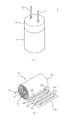
- FIG. 1 It is a perspective view (a) which shows typically the appearance of the 1st Embodiment of a power storage device, and is a perspective view (b) which shows typically an internal winding structure.
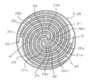
- sectional drawing which shows typically the cross-sectional structure of the winding structure of 1st Embodiment.
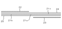
- explanatory drawing which shows typically the whole structure before winding of the winding structure of 1st Embodiment.
- enlarged cross-sectional view which shows typically the cross-sectional structure of each component part of the winding structure of 1st Embodiment.
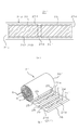
- It is an enlarged cross-sectional view which shows typically the connection structure of the tab member for connecting an external terminal in the 1st electrode body or the 2nd electrode body of 1st Embodiment.
- explanatory drawing (a)-(d) which shows typically the winding process for forming the winding structure of 1st Embodiment.
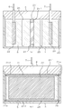
- explanatory cross-sectional view (a) schematically showing the radial cross-sectional structure of the accommodation structure in the container of the wound structure of the first embodiment
- explanatory cross-sectional view (b) schematically showing the circumferential cross-sectional structure.
- plan view (a) which shows typically the unfolded state of the intermediate electrode body of 2nd Embodiment
- perspective view (b) which shows typically a winding structure.
- an electric double layer capacitor will be described below as an example of an electric double layer capacitor as a power storage device.
- FIG. 1 the overall configuration of the first embodiment of the power storage device according to the present invention will be described.
- FIG. 1 is a schematic perspective view (a) of the power storage device 1 of the present embodiment and a perspective view (b) schematically showing a wound capacitor element 2 housed inside the power storage device 1.
- the power storage device 1 includes a winding type capacitor element 2 in which an electrolyte 5 is introduced (impregnated) into a winding structure 20 having a structure in which a band material (sheet material) is wound, and the winding type capacitor element.
- a container 3 having a bottomed shape (bottomed cylindrical shape) for accommodating 2 and a sealing body 4 of the container 3 are provided.
- the container 3 can be made of a metal such as aluminum.
- the sealing body 4 is provided with a through hole through which the first external terminal 6 and the second external terminal 7 provided in the winding type capacitor element 2 are inserted.
- the sealing body 4 has the first external terminal 6 and the second external terminal 7 led out to the outside while sealing the winding type capacitor element 2 housed in the container 3 through the through hole.
- the sealing body 4 can be made of various synthetic rubbers, elastomers, and the like.
- FIG. 2 is a schematic cross-sectional view schematically showing a cross section of the wound structure 20.
- the wound structure 20 has a band-shaped intermediate electrode body 21, and the intermediate electrode body 21 has a first extending portion 21b and a second extending portion 21b on both sides of the intermediate portion 21a in the extending direction. 21c and the like. Then, both the first extending portion 21b and the second extending portion 21c are wound around the intermediate portion 21a in a counterclockwise direction in the illustrated example.
- a strip-shaped first separator 24 and a second separator 25 are arranged on both the front and back surfaces of the intermediate electrode body 21 so as to cover the front and back surfaces of the intermediate electrode body 21, respectively.
- a band-shaped first electrode is formed in the gap between the first extending portion 21b on the inner peripheral side and the second extending portion 21c on the outer peripheral side.
- the body 22 is arranged.
- the first separator 24 is arranged between the first extending portion 21b and the first electrode body 22.
- the first separator 24 is also arranged between the second extending portion 21c and the first electrode body 22.
- a band-shaped second electrode body 23 is arranged between the second extending portion 21c on the inner peripheral side and the first extending portion 21b on the outer peripheral side.
- the second separator 25 is arranged between the second extending portion 21c and the second electrode body 23.
- the second separator 25 is also arranged between the first extending portion 21b and the second electrode body 23.
- Both the first separator 24 and the second separator 25 are integrally formed on the front and back surfaces of the intermediate electrode body 21. That is, both the first separator 24 and the second separator 25 are continuous at the portion adjacent to the intermediate portion 21a, and are connected to the portion along the first extending portion 21b and the second extending portion 21c. The part along the line is integrally formed. However, as in other embodiments described later, at least one of the first separator 24 and the second separator 25 is separated at a portion adjacent to the intermediate portion 21a, and the first extending portion is formed. The portion along the 21b and the portion along the second extending portion 21c may be formed separately.
- the intermediate electrode body 21, the first separator 24, the first electrode 22, the second separator 25, and the second electrode 23 are laminated on each other as shown in the illustrated example. It is wound in this manner, and is finally held and fixed in a wound state by a holding member (for example, a winding stop tape) 26 of the outermost layer.
- a holding member for example, a winding stop tape
- FIG. 2 is only a schematic diagram, and in a mode different from the actual winding state, for example, the reproducibility of the degree of adhesion between each layer is ignored, and in many cases, the number of windings is significantly reduced. Please note that it is shown.
- the outermost circular shape shown on the outside of the structure is the boundary of the accommodation space of the wound structure 20, which originally corresponds to the container 3 and the holding member 26, that is, the electrolyte 5 is present in the present embodiment. It shows the boundaries of possible spaces. That is, the circular shape in the figure defines a space having a housing function, a shape maintaining function, an insulating function, and the like, which are required depending on the situation of the wound structure 20 having the above structure. Shown schematically. Therefore, the shape (circular) itself has no meaning and is not limited.
- the pair of circles shown by the alternate long and short dash lines shown in FIG. 1 are the first electrode body 22 and the second electrode body 23 to be conductively connected to the first external terminal 6 and the second external terminal 7 shown in FIG.
- the holding member 26 does not have to be formed of one member, and may be divided into a plurality of parts. Further, the holding member 26 may be formed around the axis on the outer circumference of the wound structure 20 in a range of less than one circumference or in a range of one circumference or more. The point that it is not necessary to be formed by one member is the same for the other members constituting the wound structure 20.
- FIG. 3 schematically shows the arrangement of the intermediate electrode body 21, the first separator 24, the first electrode 22, the second separator 25, and the second electrode 23 in the expanded state.
- the first separator 24 is arranged between the intermediate electrode body 21 and the first electrode body 22.
- the second separator 25 is arranged between the intermediate electrode body 21 and the second electrode body 23.
- FIG. 4 is a cross-sectional view schematically showing a more detailed structure of each of the intermediate electrode body 21, the first separator 24, the first electrode 22, the second separator 25, and the second electrode 23.
- a current collector 211 made of a metal foil or the like and polar electrode layers 212 and 213 made of a carbon-containing porous material or the like are formed on both sides of the current collector 211.
- a current collector 221 made of a metal foil or the like and polar electrode layers 222,223 made of a carbon-containing porous material or the like are formed on both sides of the current collector 221.
- a current collector 231 made of a metal foil or the like and polar electrode layers 232 and 233 made of a carbon-containing porous material or the like are formed on both sides of the current collector 231.
- polar electrode layers 232 and 233 made of a carbon-containing porous material or the like are formed on both sides of the current collector 231.
- the current collectors 211, 221 and 231 for example, an aluminum foil having a thickness of 20 ⁇ m to 50 ⁇ m can be used.
- the polarization electrode layer 212,213,222,223,232,233 for example, activated carbon powder and carbon black are kneaded with a binder to prepare a carbon fine particle-containing paste, and the paste is 10 ⁇ m to 200 ⁇ m. It can be constructed by applying a thickness to both the front and back surfaces of the current collectors 211,221,231 and drying them.
- the polarizing electrode layer may be formed not on both sides of the current collectors 211, 221 and 231 but on only one of the current collectors 211, 221 and 231.
- a cellulose non-woven fabric having a thickness of 20 ⁇ m to 100 ⁇ m can be used.
- PI polyimide
- PEEK polyetheretherketone
- PET polyethylene terephthalate
- PTFE polytetrafluoroethylene
- PP polypropylene
- PE polyethylene
- the material constituting the separator is not limited to the above-mentioned various non-woven fabrics, and may be made of paper made only of cellulose pulp, for example.
- a resin adhesive tape such as polypropylene (PP), polyphenylene sulfide (PPS), or polyimide (PI), which has excellent solvent resistance, heat resistance, and insulation performance, is used. Can be done.
- PP polypropylene
- PPS polyphenylene sulfide
- PI polyimide
- electrolyte 5 introduced into the winding structure 20 various necessary electrolytes can be used depending on the type of power storage device.
- a tetraethylammonium salt can be used as a cation
- boron tetrafluoride, bistrifluoromethylsulfonylimide or the like can be used as an anion.
- a liquid or gel-like electrolyte can be used as the electrolyte at this time.
- the electrolytes include boric acid, adipic acid, maleic acid, benzoic acid, phthalic acid, salicylic acid, ammonia, triethylamine, tetramethylammonium hydroxide and the like.
- a solid electrolyte such as manganese dioxide or an organic semiconductor, or a conductive solid such as a conductive polymer or other (for example, a conductive inorganic material) can be used.
- non-fluid ion conductor between the intermediate electrode body and the first / second electrode body, it is possible to prevent contact / short circuit between the electrodes.
- the non-fluid ion conductor include a solid electrolyte mixed with a supporting substance such as a resin to form a sheet, a gel-like electrolyte, and the like.
- the non-fluid ion conductor here also has a function as a separator that prevents contact and short circuit between electrodes while ensuring ionic conductivity.
- FIG. 5 schematically shows an example of a conductive connection portion of the first electrode body 22 to the first external terminal 6 and a conductive connection portion of the second electrode body 23 to the second external terminal 7. show.
- FIG. 5 shows an example of the first electrode body 22 and the first external terminal 6, the second electrode body 23 and the second external terminal 7 can be configured in the same manner.
- at least one of the polarizing electrode layers 222 and 223 (222 in the illustrated example) is partially removed from the part of the first electrode body 22, and a part of the current collector 221 is removed.
- the exposed region 221a is formed.
- a tab member 214 conductively connected to the current collector 221 is joined to this region 221a.
- the position of the tab member 214 is set in advance together with the formation position of the region 221a so that the tab member 214 is arranged at a predetermined position in the situation where the winding structure 20 is formed.
- the protective film 215 having a property of preventing electrolytes and ions from passing through the gap between the first separator 24 facing the tab member 214 and the intermediate electrode body 21 and having an insulating property is provided. Can be placed.
- the protective film 215 can be attached on the surface of the first separator 24 on the side of the intermediate electrode body 21. In this way, the separator is less likely to deteriorate, and the characteristics of the power storage device are less likely to be deteriorated.
- the protective film 215 for example, polyphenylene sulfide (PPS) having a thickness of 1 ⁇ m to 200 ⁇ m, preferably 5 ⁇ m to 50 ⁇ m can be used.
- FIG. 6 is a schematic process diagram (a) to (d) schematically showing a process of forming the wound structure 20.
- the intermediate electrode body 21 is arranged on both the front and back surfaces of the intermediate electrode body 21 between the winding core members 10 (a pair of winding cores 10a and 10b) configured so as to be separable.
- the first separator 24 and the second separator 25 are arranged.
- the intermediate electrode body 21, the first separator 24, and the second separator 25 are formed by a left and right tape supply system (a supply mechanism including a supply reel with a rotation resistance imparting mechanism, a tension roller, a guide roller, etc.), which are not shown below. It is held so that it can be fed out by the same method).
- the intermediate portion 21a of the intermediate electrode body 21 and the intermediate portions of the first separator 24 and the second separator 25 are sandwiched between the pair of winding cores 10a and 10b, and FIG.
- the core material 10 As shown in 6 (c), the intermediate electrode body 21, the first separator 24, and the second separator 25 are formed into the core material 10 as shown in FIG. 6 (d). It can be wound around the intermediate portion 21a sandwiched between the two.
- the winding core material 10 is rotated so that the first electrode body 22 is caught in the first separator 24 and the second electrode body 23 is caught in the second separator 25.
- the left and right tape supply systems (not shown) are used for feeding.
- the holding member (winding tape) 26 is attached (attached) to the outermost layer to hold the wound state.
- each of the first external terminal 6 and the second external terminal 7 is conductively connected by joining to the corresponding tab member 214. It is inserted through the through hole of the sealing body 4. Then, the wound structure 20 is housed in the container 3 in a state of being impregnated with the electrolytic solution as, for example, the electrolyte 5, and finally, the opening of the container 3 is sealed with the sealing body 4.
- FIG. 7 is a schematic configuration sectional view (a) and (b) schematically showing the overall configuration of the power storage device 1 of the present embodiment formed as described above.
- FIG. 7 (a) schematically shows the relative positional relationship in the radial direction of the winding structure 20 (internal electrode structure) of the power storage device 1
- FIG. 7 (b) shows the winding of the power storage device 1.
- the relative positional relationship around the axis (circumferential direction) of the rotating structure 20 (internal electrode structure) is schematically shown.
- the intermediate electrode body 21 and the first electrode body 22 are interposed via the first separator 24.
- these two power storage function units are connected in series with each other between the first external terminal 6 and the second external terminal 7, compared with the case of a cell structure having only a single power storage function unit. It is possible to obtain a high voltage that is nearly double.
- the electric double layer capacitor generated at the interface between each electrode body 21, 22, 23 and the electrolyte 5 is used as a dielectric to store an electric double layer capacitor. The same applies to other capacitors.
- the first extending portion 21b and the second extending portion 21c on both sides of the intermediate portion 21a of the strip-shaped intermediate electrode body 21 are wound in the same direction.
- the first electrode body 22 is arranged via the first separator 24 in one of the pair of radial gaps between the first extending portion 21b and the second extending portion 21c.
- the second electrode body 23 is arranged in the other of the pair of radial gaps via the second separator 25. Then, by providing the first external terminal 6 conductively connected to the first electrode body 22 and the second external terminal 7 conductively connected to the second electrode body 23, the first external terminal 6 is provided.
- Two power storage function units are configured in series between the and the second external terminal 7 via an intermediate electrode body 21.
- the first storage function unit composed of the intermediate electrode body 21 and the first electrode body 22 and the second storage function unit composed of the intermediate electrode body 21 and the second electrode body 23 are Since the first storage function unit and the second storage function unit are arranged in the radial direction, one of them is arranged on the inside and the other is arranged on the outside because they are not configured to overlap inside and outside in the radial direction. There is no such relationship. That is, in the wound structure 20 of the present embodiment, the first electrode body 22 and the second electrode body 23 are arranged alternately or in parallel in an angular range around the intermediate portion 21a.
- the bias of the structural symmetry in the radial direction can be reduced.
- the first electrode body 22 and the second electrode body 23 are aligned with the first extending portion 21b and the second extending portion 21c, which are wound in the same direction on both sides of the intermediate portion 21a, respectively.
- the winding method is different, it is easy to manufacture and the number of parts is small because it can be manufactured by winding a laminated body of an electrode body and a separator by developing the conventional technique.
- the first extending portion 21b, the second extending portion 21c, and the first electrode body are centered on the intermediate portion 21a of the intermediate electrode body 21. It is preferable that the 22 and the second electrode body 23 are formed rotationally symmetrically.
- the first power storage function unit and the second power storage function unit have substantially the same structure, so that the intermediate electrode body 21, the first electrode body 22, and the second electrode It is possible to substantially ensure the electrical symmetry between the pair of power storage function units connected in series with the body 23. Then, with the above configuration, the bias of the applied voltage and the like can be reduced, so that the durability and characteristic stability of the power storage device can be improved.
- the characteristic difference becomes large due to the structural problem that the arrangement and dimensions in the radial direction are different among the plurality of power storage function units, so that the durability and the characteristic stability are improved. Problems are more likely to occur. For example, if the leakage current is significantly different between the storage function units, the voltage variation becomes large as the voltage application time elapses due to the influence of self-discharge. As a result, in the storage function unit with a small leakage current, the voltage increases with the passage of the voltage application time, and finally the voltage rises to the decomposition voltage of the solvent, and there is a risk that problems such as gas generation and resistance increase occur.
- the leakage current may increase due to a short circuit between the electrode bodies due to the electrolyte. This increase in leakage current also becomes a factor that further deteriorates the above-mentioned durability and characteristic stability.
- the power storage function unit composed of the intermediate electrode body 21 and the first electrode body 22, and the intermediate electrode body 21 and the second electrode body 23 are used. Since the second storage function unit to be configured is arranged in parallel on both sides of the intermediate portion 21a in a swirling manner, the first storage function unit and the second storage function unit are arranged in parallel. It becomes easier to make the characteristics of each functional unit uniform and balance.
- the intermediate electrode body 21, the first electrode body 22, and the second electrode body 23 are configured to be rotationally symmetric with respect to the intermediate portion 21a, so that the characteristics of both units can be balanced.
- first separator 24 and the second separator 25 are also configured to be rotationally symmetric with respect to each other.
- FIG. 7 shows only a schematic configuration. It is shown, and even if the outer peripheral portion is configured as shown in the figure, it is only an example. For example, unlike the illustrated configuration, a gap may be provided between the container 3 and the electrolyte 5, and the inner surface of the container 3 may be provided with an insulating coating. Further, since FIG. 7 is a schematic view, in a manner that does not match the cross-sectional structure shown in FIG. 2, a first separator is provided outside the first electrode body 22 and the second electrode body 23 in the radial direction.
- the 24 and the second separator 25 and the intermediate electrode body 21 are not arranged.
- the first separator 24 is arranged on the outer side in the radial direction of the first electrode body 22 so as to correspond to the cross-sectional structure shown in FIG. 2, and / or the second.
- the second separator 25 is arranged on the outer side in the radial direction of the electrode body 23, or the intermediate electrode is further on the outer side in the radial direction of each of the above-mentioned separators 24 and 25.
- the body 21 is configured to be arranged.
- the power storage device of the second embodiment according to the present invention will be described with reference to FIGS. 8 to 10.
- the configurations other than the winding type capacitor element 2' are the same as those in the first embodiment, and the overall configuration of the winding structure 20'shown in FIG. 8 and the winding structure 20 shown in FIG. 10 Since the schematic cross-sectional structure of ′ can be basically configured in the same manner as the wound structure 20, the same reference numerals are given to the portions that can be similarly configured, and the description thereof will be omitted.
- the side edge 21f which is the outer edge portion in the width direction, is the first electrode body 22 and the second. It is configured to project outward from the electrode body 23 of the winding structure 20'in the axial direction (see FIG. 9A).
- the side edge 21f is arranged at a position in the same axial direction as the outer edge positions of the first separator 24 and the second separator 25, or protrudes outward from the outer edge position in the axial direction. It is more preferable to be configured.
- the side edge 21f is different from the present embodiment and has the outer edge positions of the first separator 24 and the second separator 25 regardless of the relationship between the first electrode body 22 and the second electrode body 23. Leakage current between a pair of power storage function units can be improved by arranging them at the same axial position or protruding outward from the outer edge position in the axial direction. Has the effect of reducing.
- the end edge 21e which is the outer edge portion in the extending direction, is more of the wound structure 20'than the first electrode body 22 and the second electrode body 23. It is configured to be arranged on the outside in the radial direction (see FIG. 10).
- the edge 21e is arranged at a position in the same radial direction as the outer edge positions of the first separator 24 and the second separator 25, or is arranged outside the outer edge position in the radial direction. However, it is more preferable.
- the edge 21e is different from the present embodiment and has the outer edge positions of the first separator 24 and the second separator 25 regardless of the relationship between the first electrode body 22 and the second electrode body 23.
- the separability of the electrolyte can be improved, so that the effect of reducing the leakage current between the pair of power storage function units can be reduced. There is.
- the alternate long and short dash line shown in FIG. 8A shows the outer edges of the first electrode body 22 and the second electrode body 23.
- the outer edge also indicates a reference position indicating the relative positional relationship between the edge 21e and the side edge 21f in the outer edge portion 21d of the intermediate electrode body 21'in the wound structure 20'. These points will be described in more detail later.
- the outer edge portion 21d of the intermediate electrode body 21' is formed in a frame shape on the outside of the polarizable electrode layers 212 and 213 of the intermediate electrode body 21'. Further, both the edge 21e and the side edge 21f are formed on both sides in the extending direction and the width direction, respectively.
- the outer edge portion 21d is formed on the outside of the main body portion including the current collector 211 and the electrode region composed of the polarizing electrode layers 212 and 213.
- the outer edge portion 21d is not particularly limited, but is an electrolyte as compared with the main body portion (the laminated structure of the current collector 211 and the polarization electrode layers 212 and 213 described above) constituting the intermediate electrode body 21'. It is preferably composed of a portion that is difficult to retain 5 and / or its ions, or is difficult for the electrolyte 5 and / or its ions to pass through.
- the outer edge portion 21d is, for example, a portion where the electrolyte 5 and / or its ions are less likely to be retained, or an electrolyte than the (porous) polar electrode layers 212, 213 which easily retain the electrolyte 5 and / or its ions. It can be configured by extending a portion of 5 and / or a portion thereof that is difficult for ions to pass through. For example, it can be composed of a synthetic resin sheet, film, tape, etc., which will be described later. Further, the outer edge portion 21d may be formed of, for example, the current collector 211 which is exposed without forming or peeling off the polar electrode layers 212 and 213 which easily retain the electrolyte 5 and / or its ions.
- the outer edge portion 21d has, for example, the same structure as the laminated structure of the current collector 211 of the main body portion and the polarizing electrode portions 212 and 213, but is a core material as compared with the main body portion.
- the body 211 is thick, or the polarizable electrode layers 212, 213 are thin, and as a result, the electrolyte 5 and / or the ion is less likely to be retained than the main body portion, or the electrolyte 5 / or the ion is passed through. It may be a difficult part.
- These outer edge portions 21d are provided to reduce electrical leakage on the outer peripheral portion of the wound structure 20'. In the present embodiment, in particular, in order to enhance the separability between the side of the first electrode body 22 and the side of the second electrode body 23 with respect to the electrolyte 5 and its ions introduced into the wound structure 20'. It is provided in.
- the periphery of the intermediate electrode body 21' can be covered with the insulator, so that the first electrode body 22 and the second electrode body 22 and the second Internal continuity with the electrode body 23 can be suppressed, insulation performance can be improved, and leakage current can be reduced more effectively.
- the insulating edge portion 21d having different properties include polyphenylsulfide (PPS), polyimide (PI), aramid (total aromatic polyamide), polyetheretherketone (PEEK), polyethylene terephthalate (PET), and polytetra.
- Sheets, films, tapes and the like made of fluoroethylene (PTFE), polypropylene (PP), or polyethylene (PE) can be used. Since these materials have a property of not allowing the electrolyte 5 and ions to pass through in addition to the insulating property, the characteristics (insulation performance) of the power storage device such as reduction of leakage current can be further improved.
- PTFE fluoroethylene
- PP polypropylene
- PE polyethylene
- FIG. 9 is a diagram (a) schematically showing the relative positional relationship in the radial direction of the internal electrode structure of the power storage device 1 of the second embodiment in comparison with FIG. 7 showing the first embodiment, and FIG. It is a figure (b) which shows typically the relative positional relationship around the axis of the electrode structure of the power storage device.
- the side edge 21f of the outer edge portion 21d makes it easy for the electrolyte 5 to be divided in the radial direction of the wound structure 20', so that the deterioration of the insulation performance via the electrolyte 5 is suppressed. I understand.
- the side edge 21f is a holding member 26 arranged inside the container 3 or the inner surface of the sealing body 4 or the sealing resin (the boundary of the accommodation space of the wound structure 20'). That is, in the present embodiment, it is in contact with the boundary of the space where the electrolyte 5 can exist). In this way, when the side edge 21f abuts on the boundary outside the accommodation space of the wound structure 20'in the axial direction, the accommodation space is substantially divided in the radial direction of the wound structure 20'. Therefore, the insulation performance can be further improved.
- the side edge 21f is effective in dividing the electrolyte 5.
- the side edges 21f are provided on both sides in the width direction, but only one of them may be used. However, it goes without saying that it is more effective that the pair of side edges 21f on both sides in the width direction project together or both come into contact with the boundary (the inner surface or the like) as shown in the illustrated example.
- the end edge 21e of the outer edge portion 21d is the first electrode body 22 and the second electrode body 23, and the first separator 24 and the second separator in the wound structure 20'. It is arranged outside the winding structure 20'in the radial direction with respect to 25. As shown in FIG. 10, the outer peripheral arrangement of the edge 21e can further enhance the separability of the electrolyte 5 in the circumferential direction in the wound structure 20'.
- the holding member 26, or the sealing body 4 or the sealing resin in which the end edge 21e is arranged on the outer side (outer peripheral side) of the wound structure 20'in the radial direction of the container 3 or the inner side thereof.
- the edge 21e is provided on both sides of the intermediate electrode body 21'in the extending direction, but only one of them may be provided. However, as shown in the illustrated example, it is more effective that the pair of end edges 21e on both sides of the intermediate electrode body 21'in the extending direction are both arranged on the outer peripheral portion or both come into contact with the boundary (the inner surface or the like). It goes without saying that it is a target.
- the outer edge portion 21d of the intermediate electrode body 21' such as the side edge 21f shown in FIG. 9 and the edge portion 21e shown in FIG. Will be done.
- the edge shown by the alternate long and short dash line in FIG. 2 is on the outer peripheral portion in the radial direction. Leakage current is reduced and insulation performance is improved by arranging the outer edge portion of the intermediate electrode body 20 in such a manner that it is arranged or the side edge shown by the alternate long and short dash line in FIG. 7 projects in the axial direction. do.
- a portion having a material or structure having a high separating action of the electrolyte 5 such as the current collector 211 which is the core material of the intermediate electrode body 20 reaches the end surface of the outer edge portion 21d (end edge 21e or side edge 21f).
- the effect of reducing the leakage current can be more preferably obtained.
- the portion is configured to be relatively thicker than the surface layer portion such as the polar electrode layer, the separability to the electrolyte 5 is also enhanced, which is more effective.
- the side edge of the intermediate electrode body 20 is in contact with the outer boundary in the axial direction of the accommodation space, or the end edge is in contact with the outer boundary in the radial direction of the accommodation space. The same is true for the form.
- the side edge 21f which is the outer edge portion in the width direction, is the first electrode body 22 and the second electrode. It is arranged outside the body 23 and the first separator 24 and the second separator 25 in the axial direction.
- the side edge 21f protrudes outward in the axial direction of the wound structure 20'from at least one of the first electrode body 22 and the second electrode body 23, the space between the pair of storage function units It is considered to be effective in improving the insulation performance because it reduces the leakage current.
- the end edge 21e which is the outer edge portion in the extending direction, is the first electrode body 22 and the second electrode body 23. Is arranged outside the winding structure 20'in the radial direction. However, if the edge 21e is arranged outside at least one of the first electrode body 22 and the second electrode body 23 in the radial direction of the wound structure 20', a pair of power storage function units. It is considered that it is effective in improving the insulation performance because the separability between the two can be improved.
- edge 21e is arranged outside at least one of the first separator 24 and the second separator 25 in the radial direction of the wound structure 20', it is between the pair of power storage function units. It is considered that it is effective in improving the insulation performance because the separability can be improved.
- the boundary (the inner surface and the like). Is preferably insulating.
- the boundary is conductive, a plurality of different electrode bodies are in contact with the same member constituting the boundary, and the first electrode body 22 and the second storage function
- the electrolyte in the unit is in contact with the member forming the same boundary, or the second electrode body 23 and the electrolyte in the first power storage function unit are in the same member forming the boundary. It suffices to avoid both of being in contact with each other.
- the power storage device of the third embodiment according to the present invention will be described with reference to FIG.
- the configurations other than the first separator 24'and the second separator 25' can be configured in the same manner as in the first embodiment or the second embodiment. The description thereof will be omitted.
- the first separator 24' is provided with a missing portion 24a' adjacent to the vicinity of the intermediate portion 21a of the intermediate electrode body 21, so that the separator portion 24b along the first extending portion 21b is provided.
- ′ And a separator portion 24c ′ along the second extending portion 21c are formed separately.
- the second separator 25' is provided with a missing portion 25a'adjacent to the vicinity of the intermediate portion 21a of the intermediate electrode body 21, so that the second separator 25' has a separator portion 25b'along the first extending portion 21b. It is formed separately from the separator portion 25c'along the second extending portion 21c.
- the inner end portion of the first separator 24b'and the second separator 25' is arranged closer to the center side (the side of the intermediate portion 21a), the inner end side portion of the first separator 24b'and the second separator 25'is the first electrode body 22 and The insulation performance is ensured if it extends over an angle range beyond the inner end portion of the second electrode body 23. Further, with the same structure and material as the different characteristic edge portion 21d having the above-mentioned insulating performance, an insulator may be arranged at the inner ends of the first electrode body 22 and the second electrode body 23, or the insulator may be extended. You may form a part.
- the outer edge portion (side edge) of the intermediate electrode body 20 is projected to the outside in the axial direction of the wound structure 20, and / or the outer edge portion (end edge) is formed.
- the wound structure 20 By arranging the wound structure 20 on the outer side in the radial direction, the leakage current can be reduced and the insulation performance can be improved. In these cases, it is more desirable to bring the outer edge portion into contact with the outer boundary (the inner surface or the like) in the axial direction and / or the radial direction of the accommodation space of the wound structure 20.
- the configurations other than the intermediate electrode body 21, the first separator 24, and the second separator 25 can be configured in the same manner as in the first to third embodiments.
- the same reference numerals are given, and the description thereof will be omitted.
- the intermediate electrode body 21, the first separator 24, and the second separator 25 are provided with the adhesive layers 27 and 28 between the intermediate electrode body 21, the first separator 24, and the second separator 25.
- Separator 25 is integrally configured, and the integrated intermediate electrode body 21, the first separator 24, and the second separator 25 are wound together with the first electrode body 22 and the second electrode body 23 as described above.
- the adhesive layers 27 and 28 can be made of various adhesives or adhesives. In this way, the winding process is facilitated, and the winding mode of the winding structure can be formed in an orderly and reproducible manner.
- the intermediate electrode body 21, the first separator 24, and the second separator 25 are integrated, but for example, with the above configuration or instead of the above configuration, the first A configuration in which the separator 24 of 1 and the first electrode body 22 are integrated and / or a configuration in which the second separator 25 and the second electrode body 25 are integrated may be adopted.
- the outer edge portion (side edge) of the intermediate electrode body 20 is projected to the outside in the axial direction of the wound structure 20, and / or the outer edge portion (end edge) is formed.
- the wound structure 20 By arranging the wound structure 20 on the outer side in the radial direction, the leakage current can be reduced and the insulation performance can be improved. In these cases, it is more desirable to bring the outer edge portion into contact with the outer boundary (the inner surface or the like) in the axial direction and / or the radial direction of the accommodation space of the wound structure 20.
- the power storage device of the fifth embodiment according to the present invention will be described with reference to FIG.
- the configurations other than the intermediate electrode body 31 can be configured in the same manner as in the first to fourth embodiments. Therefore, the same reference numerals are given to the parts that can be configured in the same manner, and the description thereof will be omitted.
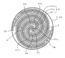
- the intermediate electrode body 31 of the present embodiment is composed of a plurality of electrode body layers 31h and 31i arranged in the thickness direction with the separator layer 31g interposed therebetween.
- the two electrode body layers 31h and 31i are arranged inside and outside via one separator layer 31g, but three or more electrode body layers may be arranged via the separator layer, respectively.
- the intermediate electrode body 31 is composed of a plurality of electrode bodies, it is possible to form one or more power storage function units (third power storage function units) only with the intermediate electrode body 31. , Further high voltage can be achieved.
- the separator layer 31g can be made of the same material as the first separator 24 and the second separator 25.
- the outer edge portion (side edge) of the intermediate electrode body 20 is projected to the outside in the axial direction of the wound structure 20, and / or the outer edge portion (end edge) is formed.
- the wound structure 20 By arranging the wound structure 20 on the outer side in the radial direction, the leakage current can be reduced and the insulation performance can be improved. In these cases, it is more desirable to bring the outer edge portion into contact with the outer boundary (the inner surface or the like) in the axial direction and / or the radial direction of the accommodation space of the wound structure 20.
- each of the plurality of electrode body layers 31h and 31i is extended to the outer periphery of the wound structure 30 via the separator layer 31g, and each of the separator layer 31g and the electrode body layers 31h and 31i is the boundary of the accommodation space ( It is desirable that each layer is formed in a stepped shape so as to come into contact with the inner surface and the like.
- the power storage device of the sixth embodiment according to the present invention will be described with reference to FIG.
- the configurations other than the intermediate electrode body 41 (intermediate portion 41a, first extending portion 41b, second extending portion 41c) can be configured in the same manner as in the first to fifth embodiments. Therefore, the same reference numerals are given to the parts that can be configured in the same manner, and the description thereof will be omitted.
- the outer periphery of the intermediate electrode body 41 is passed through the first electrode body 22 and the second electrode body 23 via the first separator 24 and the second separator 25, respectively.
- the structure is such that the portions 41j and 41k cover the outer peripheral side in the radial direction, respectively. That is, the outer peripheral portions 41j and 41k of the first extending portion 41b and the second extending portion 41c have a wider angle on the outer peripheral side than the outer peripheral portions of the first electrode body 22 and the second electrode body 23. It is formed over a range. In this way, the first electrode body 22 and the second electrode body 23 are surrounded by the intermediate electrode body 41 over the entire circumference (over the entire angle range) when viewed in the radial direction. As a result, it is possible to suppress electrical leakage beyond the intermediate electrode body 41 between the first electrode body 22 and the second electrode body 23, so that the insulation characteristics can be further improved.
- the outer peripheral portions 41j and 41k of the intermediate electrode body 41 come into contact with the boundary of the accommodation space (the inner surface and the like). Further, with or instead of the above configuration, in the range 41L, 41M surrounded by the illustrated two-dot chain line, the outer peripheral portions 41j, 41k (for example, the end portions thereof) of the intermediate electrode body 41 and the outer peripheral portion thereof.
- the outer peripheral portions 41j, 41k for example, the end portions thereof
- the outer peripheral portions of the first separator 24 and the second separator 25 are formed on the first electrode body 22 and the second electrode body. It is desirable to intervene between the intermediate electrode body 41 and the intermediate electrode body 41 over a wider angle range on the outer peripheral side than 23. In order to ensure the insulating property of the intermediate electrode body 41, the outer peripheral portions of the first separator 24 and the second separator 25 extend to the outer peripheral side in a wider angle range on the outer peripheral side of the intermediate electrode body 41. Insulation may be ensured by the boundary of the accommodation space (the inner surface or the like).
- the power storage device of the seventh embodiment according to the present invention will be described with reference to FIG.
- the intermediate electrode body 21 ′′ intermediate portion 21a, first extending portion 21b ′′, second extending portion 21c ′′
- the first electrode body 22 ′′ the first electrode body 22 ′′
- the second electrode body 23 the same reference numerals are given to the portions that can be similarly configured, and the description thereof will be omitted.
- FIG. 1 the present embodiment, FIG.
- the first extending portion 21b ′′ and the second extending portion 21c ′′ of the intermediate electrode body 21 ′′ have a first electrode in the outermost peripheral angular range of the outer peripheral portion of the wound structure. Since the polarization electrode layer is not formed on the outer peripheral surface that does not face the body 22 ′′ and the second electrode body 23 ′′, the outer peripheral exposed regions 21bs and 21cs are provided in which the current collector 211 is exposed. Further, in the first electrode body 22 ", the polarization electrode layer is not formed on the outer peripheral surface that does not face the intermediate electrode body 21" in the angle range of the outermost circumference in the outer peripheral portion of the wound structure. As a result, an outer peripheral exposed region 22s in which the current collector 221 is exposed is provided.
- the polarization electrode layer is not formed on the outer peripheral surface that does not face the intermediate electrode body 21" in the angle range of the outermost circumference in the outer peripheral portion of the wound structure.
- an outer peripheral exposed region 23s is provided in which the current collector 231 is exposed.
- the durability deteriorates due to the presence of the polarized electrode layer facing the electrode and the polarized electrode layer not facing the electrode on the front and back surfaces. It is possible to suppress variations in durability on the front and back surfaces. That is, in the present embodiment, the polarized electrode layer is not formed in the portions of the electrode bodies 21 ′′, 22 ′′, and 23 ′′ that do not face the other electrode bodies. , The problem due to the deterioration of durability can be avoided. However, the end portions of both electrode bodies are provided so that the intermediate electrode body 21 "and the first electrode body 22" and the second electrode body 23 "do not face each other on the outer peripheral portion of the wound structure.
- the outer peripheral ends of the first electrode body 22 ′′ and the second electrode body 23 ′′ may be aligned with the first extending portion 21b ′′ of the intermediate electrode body 21 ′′. If the angular positions of the outer peripheral ends of the extending portion 21c ′′ of 2 are aligned, it is not necessary to provide the outer peripheral exposed region on the first electrode body 22 ′′ and the second electrode body 23 ′′, and the first extending portion
- the outer peripheral exposed regions 21bs and 21cs may be formed only in the portion 21b "and the second extending portion 21c".
- the power storage device of the eighth embodiment according to the present invention will be described with reference to FIG.
- This embodiment is different from each of the above-described embodiments in that the partition members 56 and 57 are arranged in a part of the internal structure of the wound structure 50, but the other configurations are the above-mentioned embodiments and their description. Since it can be formed in the same manner as the configuration according to the above, the description of the fact that the same configuration can be adopted as long as there is no particular problem will be omitted.
- the intermediate electrode body 51 intermediate portion 51a, first extending portion
- Electrolyte 5 (not shown), first external electrode 6, second external electrode 7.
- the first separator 54 is arranged between the first electrode body 52 and the second extending portion 51c, similarly to the first separator 24 of each of the above-described embodiments. However, unlike the first separator 24 of each of the above-described embodiments, it is not arranged between the first electrode body 52 and the first extending portion 51b. Further, the second separator 55 is arranged between the second electrode body 53 and the first extending portion 51b in the same manner as the second separator 25 of each of the above-described embodiments. Unlike the second separator 25 of the embodiment, it is not arranged between the second electrode body 53 and the second extending portion 51c.
- the partition member 56 is arranged so as to be interposed between the first electrode body 52 and the first extending portion 51b, and the second electrode body 53 and the second electrode body 53. It is a point that the partition member 57 is arranged so as to intervene between the second extending portion 51c and the second extending portion 51c.
- These partition members 56 and 57 are one of both the inner and outer gaps in the radial direction between the intermediate electrode body 51 and the first electrode body 52 or the second electrode body 53 (in the illustrated example, any of them). By being arranged in the outer peripheral side gap in the radial direction), the facing region between the electrodes is provided only in the other gap between the intermediate electrode body 51 and the first electrode body 52 or the second electrode body 53.
- the partition members 56 and 57 act as an electrically insulating barrier. Therefore, as the partition members 56 and 57, the leakage current between the intermediate electrode body 51 and the first electrode body 52 or the second electrode body 53 in one of the above gaps is reduced as much as possible to improve the withstand voltage characteristic. It is composed of materials and shapes (structures) that can be secured. For this reason, the partition members 56 and 57 preferably have electrolyte blocking properties and electrical insulating properties. That is, the partition member 56.57 has a blocking property that an electrolyte (ion) cannot pass through, and also has an electrical insulating property itself.
- the partition member 56.57 is preferably made of a synthetic resin.
- Examples of the synthetic resin include polyphenylene sulfide (PPS), polyimide (PI), aramid (total aromatic polyamide), polyetheretherketone (PEEK), polyethylene terephthalate (PET), polytetrafluoroethylene (PTFE), polypropylene ( PP), polyethylene (PE) and the like can be mentioned.
- PPS polyphenylene sulfide
- PI polyimide
- PEEK polyetheretherketone
- PET polyethylene terephthalate
- PTFE polytetrafluoroethylene
- PE polypropylene
- PE polyethylene
- the partition members 56 and 57 are preferably in the form of a sheet as a preferable form for forming the winding structure 50. Further, when an electrolyte is introduced into the wound structure, it is preferable that the partition member does not allow the electrolyte and its ions to pass through. In particular, it is desirable that the electrolyte and its ions have impermeable and non-retaining properties. For example, it is composed of a sheet material having no voids. As a result, it becomes possible to further reliably reduce the leakage current through the electrolyte, and further improve the insulation performance of the device.
- Suitable synthetic resin sheet materials in these respects include polytetrafluoroethylene (PTFE), pafluoroalkoxyalkane (PFA), perfluoroethylene propene copolymer (FEP), polyfluorovinylidene (PVDF), and ethylene / tetrafluoro.
- Fluororesin sheets such as ethylene copolymer (ETFE) and polychlorotrifluoroethylene (PCTFE) can be mentioned.
- the partition members 56 and 57 have a surface having a property of repelling the electrolyte.
- the surface material at this time for example, the above-mentioned fluororesin sheet is preferable.
- a surface layer having a property of repelling an electrolyte may be formed on the surface by applying a coating or the like.
- the contact angle ⁇ with respect to the target electrolyte (liquid) is preferably 80 degrees or more, and particularly preferably an angle (obtuse angle) exceeding 90 degrees.
- the contact angle of the fluororesin is about 100 degrees.
- the partition members 56 and 57 are made of a sheet having electrical insulation without gaps as described above.
- the partition members 56 and 57 are made of synthetic resin sheets as described above, in order to make the partition members 56 and 57 as compact as possible while ensuring electrical insulation and impermeableness of electrolytes (ions), it is necessary to make the partition members 56 and 57 as compact as possible.
- the thickness is preferably in the range of 5 ⁇ m-1 mm, and particularly preferably in the range of 10 ⁇ m to 500 ⁇ m. In particular, it is more desirable to be in the range of 20 ⁇ m to 200 ⁇ m.
- the thickness is less than each of the above ranges, the electrolyte and its ions easily pass through, and if the thickness exceeds each of the above ranges, the winding property at the time of manufacturing is deteriorated, which is disadvantageous for making the power storage device compact.
- the intermediate electrode body 51, the first electrode body 52, and the second electrode body 53 are the current collectors 511 and 521, 531 and the polar electrode layer 512, 513. It can be configured by a laminated structure with 522,532.
- the partition member 56 is interposed between the first electrode body 52 and the first extending portion 51b, and the second electrode body 53 and the second extending portion 51b are interposed. Since the partition member 57 is interposed between the 51c and the 51c, as shown in FIG. 16B, the opposing regions of the intermediate electrode body 51, the first electrode body 52, and the second electrode body 53 that perform the storage function are formed.
- the polarizable electrode layers 521, 513, 522, 532 are laminated and formed only on the side of the facing region, and the polarizable electrode layers are not formed on the side of the partition members 56 and 57. ..
- the non-opposing region of the polar electrode layer can be reduced, so that deterioration of durability and variation in durability on the front and back surfaces due to the non-opposing region can be suppressed.
- the electrically insulating partition members 56 and 57 having an electrolyte blocking property in one of the two gaps between the intermediate electrode body 51 and the first electrode body 52 and the second electrode body 53.
- the partition members 56 and 57 are the same inside and outside in the radial direction in the gap between the intermediate electrode body 51 and the first electrode body 52 and the second electrode body 53.
- the positions of the outer edges (side edges) of the partition members 56 and 57 of the present embodiment are the positions of the intermediate electrode body 51 and the first electrode body 52 or the second electrode body 53 from the viewpoint of improving the insulating characteristics. It is preferable that the wound structure 50 projects outward in the axial direction rather than at least one of them (preferably both). In particular, the positions of both outer edges (both edges) of the partition members 56 and 57 in the axial direction are at least one of the intermediate electrode body 51 and the first electrode body 52 or the second electrode body 53 (preferably). It is desirable that the wound structure 50 protrudes outward in the axial direction rather than both).
- the winding structure 50 when the winding structure 50 is housed in a housing space composed of a housing made of a container 3 or a sealing body 4, a holding member 26 inside the housing, or the like, the outer edge portion (side edge) is stored in the storage space. It is desirable to abut (fix) the boundary on the outer side of the accommodation space in the axial direction.
- the positions of the outer edge portions (end edges) 56e and 57e of the partition members 56 and 57 are the intermediate electrode body 51 and the first electrode body 52 or the second electrode body 53 from the viewpoint of improving the insulating characteristics. It is preferable that the wound structure 50 projects outward in the radial direction rather than at least one of the above (preferably both). Further, as shown in the illustrated example, the outer edge portion (outer end edge) of the intermediate electrode body 51, the first electrode body 52, or the second electrode body 53 is the outer peripheral portion (end edge 56e, 57e) of the partition members 56, 57. It is preferable to have a structure that is covered from the outer peripheral side by a portion extending from the outer peripheral side.
- the outer edge portions (radial end edges) 56e and 57e are composed of a housing in which the winding structure 50 is composed of a container 3 and a sealing body 4, a holding member 26 inside the winding structure 50, and the like, as shown in the illustrated example.
- the winding structure 50 is composed of a container 3 and a sealing body 4, a holding member 26 inside the winding structure 50, and the like, as shown in the illustrated example.
- the positions of the inner edges (inner end edges) of the partition members 56 and 57 in the radial direction are also wound more than those of the first electrode body 52 or the second electrode body 53. It is preferable that the rotating structure 50 is arranged so as to extend to the inner peripheral side of the structure 50.
- the intermediate electrode body 51, the first electrode body 52 or the second electrode body 53 may have an inner edge portion (inner end edge) covered from the inner peripheral side by the inner edge portions of the partition members 56 and 57.
- the inner edges of the partition members 56 and 57 are in contact with each other (more preferably, connected and fixed) to the inner peripheral portions such as the intermediate portion 51a of the intermediate electrode body 51. It is desirable for further improvement of insulation characteristics.
- the inner edges of the partition members 56 and 57 may be in contact with (more preferably, fixedly connected) to the inner peripheral portions of the first separator 54 and the second separator 55, respectively.
- the inner edges of the partition members 56 and 57 may be separated from the intermediate electrode body 51 and the separators 54 and 55, as shown by the dotted lines in FIG. 16B.
- the outer peripheral portions of the intermediate electrode body 51, the first electrode body 52, and the second electrode body 53 are the outer peripheral portions of the partition members 56, 57 as shown in the illustrated example. It is preferable to have a structure that is covered from the outer peripheral side in the radial direction by a portion extending from the radial edge edges 56e and 57e).
- the outer peripheral portions of the first separator 54 and the second separator 55 are the intermediate electrode body 51, the first electrode body 52 and the second electrode body 53. It is desirable that it extends to the outer peripheral side rather than the outer peripheral portion.
- each electrode body (particularly the polarizable electrode layer) and each separator are formed between the regions partitioned by the partition members 56 and 57 so that the adhesive layer does not interfere with the electrical insulation. It is preferable that they are not connected via an adhesive layer.
- the power storage device of the ninth embodiment according to the present invention will be described with reference to FIG.
- the partition members 56'and 57' are arranged in a part of the internal structure of the wound structure 50', but the eighth embodiment is different from the eighth embodiment in the following points. different. That is, in the present embodiment, the partition member 56'is arranged between the first electrode body 52 and the second extending portion 51c, and between the second electrode body 53 and the first extending portion 51b.
- the partition member 57' is arranged in.
- the first separator 54' is arranged between the first electrode body 52 and the first extending portion 51b
- the second separator 54' is arranged between the second electrode body 53 and the second extending portion 51c.
- Separator 55' is arranged.
- the partition members 56'and 57' are inside any of a pair of radial inner and outer gaps between the intermediate electrode body 51 and the first electrode body 52 or the second electrode body 53. They are arranged in the gaps on the peripheral side.
- the wound structure 50'of the present embodiment can also have the same effect as that of the eighth embodiment.
- the first separator 54'and the second separator 55' are also interposed. The same is true for the eighth embodiment with respect to the configuration and the action effect when the polar electrode layer is formed in the mutually facing portions and the non-opposing portion of the polar electrode layer is not formed.
- the power storage device of the present invention is not limited to the above-mentioned illustrated examples, and it goes without saying that various modifications can be made without departing from the gist of the present invention.
- the internal electrode structure of the wound structure is electrolyzed by forming an insulating film such as an oxide film on the surface of each electrode body. It is obvious to those skilled in the art that it can be easily applied to capacitors.
- the internal electrode structure according to the present invention can be applied to various capacitor-type power storage devices such as various other capacitors.
- the internal electrode structure according to the present invention can also be applied to a chemical power storage device such as a battery.
- the configuration of each part of each of the above embodiments can be configured in any combination as long as there is no particular problem.
- an example of an inductive power storage device in which lead wires (first external terminal and second external terminal) are attached to internal electrodes (first electrode body and second electrode body) and wound up.
- the power storage device of the present invention is not limited to the induction type, but is not limited to the induction type, but is the axis of the internal electrode (first electrode body and second electrode body) of the winding structure. It is also possible to configure it as a non-inductive power storage device in which lead wires (first external terminal and second external terminal) are attached to the edge portion in the direction.
- the power storage function unit is composed of the intermediate electrode body 21 and the first electrode body 22, and the intermediate electrode body 21 and the second electrode body 23.
- Two power storage function units are configured in series via an intermediate electrode body 21, such as a second power storage function unit.
- an anisotropic ion conductor having a high ionic conductivity in the thickness direction and a low ionic conductivity in the plane direction as the electrolyte 5
- a short circuit occurs between the power storage function units via the electrolyte 5. Since it is possible to reduce problems due to the common electrolyte effect such as self-discharging current through the path, it is possible to further reduce the electrical leakage of the above embodiment.
- Anisotropic ionic conductors require that the electrical conductivity in the direction along the surface of each electrode body is smaller than the electrical conductivity in the direction perpendicular to the surface of each electrode body, and in particular, along the surface of each electrode body. It is preferable to use an anisotropic ionic conductor whose electrical conductivity in the direction is 10% or less of the electrical conductivity in the direction perpendicular to the surface of each electrode body.
Landscapes
- Engineering & Computer Science (AREA)
- Power Engineering (AREA)
- Microelectronics & Electronic Packaging (AREA)
- Chemical & Material Sciences (AREA)
- Chemical Kinetics & Catalysis (AREA)
- Electrochemistry (AREA)
- General Chemical & Material Sciences (AREA)
- Manufacturing & Machinery (AREA)
- Electric Double-Layer Capacitors Or The Like (AREA)
- Secondary Cells (AREA)
Priority Applications (3)
| Application Number | Priority Date | Filing Date | Title |
|---|---|---|---|
| CN202180021107.2A CN115335938A (zh) | 2020-04-20 | 2021-04-13 | 蓄电设备 |
| JP2022516976A JP7768879B2 (ja) | 2020-04-20 | 2021-04-13 | 蓄電デバイス |
| US17/996,531 US12463298B2 (en) | 2020-04-20 | 2021-04-13 | Electrical storage device |
Applications Claiming Priority (4)
| Application Number | Priority Date | Filing Date | Title |
|---|---|---|---|
| JP2020074722 | 2020-04-20 | ||
| JP2020-074722 | 2020-04-20 | ||
| JP2020166146 | 2020-09-30 | ||
| JP2020-166146 | 2020-09-30 |
Publications (1)
| Publication Number | Publication Date |
|---|---|
| WO2021215304A1 true WO2021215304A1 (ja) | 2021-10-28 |
Family
ID=78269391
Family Applications (1)
| Application Number | Title | Priority Date | Filing Date |
|---|---|---|---|
| PCT/JP2021/015323 Ceased WO2021215304A1 (ja) | 2020-04-20 | 2021-04-13 | 蓄電デバイス |
Country Status (4)
| Country | Link |
|---|---|
| US (1) | US12463298B2 (https=) |
| JP (1) | JP7768879B2 (https=) |
| CN (1) | CN115335938A (https=) |
| WO (1) | WO2021215304A1 (https=) |
Families Citing this family (2)
| Publication number | Priority date | Publication date | Assignee | Title |
|---|---|---|---|---|
| US20220336896A1 (en) * | 2021-04-19 | 2022-10-20 | Apple Inc. | Battery configurations with corrosion barrier |
| JPWO2023127826A1 (https=) * | 2021-12-27 | 2023-07-06 |
Citations (4)
| Publication number | Priority date | Publication date | Assignee | Title |
|---|---|---|---|---|
| JPS59101433U (ja) * | 1982-12-24 | 1984-07-09 | 日本電気株式会社 | 電気二重層コンデンサ |
| JP2006278266A (ja) * | 2005-03-30 | 2006-10-12 | Sanyo Electric Co Ltd | 扁平巻回電極体を備えた電池及びその製造方法 |
| JP2013149390A (ja) * | 2012-01-17 | 2013-08-01 | Toyota Industries Corp | 蓄電装置、蓄電装置が搭載された車両及び蓄電装置の製造方法 |
| JP2014013646A (ja) * | 2010-10-20 | 2014-01-23 | Sanyo Electric Co Ltd | 非水電解質二次電池 |
Family Cites Families (7)
| Publication number | Priority date | Publication date | Assignee | Title |
|---|---|---|---|---|
| KR100552431B1 (ko) * | 2005-03-31 | 2006-02-20 | 코칩 주식회사 | 고전압 전기이중층 커패시터 |
| JP4587996B2 (ja) * | 2005-11-22 | 2010-11-24 | 佐賀三洋工業株式会社 | 電解コンデンサ |
| WO2008130042A2 (en) | 2007-04-12 | 2008-10-30 | Linxross, Inc. | Bipolar supercapacitors and methods for making same |
| TW201015595A (en) * | 2008-09-22 | 2010-04-16 | Sanyo Electric Co | Winding-type electrolytic capacitor and method of manufacturing the same |
| JP5159598B2 (ja) * | 2008-12-26 | 2013-03-06 | 三洋電機株式会社 | 電解コンデンサ |
| JP6414731B2 (ja) * | 2013-10-01 | 2018-10-31 | 株式会社Gsユアサ | 蓄電素子及び蓄電装置 |
| JP6487712B2 (ja) * | 2015-02-23 | 2019-03-20 | 昭和電工パッケージング株式会社 | 蓄電デバイス |
-
2021
- 2021-04-13 WO PCT/JP2021/015323 patent/WO2021215304A1/ja not_active Ceased
- 2021-04-13 CN CN202180021107.2A patent/CN115335938A/zh active Pending
- 2021-04-13 JP JP2022516976A patent/JP7768879B2/ja active Active
- 2021-04-13 US US17/996,531 patent/US12463298B2/en active Active
Patent Citations (4)
| Publication number | Priority date | Publication date | Assignee | Title |
|---|---|---|---|---|
| JPS59101433U (ja) * | 1982-12-24 | 1984-07-09 | 日本電気株式会社 | 電気二重層コンデンサ |
| JP2006278266A (ja) * | 2005-03-30 | 2006-10-12 | Sanyo Electric Co Ltd | 扁平巻回電極体を備えた電池及びその製造方法 |
| JP2014013646A (ja) * | 2010-10-20 | 2014-01-23 | Sanyo Electric Co Ltd | 非水電解質二次電池 |
| JP2013149390A (ja) * | 2012-01-17 | 2013-08-01 | Toyota Industries Corp | 蓄電装置、蓄電装置が搭載された車両及び蓄電装置の製造方法 |
Also Published As
| Publication number | Publication date |
|---|---|
| US20230207978A1 (en) | 2023-06-29 |
| US12463298B2 (en) | 2025-11-04 |
| CN115335938A (zh) | 2022-11-11 |
| JP7768879B2 (ja) | 2025-11-12 |
| JPWO2021215304A1 (https=) | 2021-10-28 |
Similar Documents
| Publication | Publication Date | Title |
|---|---|---|
| US8815434B2 (en) | Electrode assembly for secondary battery with wound and folded separator portions and secondary battery having the same | |
| JP6618677B2 (ja) | 電極組み立て体及びこれを備える二次電池 | |
| US8748022B2 (en) | Pouch type battery | |
| US9190633B2 (en) | Pouch type lithium secondary battery | |
| US8034481B2 (en) | Pouch-type secondary battery | |
| JP6811003B2 (ja) | 電気化学セル及び電気化学セルの製造方法 | |
| US20160365544A1 (en) | Secondary battery | |
| EP2849247B1 (en) | Rechargeable battery | |
| JP6432952B1 (ja) | 電気化学セル | |
| JP6273665B2 (ja) | 電気化学デバイス | |
| US9401499B2 (en) | Electrode assembly and secondary battery having the same | |
| JP2016100270A (ja) | 蓄電素子 | |
| US10177351B2 (en) | Rechargeable battery | |
| WO2021215304A1 (ja) | 蓄電デバイス | |
| WO2017204137A1 (ja) | 蓄電素子、蓄電素子を備える蓄電装置、蓄電素子を備える移動体、及び蓄電素子を備える蓄電システム | |
| US20030215709A1 (en) | Power storage device and a portable apparatus | |
| KR20160095740A (ko) | 관통홈을 포함하는 전지셀 | |
| WO2017115859A1 (ja) | 蓄電素子 | |
| US11495832B2 (en) | Electrochemical cell | |
| JP7208871B2 (ja) | コンデンサ、コンデンサの製造装置およびコンデンサの製造方法 | |
| JP7691431B2 (ja) | 蓄電デバイス | |
| WO2017115857A1 (ja) | 蓄電素子 | |
| US12586846B2 (en) | Secondary battery | |
| WO2017208509A1 (ja) | 蓄電デバイス及びその製造方法 | |
| JP7119837B2 (ja) | 蓄電素子 |
Legal Events
| Date | Code | Title | Description |
|---|---|---|---|
| 121 | Ep: the epo has been informed by wipo that ep was designated in this application |
Ref document number: 21791614 Country of ref document: EP Kind code of ref document: A1 |
|
| ENP | Entry into the national phase |
Ref document number: 2022516976 Country of ref document: JP Kind code of ref document: A |
|
| NENP | Non-entry into the national phase |
Ref country code: DE |
|
| 122 | Ep: pct application non-entry in european phase |
Ref document number: 21791614 Country of ref document: EP Kind code of ref document: A1 |
|
| WWG | Wipo information: grant in national office |
Ref document number: 17996531 Country of ref document: US |