WO2021214824A1 - Rotor, motor, compressor, air conditioning device, and rotor manufacturing method - Google Patents
Rotor, motor, compressor, air conditioning device, and rotor manufacturing method Download PDFInfo
- Publication number
- WO2021214824A1 WO2021214824A1 PCT/JP2020/017035 JP2020017035W WO2021214824A1 WO 2021214824 A1 WO2021214824 A1 WO 2021214824A1 JP 2020017035 W JP2020017035 W JP 2020017035W WO 2021214824 A1 WO2021214824 A1 WO 2021214824A1
- Authority
- WO
- WIPO (PCT)
- Prior art keywords
- insertion hole
- magnet
- magnet insertion
- permanent magnet
- rotor
- Prior art date
Links
Images


Classifications
-
- H—ELECTRICITY
- H02—GENERATION; CONVERSION OR DISTRIBUTION OF ELECTRIC POWER
- H02K—DYNAMO-ELECTRIC MACHINES
- H02K1/00—Details of the magnetic circuit
- H02K1/06—Details of the magnetic circuit characterised by the shape, form or construction
- H02K1/22—Rotating parts of the magnetic circuit
- H02K1/27—Rotor cores with permanent magnets
- H02K1/2706—Inner rotors
- H02K1/272—Inner rotors the magnetisation axis of the magnets being perpendicular to the rotor axis
- H02K1/274—Inner rotors the magnetisation axis of the magnets being perpendicular to the rotor axis the rotor consisting of two or more circumferentially positioned magnets
- H02K1/2753—Inner rotors the magnetisation axis of the magnets being perpendicular to the rotor axis the rotor consisting of two or more circumferentially positioned magnets the rotor consisting of magnets or groups of magnets arranged with alternating polarity
- H02K1/276—Magnets embedded in the magnetic core, e.g. interior permanent magnets [IPM]
-
- F—MECHANICAL ENGINEERING; LIGHTING; HEATING; WEAPONS; BLASTING
- F25—REFRIGERATION OR COOLING; COMBINED HEATING AND REFRIGERATION SYSTEMS; HEAT PUMP SYSTEMS; MANUFACTURE OR STORAGE OF ICE; LIQUEFACTION SOLIDIFICATION OF GASES
- F25B—REFRIGERATION MACHINES, PLANTS OR SYSTEMS; COMBINED HEATING AND REFRIGERATION SYSTEMS; HEAT PUMP SYSTEMS
- F25B1/00—Compression machines, plants or systems with non-reversible cycle
- F25B1/04—Compression machines, plants or systems with non-reversible cycle with compressor of rotary type
-
- F—MECHANICAL ENGINEERING; LIGHTING; HEATING; WEAPONS; BLASTING
- F25—REFRIGERATION OR COOLING; COMBINED HEATING AND REFRIGERATION SYSTEMS; HEAT PUMP SYSTEMS; MANUFACTURE OR STORAGE OF ICE; LIQUEFACTION SOLIDIFICATION OF GASES
- F25B—REFRIGERATION MACHINES, PLANTS OR SYSTEMS; COMBINED HEATING AND REFRIGERATION SYSTEMS; HEAT PUMP SYSTEMS
- F25B31/00—Compressor arrangements
- F25B31/02—Compressor arrangements of motor-compressor units
- F25B31/026—Compressor arrangements of motor-compressor units with compressor of rotary type
-
- H—ELECTRICITY
- H02—GENERATION; CONVERSION OR DISTRIBUTION OF ELECTRIC POWER
- H02K—DYNAMO-ELECTRIC MACHINES
- H02K1/00—Details of the magnetic circuit
- H02K1/06—Details of the magnetic circuit characterised by the shape, form or construction
- H02K1/22—Rotating parts of the magnetic circuit
- H02K1/27—Rotor cores with permanent magnets
- H02K1/2706—Inner rotors
- H02K1/272—Inner rotors the magnetisation axis of the magnets being perpendicular to the rotor axis
- H02K1/274—Inner rotors the magnetisation axis of the magnets being perpendicular to the rotor axis the rotor consisting of two or more circumferentially positioned magnets
- H02K1/2753—Inner rotors the magnetisation axis of the magnets being perpendicular to the rotor axis the rotor consisting of two or more circumferentially positioned magnets the rotor consisting of magnets or groups of magnets arranged with alternating polarity
- H02K1/276—Magnets embedded in the magnetic core, e.g. interior permanent magnets [IPM]
- H02K1/2766—Magnets embedded in the magnetic core, e.g. interior permanent magnets [IPM] having a flux concentration effect
-
- H—ELECTRICITY
- H02—GENERATION; CONVERSION OR DISTRIBUTION OF ELECTRIC POWER
- H02K—DYNAMO-ELECTRIC MACHINES
- H02K15/00—Methods or apparatus specially adapted for manufacturing, assembling, maintaining or repairing of dynamo-electric machines
- H02K15/02—Methods or apparatus specially adapted for manufacturing, assembling, maintaining or repairing of dynamo-electric machines of stator or rotor bodies
- H02K15/03—Methods or apparatus specially adapted for manufacturing, assembling, maintaining or repairing of dynamo-electric machines of stator or rotor bodies having permanent magnets
-
- H—ELECTRICITY
- H02—GENERATION; CONVERSION OR DISTRIBUTION OF ELECTRIC POWER
- H02K—DYNAMO-ELECTRIC MACHINES
- H02K21/00—Synchronous motors having permanent magnets; Synchronous generators having permanent magnets
- H02K21/12—Synchronous motors having permanent magnets; Synchronous generators having permanent magnets with stationary armatures and rotating magnets
- H02K21/14—Synchronous motors having permanent magnets; Synchronous generators having permanent magnets with stationary armatures and rotating magnets with magnets rotating within the armatures
- H02K21/16—Synchronous motors having permanent magnets; Synchronous generators having permanent magnets with stationary armatures and rotating magnets with magnets rotating within the armatures having annular armature cores with salient poles
Landscapes
- Engineering & Computer Science (AREA)
- Power Engineering (AREA)
- Physics & Mathematics (AREA)
- Mechanical Engineering (AREA)
- Thermal Sciences (AREA)
- General Engineering & Computer Science (AREA)
- Manufacturing & Machinery (AREA)
- Permanent Field Magnets Of Synchronous Machinery (AREA)
- Iron Core Of Rotating Electric Machines (AREA)
Abstract
This rotor has: a rotor core having a magnet insertion hole and being annular about the axial line; and a plate-shaped permanent magnet disposed in the magnet insertion hole and having a thickness and a width in a plane orthogonal to the axial line. A width direction is specified by the width of the permanent magnet, and a thickness direction is specified by the thickness of the permanent magnet. The magnet insertion hole has a portion tilted with respect to the width direction so that an opening dimension T1 in the thickness direction at one end in the width direction becomes smaller than an opening dimension T2 in the thickness direction at a position apart from the one end by the width of the permanent magnet.
Description
本開示は、ロータ、モータ、圧縮機、空気調和装置およびロータの製造方法に関する。
This disclosure relates to a rotor, a motor, a compressor, an air conditioner, and a method for manufacturing a rotor.
永久磁石埋込型のロータでは、ロータコアに形成された磁石挿入孔内に永久磁石が配置されている。磁石挿入孔には、永久磁石の位置を規制する突起が設けられている(例えば、特許文献1参照)。
In the permanent magnet embedded type rotor, the permanent magnet is arranged in the magnet insertion hole formed in the rotor core. The magnet insertion hole is provided with a protrusion that regulates the position of the permanent magnet (see, for example, Patent Document 1).
一方、モータの負荷が大きい場合など、ステータコイルに大きな電流が流れた場合には、ステータからの磁束によって永久磁石の減磁が生じる場合がある。磁石挿入孔に突起を設けると、ステータからの磁束が突起を経由して永久磁石に流れやすくなり、永久磁石の減磁が生じ易くなる。
On the other hand, when a large current flows through the stator coil, such as when the load on the motor is large, the magnetic flux from the stator may cause demagnetization of the permanent magnet. If a protrusion is provided in the magnet insertion hole, the magnetic flux from the stator easily flows to the permanent magnet via the protrusion, and demagnetization of the permanent magnet is likely to occur.
本開示は、上記の課題を解決するためになされたものであり、永久磁石の減磁を抑制することを目的とする。
The present disclosure has been made to solve the above problems, and an object of the present disclosure is to suppress demagnetization of a permanent magnet.
本開示のロータは、磁石挿入孔を有し、軸線を中心とする環状のロータコアと、磁石挿入孔に配置され、軸線に直交する面において厚さおよび幅を有する平板状の永久磁石とを有する。永久磁石の幅によって幅方向が規定され、永久磁石の厚さによって厚さ方向が規定される。磁石挿入孔は、幅方向の一端における厚さ方向の開口寸法T1が、一端から永久磁石の幅だけ離間した位置における厚さ方向の開口寸法T2よりも小さくなるように、幅方向に対して傾斜した部分を有する。
The rotor of the present disclosure has an annular rotor core centered on an axis having a magnet insertion hole, and a flat plate-shaped permanent magnet arranged in the magnet insertion hole and having a thickness and width in a plane orthogonal to the axis. .. The width direction is defined by the width of the permanent magnet, and the thickness direction is defined by the thickness of the permanent magnet. The magnet insertion hole is inclined with respect to the width direction so that the opening dimension T1 in the thickness direction at one end in the width direction is smaller than the opening dimension T2 in the thickness direction at a position separated from one end by the width of the permanent magnet. Has a part that has been removed.
本開示によれば、磁石挿入孔の開口寸法T1の部分で永久磁石が保持されるため、磁石挿入孔内に永久磁石を位置決めするための突起を形成する必要がない。そのため、ステータからの磁束が突起に流れることによる永久磁石の減磁を抑制することができる。
According to the present disclosure, since the permanent magnet is held at the portion of the opening dimension T1 of the magnet insertion hole, it is not necessary to form a protrusion for positioning the permanent magnet in the magnet insertion hole. Therefore, it is possible to suppress demagnetization of the permanent magnet due to the magnetic flux from the stator flowing through the protrusions.
実施の形態1.
<モータの構成>
まず、実施の形態1のモータ100について説明する。図1は、実施の形態1のモータ100を示す横断面図である。モータ100は、ロータ1に永久磁石20が埋め込まれた永久磁石埋込型モータであり、例えば圧縮機300(図24)に用いられる。Embodiment 1.
<Motor configuration>
First, themotor 100 of the first embodiment will be described. FIG. 1 is a cross-sectional view showing the motor 100 of the first embodiment. The motor 100 is a permanent magnet embedded motor in which a permanent magnet 20 is embedded in a rotor 1, and is used, for example, in a compressor 300 (FIG. 24).
<モータの構成>
まず、実施の形態1のモータ100について説明する。図1は、実施の形態1のモータ100を示す横断面図である。モータ100は、ロータ1に永久磁石20が埋め込まれた永久磁石埋込型モータであり、例えば圧縮機300(図24)に用いられる。
<Motor configuration>
First, the
モータ100は、回転可能なロータ1と、ロータ1を囲むステータ5とを有する。ステータ5とロータ1との間には、例えば0.3~1.0mmのエアギャップが形成されている。ステータ5は、圧縮機300の一部である円筒状のシェル6に固定されている。
The motor 100 has a rotatable rotor 1 and a stator 5 that surrounds the rotor 1. An air gap of, for example, 0.3 to 1.0 mm is formed between the stator 5 and the rotor 1. The stator 5 is fixed to a cylindrical shell 6 that is part of the compressor 300.
以下では、ロータ1の回転軸である軸線C1の方向を、「軸方向」と称する。軸線C1を中心とする周方向を、「周方向」と称する。軸線C1を中心とする半径方向を、「径方向」と称する。ロータ1の回転方向は、図1における反時計回りとし、図1等に矢印R1で示す。
Hereinafter, the direction of the axis C1 which is the rotation axis of the rotor 1 is referred to as "axial direction". The circumferential direction centered on the axis C1 is referred to as "circumferential direction". The radial direction centered on the axis C1 is referred to as a "diameter direction". The rotation direction of the rotor 1 is counterclockwise in FIG. 1, and is indicated by an arrow R1 in FIG. 1 and the like.
<ステータの構成>
ステータ5は、ステータコア50と、ステータコア50に巻き付けられたコイル55とを有する。ステータコア50は、鋼板を軸方向に積層し、カシメ等により固定したものである。鋼板は、例えば電磁鋼板である。鋼板の板厚は、例えば0.1~0.7mmであり、ここでは0.35mmである。 <Constituent configuration>
Thestator 5 has a stator core 50 and a coil 55 wound around the stator core 50. The stator core 50 is formed by laminating steel plates in the axial direction and fixing them by caulking or the like. The steel plate is, for example, an electromagnetic steel plate. The plate thickness of the steel plate is, for example, 0.1 to 0.7 mm, and here 0.35 mm.
ステータ5は、ステータコア50と、ステータコア50に巻き付けられたコイル55とを有する。ステータコア50は、鋼板を軸方向に積層し、カシメ等により固定したものである。鋼板は、例えば電磁鋼板である。鋼板の板厚は、例えば0.1~0.7mmであり、ここでは0.35mmである。 <Constituent configuration>
The
ステータコア50は、軸線C1を中心とする環状のヨーク51と、ヨーク51から径方向内側に延在する複数のティース52とを有する。ヨーク51の外周は、シェル6の内側に固定されている。
The stator core 50 has an annular yoke 51 centered on the axis C1 and a plurality of teeth 52 extending radially inward from the yoke 51. The outer circumference of the yoke 51 is fixed to the inside of the shell 6.
ティース52は、周方向に一定間隔で形成されている。ティース52の数は、ここでは9であるが、3以上であればよい。隣り合うティース52の間には、コイル55を収容するスロットが形成される。ステータコア50のティース52には、絶縁部54を介して、コイル55が巻き付けられている。コイル55は、銅またはアルミニウム等の材料で構成されている。
Teeth 52 are formed at regular intervals in the circumferential direction. The number of teeth 52 is 9 here, but it may be 3 or more. A slot for accommodating the coil 55 is formed between the adjacent teeth 52. A coil 55 is wound around the teeth 52 of the stator core 50 via an insulating portion 54. The coil 55 is made of a material such as copper or aluminum.
ステータコア50は、ティース52毎に分割された複数の分割コア50Aを有する。分割コア50Aの数は、例えば9である。これらの分割コア50Aは、ヨーク51に形成された分割面58で接合され、周方向に連結されている。なお、ステータコア50は、複数の分割コア50Aを連結した構成に限定されるものではない。
The stator core 50 has a plurality of divided cores 50A divided for each tooth 52. The number of split cores 50A is, for example, 9. These split cores 50A are joined by a split surface 58 formed on the yoke 51 and are connected in the circumferential direction. The stator core 50 is not limited to a configuration in which a plurality of divided cores 50A are connected.
絶縁部54は、ステータコア50とコイル55との間に設けられる。絶縁部54は、例えば、ステータコア50の軸方向端部に配置されたインシュレータと、スロットの内面に配置された絶縁フィルムとで構成される。
The insulating portion 54 is provided between the stator core 50 and the coil 55. The insulating portion 54 is composed of, for example, an insulator arranged at the axial end of the stator core 50 and an insulating film arranged on the inner surface of the slot.
コイル55は、例えばマグネットワイヤで構成され、絶縁部54を介してティース52に巻き付けられている。コイル55の線径は、例えば0.8mmである。コイル55は、各ティース52に、集中巻により例えば70ターン巻かれている。なお、コイル55の線径およびターン数は、要求される回転数、トルク、印加電圧あるいはスロットの断面積に応じて決定される。
The coil 55 is composed of, for example, a magnet wire, and is wound around the teeth 52 via an insulating portion 54. The wire diameter of the coil 55 is, for example, 0.8 mm. The coil 55 is wound around each tooth 52 by a concentrated winding, for example, for 70 turns. The wire diameter and the number of turns of the coil 55 are determined according to the required rotation speed, torque, applied voltage, or cross-sectional area of the slot.
ヨーク51には、カシメ部56,57が形成されている。カシメ部56,57は、ステータコア50を構成する複数の鋼板を軸方向に固定するものである。カシメ部56は、ティース52の周方向中心を通る径方向の直線上に形成され、カシメ部57は、当該直線を挟んで周方向に対称な2箇所に形成されている。但し、カシメ部56,57の数および配置は、適宜変更することができる。
Caulking portions 56 and 57 are formed on the yoke 51. The caulking portions 56 and 57 are for fixing a plurality of steel plates constituting the stator core 50 in the axial direction. The caulking portion 56 is formed on a linear line in the radial direction passing through the circumferential center of the teeth 52, and the caulking portion 57 is formed at two positions symmetrical in the circumferential direction with the straight line interposed therebetween. However, the number and arrangement of the crimped portions 56 and 57 can be changed as appropriate.
ヨーク51の外周には、凹部59が形成されている。凹部59とシェル6との間には、圧縮機300における冷媒の通路が形成される。
A recess 59 is formed on the outer circumference of the yoke 51. A passage for the refrigerant in the compressor 300 is formed between the recess 59 and the shell 6.
<ロータの構成>
図2は、ロータ1を示す断面図である。ロータ1は、軸線C1を中心とする環状のロータコア10と、ロータコア10に取り付けられた永久磁石20と、ロータコア10の内周10bに固定されたシャフト25とを有する。シャフト25の中心軸線は、上述した軸線C1である。 <Rotor configuration>
FIG. 2 is a cross-sectional view showing therotor 1. The rotor 1 has an annular rotor core 10 centered on the axis C1, a permanent magnet 20 attached to the rotor core 10, and a shaft 25 fixed to the inner circumference 10b of the rotor core 10. The central axis of the shaft 25 is the axis C1 described above.
図2は、ロータ1を示す断面図である。ロータ1は、軸線C1を中心とする環状のロータコア10と、ロータコア10に取り付けられた永久磁石20と、ロータコア10の内周10bに固定されたシャフト25とを有する。シャフト25の中心軸線は、上述した軸線C1である。 <Rotor configuration>
FIG. 2 is a cross-sectional view showing the
ロータコア10は、鋼板を軸方向に積層し、カシメ等で一体化したものである。鋼板は、例えば電磁鋼板である。鋼板の板厚は、例えば0.1~0.7mmであり、ここでは0.35mmである。ロータコア10の内周10bには、シャフト25が焼嵌または圧入によって固定されている。
The rotor core 10 is made by laminating steel plates in the axial direction and integrating them by caulking or the like. The steel plate is, for example, an electromagnetic steel plate. The plate thickness of the steel plate is, for example, 0.1 to 0.7 mm, and here 0.35 mm. A shaft 25 is fixed to the inner circumference 10b of the rotor core 10 by shrink fitting or press fitting.
ロータコア10の外周10aに沿って、複数の磁石挿入孔11が形成されている。複数の磁石挿入孔11は、周方向に等間隔に形成されている。磁石挿入孔11は、ロータコア10の軸方向の一端から他端まで達している。磁石挿入孔11は、軸線C1に直交する面内で直線状に延在している。但し、磁石挿入孔11は、V字状であってもよい(図14参照)。
A plurality of magnet insertion holes 11 are formed along the outer circumference 10a of the rotor core 10. The plurality of magnet insertion holes 11 are formed at equal intervals in the circumferential direction. The magnet insertion hole 11 reaches from one end to the other end of the rotor core 10 in the axial direction. The magnet insertion hole 11 extends linearly in a plane orthogonal to the axis C1. However, the magnet insertion hole 11 may be V-shaped (see FIG. 14).
各磁石挿入孔11には、永久磁石20が1つずつ配置されている。各磁石挿入孔11は、1磁極に相当する。磁石挿入孔11の数は、ここでは6であり、従って磁極数は6である。但し、磁極数は6に限定されるものではなく、2以上であればよい。周方向に隣り合う永久磁石20は、径方向外側に、互いに反対の極を有する。
One permanent magnet 20 is arranged in each magnet insertion hole 11. Each magnet insertion hole 11 corresponds to one magnetic pole. The number of magnet insertion holes 11 here is 6, so the number of magnetic poles is 6. However, the number of magnetic poles is not limited to 6, and may be 2 or more. Permanent magnets 20 adjacent to each other in the circumferential direction have opposite poles on the outer side in the radial direction.
永久磁石20は、平板状の部材である。永久磁石20は、例えば、ネオジウム(Nd)、鉄(Fe)およびボロン(B)を含有するネオジウム希土類磁石で構成されている。
The permanent magnet 20 is a flat plate-shaped member. The permanent magnet 20 is composed of, for example, a neodymium rare earth magnet containing neodymium (Nd), iron (Fe) and boron (B).
ネオジウム希土類磁石は、温度上昇と共に保磁力が低下する性質を有する。モータ100が圧縮機300に用いられる場合、永久磁石20の温度は100℃以上に達し、保磁力は温度に応じて-0.5~-0.6%/Kの低下率で低下する。そのため、永久磁石20にディスプロシウム(Dy)を添加して、保磁力を向上してもよい。
Neodymium rare earth magnets have the property that the coercive force decreases as the temperature rises. When the motor 100 is used in the compressor 300, the temperature of the permanent magnet 20 reaches 100 ° C. or higher, and the coercive force decreases at a rate of decrease of −0.5 to −0.6% / K depending on the temperature. Therefore, dysprosium (Dy) may be added to the permanent magnet 20 to improve the coercive force.
但し、Dyを添加すると、永久磁石20の残留磁束密度が低下する。残留磁束密度が低下すると、モータ100のマグネットトルクが低下し、所望のトルクを発生するために必要な電流が増加し、その結果、銅損が増加する。モータ効率向上のためには、Dyの添加量ができるだけ少ないことが望ましい。
However, when Dy is added, the residual magnetic flux density of the permanent magnet 20 decreases. When the residual magnetic flux density decreases, the magnet torque of the motor 100 decreases, the current required to generate the desired torque increases, and as a result, the copper loss increases. In order to improve motor efficiency, it is desirable that the amount of D added is as small as possible.
磁石挿入孔11の径方向内側には、冷媒の通路となる穴部19が形成されている。穴部19は、ここでは極間に対応する位置に形成されているが、穴部19の配置は任意である。また、ロータコア10に穴部19を設けない構成も可能である。
A hole 19 serving as a passage for the refrigerant is formed inside the magnet insertion hole 11 in the radial direction. Although the hole portion 19 is formed at a position corresponding to the poles here, the arrangement of the hole portion 19 is arbitrary. Further, it is possible to configure the rotor core 10 without providing the hole 19.
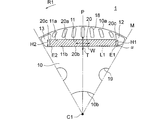
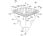
磁石挿入孔11の周方向の中心は、極中心Pである。極中心Pを通る径方向の直線を、磁極中心線と称する。隣り合う磁極の間は、極間Mである。磁石挿入孔11は、磁極中心線に直交する方向に延在している。
The center of the magnet insertion hole 11 in the circumferential direction is the polar center P. A straight line in the radial direction passing through the pole center P is referred to as a magnetic pole center line. The space between adjacent magnetic poles is M between poles. The magnet insertion hole 11 extends in a direction orthogonal to the magnetic pole center line.
磁石挿入孔11の径方向外側には、スリット17が形成されている。スリット17は、永久磁石20からステータ5に向かう磁束の分布を滑らかにし、トルク脈動を抑制するためのものである。ここでは7本のスリット17が極中心Pに対して対称に形成されているが、スリット17の数および配置は任意である。また、ロータコア10にスリット17を設けない構成も可能である。
A slit 17 is formed on the radial outer side of the magnet insertion hole 11. The slit 17 is for smoothing the distribution of the magnetic flux from the permanent magnet 20 toward the stator 5 and suppressing torque pulsation. Here, the seven slits 17 are formed symmetrically with respect to the polar center P, but the number and arrangement of the slits 17 are arbitrary. Further, it is possible to configure the rotor core 10 without providing the slit 17.
磁石挿入孔11の周方向の一方の側には、空隙12が形成されている。磁石挿入孔11の周方向の他方の側には、空隙13が形成されている。空隙12は、ロータ1の回転方向における上流側に位置し、空隙13は、ロータ1の回転方向における下流側に位置する。空隙12は第1の空隙とも称し、空隙13は第2の空隙とも称する。
A gap 12 is formed on one side of the magnet insertion hole 11 in the circumferential direction. A gap 13 is formed on the other side of the magnet insertion hole 11 in the circumferential direction. The gap 12 is located on the upstream side in the rotation direction of the rotor 1, and the gap 13 is located on the downstream side in the rotation direction of the rotor 1. The void 12 is also referred to as a first void, and the void 13 is also referred to as a second void.
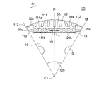
図3は、ロータ1の1磁極に対応する領域、すなわち1つの磁石挿入孔11を含む領域を示す図である。永久磁石20は、径方向外側の磁極面20aと、径方向内側の磁極面20bと、周方向の両端面20cとを有する。磁極面20aは第1磁極面とも称し、磁極面20bは第2磁極面とも称する。磁極面20a,20bは、磁極中心線に直交する方向に延在している。
FIG. 3 is a diagram showing a region corresponding to one magnetic pole of the rotor 1, that is, a region including one magnet insertion hole 11. The permanent magnet 20 has a magnetic pole surface 20a on the outer side in the radial direction, a magnetic pole surface 20b on the inner side in the radial direction, and both end surfaces 20c in the circumferential direction. The magnetic pole surface 20a is also referred to as a first magnetic pole surface, and the magnetic pole surface 20b is also referred to as a second magnetic pole surface. The magnetic pole surfaces 20a and 20b extend in a direction orthogonal to the magnetic pole center line.
永久磁石20は平板状であり、軸方向に長さを有し、軸方向に直交する面において厚さおよび幅を有する。永久磁石20の軸方向長さは、例えば30~40mmである。永久磁石20の厚さは、例えば2mmである。永久磁石20の幅は、例えば20mmである。
The permanent magnet 20 has a flat plate shape, has a length in the axial direction, and has a thickness and a width in a plane orthogonal to the axial direction. The axial length of the permanent magnet 20 is, for example, 30 to 40 mm. The thickness of the permanent magnet 20 is, for example, 2 mm. The width of the permanent magnet 20 is, for example, 20 mm.
永久磁石20の厚さ方向を、磁石厚さ方向Tと称する。磁石厚さ方向Tは、永久磁石20の磁化方向である。磁石厚さ方向Tは、また、永久磁石20の磁極面20aに直交する方向と言うこともできる。実施の形態1では、磁石厚さ方向Tは、磁極中心線と平行である。
The thickness direction of the permanent magnet 20 is referred to as the magnet thickness direction T. The magnet thickness direction T is the magnetization direction of the permanent magnet 20. The magnet thickness direction T can also be said to be a direction orthogonal to the magnetic pole surface 20a of the permanent magnet 20. In the first embodiment, the magnet thickness direction T is parallel to the magnetic pole center line.
永久磁石20の幅方向を、磁石幅方向Wと称する。磁石幅方向Wは、軸方向に直交する面内で磁極面20aと平行な方向である。また、磁石挿入孔11の延在方向は、磁石幅方向Wと一致している。実施の形態1では、磁石幅方向Wは、磁極中心線に直交している。
The width direction of the permanent magnet 20 is referred to as the magnet width direction W. The magnet width direction W is a direction parallel to the magnetic pole surface 20a in a plane orthogonal to the axial direction. Further, the extending direction of the magnet insertion hole 11 coincides with the magnet width direction W. In the first embodiment, the magnet width direction W is orthogonal to the magnetic pole center line.
なお、永久磁石20の磁極面20aと端面20cとの間の角部、および磁極面20bと端面20cとの間の角部は、磁石挿入孔11への挿入時に周囲と接触して欠けるのを抑制するため、丸められている(Rが付けられている)ことが望ましい。
The corner portion between the magnetic pole surface 20a and the end surface 20c of the permanent magnet 20 and the corner portion between the magnetic pole surface 20b and the end surface 20c are not chipped in contact with the surroundings when they are inserted into the magnet insertion hole 11. It is desirable that it is rounded (marked with R) in order to suppress it.
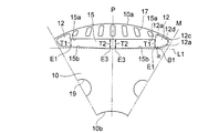
図4は、ロータコア10の1磁極に対応する領域を示す図である。磁石挿入孔11は、径方向外側の外側端辺11aと、径方向内側の内側端辺11bとを有する。外側端辺11aは、磁極中心線に直交する方向に直線状に延在している。一方、内側端辺11bは、外側端辺11aに対して傾斜して延在している。
FIG. 4 is a diagram showing a region corresponding to one magnetic pole of the rotor core 10. The magnet insertion hole 11 has an outer end side 11a on the outer side in the radial direction and an inner end side 11b on the inner side in the radial direction. The outer end edge 11a extends linearly in a direction orthogonal to the magnetic pole center line. On the other hand, the inner end side 11b is inclined and extends with respect to the outer end side 11a.
磁石厚さ方向Tにおける磁石挿入孔11の寸法を、開口寸法と称する。開口寸法は、外側端辺11aと内側端辺11bとの磁石厚さ方向Tの距離でもある。磁石挿入孔11の空隙12側の端部を端部E1と称し、磁石挿入孔11の空隙13側の端部を端部E2と称する。
The dimension of the magnet insertion hole 11 in the magnet thickness direction T is referred to as an opening dimension. The opening dimension is also the distance between the outer edge 11a and the inner edge 11b in the magnet thickness direction T. The end of the magnet insertion hole 11 on the gap 12 side is referred to as an end E1, and the end of the magnet insertion hole 11 on the gap 13 side is referred to as an end E2.
磁石挿入孔11の空隙12側の端部E1での開口寸法T1は、磁石挿入孔11の空隙13側の端部E2での開口寸法T2よりも小さい(T1<T2)。
The opening size T1 at the end E1 of the magnet insertion hole 11 on the gap 12 side is smaller than the opening size T2 at the end E2 of the magnet insertion hole 11 on the gap 13 side (T1 <T2).
具体的には、磁石挿入孔11の空隙12側の端部E1での開口寸法T1は、2.05mmであり、磁石挿入孔11の空隙13側の端部E2での開口寸法T2は、2.2mmである。
Specifically, the opening dimension T1 at the end E1 on the gap 12 side of the magnet insertion hole 11 is 2.05 mm, and the opening dimension T2 at the end E2 on the gap 13 side of the magnet insertion hole 11 is 2. It is .2 mm.
なお、開口寸法T1は、磁石挿入孔11の磁石幅方向Wの一端における開口寸法に相当する。一方、開口寸法T2は、磁石挿入孔11の磁石幅方向Wの当該一端から永久磁石20の幅だけ離間した位置(ここでは端部E2)における開口寸法に相当する。
The opening size T1 corresponds to the opening size at one end of the magnet insertion hole 11 in the magnet width direction W. On the other hand, the opening dimension T2 corresponds to the opening dimension at a position (here, the end portion E2) separated from the one end of the magnet insertion hole 11 in the magnet width direction W by the width of the permanent magnet 20.
図3に示したように、磁石挿入孔11の空隙13側の端部E2では、磁石挿入孔11の内側端辺11bと永久磁石20の磁極面20bとの間に隙間が生じる。隙間は、例えば0.2mmである。
As shown in FIG. 3, at the end E2 on the gap 13 side of the magnet insertion hole 11, a gap is formed between the inner end side 11b of the magnet insertion hole 11 and the magnetic pole surface 20b of the permanent magnet 20. The gap is, for example, 0.2 mm.
一方、磁石挿入孔11の空隙12側の端部E1では、永久磁石20が磁石挿入孔11に軽圧入された状態となる。
On the other hand, at the end E1 on the gap 12 side of the magnet insertion hole 11, the permanent magnet 20 is lightly press-fitted into the magnet insertion hole 11.
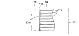
図5は、磁石挿入孔11の空隙12側の端部E1における、磁石挿入孔11と永久磁石20との軽圧入状態を示す模式図である。ロータコア10は、複数の鋼板110を軸方向に積層したものであり、積層方向に平行な断面で見ると、鋼板110の端辺の位置にはずれが生じる。
FIG. 5 is a schematic view showing a light press-fitting state of the magnet insertion hole 11 and the permanent magnet 20 at the end E1 on the gap 12 side of the magnet insertion hole 11. The rotor core 10 is formed by laminating a plurality of steel plates 110 in the axial direction, and when viewed in a cross section parallel to the laminating direction, the positions of the end edges of the steel plates 110 are displaced.
そのため、磁石挿入孔11の内側端辺11bと永久磁石20の磁極面20bとの間には、平均で例えば0.05mmの隙間があり、何枚かの鋼板110の端縁は永久磁石20の磁極面20bに当接している。このような状態を、永久磁石20が磁石挿入孔11に軽圧入された状態と称する。これにより、永久磁石20は、磁石挿入孔11の空隙12側の端部E1で保持される。
Therefore, there is an average gap of, for example, 0.05 mm between the inner end side 11b of the magnet insertion hole 11 and the magnetic pole surface 20b of the permanent magnet 20, and the edge of some steel plates 110 is the permanent magnet 20. It is in contact with the magnetic pole surface 20b. Such a state is referred to as a state in which the permanent magnet 20 is lightly press-fitted into the magnet insertion hole 11. As a result, the permanent magnet 20 is held at the end E1 on the gap 12 side of the magnet insertion hole 11.
図6は、磁石挿入孔11とその周囲を拡大して示す図である。外側端辺11aと平行な仮想線を、直線L1と称する。また、図6では、内側端辺11bを延長した直線を、直線L2で表している。内側端辺11bは、直線L1に対して角度αだけ傾斜している。言い換えると、内側端辺11bは、外側端辺11aに対して角度αだけ傾斜している。
FIG. 6 is an enlarged view of the magnet insertion hole 11 and its surroundings. The virtual line parallel to the outer edge 11a is referred to as a straight line L1. Further, in FIG. 6, a straight line extending the inner end side 11b is represented by a straight line L2. The inner edge 11b is inclined by an angle α with respect to the straight line L1. In other words, the inner edge 11b is inclined by an angle α with respect to the outer edge 11a.
空隙12は、磁石挿入孔11の外側端辺11aの端部から延在する外側端辺12aと、内側端辺11bの端部から延在する内側端辺12bと、内側端辺12bの端部から延在する極間端辺12cと、内側端辺12bおよび極間端辺12cの端部同士を結ぶように延在する外周端辺12dとを有する。
The gap 12 has an outer end 12a extending from the outer end 11a of the magnet insertion hole 11, an inner end 12b extending from the inner end 11b, and an inner end 12b. It has an inter-pole end side 12c extending from the outside and an outer peripheral end side 12d extending so as to connect the ends of the inner end side 12b and the inter-pole end side 12c.
図6では、内側端辺12bを延長した直線を、直線L3で表している。内側端辺12bは、直線L1に対し、角度αよりも大きい角度βだけ傾斜している。そのため、内側端辺11bと内側端辺12bとの境界を端点B1とすると、永久磁石20は端点B1よりも空隙12側には移動しない。すなわち、端点B1において、永久磁石20の磁石幅方向Wの位置が規制される。
In FIG. 6, a straight line extending the inner end side 12b is represented by a straight line L3. The inner edge 12b is inclined with respect to the straight line L1 by an angle β larger than the angle α. Therefore, if the boundary between the inner end side 11b and the inner end side 12b is the end point B1, the permanent magnet 20 does not move to the void 12 side of the end point B1. That is, at the end point B1, the position of the permanent magnet 20 in the magnet width direction W is regulated.
空隙12の外側端辺12aは、磁極中心線と平行に延在する。極間端辺12cは、極間Mを通る径方向の直線と平行に延在する。外周端辺12dは、ロータコア10の外周に沿って延在する。但し、これらの端辺12a,12c,12dの延在方向は、ここで説明した例に限定されるものではない。
The outer edge 12a of the gap 12 extends parallel to the center line of the magnetic pole. The interpole end edge 12c extends parallel to the radial straight line passing through the interpole M. The outer peripheral edge 12d extends along the outer circumference of the rotor core 10. However, the extending directions of these end sides 12a, 12c, 12d are not limited to the examples described here.
空隙13は、磁石挿入孔11の外側端辺11aの端部から延在する外側端辺13aと、内側端辺11bの端部から延在する内側端辺13bと、内側端辺13bの端部から延在する極間端辺13cと、内側端辺13bおよび極間端辺13cの端部同士を結ぶ外周端辺13dとを有する。
The gap 13 includes an outer end side 13a extending from the outer end side 11a of the magnet insertion hole 11, an inner end side 13b extending from the end portion of the inner end side 11b, and an end portion of the inner end side 13b. It has an inter-pole end side 13c extending from the outside and an outer peripheral end side 13d connecting the ends of the inner end side 13b and the inter-pole end side 13c.
内側端辺11bと内側端辺13bとの境界を端点B2とすると、内側端辺13bは、端点B2から、内側端辺11bと同一直線状に延在する。後述する永久磁石20の挿入工程において、永久磁石20を磁石挿入孔11の端部E2から空隙13側にはみ出すように挿入し、その後、端部E1に向けて移動させることができる。
Assuming that the boundary between the inner end side 11b and the inner end side 13b is the end point B2, the inner end side 13b extends from the end point B2 in the same linear shape as the inner end side 11b. In the process of inserting the permanent magnet 20 described later, the permanent magnet 20 can be inserted so as to protrude from the end E2 of the magnet insertion hole 11 toward the gap 13 side, and then moved toward the end E1.
空隙13の外側端辺13aは、磁極中心線に平行に延在する。極間端辺13cは、極間Mを通る径方向の直線に平行に延在する。外周端辺13dは、ロータコア10の外周に沿って延在する。但し、これらの端辺13a,13c,13dの延在方向は、ここで説明した例に限定されるものではない。
The outer edge 13a of the gap 13 extends parallel to the center line of the magnetic pole. The interpole end edge 13c extends parallel to a straight line in the radial direction passing through the interpole M. The outer peripheral edge 13d extends along the outer circumference of the rotor core 10. However, the extending directions of these end sides 13a, 13c, 13d are not limited to the examples described here.
磁石挿入孔11の開口寸法T1の狭い端部E1は、ロータ1の回転方向の上流側に位置することが望ましい。ロータ1の回転時には、磁石挿入孔11内の永久磁石20には、回転方向と逆方向の慣性力が作用する。この慣性力によって永久磁石20が磁石挿入孔11の端部E1側に付勢され、より強く圧入される。
It is desirable that the narrow end E1 of the opening dimension T1 of the magnet insertion hole 11 is located on the upstream side in the rotation direction of the rotor 1. When the rotor 1 rotates, an inertial force in the direction opposite to the rotation direction acts on the permanent magnet 20 in the magnet insertion hole 11. The permanent magnet 20 is urged toward the end E1 side of the magnet insertion hole 11 by this inertial force, and is press-fitted more strongly.
<ロータの製造方法>
次に、ロータ1の製造方法について説明する。図7は、ロータ1の製造方法を示すフローチャートである。まず、図2に示した平面形状に打ち抜かれた複数の鋼板を軸方向に積層する。積層した鋼板をカシメ等により一体に固定することにより、ロータコア10を形成する(ステップS10)。次に、ロータコア10の磁石挿入孔11に、永久磁石20を挿入する(ステップS20)。 <Rotor manufacturing method>
Next, a method of manufacturing therotor 1 will be described. FIG. 7 is a flowchart showing a manufacturing method of the rotor 1. First, a plurality of steel plates punched into the planar shape shown in FIG. 2 are laminated in the axial direction. The rotor core 10 is formed by integrally fixing the laminated steel plates by caulking or the like (step S10). Next, the permanent magnet 20 is inserted into the magnet insertion hole 11 of the rotor core 10 (step S20).
次に、ロータ1の製造方法について説明する。図7は、ロータ1の製造方法を示すフローチャートである。まず、図2に示した平面形状に打ち抜かれた複数の鋼板を軸方向に積層する。積層した鋼板をカシメ等により一体に固定することにより、ロータコア10を形成する(ステップS10)。次に、ロータコア10の磁石挿入孔11に、永久磁石20を挿入する(ステップS20)。 <Rotor manufacturing method>
Next, a method of manufacturing the
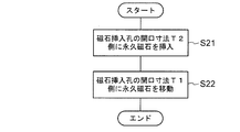
図8は、永久磁石20の挿入工程を示すフローチャートである。図9(A)~(C)は、永久磁石20の挿入工程を示す模式図である。図9(A)に示すように、磁石挿入孔11は、空隙12側の端部E1における開口寸法T1が、空隙13側の端部E2における開口寸法T2よりも小さい。
FIG. 8 is a flowchart showing the insertion process of the permanent magnet 20. 9 (A) to 9 (C) are schematic views showing an insertion process of the permanent magnet 20. As shown in FIG. 9A, the magnet insertion hole 11 has an opening dimension T1 at the end E1 on the gap 12 side smaller than the opening dimension T2 at the end E2 on the gap 13 side.
まず、図9(B)に示すように、永久磁石20を磁石挿入孔11の開口寸法の広い端部E2側すなわち空隙13側に挿入する(ステップS21)。永久磁石20は、空隙13側にはみ出すように、磁石挿入孔11に挿入される。
First, as shown in FIG. 9B, the permanent magnet 20 is inserted into the wide end E2 side, that is, the gap 13 side of the magnet insertion hole 11 (step S21). The permanent magnet 20 is inserted into the magnet insertion hole 11 so as to protrude toward the gap 13.
次に、図9(C)に矢印Aで示すように、永久磁石20を磁石挿入孔11の開口寸法の小さい端部E1側すなわち空隙12側に移動させる(ステップS22)。永久磁石20を空隙12側に移動させると、磁石挿入孔11の幅が徐々に狭まる。
Next, as shown by the arrow A in FIG. 9C, the permanent magnet 20 is moved to the end E1 side, that is, the gap 12 side, where the opening size of the magnet insertion hole 11 is small (step S22). When the permanent magnet 20 is moved to the gap 12 side, the width of the magnet insertion hole 11 gradually narrows.
永久磁石20を空隙12側に移動させることにより、永久磁石20の移動方向の前端部分が磁石挿入孔11の端辺11a,11bの間に軽圧入された状態となる。これにより、永久磁石20は磁石挿入孔11内で移動しないように位置決めされる。
By moving the permanent magnet 20 toward the gap 12, the front end portion of the permanent magnet 20 in the moving direction is lightly press-fitted between the end sides 11a and 11b of the magnet insertion hole 11. As a result, the permanent magnet 20 is positioned so as not to move in the magnet insertion hole 11.
また、内側端辺11bの端点B1の先は傾斜角度の大きい内側端辺12bであるため、永久磁石20を端点B1から空隙12側に移動させることはできない。すなわち、永久磁石20の周方向位置が端点B1によって規定される。
Further, since the tip of the end point B1 of the inner end side 11b is the inner end side 12b having a large inclination angle, the permanent magnet 20 cannot be moved from the end point B1 to the void 12 side. That is, the circumferential position of the permanent magnet 20 is defined by the end point B1.
このように磁石挿入孔11に永久磁石20を挿入したのち、図7のステップS30において、ロータコア10の内周10bにシャフト25を焼嵌め等によって固定する(S30)。ロータコア10にシャフト25を固定した後、永久磁石20の着磁を行ってもよい。永久磁石20の着磁は、着磁装置を用いて行ってもよく、ロータ1をステータ5に組み込んだ状態で行ってもよい。あるいは、永久磁石20を着磁した後に、ロータコア10にシャフト25を固定してもよい。
After inserting the permanent magnet 20 into the magnet insertion hole 11 in this way, in step S30 of FIG. 7, the shaft 25 is fixed to the inner circumference 10b of the rotor core 10 by shrink fitting or the like (S30). After fixing the shaft 25 to the rotor core 10, the permanent magnet 20 may be magnetized. The magnetizing of the permanent magnet 20 may be performed using a magnetizing device, or may be performed with the rotor 1 incorporated in the stator 5. Alternatively, the shaft 25 may be fixed to the rotor core 10 after the permanent magnet 20 is magnetized.
<作用>
次に、実施の形態1の作用について説明する。図10は、実施の形態1のロータ1と対比する比較例1のロータ1Dの1磁極に相当する領域を示す図である。比較例1のロータ1Dは、磁石挿入孔111および空隙112の形状において、実施の形態1のロータ1と異なる。 <Action>
Next, the operation of the first embodiment will be described. FIG. 10 is a diagram showing a region corresponding to one magnetic pole of therotor 1D of Comparative Example 1 in comparison with the rotor 1 of the first embodiment. The rotor 1D of Comparative Example 1 is different from the rotor 1 of the first embodiment in the shape of the magnet insertion hole 111 and the gap 112.
次に、実施の形態1の作用について説明する。図10は、実施の形態1のロータ1と対比する比較例1のロータ1Dの1磁極に相当する領域を示す図である。比較例1のロータ1Dは、磁石挿入孔111および空隙112の形状において、実施の形態1のロータ1と異なる。 <Action>
Next, the operation of the first embodiment will be described. FIG. 10 is a diagram showing a region corresponding to one magnetic pole of the
比較例1の磁石挿入孔111は、磁石厚さ方向Tの幅が、磁石幅方向Wの全域において一定である。すなわち、磁石挿入孔11の外側端辺111aと内側端辺111bとは、互いに平行である。磁石挿入孔111の周方向両側には、極中心Pに対して対称な形状の2つの空隙112が形成されている。
In the magnet insertion hole 111 of Comparative Example 1, the width in the magnet thickness direction T is constant over the entire area in the magnet width direction W. That is, the outer end side 111a and the inner end side 111b of the magnet insertion hole 11 are parallel to each other. Two voids 112 having a shape symmetrical with respect to the polar center P are formed on both sides of the magnet insertion hole 111 in the circumferential direction.
永久磁石20の厚さには、加工時に生じるばらつきがある。特に、希土類磁石は、ブロック状の焼結磁石から平板状に切断されて製造されるため、加工誤差により0.2mm程度の寸法公差がある。そのため、磁石挿入孔111の開口寸法は、一般に、永久磁石20の厚さよりも大きく設定される。これにより、永久磁石20と磁石挿入孔111との間には、磁石厚さ方向T(永久磁石20の磁化方向)の隙間が生じる。
The thickness of the permanent magnet 20 varies during processing. In particular, since rare earth magnets are manufactured by cutting them into flat plates from block-shaped sintered magnets, they have a dimensional tolerance of about 0.2 mm due to processing errors. Therefore, the opening size of the magnet insertion hole 111 is generally set to be larger than the thickness of the permanent magnet 20. As a result, a gap in the magnet thickness direction T (magnetization direction of the permanent magnet 20) is generated between the permanent magnet 20 and the magnet insertion hole 111.
この隙間は永久磁石20から出る磁束に対してエアギャップとなるため、ステータ5のコイル55に鎖交する磁束を減少させ、コイル55における誘起電圧が低下する。その結果、同一出力を発生するために必要な電流が増加し、これにより銅損が増加し、モータ効率が低下する。
Since this gap becomes an air gap with respect to the magnetic flux emitted from the permanent magnet 20, the magnetic flux interlinking with the coil 55 of the stator 5 is reduced, and the induced voltage in the coil 55 is lowered. As a result, the current required to generate the same output increases, which increases copper loss and reduces motor efficiency.
また、上記のように永久磁石20と磁石挿入孔111との間に隙間があると、永久磁石20が磁石挿入孔111内で移動しやすく、ロータコア10にぶつかって振動が発生する可能性がある。そのため、磁石挿入孔111あるいは空隙112には、永久磁石20の端面20cに当接する突起113が設けられている。このように突起113を設けると、以下のように永久磁石20の減磁が生じる可能性がある。
Further, if there is a gap between the permanent magnet 20 and the magnet insertion hole 111 as described above, the permanent magnet 20 easily moves in the magnet insertion hole 111 and may hit the rotor core 10 to generate vibration. .. Therefore, the magnet insertion hole 111 or the gap 112 is provided with a protrusion 113 that abuts on the end face 20c of the permanent magnet 20. When the protrusion 113 is provided in this way, the permanent magnet 20 may be demagnetized as follows.
モータ100では、ステータ5のコイル55に通常運転時よりも大きな電流が流れる場合がある。ステータ5のコイル55に大きな電流が流れると、コイル55の電流によって発生した磁束が永久磁石20に作用する。永久磁石20に着磁方向と反対方向に流れる磁束を、逆磁束と称する。
In the motor 100, a larger current may flow through the coil 55 of the stator 5 than in normal operation. When a large current flows through the coil 55 of the stator 5, the magnetic flux generated by the current of the coil 55 acts on the permanent magnet 20. The magnetic flux flowing through the permanent magnet 20 in the direction opposite to the magnetizing direction is called a reverse magnetic flux.
ステータ5からの逆磁束は、ロータコア10内で少しでも磁気抵抗の小さい部分を流れようとするため、磁気抵抗の大きい磁石挿入孔111および空隙112を迂回し、空隙112とロータコア10の外周10aとの間の薄肉部に向かう。しかしながら、薄肉部は磁路が狭いため、一定の磁束が流れると磁気飽和し、磁束が流れなくなる。
Since the reverse magnetic flux from the stator 5 tends to flow in the rotor core 10 through a portion having a small reluctance, it bypasses the magnet insertion hole 111 and the gap 112 having a large magnetic resistance, and the gap 112 and the outer circumference 10a of the rotor core 10 Head to the thin part between. However, since the magnetic path is narrow in the thin-walled portion, magnetic saturation occurs when a constant magnetic flux flows, and the magnetic flux does not flow.
上記のように磁石挿入孔111あるいは空隙12に突起113を設けると、ロータコア10の外周領域から突起113までの距離が永久磁石20の厚さよりも小さくなるため、ステータ5からの逆磁束が突起113に集中して流れる。突起113は永久磁石20の端面20cに接しているため、突起113に逆磁束が集中すると、永久磁石20の端面20cの減磁が生じる。
When the protrusion 113 is provided in the magnet insertion hole 111 or the gap 12 as described above, the distance from the outer peripheral region of the rotor core 10 to the protrusion 113 is smaller than the thickness of the permanent magnet 20, so that the reverse magnetic flux from the stator 5 is generated by the protrusion 113. Concentrate on the flow. Since the protrusion 113 is in contact with the end face 20c of the permanent magnet 20, when the reverse magnetic flux is concentrated on the protrusion 113, the end face 20c of the permanent magnet 20 is demagnetized.
永久磁石20の減磁は、特に高温で発生しやすい。永久磁石20の減磁が生じると、永久磁石20の残留磁束密度が低下し、逆磁束がなくなった後も元に戻らなくなる。そのため、永久磁石20の減磁はモータ100の出力低下につながり、圧縮機300あるいは空気調和装置400の性能低下の原因となる。
Demagnetization of the permanent magnet 20 is likely to occur especially at high temperatures. When the permanent magnet 20 is demagnetized, the residual magnetic flux density of the permanent magnet 20 decreases, and even after the reverse magnetic flux disappears, it cannot be restored. Therefore, the demagnetization of the permanent magnet 20 leads to a decrease in the output of the motor 100, which causes a decrease in the performance of the compressor 300 or the air conditioner 400.
これに対し、実施の形態1では、図3に示したように、磁石挿入孔11の磁石幅方向Wの一方の端部E1での開口寸法T1が、他方の端部E2での開口寸法T2よりも小さい。そのため、永久磁石20を磁石挿入孔11の端部E2側に挿入してから、端部E1側に移動させることができる。
On the other hand, in the first embodiment, as shown in FIG. 3, the opening dimension T1 at one end E1 of the magnet width direction W of the magnet insertion hole 11 is the opening dimension T2 at the other end E2. Smaller than Therefore, the permanent magnet 20 can be inserted into the end E2 side of the magnet insertion hole 11 and then moved to the end E1 side.
永久磁石20が磁石挿入孔11の端部E1側において軽圧入状態で保持されるため、永久磁石20と磁石挿入孔11との隙間を狭くすることができ、その結果、磁気抵抗が減少する。これにより、ステータ5のコイル55に鎖交する磁束量が増加する。コイル55に鎖交する磁束量の増加により、同一トルクを発生させるためにコイル55に流す電流を少なくすることができ、これにより銅損を低減し、モータ効率を向上することができる。
Since the permanent magnet 20 is held in a light press-fitted state at the end E1 side of the magnet insertion hole 11, the gap between the permanent magnet 20 and the magnet insertion hole 11 can be narrowed, and as a result, the magnetic resistance is reduced. As a result, the amount of magnetic flux interlinking with the coil 55 of the stator 5 increases. By increasing the amount of magnetic flux interlinking with the coil 55, it is possible to reduce the current flowing through the coil 55 in order to generate the same torque, thereby reducing copper loss and improving motor efficiency.
また、磁石挿入孔11の開口寸法T1の端部E1側で永久磁石20が軽圧入状態で保持されるため、比較例1のような突起113を設ける必要がない。磁石挿入孔11内に突出する部分、すなわちステータ5からの逆磁束が集中する部分を有さないため、永久磁石20の減磁が発生しにくい。
Further, since the permanent magnet 20 is held in a light press-fitting state on the end E1 side of the opening dimension T1 of the magnet insertion hole 11, it is not necessary to provide the protrusion 113 as in Comparative Example 1. Since there is no portion protruding into the magnet insertion hole 11, that is, a portion where the reverse magnetic flux from the stator 5 is concentrated, demagnetization of the permanent magnet 20 is unlikely to occur.
このように実施の形態1のロータ1では、磁石挿入孔11内に突起を設けなくても永久磁石20を位置決めすることができるため、永久磁石20の減磁を抑制することができる。また、永久磁石20と磁石挿入孔11との隙間が小さいため、モータ効率を向上することができる。
As described above, in the rotor 1 of the first embodiment, since the permanent magnet 20 can be positioned without providing a protrusion in the magnet insertion hole 11, demagnetization of the permanent magnet 20 can be suppressed. Further, since the gap between the permanent magnet 20 and the magnet insertion hole 11 is small, the motor efficiency can be improved.
また、磁石挿入孔11あるいは空隙12,13内に突起を設けた場合、永久磁石20から出た磁束が突起を介して永久磁石20に戻ってしまう、いわゆる磁束の短絡が生じる可能性があるが、実施の形態1では磁石挿入孔11および空隙12,13内に突起を設ける必要がないため、磁束の短絡を抑制し、モータ効率を向上することができる。
Further, when the protrusions are provided in the magnet insertion holes 11 or the gaps 12 and 13, the magnetic flux emitted from the permanent magnet 20 may return to the permanent magnet 20 via the protrusions, that is, a so-called short circuit of magnetic flux may occur. In the first embodiment, since it is not necessary to provide protrusions in the magnet insertion holes 11 and the gaps 12 and 13, short-circuiting of magnetic flux can be suppressed and motor efficiency can be improved.
図11は、実施の形態1と比較例1とで、ステータ5のコイル55に鎖交する磁束量を比較して示すグラフである。縦軸は、実施の形態1のロータ1と比較例1のロータ1Dとをそれぞれステータ5(図1)に組み込んだ場合に、ステータ5のコイル55に鎖交する磁束量を相対値で示している。
FIG. 11 is a graph showing a comparison of the amount of magnetic flux interlinking with the coil 55 of the stator 5 between the first embodiment and the first comparative example. The vertical axis indicates the amount of magnetic flux interlinking with the coil 55 of the stator 5 as a relative value when the rotor 1 of the first embodiment and the rotor 1D of the comparative example 1 are respectively incorporated in the stator 5 (FIG. 1). There is.
比較例1においてステータ5のコイル55に鎖交する磁束量を100%とする。図11から明らかなように、実施の形態1では、ステータ5のコイル55に鎖交する磁束量は、比較例1の100%に対して103%に増加している。
In Comparative Example 1, the amount of magnetic flux interlinking with the coil 55 of the stator 5 is 100%. As is clear from FIG. 11, in the first embodiment, the amount of magnetic flux interlinking with the coil 55 of the stator 5 is increased to 103% with respect to 100% of Comparative Example 1.
これは、実施の形態1のロータ1では、永久磁石20と磁石挿入孔11との隙間が小さいため、磁気抵抗が減少し、ステータ5のコイル55への鎖交磁束が増加したことによる。
This is because in the rotor 1 of the first embodiment, since the gap between the permanent magnet 20 and the magnet insertion hole 11 is small, the magnetic resistance is reduced and the interlinkage magnetic flux to the coil 55 of the stator 5 is increased.
図12は、実施の形態1と比較例1とで、3%減磁電流を比較して示すグラフである。3%減磁電流は、永久磁石20の減磁率が3%に達したときにコイル55に流れている電流である。モータ100は140℃の雰囲気中に置いている。この温度(140℃)は、モータ100が圧縮機300内で使用される場合の最高温度である。
FIG. 12 is a graph showing a comparison of 3% demagnetization current between the first embodiment and the first comparative example. The 3% demagnetization current is the current flowing through the coil 55 when the demagnetization rate of the permanent magnet 20 reaches 3%. The motor 100 is placed in an atmosphere of 140 ° C. This temperature (140 ° C.) is the maximum temperature when the motor 100 is used in the compressor 300.
上記の通り、永久磁石20の減磁は、モータ100の出力低下につながり、圧縮機300あるいは空気調和装置400の性能低下の原因となる。そのため、一般に、モータ100の減磁率は3%以下に抑えることが求められている。また、モータ100を制御するインバータ回路には、減磁率が3%に達する前に電流を遮断する電流遮断回路が設けられている。
As described above, the demagnetization of the permanent magnet 20 leads to a decrease in the output of the motor 100, which causes a decrease in the performance of the compressor 300 or the air conditioner 400. Therefore, in general, the demagnetization rate of the motor 100 is required to be suppressed to 3% or less. Further, the inverter circuit that controls the motor 100 is provided with a current cutoff circuit that cuts off the current before the demagnetization rate reaches 3%.
図12から明らかなように、比較例1のロータ1Dを用いた場合の3%電流を100%とすると、実施の形態1のロータ1を用いた場合の3%減磁電流は、102%に増加している。
As is clear from FIG. 12, assuming that the 3% current when the rotor 1D of Comparative Example 1 is used is 100%, the 3% demagnetization current when the rotor 1 of the first embodiment is used is 102%. It has increased.
これは、実施の形態1のロータ1では、磁石挿入孔11あるいは空隙12に突起113(図10)が設けられていないため、永久磁石20の周囲にステータ5からの逆磁束の集中する部分が存在しないことによる。
This is because in the rotor 1 of the first embodiment, since the protrusion 113 (FIG. 10) is not provided in the magnet insertion hole 11 or the gap 12, there is a portion where the reverse magnetic flux from the stator 5 is concentrated around the permanent magnet 20. Because it doesn't exist.
なお、磁石挿入孔11の端部E2側では、永久磁石20と磁石挿入孔11との間に隙間が生じるが、磁石挿入孔11の開口寸法T1の端部E1側で永久磁石20が軽圧入状態で保持されるため、永久磁石20の磁石厚さ方向Tのがたつきを抑制することができる。
A gap is formed between the permanent magnet 20 and the magnet insertion hole 11 on the end E2 side of the magnet insertion hole 11, but the permanent magnet 20 is lightly press-fitted on the end E1 side of the opening dimension T1 of the magnet insertion hole 11. Since it is held in the state, it is possible to suppress rattling of the permanent magnet 20 in the magnet thickness direction T.
磁石挿入孔11の内側端辺11bは、その全体が直線L1に対して傾斜していることが望ましいが、端部E1での開口寸法T1が端部E2での開口寸法T2よりも小さければ、内側端辺11bの一部だけが直線L1に対して傾斜していてもよい。
It is desirable that the entire inner end side 11b of the magnet insertion hole 11 is inclined with respect to the straight line L1, but if the opening dimension T1 at the end E1 is smaller than the opening dimension T2 at the end E2, Only a part of the inner end side 11b may be inclined with respect to the straight line L1.
<実施の形態の効果>
以上説明したように、実施の形態1のロータ1は、磁石挿入孔11を有する環状のロータコア10と、磁石挿入孔11に配置された永久磁石20とを有し、永久磁石20は軸線C1に直交する面において厚さおよび幅を有する。磁石挿入孔11は、周方向の一方の端部E1における開口寸法T1が、当該端部E1から永久磁石20の幅Wだけ離れた位置(ここでは端部E2)における開口寸法T2よりも小さくなるように、内側端辺11bが磁石幅方向Wに対して傾斜している。 <Effect of embodiment>
As described above, therotor 1 of the first embodiment has an annular rotor core 10 having a magnet insertion hole 11 and a permanent magnet 20 arranged in the magnet insertion hole 11, and the permanent magnet 20 is on the axis C1. It has thickness and width in orthogonal planes. In the magnet insertion hole 11, the opening dimension T1 at one end E1 in the circumferential direction is smaller than the opening dimension T2 at a position (here, the end E2) separated from the end E1 by the width W of the permanent magnet 20. As described above, the inner end side 11b is inclined with respect to the magnet width direction W.
以上説明したように、実施の形態1のロータ1は、磁石挿入孔11を有する環状のロータコア10と、磁石挿入孔11に配置された永久磁石20とを有し、永久磁石20は軸線C1に直交する面において厚さおよび幅を有する。磁石挿入孔11は、周方向の一方の端部E1における開口寸法T1が、当該端部E1から永久磁石20の幅Wだけ離れた位置(ここでは端部E2)における開口寸法T2よりも小さくなるように、内側端辺11bが磁石幅方向Wに対して傾斜している。 <Effect of embodiment>
As described above, the
そのため、永久磁石20を、磁石挿入孔11の開口寸法の小さい端部E2側に挿入してから開口寸法の広い端部E1に向けて移動させることによって、永久磁石20を磁石挿入孔11で位置決めすることができる。
Therefore, the permanent magnet 20 is positioned at the magnet insertion hole 11 by inserting the permanent magnet 20 into the end E2 side of the magnet insertion hole 11 having a small opening size and then moving the permanent magnet 20 toward the end E1 having a wide opening size. can do.
これにより、磁石挿入孔11あるいは空隙12に永久磁石20の位置決め用の突起を設ける必要がなくなり、突起にステータ5からの逆磁束が集中して生じる永久磁石20の減磁を抑制することができる。また、永久磁石20と磁石挿入孔11との隙間を小さくすることができるため、ステータ5のコイル55に鎖交する磁束量を増加させて、モータ効率を向上することができる。
This eliminates the need to provide a protrusion for positioning the permanent magnet 20 in the magnet insertion hole 11 or the gap 12, and suppresses demagnetization of the permanent magnet 20 caused by concentration of the reverse magnetic flux from the stator 5 on the protrusion. .. Further, since the gap between the permanent magnet 20 and the magnet insertion hole 11 can be reduced, the amount of magnetic flux interlinking with the coil 55 of the stator 5 can be increased, and the motor efficiency can be improved.
また、磁石挿入孔11の外側端辺11aが磁石厚さ方向Tに対して直交し、直線状に延在している。そのため、磁石挿入孔11よりも径方向外側の領域における磁束分布が極中心に対して対称となり、ロータ1の表面磁束分布を正弦波に近付けることができる。これにより、ロータ1の表面磁束の高周波成分を低減し、振動および騒音を低減することができる。
Further, the outer end side 11a of the magnet insertion hole 11 is orthogonal to the magnet thickness direction T and extends linearly. Therefore, the magnetic flux distribution in the region radially outside the magnet insertion hole 11 is symmetrical with respect to the polar center, and the surface magnetic flux distribution of the rotor 1 can be made closer to a sine wave. As a result, the high frequency component of the surface magnetic flux of the rotor 1 can be reduced, and vibration and noise can be reduced.
また、磁石挿入孔11の端部E1では、複数の鋼板110のうちの一部が永久磁石20に接触するため、永久磁石20を磁石挿入孔11内で移動しないように位置決めすることができる。
Further, at the end E1 of the magnet insertion hole 11, since a part of the plurality of steel plates 110 comes into contact with the permanent magnet 20, the permanent magnet 20 can be positioned so as not to move in the magnet insertion hole 11.
また、磁石挿入孔11の内側端辺11bに連続して、空隙12の内側端辺12bが形成されており、内側端辺11bと外側端辺11aとのなす角度βが、内側端辺12bと外側端辺11aとのなす角度αよりも大きい。そのため、内側端辺11bと内側端辺12bとの境界である端点B1で、永久磁石20の磁石幅方向Wの位置を規制することができる。
Further, the inner end side 12b of the gap 12 is formed continuously to the inner end side 11b of the magnet insertion hole 11, and the angle β formed by the inner end side 11b and the outer end side 11a is equal to the inner end side 12b. It is larger than the angle α formed by the outer edge 11a. Therefore, the position of the permanent magnet 20 in the magnet width direction W can be regulated at the end point B1 which is the boundary between the inner end side 11b and the inner end side 12b.
また、磁石挿入孔11の端部E1はロータ1の回転方向の上流側に位置するため、ロータ1の回転時に永久磁石20に作用する慣性力によって、永久磁石20が磁石挿入孔11の端部E1に押し込まれる。そのため、磁石挿入孔11内で永久磁石20を確実に位置決めすることができる。
Further, since the end E1 of the magnet insertion hole 11 is located on the upstream side in the rotation direction of the rotor 1, the permanent magnet 20 is moved to the end of the magnet insertion hole 11 by the inertial force acting on the permanent magnet 20 when the rotor 1 rotates. It is pushed into E1. Therefore, the permanent magnet 20 can be reliably positioned in the magnet insertion hole 11.
変形例.
図13は、実施の形態1の変形例のロータ1の1磁極に対応する領域を示す図である。この変形例では、永久磁石20の形状が実施の形態1と異なる。磁石挿入孔11の形状は実施の形態1の磁石挿入孔11(図4)と同じである。 Modification example.
FIG. 13 is a diagram showing a region corresponding to one magnetic pole of therotor 1 of the modified example of the first embodiment. In this modification, the shape of the permanent magnet 20 is different from that of the first embodiment. The shape of the magnet insertion hole 11 is the same as that of the magnet insertion hole 11 (FIG. 4) of the first embodiment.
図13は、実施の形態1の変形例のロータ1の1磁極に対応する領域を示す図である。この変形例では、永久磁石20の形状が実施の形態1と異なる。磁石挿入孔11の形状は実施の形態1の磁石挿入孔11(図4)と同じである。 Modification example.
FIG. 13 is a diagram showing a region corresponding to one magnetic pole of the
すなわち、この変形例では、永久磁石20の空隙12側の厚さH1が、空隙13側の厚さH2よりも薄い。永久磁石20の磁極面20aは磁石厚さ方向Tに直交し、磁極面20bは磁石厚さ方向Tに対して傾斜している。永久磁石20の磁極面20aは直線L1に平行であり、磁極面20bは直線L1に対して傾斜している。
That is, in this modified example, the thickness H1 on the gap 12 side of the permanent magnet 20 is thinner than the thickness H2 on the gap 13 side. The magnetic pole surface 20a of the permanent magnet 20 is orthogonal to the magnet thickness direction T, and the magnetic pole surface 20b is inclined with respect to the magnet thickness direction T. The magnetic pole surface 20a of the permanent magnet 20 is parallel to the straight line L1, and the magnetic pole surface 20b is inclined with respect to the straight line L1.
永久磁石20の磁極面20bの直線L1に対する傾斜角度は、磁石挿入孔11の内側端辺11bの直線L1に対する傾斜角度(角度α)と同じであることが望ましい。
It is desirable that the inclination angle of the magnetic pole surface 20b of the permanent magnet 20 with respect to the straight line L1 is the same as the inclination angle (angle α) of the inner end side 11b of the magnet insertion hole 11 with respect to the straight line L1.
この変形例では、永久磁石20が磁石挿入孔11と同様に傾斜しているため、永久磁石20と磁石挿入孔11との隙間を小さくすることができ、これにより磁気抵抗を低下させてモータ効率を向上することができる。
In this modification, since the permanent magnet 20 is inclined in the same manner as the magnet insertion hole 11, the gap between the permanent magnet 20 and the magnet insertion hole 11 can be reduced, thereby reducing the magnetic resistance and the motor efficiency. Can be improved.
また、永久磁石20が磁石挿入孔11の広い範囲で軽圧入された状態となるため、永久磁石20を磁石挿入孔11内で確実に位置決めすることができる。
Further, since the permanent magnet 20 is lightly press-fitted in a wide range of the magnet insertion hole 11, the permanent magnet 20 can be reliably positioned in the magnet insertion hole 11.
特に、永久磁石20の磁極面20bの直線L1に対する傾斜角度が、磁石挿入孔11の内側端辺11bの直線L1に対する傾斜角度と同じであれば、永久磁石20と磁石挿入孔11との隙間を最小限にし、モータ効率をさらに向上することができる。また、永久磁石20が磁石挿入孔11の広範囲に亘って軽圧入された状態となるため、永久磁石20を磁石挿入孔11内でより確実に位置決めすることができる。
In particular, if the inclination angle of the magnetic pole surface 20b of the permanent magnet 20 with respect to the straight line L1 is the same as the inclination angle of the inner end side 11b of the magnet insertion hole 11 with respect to the straight line L1, the gap between the permanent magnet 20 and the magnet insertion hole 11 is formed. It can be minimized and the motor efficiency can be further improved. Further, since the permanent magnet 20 is lightly press-fitted over a wide area of the magnet insertion hole 11, the permanent magnet 20 can be more reliably positioned in the magnet insertion hole 11.
永久磁石20の磁石挿入孔11への挿入方法は、図8および図9(A)~(C)を参照して説明したとおりである。
The method of inserting the permanent magnet 20 into the magnet insertion hole 11 is as described with reference to FIGS. 8 and 9 (A) to 9 (C).
その他の点においては、変形例のロータ1は、実施の形態1のロータ1と同様に構成されている。
In other respects, the rotor 1 of the modified example is configured in the same manner as the rotor 1 of the first embodiment.
以上説明したように、この変形例によれば、永久磁石20の磁石幅方向Wの一端が厚さH1を有し、他端が厚さH2(>H1)を有する。そのため、永久磁石20と磁石挿入孔11との隙間を小さくしてモータ効率を向上し、且つ永久磁石20を磁石挿入孔11内でより確実に位置決めすることができる。
As described above, according to this modification, one end of the permanent magnet 20 in the magnet width direction W has a thickness H1 and the other end has a thickness H2 (> H1). Therefore, the gap between the permanent magnet 20 and the magnet insertion hole 11 can be reduced to improve the motor efficiency, and the permanent magnet 20 can be more reliably positioned in the magnet insertion hole 11.
実施の形態2.
次に、実施の形態2について説明する。図14は、実施の形態2のモータ100Aを示す断面図である。実施の形態2のモータ100Aは、ロータ1AがV字状の磁石挿入孔14を有する点で実施の形態1のモータ100と異なる。実施の形態2のステータ5は、実施の形態1のステータ5と同様に構成されている。 Embodiment 2.
Next, the second embodiment will be described. FIG. 14 is a cross-sectional view showing themotor 100A of the second embodiment. The motor 100A of the second embodiment is different from the motor 100 of the first embodiment in that the rotor 1A has a V-shaped magnet insertion hole 14. The stator 5 of the second embodiment is configured in the same manner as the stator 5 of the first embodiment.
次に、実施の形態2について説明する。図14は、実施の形態2のモータ100Aを示す断面図である。実施の形態2のモータ100Aは、ロータ1AがV字状の磁石挿入孔14を有する点で実施の形態1のモータ100と異なる。実施の形態2のステータ5は、実施の形態1のステータ5と同様に構成されている。 Embodiment 2.
Next, the second embodiment will be described. FIG. 14 is a cross-sectional view showing the
図15は、実施の形態2のロータ1Aの1磁極に対応する領域を示す図である。ロータ1Aのロータコア10には、周方向中心が内周10b側に凸となるV字状の磁石挿入孔14が形成されている。磁石挿入孔14は、周方向中心を挟んで周方向に対称な形状を有する。
FIG. 15 is a diagram showing a region corresponding to one magnetic pole of the rotor 1A of the second embodiment. The rotor core 10 of the rotor 1A is formed with a V-shaped magnet insertion hole 14 whose circumferential center is convex toward the inner circumference 10b. The magnet insertion hole 14 has a shape symmetrical in the circumferential direction with the center in the circumferential direction interposed therebetween.
1つの磁石挿入孔14には、周方向中心を挟んだ両側に、2つの永久磁石21が配置されている。2つの永久磁石21は、磁化方向が同一方向である。1つの磁石挿入孔14は、1磁極を構成する。磁石挿入孔14の周方向中心は、極中心Pに相当する。
In one magnet insertion hole 14, two permanent magnets 21 are arranged on both sides of the circumferential center. The two permanent magnets 21 have the same magnetization direction. One magnet insertion hole 14 constitutes one magnetic pole. The circumferential center of the magnet insertion hole 14 corresponds to the polar center P.
各永久磁石21は、径方向外側の磁極面21aと、径方向内側の磁極面21bと、周方向の両端面21cとを有する。磁極面21a,21bは、磁極中心線に対して傾斜している。
Each permanent magnet 21 has a magnetic pole surface 21a on the outer side in the radial direction, a magnetic pole surface 21b on the inner side in the radial direction, and both end faces 21c in the circumferential direction. The magnetic pole surfaces 21a and 21b are inclined with respect to the magnetic pole center line.
永久磁石21の厚さ方向を、磁石厚さ方向Tと称する。磁石厚さ方向Tは、永久磁石21の磁化方向である。磁石厚さ方向Tは、また、永久磁石21の磁極面21aに直交する方向である。
The thickness direction of the permanent magnet 21 is referred to as the magnet thickness direction T. The magnet thickness direction T is the magnetization direction of the permanent magnet 21. The magnet thickness direction T is also a direction orthogonal to the magnetic pole surface 21a of the permanent magnet 21.
永久磁石21の幅方向を、磁石幅方向Wと称する。磁石幅方向Wは、軸方向に直交する面内で磁極面21aと平行な方向である。実施の形態2では、磁石厚さ方向Tおよび磁石幅方向Wは、磁極中心線に対して傾斜している。
The width direction of the permanent magnet 21 is referred to as the magnet width direction W. The magnet width direction W is a direction parallel to the magnetic pole surface 21a in a plane orthogonal to the axial direction. In the second embodiment, the magnet thickness direction T and the magnet width direction W are inclined with respect to the magnetic pole center line.
図16は、ロータコア10の1磁極に対応する領域を示す図である。磁石挿入孔14の周方向の両端には、空隙12がそれぞれ形成されている。2つの空隙12は、極中心Pに対して互いに対称な形状を有する。
FIG. 16 is a diagram showing a region corresponding to one magnetic pole of the rotor core 10. Air gaps 12 are formed at both ends of the magnet insertion hole 14 in the circumferential direction. The two voids 12 have a shape symmetrical with respect to the polar center P.
磁石挿入孔14は、周方向両端における磁石厚さ方向Tの開口寸法T1が、周方向中心における磁石厚さ方向Tの開口寸法T2よりも小さくなる形状を有する。
The magnet insertion hole 14 has a shape in which the opening dimension T1 in the magnet thickness direction T at both ends in the circumferential direction is smaller than the opening dimension T2 in the magnet thickness direction T at the center in the circumferential direction.
言い換えると、磁石挿入孔14は、磁石幅方向Wの端部E1における磁石厚さ方向Tの開口寸法T1が、端部E1から永久磁石21の幅だけ離間した位置E3における磁石厚さ方向Tの開口寸法T2よりも小さくなる形状を有する。
In other words, the magnet insertion hole 14 is formed in the magnet thickness direction T at the position E3 where the opening dimension T1 in the magnet thickness direction T at the end E1 in the magnet width direction W is separated from the end E1 by the width of the permanent magnet 21. It has a shape smaller than the opening size T2.
磁石挿入孔14は、径方向外側に位置する外側端辺14aと、径方向内側に位置する内側端辺14bとを有する。外側端辺14aおよび内側端辺14bはいずれも、周方向中心が内周10b側に凸となるV字状に延在している。
The magnet insertion hole 14 has an outer end side 14a located on the outer side in the radial direction and an inner end side 14b located on the inner side in the radial direction. Both the outer edge 14a and the inner edge 14b extend in a V shape whose center in the circumferential direction is convex toward the inner circumference 10b.
図17は、磁石挿入孔14を拡大して示す図である。外側端辺14aと平行な直線を、基準線L1とする。また、図17では、内側端辺14bを延長した直線を、直線L2で表している。内側端辺14bは、基準線L1に対して角度αだけ傾斜している。言い換えると、内側端辺14bは、外側端辺14aに対して角度αだけ傾斜している。
FIG. 17 is an enlarged view of the magnet insertion hole 14. A straight line parallel to the outer edge 14a is defined as a reference line L1. Further, in FIG. 17, a straight line extending the inner end side 14b is represented by a straight line L2. The inner edge 14b is inclined by an angle α with respect to the reference line L1. In other words, the inner edge 14b is inclined by an angle α with respect to the outer edge 14a.
空隙12の形状は、実施の形態1で説明した通りである。空隙12は、外側端辺12aと、内側端辺12bと、極間端辺12cと、外周端辺12dとを有する。空隙12の内側端辺12bは、磁石挿入孔14の内側端辺14bの端点B1から延在している。
The shape of the void 12 is as described in the first embodiment. The gap 12 has an outer end side 12a, an inner end side 12b, an interpole end side 12c, and an outer peripheral end side 12d. The inner end side 12b of the gap 12 extends from the end point B1 of the inner end side 14b of the magnet insertion hole 14.
図17では、内側端辺12bを延長した直線を、直線L3で表している。空隙12の内側端辺12bと直線L1とのなす角度βは、磁石挿入孔14の内側端辺14bと直線L1とのなす角度αよりも大きい。そのため、磁石挿入孔14に挿入された永久磁石21は、端点B1を超えて空隙12側に移動することができない。すなわち、空隙12の内側端辺12bと磁石挿入孔14の内側端辺14bとの境界である端点B1において、永久磁石21の位置が規制される。
In FIG. 17, a straight line extending the inner end side 12b is represented by a straight line L3. The angle β formed by the inner end side 12b of the gap 12 and the straight line L1 is larger than the angle α formed by the inner end side 14b of the magnet insertion hole 14 and the straight line L1. Therefore, the permanent magnet 21 inserted in the magnet insertion hole 14 cannot move beyond the end point B1 toward the gap 12. That is, the position of the permanent magnet 21 is regulated at the end point B1 which is the boundary between the inner end side 12b of the gap 12 and the inner end side 14b of the magnet insertion hole 14.
図18(A)~(C)は、実施の形態2における永久磁石21の挿入方法を説明するための模式図である。上述したように、図18(A)に示すように、磁石挿入孔14は、周方向両端における開口寸法T1が、周方向中心における開口寸法T2よりも小さい。
18 (A) to 18 (C) are schematic views for explaining the method of inserting the permanent magnet 21 in the second embodiment. As described above, as shown in FIG. 18A, the magnet insertion hole 14 has an opening dimension T1 at both ends in the circumferential direction smaller than the opening dimension T2 at the center in the circumferential direction.
まず、図18(B)に示すように、2つの永久磁石21を、磁石挿入孔14の周方向中心側すなわち開口寸法の大きい位置E3側に挿入する。
First, as shown in FIG. 18B, the two permanent magnets 21 are inserted into the magnet insertion hole 14 on the circumferential center side, that is, on the position E3 side having a large opening dimension.
2つの永久磁石21は磁化方向が同一方向であるため、両者の間には磁気的な反発力が作用する。そのため、図18(C)に示すように、2つの永久磁石21が、矢印Aで示すように磁石挿入孔14の端部E1側すなわち空隙12側に移動する。
Since the two permanent magnets 21 have the same magnetization direction, a magnetic repulsive force acts between them. Therefore, as shown in FIG. 18C, the two permanent magnets 21 move to the end E1 side of the magnet insertion hole 14, that is, the gap 12 side, as shown by the arrow A.
永久磁石21が空隙12側に移動することにより、永久磁石21の移動方向の前端部分が磁石挿入孔14の端辺14a,14bの間に軽圧入された状態となる。これにより、永久磁石21は磁石挿入孔14内で移動しないように位置決めされる。
When the permanent magnet 21 moves to the gap 12 side, the front end portion of the permanent magnet 21 in the moving direction is lightly press-fitted between the end sides 14a and 14b of the magnet insertion hole 14. As a result, the permanent magnet 21 is positioned so as not to move in the magnet insertion hole 14.
このように磁気的反発力を利用して2つの永久磁石21を移動させることができるため、永久磁石21の挿入作業が簡単になる。
Since the two permanent magnets 21 can be moved by using the magnetic repulsive force in this way, the work of inserting the permanent magnets 21 becomes easy.
その他の点においては、実施の形態2のロータ1Aは、実施の形態1のロータ1と同様に構成されている。
In other respects, the rotor 1A of the second embodiment is configured in the same manner as the rotor 1 of the first embodiment.
なお、磁石挿入孔14の内側端辺14bは、周方向中心から周方向端部までの全域で、直線L1に対して傾斜していることが望ましいが、開口寸法T1が開口寸法T2よりも小さければ、磁石挿入孔14の内側端辺14bの一部だけが直線L1に対して傾斜していてもよい。
It is desirable that the inner end side 14b of the magnet insertion hole 14 is inclined with respect to the straight line L1 over the entire area from the center in the circumferential direction to the end in the circumferential direction, but the opening dimension T1 is smaller than the opening dimension T2. For example, only a part of the inner end side 14b of the magnet insertion hole 14 may be inclined with respect to the straight line L1.
図19は、実施の形態2のロータ1Aと対比する比較例2のロータ1Eの1磁極に相当する領域を示す図である。比較例2のロータ1Eは、磁石挿入孔114および空隙112の形状が実施の形態2のロータ1Aと異なる。
FIG. 19 is a diagram showing a region corresponding to one magnetic pole of the rotor 1E of the comparative example 2 in comparison with the rotor 1A of the second embodiment. The rotor 1E of Comparative Example 2 is different in the shape of the magnet insertion hole 114 and the gap 112 from the rotor 1A of the second embodiment.
比較例2の磁石挿入孔114は、周方向中心が内周10b側に突出するV字形状を有するが、磁石厚さ方向Tの幅は一定である。すなわち、磁石挿入孔114の外側端辺114aと内側端辺114bとは、互いに平行である。磁石挿入孔114の周方向両側には、極中心Pに対して対称な形状の2つの空隙112が形成されている。
The magnet insertion hole 114 of Comparative Example 2 has a V-shape whose center in the circumferential direction protrudes toward the inner circumference 10b, but the width in the magnet thickness direction T is constant. That is, the outer end side 114a and the inner end side 114b of the magnet insertion hole 114 are parallel to each other. Two voids 112 having a shape symmetrical with respect to the polar center P are formed on both sides of the magnet insertion hole 114 in the circumferential direction.
各永久磁石21は、磁石挿入孔114内で移動しないように位置決めする必要がある。そのため、磁石挿入孔114の周方向両側には、2つの永久磁石21の端面21cに当接する突起116が形成されている。磁石挿入孔114の周方向中心にも、2つの永久磁石21の端面21cに当接する突起115が形成されている。
Each permanent magnet 21 needs to be positioned so as not to move in the magnet insertion hole 114. Therefore, protrusions 116 that abut on the end faces 21c of the two permanent magnets 21 are formed on both sides of the magnet insertion hole 114 in the circumferential direction. A protrusion 115 that abuts on the end faces 21c of the two permanent magnets 21 is also formed at the center of the magnet insertion hole 114 in the circumferential direction.
実施の形態1でも説明したように、永久磁石21の厚さにはばらつきがあるため、永久磁石21と磁石挿入孔114との間には磁石厚さ方向T(永久磁石21の磁化方向)の隙間が生じる。この隙間は永久磁石21から出る磁束に対してエアギャップとなるため、ステータ5のコイル55に鎖交する磁束を減少させ、モータ効率が低下する。
As described in the first embodiment, since the thickness of the permanent magnet 21 varies, the magnet thickness direction T (magnetization direction of the permanent magnet 21) between the permanent magnet 21 and the magnet insertion hole 114 There will be a gap. Since this gap becomes an air gap with respect to the magnetic flux emitted from the permanent magnet 21, the magnetic flux interlinking with the coil 55 of the stator 5 is reduced, and the motor efficiency is lowered.
また、磁石挿入孔114あるいは空隙112の内部に突起115,116が設けられているため、ステータ5からの逆磁束が突起115,116に集中しやすい。突起115,116は永久磁石21の端面21cに接しているため、突起115,116に逆磁束が集中すると、永久磁石21の端面21cに減磁が生じる可能性がある。
Further, since the protrusions 115 and 116 are provided inside the magnet insertion hole 114 or the gap 112, the reverse magnetic flux from the stator 5 tends to concentrate on the protrusions 115 and 116. Since the protrusions 115 and 116 are in contact with the end faces 21c of the permanent magnet 21, if the reverse magnetic flux is concentrated on the protrusions 115 and 116, the end faces 21c of the permanent magnet 21 may be demagnetized.
これに対し、実施の形態2では、図16に示したように、磁石挿入孔14の周方向端部における開口寸法T1が周方向中心における開口寸法T2よりも小さい。そのため、図18(A)~(C)を参照して説明したように、永久磁石21を磁石挿入孔14の周方向中心に挿入してから周方向端部に移動させることができる。
On the other hand, in the second embodiment, as shown in FIG. 16, the opening dimension T1 at the circumferential end of the magnet insertion hole 14 is smaller than the opening dimension T2 at the circumferential center. Therefore, as described with reference to FIGS. 18A to 18C, the permanent magnet 21 can be inserted into the circumferential center of the magnet insertion hole 14 and then moved to the circumferential end.
永久磁石21が磁石挿入孔14の周方向端部において軽圧入状態で保持されるため、永久磁石21と磁石挿入孔14との隙間を狭くすることができ、その結果、磁気抵抗が減少する。これにより、ステータ5のコイル55に鎖交する磁束量を増加させ、モータ効率を向上することができる。
Since the permanent magnet 21 is held at the circumferential end of the magnet insertion hole 14 in a light press-fitting state, the gap between the permanent magnet 21 and the magnet insertion hole 14 can be narrowed, and as a result, the magnetic resistance is reduced. As a result, the amount of magnetic flux interlinking with the coil 55 of the stator 5 can be increased, and the motor efficiency can be improved.
また、実施の形態2のロータ1Aでは、磁石挿入孔14内に突起を設けなくても永久磁石21を位置決めすることができるため、比較例2のような突起115,116を設ける必要がない。そのため、永久磁石21の減磁を抑制することができる。
Further, in the rotor 1A of the second embodiment, since the permanent magnet 21 can be positioned without providing the protrusion in the magnet insertion hole 14, it is not necessary to provide the protrusions 115 and 116 as in Comparative Example 2. Therefore, demagnetization of the permanent magnet 21 can be suppressed.
以上説明したように、実施の形態2のロータ1Aは、磁石挿入孔14がV字状であり、周方向端部(端部E1)における開口寸法T1が、周方向中心(言い換えると磁石挿入孔14の周方向端部から永久磁石21の幅Wだけ離れた位置E3)における開口寸法T2よりも小さくなる形状を有する。そのため、永久磁石21を、磁石挿入孔14の周方向中心に挿入してから周方向端部に向けて移動させることによって、永久磁石21を磁石挿入孔14内で保持することができる。
As described above, in the rotor 1A of the second embodiment, the magnet insertion hole 14 is V-shaped, and the opening dimension T1 at the circumferential end (end E1) is the circumferential center (in other words, the magnet insertion hole). It has a shape smaller than the opening dimension T2 at the position E3) separated from the circumferential end of 14 by the width W of the permanent magnet 21. Therefore, the permanent magnet 21 can be held in the magnet insertion hole 14 by inserting the permanent magnet 21 into the center of the magnet insertion hole 14 in the circumferential direction and then moving the permanent magnet 21 toward the end portion in the circumferential direction.
これにより、磁石挿入孔14に永久磁石21の位置決めのための突起を設ける必要がなくなり、永久磁石21の減磁を抑制することができる。また、永久磁石21と磁石挿入孔14との隙間を小さくすることができるため、ステータ5のコイル55に鎖交する磁束量を増加させて、モータ効率を向上することができる。
This eliminates the need to provide a protrusion for positioning the permanent magnet 21 in the magnet insertion hole 14, and demagnetization of the permanent magnet 21 can be suppressed. Further, since the gap between the permanent magnet 21 and the magnet insertion hole 14 can be reduced, the amount of magnetic flux interlinking with the coil 55 of the stator 5 can be increased, and the motor efficiency can be improved.
また、永久磁石21の磁石挿入孔14への挿入時には、2つの永久磁石21の磁気的反発力を利用して永久磁石21を移動させることができるため、挿入作業が簡単になる。
Further, when the permanent magnet 21 is inserted into the magnet insertion hole 14, the permanent magnet 21 can be moved by utilizing the magnetic repulsive force of the two permanent magnets 21, so that the insertion work becomes easy.
変形例.
図20は、実施の形態2の変形例のロータ1Aの1磁極に対応する領域を示す図である。この変形例では、永久磁石21の形状が実施の形態2と異なる。磁石挿入孔14の形状は実施の形態2の磁石挿入孔14(図16)と同じである。 Modification example.
FIG. 20 is a diagram showing a region corresponding to one magnetic pole of therotor 1A of the modified example of the second embodiment. In this modification, the shape of the permanent magnet 21 is different from that of the second embodiment. The shape of the magnet insertion hole 14 is the same as that of the magnet insertion hole 14 (FIG. 16) of the second embodiment.
図20は、実施の形態2の変形例のロータ1Aの1磁極に対応する領域を示す図である。この変形例では、永久磁石21の形状が実施の形態2と異なる。磁石挿入孔14の形状は実施の形態2の磁石挿入孔14(図16)と同じである。 Modification example.
FIG. 20 is a diagram showing a region corresponding to one magnetic pole of the
この変形例では、永久磁石21の周方向端部(磁石幅方向Wの一端)の厚さH1が、周方向中心(磁石幅方向Wの他端)の厚さH2よりも薄い。永久磁石21の磁極面21aは磁石厚さ方向Tに直交し、磁極面21bは磁石厚さ方向Tに対して傾斜している。また、永久磁石21の磁極面21aは直線L1に平行であり、磁極面21bは直線L1に対して傾斜している。
In this modification, the thickness H1 of the peripheral end portion (one end of the magnet width direction W) of the permanent magnet 21 is thinner than the thickness H2 of the circumferential center (the other end of the magnet width direction W). The magnetic pole surface 21a of the permanent magnet 21 is orthogonal to the magnet thickness direction T, and the magnetic pole surface 21b is inclined with respect to the magnet thickness direction T. Further, the magnetic pole surface 21a of the permanent magnet 21 is parallel to the straight line L1, and the magnetic pole surface 21b is inclined with respect to the straight line L1.
永久磁石21の磁極面21bの直線L1に対する傾斜角度は、磁石挿入孔14の内側端辺14bの直線L1に対する傾斜角度(図17に示した角度α)と同じであることが望ましい。
It is desirable that the inclination angle of the magnetic pole surface 21b of the permanent magnet 21 with respect to the straight line L1 is the same as the inclination angle of the inner end side 14b of the magnet insertion hole 14 with respect to the straight line L1 (angle α shown in FIG. 17).
この変形例では、永久磁石21が磁石挿入孔14と同様に傾斜しているため、永久磁石21と磁石挿入孔14との隙間を小さくすることができ、これにより磁気抵抗を低下させてモータ効率を向上することができる。また、永久磁石21が磁石挿入孔14の広い範囲で軽圧入された状態となるため、永久磁石21を磁石挿入孔14内で確実に位置決めすることができる。
In this modification, since the permanent magnet 21 is inclined in the same manner as the magnet insertion hole 14, the gap between the permanent magnet 21 and the magnet insertion hole 14 can be reduced, thereby reducing the magnetic resistance and the motor efficiency. Can be improved. Further, since the permanent magnet 21 is lightly press-fitted in a wide range of the magnet insertion hole 14, the permanent magnet 21 can be reliably positioned in the magnet insertion hole 14.
特に、永久磁石21の磁極面21bの直線L1に対する傾斜角度が、磁石挿入孔14の内側端辺14bの直線L1に対する傾斜角度と同じであれば、永久磁石21と磁石挿入孔14との隙間を最小限にすることができ、モータ効率をさらに向上することができる。また、永久磁石21を磁石挿入孔14内でより確実に位置決めすることができる。
In particular, if the inclination angle of the magnetic pole surface 21b of the permanent magnet 21 with respect to the straight line L1 is the same as the inclination angle of the inner end side 14b of the magnet insertion hole 14 with respect to the straight line L1, the gap between the permanent magnet 21 and the magnet insertion hole 14 is formed. It can be minimized and the motor efficiency can be further improved. Further, the permanent magnet 21 can be more reliably positioned in the magnet insertion hole 14.
永久磁石21の磁石挿入孔14への挿入方法は、図18(A)~(C)を参照して説明したとおりである。
The method of inserting the permanent magnet 21 into the magnet insertion hole 14 is as described with reference to FIGS. 18A to 18C.
その他の点においては、変形例のロータ1Aは、実施の形態2のロータ1Aと同様に構成されている。
In other respects, the rotor 1A of the modified example is configured in the same manner as the rotor 1A of the second embodiment.
以上説明したように、この変形例によれば、永久磁石21の磁石幅方向Wの一端が厚さH1を有し、他端が厚さH2(>H1)を有する。そのため、永久磁石21と磁石挿入孔14との隙間を小さくしてモータ効率を向上し、且つ永久磁石21を磁石挿入孔11内で確実に位置決めすることができる。
As described above, according to this modification, one end of the permanent magnet 21 in the magnet width direction W has a thickness H1 and the other end has a thickness H2 (> H1). Therefore, the gap between the permanent magnet 21 and the magnet insertion hole 14 can be reduced to improve the motor efficiency, and the permanent magnet 21 can be reliably positioned in the magnet insertion hole 11.
実施の形態3.
次に、実施の形態3について説明する。図21は、実施の形態3のロータ1Bの1磁極に対応する領域を示す図である。実施の形態3のロータ1Bは、直線状の磁石挿入孔15を有する点で実施の形態2のロータ1Aと異なる。実施の形態3のステータ5は、実施の形態1のステータ5と同様に構成されている。 Embodiment 3.
Next, the third embodiment will be described. FIG. 21 is a diagram showing a region corresponding to one magnetic pole of therotor 1B of the third embodiment. The rotor 1B of the third embodiment is different from the rotor 1A of the second embodiment in that it has a linear magnet insertion hole 15. The stator 5 of the third embodiment is configured in the same manner as the stator 5 of the first embodiment.
次に、実施の形態3について説明する。図21は、実施の形態3のロータ1Bの1磁極に対応する領域を示す図である。実施の形態3のロータ1Bは、直線状の磁石挿入孔15を有する点で実施の形態2のロータ1Aと異なる。実施の形態3のステータ5は、実施の形態1のステータ5と同様に構成されている。 Embodiment 3.
Next, the third embodiment will be described. FIG. 21 is a diagram showing a region corresponding to one magnetic pole of the
ロータ1Bのロータコア10には、軸方向に直交する面内で直線状に延在する磁石挿入孔15が形成されている。1つの磁石挿入孔15には、周方向中心を挟んだ両側に、2つの永久磁石21が配置されている。2つの永久磁石21は、磁化方向が同一方向である。1つの磁石挿入孔15は、1磁極を構成する。磁石挿入孔15の周方向中心は、極中心Pに相当する。
The rotor core 10 of the rotor 1B is formed with a magnet insertion hole 15 extending linearly in a plane orthogonal to the axial direction. In one magnet insertion hole 15, two permanent magnets 21 are arranged on both sides of the circumferential center. The two permanent magnets 21 have the same magnetization direction. One magnet insertion hole 15 constitutes one magnetic pole. The circumferential center of the magnet insertion hole 15 corresponds to the polar center P.
永久磁石21は、径方向外側の磁極面21aと、径方向内側の磁極面21bと、周方向の両端面21cとを有する。磁極面21a,21bは、磁極中心線に対して直交している。
The permanent magnet 21 has a magnetic pole surface 21a on the outer side in the radial direction, a magnetic pole surface 21b on the inner side in the radial direction, and both end surfaces 21c in the circumferential direction. The magnetic pole surfaces 21a and 21b are orthogonal to the magnetic pole center line.
永久磁石21の厚さ方向を、磁石厚さ方向Tと称する。磁石厚さ方向Tは、永久磁石21の磁化方向である。磁石厚さ方向Tは、また、永久磁石21の磁極面20aに直交する方向である。磁石厚さ方向Tは、磁極中心線と平行である。
The thickness direction of the permanent magnet 21 is referred to as the magnet thickness direction T. The magnet thickness direction T is the magnetization direction of the permanent magnet 21. The magnet thickness direction T is also a direction orthogonal to the magnetic pole surface 20a of the permanent magnet 21. The magnet thickness direction T is parallel to the magnetic pole center line.
永久磁石21の幅方向を、磁石幅方向Wと称する。磁石幅方向Wは、軸方向に直交する面内で磁極面20aと平行な方向である。磁石幅方向Wは、磁極中心線に対して直交している。
The width direction of the permanent magnet 21 is referred to as the magnet width direction W. The magnet width direction W is a direction parallel to the magnetic pole surface 20a in a plane orthogonal to the axial direction. The magnet width direction W is orthogonal to the magnetic pole center line.
図22は、ロータコア10の1磁極に対応する領域を示す図である。磁石挿入孔15の周方向の両端には、空隙12がそれぞれ形成されている。2つの空隙12は、極中心Pに対して互いに対称な形状を有する。
FIG. 22 is a diagram showing a region corresponding to one magnetic pole of the rotor core 10. Air gaps 12 are formed at both ends of the magnet insertion hole 15 in the circumferential direction. The two voids 12 have a shape symmetrical with respect to the polar center P.
磁石挿入孔15は、周端部両端における磁石厚さ方向Tの開口寸法T1が、周方向中心における磁石厚さ方向Tの開口寸法T2よりも小さくなる形状を有する。
The magnet insertion hole 15 has a shape in which the opening dimension T1 in the magnet thickness direction T at both ends of the peripheral end portion is smaller than the opening dimension T2 in the magnet thickness direction T at the center in the circumferential direction.
言い換えると、磁石挿入孔15は、磁石幅方向Wの端部E1における磁石厚さ方向Tの開口寸法T1が、端部E1から永久磁石21の幅だけ離間した位置E3における磁石厚さ方向Tの開口寸法T2よりも小さくなる形状を有する。
In other words, the magnet insertion hole 15 is formed in the magnet thickness direction T at the position E3 where the opening dimension T1 in the magnet thickness direction T at the end E1 in the magnet width direction W is separated from the end E1 by the width of the permanent magnet 21. It has a shape smaller than the opening size T2.
磁石挿入孔15は、径方向外側に位置する外側端辺15aと、径方向内側に位置する内側端辺15bとを有する。外側端辺15aは、磁極中心線に直交している。外側端辺15aと平行な直線を、基準線L1とする。
The magnet insertion hole 15 has an outer end side 15a located on the outer side in the radial direction and an inner end side 15b located on the inner side in the radial direction. The outer end edge 15a is orthogonal to the magnetic pole center line. A straight line parallel to the outer edge 15a is defined as a reference line L1.
内側端辺15bは、基準線L1に対して角度αだけ傾斜している。言い換えると、内側端辺15bは、外側端辺15aに対して角度αだけ傾斜している。
The inner edge 15b is inclined by an angle α with respect to the reference line L1. In other words, the inner edge 15b is inclined by an angle α with respect to the outer edge 15a.
空隙12の形状は、実施の形態1で説明した通りである。空隙12は、外側端辺12aと、内側端辺12bと、極間端辺12cと、外周端辺12dとを有する。空隙12の内側端辺12bと磁石挿入孔15の内側端辺15bとの境界である端点B1において、永久磁石21の位置が規制される。
The shape of the void 12 is as described in the first embodiment. The gap 12 has an outer end side 12a, an inner end side 12b, an interpole end side 12c, and an outer peripheral end side 12d. The position of the permanent magnet 21 is regulated at the end point B1 which is the boundary between the inner end side 12b of the gap 12 and the inner end side 15b of the magnet insertion hole 15.
永久磁石21の磁石挿入孔15への挿入方法は、実施の形態2で説明した通りである。すなわち、2つの永久磁石21を磁石挿入孔15の周方向中心に挿入すると、磁気的な反発力によって2つの永久磁石21が磁石挿入孔14の周方向端部に移動する。
The method of inserting the permanent magnet 21 into the magnet insertion hole 15 is as described in the second embodiment. That is, when the two permanent magnets 21 are inserted in the circumferential center of the magnet insertion hole 15, the two permanent magnets 21 move to the circumferential end of the magnet insertion hole 14 due to the magnetic repulsive force.
永久磁石21が磁石挿入孔15の周方向端部において軽圧入状態で保持されるため、永久磁石21と磁石挿入孔15との隙間を狭くすることができ、その結果、磁気抵抗が減少する。これにより、ステータ5のコイル55に鎖交する磁束量を増加させ、モータ効率を向上することができる。
Since the permanent magnet 21 is held at the circumferential end of the magnet insertion hole 15 in a light press-fitting state, the gap between the permanent magnet 21 and the magnet insertion hole 15 can be narrowed, and as a result, the magnetic resistance is reduced. As a result, the amount of magnetic flux interlinking with the coil 55 of the stator 5 can be increased, and the motor efficiency can be improved.
また、磁石挿入孔15内に突起を設けなくても永久磁石21を位置決めすることができるため、ステータ5からの逆磁束が突起に集中して生じる永久磁石21の減磁を抑制することができる。
Further, since the permanent magnet 21 can be positioned without providing a protrusion in the magnet insertion hole 15, demagnetization of the permanent magnet 21 generated by concentrating the reverse magnetic flux from the stator 5 on the protrusion can be suppressed. ..
その他の点においては、実施の形態3のロータ1Bは、実施の形態2のロータ1Aと同様に構成されている。
In other respects, the rotor 1B of the third embodiment is configured in the same manner as the rotor 1A of the second embodiment.
なお、磁石挿入孔15の内側端辺15bは、周方向中心から周方向端部までの全域で、直線L1に対して傾斜していることが望ましいが、開口寸法T1が開口寸法T2よりも小さければ、磁石挿入孔15の内側端辺15bの一部だけが直線L1に対して傾斜していてもよい。
It is desirable that the inner end side 15b of the magnet insertion hole 15 is inclined with respect to the straight line L1 over the entire area from the center in the circumferential direction to the end in the circumferential direction, but the opening dimension T1 is smaller than the opening dimension T2. For example, only a part of the inner end side 15b of the magnet insertion hole 15 may be inclined with respect to the straight line L1.
以上説明したように、実施の形態3のロータ1Bは、磁石挿入孔15が直線状であり、周方向端部(端部E1)における開口寸法T1が、周方向中心(言い換えると磁石挿入孔15の周方向端部から永久磁石21の幅Wだけ離れた位置E3)における開口寸法T2よりも小さくなる形状を有する。そのため、永久磁石21を、磁石挿入孔15の周方向中心に挿入してから周方向端部に向けて移動させることによって、永久磁石21を磁石挿入孔14内で保持することができる。
As described above, in the rotor 1B of the third embodiment, the magnet insertion hole 15 is linear, and the opening dimension T1 at the circumferential end (end E1) is the circumferential center (in other words, the magnet insertion hole 15). It has a shape smaller than the opening size T2 at the position E3) separated by the width W of the permanent magnet 21 from the circumferential end of the magnet 21. Therefore, the permanent magnet 21 can be held in the magnet insertion hole 14 by inserting the permanent magnet 21 into the center of the magnet insertion hole 15 in the circumferential direction and then moving the permanent magnet 21 toward the end portion in the circumferential direction.
これにより、磁石挿入孔15に永久磁石21の位置決めのための突起を設ける必要がなくなり、永久磁石21の減磁を抑制することができる。また、永久磁石21と磁石挿入孔15との隙間を小さくすることができるため、ステータ5のコイル55に鎖交する磁束量を増加させて、モータ効率を向上することができる。
This eliminates the need to provide a protrusion for positioning the permanent magnet 21 in the magnet insertion hole 15, and can suppress demagnetization of the permanent magnet 21. Further, since the gap between the permanent magnet 21 and the magnet insertion hole 15 can be reduced, the amount of magnetic flux interlinking with the coil 55 of the stator 5 can be increased, and the motor efficiency can be improved.
また、永久磁石21の磁石挿入孔15への挿入時には、2つの永久磁石21の磁気的反発力を利用して永久磁石21を移動させることができるため、挿入作業が簡単になる。
Further, when the permanent magnet 21 is inserted into the magnet insertion hole 15, the permanent magnet 21 can be moved by utilizing the magnetic repulsive force of the two permanent magnets 21, so that the insertion work becomes easy.
変形例.
図23は、実施の形態3の変形例のロータ1Bの1磁極に対応する領域を示す図である。この変形例では、永久磁石21の形状が実施の形態3と異なる。磁石挿入孔15の形状は実施の形態3の磁石挿入孔15(図22)と同じである。 Modification example.
FIG. 23 is a diagram showing a region corresponding to one magnetic pole of therotor 1B of the modified example of the third embodiment. In this modification, the shape of the permanent magnet 21 is different from that of the third embodiment. The shape of the magnet insertion hole 15 is the same as that of the magnet insertion hole 15 (FIG. 22) of the third embodiment.
図23は、実施の形態3の変形例のロータ1Bの1磁極に対応する領域を示す図である。この変形例では、永久磁石21の形状が実施の形態3と異なる。磁石挿入孔15の形状は実施の形態3の磁石挿入孔15(図22)と同じである。 Modification example.
FIG. 23 is a diagram showing a region corresponding to one magnetic pole of the
この変形例では、永久磁石21の周方向端部(磁石幅方向Wの一端)の厚さH1が、周方向中心(磁石幅方向Wの他端)の厚さH2よりも薄い。永久磁石21の磁極面21aは磁石厚さ方向Tに直交し、磁極面21bは磁石厚さ方向Tに対して傾斜している。また、永久磁石21の磁極面21aは直線L1に平行であり、磁極面21bは直線L1に対して傾斜している。
In this modification, the thickness H1 of the circumferential end of the permanent magnet 21 (one end of the magnet width direction W) is thinner than the thickness H2 of the circumferential center (the other end of the magnet width direction W). The magnetic pole surface 21a of the permanent magnet 21 is orthogonal to the magnet thickness direction T, and the magnetic pole surface 21b is inclined with respect to the magnet thickness direction T. Further, the magnetic pole surface 21a of the permanent magnet 21 is parallel to the straight line L1, and the magnetic pole surface 21b is inclined with respect to the straight line L1.
永久磁石21の磁極面21bの直線L1に対する傾斜角度は、磁石挿入孔15の内側端辺15bの直線L1に対する傾斜角度(図22に示した角度α)と同じであることが望ましい。
It is desirable that the inclination angle of the magnetic pole surface 21b of the permanent magnet 21 with respect to the straight line L1 is the same as the inclination angle of the inner end side 15b of the magnet insertion hole 15 with respect to the straight line L1 (angle α shown in FIG. 22).
この変形例では、永久磁石21が磁石挿入孔15と同様に傾斜しているため、永久磁石21と磁石挿入孔15との隙間を小さくすることができ、これにより磁気抵抗を低下させてモータ効率を向上することができる。また、永久磁石21が磁石挿入孔15の広い範囲で軽圧入された状態となるため、永久磁石21を磁石挿入孔15内で確実に位置決めすることができる。
In this modification, since the permanent magnet 21 is inclined in the same manner as the magnet insertion hole 15, the gap between the permanent magnet 21 and the magnet insertion hole 15 can be reduced, thereby reducing the magnetic resistance and the motor efficiency. Can be improved. Further, since the permanent magnet 21 is lightly press-fitted in a wide range of the magnet insertion hole 15, the permanent magnet 21 can be reliably positioned in the magnet insertion hole 15.
特に、永久磁石21の磁極面21bの直線L1に対する傾斜角度が、磁石挿入孔15の内側端辺15bの直線L1に対する傾斜角度と同じであれば、永久磁石21と磁石挿入孔15との隙間を最小限にすることができ、モータ効率をさらに向上することができる。また、永久磁石21を磁石挿入孔11内でより確実に位置決めすることができる。
In particular, if the inclination angle of the magnetic pole surface 21b of the permanent magnet 21 with respect to the straight line L1 is the same as the inclination angle of the inner end side 15b of the magnet insertion hole 15 with respect to the straight line L1, the gap between the permanent magnet 21 and the magnet insertion hole 15 is formed. It can be minimized and the motor efficiency can be further improved. Further, the permanent magnet 21 can be more reliably positioned in the magnet insertion hole 11.
永久磁石21の磁石挿入孔15への挿入方法は、実施の形態2で説明したとおりである。
The method of inserting the permanent magnet 21 into the magnet insertion hole 15 is as described in the second embodiment.
その他の点においては、変形例のロータ1Bは、実施の形態3のロータ1Bと同様に構成されている。
In other respects, the rotor 1B of the modified example is configured in the same manner as the rotor 1B of the third embodiment.
以上説明したように、この変形例によれば、永久磁石21の磁石幅方向Wの一端が厚さH1を有し、他端が厚さH2(>H1)を有する。そのため、永久磁石21と磁石挿入孔15との隙間を小さくしてモータ効率を向上し、且つ永久磁石21を確実に位置決めすることができる。
As described above, according to this modification, one end of the permanent magnet 21 in the magnet width direction W has a thickness H1 and the other end has a thickness H2 (> H1). Therefore, the gap between the permanent magnet 21 and the magnet insertion hole 15 can be reduced to improve the motor efficiency, and the permanent magnet 21 can be reliably positioned.
<圧縮機>
次に、実施の形態1~3および各変形例のモータが適用可能な圧縮機300について説明する。図24は、実施の形態1~3および各変形例のモータが適用可能な圧縮機300を示す縦断面図である。圧縮機300は、ロータリ圧縮機であり、例えば空気調和装置400(図25)に用いられる。 <Compressor>
Next, thecompressor 300 to which the motors of the first to third embodiments and the modified examples can be applied will be described. FIG. 24 is a vertical cross-sectional view showing a compressor 300 to which the motors of the first to third embodiments and the modified examples are applicable. The compressor 300 is a rotary compressor, and is used, for example, in an air conditioner 400 (FIG. 25).
次に、実施の形態1~3および各変形例のモータが適用可能な圧縮機300について説明する。図24は、実施の形態1~3および各変形例のモータが適用可能な圧縮機300を示す縦断面図である。圧縮機300は、ロータリ圧縮機であり、例えば空気調和装置400(図25)に用いられる。 <Compressor>
Next, the
圧縮機300は、圧縮機構部310と、圧縮機構部310を駆動するモータ100と、圧縮機構部310とモータ100とを連結するシャフト25と、これらを収容する密閉容器301とを備える。
The compressor 300 includes a compression mechanism unit 310, a motor 100 for driving the compression mechanism unit 310, a shaft 25 for connecting the compression mechanism unit 310 and the motor 100, and a closed container 301 for accommodating these.
密閉容器301は、鋼板で形成された容器であり、円筒状のシェル6と、シェル6の上部を覆う容器上部とを有する。モータ100のステータ5は、焼き嵌め、圧入または溶接等により、密閉容器301のシェル6の内側に組み込まれている。
The closed container 301 is a container made of a steel plate, and has a cylindrical shell 6 and an upper part of the container that covers the upper part of the shell 6. The stator 5 of the motor 100 is incorporated inside the shell 6 of the closed container 301 by shrink fitting, press fitting, welding, or the like.
密閉容器301の容器上部には、冷媒を外部に吐出する吐出管307と、モータ100に電力を供給するための端子305とが設けられている。また、密閉容器301の外部には、冷媒ガスを貯蔵するアキュムレータ302が取り付けられている。密閉容器301の底部には、圧縮機構部310の軸受部を潤滑する冷凍機油が貯留されている。
A discharge pipe 307 for discharging the refrigerant to the outside and a terminal 305 for supplying electric power to the motor 100 are provided on the upper part of the closed container 301. Further, an accumulator 302 for storing the refrigerant gas is attached to the outside of the closed container 301. Refrigerating machine oil that lubricates the bearing portion of the compression mechanism portion 310 is stored in the bottom portion of the closed container 301.
圧縮機構部310は、シリンダ室312を有するシリンダ311と、シャフト25に固定されたローリングピストン314と、シリンダ室312の内部を吸入側と圧縮側に分けるベーンと、シリンダ室312の軸方向両端部を閉鎖する上部フレーム316および下部フレーム317とを有する。
The compression mechanism unit 310 includes a cylinder 311 having a cylinder chamber 312, a rolling piston 314 fixed to a shaft 25, a vane that divides the inside of the cylinder chamber 312 into a suction side and a compression side, and both ends in the axial direction of the cylinder chamber 312. It has an upper frame 316 and a lower frame 317 that close the frame.
上部フレーム316および下部フレーム317は、いずれも、シャフト25を回転可能に支持する軸受部を有する。上部フレーム316および下部フレーム317には、上部吐出マフラ318および下部吐出マフラ319がそれぞれ取り付けられている。
Both the upper frame 316 and the lower frame 317 have a bearing portion that rotatably supports the shaft 25. An upper discharge muffler 318 and a lower discharge muffler 319 are attached to the upper frame 316 and the lower frame 317, respectively.
シリンダ311には、軸線C1を中心とする円筒状のシリンダ室312が設けられている。シリンダ室312の内部には、シャフト25の偏心軸部25aが位置している。偏心軸部25aは、軸線C1に対して偏心した中心を有する。偏心軸部25aの外周には、ローリングピストン314が嵌合している。モータ100が回転すると、偏心軸部25aおよびローリングピストン314がシリンダ室312内で偏心回転する。
The cylinder 311 is provided with a cylindrical cylinder chamber 312 centered on the axis C1. An eccentric shaft portion 25a of the shaft 25 is located inside the cylinder chamber 312. The eccentric shaft portion 25a has a center eccentric with respect to the axis C1. A rolling piston 314 is fitted on the outer circumference of the eccentric shaft portion 25a. When the motor 100 rotates, the eccentric shaft portion 25a and the rolling piston 314 rotate eccentrically in the cylinder chamber 312.
シリンダ311には、シリンダ室312内に冷媒ガスを吸入する吸入口313が形成されている。密閉容器301には、吸入口313に連通する吸入管303が取り付けられ、この吸入管303を介してアキュムレータ302からシリンダ室312に冷媒ガスが供給される。
The cylinder 311 is formed with a suction port 313 for sucking the refrigerant gas in the cylinder chamber 312. A suction pipe 303 communicating with the suction port 313 is attached to the closed container 301, and refrigerant gas is supplied from the accumulator 302 to the cylinder chamber 312 via the suction pipe 303.
圧縮機300には、空気調和装置400(図20)の冷媒回路から低圧の冷媒ガスと液冷媒とが混在して供給されるが、液冷媒が圧縮機構部310に流入して圧縮されると、圧縮機構部310の故障の原因となる。そのため、アキュムレータ302で液冷媒と冷媒ガスとを分離し、冷媒ガスのみを圧縮機構部310に供給する。
A low-pressure refrigerant gas and a liquid refrigerant are mixedly supplied to the compressor 300 from the refrigerant circuit of the air conditioner 400 (FIG. 20), but when the liquid refrigerant flows into the compression mechanism unit 310 and is compressed. , It causes a failure of the compression mechanism unit 310. Therefore, the accumulator 302 separates the liquid refrigerant and the refrigerant gas, and supplies only the refrigerant gas to the compression mechanism unit 310.
冷媒としては、例えば、R410A、R407CまたはR22等を用いてもよいが、地球温暖化防止の観点からは、GWP(地球温暖化係数)の低い冷媒を用いることが望ましい。低GWPの冷媒としては、例えば、以下の冷媒を用いることができる。
As the refrigerant, for example, R410A, R407C, R22, etc. may be used, but from the viewpoint of preventing global warming, it is desirable to use a refrigerant having a low GWP (global warming potential). As the low GWP refrigerant, for example, the following refrigerants can be used.
(1)まず、組成中に炭素の二重結合を有するハロゲン化炭化水素、例えばHFO(Hydro-Fluoro-Orefin)-1234yf(CF3CF=CH2)を用いることができる。HFO-1234yfのGWPは4である。
(2)また、組成中に炭素の二重結合を有する炭化水素、例えばR1270(プロピレン)を用いてもよい。R1270のGWPは3であり、HFO-1234yfより低いが、可燃性はHFO-1234yfより高い。
(3)また、組成中に炭素の二重結合を有するハロゲン化炭化水素または組成中に炭素の二重結合を有する炭化水素の少なくとも何れかを含む混合物、例えばHFO-1234yfとR32との混合物を用いてもよい。上述したHFO-1234yfは低圧冷媒のため圧損が大きくなる傾向があり、冷凍サイクル(特に蒸発器)の性能低下を招く可能性がある。そのため、HFO-1234yfよりも高圧冷媒であるR32またはR41との混合物を用いることが実用上は望ましい。 (1) First, a halogenated hydrocarbon having a carbon double bond in the composition, for example, HFO (Hydro-Fluoro-Orefin) -1234yf (CF 3 CF = CH 2 ) can be used. The GWP of HFO-1234yf is 4.
(2) Further, a hydrocarbon having a carbon double bond in the composition, for example, R1270 (propylene) may be used. The GWP of R1270 is 3, which is lower than HFO-1234yf but higher in flammability than HFO-1234yf.
(3) Further, a mixture containing at least one of a halogenated hydrocarbon having a carbon double bond in the composition or a hydrocarbon having a carbon double bond in the composition, for example, a mixture of HFO-1234yf and R32. You may use it. Since the above-mentioned HFO-1234yf is a low-pressure refrigerant, the pressure loss tends to be large, which may lead to deterioration of the performance of the refrigeration cycle (particularly the evaporator). Therefore, it is practically desirable to use a mixture with R32 or R41, which is a higher pressure refrigerant than HFO-1234yf.
圧縮機300の動作は、以下の通りである。アキュムレータ302から供給された冷媒ガスは、吸入管303を通ってシリンダ311のシリンダ室312内に供給される。モータ100が駆動されてロータ1が回転すると、ロータ1と共にシャフト25が回転する。そして、シャフト25に嵌合するローリングピストン314がシリンダ室312内で偏心回転し、シリンダ室312内で冷媒が圧縮される。圧縮された冷媒は、吐出マフラ318,319を通り、さらにモータ100に設けられた穴部19等を通って密閉容器301内を上昇し、吐出管307から吐出される。
The operation of the compressor 300 is as follows. The refrigerant gas supplied from the accumulator 302 is supplied into the cylinder chamber 312 of the cylinder 311 through the suction pipe 303. When the motor 100 is driven and the rotor 1 rotates, the shaft 25 rotates together with the rotor 1. Then, the rolling piston 314 fitted to the shaft 25 rotates eccentrically in the cylinder chamber 312, and the refrigerant is compressed in the cylinder chamber 312. The compressed refrigerant passes through the discharge mufflers 318 and 319, and further rises in the closed container 301 through the holes 19 and the like provided in the motor 100, and is discharged from the discharge pipe 307.
実施の形態1~3および各変形例で説明したモータ100は、永久磁石20の減磁の抑制により、高いモータ効率を有する。そのため、そのため、圧縮機300の駆動源に実施の形態1~3および各変形例のいずれかのモータ100を用いることで、圧縮機300の運転効率を向上することができる。
The motor 100 described in the first to third embodiments and each modification has high motor efficiency due to the suppression of demagnetization of the permanent magnet 20. Therefore, the operating efficiency of the compressor 300 can be improved by using the motor 100 of any of the first to third embodiments and the modified examples as the drive source of the compressor 300.
<空気調和装置>
次に、図24の圧縮機300を備えた冷凍サイクル装置としての空気調和装置400について説明する。図25は、空気調和装置400の構成を示す図である。空気調和装置400は、圧縮機401と、凝縮器402と、絞り装置(減圧装置)403と、蒸発器404とを備える。 <Air conditioner>
Next, anair conditioner 400 as a refrigeration cycle device provided with the compressor 300 of FIG. 24 will be described. FIG. 25 is a diagram showing the configuration of the air conditioner 400. The air conditioner 400 includes a compressor 401, a condenser 402, a throttle device (decompression device) 403, and an evaporator 404.
次に、図24の圧縮機300を備えた冷凍サイクル装置としての空気調和装置400について説明する。図25は、空気調和装置400の構成を示す図である。空気調和装置400は、圧縮機401と、凝縮器402と、絞り装置(減圧装置)403と、蒸発器404とを備える。 <Air conditioner>
Next, an
圧縮機401、凝縮器402、絞り装置403および蒸発器404は、冷媒配管407によって連結され、冷凍サイクルを構成している。すなわち、圧縮機401、凝縮器402、絞り装置403および蒸発器404の順に、冷媒が循環する。
The compressor 401, the condenser 402, the throttle device 403, and the evaporator 404 are connected by a refrigerant pipe 407 to form a refrigeration cycle. That is, the refrigerant circulates in the order of the compressor 401, the condenser 402, the drawing device 403, and the evaporator 404.
圧縮機401、凝縮器402および絞り装置403は、室外機410に設けられている。圧縮機401は、図24に示した圧縮機300で構成されている。室外機410には、凝縮器402に室外の空気を供給する室外送風機405が設けられている。蒸発器404は、室内機420に設けられている。この室内機420には、蒸発器404に室内の空気を供給する室内送風機406が設けられている。
The compressor 401, the condenser 402, and the drawing device 403 are provided in the outdoor unit 410. The compressor 401 is composed of the compressor 300 shown in FIG. 24. The outdoor unit 410 is provided with an outdoor blower 405 that supplies outdoor air to the condenser 402. The evaporator 404 is provided in the indoor unit 420. The indoor unit 420 is provided with an indoor blower 406 that supplies indoor air to the evaporator 404.
空気調和装置400の動作は、次の通りである。圧縮機401は、吸入した冷媒を圧縮して送り出す。凝縮器402は、圧縮機401から流入した冷媒と室外の空気との熱交換を行い、冷媒を凝縮して液化させて冷媒配管407に送り出す。室外送風機405は、凝縮器402に室外の空気を供給する。絞り装置403は、開度を変化させることによって、冷媒配管407を流れる冷媒の圧力等を調整する。
The operation of the air conditioner 400 is as follows. The compressor 401 compresses and sends out the sucked refrigerant. The condenser 402 exchanges heat between the refrigerant flowing in from the compressor 401 and the outdoor air, condenses the refrigerant, liquefies it, and sends it out to the refrigerant pipe 407. The outdoor blower 405 supplies outdoor air to the condenser 402. The throttle device 403 adjusts the pressure of the refrigerant flowing through the refrigerant pipe 407 by changing the opening degree.
蒸発器404は、絞り装置403により低圧状態にされた冷媒と室内の空気との熱交換を行い、冷媒に空気の熱を奪わせて蒸発(気化)させて、冷媒配管407に送り出す。室内送風機406は、蒸発器404に室内の空気を供給する。これにより、蒸発器404で熱が奪われた冷風が、室内に供給される。
The evaporator 404 exchanges heat between the refrigerant reduced to a low pressure by the throttle device 403 and the air in the room, causes the refrigerant to take away the heat of the air, evaporate (vaporize) it, and send it to the refrigerant pipe 407. The indoor blower 406 supplies indoor air to the evaporator 404. As a result, the cold air whose heat has been taken away by the evaporator 404 is supplied to the room.
空気調和装置400は、実施の形態1~3および各変形例で説明したモータ100の適用により運転効率を向上した圧縮機401を有している。そのため、空気調和装置400の運転効率を向上することができる。
The air conditioner 400 has a compressor 401 whose operating efficiency is improved by applying the motor 100 described in the first to third embodiments and each modification. Therefore, the operating efficiency of the air conditioner 400 can be improved.
以上、望ましい実施の形態について具体的に説明したが、上記の実施の形態に基づき、各種の改良または変形を行なうことができる。
Although the desirable embodiment has been specifically described above, various improvements or modifications can be made based on the above embodiment.
1,1A,1B ロータ、 5 ステータ、 6 シェル、 10 ロータコア、 10a 外周、 10b 内周、 11 磁石挿入孔、 11a 外側端辺、 11b 内側端辺、 12 空隙、 12a 外側端辺、 12b 内側端辺、 12c 極間端辺、 12d 外周端辺、 13 空隙、 13a 外側端辺、 13b 内側端辺、 13c 外周端辺、 13d 極間端辺、 14 磁石挿入孔、 14a 外側端辺、 14b 内側端辺、 15 磁石挿入孔、 15a 外側端辺、 15b 内側端辺、 17,18 スリット、 20 永久磁石、 20a 磁極面、 20b 磁極面、 20c 端面、 21 永久磁石、 21a 磁極面、 21b 磁極面、 21c 端面、 25 シャフト、 50 ステータコア、 50A 分割コア、 51 ヨーク、 52 ティース、 54 絶縁部、 55 コイル、 100,100A モータ、 110 鋼板、 300 圧縮機、 301 密閉容器、 310 圧縮機構部、 400 空気調和装置、 401 圧縮機、 402 凝縮器、 403 絞り装置、 404 蒸発器、 407 冷媒配管、 410 室外機、 420 室内機、 T 磁石厚さ方向、 W 磁石幅方向、 T1,T2 開口寸法。
1,1A, 1B rotor, 5 stator, 6 shell, 10 rotor core, 10a outer circumference, 10b inner circumference, 11 magnet insertion hole, 11a outer edge, 11b inner edge, 12 gap, 12a outer edge, 12b inner edge , 12c pole-to-pole edge, 12d outer peripheral edge, 13 gap, 13a outer edge, 13b inner edge, 13c outer edge, 13d pole-to-pole edge, 14 magnet insertion hole, 14a outer edge, 14b inner edge , 15 magnet insertion hole, 15a outer edge, 15b inner edge, 17, 18 slit, 20 permanent magnet, 20a magnetic pole surface, 20b magnetic pole surface, 20c end face, 21 permanent magnet, 21a magnetic pole surface, 21b magnetic pole surface, 21c end face , 25 shafts, 50 stator cores, 50A split cores, 51 yokes, 52 teeth, 54 insulation parts, 55 coils, 100, 100A motors, 110 steel plates, 300 compressors, 301 closed containers, 310 compression mechanism parts, 400 air conditioners, 401 compressor, 402 condenser, 403 drawing device, 404 evaporator, 407 refrigerant pipe, 410 outdoor unit, 420 indoor unit, T magnet thickness direction, W magnet width direction, T1, T2 opening dimensions.
Claims (17)
- 磁石挿入孔を有し、軸線を中心とする環状のロータコアと、
前記磁石挿入孔に配置され、前記軸線に直交する面において厚さおよび幅を有する平板状の永久磁石と
を有し、
前記永久磁石の前記幅によって幅方向が規定され、前記永久磁石の前記厚さによって厚さ方向が規定され、
前記磁石挿入孔は、前記幅方向の一端における前記厚さ方向の開口寸法T1が、前記一端から前記永久磁石の幅だけ離間した位置における前記厚さ方向の開口寸法T2よりも小さくなるように、前記幅方向に対して傾斜した部分を有する
ロータ。 An annular rotor core with a magnet insertion hole centered on the axis,
It has a flat plate-shaped permanent magnet that is arranged in the magnet insertion hole and has a thickness and width in a plane orthogonal to the axis.
The width of the permanent magnet defines the width direction, and the thickness of the permanent magnet defines the thickness direction.
The magnet insertion hole is provided so that the opening dimension T1 in the thickness direction at one end in the width direction is smaller than the opening dimension T2 in the thickness direction at a position separated from the one end by the width of the permanent magnet. A rotor having a portion inclined with respect to the width direction. - 前記磁石挿入孔は、前記軸線を中心とする径方向の外側の外側端辺と、前記径方向の内側の内側端辺とを有し、
前記外側端辺は、前記磁石挿入孔の前記一端から前記位置まで直線状に延在している
請求項1に記載のロータ。 The magnet insertion hole has an outer outer edge in the radial direction about the axis and an inner inner edge in the radial direction.
The rotor according to claim 1, wherein the outer end side extends linearly from one end of the magnet insertion hole to the position. - 前記外側端辺は、前記厚さ方向に対して直交し、
前記内側端辺は、前記外側端辺に対して傾斜している
請求項2に記載のロータ。 The outer edge is orthogonal to the thickness direction and
The rotor according to claim 2, wherein the inner end edge is inclined with respect to the outer end edge. - 前記磁石挿入孔の前記一端につながるように、空隙が形成され、
前記空隙は、前記内側端辺の前記一端に連続する連続端辺を有し、
前記連続端辺と前記外側端辺とのなす角度は、前記内側端辺と前記外側端辺とのなす角度よりも大きい
請求項3に記載のロータ。 A gap is formed so as to connect to the one end of the magnet insertion hole.
The void has a continuous end edge continuous with the one end of the inner end edge.
The rotor according to claim 3, wherein the angle formed by the continuous end edge and the outer edge edge is larger than the angle formed by the inner edge edge and the outer edge edge. - 前記ロータコアは、複数の鋼板を前記軸線の方向に積層した積層体で構成され、
前記磁石挿入孔の前記一端では、前記複数の鋼板のうちの一部が前記永久磁石に接触する
請求項1から4までの何れか1項に記載のロータ。 The rotor core is composed of a laminated body in which a plurality of steel plates are laminated in the direction of the axis.
The rotor according to any one of claims 1 to 4, wherein a part of the plurality of steel plates comes into contact with the permanent magnet at the one end of the magnet insertion hole. - 前記磁石挿入孔の前記一端は、前記ロータの回転方向の上流側の端部である
請求項1から5までの何れか1項に記載のロータ。 The rotor according to any one of claims 1 to 5, wherein one end of the magnet insertion hole is an end portion on the upstream side in the rotation direction of the rotor. - 前記磁石挿入孔には、1つの永久磁石が配置され、
前記磁石挿入孔の前記位置は、前記磁石挿入孔の前記幅方向の他端である
請求項1から6までの何れか1項に記載のロータ。 One permanent magnet is arranged in the magnet insertion hole.
The rotor according to any one of claims 1 to 6, wherein the position of the magnet insertion hole is the other end of the magnet insertion hole in the width direction. - 前記永久磁石の前記磁石挿入孔の前記一端に配置される部分の厚さH1が、前記磁石挿入孔の前記他端に配置される部分の厚さH2よりも狭い
請求項7に記載のロータ。 The rotor according to claim 7, wherein the thickness H1 of the portion of the permanent magnet arranged at the one end of the magnet insertion hole is narrower than the thickness H2 of the portion arranged at the other end of the magnet insertion hole. - 前記磁石挿入孔には、前記軸線を中心とする周方向の中心を挟んで両側に2つの永久磁石が配置され、
前記磁石挿入孔の前記周方向の中心が、前記開口寸法T2を有する
請求項1から6までの何れか1項に記載のロータ。 In the magnet insertion hole, two permanent magnets are arranged on both sides of the center in the circumferential direction about the axis.
The rotor according to any one of claims 1 to 6, wherein the center of the magnet insertion hole in the circumferential direction has the opening dimension T2. - 前記2つの永久磁石はいずれも、前記磁石挿入孔の前記一端に配置される部分の厚さH1が、前記磁石挿入孔の前記中心に配置される部分の厚さH2よりも狭い
請求項9に記載のロータ。 In claim 9, the thickness H1 of the portion of the two permanent magnets arranged at one end of the magnet insertion hole is narrower than the thickness H2 of the portion arranged at the center of the magnet insertion hole. Described rotor. - 前記磁石挿入孔は、前記軸線に直交する面内においてV字状に延在している
請求項9または10に記載のロータ。 The rotor according to claim 9 or 10, wherein the magnet insertion hole extends in a V shape in a plane orthogonal to the axis. - 前記磁石挿入孔は、前記軸線に直交する面内において直線状に延在している
請求項9または10に記載のロータ。 The rotor according to claim 9 or 10, wherein the magnet insertion hole extends linearly in a plane orthogonal to the axis. - 請求項1から12までの何れか1項に記載のロータと、
前記ロータを、前記軸線を中心とする径方向の外側から囲むステータと
を有するモータ。 The rotor according to any one of claims 1 to 12,
A motor having a stator that surrounds the rotor from the outside in the radial direction about the axis. - 請求項13に記載のモータと、
前記モータによって駆動される圧縮機構部と
を備えた圧縮機。 The motor according to claim 13 and
A compressor including a compression mechanism driven by the motor. - 請求項14に記載の圧縮機と、
前記圧縮機から送り出された冷媒を凝縮する凝縮器と、
前記凝縮器により凝縮した冷媒を減圧する減圧装置と、
前記減圧装置で減圧された冷媒を蒸発させる蒸発器と
を備えた空気調和装置。 The compressor according to claim 14,
A condenser that condenses the refrigerant sent out from the compressor, and
A decompression device that decompresses the refrigerant condensed by the condenser, and
An air conditioner including an evaporator that evaporates the refrigerant decompressed by the decompression device. - 磁石挿入孔を有し、軸線を中心とする環状のロータコアを用意する工程と、
前記磁石挿入孔に、前記軸線に直交する面において厚さおよび幅を有する平板状の永久磁石を挿入する工程と
を有し、
前記永久磁石の前記幅によって幅方向が規定され、前記永久磁石の前記厚さによって厚さ方向が規定され、
前記磁石挿入孔は、前記幅方向の一端における前記厚さ方向の開口寸法T1が、前記一端から前記永久磁石の幅だけ離間した位置における前記厚さ方向の開口寸法T2よりも小さくなるように、前記幅方向に対して傾斜した部分を有し、
前記磁石挿入孔に前記永久磁石を挿入する工程は、
前記磁石挿入孔の前記一端から前記永久磁石の幅だけ離間した位置に、前記永久磁石を挿入する工程と、
前記永久磁石を前記磁石挿入孔内で前記一端に向けて移動させる工程と
を有する
ロータの製造方法。 A process of preparing an annular rotor core having a magnet insertion hole and centered on the axis,
It has a step of inserting a flat plate-shaped permanent magnet having a thickness and a width on a plane orthogonal to the axis into the magnet insertion hole.
The width of the permanent magnet defines the width direction, and the thickness of the permanent magnet defines the thickness direction.
The magnet insertion hole is provided so that the opening dimension T1 in the thickness direction at one end in the width direction is smaller than the opening dimension T2 in the thickness direction at a position separated from the one end by the width of the permanent magnet. It has a portion inclined with respect to the width direction and has a portion inclined.
The step of inserting the permanent magnet into the magnet insertion hole is
A step of inserting the permanent magnet at a position separated by the width of the permanent magnet from the one end of the magnet insertion hole.
A method for manufacturing a rotor, which comprises a step of moving the permanent magnet toward the one end in the magnet insertion hole. - 前記磁石挿入孔は、2つの永久磁石を挿入可能に形成され、
前記磁石挿入孔に挿入された前記2つの永久磁石が、前記2つの永久磁石の間に作用する反発力によって、前記磁石挿入孔の前記幅方向の両端に向けて移動する
請求項16に記載のロータの製造方法。 The magnet insertion hole is formed so that two permanent magnets can be inserted.
16. The 16th aspect of claim 16, wherein the two permanent magnets inserted into the magnet insertion holes move toward both ends in the width direction of the magnet insertion holes due to a repulsive force acting between the two permanent magnets. How to make a rotor.
Priority Applications (4)
| Application Number | Priority Date | Filing Date | Title |
|---|---|---|---|
| PCT/JP2020/017035 WO2021214824A1 (en) | 2020-04-20 | 2020-04-20 | Rotor, motor, compressor, air conditioning device, and rotor manufacturing method |
| JP2022516480A JP7433419B2 (en) | 2020-04-20 | 2020-04-20 | Rotor, motor, compressor, air conditioner, and rotor manufacturing method |
| CN202080099344.6A CN115398778A (en) | 2020-04-20 | 2020-04-20 | Rotor, motor, compressor, air conditioner, and method for manufacturing rotor |
| US17/911,573 US20230116012A1 (en) | 2020-04-20 | 2020-04-20 | Rotor, motor, compressor, air conditioner, and manufacturing method of rotor |
Applications Claiming Priority (1)
| Application Number | Priority Date | Filing Date | Title |
|---|---|---|---|
| PCT/JP2020/017035 WO2021214824A1 (en) | 2020-04-20 | 2020-04-20 | Rotor, motor, compressor, air conditioning device, and rotor manufacturing method |
Publications (1)
| Publication Number | Publication Date |
|---|---|
| WO2021214824A1 true WO2021214824A1 (en) | 2021-10-28 |
Family
ID=78270909
Family Applications (1)
| Application Number | Title | Priority Date | Filing Date |
|---|---|---|---|
| PCT/JP2020/017035 WO2021214824A1 (en) | 2020-04-20 | 2020-04-20 | Rotor, motor, compressor, air conditioning device, and rotor manufacturing method |
Country Status (4)
| Country | Link |
|---|---|
| US (1) | US20230116012A1 (en) |
| JP (1) | JP7433419B2 (en) |
| CN (1) | CN115398778A (en) |
| WO (1) | WO2021214824A1 (en) |
Cited By (1)
| Publication number | Priority date | Publication date | Assignee | Title |
|---|---|---|---|---|
| WO2023089670A1 (en) * | 2021-11-16 | 2023-05-25 | 日立Astemo株式会社 | Rotor for rotary electric machine |
Citations (5)
| Publication number | Priority date | Publication date | Assignee | Title |
|---|---|---|---|---|
| JPS62138049A (en) * | 1985-12-12 | 1987-06-20 | Moriyama Kogyo Kk | Field device for dc machine |
| JP2001086675A (en) * | 1999-09-10 | 2001-03-30 | Matsushita Electric Ind Co Ltd | Self-starting permanent magnet synchronous motor, and its manufacture |
| JP2004104962A (en) * | 2002-09-12 | 2004-04-02 | Toshiba Industrial Products Manufacturing Corp | Permanent magnet type reluctance rotary electric machine |
| JP2009022128A (en) * | 2007-07-13 | 2009-01-29 | Jtekt Corp | Ipm motor, manufacturing method therefor, and electric power steering system |
| JP2012075324A (en) * | 2007-03-15 | 2012-04-12 | Daikin Ind Ltd | Field magneton |
Family Cites Families (6)
| Publication number | Priority date | Publication date | Assignee | Title |
|---|---|---|---|---|
| EP1657800B1 (en) | 2004-11-12 | 2007-08-08 | Grundfos A/S | Permanent-magnet rotor |
| JP5589345B2 (en) | 2009-10-21 | 2014-09-17 | 富士電機株式会社 | Permanent magnet rotating electric machine |
| JP5292271B2 (en) | 2009-12-24 | 2013-09-18 | 株式会社日立製作所 | Permanent magnet rotating electric machine |
| CN102306966A (en) | 2011-09-14 | 2012-01-04 | 天津市松正电动汽车技术股份有限公司 | Permanent magnet motor rotor |
| JP6320860B2 (en) | 2014-07-04 | 2018-05-09 | 株式会社三井ハイテック | Rotor laminated iron core and manufacturing method thereof |
| JP6901371B2 (en) | 2017-10-03 | 2021-07-14 | トヨタ自動車株式会社 | Rotating machine rotor |
-
2020
- 2020-04-20 JP JP2022516480A patent/JP7433419B2/en active Active
- 2020-04-20 WO PCT/JP2020/017035 patent/WO2021214824A1/en active Application Filing
- 2020-04-20 US US17/911,573 patent/US20230116012A1/en active Pending
- 2020-04-20 CN CN202080099344.6A patent/CN115398778A/en active Pending
Patent Citations (5)
| Publication number | Priority date | Publication date | Assignee | Title |
|---|---|---|---|---|
| JPS62138049A (en) * | 1985-12-12 | 1987-06-20 | Moriyama Kogyo Kk | Field device for dc machine |
| JP2001086675A (en) * | 1999-09-10 | 2001-03-30 | Matsushita Electric Ind Co Ltd | Self-starting permanent magnet synchronous motor, and its manufacture |
| JP2004104962A (en) * | 2002-09-12 | 2004-04-02 | Toshiba Industrial Products Manufacturing Corp | Permanent magnet type reluctance rotary electric machine |
| JP2012075324A (en) * | 2007-03-15 | 2012-04-12 | Daikin Ind Ltd | Field magneton |
| JP2009022128A (en) * | 2007-07-13 | 2009-01-29 | Jtekt Corp | Ipm motor, manufacturing method therefor, and electric power steering system |
Cited By (1)
| Publication number | Priority date | Publication date | Assignee | Title |
|---|---|---|---|---|
| WO2023089670A1 (en) * | 2021-11-16 | 2023-05-25 | 日立Astemo株式会社 | Rotor for rotary electric machine |
Also Published As
| Publication number | Publication date |
|---|---|
| CN115398778A (en) | 2022-11-25 |
| JPWO2021214824A1 (en) | 2021-10-28 |
| JP7433419B2 (en) | 2024-02-19 |
| US20230116012A1 (en) | 2023-04-13 |
Similar Documents
| Publication | Publication Date | Title |
|---|---|---|
| JP6858845B2 (en) | Rotors, electric motors, compressors and air conditioners | |
| CN108352737B (en) | Motor, rotor, compressor, and refrigeration and air-conditioning apparatus | |
| CN108352741B (en) | Motor, rotor, compressor, and refrigeration and air-conditioning apparatus | |
| JP7003267B2 (en) | Motors, compressors and air conditioners | |
| US11831204B2 (en) | Rotor, motor, compressor, and air conditioner | |
| WO2017208291A1 (en) | Stator, electric motor, compressor, refrigeration air-conditioner | |
| CN108604840B (en) | Motor, compressor, and refrigeration and air-conditioning apparatus | |
| JP6824333B2 (en) | Electric motors, rotors, compressors and refrigeration and air conditioners | |
| JP7038827B2 (en) | Stator, motor, compressor and air conditioner | |
| WO2021214824A1 (en) | Rotor, motor, compressor, air conditioning device, and rotor manufacturing method | |
| JP6956881B2 (en) | Motors, compressors, and air conditioners | |
| WO2021070353A1 (en) | Rotor, electric motor, compressor, and air conditioner | |
| WO2020213081A1 (en) | Rotor, motor, compressor, and air conditioner | |
| WO2020194504A1 (en) | Rotor, motor, compressor, and air conditioning device | |
| WO2021214825A1 (en) | Rotor, motor, compressor, and air-conditioning device | |
| US11962192B2 (en) | Electric motor, compressor, and air conditioner | |
| WO2016002002A1 (en) | Interior permanent magnet electric motor, compressor, and refrigerating and air-conditioning device | |
| JP7154373B2 (en) | Electric motors, compressors, and air conditioners | |
| JP7026811B2 (en) | Stator, motor, compressor and air conditioner | |
| JPWO2020026431A1 (en) | Stator, motor, compressor, and refrigeration air conditioner | |
| US20240120787A1 (en) | Motor, compressor, and refrigeration cycle apparatus |
Legal Events
| Date | Code | Title | Description |
|---|---|---|---|
| 121 | Ep: the epo has been informed by wipo that ep was designated in this application |
Ref document number: 20931969 Country of ref document: EP Kind code of ref document: A1 |
|
| ENP | Entry into the national phase |
Ref document number: 2022516480 Country of ref document: JP Kind code of ref document: A |
|
| NENP | Non-entry into the national phase |
Ref country code: DE |
|
| 122 | Ep: pct application non-entry in european phase |
Ref document number: 20931969 Country of ref document: EP Kind code of ref document: A1 |