JP7003267B2 - Motors, compressors and air conditioners - Google Patents
Motors, compressors and air conditioners Download PDFInfo
- Publication number
- JP7003267B2 JP7003267B2 JP2020532101A JP2020532101A JP7003267B2 JP 7003267 B2 JP7003267 B2 JP 7003267B2 JP 2020532101 A JP2020532101 A JP 2020532101A JP 2020532101 A JP2020532101 A JP 2020532101A JP 7003267 B2 JP7003267 B2 JP 7003267B2
- Authority
- JP
- Japan
- Prior art keywords
- core
- laminated
- laminated steel
- rotor
- stator core
- Prior art date
- Legal status (The legal status is an assumption and is not a legal conclusion. Google has not performed a legal analysis and makes no representation as to the accuracy of the status listed.)
- Active
Links
Images


Classifications
-
- H—ELECTRICITY
- H02—GENERATION; CONVERSION OR DISTRIBUTION OF ELECTRIC POWER
- H02K—DYNAMO-ELECTRIC MACHINES
- H02K1/00—Details of the magnetic circuit
- H02K1/06—Details of the magnetic circuit characterised by the shape, form or construction
- H02K1/12—Stationary parts of the magnetic circuit
- H02K1/14—Stator cores with salient poles
- H02K1/146—Stator cores with salient poles consisting of a generally annular yoke with salient poles
- H02K1/148—Sectional cores
-
- H—ELECTRICITY
- H02—GENERATION; CONVERSION OR DISTRIBUTION OF ELECTRIC POWER
- H02K—DYNAMO-ELECTRIC MACHINES
- H02K1/00—Details of the magnetic circuit
- H02K1/06—Details of the magnetic circuit characterised by the shape, form or construction
- H02K1/12—Stationary parts of the magnetic circuit
- H02K1/16—Stator cores with slots for windings
-
- F—MECHANICAL ENGINEERING; LIGHTING; HEATING; WEAPONS; BLASTING
- F25—REFRIGERATION OR COOLING; COMBINED HEATING AND REFRIGERATION SYSTEMS; HEAT PUMP SYSTEMS; MANUFACTURE OR STORAGE OF ICE; LIQUEFACTION SOLIDIFICATION OF GASES
- F25B—REFRIGERATION MACHINES, PLANTS OR SYSTEMS; COMBINED HEATING AND REFRIGERATION SYSTEMS; HEAT PUMP SYSTEMS
- F25B31/00—Compressor arrangements
- F25B31/02—Compressor arrangements of motor-compressor units
- F25B31/026—Compressor arrangements of motor-compressor units with compressor of rotary type
-
- H—ELECTRICITY
- H02—GENERATION; CONVERSION OR DISTRIBUTION OF ELECTRIC POWER
- H02K—DYNAMO-ELECTRIC MACHINES
- H02K1/00—Details of the magnetic circuit
- H02K1/06—Details of the magnetic circuit characterised by the shape, form or construction
- H02K1/12—Stationary parts of the magnetic circuit
- H02K1/18—Means for mounting or fastening magnetic stationary parts on to, or to, the stator structures
- H02K1/185—Means for mounting or fastening magnetic stationary parts on to, or to, the stator structures to outer stators
-
- H—ELECTRICITY
- H02—GENERATION; CONVERSION OR DISTRIBUTION OF ELECTRIC POWER
- H02K—DYNAMO-ELECTRIC MACHINES
- H02K1/00—Details of the magnetic circuit
- H02K1/06—Details of the magnetic circuit characterised by the shape, form or construction
- H02K1/22—Rotating parts of the magnetic circuit
- H02K1/27—Rotor cores with permanent magnets
- H02K1/2706—Inner rotors
- H02K1/272—Inner rotors the magnetisation axis of the magnets being perpendicular to the rotor axis
- H02K1/274—Inner rotors the magnetisation axis of the magnets being perpendicular to the rotor axis the rotor consisting of two or more circumferentially positioned magnets
- H02K1/2753—Inner rotors the magnetisation axis of the magnets being perpendicular to the rotor axis the rotor consisting of two or more circumferentially positioned magnets the rotor consisting of magnets or groups of magnets arranged with alternating polarity
- H02K1/276—Magnets embedded in the magnetic core, e.g. interior permanent magnets [IPM]
- H02K1/2766—Magnets embedded in the magnetic core, e.g. interior permanent magnets [IPM] having a flux concentration effect
-
- H—ELECTRICITY
- H02—GENERATION; CONVERSION OR DISTRIBUTION OF ELECTRIC POWER
- H02K—DYNAMO-ELECTRIC MACHINES
- H02K21/00—Synchronous motors having permanent magnets; Synchronous generators having permanent magnets
- H02K21/12—Synchronous motors having permanent magnets; Synchronous generators having permanent magnets with stationary armatures and rotating magnets
- H02K21/14—Synchronous motors having permanent magnets; Synchronous generators having permanent magnets with stationary armatures and rotating magnets with magnets rotating within the armatures
- H02K21/16—Synchronous motors having permanent magnets; Synchronous generators having permanent magnets with stationary armatures and rotating magnets with magnets rotating within the armatures having annular armature cores with salient poles
-
- H—ELECTRICITY
- H02—GENERATION; CONVERSION OR DISTRIBUTION OF ELECTRIC POWER
- H02K—DYNAMO-ELECTRIC MACHINES
- H02K3/00—Details of windings
- H02K3/32—Windings characterised by the shape, form or construction of the insulation
- H02K3/34—Windings characterised by the shape, form or construction of the insulation between conductors or between conductor and core, e.g. slot insulation
- H02K3/345—Windings characterised by the shape, form or construction of the insulation between conductors or between conductor and core, e.g. slot insulation between conductor and core, e.g. slot insulation
-
- H—ELECTRICITY
- H02—GENERATION; CONVERSION OR DISTRIBUTION OF ELECTRIC POWER
- H02K—DYNAMO-ELECTRIC MACHINES
- H02K3/00—Details of windings
- H02K3/42—Means for preventing or reducing eddy-current losses in the winding heads, e.g. by shielding
-
- H—ELECTRICITY
- H02—GENERATION; CONVERSION OR DISTRIBUTION OF ELECTRIC POWER
- H02K—DYNAMO-ELECTRIC MACHINES
- H02K3/00—Details of windings
- H02K3/46—Fastening of windings on the stator or rotor structure
- H02K3/52—Fastening salient pole windings or connections thereto
- H02K3/521—Fastening salient pole windings or connections thereto applicable to stators only
- H02K3/522—Fastening salient pole windings or connections thereto applicable to stators only for generally annular cores with salient poles
-
- H—ELECTRICITY
- H02—GENERATION; CONVERSION OR DISTRIBUTION OF ELECTRIC POWER
- H02K—DYNAMO-ELECTRIC MACHINES
- H02K2201/00—Specific aspects not provided for in the other groups of this subclass relating to the magnetic circuits
- H02K2201/09—Magnetic cores comprising laminations characterised by being fastened by caulking
-
- H—ELECTRICITY
- H02—GENERATION; CONVERSION OR DISTRIBUTION OF ELECTRIC POWER
- H02K—DYNAMO-ELECTRIC MACHINES
- H02K2203/00—Specific aspects not provided for in the other groups of this subclass relating to the windings
- H02K2203/12—Machines characterised by the bobbins for supporting the windings
-
- H—ELECTRICITY
- H02—GENERATION; CONVERSION OR DISTRIBUTION OF ELECTRIC POWER
- H02K—DYNAMO-ELECTRIC MACHINES
- H02K2213/00—Specific aspects, not otherwise provided for and not covered by codes H02K2201/00 - H02K2211/00
- H02K2213/03—Machines characterised by numerical values, ranges, mathematical expressions or similar information
Description
本発明は、電動機、圧縮機および空気調和装置に関する。 The present invention relates to motors, compressors and air conditioners.
電動機のステータは、コイルを巻き付ける複数のティースを有するステータコアを備える。ステータコアの隣り合うティースの間には、コイルを収容するスロットが形成される。近年、スロットの面積を大きくするため、ステータコアの軸方向端部でティースの幅を狭くした構成が提案されている(例えば、特許文献1~4参照)。
The motor stator comprises a stator core having a plurality of teeth around which the coil is wound. A slot for accommodating a coil is formed between adjacent teeth of the stator core. In recent years, in order to increase the area of the slot, a configuration in which the width of the teeth is narrowed at the axial end portion of the stator core has been proposed (see, for example,
ティースにはロータからの磁束が流れ込むが、幅の狭いティースでは磁束密度が高くなりやすい。幅の狭いティース内で磁束密度が飽和すると、磁束の一部がステータコア内を軸方向に流れる。そのため、ステータコアを構成する積層鋼板の板面に垂直な方向に磁束が流れることとなり、渦電流が発生して、渦電流損(鉄損)によりモータ効率の低下を招く。 The magnetic flux from the rotor flows into the teeth, but the magnetic flux density tends to be high in narrow teeth. When the magnetic flux density is saturated in a narrow tooth, a part of the magnetic flux flows axially in the stator core. Therefore, the magnetic flux flows in the direction perpendicular to the plate surface of the laminated steel plate constituting the stator core, an eddy current is generated, and the eddy current loss (iron loss) causes a decrease in motor efficiency.
本発明は、上記の課題を解決するためになされたものであり、電動機における渦電流損の低減を目的とする。 The present invention has been made to solve the above problems, and an object of the present invention is to reduce eddy current loss in a motor.
本発明の電動機は、回転軸を中心として回転可能なロータであって、回転軸の軸方向に積層鋼板を積層したロータコアと、ロータコアに埋め込まれた永久磁石とを有するロータと、ロータを囲むように設けられたステータであって、積層鋼板を軸方向に積層したステータコアと、ステータコアに巻き付けられたコイルとを有するステータとを有する。ステータコアは、コイルを収容するスロットを有する。ステータコアは、軸方向の端部に位置する第1コア部と、軸方向の中央部に位置する第2コア部とを有し、第1コア部におけるスロットの面積は、第2コア部におけるスロットの面積よりも大きい。ロータコアの積層鋼板の積層隙間L0と、ステータコアの第1コア部における積層鋼板の積層隙間L1との間に、L0<L1が成立する。ステータコアの第1コア部における積層鋼板のカシメ深さは、ロータコアの積層鋼板のカシメ深さよりも深い。
本発明の電動機は、また、回転軸を中心として回転可能なロータであって、回転軸の軸方向に積層鋼板を積層したロータコアと、ロータコアに埋め込まれた永久磁石とを有するロータと、ロータを囲むように設けられたステータであって、積層鋼板を軸方向に積層したステータコアと、ステータコアに巻き付けられたコイルとを有するステータとを有する。ステータコアは、コイルを収容するスロットを有する。ステータコアは、軸方向の端部に位置する第1コア部と、軸方向の中央部に位置する第2コア部とを有する。第1コア部におけるスロットの面積は、第2コア部におけるスロットの面積よりも大きい。ロータコアの積層鋼板の積層隙間L0と、ステータコアの第1コア部における積層鋼板の積層隙間L1と、ステータコアの第2コア部における積層鋼板の積層隙間L2とは、L0≦L2<L1を満足する。
本発明の電動機は、また、回転軸を中心として回転可能なロータであって、回転軸の軸方向に積層鋼板を積層したロータコアと、ロータコアに埋め込まれた永久磁石とを有するロータと、ロータを囲むように設けられたステータであって、積層鋼板を軸方向に積層したステータコアと、ステータコアに巻き付けられたコイルとを有するステータとを有する。ステータコアは、コイルを収容するスロットを有する。ステータコアは、軸方向の端部に位置する第1コア部と、軸方向の中央部に位置する第2コア部とを有する。第1コア部におけるスロットの面積は、第2コア部におけるスロットの面積よりも大きい。ステータコアの第1コア部における積層鋼板の積層隙間L1と、ロータコアの積層鋼板の積層隙間L0との差L1-L0は、0.004mm≦L1-L0≦0.012mmを満足する。
The motor of the present invention is a rotor that can rotate around a rotation axis, and surrounds a rotor core in which laminated steel plates are laminated in the axial direction of the rotation axis, a rotor having a permanent magnet embedded in the rotor core, and a rotor. It has a stator core in which laminated steel plates are laminated in the axial direction, and a stator having a coil wound around the stator core. The stator core has a slot for accommodating the coil. The stator core has a first core portion located at the end in the axial direction and a second core portion located at the center portion in the axial direction, and the area of the slot in the first core portion is the slot in the second core portion. Is larger than the area of. L0 <L1 is established between the laminated gap L0 of the laminated steel plate of the rotor core and the laminated gap L1 of the laminated steel plate in the first core portion of the stator core. The caulking depth of the laminated steel sheet in the first core portion of the stator core is deeper than the caulking depth of the laminated steel sheet of the rotor core.
The motor of the present invention is also a rotor that can rotate about a rotation axis, and has a rotor core in which laminated steel plates are laminated in the axial direction of the rotation axis, a rotor having a permanent magnet embedded in the rotor core, and a rotor. It is a stator provided so as to have a stator core in which laminated steel plates are laminated in the axial direction, and a stator having a coil wound around the stator core. The stator core has a slot for accommodating the coil. The stator core has a first core portion located at the end in the axial direction and a second core portion located at the center portion in the axial direction. The area of the slot in the first core portion is larger than the area of the slot in the second core portion. The laminated gap L0 of the laminated steel plate of the rotor core, the laminated gap L1 of the laminated steel plate in the first core portion of the stator core, and the laminated gap L2 of the laminated steel plate in the second core portion of the stator core satisfy L0 ≦ L2 <L1.
The motor of the present invention is also a rotor that can rotate about a rotation axis, and has a rotor core in which laminated steel plates are laminated in the axial direction of the rotation axis, a rotor having a permanent magnet embedded in the rotor core, and a rotor. It is a stator provided so as to have a stator core in which laminated steel plates are laminated in the axial direction, and a stator having a coil wound around the stator core. The stator core has a slot for accommodating the coil. The stator core has a first core portion located at the end in the axial direction and a second core portion located at the center portion in the axial direction. The area of the slot in the first core portion is larger than the area of the slot in the second core portion. The difference L1-L0 between the laminated gap L1 of the laminated steel plate in the first core portion of the stator core and the laminated gap L0 of the laminated steel plate of the rotor core satisfies 0.004 mm ≦ L1-L0 ≦ 0.012 mm.
この発明では、T0>T1、および、L0<L1の少なくとも一方が成立するため、ステータコア内を軸方向に流れる磁束が減少する。これにより、渦電流の発生を抑え、渦電流損(鉄損)を低減し、モータ効率を向上することができる。 In the present invention, since at least one of T0> T1 and L0 <L1 is established, the magnetic flux flowing in the stator core in the axial direction is reduced. As a result, it is possible to suppress the generation of eddy currents, reduce eddy current loss (iron loss), and improve motor efficiency.
実施の形態1.
<電動機の構成>
本発明の実施の形態1の電動機100について説明する。図1は、本発明の実施の形態1の電動機100を示す断面図である。電動機100は、ロータ5に永久磁石53が埋め込まれた永久磁石埋込型電動機であり、例えばロータリ圧縮機300(図20)に用いられる。
<Motor configuration>
The
電動機100は、インナーロータ型と呼ばれる電動機であり、ステータ1と、ステータ1の内側に回転可能に設けられたロータ5とを有する。ステータ1とロータ5との間には、例えば0.3~1.0mmのエアギャップが形成されている。
The
以下では、ロータ5の回転軸である中心軸C1の方向を、単に「軸方向」と称する。また。中心軸C1を中心とする周方向(図1に矢印R1で示す)を、単に「周方向」と称する。また、中心軸C1を中心とする半径方向を、単に「径方向」と称する。なお、図1は、中心軸C1に直交する面における断面図である。
Hereinafter, the direction of the central axis C1 which is the rotation axis of the
<ロータの構成>
ロータ5は、円筒状のロータコア50と、ロータコア50に埋め込まれた永久磁石53と、ロータコア50の中央部に固定されたシャフト58とを有する。シャフト58は、例えば、圧縮機300(図20)のシャフトである。<Rotor configuration>
The
ロータコア50は、積層鋼板501(図8)を軸方向に積層し、カシメ部等により一体化したものである。積層鋼板501は、例えば電磁鋼板である。積層鋼板501の板厚および積層隙間については、後述する。
The
ロータコア50の外周面に沿って、永久磁石53が挿入される複数の磁石挿入孔51が形成されている。磁石挿入孔51は、ロータコア50を軸方向に貫通する貫通孔である。磁石挿入孔51の数は、ここでは6である。但し、磁石挿入孔51の数は6に限定されるものではなく、2以上であればよい。各磁石挿入孔51は、1磁極に相当する。隣り合う磁石挿入孔51の間は、極間となる。
Along the outer peripheral surface of the
磁石挿入孔51は、その周方向中央部が最も中心軸C1側に突出するように、V字状に形成されている。各磁石挿入孔51には、周方向中心部を挟んで、2つの永久磁石53が配置されている。磁石挿入孔51内の2つの永久磁石53は、互いに同じ極が径方向外側を向くように着磁されている。
The
永久磁石53は、軸方向に長い平板状の部材であり、ロータコア50の周方向に幅を有し、径方向に厚さを有する。永久磁石53の厚さは、例えば2mmである。永久磁石53は、例えば、ネオジウム(Nd)、鉄(Fe)およびボロン(B)を主成分とする希土類磁石で構成されている。永久磁石53は、厚さ方向に着磁されている。
The
ここでは、各磁石挿入孔51に2つの永久磁石53を配置しているが、各磁石挿入孔51に1つずつ永久磁石53を配置してもよい。この場合、磁石挿入孔51は、上述したV字状ではなく、直線状に形成する。
Here, two
磁石挿入孔51の周方向両端部には、フラックスバリア(漏れ磁束抑制穴)52が形成されている。フラックスバリア52は、隣り合う磁極間の漏れ磁束を抑制するものである。フラックスバリア52とロータコア50の外周との間のコア部分は、隣り合う磁極間の磁束の短絡を抑制するため、薄肉部となっている。薄肉部の厚さは、ロータコア50の積層鋼板501の厚さと同じであることが望ましい。
Flux barriers (leakage flux suppression holes) 52 are formed at both ends of the
<ステータの構成>
ステータ1は、ステータコア10と、ステータコア10に巻き付けられたコイル4とを有する。ステータコア10は、中心軸C1を中心とする環状のヨーク11と、ヨーク11から径方向内側(すなわち中心軸C1に向かう方向)に延在する複数のティース12とを有する。ティース12の径方向内側の端部には、ロータ5の外周面に対向する歯先部13が形成されている。<Structure of stator>
The
ここでは、9つのティース12が周方向に一定間隔で配置されているが、ティース12の数は3以上であればよい。周方向に隣り合うティース12の間には、コイル4を収容する空間であるスロット14が形成される。
Here, nine
また、ステータコア10は、それぞれ1つのティース12を含む複数(ここでは9つ)の分割コア9が環状に連結された構成を有する。これらの分割コア9は、ヨーク11において隣り合う2つのティース12の中間位置に形成された分割面部15で互いに連結されている。より具体的には、分割コア9は、分割面部15の外周側に設けられたジョイントラップあるいは塑性変形可能な薄肉部(図示せず)により、互いに連結されている。
Further, the
コイル4は、マグネットワイヤを、インシュレータ2および絶縁フィルム3(図6(B))を介してティース12に巻き付けたものである。コイル4の線径は、例えば1.0mmである。コイル4は、各ティース12に集中巻により例えば80ターン巻かれ、3相Y結線で結線される。コイル4の線径およびターン数は、要求される回転数、トルク、印加電圧あるいはスロット14の面積に応じて決定される。コイル4の巻線時には、ステータコア10の分割コア9を帯状に展開することで、巻線作業が容易になる。
The
ステータコア10は、後述する図8に示すように、軸方向両端部に位置する第1コア部10Aと、軸方向中央部に位置する第2コア部10Bとを有する。なお、第1コア部10Aは、ステータコア10の軸方向両端部に限らず、軸方向の少なくとも一端部に設けられていればよい。
As shown in FIG. 8 described later, the
図2は、第2コア部10Bを示す平面図である。第2コア部10Bは、積層鋼板101(図8)を軸方向に積層し、カシメ等で一体化したものである。積層鋼板101は、例えば電磁鋼板である。積層鋼板101の板厚および積層隙間については、後述する。
FIG. 2 is a plan view showing the
第2コア部10Bは、環状の第2ヨーク部11Bと、第2ヨーク部11Bから径方向内側に延在する複数の第2ティース部12Bとを有する。第2ティース部12Bの数は、ここでは9つである。第2ティース部12Bは、その径方向内側の端部に、第2ティース部12Bの他の部分よりも幅の広い第2歯先部13Bを有する。
The
第2コア部10Bは、それぞれ1つの第2ティース部12Bを含む複数の分割コア9Bが、上述した分割面部15で環状に連結された構成を有する。
The
図3は、第2コア部10Bの1つの分割コア9Bを示す図である。第2ヨーク部11Bは、径方向外側の外周面110と、径方向内側の内周面111Bとを有する。第2ティース部12Bは、周方向両側の側面121Bを有する。第2歯先部13Bは、ロータ5に対向する先端面130と、径方向外側の外周面131Bとを有する。
FIG. 3 is a diagram showing one
第2ヨーク部11Bの内周面111Bと、第2ティース部12Bの側面121Bと、第2歯先部13Bの外周面131Bとは、スロット14に面している。
The inner
第2ヨーク部11Bの外周面110には、凹部19が形成されている。凹部19は、コイル4の巻線作業時にステータコア10を保持する治具が係合する部分であり、また、電動機100が圧縮機に取り付けられた状態で冷媒流路となる部分である。凹部19は、例えば、第2ティース部12Bの幅方向中心を通る径方向の直線上に位置している。
A
第2ヨーク部11Bには、後述するインシュレータ2の突起26(図6(B))が圧入される固定穴16が形成されている。固定穴16は、第2ティース部12Bの幅方向中心を通る径方向の直線上に位置しているが、この位置に限定されるものではない。また、固定穴16の断面形状は、ここでは半円形であるが、半円形に限定されるものではない。
The
第2ヨーク部11Bには、第2コア部10Bの積層鋼板101を互いに固定するカシメ部17およびカシメ部18が形成されている。カシメ部17は、固定穴16の径方向内側に形成されており、カシメ部18は、固定穴16の周方向両側に2つ形成されている。但し、カシメ部17,18の位置は、これらの位置に限定されるものではない。また、カシメ部17は丸カシメであり(図10(A)、(B)参照)、カシメ部18はVカシメであるが(図9(A)、(B)参照)、これらに限定されるものではない。
The
図4は、第1コア部10Aを示す平面図である。第1コア部10Aは、積層鋼板101(図8)を軸方向に積層し、カシメ部等で一体化したものである。積層鋼板101は、例えば電磁鋼板である。積層鋼板101の板厚および積層隙間については、後述する。
FIG. 4 is a plan view showing the
第1コア部10Aは、環状の第1ヨーク部11Aと、第1ヨーク部11Aから径方向内側に延在する複数の第1ティース部12Aとを有する。第1ティース部12Aの数は、ここでは9つである。第1ティース部12Aは、その径方向内側の端部に、第1ティース部12Aの他の部分よりも幅の広い第1歯先部13Aを有する。
The
第1コア部10Aは、それぞれ1つの第1ティース部12Aを含む複数の分割コア9Aが、上述した分割面部15で環状に連結された構成を有する。
The
図5は、第1コア部10Aの1つの分割コア9Aを示す図である。図5には、さらに、第2コア部10Bの分割コア9B(図3)の輪郭を破線で示している。第1ヨーク部11Aは、径方向外側の外周面110と、径方向内側の内周面111Aとを有する。第1ティース部12Aは、周方向両側の側面121Aを有する。第1歯先部13Aは、ロータ5に対向する先端面130と、径方向外側の外周面131Aとを有する。
FIG. 5 is a diagram showing one
第1ヨーク部11Aの内周面111A、第1ティース部12Aの側面121A、および第1歯先部13Aの外周面131Aは、いずれもスロット14に面している。
The inner
第1ヨーク部11Aの内周面111Aは、第2ヨーク部11Bの内周面111Bよりも径方向外側に位置している。また、第1ティース部12Aの側面121Aは、第2ティース部12Bの側面121Bよりも幅方向(周方向)内側に位置している。第1歯先部13Aの外周面131Aは、第2歯先部13Bの外周面131Bよりも径方向内側に位置している。
The inner
すなわち、第1ヨーク部11Aの内周面111A、第1ティース部12Aの側面121A、および第1歯先部13Aの外周面131Aは、スロット14の面積を大きくする方向に変位した位置にある。
That is, the inner
そのため、第1ヨーク部11Aの内周面111Aに隣接する部分、第1ティース部12Aの側面121Aに隣接する部分、および第1歯先部13Aの外周面131Aに隣接する部分には、段差部125が形成される。言い換えると、スロット14に面する段差部125が形成される。
Therefore, a step portion is formed on a portion adjacent to the inner
なお、このような構成に限らず、第1ヨーク部11Aの内周面111A、第1ティース部12Aの側面121A、および第1歯先部13Aの外周面131Aのうちの少なくとも1つ(例えば第1ティース部12Aの側面121A)が、スロット14の面積を大きくする方向に変位し、そこに段差部125が設けられていればよい。
Not limited to such a configuration, at least one of the inner
第1ヨーク部11Aの外周面110は、第2ヨーク部11Bの外周面110(図3)と同一面上にある。また、第1歯先部13Aの先端面130は、第2歯先部13Bの先端面130(図3)と同一面上にある。
The outer
第1ヨーク部11Aには、固定穴16、カシメ部17,18および凹部19が形成されているが、これらの配置および形状は、第2ヨーク部11B(図3)に形成されているものと同じである。
The
図6(A)は、ステータコア10(分割コア9)を示す斜視図である。上記の通り、第1ヨーク部11Aの内周面111Aに隣接する部分、第1ティース部12Aの側面121Aに隣接する部分、および第1歯先部13Aの外周面131Aに隣接する部分には、段差部125が形成される。この段差部125は、次に説明するインシュレータ2が嵌合する部分である。
FIG. 6A is a perspective view showing the stator core 10 (divided core 9). As described above, the portion adjacent to the inner
図6(B)は、ステータコア10にインシュレータ2および絶縁フィルム3を取り付けた状態を示す斜視図である。インシュレータ2は、ステータコア10の軸方向の両端部(すなわち第1コア部10A)に、1つずつ取り付けられている。インシュレータ2は、例えばポリブチレンテレフタレート(PBT)等の樹脂で構成される。
FIG. 6B is a perspective view showing a state in which the
各インシュレータ2は、ヨーク11に取り付けられる壁部25と、ティース12に取り付けられる胴部22と、歯先部13に取り付けられるフランジ部21とを有する。フランジ部21と壁部25とは、胴部22を挟んで径方向に互いに対向している。
Each
胴部22には、コイル4が巻き付けられる。フランジ部21および壁部25は、胴部22に巻き付けられたコイル4を径方向両側からガイドする。フランジ部21および壁部25には、胴部22に巻き付けられるコイル4を位置決めする段差部23を設けてもよい。
A
インシュレータ2の壁部25には、ステータコア10の固定穴16(図6(A))に圧入される突起26(図6(B)では破線で示す)が形成されている。突起26は軸方向に突出し、半円状の断面を有する。但し、突起26の断面形状は、半円状に限らず、固定穴16に対応した形状であればよい。
The
ステータコア10のうち、第2コア部10Bのスロット14側の面には、絶縁フィルム3が取り付けられている。絶縁フィルム3は、例えばポリエチレンテレフタレート(PET)の樹脂で構成される。絶縁フィルム3は、第2ヨーク部11Bの内周面111Bと、第2ティース部12Bの側面121Bと、第2歯先部13Bの外周面131B(図6(A))とを覆っている。
An insulating
インシュレータ2および絶縁フィルム3は、ステータコア10と、スロット14内のコイル4とを電気的に絶縁する。
The
図7(A)は、ティース12と、その周囲のインシュレータ2および絶縁フィルム3を示す、径方向に直交する面における断面図である。上述したように、第1ティース部12Aの周方向両側には、段差部125が形成される。各インシュレータ2は、段差部125に嵌合することにより、ティース12の軸方向端部に取り付けられる。なお、上述したように、段差部125は、第1ヨーク部11Aの内周面111A(図6(A))の径方向内側および第1歯先部13Aの外周面131A(図6(A))の径方向外側にも形成される。
FIG. 7A is a cross-sectional view of the
このように構成されているため、インシュレータ2は、ティース12からスロット14側に突出しないように取り付けられる。これにより、スロット14の面積を大きくし、コイル4の巻数を多くすることができる。
Since it is configured in this way, the
図7(B)は、比較例のティース12とインシュレータ200とを示す、図7(A)に対応する断面図である。比較例では、ティース12が矩形状の断面を有し、このティース12を軸方向両端と周方向両端(すなわち両側面)から囲むようにインシュレータ200が設けられる。この比較例では、インシュレータ200がスロット14側に突出するため、図7(A)に示した構成と比較して、スロット14の面積が小さくなる。
FIG. 7B is a cross-sectional view corresponding to FIG. 7A showing the
<渦電流損を低減するための構成>
次に、渦電流損を低減するための構成について説明する。図8は、電動機100を示す縦断面図である。上記の通り、ステータコア10は、複数の積層鋼板101を軸方向に積層したものであり、ロータコア50は、複数の積層鋼板501を軸方向に積層したものである。ステータコア10およびロータコア50は、軸方向の長さが互いに同じである。なお、図8では、図示の便宜上、積層鋼板101,501の厚さを厚く示している。<Configuration to reduce eddy current loss>
Next, a configuration for reducing the eddy current loss will be described. FIG. 8 is a vertical sectional view showing the
積層鋼板501の板厚T0および積層隙間L0は、ロータコア50の軸方向の全域に亘って一定である。板厚T0とは、積層鋼板501の1枚の厚さを言う。積層隙間L0とは、軸方向に重なり合う2枚の積層鋼板501の間の隙間(ギャップ)を言う。
The plate thickness T0 and the laminating gap L0 of the
ロータコア50の積層鋼板501の板厚T0は、例えば0.1~0.7mm(一例としては、0.35mm)である。また、板厚T0が0.35mmの場合、積層隙間L0は、例えば0.003mmである。
The plate thickness T0 of the
ステータコア10の積層鋼板101の板厚T1および積層隙間L1は、いずれも、ステータコア10の軸方向の全域に亘って一定である。板厚T1とは、積層鋼板101の1枚の厚さを言う。積層隙間L1とは、軸方向に重なり合う2枚の積層鋼板101の間の隙間(ギャップ)を言う。
The plate thickness T1 and the laminating gap L1 of the
積層鋼板101の板厚T1は、例えば0.1~0.7mm(一例としては、0.35mm)である。また、積層鋼板101の板厚T1が0.35mmの場合、積層隙間L1は、例えば0.01mmである。
The plate thickness T1 of the
例えば、ステータコア10の軸方向長さが45mmの場合、第1コア部10Aの軸方向長さはそれぞれ5mmであり、第2コア部10Bの軸方向長さは35mmである。
For example, when the axial length of the
この実施の形態1では、ロータコア50の積層鋼板501の板厚T0と、ステータコア10の積層鋼板101の板厚T1とは、同じである。一方、ロータコア50の積層鋼板501の積層隙間L0と、ステータコア10の積層鋼板101の積層隙間L1とは、L0<L1の関係にある。
In the first embodiment, the plate thickness T0 of the
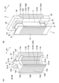
積層鋼板101の積層隙間L1は、カシメ部17,18(図1)の形状によって調整することができる。図9(A)および(B)は、Vカシメであるカシメ部18を模式的に示す平面図および断面図である。カシメ部18は、積層鋼板101のプレス加工により形成される。例えば、積層鋼板101の裏面に形成したV字状の凸部18aを、その下側の積層鋼板101の表面に形成したV字状の凹部18bに嵌合させることで、複数の積層鋼板101を互いに固定する。プレス加工時に凸部18aの突出量すなわち凹部18bの深さ(カシメ深さと称する)Pを調整することにより、積層鋼板101の積層隙間L1を調整することができる。
The laminated gap L1 of the
図10(A)および(B)は、丸カシメであるカシメ部17を模式的に示す平面図および断面図である。カシメ部17は、積層鋼板101のプレス加工により形成される。例えば、積層鋼板101の裏面に形成した円筒状の凸部17aを、その下側の積層鋼板101の表面に形成した円筒状の凹部17bに嵌合させることで、複数の積層鋼板101を互いに固定する。プレス加工時に凸部17aの突出量すなわち凹部17bの深さ(カシメ深さと称する)Pを調整することにより、積層鋼板101の積層隙間L1を調整することができる。
10 (A) and 10 (B) are a plan view and a cross-sectional view schematically showing a caulked
図9および図10には、ステータコア10の積層鋼板101のカシメ部17,18を示したが、ロータコア50の積層鋼板501の積層隙間L0もこれと同様に調整することができる。この実施の形態1では、ステータコア10の積層鋼板101のカシメ深さは、ロータコア50の積層鋼板501のカシメ深さよりも深い。
9 and 10 show the caulked
<作用>
次に、この実施の形態1の電動機100の作用について説明する。図11は、比較例の電動機100Fを示す縦断面図である。説明の便宜上、比較例の電動機100Fの構成要素にも、実施の形態1の電動機100の構成要素と同様の符号を付して説明する。<Action>
Next, the operation of the
比較例の電動機100Fのステータコア10は、板厚T1の積層鋼板101を積層隙間L1で軸方向に積層したものであるが、この積層隙間L1は、ロータコア50の積層鋼板501の積層隙間L0と同じである(L1=L0)。電動機100Fの他の構成は、電動機100と同様である。
The
比較例の電動機100Fのステータコア10は、実施の形態1と同様、第1コア部10Aと第2コア部10Bとを有し、第1コア部10Aの第1ティース部12Aは、第2コア部10Bの第2ティース部12Bよりも幅が狭い(図5参照)。そのため、ロータ5の永久磁石53から出た磁束が第1ティース部12Aに流れ込むと、第1ティース部12Aでは磁束密度が高くなりやすい。
The
第1ティース部12Aで磁束密度が飽和すると、磁束の一部が幅の広い第2ティース部12Bに向かって軸方向に流れる。すなわち、ステータコア10の積層鋼板101の板面に垂直な方向に磁束が流れるため、渦電流が発生する可能性がある。
When the magnetic flux density is saturated in the
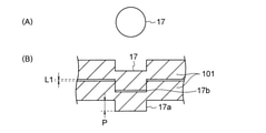
図12は、積層鋼板101における渦電流の発生を説明するための模式図である。積層鋼板101は、板厚T1が0.1~0.7mmと薄いため、矢印F1で示すように積層鋼板101の端面から磁束が侵入しても、渦電流は生じにくい。これに対し、矢印F2で示すように積層鋼板101の板面に垂直に磁束が侵入すると、渦電流が生じやすい。
FIG. 12 is a schematic diagram for explaining the generation of eddy currents in the
そのため、図11に示した比較例のように、ステータコア10内を第1ティース部12Aから第2ティース部12Bに向かって磁束が軸方向に流れると、渦電流損(鉄損)が生じ、モータ効率の低下を招く可能性がある。
Therefore, as in the comparative example shown in FIG. 11, when the magnetic flux flows axially from the
これに対し、この実施の形態1の電動機100は、図8に示したように、ステータコア10を構成する積層鋼板101の積層隙間L1が、ロータコア50を構成する積層鋼板501の積層隙間L0よりも大きい(L0<L1)。
On the other hand, in the
言い換えると、ステータコア10の単位長さ(より具体的には、軸方向における単位長さ)当たりの積層鋼板101の枚数が、ロータコア50の単位長さ当たりの積層鋼板501の枚数よりも少ない。そのため、ステータコア10では、ロータコア50と比較して、軸方向の磁気抵抗が大きく、磁束が軸方向に流れにくい。
In other words, the number of
従って、第1ティース部12Aで磁束密度が飽和すると、磁束の一部は、ロータコア50の磁石挿入孔51よりも外周側の領域を軸方向に流れてから、第2ティース部12Bに侵入する。第2ティース部12Bは幅が広く磁気飽和が生じにくいため、軸方向の磁束の流れは生じにくい。
Therefore, when the magnetic flux density is saturated in the
その結果、ステータコア10内を軸方向に流れる磁束を低減することができ、これにより、図12を参照して説明した渦電流の発生を抑制することができる。すなわち、渦電流損を抑制し、モータ効率を向上することができる。
As a result, the magnetic flux flowing in the
なお、この実施の形態1では、上記の通り、ロータコア50の磁石挿入孔51よりも外周側の領域を磁束が軸方向に流れるが、ロータコア50における永久磁石53の位置は変化しないため、ロータ5の回転に伴うロータコア50内の磁束密度変化が小さい。そのため、ロータコア50の磁石挿入孔51よりも外周側の領域を磁束が軸方向に流れても、これに起因する渦電流損の増加は比較的小さい。
In the first embodiment, as described above, the magnetic flux flows in the axial direction in the region on the outer peripheral side of the
これに対し、ステータコア10では、ロータ5の回転に伴い、ティース12と永久磁石53との位置関係が変化するため、ロータ5の回転に伴うステータコア10内の磁束密度変化が大きい。そのため、ステータコア10内を磁束が軸方向に流れると、これに起因して渦電流損が増加しやすい。そこで、この実施の形態1では、ステータコア10を、ロータコア50よりも磁束が軸方向に流れにくい構成として、渦電流損を低減している。
On the other hand, in the
図13は、ステータコア10の積層鋼板101の積層隙間L1と、ロータコア50の積層鋼板501の積層隙間L0との差(L1-L0)と、モータ効率との関係を示すグラフである。ここでは、積層隙間L0を0.003mmとし、積層隙間L1を変化させた場合のモータ効率の変化を示す。モータ効率は、L1=L0=0.003mmの場合のモータ効率に対する割合で表している。
FIG. 13 is a graph showing the relationship between the difference (L1-L0) between the laminated gap L1 of the
図13から、積層隙間の差L1-L0が0.004~0.012mmの範囲にあるときには、特に高いモータ効率(100.07%以上)が得られていることが分かる。これは、積層隙間の差L1-L0が増加するほど、ステータコア10内を磁束が軸方向に流れにくくなって渦電流損が低減するが、積層隙間L1が大きくなりすぎると、ステータコア10自体の鉄損が増加するためである。そのため、積層隙間の差L1-L0は、0.004~0.012mmの範囲にあることが望ましい。
From FIG. 13, it can be seen that particularly high motor efficiency (100.07% or more) is obtained when the difference L1-L0 of the stacking gap is in the range of 0.004 to 0.012 mm. This is because as the difference L1-L0 in the stacking gap increases, the magnetic flux becomes more difficult to flow in the
<実施の形態の効果>
以上説明したように、実施の形態1では、ステータコア10が、軸方向端部の第1コア部10Aと軸方向中央部の第2コア部10Bとを有し、第1コア部10Aでは第2コア部10Bよりもスロット14の面積が大きい。また、ロータコア50の積層鋼板501の積層隙間L0と、ステータコア10の積層鋼板101の積層隙間L1との間に、L0<L1が成立する。そのため、ステータコア10では、ロータコア50よりも軸方向の磁気抵抗が大きく、磁束が軸方向に流れにくい。これにより、第1コア部10Aの第1ティース部12Aで磁気飽和が生じた場合でも、ステータコア10の積層鋼板101での渦電流の発生を抑制することができる。すなわち、渦電流損を低減し、モータ効率を向上することができる。<Effect of embodiment>
As described above, in the first embodiment, the
また、ステータコア10の第1コア部10Aにおける第1ティース部12Aの周方向の幅が、第2コア部10Bにおける第2ティース部12Bの周方向の幅よりも狭いため、第1ティース部12Aの側方に段差部125を形成することができ、この段差部125にインシュレータ2を嵌合させることができる。
Further, since the width in the circumferential direction of the
また、ステータコア10の積層鋼板101のカシメ深さが、ロータコア50の積層鋼板501のカシメ深さよりも深いため、簡単な構成で、上述した積層隙間L0,L1の関係(L0<L1)を実現することができる。
Further, since the caulking depth of the
また、ステータコア10の積層鋼板101とロータコア50の積層鋼板501との積層隙間の差L1-L0が、0.004mm≦L1-L0≦0.012mmを満足することにより、渦電流損の低減効果を高め、モータ効率をさらに向上することができる。
Further, the difference L1-L0 between the
また、永久磁石53が希土類磁石であり、残留磁束密度が高いため、第1ティース部12Aで磁気飽和が生じやすい。そのため、この実施の形態1による渦電流損の抑制効果が、より有効に発揮される。
Further, since the
また、ロータコア50の磁石挿入孔51は、周方向中央部が径方向内側に突出するようにV字状に形成されているため、磁石挿入孔51よりも外周側の領域を磁束が軸方向に流れやすい。そのため、ステータコア10での渦電流損の低減効果を高めることができる。
Further, since the
また、インシュレータ2が、ステータコア10の第1コア部10Aと第2コア部10Bとの間の段差部125に嵌合するため、インシュレータ2のスロット14側への突出量を小さくすることができる。これにより、スロット14の面積を大きくし、コイル4の巻き数を増加させることができる。その結果、コイル抵抗(すなわち銅損)を低減し、モータ効率をさらに向上することができる。
Further, since the
また、ステータコア10のスロット14の内面に、絶縁フィルム3が設けられているため、スロット14の面積を確保しながら、コイル4とステータコア10とを絶縁することができる。
Further, since the insulating
実施の形態2.
図14は、実施の形態2の電動機100Aを示す縦断面図である。上述した実施の形態1では、ステータコア10の積層鋼板101が一定の積層隙間L1で積層されていた。これに対し、この実施の形態2では、ステータコア10の第1コア部10Aと第2コア部10Bとで、積層鋼板101の積層隙間が異なる。
FIG. 14 is a vertical sectional view showing the
より具体的には、第1コア部10Aの積層鋼板101の積層隙間L1と、第2コア部10Bの積層鋼板101の積層隙間L2と、ロータコア50の積層鋼板501の積層隙間L0とは、L0≦L2<L1の関係を満足する。
More specifically, the laminated gap L1 of the
言い換えると、第1コア部10Aの積層鋼板101のカシメ深さは、第2コア部10Bの積層鋼板101のカシメ深さよりも深く、第2コア部10Bの積層鋼板101のカシメ深さは、ロータコア50の積層鋼板501のカシメ深さ以上である。
In other words, the caulking depth of the
さらに言い換えると、第1コア部10Aの単位長さ当たりの積層鋼板101の枚数は、第2コア部10Bの単位長さ当たりの積層鋼板101の枚数よりも少ない。また、第2コア部10Bの単位長さ当たりの積層鋼板101の枚数は、ロータコア50の単位長さ当たりの積層鋼板501の枚数以下である。
In other words, the number of
そのため、この実施の形態2では、第1コア部10Aにおける軸方向の磁気抵抗が、第2コア部10Bにおける軸方向の磁気抵抗よりも大きく、第2コア部10Bにおける軸方向の磁気抵抗が、ロータコア50における軸方向の磁気抵抗以上である。
Therefore, in the second embodiment, the axial reluctance in the
この実施の形態2では、上述したL0≦L2<L1の関係により、第1コア部10Aで磁束が軸方向に最も流れにくく、ロータコア50の磁石挿入孔51よりも外周側の領域で磁束が軸方向に最も流れやすい。従って、第1ティース部12Aで磁気飽和が生じた場合には、磁束は、ロータコア50の磁石挿入孔51よりも外周側の領域を軸方向に流れる。
In the second embodiment, due to the above-mentioned relationship of L0 ≦ L2 <L1, the magnetic flux is most difficult to flow in the axial direction in the
その結果、実施の形態1と同様に、ステータコア10内を軸方向に流れる磁束を低減し、渦電流の発生を抑制することができる。すなわち、渦電流損(鉄損)を抑制し、モータ効率を向上することができる。
As a result, as in the first embodiment, the magnetic flux flowing in the
なお、ステータコア10の第1コア部10Aの積層鋼板101の積層隙間L1と、ロータコア50の積層鋼板501の積層隙間L0との差(L1-L0)は、実施の形態1と同様、0.004~0.012mmの範囲にあることが望ましい。
The difference (L1-L0) between the laminated gap L1 of the
実施の形態2の電動機100Aの構成は、ステータコア10の構成を除き、実施の形態1の電動機100(図8)と同様である。
The configuration of the
以上説明したように、実施の形態2では、ロータコア50の積層鋼板501の積層隙間L0と、ステータコア10の第1コア部10Aの積層鋼板101の積層隙間L1と、第2コア部10Bの積層鋼板101の積層隙間L2とが、L0≦L2<L1の関係を満足するため、第1コア部10Aでは磁束が軸方向に最も流れにくく、ロータコア50の磁石挿入孔51よりも外周側の領域では磁束が軸方向に最も流れやすい。従って、ステータコア10内の軸方向の磁束の流れを低減し、これにより渦電流損を低減し、モータ効率を向上することができる。
As described above, in the second embodiment, the laminated gap L0 of the
実施の形態3.
図15は、実施の形態3の電動機100Bを示す縦断面図である。上述した実施の形態1では、ステータコア10の積層鋼板101の板厚T1と、ロータコア50の積層鋼板501の板厚T0とが同じであった。これに対し、この実施の形態3では、ステータコア10とロータコア50とで、積層鋼板101,501の板厚が異なる。
FIG. 15 is a vertical sectional view showing the
より具体的には、ロータコア50の積層鋼板501の板厚T0は、ステータコア10の積層鋼板101の板厚T1よりも厚い。言い換えると、ロータコア50の積層鋼板501の板厚T0と、ステータコア10の積層鋼板101の板厚T1とは、T0>T1の関係を満足する。
More specifically, the plate thickness T0 of the
ロータコア50の積層鋼板501の板厚T0は、例えば0.35mmであり、ステータコア10の積層鋼板101の板厚T1は、例えば0.25mmである。
The plate thickness T0 of the
なお、ステータコア10の積層鋼板101の積層隙間L1と、ロータコア50の積層鋼板501の積層隙間L0とは、ここでは同じ(L0=L1)である。
The laminated gap L1 of the
積層鋼板の板厚が薄いほど、単位長さ当たりの積層枚数が多くなる。そのため、積層鋼板101,501の積層隙間L0,L1が同じであっても、積層鋼板101の単位長さ当たりの積層隙間L1の合計は、積層鋼板501の単位長さ当たりの積層隙間L0の合計よりも大きくなる。
The thinner the laminated steel sheet, the larger the number of laminated steel sheets per unit length. Therefore, even if the laminated gaps L0 and L1 of the
そのため、ステータコア10では、ロータコア50と比較して、軸方向の磁気抵抗が大きく、磁束が軸方向に流れにくい。従って、第1ティース部12Aで磁束密度が飽和すると、磁束はロータコア50内を軸方向に流れる。
Therefore, in the
その結果、実施の形態1と同様に、ステータコア10内を軸方向に流れる磁束を低減し、渦電流の発生を抑制することができる。すなわち、渦電流損を抑制し、モータ効率を向上することができる。
As a result, as in the first embodiment, the magnetic flux flowing in the
図16は、ロータコア50の積層鋼板501の板厚T0とステータコア10の積層鋼板101の板厚T1との差(T0-T1)と、モータ効率との関係を示すグラフである。ここでは、板厚T0を0.35mmとし、板厚T1を変化させた場合のモータ効率の変化を示している。また、モータ効率は、T0=T1=0.35mmの場合のモータ効率に対する割合で表している。
FIG. 16 is a graph showing the relationship between the difference (T0-T1) between the plate thickness T0 of the
図16から、板厚の差T0-T1が0.05mm~0.15mmの範囲にあるときには、特に高いモータ効率(100.10%以上)が得られていることが分かる。これは、板厚の差T0-T1が増加するほど、ステータコア10内を磁束が軸方向に流れにくくなって渦電流損が低減するが、板厚T1が薄くなりすぎると、ステータコア10のヒステリシス損が増加するためである。そのため、板厚の差T0-T1は、0.05mm~0.15mmの範囲にあることが望ましい。
From FIG. 16, it can be seen that particularly high motor efficiency (100.10% or more) is obtained when the difference in plate thickness T0-T1 is in the range of 0.05 mm to 0.15 mm. This is because as the difference in plate thickness T0-T1 increases, the magnetic flux does not easily flow in the
なお、実施の形態3の電動機100Bの構成は、ステータコア10の構成を除き、実施の形態1の電動機100(図8)と同様である。
The configuration of the
以上説明したように、実施の形態3では、ロータコア50の積層鋼板501の板厚T0と、ステータコア10の積層鋼板101の板厚T1との間に、T0>T1が成立する。そのため、ステータコア10では、ロータコア50と比較して磁束が軸方向に流れにくい。これにより、ステータコア10の積層鋼板101における渦電流の発生を抑制することができる。すなわち、渦電流損を低減し、モータ効率を向上することができる。
As described above, in the third embodiment, T0> T1 is established between the plate thickness T0 of the
また、ロータコア50の積層鋼板501とステータコア10の積層鋼板101との板厚の差T0-T1が、0.05mm≦T0-T1≦0.15mmを満足することで、渦電流損の低減効果を高め、モータ効率をさらに向上することができる。
Further, the difference in plate thickness T0-T1 between the
なお、ステータコア10の積層鋼板101の積層隙間L1と、ロータコア50の積層鋼板501の積層隙間L0とは、ここでは同じ(L0=L1)であるが、実施の形態1のように、L0<L1を満足するようにしてもよい。この場合、積層隙間の差(L1-L0)は、0.004~0.012mmの範囲にあることが望ましい。
The laminated gap L1 of the
また、実施の形態2のように、第1コア部10Aの積層鋼板101の積層隙間L1と、第2コア部10Bの積層鋼板101の積層隙間L2と、ロータコア50の積層鋼板501の積層隙間L0とが、L0≦L2<L1の関係を満足するようにしてもよい。
Further, as in the second embodiment, the laminated gap L1 of the
実施の形態4.
図17は、実施の形態4の電動機100Cを示す縦断面図である。上述した実施の形態3では、ステータコア10の積層鋼板101の板厚T1が一定であった。これに対し、この実施の形態4では、ステータコア10の第1コア部10Aと第2コア部10Bとで、積層鋼板101の板厚が異なる。
FIG. 17 is a vertical sectional view showing the
より具体的には、ロータコア50の積層鋼板501の板厚T0と、第1コア部10Aの積層鋼板101の板厚T1と、第2コア部10Bの積層鋼板101の板厚T2とは、T0≧T2>T1の関係を満足する。
More specifically, the plate thickness T0 of the
言い換えると、第1コア部10Aの単位長さ当たりの積層鋼板101の枚数は、第2コア部10Bの単位長さ当たりの積層鋼板101の枚数よりも少ない。また、第2コア部10Bの単位長さ当たりの積層鋼板101の枚数は、ロータコア50の単位長さ当たりの積層鋼板501の枚数以下である。
In other words, the number of
そのため、この実施の形態4では、第1コア部10Aにおける軸方向の磁気抵抗が、第2コア部10Bにおける軸方向の磁気抵抗よりも大きく、また、第2コア部10Bにおける軸方向の磁気抵抗が、ロータコア50における軸方向の磁気抵抗以上である。
Therefore, in the fourth embodiment, the axial reluctance in the
この実施の形態4では、上述したT0≧T2>T1の関係により、第1コア部10Aで磁束が軸方向に最も流れにくく、ロータコア50の磁石挿入孔51よりも外周側の領域で磁束が軸方向に最も流れやすい。従って、第1ティース部12Aで磁気飽和が生じた場合には、磁束は、ロータコア50の磁石挿入孔51よりも外周側の領域を軸方向に流れる。
In the fourth embodiment, due to the above-mentioned relationship of T0 ≧ T2> T1, the magnetic flux is most difficult to flow in the axial direction in the
その結果、実施の形態1と同様に、ステータコア10内を軸方向に流れる磁束を低減し、渦電流の発生を抑制することができる。すなわち、渦電流損を抑制し、モータ効率を向上することができる。
As a result, as in the first embodiment, the magnetic flux flowing in the
なお、実施の形態4の電動機100Cの構成は、ステータコア10の構成を除き、実施の形態1の電動機100(図8)と同様である。
The configuration of the
以上説明したように、実施の形態4では、ロータコア50の積層鋼板501の板厚T0と、ステータコア10の第1コア部10Aの積層鋼板101の板厚T1と、第2コア部10Bの積層鋼板101の板厚T2とが、T0≧T2>T1の関係を満足するため、第1コア部10Aでは磁束が軸方向に最も流れにくく、ロータコア50の磁石挿入孔51よりも外周側の領域では磁束が軸方向に最も流れやすい。従って、ステータコア10内の軸方向の磁束の流れを低減し、これにより渦電流損を低減し、モータ効率を向上することができる。
As described above, in the fourth embodiment, the thickness T0 of the
なお、ステータコア10の積層鋼板101の積層隙間L1と、ロータコア50の積層鋼板501の積層隙間L0とは、ここでは同じ(L0=L1)であるが、実施の形態1のように、L0<L1を満足するようにしてもよい。この場合、積層隙間の差(L1-L0)は、0.004~0.012mmの範囲にあることが望ましい。
The laminated gap L1 of the
また、実施の形態2のように、第1コア部10Aの積層鋼板101の積層隙間L1と、第2コア部10Bの積層鋼板101の積層隙間L2と、ロータコア50の積層鋼板501の積層隙間L0とが、L0≦L2<L1の関係を満足するようにしてもよい。
Further, as in the second embodiment, the laminated gap L1 of the
実施の形態5.
図18は、実施の形態5の電動機100Dを示す縦断面図である。上述した実施の形態1~4では、ロータコア50の軸方向長さとステータコア10の軸方向長さとが、互いに同じであった。これに対し、この実施の形態5では、ロータコア50の軸方向長さHrが、ステータコア10の軸方向長さHsよりも長い。
FIG. 18 is a vertical sectional view showing the
図18に示すように、ロータコア50の軸方向両端部は、ステータコア10から軸方向に突出している。ロータコア50の軸方向長さHrは、例えば50mmであり、ステータコア10の軸方向長さHsは、例えば45mmである。
As shown in FIG. 18, both ends in the axial direction of the
他の構成は、実施の形態4で説明した通りである。すなわち、ロータコア50の積層鋼板501の板厚T0と、第1コア部10Aの積層鋼板101の板厚T1と、第2コア部10Bの積層鋼板101の板厚T2とが、T0≧T2>T1の関係を満足する。
Other configurations are as described in
この実施の形態5では、ロータコア50の軸方向長さHrが、ステータコア10の軸方向長さHsよりも長い。そのため、コイル4の線長を長くすることなく、コイル4に鎖交する永久磁石53の磁束を増加させることができる。すなわち、コイル抵抗を小さくし、モータ効率をさらに向上することができる。
In the fifth embodiment, the axial length Hr of the
一方、ロータコア50の軸方向長さHrがステータコア10の軸方向長さHsよりも長いため、ステータコア10の軸方向両端部(すなわち第1コア部10A)での磁束密度が高くなり、その結果、ロータコア50から第1ティース部12Aに流れる磁束が増加する。そのため、第1ティース部12Aでの磁気飽和によって軸方向の磁束流れが生じやすく、上述した渦電流損が特に発生しやすい。
On the other hand, since the axial length Hr of the
この実施の形態5では、上述したT0≧T2>T1の関係により、ステータコア10での渦電流損の発生を抑制しているが、ロータコア50の軸方向長さHrがステータコア10の軸方向長さHsよりも長い電動機10Dでは、この渦電流損の抑制効果が、特に有効に発揮される。
In the fifth embodiment, the occurrence of eddy current loss in the
以上説明したように、実施の形態5では、ロータコア50の軸方向長さHrがステータコア10の軸方向長さHsよりも長いため、上述したT0≧T2>T1の関係による渦電流損の低減効果(すなわちモータ効率の向上効果)が特に有効に発揮される。
As described above, in the fifth embodiment, since the axial length Hr of the
なお、この実施の形態5では、上述した実施の形態4で説明した電動機において、ロータコア50の軸方向長さHrがステータコア10の軸方向長さHsよりも長い構成を採用した。しかしながら、実施の形態1~3で説明した電動機において、ロータコア50の軸方向長さHrがステータコア10の軸方向長さHsよりも長い構成を採用してもよい。
In the fifth embodiment, in the motor described in the fourth embodiment described above, a configuration in which the axial length Hr of the
図19は、実施の形態1で説明した電動機100(図8)において、ロータコア50の軸方向長さHrがステータコア10の軸方向長さHsよりも長い構成を採用した電動機100Eを示す縦断面図である。図19に示すように、ロータコア50の軸方向両端は、ステータコア10から軸方向に突出している。
FIG. 19 is a vertical cross-sectional view showing an
ステータコア10およびロータコア50は、軸方向長さが異なることを除き、実施の形態1と同様に構成されている。すなわち、ステータコア10の積層鋼板101の積層隙間L1は、ロータコア50の積層鋼板501の積層隙間L0よりも広い(L0<L1)。
The
上述したL0<L1の関係により、ステータコア10での渦電流損の発生を抑制することができるが、ロータコア50の軸方向長さHrがステータコア10の軸方向長さHsよりも長い電動機10Eでは、この渦電流損の抑制効果が特に有効に発揮される。
Due to the above-mentioned relationship of L0 <L1, the occurrence of eddy current loss in the
また、実施の形態2および3で説明した電動機に、ロータコア50の軸方向長さHrがステータコア10の軸方向長さHsよりも長い構成を採用した場合も、渦電流損の抑制効果が特に有効に発揮される。
Further, even when the motors described in the second and third embodiments have a configuration in which the axial length Hr of the
<ロータリ圧縮機>
次に、上述した各実施の形態の電動機が適用可能なロータリ圧縮機300について説明する。図20は、ロータリ圧縮機300を示す断面図である。ロータリ圧縮機300は、フレーム301と、フレーム301内に配設された圧縮機構310と、圧縮機構310を駆動する電動機100とを備える。<Rotary compressor>
Next, the
圧縮機構310は、シリンダ室312を有するシリンダ311と、電動機100のシャフト58に固定されたローリングピストン314と、シリンダ室312内を吸入側と圧縮側に分けるベーン(図示せず)と、シャフト58が挿入されてシリンダ室312の軸方向端面を閉鎖する上部フレーム316および下部フレーム317とを有する。上部フレーム316および下部フレーム317には、上部吐出マフラ318および下部吐出マフラ319がそれぞれ装着されている。
The
フレーム301は、例えば厚さ3mmの鋼板を絞り加工して形成された円筒形状の容器である。フレーム301の底部には、圧縮機構310の各摺動部を潤滑する冷凍機油(図示せず)が貯留されている。シャフト58は、上部フレーム316および下部フレーム317によって回転可能に保持されている。
The
シリンダ311は、内部にシリンダ室312を備えている。ローリングピストン314は、シリンダ室312内で偏心回転する。シャフト58は偏心軸部を有しており、その偏心軸部にローリングピストン314が嵌合している。
The
電動機100のステータコア10は、焼き嵌めによりフレーム301の内側に取り付けられている。ステータコア10に巻回されたコイル4には、フレーム301に固定されたガラス端子305から電力が供給される。ロータ5のシャフト孔55(図1)には、シャフト58が固定されている。
The
フレーム301の外部には、冷媒ガスを貯蔵するアキュムレータ302が取り付けられている。フレーム301には吸入パイプ303が固定され、この吸入パイプ303を介してアキュムレータ302からシリンダ311に冷媒ガスが供給される。また、フレーム301の上部には、冷媒を外部に吐出する吐出パイプ307が設けられている。
An
冷媒としては、例えば、R410A、R407CまたはR22等を用いることができる。また、地球温暖化防止の観点からは、低GWP(地球温暖化係数)の冷媒を用いることが望ましい。低GWPの冷媒としては、例えば、以下の冷媒を用いることができる。 As the refrigerant, for example, R410A, R407C, R22 or the like can be used. From the viewpoint of preventing global warming, it is desirable to use a refrigerant having a low GWP (global warming potential). As the low GWP refrigerant, for example, the following refrigerants can be used.
(1)まず、組成中に炭素の二重結合を有するハロゲン化炭化水素、例えばHFO(Hydro-Fluoro-Orefin)-1234yf(CF3CF=CH2)を用いることができる。HFO-1234yfのGWPは4である。
(2)また、組成中に炭素の二重結合を有する炭化水素、例えばR1270(プロピレン)を用いてもよい。R1270のGWPは3であり、HFO-1234yfより低いが、可燃性はHFO-1234yfより高い。
(3)また、組成中に炭素の二重結合を有するハロゲン化炭化水素または組成中に炭素の二重結合を有する炭化水素の少なくともいずれかを含む混合物、例えばHFO-1234yfとR32との混合物を用いてもよい。上述したHFO-1234yfは低圧冷媒のため圧損が大きくなる傾向があり、冷凍サイクル(特に蒸発器)の性能低下を招く可能性がある。そのため、HFO-1234yfよりも高圧冷媒であるR32またはR41との混合物を用いることが実用上は望ましい。(1) First, a halogenated hydrocarbon having a carbon double bond in the composition, for example, HFO (Hydro-Fluoro-Orefin) -1234yf (CF 3 CF = CH 2 ) can be used. The GWP of HFO-1234yf is 4.
(2) Further, a hydrocarbon having a carbon double bond in the composition, for example, R1270 (propylene) may be used. The GWP of R1270 is 3, which is lower than HFO-1234yf, but more flammable than HFO-1234yf.
(3) Also, a mixture containing at least one of a halogenated hydrocarbon having a carbon double bond in the composition or a hydrocarbon having a carbon double bond in the composition, for example, a mixture of HFO-1234yf and R32. You may use it. Since the above-mentioned HFO-1234yf is a low-pressure refrigerant, the pressure loss tends to be large, which may lead to deterioration of the performance of the refrigeration cycle (particularly the evaporator). Therefore, it is practically desirable to use a mixture with R32 or R41, which is a high-pressure refrigerant, rather than HFO-1234yf.
ロータリ圧縮機300の動作は、以下の通りである。アキュムレータ302から供給された冷媒ガスは、吸入パイプ303を通ってシリンダ311のシリンダ室312内に供給される。電動機100が駆動されてロータ5が回転すると、ロータ5と共にシャフト58が回転する。そして、シャフト58に嵌合するローリングピストン314がシリンダ室312内で偏心回転し、シリンダ室312内で冷媒が圧縮される。圧縮された冷媒は、吐出マフラ318,319を通り、さらに電動機100に設けられた穴(図示せず)を通ってフレーム301内を上昇し、吐出パイプ307から吐出される。
The operation of the
上述した各実施の形態で説明した電動機は、渦電流の抑制により高いモータ効率を有する。そのため、圧縮機300の駆動源に各実施の形態で説明した電動機を用いることで、圧縮機300の運転効率を向上することができる。
The motor described in each of the above-described embodiments has high motor efficiency due to the suppression of eddy current. Therefore, by using the electric motor described in each embodiment as the drive source of the
<空気調和装置>
次に、図20に示した圧縮機300を備えた空気調和装置400について説明する。図21は、空気調和装置400を示す図である。図21に示した空気調和装置400は、圧縮機401と、凝縮器402と、絞り装置(減圧装置)403と、蒸発器404とを備える。圧縮機401、凝縮器402、絞り装置403および蒸発器404は、冷媒配管407によって連結され、冷凍サイクルを構成している。すなわち、圧縮機401、凝縮器402、絞り装置403および蒸発器404の順に、冷媒が循環する。<Air conditioner>
Next, the
圧縮機401、凝縮器402および絞り装置403は、室外機410に設けられている。圧縮機401は、図20に示したロータリ圧縮機300で構成されている。室外機410には、凝縮器402に室外の空気を供給する室外側送風機405が設けられている。蒸発器404は、室内機420に設けられている。この室内機420には、蒸発器404に室内の空気を供給する室内側送風機406が設けられている。
The
空気調和装置400の動作は、次の通りである。圧縮機401は、吸入した冷媒を圧縮して送り出す。凝縮器402は、圧縮機401から流入した冷媒と室外の空気との熱交換を行い、冷媒を凝縮して液化させて冷媒配管407に送り出す。室外側送風機405は、凝縮器402に室外の空気を供給する。絞り装置403は、開度を変化させることによって、冷媒配管407を流れる冷媒の圧力等を調整する。
The operation of the
蒸発器404は、絞り装置403により低圧状態にされた冷媒と室内の空気との熱交換を行い、冷媒に空気の熱を奪わせて蒸発(気化)させて、冷媒配管407に送り出す。室内側送風機406は、蒸発器404に室内の空気を供給する。これにより、蒸発器404で熱が奪われた冷風が、室内に供給される。
The
空気調和装置400は、各実施の形態で説明した電動機の適用により運転効率を向上した圧縮機401を用いている。そのため、空気調和装置400の運転効率を向上することができる。
The
以上、本発明の望ましい実施の形態について具体的に説明したが、本発明は上記の実施の形態に限定されるものではなく、本発明の要旨を逸脱しない範囲において、各種の改良または変形を行なうことができる。 Although the preferred embodiment of the present invention has been specifically described above, the present invention is not limited to the above-described embodiment, and various improvements or modifications are made without departing from the gist of the present invention. be able to.
1 ステータ、 2 インシュレータ、 3 絶縁フィルム、 4 コイル、 5 ロータ、 9,9A,9B 分割コア、 10 ステータコア、 10A 第1コア部、 10B 第2コア部、 11 ヨーク、 11A 第1ヨーク部、 11B 第2ヨーク部、 12 ティース、 12A 第1ティース部、 12B 第2ティース部、 13 歯先部、 13A 第1歯先部、 13B 第2歯先部、 14 スロット、 16 穴、 17,18 カシメ部、 20 胴部、 21 フランジ部、 25 壁部、 26 突起、 50 ロータコア、 51 磁石挿入孔、 52 フラックスバリア、 53 永久磁石、 55 シャフト孔、 58 シャフト、 100,100A,100B,100C,100D,100E 電動機、 101 積層鋼板、 111A,111B 内周面、 121A,121B 側面、 125 段差部、 131A,131B 外周面、 300 ロータリ圧縮機(圧縮機)、 301 フレーム、 310 圧縮機構、 400 空気調和装置、 401 圧縮機、 402 凝縮器、 403 絞り装置、 404 蒸発器、 405 室外側送風機、 406 室内側送風機、 407 冷媒配管、 410 室外機、 420 室内機、 501 積層鋼板。
1 Refrigerant, 2 Insulator, 3 Insulation film, 4 Coil, 5 Rotor, 9, 9A, 9B split core, 10 Stator core, 10A 1st core part, 10B 2nd core part, 11 yoke, 11A 1st yoke part,
Claims (13)
前記ロータを囲むように設けられたステータであって、積層鋼板を前記軸方向に積層したステータコアと、前記ステータコアに巻き付けられたコイルとを有するステータと
を有し、
前記ステータコアは、前記コイルを収容するスロットを有し、
前記ステータコアは、前記軸方向の端部に位置する第1コア部と、前記軸方向の中央部に位置する第2コア部とを有し、
前記第1コア部における前記スロットの面積は、前記第2コア部における前記スロットの面積よりも大きく、
前記ロータコアの前記積層鋼板の積層隙間L0と、前記ステータコアの前記第1コア部における前記積層鋼板の積層隙間L1との間に、L0<L1が成立し、
前記ステータコアの前記第1コア部における前記積層鋼板のカシメ深さが、前記ロータコアの前記積層鋼板のカシメ深さよりも深い電動機。 A rotor that is rotatable about a rotation axis and has a rotor core in which laminated steel plates are laminated in the axial direction of the rotation axis, and a rotor having a permanent magnet embedded in the rotor core.
A stator provided so as to surround the rotor, the stator having a stator core in which laminated steel plates are laminated in the axial direction, and a coil wound around the stator core.
Have,
The stator core has a slot for accommodating the coil.
The stator core has a first core portion located at an end portion in the axial direction and a second core portion located at a central portion in the axial direction.
The area of the slot in the first core portion is larger than the area of the slot in the second core portion.
L0 <L1 is established between the laminated gap L0 of the laminated steel plate of the rotor core and the laminated gap L1 of the laminated steel plate in the first core portion of the stator core.
An electric motor in which the caulking depth of the laminated steel plate in the first core portion of the stator core is deeper than the caulking depth of the laminated steel plate of the rotor core.
前記ロータを囲むように設けられたステータであって、積層鋼板を前記軸方向に積層したステータコアと、前記ステータコアに巻き付けられたコイルとを有するステータと
を有し、
前記ステータコアは、前記コイルを収容するスロットを有し、
前記ステータコアは、前記軸方向の端部に位置する第1コア部と、前記軸方向の中央部に位置する第2コア部とを有し、
前記第1コア部における前記スロットの面積は、前記第2コア部における前記スロットの面積よりも大きく、
前記ロータコアの前記積層鋼板の積層隙間L0と、
前記ステータコアの前記第1コア部における前記積層鋼板の積層隙間L1と、
前記ステータコアの前記第2コア部における前記積層鋼板の積層隙間L2とが、
L0≦L2<L1
を満足する電動機。 A rotor that is rotatable about a rotation axis and has a rotor core in which laminated steel plates are laminated in the axial direction of the rotation axis, and a rotor having a permanent magnet embedded in the rotor core.
A stator provided so as to surround the rotor, the stator having a stator core in which laminated steel plates are laminated in the axial direction, and a coil wound around the stator core.
Have,
The stator core has a slot for accommodating the coil.
The stator core has a first core portion located at an end portion in the axial direction and a second core portion located at a central portion in the axial direction.
The area of the slot in the first core portion is larger than the area of the slot in the second core portion.
Laminating gap L0 of the laminated steel plate of the rotor core and
The laminated gap L1 of the laminated steel sheet in the first core portion of the stator core,
The laminated gap L2 of the laminated steel sheet in the second core portion of the stator core is
L0≤L2 <L1
Satisfy the motor.
前記ロータを囲むように設けられたステータであって、積層鋼板を前記軸方向に積層したステータコアと、前記ステータコアに巻き付けられたコイルとを有するステータと
を有し、
前記ステータコアは、前記コイルを収容するスロットを有し、
前記ステータコアは、前記軸方向の端部に位置する第1コア部と、前記軸方向の中央部に位置する第2コア部とを有し、
前記第1コア部における前記スロットの面積は、前記第2コア部における前記スロットの面積よりも大きく、
前記ステータコアの前記第1コア部における前記積層鋼板の積層隙間L1と、前記ロータコアの前記積層鋼板の積層隙間L0との差L1-L0が、
0.004mm≦L1-L0≦0.012mm
を満足する電動機。 A rotor that is rotatable about a rotation axis and has a rotor core in which laminated steel plates are laminated in the axial direction of the rotation axis, and a rotor having a permanent magnet embedded in the rotor core.
A stator provided so as to surround the rotor, the stator having a stator core in which laminated steel plates are laminated in the axial direction, and a coil wound around the stator core.
Have,
The stator core has a slot for accommodating the coil.
The stator core has a first core portion located at an end portion in the axial direction and a second core portion located at a central portion in the axial direction.
The area of the slot in the first core portion is larger than the area of the slot in the second core portion.
The difference L1-L0 between the laminated gap L1 of the laminated steel plate in the first core portion of the stator core and the laminated gap L0 of the laminated steel plate of the rotor core is
0.004 mm ≤ L1-L0 ≤ 0.012 mm
Satisfy the motor.
前記ステータコアの前記第1コア部における前記ティースの前記周方向の幅は、前記第2コア部における前記ティースの前記周方向の幅よりも狭い
請求項1に記載の電動機。 The stator core has a yoke extending in the circumferential direction about the rotation axis and teeth extending from the yoke toward the rotation axis.
The motor according to claim 1, wherein the width of the teeth in the first core portion of the stator core in the circumferential direction is narrower than the width of the teeth in the circumferential direction in the second core portion.
前記ステータコアの前記第1コア部における前記積層鋼板の板厚T1と、
前記ステータコアの前記第2コア部における前記積層鋼板の板厚T2とが、
T0≧T2>T1
を満足する請求項1から4までの何れか1項に記載の電動機。 The thickness T0 of the laminated steel plate of the rotor core and
The plate thickness T1 of the laminated steel plate in the first core portion of the stator core and
The plate thickness T2 of the laminated steel plate in the second core portion of the stator core is
T0 ≧ T2> T1
The motor according to any one of claims 1 to 4 .
請求項1から5までの何れか1項に記載の電動機。 The electric motor according to any one of claims 1 to 5.
請求項1から7までの何れか1項に記載の電動機。 The electric motor according to any one of claims 1 to 7, wherein the permanent magnet is a rare earth magnet.
前記磁石挿入孔は、前記回転軸を中心とする周方向の中央部が前記回転軸に向けて突出するように、V字状に形成されている
請求項1から8までの何れか1項に記載の電動機。 The rotor core has a magnet insertion hole for inserting the permanent magnet.
The magnet insertion hole is formed in a V shape so that the central portion in the circumferential direction about the rotation axis projects toward the rotation axis, according to any one of claims 1 to 8. The motor described.
前記インシュレータは、前記ステータコアの前記第1コア部と前記第2コア部との間に形成される段差部に嵌合している
請求項1から9までの何れか1項に記載の電動機。 Further provided with an insulator disposed between the stator core and the coil.
The motor according to any one of claims 1 to 9, wherein the insulator is fitted in a step portion formed between the first core portion and the second core portion of the stator core.
前記ステータコアの前記スロットの内面には、絶縁フィルムが配置されている
請求項10に記載の電動機。 The insulator is arranged in the first core portion of the stator core, and is arranged.
The motor according to claim 10, wherein an insulating film is arranged on the inner surface of the slot of the stator core.
前記圧縮機は、請求項1から11までの何れか1項に記載の電動機と、前記電動機によって駆動される圧縮機構とを備えた
空気調和装置。 Equipped with compressor, condenser, decompressor and evaporator,
The compressor is an air conditioner including the motor according to any one of claims 1 to 11 and a compression mechanism driven by the motor.
Applications Claiming Priority (1)
| Application Number | Priority Date | Filing Date | Title |
|---|---|---|---|
| PCT/JP2018/028170 WO2020021692A1 (en) | 2018-07-27 | 2018-07-27 | Electric motor, compressor, and air conditioner |
Publications (2)
| Publication Number | Publication Date |
|---|---|
| JPWO2020021692A1 JPWO2020021692A1 (en) | 2021-01-07 |
| JP7003267B2 true JP7003267B2 (en) | 2022-01-20 |
Family
ID=69181485
Family Applications (1)
| Application Number | Title | Priority Date | Filing Date |
|---|---|---|---|
| JP2020532101A Active JP7003267B2 (en) | 2018-07-27 | 2018-07-27 | Motors, compressors and air conditioners |
Country Status (6)
| Country | Link |
|---|---|
| US (1) | US11804739B2 (en) |
| EP (1) | EP3832849A4 (en) |
| JP (1) | JP7003267B2 (en) |
| KR (1) | KR102549047B1 (en) |
| CN (1) | CN112425033B (en) |
| WO (1) | WO2020021692A1 (en) |
Families Citing this family (5)
| Publication number | Priority date | Publication date | Assignee | Title |
|---|---|---|---|---|
| CN216356176U (en) * | 2019-05-29 | 2022-04-19 | 三菱电机株式会社 | Motor and compressor provided with same |
| EP4134600A4 (en) * | 2020-04-09 | 2023-05-31 | Mitsubishi Electric Corporation | Refrigeration cycle device and air-conditioning device |
| CN116670395A (en) * | 2020-11-30 | 2023-08-29 | 三菱电机株式会社 | Compressor, refrigeration cycle device, and air conditioner |
| JPWO2022259453A1 (en) * | 2021-06-10 | 2022-12-15 | ||
| CN117879195A (en) * | 2022-10-11 | 2024-04-12 | 株式会社电装 | Rotary electric machine |
Citations (3)
| Publication number | Priority date | Publication date | Assignee | Title |
|---|---|---|---|---|
| JP2009284756A (en) | 2008-04-25 | 2009-12-03 | Hitachi Ltd | Rotating electric machine |
| JP2017103850A (en) | 2015-11-30 | 2017-06-08 | 三菱電機株式会社 | Rotary electric machine |
| WO2018016026A1 (en) | 2016-07-20 | 2018-01-25 | 三菱電機株式会社 | Motor and air conditioner |
Family Cites Families (9)
| Publication number | Priority date | Publication date | Assignee | Title |
|---|---|---|---|---|
| WO2003065544A1 (en) * | 2002-01-30 | 2003-08-07 | Mitsubishi Denki Kabushiki Kaisha | Stator of rotating electric motor |
| JP2010045870A (en) * | 2008-08-08 | 2010-02-25 | Fuji Electric Systems Co Ltd | Rotating machine |
| JP5623498B2 (en) * | 2012-12-28 | 2014-11-12 | 三菱電機株式会社 | Stator core and stator, electric motor and compressor |
| JP6132156B2 (en) * | 2013-09-13 | 2017-05-24 | 株式会社デンソー | Rotating electric machine |
| JP6469954B2 (en) | 2014-03-07 | 2019-02-13 | オリエンタルモーター株式会社 | Hybrid stepping motor |
| JP2017017784A (en) | 2015-06-29 | 2017-01-19 | 三菱電機株式会社 | Magnetic pole, stator with magnetic pole, and rotary electric machine with stator |
| KR102051823B1 (en) | 2015-10-30 | 2019-12-04 | 미쓰비시덴키 가부시키가이샤 | Electric motors, rotors, compressors and refrigeration air conditioning units |
| JP6436065B2 (en) | 2015-11-18 | 2018-12-12 | トヨタ自動車株式会社 | Rotating electric machine |
| EP3982515B1 (en) * | 2018-03-12 | 2023-05-03 | Mitsubishi Electric Corporation | Electric motor, compressor, fan, and refrigerating and air conditioning apparatus |
-
2018
- 2018-07-27 US US17/251,048 patent/US11804739B2/en active Active
- 2018-07-27 WO PCT/JP2018/028170 patent/WO2020021692A1/en unknown
- 2018-07-27 EP EP18927889.8A patent/EP3832849A4/en active Pending
- 2018-07-27 CN CN201880095616.8A patent/CN112425033B/en active Active
- 2018-07-27 KR KR1020217001779A patent/KR102549047B1/en active IP Right Grant
- 2018-07-27 JP JP2020532101A patent/JP7003267B2/en active Active
Patent Citations (3)
| Publication number | Priority date | Publication date | Assignee | Title |
|---|---|---|---|---|
| JP2009284756A (en) | 2008-04-25 | 2009-12-03 | Hitachi Ltd | Rotating electric machine |
| JP2017103850A (en) | 2015-11-30 | 2017-06-08 | 三菱電機株式会社 | Rotary electric machine |
| WO2018016026A1 (en) | 2016-07-20 | 2018-01-25 | 三菱電機株式会社 | Motor and air conditioner |
Also Published As
| Publication number | Publication date |
|---|---|
| WO2020021692A1 (en) | 2020-01-30 |
| CN112425033A (en) | 2021-02-26 |
| KR102549047B1 (en) | 2023-06-28 |
| EP3832849A4 (en) | 2021-08-25 |
| EP3832849A1 (en) | 2021-06-09 |
| KR20210021070A (en) | 2021-02-24 |
| US20210203196A1 (en) | 2021-07-01 |
| US11804739B2 (en) | 2023-10-31 |
| CN112425033B (en) | 2024-04-02 |
| JPWO2020021692A1 (en) | 2021-01-07 |
Similar Documents
| Publication | Publication Date | Title |
|---|---|---|
| JP7003267B2 (en) | Motors, compressors and air conditioners | |
| US10483816B2 (en) | Motor, rotor, compressor, and refrigeration and air conditioning apparatus | |
| US10020699B2 (en) | Embedded permanent magnet type electric motor, compressor, and refrigeration air-conditioning device | |
| US9634531B2 (en) | Electric motor with embedded permanent magnet, compressor, and refrigeration/air-conditioning device | |
| JP6824333B2 (en) | Electric motors, rotors, compressors and refrigeration and air conditioners | |
| WO2015093598A1 (en) | Permanent magnet-embedded electrical motor, compressor, and refrigerating air conditioning device | |
| JP7237178B2 (en) | Rotors, electric motors, compressors, and air conditioners | |
| JP7105999B2 (en) | Electric motor, compressor, air conditioner, and method for manufacturing electric motor | |
| JP7038827B2 (en) | Stator, motor, compressor and air conditioner | |
| JP6956881B2 (en) | Motors, compressors, and air conditioners | |
| JP7433420B2 (en) | Rotors, motors, compressors and air conditioners | |
| JP7204897B2 (en) | Rotors, motors, compressors, and air conditioners | |
| JP7450805B2 (en) | Motors, compressors and refrigeration cycle equipment | |
| JP7154373B2 (en) | Electric motors, compressors, and air conditioners | |
| WO2023233629A1 (en) | Stator, electric motor, compressor, and refrigeration cycle device | |
| JP7026811B2 (en) | Stator, motor, compressor and air conditioner | |
| JP7285961B2 (en) | Stators, electric motors, compressors and air conditioners | |
| WO2015198444A1 (en) | Interior permanent magnet electric motor, compressor, and refrigerating and air-conditioning device |
Legal Events
| Date | Code | Title | Description |
|---|---|---|---|
| A521 | Request for written amendment filed |
Free format text: JAPANESE INTERMEDIATE CODE: A523 Effective date: 20200716 |
|
| A621 | Written request for application examination |
Free format text: JAPANESE INTERMEDIATE CODE: A621 Effective date: 20200716 |
|
| A131 | Notification of reasons for refusal |
Free format text: JAPANESE INTERMEDIATE CODE: A131 Effective date: 20210706 |
|
| A521 | Request for written amendment filed |
Free format text: JAPANESE INTERMEDIATE CODE: A523 Effective date: 20210804 |
|
| TRDD | Decision of grant or rejection written | ||
| A01 | Written decision to grant a patent or to grant a registration (utility model) |
Free format text: JAPANESE INTERMEDIATE CODE: A01 Effective date: 20211130 |
|
| A61 | First payment of annual fees (during grant procedure) |
Free format text: JAPANESE INTERMEDIATE CODE: A61 Effective date: 20211228 |
|
| R150 | Certificate of patent or registration of utility model |
Ref document number: 7003267 Country of ref document: JP Free format text: JAPANESE INTERMEDIATE CODE: R150 |