WO2021210218A1 - 温度センサ、温度検出装置および画像形成装置 - Google Patents
温度センサ、温度検出装置および画像形成装置 Download PDFInfo
- Publication number
- WO2021210218A1 WO2021210218A1 PCT/JP2020/047200 JP2020047200W WO2021210218A1 WO 2021210218 A1 WO2021210218 A1 WO 2021210218A1 JP 2020047200 W JP2020047200 W JP 2020047200W WO 2021210218 A1 WO2021210218 A1 WO 2021210218A1
- Authority
- WO
- WIPO (PCT)
- Prior art keywords
- temperature
- temperature sensor
- sensor according
- holding member
- sensitive element
- Prior art date
- Legal status (The legal status is an assumption and is not a legal conclusion. Google has not performed a legal analysis and makes no representation as to the accuracy of the status listed.)
- Ceased
Links
Images

Classifications
-
- G—PHYSICS
- G01—MEASURING; TESTING
- G01K—MEASURING TEMPERATURE; MEASURING QUANTITY OF HEAT; THERMALLY-SENSITIVE ELEMENTS NOT OTHERWISE PROVIDED FOR
- G01K1/00—Details of thermometers not specially adapted for particular types of thermometer
- G01K1/14—Supports; Fastening devices; Arrangements for mounting thermometers in particular locations
-
- G—PHYSICS
- G01—MEASURING; TESTING
- G01K—MEASURING TEMPERATURE; MEASURING QUANTITY OF HEAT; THERMALLY-SENSITIVE ELEMENTS NOT OTHERWISE PROVIDED FOR
- G01K7/00—Measuring temperature based on the use of electric or magnetic elements directly sensitive to heat ; Power supply therefor, e.g. using thermoelectric elements
- G01K7/16—Measuring temperature based on the use of electric or magnetic elements directly sensitive to heat ; Power supply therefor, e.g. using thermoelectric elements using resistive elements
- G01K7/22—Measuring temperature based on the use of electric or magnetic elements directly sensitive to heat ; Power supply therefor, e.g. using thermoelectric elements using resistive elements the element being a non-linear resistance, e.g. thermistor
- G01K7/24—Measuring temperature based on the use of electric or magnetic elements directly sensitive to heat ; Power supply therefor, e.g. using thermoelectric elements using resistive elements the element being a non-linear resistance, e.g. thermistor in a specially-adapted circuit, e.g. bridge circuit
-
- G—PHYSICS
- G01—MEASURING; TESTING
- G01K—MEASURING TEMPERATURE; MEASURING QUANTITY OF HEAT; THERMALLY-SENSITIVE ELEMENTS NOT OTHERWISE PROVIDED FOR
- G01K1/00—Details of thermometers not specially adapted for particular types of thermometer
- G01K1/16—Special arrangements for conducting heat from the object to the sensitive element
-
- G—PHYSICS
- G01—MEASURING; TESTING
- G01K—MEASURING TEMPERATURE; MEASURING QUANTITY OF HEAT; THERMALLY-SENSITIVE ELEMENTS NOT OTHERWISE PROVIDED FOR
- G01K13/00—Thermometers specially adapted for specific purposes
- G01K13/04—Thermometers specially adapted for specific purposes for measuring temperature of moving solid bodies
- G01K13/08—Thermometers specially adapted for specific purposes for measuring temperature of moving solid bodies in rotary movement
-
- G—PHYSICS
- G01—MEASURING; TESTING
- G01K—MEASURING TEMPERATURE; MEASURING QUANTITY OF HEAT; THERMALLY-SENSITIVE ELEMENTS NOT OTHERWISE PROVIDED FOR
- G01K7/00—Measuring temperature based on the use of electric or magnetic elements directly sensitive to heat ; Power supply therefor, e.g. using thermoelectric elements
- G01K7/16—Measuring temperature based on the use of electric or magnetic elements directly sensitive to heat ; Power supply therefor, e.g. using thermoelectric elements using resistive elements
- G01K7/22—Measuring temperature based on the use of electric or magnetic elements directly sensitive to heat ; Power supply therefor, e.g. using thermoelectric elements using resistive elements the element being a non-linear resistance, e.g. thermistor
-
- G—PHYSICS
- G03—PHOTOGRAPHY; CINEMATOGRAPHY; ANALOGOUS TECHNIQUES USING WAVES OTHER THAN OPTICAL WAVES; ELECTROGRAPHY; HOLOGRAPHY
- G03G—ELECTROGRAPHY; ELECTROPHOTOGRAPHY; MAGNETOGRAPHY
- G03G15/00—Apparatus for electrographic processes using a charge pattern
- G03G15/20—Apparatus for electrographic processes using a charge pattern for fixing, e.g. by using heat
Definitions
- the present invention relates to a temperature sensor, a temperature detection device, and an image forming device that detect the temperature of an object.
- a temperature detecting device arranged in contact with a heater provided on the roller is known (for example, a patent).
- Document 1 The temperature detection device of Patent Document 1 is between a temperature detection element, a sensor body in which a conductive member for conducting a lead wire of the temperature detection element and a coated electric wire of a circuit portion is insert-molded, and the sensor body and the temperature detection element. It is equipped with a heat-resistant elastic body interposed in the structure. The sensor body is elastically supported by a support by a coil spring. The temperature detection element is pressed against the heater by the elastic force of the heat-resistant elastic body.
- the heat-resistant elastic body ceramic paper made of fibers of an inorganic material is typically used.
- An object of the present invention is to provide a responsive temperature sensor having heat insulation and pressing force on a temperature measuring object, a temperature detection device and an image forming device provided with the temperature sensor, instead of ceramic paper. And.
- the present invention is a temperature sensor arranged so as to maintain a contact state with the temperature-measured object, the temperature-sensitive element for detecting the temperature of the temperature-measured object, and pressurizing the temperature-measured object. It is characterized by including a heat collecting member that thermally couples to the temperature sensitive element, and a holding member that supports the heat collecting member and forms a space facing the heat collecting member.
- the heat collecting member is preferably a leaf spring.
- the heat collecting member includes a main body portion on which the temperature sensitive element is arranged, the end portion of the main body portion is supported by the holding member, and the main body portion is moved to the temperature measurement target side by elastic force. It is preferable to pressurize.
- the heat collecting member is provided with a pair of legs supported by the holding member at both ends of the main body, and the main body is pressurized to the temperature measurement target side by the elastic force of the legs. Is preferable.
- the main body portion is formed with an element arranging portion for arranging the temperature sensitive element.
- the holding member preferably includes an element support portion that supports the temperature sensitive element via the element arrangement portion.
- the element arrangement portion is formed in a concave shape in a part of the main body portion, and the temperature sensitive element is housed inside the element arrangement portion.
- the main body portion is formed in a substantially rectangular shape in a plan view, is supported by the holding member by the legs provided at both ends in the longitudinal direction, and the element arrangement portion is in the lateral direction of the main body portion. It is preferable that the main body is formed by extending and bending in the out-of-plane direction.
- the heat collecting member preferably includes a plurality of positioning pieces inserted into the space.
- the holding member includes a wall body forming a space, and the wall body is formed with contact protrusions that protrude from the wall body and come into contact with the positioning piece.
- the holding member includes a wall body forming a space, the heat collecting member is supported by the tip of a part of the wall body, and the wall body is at a position where the heat collecting member is supported. It is preferably lower than the height at the position of.
- a first insulating material that covers the heat collecting member from the temperature measuring object side is arranged between the temperature sensing element and the temperature measuring object.
- the first insulating material is preferably formed in the form of a film.
- the temperature sensitive element has a temperature sensitive body whose resistance value changes with a temperature change and a lead wire for electrically connecting the temperature sensitive body to an external circuit. It is preferable that at least a second insulating material that insulates at least the lead wire of the temperature sensitive element and the heat collecting member is arranged between the heat element and the heat collecting member.
- the second insulating material is formed in a film shape and covers the heat collecting member from the temperature measuring object side.
- the temperature sensitive element has a temperature sensitive body whose resistance value changes with a temperature change and a pair of lead wires for electrically connecting the temperature sensitive body to an external circuit. It is preferable that the pair of lead wires extend in one direction with respect to the temperature sensitive element and extend into the inside of the holding member via one side surface of the holding member.
- the temperature sensitive element has a temperature sensitive body whose resistance value changes with a temperature change and a pair of lead wires for electrically connecting the temperature sensitive body to an external circuit. It is preferable that the pair of lead wires extend in both directions with respect to the temperature sensitive element and extend into the inside of the holding member via both side surfaces of the holding member.
- the temperature detection device of the present invention includes the above-mentioned temperature sensor and a circuit unit electrically connected to the temperature sensor and for calculating the temperature of the temperature-measured object based on the signal from the temperature sensor. It is characterized by that.
- the electrophotographic image forming apparatus of the present invention includes a fixing device for fixing toner to a recording medium by heating and pressurizing, and the above-mentioned temperature sensor for detecting the temperature of a member provided in the fixing device.
- the heat collecting member pressurizes the temperature-measured object, and the heat-collecting member thermally binds to the temperature-sensitive element to conduct heat from the pressurized object.
- the heat input to the heat collecting member is quickly transferred to the temperature sensitive element. Due to this heat collecting action and the heat insulating action of the space facing the heat collecting member, heat can be more sufficiently retained in the temperature sensitive element, so that the temperature fluctuation of the temperature measurement object can be performed without using so-called ceramic paper. It is possible to realize good responsiveness in which the temperature detected by the temperature sensitive element immediately follows the temperature.
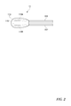
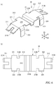
- FIG. 1 It is a perspective view which shows the appearance of the temperature sensor which concerns on one Embodiment of this invention. It is a top view which shows the temperature sensitive element provided in the temperature sensor shown in FIG. It is a side view which shows the lead wire of a holding member and a temperature sensitive element from the direction of the arrow III of FIG.
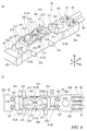
- A) is a perspective view which shows the holding member.
- B) is a plan view showing a holding member.
- A) and (b) are perspective views and plan views showing holding members and leaf springs. The temperature sensitive element is indicated by the alternate long and short dash line.
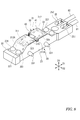
- (A) and (b) are perspective views and plan views showing a leaf spring as a heat collecting member.
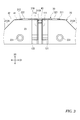
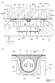
- FIG. 1 is a cross-sectional view taken along the line VIIa-VIIa of FIG.
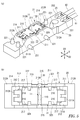
- B is an enlarged view of part VIIb of (a). It is a perspective view which shows the state which the inner film is provided on the holding member. It is a schematic diagram which shows the internal structure of the printer equipped with the temperature sensor shown in FIG.
- the temperature detection device 1 includes a temperature sensor 10, a circuit unit 8, and electric wires 81 and 82 for electrically connecting the temperature sensor 10 and the circuit unit 8. ..
- the temperature sensor 10 is arranged at a position facing the temperature measuring object 7 (see FIG. 7A) so as to maintain the contact state with the temperature measuring object 7.
- the temperature sensor 10 includes a temperature sensing element 11 for detecting the temperature of the temperature measuring object 7, a holding member 20, and a leaf spring 30 as a heat collecting member as main components. Further, the temperature sensor 10 has an inner film 41 (second insulating material) that covers the leaf spring 30 and an outer film 42 that covers the temperature sensing element 11 arranged on the inner film 41 in order to insulate and secure the creepage distance. (First insulating material) is provided. Further, the temperature sensor 10 includes a heat collecting material 43 enclosed around the temperature sensitive element 11 between the inner film 41 and the outer film 42.
- the circuit unit 8 calculates the temperature of the temperature measuring object 7 based on the electric signal output from the temperature sensitive element 11.
- the circuit unit 8 is electrically connected to the temperature sensor 10 via electric wires 81 and 82 drawn from the holding member 20.
- the direction in which the temperature sensor 10 extends in the direction in which the electric wires 81 and 82 are pulled out is referred to as the longitudinal direction D1.
- the direction orthogonal to the longitudinal direction D1 in a plan view is referred to as a width direction D2.
- the direction orthogonal to both the longitudinal direction D1 and the width direction D2 is referred to as the height direction D3.
- the side of the temperature measuring object 7 is referred to as "upper", and the opposite side is referred to as "lower”.
- the side of the temperature measuring object 7 is defined as the surface side Fs.
- the opposite side (holding member 20 side) is defined as the back side Bs.
- the front surface side Fs corresponds to the upper side
- the back surface side Bs corresponds to the lower side.
- the temperature sensitive element 11 includes a temperature sensitive body 110, electrodes 110A and 110B provided on the temperature sensitive body 110, and a pair of lead wires 111 electrically connected to the electrodes 110A and 110B. , 112, and a thermistor element including a covering portion 113 that covers the temperature sensitive body 110.
- a resistor having a temperature coefficient such as a thin film thermistor or a platinum temperature sensor can be widely used.
- the lead wires 111 and 112 are electrically connected to the electric wires 81 and 82 via a pair of conductive members 121 and 122 (FIG. 7A) provided inside the holding member 20, respectively.
- the temperature sensitive body 110 of the temperature sensitive element 11 is arranged in a state of facing the temperature measuring object 7 (FIG. 7 (a)) via the heat collecting material 43 and the outer film 42.
- the holding member 20 will be described with reference to FIGS. 4A and 4B.
- the holding member 20 of the present embodiment is formed in a substantially rectangular shape in a plan view, and is formed by projecting from the main body portion 22 and the vicinity of the center of the main body portion 22 in the longitudinal direction D1 in the height direction D3.
- the pedestal 201 including the above and the electric wire connecting portion 25 to which the electric wires 81 and 82 are connected are provided. Inside the pedestal 201, a rectangular parallelepiped space 20S is formed by being surrounded by the wall body 21.
- a leaf spring 30, which will be described later, is arranged on the surface side Fs (upper side in the height direction D3) of the space 20S.
- the holding member 20 may be formed in a square or circular shape in a plan view depending on the shape of the space 20S and the arrangement of the bosses 221,231 described later.
- the holding member 20 is integrally formed by injection molding using an insulating resin material.
- the upper surface 22a of the main body 22 and the upper surface 25a of the electric wire connecting portion 25 exist, for example, on the same plane.
- the upper surface 22a of the main body 22 is provided with a plurality of first bosses 221 projecting in the height direction D3, and the side surface 23 of the main body 22 is provided with a plurality of first bosses projecting in the width direction D2.
- Two bosses 231 are provided. These first bosses 221 and second bosses 231 are used to attach the films 41 and 42 to the holding member 20.
- the electric wire connecting portion 25 is a portion for attaching electric wires 81 and 82 for electrically connecting the temperature sensitive element 11 and the circuit portion 8, and is a main body portion at one end of the main body portion 22 in the longitudinal direction D1. It is formed integrally with 22.
- the electric wire connecting portion 25 is formed with connection holes 251,252 for connecting the electric wires 81 and 82 to the conductive members 121 and 122 described later, respectively.
- the pedestal 201 is a portion for attaching the leaf spring 30, and is formed in a rectangular shape in a plan view.
- the pedestal portion 201 includes a wall body 21 and a space 20S.
- the wall body 21 includes a pair of first walls 211 and 211 extending in the longitudinal direction D1 and facing the width direction D2, and second walls 212 and 212 connecting both ends of the first walls 211 and 211 in the longitudinal direction D1.
- the first walls 211, 211 and the second walls 212, 212 are both formed so as to rise from the bottom 213 of the pedestal 201 in the height direction D3, and the upper ends of the first walls 211, 211 and the second walls 212, 212 are rectangular. It has an opening 210 in the shape. At the center of the first walls 211 and 211 in the length direction D1, notches 211A and 211A, which are notched in a concave shape, are formed, respectively. Then, the positioning pieces 321 to 324 (FIG. 6), which are a part of the leaf spring 30, are inserted into the space 20S through the opening 210.
- the space 20S maintains heat in the temperature sensitive element 11 by a heat insulating action that suppresses heat conduction from the temperature sensitive element 11 to the outside. By doing so, the resistance value of the temperature sensing element 11 is rapidly changed with respect to the temperature fluctuation of the temperature measuring object 7 that inputs heat to the temperature sensing element 11, and the responsiveness as the temperature sensor 10 is improved. ..
- the space 20S is provided with a cross-sectional area (area in the D1 and D2 directions) and a thickness (dimensions in the D3 direction) that realize the required thermal resistance.
- the space 20S In order to reduce the thermal conductivity of the space 20S as much as possible, it is preferable not to arrange substances other than air in the space 20S as much as possible. It should be noted that the presence of substances such as gas and liquid other than air in the space 20S is not completely excluded, and if the thermal conductivity can be maintained low, substances other than air should be sealed in the space 20S. Does not interfere. Further, in order to suppress the generation of convection in the space 20S, it is permissible to arrange a plate-shaped member or the like in the space 20S.
- the space 20S may be formed in another shape, for example, a cylindrical shape.
- a support portion 214 for supporting the leaf spring 30 is formed at the upper end (tip) of the second wall 212.
- the support portion 214 is formed flat, and the height of the support portion 214 is set lower than the height of the upper end of the first wall 211.
- the outer surfaces 212A of the pair of second walls 212 are inclined toward each other as they move upward. Therefore, the holding member 20 is formed in a frustum shape in a side view.
- an element support portion 215 that supports the temperature sensitive element 11 via a leaf spring 30, a first contact protrusion 216, and a second contact protrusion 217 are formed.
- the element support portion 215 is formed so as to project inward in the width direction D2 from the positions where the notches 211A and 211A of the pair of first walls 211 are formed.
- the upper end surface of the element support portion 215 and the bottom surface of the notch 211A formed in the first wall 211 are continuous.
- Each element support portion 215 is located at the center of the space 20S in the longitudinal direction D1 and supports the leaf spring 30 at a position corresponding to the temperature sensitive body 110.
- the first contact protrusions 216 are formed at two positions on both sides of the element support portion 215 on the pair of first walls 211. Each of the first contact protrusions 216 protrudes from the first wall 211, and the tip of the first contact protrusion 216 comes into contact with the surfaces of the positioning pieces 321 to 324 of the heat collecting member 30. Further, the second contact protrusions 217 are formed at the four corners of the bottom portion 213 in the vicinity of the first contact protrusions 216, and the tips of the second contact protrusions 217 come into contact with the side surfaces of the positioning pieces 321 to 324.
- the leaf spring 30 is positioned in the longitudinal direction D1 and the width direction D2 by the first contact projection 216 and the second contact projection 217, and is maintained in a state as far as possible from the wall body 21.
- the first contact protrusion 216 is formed so as to project in an arc shape from the first wall 211. Further, the upper end of the first contact protrusion 216 has a tapered shape for guiding the positioning pieces 321 to 324 when the leaf spring 30 is inserted. The height of the first contact protrusion 216 is set lower on the tip side than the base end on the first wall 211 side. Similarly, the upper end of the second contact protrusion 217 is also formed in a tapered shape.
- plate-shaped conductive members 121 and 122 are provided inside the bottom portion 213 of the pedestal 201.
- the conductive members 121 and 122 can be insert-molded by arranging them in the injection molding die of the holding member 20.
- Connection holes 241,242 are formed in the bottom portion 213 so as to penetrate in the height direction D3.
- the conductive members 121 and 122 are arranged so as to project inside the connection holes 241,242.
- the lead wires 111 and 112 extend to one side of the leaf spring 30 in the width direction D2 and extend to the inside of the bottom portion 213 via the side surface 23 of the holding member 20.
- the first boss 221 and the second boss 231 are integrally formed with the holding member 20.
- Two first bosses 221 are arranged on the upper surface of the main body 22 with the pedestal 201 sandwiched in the longitudinal direction D1, and two second bosses 231 are arranged on both side surfaces 23 of the holding member 20. This is an example, and the first boss 221 and the second boss 231 can be formed at appropriate positions on the holding member 20.
- the leaf springs 30 are for pressurizing the temperature measuring object 7 from the back surface side Bs by an elastic force and thermally coupling to the temperature sensitive element 11.
- the leaf spring 30 is generally a metal material having a higher thermal conductivity than a resin material or the like, or the thermal conductivity of the metal material. It can be integrally formed by using another material having a thermal conductivity comparable to that of the above, for example, a metal material such as a copper alloy or stainless steel, or a material containing carbon.
- the leaf spring 30 can be formed by stamping and bending. The material used for the leaf spring 30 can be appropriately selected in consideration of thermal conductivity, springiness, and heat resistance.
- the leaf thickness of the leaf spring 30 is preferably as thin as possible so as to ensure strength in order to avoid a decrease in responsiveness due to an increase in heat capacity.
- the leaf thickness of the leaf spring 30 is, for example, about 0.05 to 0.2 mm.
- the heat collecting action of the leaf spring 30 immediately causes a change in the resistance value of the temperature sensitive element 11 with respect to the temperature fluctuation of the temperature measuring object 7, and the temperature sensor 10 serves as the temperature sensor 10. The responsiveness can be further improved.
- heat collection in the present specification means that the heat input from the temperature measuring object 7 is quickly transferred to the temperature sensitive element 11. Due to the heat collecting action of the leaf spring 30, heat is maintained in the vicinity of the temperature sensitive element 11 and the temperature sensitive element 11.
- the leaf spring 30 includes a main body 31 in which the temperature sensitive element 11 is arranged, and a plurality of positioning pieces 321 to 324 for positioning the leaf spring 30 on the holding member 20.
- the main body 31 is formed in a substantially rectangular shape in a plan view.
- the main body 31 includes a contact portion 310 that is pressed against the temperature measuring object 7, and spring pieces 311, 312 as a pair of leg portions that form both ends of the contact portion 310 in the longitudinal direction D1.
- the contact portion 310 is provided with a groove 310A as an element arranging portion in which a part of the temperature sensitive body 110 and the lead wires 111 and 112 is arranged.
- the groove 310A extends in the lateral direction (width direction D2) of the main body 31 and bends in the out-of-plane direction of the main body 31 to form a concave shape.
- the groove 310A is formed from one end to the other end of the contact portion 310 in the width direction D2.
- the groove 310A is set to a width (dimension in the longitudinal direction D1) and a depth capable of accommodating the temperature sensitive body 110 even if the dimensions and shape of the temperature sensitive body 110 vary due to tolerance.
- the responsiveness can be improved by sufficiently injecting heat from the temperature measuring object 7 into the lead wires 111 and 112 (particularly the Jumet wire in the vicinity of the temperature sensitive body 110) having a higher thermal conductivity than the temperature sensitive body 110. Therefore, in consideration of the position where the temperature sensitive body 110 of the temperature sensitive element 11 is arranged, it is preferable that the longest possible section of the lead wires 111 and 112 is arranged in the groove 310A. For example, by arranging the temperature sensitive body 110 so as to be offset outward from the center of the groove 310A formed in the leaf spring 30 in the width direction D2, the section arranged in the groove 310A of the lead wires 111 and 112 is lengthened. can do.
- the contact portion 310 is formed to be substantially flat except for the groove 310A, and is pressed against the temperature measuring object 7 over the entire length direction D1.
- the contact portions 310 supported by the spring pieces 311, 312 at both ends bend between both ends due to the reaction force from the temperature measuring object 7, whereby the temperature sensing element 11 is separated from the temperature measuring object 7.
- the contact portion 310 is supported by the element support portion 215 of the holding member 20 at the position of the groove 310A in order to avoid the above.
- the contact portion 310 may be formed with a recess having the same shape as the outer shape of the temperature sensitive body 110 instead of the groove 310A.
- the spring pieces 311, 312 project from the contact portion 310 to both sides in the longitudinal direction D1 and are bent so as to incline downward with respect to the surface of the contact portion 310, and the respective tips 311A and 312A are support portions. It is bent in the surface direction of the contact portion 310 so as to make surface contact with 214.
- the spring pieces 311, 312 are supported by a support portion 214 formed at a position lower than the first wall 211 between the pair of first wall 211 of the holding member 20. Therefore, when the contact portion 310 is pressed against the temperature measuring object 7 and the spring pieces 311, 312 are displaced on the support portion 214, the spring pieces 311, 312 are elastically deformed without interfering with the second wall 212.
- the temperature measuring object 7 can be sufficiently pressurized as the leaf spring 30. Since the tips 311A and 312A of the spring pieces 311, 312 are formed by bending so as to make surface contact with the support portion 214, the spring pieces 311, 312 when the spring pieces 311, 312 slide on the support portion 214 It is difficult to damage the holding member 20. It is preferable that the leaf spring 30 and the holding member 20 have as little contact area as possible. This is because heat escapes to the holding member 20 through the contacting portion. Therefore, the spring pieces 311, 312 of the leaf spring 30 in the present embodiment are formed in a bifurcated shape in order to reduce the contact area with the support portion 214.
- the positioning pieces 321 to 324 are formed on both sides of the contact portion 310 in the width direction D2. These positioning portions 321 to 324 are provided close to the four corners of the abutting portion 310, respectively, and the abutting portion 310 is bent in the thickness direction D3 to form a downward protrusion.
- the positioning pieces 321 to 324 are continuous from the portion 313 whose width is reduced in the contact portion 310.
- the width of the abutting portion 310 is reduced with respect to the groove 310A on both sides in the longitudinal direction D1 with the step 310B as a boundary.
- the contact portion 310 comes into surface contact with the temperature measuring object 7, and the leaf spring 30 is pressed by the temperature measuring object 7. Then, the spring pieces 311, 312 of the leaf spring 30 are elastically deformed while being displaced on the support portion 214 toward the outside of the longitudinal direction D1 orthogonal to the pressing direction (D3). At this time, the elastic force of the spring pieces 311, 312 pressurizes the main body 31 toward the temperature measuring object 7.
- the inner film 41 is provided on the holding member 20 in order to insulate the leaf spring 30 and the temperature sensitive element 11.
- the inner film 41 has an insulating property, is inserted inside the groove 310A as shown in FIGS. 7 (b) and 8 and is interposed between the leaf spring 30 and the temperature sensitive element 11.
- the inner film 41 covers the surface of the leaf spring 30 from the temperature measuring object 7 side to the entire surface in order to secure a sufficient creepage distance from the temperature sensitive element 11.
- the inner film 41 for example, a resin material such as polyimide or fluororesin is used.
- the thickness of the inner film 41 is, for example, about 10 to 20 ⁇ m.
- the inner film 41 is given a width equivalent to the width of the pedestal 201 and is formed in a rectangular shape.
- the inner film 41 is not always necessary even if the leaf spring 30 has conductivity.
- the leaf spring 30 is a non-conductive member such as a resin molded product, the arrangement of the inner film 41 can be omitted.
- the leaf spring 30 and the temperature sensitive element 11 are thermally coupled to each other via the inner film 41.
- Heat collector In the gap G1 (FIG. 7 (b)) around the temperature sensitive element 11 arranged in the groove 310A, heat is collected by the temperature sensitive element 11 and therefore has an insulating property that thermally couples to the temperature sensitive element 11. It is preferable that the heat collecting material 43 (FIGS. 7 (b) and 8) is filled.
- the heat collecting material 43 for example, a material containing a dispersion medium such as a silicone resin having a high thermal conductivity and an insulating dispersant such as ceramic powder is used among the resin materials. Further, so-called heat conductive grease or silicone oil compound can be used for the heat collecting material 43.
- the heat collecting material 43 is filled from above the inner film 41. The heat collecting material 43 adheres to the temperature sensitive element 11 and also adheres to the leaf spring 30 via the inner film 41, so that the leaf spring 30 is more sufficiently thermally coupled to the temperature sensitive element 11. The responsiveness can be further improved.
- the outer film 42 has an insulating property, covers the leaf spring 30 and the holding member 20 from the temperature measuring object 7 side, and is interposed between the temperature sensing element 11 and the temperature measuring object 7 to both of them. Is provided to insulate. Further, the outer film 42 holds the temperature sensitive element 11 on the leaf spring 30. As shown in FIGS. 1 and 7A, the outer film 42 covers the temperature sensitive element 11 from above the inner film 41 and is fixed to both side surfaces 23 of the holding member 20. In addition, the outer film 42 includes the holding member including both side surfaces 23 of the holding member 20 in addition to the entire leaf spring 30 in order to secure a sufficient creepage distance from the temperature sensitive element 11 and the conductive members 121 and 122. It covers most of the 20.
- the outer film 42 for example, a resin material such as polyimide or fluororesin is used. As shown in FIG. 7B, the outer film 42 may be a laminate of two or more film materials. The total thickness of the outer film 42 is, for example, about 10 to 20 ⁇ m.
- the temperature sensor 10 can be assembled, for example, by the following procedure.
- the ends of the lead wires 111 and 112 of the temperature sensitive element 11 are joined to the conductive members 121 and 122 (FIG. 7 (a)) in a state of being insert-molded into the holding member 20 by electrical welding or the like.
- the positioning pieces 321 to 324 of the leaf spring 30 are inserted inside the wall body 21 of the holding member 20 shown in FIGS. 4A and 4B. At this time, the tips (lower ends) of the positioning pieces 321 to 324 are not in contact with the bottom portion 213. Further, when the leaf spring 30 is pushed inside the wall body 21, the tips of the positioning pieces 321 to 324 abut on the bottom portion 213, and at this time, the positioning pieces 321 to 324 function as stoppers.
- the leaf spring 30 is assembled to the holding member 20 in a state where the spring pieces 311, 312 are supported by the support portion 214. At this time, the contact portion 310 projects upward from the upper end of the first wall 211. A space 20S is partitioned on the back side Bs of the leaf spring 30.
- the leaf spring 30 is covered with the inner film 41, and the first boss 221 passed through the holes provided at the four corners of the inner film 41 is subjected to heat and pressure to be inside by heat caulking.
- the film 41 is fixed to the holding member 20.
- the lead wires 111 and 112 are routed and the temperature sensitive element 11 is assembled to the holding member 20 and the leaf spring 30. Specifically, the lead wires 111 and 112 are bent upward from the conductive members 121 and 122 along the side surface 23 of the holding member 20 and then bent at the position of the groove 310A of the leaf spring 30 to spread the inner film 41.
- the temperature sensitive body 110 is housed inside the groove 310A.
- the heat collecting material 43 is applied to the temperature sensitive body 110.
- the heat collecting material 43 adheres to the temperature sensitive body 110 and the lead wires 111 and 112 drawn from the temperature sensitive body 110.
- the outer film 42 covers most of the holding member 20 including the temperature sensitive element 11 and the heat collecting material 43, and the second boss is similar to the first boss 221.
- the outer film 42 is fixed to the holding member 20 by heat caulking of 231. As described above, the assembly of the temperature sensor 10 is completed.
- the contact portion 310 thermally couples to the temperature measuring object 7 in addition to the temperature sensing element 11. Even if a gap is left between the temperature sensitive element 11 and the contact portion 310 when the assembly of the temperature sensor 10 is completed, the heat collecting material 43 feels due to the pressurization of the temperature measuring object 7 by the leaf spring 30. The warm body 110 and its vicinity are filled with substantially no gap. Therefore, the temperature sensitive element 11 and the leaf spring 30 can be more sufficiently thermally coupled.
- the positioning pieces 321 to 324 and the spring pieces 311, 312 of the leaf spring 30 are in contact with the holding member 20 at the minimum necessary, the outflow of heat to the holding member 20 through the leaf spring 30 is suppressed. .. According to this, the heat collecting action of the leaf spring 30, and the heat insulating action of the space 20S having a lower thermal conductivity than the heat insulating material such as ceramic paper, the heat transferred from the temperature measuring object 7 is obtained. Can be more securely fastened to the temperature sensitive element 11 and its vicinity. Therefore, according to the temperature sensor 10 of the present embodiment, the temperature sensitive element 11 can immediately follow the temperature change of the temperature measuring object 7, and a good responsiveness of the detected temperature can be realized.
- the thin leaf spring 30 and the space 20S partitioned on the back surface side Bs have both heat insulating performance and an elastic force for pressurizing the temperature sensor 10 on the temperature measuring object 7. While keeping the temperature sensor 10 compact, it is possible to realize responsiveness equal to or higher than that without using so-called ceramic paper.
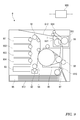
- the laser printer 9 includes a photoconductor belt 91, a charger 92, an exposure device 93, developers 901 to 904, a guide roller 94, an intermediate transfer unit 95, and a paper feed cassette 96.
- a control device 900 for controlling each part of the laser printer 9.
- the fuser 99 includes a pressure roller 991 and a heating roller 992.
- the heating roller 992 has a built-in heater (not shown) as a heat source.
- the temperature sensor 10 is installed by pressing against the heater or the member in order to measure the temperature of the heater built in the heating roller 992 or the temperature of the member provided in the heater.
- the recording paper 913 to which the color toner image is transferred is transferred to the pressurizing roller 991 and the heating roller 992 of the fixing device 99. It is sent out between and. By pressurizing and heating the recording paper 913 while passing between the pressure roller 991 and the heating roller 992, the color toner image is fixed on the recording paper 913. After that, the recording paper 913 is discharged to the paper ejection tray 912 via the paper ejection roller 911.
- the control device 900 controls the energization state of the heating roller 992 to the heater by using the temperature measurement value obtained by the temperature sensor 10 and the circuit unit 8 to which the temperature sensor 10 is connected.
- the control device 900 stops energizing the heater of the heating roller 992 when the measured temperature value exceeds the threshold value. Since the surface temperature of the heating roller 992 is measured by the temperature sensor 10 with good followability, the energized state of the heater is appropriately controlled without excessively heating the heating roller 992 by the heater in anticipation of a delay in the measurement response. be able to.
- a case where a thermistor element having a configuration in which lead wires 111 and 112 extend in one direction from one side of the temperature sensitive body 110 is used is illustrated and described.
- a thermistor element in which the lead wires 111 and 112 extend in both directions of the temperature sensitive body 110 may be used.
- the lead wires 111 and 112 extend into the holding member 20 via both side surfaces 23 of the holding member 20.
- the case where the lead wires 111 and 112 are drawn out from the temperature sensitive body 110 in the width direction D2 is illustrated and described, but the lead wires 111 and 112 are drawn from the temperature sensitive body 110 in the longitudinal direction. It may be pulled out to D1.
- the shape of the leaf spring 30 is not limited to the above embodiment, and various modifications can be made.
- a protrusion for positioning the leaf spring 30 can be formed on the holding member 20 between the bifurcated portions of the spring pieces 311, 312. In that case, the positioning pieces 321 to 324 extending downward from the contact portion 310 are not required.
- Temperature detection device Temperature measurement object 8 Circuit part 9
- Laser printer 10
- Temperature sensor 11
- Temperature sensitive element 20
- Holding member 20S Space 21
- Wall body 22 Main body part 23
- Side surface 25
- Electric wire connection part 30
- Leaf spring (heat collecting member) 31
- Main body 41
- Inner film (second insulating material) 42
- Outer film (first insulating material) 43
- Heat collector 81, 82
- Electric wire 91
- Photoreceptor belt 92
- Exposure device 94
- Exposure device 94
- Intermediate transfer unit 96
- Paper cassette 97
- Paper feed roller 98 Transfer roller 99
- Fixer 110
- Pedestal 210 Opening 211 First wall 211A Notch 212
- Second wall 212A Outer surface 213
- Bottom part Support part 215
- Element support part 216
- First contact protrusion (contact protrusion) 217
Landscapes
- Physics & Mathematics (AREA)
- General Physics & Mathematics (AREA)
- Nonlinear Science (AREA)
- Measuring Temperature Or Quantity Of Heat (AREA)
- Fixing For Electrophotography (AREA)
Priority Applications (1)
| Application Number | Priority Date | Filing Date | Title |
|---|---|---|---|
| US17/905,204 US12416531B2 (en) | 2020-04-15 | 2020-12-17 | Temperature sensor, temperature detection device and image formation device |
Applications Claiming Priority (2)
| Application Number | Priority Date | Filing Date | Title |
|---|---|---|---|
| JP2020-072858 | 2020-04-15 | ||
| JP2020072858A JP7034201B2 (ja) | 2020-04-15 | 2020-04-15 | 温度センサ、温度検出装置および画像形成装置 |
Publications (1)
| Publication Number | Publication Date |
|---|---|
| WO2021210218A1 true WO2021210218A1 (ja) | 2021-10-21 |
Family
ID=78084209
Family Applications (1)
| Application Number | Title | Priority Date | Filing Date |
|---|---|---|---|
| PCT/JP2020/047200 Ceased WO2021210218A1 (ja) | 2020-04-15 | 2020-12-17 | 温度センサ、温度検出装置および画像形成装置 |
Country Status (3)
| Country | Link |
|---|---|
| US (1) | US12416531B2 (enExample) |
| JP (1) | JP7034201B2 (enExample) |
| WO (1) | WO2021210218A1 (enExample) |
Families Citing this family (2)
| Publication number | Priority date | Publication date | Assignee | Title |
|---|---|---|---|---|
| JP7538158B2 (ja) | 2022-01-28 | 2024-08-21 | 株式会社芝浦電子 | 温度センサ、温度検出装置、および画像形成装置 |
| JP1729419S (ja) * | 2022-03-18 | 2022-11-09 | 温度センサ |
Citations (4)
| Publication number | Priority date | Publication date | Assignee | Title |
|---|---|---|---|---|
| JPS62161342A (ja) * | 1986-01-11 | 1987-07-17 | 松下電工株式会社 | 体温計 |
| JPH04115131A (ja) * | 1990-09-04 | 1992-04-16 | Technol Seven Co Ltd | 温度検出装置 |
| JPH09218102A (ja) * | 1996-02-08 | 1997-08-19 | Fuji Xerox Co Ltd | 温度検知装置 |
| US6252207B1 (en) * | 1999-11-19 | 2001-06-26 | Nexpress Solutions Llc | Fuser temperature control sensor which is insensitive to surrounding air currents |
Family Cites Families (6)
| Publication number | Priority date | Publication date | Assignee | Title |
|---|---|---|---|---|
| DE69223356T2 (de) * | 1991-09-06 | 1998-03-26 | Konishiroku Photo Ind | Fixiervorrichtung mit Temperaturmesseinrichtung |
| JP4566380B2 (ja) | 2000-10-13 | 2010-10-20 | キヤノン株式会社 | 加熱定着装置 |
| JP2012163354A (ja) | 2011-02-03 | 2012-08-30 | Omron Healthcare Co Ltd | 電子体温計 |
| CN204228287U (zh) | 2014-08-21 | 2015-03-25 | 深圳市敏杰电子科技有限公司 | 防热辐射ntc温度传感器 |
| JP7538158B2 (ja) * | 2022-01-28 | 2024-08-21 | 株式会社芝浦電子 | 温度センサ、温度検出装置、および画像形成装置 |
| US12353149B2 (en) * | 2022-01-31 | 2025-07-08 | Canon Kabushiki Kaisha | Temperature detection device, fixing apparatus, and image forming apparatus |
-
2020
- 2020-04-15 JP JP2020072858A patent/JP7034201B2/ja active Active
- 2020-12-17 WO PCT/JP2020/047200 patent/WO2021210218A1/ja not_active Ceased
- 2020-12-17 US US17/905,204 patent/US12416531B2/en active Active
Patent Citations (4)
| Publication number | Priority date | Publication date | Assignee | Title |
|---|---|---|---|---|
| JPS62161342A (ja) * | 1986-01-11 | 1987-07-17 | 松下電工株式会社 | 体温計 |
| JPH04115131A (ja) * | 1990-09-04 | 1992-04-16 | Technol Seven Co Ltd | 温度検出装置 |
| JPH09218102A (ja) * | 1996-02-08 | 1997-08-19 | Fuji Xerox Co Ltd | 温度検知装置 |
| US6252207B1 (en) * | 1999-11-19 | 2001-06-26 | Nexpress Solutions Llc | Fuser temperature control sensor which is insensitive to surrounding air currents |
Also Published As
| Publication number | Publication date |
|---|---|
| JP7034201B2 (ja) | 2022-03-11 |
| JP2021169954A (ja) | 2021-10-28 |
| US20230143488A1 (en) | 2023-05-11 |
| US12416531B2 (en) | 2025-09-16 |
Similar Documents
| Publication | Publication Date | Title |
|---|---|---|
| JP5333500B2 (ja) | 定着装置 | |
| JP5234134B2 (ja) | 定着装置 | |
| US6455811B2 (en) | Image heating apparatus and heater used in this apparatus | |
| JP7034201B2 (ja) | 温度センサ、温度検出装置および画像形成装置 | |
| US9020408B2 (en) | Fixing device | |
| US9037057B2 (en) | Fixing device capable of suppressing contact between tubular member and electric components | |
| US11334011B2 (en) | Heating device for an image forming unit of an image forming apparatus | |
| JP7538158B2 (ja) | 温度センサ、温度検出装置、および画像形成装置 | |
| JP2020101674A (ja) | 定着装置及び画像形成装置 | |
| JP2019090938A (ja) | 定着装置及び画像形成装置 | |
| JP5790688B2 (ja) | 定着装置 | |
| JP2021039233A (ja) | 定着装置及び画像形成装置 | |
| JP2505866Y2 (ja) | 感光体ドラム用温度検知器 | |
| CN115039039B (zh) | 定影装置和图像形成装置 | |
| JP2014174127A (ja) | 赤外線センサ装置 | |
| JP7304328B2 (ja) | 温度センサ、および、加熱器 | |
| JP7713155B2 (ja) | 加熱装置、定着装置、画像形成装置 | |
| EP4468086A1 (en) | Heating device and image forming apparatus | |
| US11934124B2 (en) | Heating device | |
| JP3519855B2 (ja) | 熱定着装置の温度検知手段 | |
| JP2023111826A (ja) | 温度検出装置、定着装置及び画像形成装置 | |
| JPS6285831A (ja) | 温度検知装置 | |
| JP2008076934A (ja) | ヒータ、加熱装置、画像形成装置 | |
| JP2020101675A (ja) | 定着装置及び画像形成装置 |
Legal Events
| Date | Code | Title | Description |
|---|---|---|---|
| 121 | Ep: the epo has been informed by wipo that ep was designated in this application |
Ref document number: 20930860 Country of ref document: EP Kind code of ref document: A1 |
|
| NENP | Non-entry into the national phase |
Ref country code: DE |
|
| 122 | Ep: pct application non-entry in european phase |
Ref document number: 20930860 Country of ref document: EP Kind code of ref document: A1 |
|
| WWG | Wipo information: grant in national office |
Ref document number: 17905204 Country of ref document: US |