WO2021206088A1 - 剥離容器および剥離容器の製造方法 - Google Patents
剥離容器および剥離容器の製造方法 Download PDFInfo
- Publication number
- WO2021206088A1 WO2021206088A1 PCT/JP2021/014634 JP2021014634W WO2021206088A1 WO 2021206088 A1 WO2021206088 A1 WO 2021206088A1 JP 2021014634 W JP2021014634 W JP 2021014634W WO 2021206088 A1 WO2021206088 A1 WO 2021206088A1
- Authority
- WO
- WIPO (PCT)
- Prior art keywords
- layer
- injection molding
- peeling container
- preform
- resin material
- Prior art date
Links
- 238000004519 manufacturing process Methods 0.000 title claims description 19
- 238000000034 method Methods 0.000 title claims description 10
- 229920005989 resin Polymers 0.000 claims abstract description 60
- 239000011347 resin Substances 0.000 claims abstract description 60
- 239000000463 material Substances 0.000 claims abstract description 56
- 230000002093 peripheral effect Effects 0.000 claims abstract description 44
- 230000004323 axial length Effects 0.000 claims abstract description 6
- 238000001746 injection moulding Methods 0.000 claims description 97
- 238000000071 blow moulding Methods 0.000 claims description 44
- 238000003825 pressing Methods 0.000 claims description 5
- 230000000717 retained effect Effects 0.000 claims description 5
- 238000010030 laminating Methods 0.000 claims 1
- 239000010410 layer Substances 0.000 description 168
- 210000003811 finger Anatomy 0.000 description 17
- 230000007723 transport mechanism Effects 0.000 description 13
- 238000002844 melting Methods 0.000 description 10
- 230000008018 melting Effects 0.000 description 10
- 238000000465 moulding Methods 0.000 description 9
- 238000002347 injection Methods 0.000 description 8
- 239000007924 injection Substances 0.000 description 8
- 210000003813 thumb Anatomy 0.000 description 8
- -1 polyethylene terephthalate Polymers 0.000 description 6
- 239000010409 thin film Substances 0.000 description 6
- 239000004743 Polypropylene Substances 0.000 description 5
- 238000010586 diagram Methods 0.000 description 5
- 230000007246 mechanism Effects 0.000 description 5
- 229920000139 polyethylene terephthalate Polymers 0.000 description 5
- 239000005020 polyethylene terephthalate Substances 0.000 description 5
- 239000002537 cosmetic Substances 0.000 description 4
- 238000010438 heat treatment Methods 0.000 description 4
- 239000007788 liquid Substances 0.000 description 4
- 239000004698 Polyethylene Substances 0.000 description 3
- 238000001816 cooling Methods 0.000 description 3
- 229920000728 polyester Polymers 0.000 description 3
- 238000012546 transfer Methods 0.000 description 3
- 229920000089 Cyclic olefin copolymer Polymers 0.000 description 2
- 229920000491 Polyphenylsulfone Polymers 0.000 description 2
- 230000004888 barrier function Effects 0.000 description 2
- 230000007547 defect Effects 0.000 description 2
- 238000009826 distribution Methods 0.000 description 2
- 230000003028 elevating effect Effects 0.000 description 2
- 235000011194 food seasoning agent Nutrition 0.000 description 2
- 230000000149 penetrating effect Effects 0.000 description 2
- 229920003207 poly(ethylene-2,6-naphthalate) Polymers 0.000 description 2
- 229920000747 poly(lactic acid) Polymers 0.000 description 2
- 229920000573 polyethylene Polymers 0.000 description 2
- 239000011112 polyethylene naphthalate Substances 0.000 description 2
- 239000004626 polylactic acid Substances 0.000 description 2
- 235000013555 soy sauce Nutrition 0.000 description 2
- 229920003002 synthetic resin Polymers 0.000 description 2
- 239000000057 synthetic resin Substances 0.000 description 2
- FDSYTWVNUJTPMA-UHFFFAOYSA-N 2-[3,9-bis(carboxymethyl)-3,6,9,15-tetrazabicyclo[9.3.1]pentadeca-1(15),11,13-trien-6-yl]acetic acid Chemical compound C1N(CC(O)=O)CCN(CC(=O)O)CCN(CC(O)=O)CC2=CC=CC1=N2 FDSYTWVNUJTPMA-UHFFFAOYSA-N 0.000 description 1
- 229920001634 Copolyester Polymers 0.000 description 1
- 229920002845 Poly(methacrylic acid) Polymers 0.000 description 1
- NIXOWILDQLNWCW-UHFFFAOYSA-N acrylic acid group Chemical group C(C=C)(=O)O NIXOWILDQLNWCW-UHFFFAOYSA-N 0.000 description 1
- 238000013459 approach Methods 0.000 description 1
- 238000006243 chemical reaction Methods 0.000 description 1
- 238000013461 design Methods 0.000 description 1
- 230000006866 deterioration Effects 0.000 description 1
- 238000007599 discharging Methods 0.000 description 1
- 230000000694 effects Effects 0.000 description 1
- 230000007613 environmental effect Effects 0.000 description 1
- 238000001125 extrusion Methods 0.000 description 1
- 125000002496 methyl group Chemical group [H]C([H])([H])* 0.000 description 1
- 238000012986 modification Methods 0.000 description 1
- 230000004048 modification Effects 0.000 description 1
- 230000003647 oxidation Effects 0.000 description 1
- 238000007254 oxidation reaction Methods 0.000 description 1
- 229920003229 poly(methyl methacrylate) Polymers 0.000 description 1
- 239000004926 polymethyl methacrylate Substances 0.000 description 1
- 229920001155 polypropylene Polymers 0.000 description 1
- 230000008569 process Effects 0.000 description 1
- 238000003303 reheating Methods 0.000 description 1
- 230000004044 response Effects 0.000 description 1
- 239000002356 single layer Substances 0.000 description 1
- 239000000126 substance Substances 0.000 description 1
- 150000003457 sulfones Chemical class 0.000 description 1
- KKEYFWRCBNTPAC-UHFFFAOYSA-L terephthalate(2-) Chemical compound [O-]C(=O)C1=CC=C(C([O-])=O)C=C1 KKEYFWRCBNTPAC-UHFFFAOYSA-L 0.000 description 1
- 229920005992 thermoplastic resin Polymers 0.000 description 1
Images


Classifications
-
- B—PERFORMING OPERATIONS; TRANSPORTING
- B65—CONVEYING; PACKING; STORING; HANDLING THIN OR FILAMENTARY MATERIAL
- B65D—CONTAINERS FOR STORAGE OR TRANSPORT OF ARTICLES OR MATERIALS, e.g. BAGS, BARRELS, BOTTLES, BOXES, CANS, CARTONS, CRATES, DRUMS, JARS, TANKS, HOPPERS, FORWARDING CONTAINERS; ACCESSORIES, CLOSURES, OR FITTINGS THEREFOR; PACKAGING ELEMENTS; PACKAGES
- B65D1/00—Containers having bodies formed in one piece, e.g. by casting metallic material, by moulding plastics, by blowing vitreous material, by throwing ceramic material, by moulding pulped fibrous material, by deep-drawing operations performed on sheet material
- B65D1/02—Bottles or similar containers with necks or like restricted apertures, designed for pouring contents
- B65D1/0207—Bottles or similar containers with necks or like restricted apertures, designed for pouring contents characterised by material, e.g. composition, physical features
- B65D1/0215—Bottles or similar containers with necks or like restricted apertures, designed for pouring contents characterised by material, e.g. composition, physical features multilayered
-
- B—PERFORMING OPERATIONS; TRANSPORTING
- B29—WORKING OF PLASTICS; WORKING OF SUBSTANCES IN A PLASTIC STATE IN GENERAL
- B29C—SHAPING OR JOINING OF PLASTICS; SHAPING OF MATERIAL IN A PLASTIC STATE, NOT OTHERWISE PROVIDED FOR; AFTER-TREATMENT OF THE SHAPED PRODUCTS, e.g. REPAIRING
- B29C45/00—Injection moulding, i.e. forcing the required volume of moulding material through a nozzle into a closed mould; Apparatus therefor
- B29C45/03—Injection moulding apparatus
- B29C45/04—Injection moulding apparatus using movable moulds or mould halves
- B29C45/06—Injection moulding apparatus using movable moulds or mould halves mounted on a turntable, i.e. on a rotating support having a rotating axis parallel to the mould opening, closing or clamping direction
-
- B—PERFORMING OPERATIONS; TRANSPORTING
- B29—WORKING OF PLASTICS; WORKING OF SUBSTANCES IN A PLASTIC STATE IN GENERAL
- B29C—SHAPING OR JOINING OF PLASTICS; SHAPING OF MATERIAL IN A PLASTIC STATE, NOT OTHERWISE PROVIDED FOR; AFTER-TREATMENT OF THE SHAPED PRODUCTS, e.g. REPAIRING
- B29C45/00—Injection moulding, i.e. forcing the required volume of moulding material through a nozzle into a closed mould; Apparatus therefor
- B29C45/16—Making multilayered or multicoloured articles
- B29C45/1635—Making multilayered or multicoloured articles using displaceable mould parts, e.g. retractable partition between adjacent mould cavities
-
- B—PERFORMING OPERATIONS; TRANSPORTING
- B29—WORKING OF PLASTICS; WORKING OF SUBSTANCES IN A PLASTIC STATE IN GENERAL
- B29C—SHAPING OR JOINING OF PLASTICS; SHAPING OF MATERIAL IN A PLASTIC STATE, NOT OTHERWISE PROVIDED FOR; AFTER-TREATMENT OF THE SHAPED PRODUCTS, e.g. REPAIRING
- B29C45/00—Injection moulding, i.e. forcing the required volume of moulding material through a nozzle into a closed mould; Apparatus therefor
- B29C45/17—Component parts, details or accessories; Auxiliary operations
- B29C45/26—Moulds
-
- B—PERFORMING OPERATIONS; TRANSPORTING
- B29—WORKING OF PLASTICS; WORKING OF SUBSTANCES IN A PLASTIC STATE IN GENERAL
- B29C—SHAPING OR JOINING OF PLASTICS; SHAPING OF MATERIAL IN A PLASTIC STATE, NOT OTHERWISE PROVIDED FOR; AFTER-TREATMENT OF THE SHAPED PRODUCTS, e.g. REPAIRING
- B29C49/00—Blow-moulding, i.e. blowing a preform or parison to a desired shape within a mould; Apparatus therefor
- B29C49/02—Combined blow-moulding and manufacture of the preform or the parison
- B29C49/06—Injection blow-moulding
- B29C49/061—Injection blow-moulding with parison holding means displaceable between injection and blow stations
- B29C49/062—Injection blow-moulding with parison holding means displaceable between injection and blow stations following an arcuate path, e.g. rotary or oscillating-type
-
- B—PERFORMING OPERATIONS; TRANSPORTING
- B29—WORKING OF PLASTICS; WORKING OF SUBSTANCES IN A PLASTIC STATE IN GENERAL
- B29C—SHAPING OR JOINING OF PLASTICS; SHAPING OF MATERIAL IN A PLASTIC STATE, NOT OTHERWISE PROVIDED FOR; AFTER-TREATMENT OF THE SHAPED PRODUCTS, e.g. REPAIRING
- B29C49/00—Blow-moulding, i.e. blowing a preform or parison to a desired shape within a mould; Apparatus therefor
- B29C49/071—Preforms or parisons characterised by their configuration, e.g. geometry, dimensions or physical properties
-
- B—PERFORMING OPERATIONS; TRANSPORTING
- B29—WORKING OF PLASTICS; WORKING OF SUBSTANCES IN A PLASTIC STATE IN GENERAL
- B29C—SHAPING OR JOINING OF PLASTICS; SHAPING OF MATERIAL IN A PLASTIC STATE, NOT OTHERWISE PROVIDED FOR; AFTER-TREATMENT OF THE SHAPED PRODUCTS, e.g. REPAIRING
- B29C49/00—Blow-moulding, i.e. blowing a preform or parison to a desired shape within a mould; Apparatus therefor
- B29C49/08—Biaxial stretching during blow-moulding
- B29C49/10—Biaxial stretching during blow-moulding using mechanical means for prestretching
- B29C49/12—Stretching rods
-
- B—PERFORMING OPERATIONS; TRANSPORTING
- B29—WORKING OF PLASTICS; WORKING OF SUBSTANCES IN A PLASTIC STATE IN GENERAL
- B29C—SHAPING OR JOINING OF PLASTICS; SHAPING OF MATERIAL IN A PLASTIC STATE, NOT OTHERWISE PROVIDED FOR; AFTER-TREATMENT OF THE SHAPED PRODUCTS, e.g. REPAIRING
- B29C49/00—Blow-moulding, i.e. blowing a preform or parison to a desired shape within a mould; Apparatus therefor
- B29C49/22—Blow-moulding, i.e. blowing a preform or parison to a desired shape within a mould; Apparatus therefor using multilayered preforms or parisons
-
- B—PERFORMING OPERATIONS; TRANSPORTING
- B65—CONVEYING; PACKING; STORING; HANDLING THIN OR FILAMENTARY MATERIAL
- B65D—CONTAINERS FOR STORAGE OR TRANSPORT OF ARTICLES OR MATERIALS, e.g. BAGS, BARRELS, BOTTLES, BOXES, CANS, CARTONS, CRATES, DRUMS, JARS, TANKS, HOPPERS, FORWARDING CONTAINERS; ACCESSORIES, CLOSURES, OR FITTINGS THEREFOR; PACKAGING ELEMENTS; PACKAGES
- B65D1/00—Containers having bodies formed in one piece, e.g. by casting metallic material, by moulding plastics, by blowing vitreous material, by throwing ceramic material, by moulding pulped fibrous material, by deep-drawing operations performed on sheet material
- B65D1/02—Bottles or similar containers with necks or like restricted apertures, designed for pouring contents
- B65D1/0223—Bottles or similar containers with necks or like restricted apertures, designed for pouring contents characterised by shape
-
- B—PERFORMING OPERATIONS; TRANSPORTING
- B65—CONVEYING; PACKING; STORING; HANDLING THIN OR FILAMENTARY MATERIAL
- B65D—CONTAINERS FOR STORAGE OR TRANSPORT OF ARTICLES OR MATERIALS, e.g. BAGS, BARRELS, BOTTLES, BOXES, CANS, CARTONS, CRATES, DRUMS, JARS, TANKS, HOPPERS, FORWARDING CONTAINERS; ACCESSORIES, CLOSURES, OR FITTINGS THEREFOR; PACKAGING ELEMENTS; PACKAGES
- B65D83/00—Containers or packages with special means for dispensing contents
- B65D83/0055—Containers or packages provided with a flexible bag or a deformable membrane or diaphragm for expelling the contents
-
- B—PERFORMING OPERATIONS; TRANSPORTING
- B29—WORKING OF PLASTICS; WORKING OF SUBSTANCES IN A PLASTIC STATE IN GENERAL
- B29C—SHAPING OR JOINING OF PLASTICS; SHAPING OF MATERIAL IN A PLASTIC STATE, NOT OTHERWISE PROVIDED FOR; AFTER-TREATMENT OF THE SHAPED PRODUCTS, e.g. REPAIRING
- B29C45/00—Injection moulding, i.e. forcing the required volume of moulding material through a nozzle into a closed mould; Apparatus therefor
- B29C45/16—Making multilayered or multicoloured articles
- B29C45/1635—Making multilayered or multicoloured articles using displaceable mould parts, e.g. retractable partition between adjacent mould cavities
- B29C2045/1637—Making multilayered or multicoloured articles using displaceable mould parts, e.g. retractable partition between adjacent mould cavities the first injected part and the movable mould part being movable together
-
- B—PERFORMING OPERATIONS; TRANSPORTING
- B29—WORKING OF PLASTICS; WORKING OF SUBSTANCES IN A PLASTIC STATE IN GENERAL
- B29C—SHAPING OR JOINING OF PLASTICS; SHAPING OF MATERIAL IN A PLASTIC STATE, NOT OTHERWISE PROVIDED FOR; AFTER-TREATMENT OF THE SHAPED PRODUCTS, e.g. REPAIRING
- B29C49/00—Blow-moulding, i.e. blowing a preform or parison to a desired shape within a mould; Apparatus therefor
- B29C49/02—Combined blow-moulding and manufacture of the preform or the parison
- B29C2049/023—Combined blow-moulding and manufacture of the preform or the parison using inherent heat of the preform, i.e. 1 step blow moulding
-
- B—PERFORMING OPERATIONS; TRANSPORTING
- B29—WORKING OF PLASTICS; WORKING OF SUBSTANCES IN A PLASTIC STATE IN GENERAL
- B29C—SHAPING OR JOINING OF PLASTICS; SHAPING OF MATERIAL IN A PLASTIC STATE, NOT OTHERWISE PROVIDED FOR; AFTER-TREATMENT OF THE SHAPED PRODUCTS, e.g. REPAIRING
- B29C2949/00—Indexing scheme relating to blow-moulding
- B29C2949/07—Preforms or parisons characterised by their configuration
- B29C2949/0715—Preforms or parisons characterised by their configuration the preform having one end closed
-
- B—PERFORMING OPERATIONS; TRANSPORTING
- B29—WORKING OF PLASTICS; WORKING OF SUBSTANCES IN A PLASTIC STATE IN GENERAL
- B29C—SHAPING OR JOINING OF PLASTICS; SHAPING OF MATERIAL IN A PLASTIC STATE, NOT OTHERWISE PROVIDED FOR; AFTER-TREATMENT OF THE SHAPED PRODUCTS, e.g. REPAIRING
- B29C2949/00—Indexing scheme relating to blow-moulding
- B29C2949/07—Preforms or parisons characterised by their configuration
- B29C2949/076—Preforms or parisons characterised by their configuration characterised by the shape
- B29C2949/0768—Preforms or parisons characterised by their configuration characterised by the shape characterised by the shape of specific parts of preform
- B29C2949/078—Preforms or parisons characterised by their configuration characterised by the shape characterised by the shape of specific parts of preform characterised by the bottom
- B29C2949/0781—Preforms or parisons characterised by their configuration characterised by the shape characterised by the shape of specific parts of preform characterised by the bottom characterised by the sprue, i.e. injection mark
-
- B—PERFORMING OPERATIONS; TRANSPORTING
- B29—WORKING OF PLASTICS; WORKING OF SUBSTANCES IN A PLASTIC STATE IN GENERAL
- B29C—SHAPING OR JOINING OF PLASTICS; SHAPING OF MATERIAL IN A PLASTIC STATE, NOT OTHERWISE PROVIDED FOR; AFTER-TREATMENT OF THE SHAPED PRODUCTS, e.g. REPAIRING
- B29C2949/00—Indexing scheme relating to blow-moulding
- B29C2949/30—Preforms or parisons made of several components
- B29C2949/3008—Preforms or parisons made of several components at neck portion
-
- B—PERFORMING OPERATIONS; TRANSPORTING
- B29—WORKING OF PLASTICS; WORKING OF SUBSTANCES IN A PLASTIC STATE IN GENERAL
- B29C—SHAPING OR JOINING OF PLASTICS; SHAPING OF MATERIAL IN A PLASTIC STATE, NOT OTHERWISE PROVIDED FOR; AFTER-TREATMENT OF THE SHAPED PRODUCTS, e.g. REPAIRING
- B29C2949/00—Indexing scheme relating to blow-moulding
- B29C2949/30—Preforms or parisons made of several components
- B29C2949/3012—Preforms or parisons made of several components at flange portion
-
- B—PERFORMING OPERATIONS; TRANSPORTING
- B29—WORKING OF PLASTICS; WORKING OF SUBSTANCES IN A PLASTIC STATE IN GENERAL
- B29C—SHAPING OR JOINING OF PLASTICS; SHAPING OF MATERIAL IN A PLASTIC STATE, NOT OTHERWISE PROVIDED FOR; AFTER-TREATMENT OF THE SHAPED PRODUCTS, e.g. REPAIRING
- B29C2949/00—Indexing scheme relating to blow-moulding
- B29C2949/30—Preforms or parisons made of several components
- B29C2949/3016—Preforms or parisons made of several components at body portion
-
- B—PERFORMING OPERATIONS; TRANSPORTING
- B29—WORKING OF PLASTICS; WORKING OF SUBSTANCES IN A PLASTIC STATE IN GENERAL
- B29C—SHAPING OR JOINING OF PLASTICS; SHAPING OF MATERIAL IN A PLASTIC STATE, NOT OTHERWISE PROVIDED FOR; AFTER-TREATMENT OF THE SHAPED PRODUCTS, e.g. REPAIRING
- B29C2949/00—Indexing scheme relating to blow-moulding
- B29C2949/30—Preforms or parisons made of several components
- B29C2949/302—Preforms or parisons made of several components at bottom portion
- B29C2949/3022—Preforms or parisons made of several components at bottom portion partially
-
- B—PERFORMING OPERATIONS; TRANSPORTING
- B29—WORKING OF PLASTICS; WORKING OF SUBSTANCES IN A PLASTIC STATE IN GENERAL
- B29C—SHAPING OR JOINING OF PLASTICS; SHAPING OF MATERIAL IN A PLASTIC STATE, NOT OTHERWISE PROVIDED FOR; AFTER-TREATMENT OF THE SHAPED PRODUCTS, e.g. REPAIRING
- B29C2949/00—Indexing scheme relating to blow-moulding
- B29C2949/30—Preforms or parisons made of several components
- B29C2949/3032—Preforms or parisons made of several components having components being injected
- B29C2949/3034—Preforms or parisons made of several components having components being injected having two or more components being injected
-
- B—PERFORMING OPERATIONS; TRANSPORTING
- B29—WORKING OF PLASTICS; WORKING OF SUBSTANCES IN A PLASTIC STATE IN GENERAL
- B29K—INDEXING SCHEME ASSOCIATED WITH SUBCLASSES B29B, B29C OR B29D, RELATING TO MOULDING MATERIALS OR TO MATERIALS FOR MOULDS, REINFORCEMENTS, FILLERS OR PREFORMED PARTS, e.g. INSERTS
- B29K2023/00—Use of polyalkenes or derivatives thereof as moulding material
- B29K2023/10—Polymers of propylene
- B29K2023/12—PP, i.e. polypropylene
-
- B—PERFORMING OPERATIONS; TRANSPORTING
- B29—WORKING OF PLASTICS; WORKING OF SUBSTANCES IN A PLASTIC STATE IN GENERAL
- B29K—INDEXING SCHEME ASSOCIATED WITH SUBCLASSES B29B, B29C OR B29D, RELATING TO MOULDING MATERIALS OR TO MATERIALS FOR MOULDS, REINFORCEMENTS, FILLERS OR PREFORMED PARTS, e.g. INSERTS
- B29K2067/00—Use of polyesters or derivatives thereof, as moulding material
- B29K2067/003—PET, i.e. poylethylene terephthalate
-
- B—PERFORMING OPERATIONS; TRANSPORTING
- B29—WORKING OF PLASTICS; WORKING OF SUBSTANCES IN A PLASTIC STATE IN GENERAL
- B29K—INDEXING SCHEME ASSOCIATED WITH SUBCLASSES B29B, B29C OR B29D, RELATING TO MOULDING MATERIALS OR TO MATERIALS FOR MOULDS, REINFORCEMENTS, FILLERS OR PREFORMED PARTS, e.g. INSERTS
- B29K2105/00—Condition, form or state of moulded material or of the material to be shaped
- B29K2105/25—Solid
- B29K2105/253—Preform
- B29K2105/258—Tubular
-
- B—PERFORMING OPERATIONS; TRANSPORTING
- B29—WORKING OF PLASTICS; WORKING OF SUBSTANCES IN A PLASTIC STATE IN GENERAL
- B29L—INDEXING SCHEME ASSOCIATED WITH SUBCLASS B29C, RELATING TO PARTICULAR ARTICLES
- B29L2009/00—Layered products
- B29L2009/001—Layered products the layers being loose
-
- B—PERFORMING OPERATIONS; TRANSPORTING
- B29—WORKING OF PLASTICS; WORKING OF SUBSTANCES IN A PLASTIC STATE IN GENERAL
- B29L—INDEXING SCHEME ASSOCIATED WITH SUBCLASS B29C, RELATING TO PARTICULAR ARTICLES
- B29L2031/00—Other particular articles
- B29L2031/712—Containers; Packaging elements or accessories, Packages
- B29L2031/7158—Bottles
-
- B—PERFORMING OPERATIONS; TRANSPORTING
- B65—CONVEYING; PACKING; STORING; HANDLING THIN OR FILAMENTARY MATERIAL
- B65D—CONTAINERS FOR STORAGE OR TRANSPORT OF ARTICLES OR MATERIALS, e.g. BAGS, BARRELS, BOTTLES, BOXES, CANS, CARTONS, CRATES, DRUMS, JARS, TANKS, HOPPERS, FORWARDING CONTAINERS; ACCESSORIES, CLOSURES, OR FITTINGS THEREFOR; PACKAGING ELEMENTS; PACKAGES
- B65D2501/00—Containers having bodies formed in one piece
- B65D2501/0009—Bottles or similar containers with necks or like restricted apertures designed for pouring contents
- B65D2501/0018—Ribs
- B65D2501/0036—Hollow circonferential ribs
Definitions
- the present invention relates to a peeling container and a method for manufacturing a peeling container.
- a resin peeling container having a two-layer structure of an inner layer and an outer layer, in which the inner layer is peeled from the outer layer according to the discharge of the contents, has been known.
- This type of peeling container is also called a derami bottle or an airless bottle, and is used as a container for a seasoning liquid such as soy sauce or a cosmetic liquid for cosmetics.
- the extrusion blow method is generally used, and the stretch blow method is rarely used (see Patent Document 1).
- the injection molding process to the blow molding process are continuously performed in the manufacturing of the peeling container. It is being considered to apply a one-stage hot parison blow molding method.
- the melting point of the resin material for the outer layer is often set higher than the melting point of the resin material for the inner layer.
- the injection molding step of molding a preform having a two-layer structure if the resin material of the outer layer having a high temperature is filled after the inner layer is formed, the surface of the inner layer in contact with the resin material of the outer layer is melted and thermally deformed. Therefore, it is extremely difficult to manufacture a peeling container by applying a hot parison type blow molding method.
- a peeling container having a pump member attached to the neck when used with one hand, it is preferable to have a shape in consideration of the grip of the container.
- the shape of the peeling container it is necessary to consider the ease of forming the container and peeling the inner layer.
- the present invention has been made in view of such a problem, and provides a peeling container having improved grip of the container with one hand while considering the ease of forming the container and peeling the inner layer.
- the purpose is to do.
- the peeling container is a bag formed of an outer layer made of a first resin material and a second resin material provided on the inner peripheral side of the outer layer and different from the first resin material. It has a shaped inner layer, and a hole for introducing air is provided in the outer layer between the outer layer and the inner layer.
- the peeling container includes a neck portion having an opening communicating with the inside of the inner layer, a shoulder portion continuously extending in the radial direction from the neck portion, a bottomed cylindrical main body portion, and a constricted portion connecting the shoulder portion and the main body portion. Be prepared.
- the diameter of the outer peripheral edge of the shoulder is 40 mm or more and 55 mm or less, and the axial length from the outer peripheral edge of the shoulder to the bottom of the constriction that is most reduced in diameter is 12 mm or more and 25 mm or less, and the outer peripheral edge of the shoulder.
- the ratio of the diameter of the bottom of the constriction to the diameter of the neck is 0.80 or more and 0.93 or less.
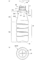
- (A) is a front view of the peeling container of the present embodiment, and (b) is a bottom view of the peeling container of the present embodiment. It is a vertical sectional view of the peeling container of this embodiment. It is a figure which shows typically the structure of the blow molding apparatus of this embodiment. It is a figure which shows the manufacturing process of the preform of this embodiment.
- (A) is a diagram showing the vicinity of the bottom of the first layer in the first injection molding portion, and (b) is a diagram showing the vicinity of the bottom of the preform in the second injection molding portion. It is a perspective view which shows the structural example of the 2nd cavity type of the 1st injection molding part.
- FIG. 1 is a vertical cross-sectional view of the preform 10 of the present embodiment.
- the overall shape of the preform 10 is a bottomed cylindrical shape with one end open and the other end closed.
- the preform 10 includes a body portion 14 formed in a cylindrical shape, a bottom portion 15 that closes the other end side of the body portion 14, and a neck portion 13 formed in an opening on one end side of the body portion 14.
- the preform 10 has a two-layer structure in which a second layer (inner layer) 12 is laminated inside the first layer (outer layer) 11.
- the first layer 11 and the second layer 12 are formed of different thermoplastic resin materials by two-step injection molding as described later.
- the first layer 11 is made of a synthetic resin having excellent moldability and transparency.
- the second layer 12 is made of a synthetic resin having properties (for example, moisture barrier property, gas barrier property, heat resistance, chemical resistance) capable of stably storing the contents of the container and suppressing deterioration (oxidation). Will be done.
- the resin material of the first layer 11 a material having a melting point higher than that of the resin material of the second layer 12 is selected.
- the resin material of the first layer 11 is also referred to as a first resin material
- the resin material of the second layer 12 is also referred to as a second resin material.
- the combination of the first resin material and the second resin material can be appropriately selected according to the specifications of the release container.
- Specific types of materials include, for example, PET (polyethylene terephthalate), PEN (polyethylene naphthalate), PCTA (polycyclohexanedimethylene terephthalate), Tritan (Tritan (registered trademark): copolyester manufactured by Eastman Chemical Co., Ltd.).
- PP polyethylene
- PE polyethylene
- PC polyethylene
- PES polyyester sulfone
- PPSU polyphenyl sulfone
- PS polyyester
- COP / COC cyclic olefin polymer
- PMMA polymethacrylic acid
- Methyl: acrylic acrylic
- PLA polylactic acid
- the first resin material is PET (polyethylene terephthalate), and the second resin material is PP (polypropylene).
- the melting point of PP is about 160 to 170 ° C.
- the melting point of PET is higher than the melting point of PP, which is about 245 to 260 ° C.
- the ratio (t1 / t2) of the thickness t1 of the first layer 11 to the thickness t2 of the second layer 12 is preferably 1.5 or more.
- the thickness ratio is preferably 3.0 or less from the viewpoint of ensuring the transparency of the peeling container to be molded.
- an opening 16 is formed at the center of the bottom portion of the first layer 11 so as to penetrate the first layer 11.
- the opening 16 of the first layer 11 is closed from the inside by the second layer 12.
- the bottom 15 of the preform 10 is formed with a recess 17 for forming an air introduction hole in the peeling container.
- the recess 17 has, for example, a circular cross section and is formed at least at one location with a radial interval from the center of the bottom 15 of the preform 10, but a plurality of recesses 17 are formed along the circumferential direction. You may be.
- the depth of the recess 17 in the thickness direction of the container is set so that at least the recess 17 penetrates the first layer 11 and the surface of the second layer 12 is exposed in the recess 17.
- the recess 17 formed in the preform 10 having a two-layer structure may be referred to as a second recess to distinguish it from the recess (described later) formed only in the first layer 11.
- the cross section of the recess 17 may be a circular shape, an elliptical shape, a polygonal shape, a slit shape, or a shape in which these are combined.
- FIGS. 2 and 3 are a front view and a bottom view of the peeling container 20 of the present embodiment.
- FIG. 3 is a vertical cross-sectional view of the peeling container 20 of the present embodiment.
- the peeling container 20 is a bottle-shaped resin container obtained by stretching and blow molding the preform 10, and contains, for example, a seasoning liquid such as soy sauce.
- the peeling container 20 may be used to store other contents such as a cosmetic liquid for cosmetics.
- the container is sealed by attaching the nozzle head 60, which is an example of the pump member, to the neck portion 21 described later of the peeling container 20 in an airtight state.
- the nozzle head 60 discharges a predetermined amount of the contents of the container from the nozzle in response to the operation of pushing down the top.
- the peeling container 20 has a two-layer structure in which a bag-shaped second layer 12 is laminated inside the first layer 11 as in the preform 10.
- the ratio of the thickness t11 of the first layer 11 to the thickness t12 of the second layer 12 (t11 / t12) is the ratio of the thickness of the preform 10 to the body portion 14 of the preform 10 (t1 /. It is almost the same as t2).
- the peeling container 20 has a neck portion 21 having an opening at the upper end, a cylindrical body portion 22 continuous from the neck portion 21, and a bottom portion 23 continuous from the body portion 22.
- the body portion 22 has a shoulder portion 22a whose one end is connected to the neck portion 21 and expands radially toward the other end, a main body portion 22c whose other end is connected to the bottom portion 23, and the other end and the main body portion of the shoulder portion 22a. It includes a constricted portion 22b that is connected to one end of each of the 22c and connects the shoulder portion 22a and the main body portion 22c.
- the cross section of the peeling container 20 has a substantially circular shape at any position in the axial direction.
- the constricted portion 22b has a first curved surface portion 22b1 whose diameter is reduced from the outer peripheral edge of the shoulder portion 22a toward the lower side (direction in which the bottom portion is located) and an upper side (direction in which the neck portion is located) from one end of the main body portion 22c. It has a second curved surface portion 22b2 whose diameter is reduced toward the surface.
- the diameter of the constricted bottom 22b3, which is connected to the first curved surface portion 22b1 and the second curved surface portion 22b2 and has the smallest diameter in the constricted portion 22b, is the diameter of the other end of the shoulder portion 22a (the outer peripheral edge of the shoulder portion 22a). And smaller than the diameter of the main body 22c.
- the directional dimensions and the like are set so that the nozzle head 60 can be operated by holding the container with one hand.
- the peeling container 20 is configured so that the thumb and the middle finger are supported by being attached to the first curved surface portion 22b1 of the constricted portion 22, and the nozzle head 60 can be pressed with the index finger.
- the radius of curvature (R value) of the first curved surface portion 22b1 is smaller than the radius of curvature of the second curved surface portion 22b2. That is, the constricted portion 22b has a shape in which the first curved surface portion 22b1 close to the shoulder portion 22a is greatly curved, and the second curved surface portion 22b2 close to the main body portion 22c is curved more gently than the first curved surface portion 22b1. ing.
- the finger supporting the constricted portion 22 does not slip and is easily caught by the shoulder portion 22a, so that it becomes easier to support the container.
- the thumb, the middle finger, the ring finger and the like can be easily fitted to the recessed portion 22b, so that the container can be supported and operated with one hand more easily.
- the diameter ( ⁇ 1) of the outer peripheral edge of the shoulder portion 22a is 40 mm or more and 55 mm or less
- the axial length (L1) from the position of the outer peripheral edge of the shoulder portion 22a to the position of the constricted bottom portion of the constricted portion 22b is 12 mm. It is 25 mm or more and 25 mm or less.
- the ratio ( ⁇ 2 / ⁇ 1) of the diameter ( ⁇ 2) of the constricted bottom of the constricted portion 22b to the diameter ( ⁇ 1) of the outer peripheral edge of the shoulder portion 22a is in the range of 0.80 or more and 0.93 or less.
- the diameter ⁇ 2 of the constricted bottom 22b3 of the constricted portion 22b supported by the thumb and the middle finger is the ratio of the diameter ⁇ 1 of the outer peripheral edge of the shoulder portion 22a to the diameter ⁇ 1 of the outer peripheral edge of the shoulder portion 22a to the diameter ⁇ 2 of the constricted bottom 22b3 ( ⁇ 2). It can be specified from / ⁇ 1). If the diameter ⁇ 2 of the bottom of the constriction is large, it becomes difficult to support the container by sandwiching it between the thumb and the middle finger, which reduces the usability of the container.
- the axial length L1 from the position of the outer peripheral edge of the shoulder portion 22a to the position of the constricted bottom portion 22b3 of the constricted portion 22b is 12 mm or more. It is ergonomically preferable to have a range of 25 mm or less.
- the smaller the value the easier it is for the finger attached to the bottom of the constriction to get caught on the shoulder 22a.
- the ratio of ⁇ 2 / ⁇ 1 is reduced and the shoulder portion 22a protrudes greatly from the bottom of the constriction, it becomes difficult to shape the peeling container 20 at the time of blow molding, and the peeling container 20 is used. At this time, the inner layer (second layer 12) may be difficult to peel off from the outer layer (first layer 11) at the overhanging portion of the shoulder portion 22a.
- the axial spacing L2 is preferably 65 mm or less.
- the body 14 and the bottom 15 of the preform 10 are expanded by the stretching blow, so that the body 22 and the bottom 23 of the peeling container 20 are shaped. Further, during the stretching blow, the recess 17 of the preform 10 is stretched, so that the bottom 23 of the peeling container 20 has an air introduction hole penetrating the first layer 11 as shown in FIG. 2 (b). At least one of 24 is formed.
- the air introduction hole 24 preferably has a diameter of 0.5 mm or more and a circular or elliptical shape. Further, it is desirable that a plurality (for example, four or more) of air introduction holes 24 are formed in the bottom portion 23 of the peeling container 20. Further, it is preferable that the plurality of air introduction holes 24 are arranged radially with reference to the center (gate portion) of the bottom portion 23 of the peeling container 20. When forming a plurality of air introduction holes 24, each air introduction hole 24 may be formed so as to be point-symmetrical with respect to the center of the bottom portion 23, or may be arranged so as to be deviated from the point-symmetrical position. good. Note that FIG. 2B shows an example in which the four air introduction holes 24 are arranged point-symmetrically.
- the contents are filled in the space inside the second layer 12.
- the contents when the contents are discharged from the second layer 12 by pressing the nozzle head 60, air gradually flows in between the first layer 11 and the second layer 12 from the air introduction hole 24, and the first The layer 11 and the second layer 12 are peeled off.
- the volume occupied by the contents in the container can be replaced with air without exposing the contents of the second layer 12 to air, and the contents filled in the second layer 12 can be discharged to the outside of the container.
- an opening 25 (non-laminated portion, single layer portion) penetrating the first layer 11 is formed as in the preform 10.
- the opening 25 is filled with the material of the second layer 12 so as to close the opening 25, and the second layer 12 is exposed to the outside of the first layer 11 in the vicinity of the opening 25 of the bottom 23 of the peeling container 20. It has become.
- the second layer 12 is partially fixed to the first layer 11 by exposing the second layer 12 to the outside of the first layer 11 in the opening 25 of the peeling container 20, and the second layer 12 with respect to the first layer 11 Misalignment is suppressed.
- FIG. 4 is a diagram schematically showing the configuration of the blow molding apparatus 30 of the present embodiment.
- the blow molding device 30 of the present embodiment is an example of a manufacturing device for the peeling container 20, and the peeling container 20 is made by utilizing the heat possessed (internal heat amount) at the time of injection molding without cooling the preform 10 to room temperature.
- a hot parison method also called a one-stage method for blow molding is adopted.
- the blow molding apparatus 30 conveys the first injection molding unit 31, the first temperature adjustment unit 32, the second injection molding unit 33, the second temperature adjustment unit 34, the blow molding unit 35, the take-out unit 36, and the like. It includes a mechanism 37.
- the first injection molding unit 31, the first temperature adjustment unit 32, the second injection molding unit 33, the second temperature adjustment unit 34, the blow molding unit 35, and the take-out unit 36 have the same predetermined angle (for example, the same predetermined angle) about the transport mechanism 37. It is arranged at a position rotated by 60 degrees).
- the blow molding apparatus 30 may be configured to omit the first temperature adjusting unit 32 (in this case, each molding station is arranged at a position rotated by 72 degrees around the transfer mechanism 37). Further, the first injection molding unit 31 and the second injection molding unit 33 are provided with a core type elevating mechanism (not shown) above the transport mechanism 37.
- the transfer mechanism 37 includes a rotating plate (transfer plate) 37a that rotates about an axis in the direction perpendicular to the paper surface of FIG. On the rotating plate 37a, one or more neck molds 37b (not shown in FIG. 4) holding the neck portion 13 of the preform 10 (or the neck portion 21 of the peeling container 20) are arranged at predetermined angles.
- the transport mechanism 37 rotates the rotary plate 37a to adjust the preform 10 (or the peeling container 20) held by the neck mold 37b to the first injection molding unit 31, the second injection molding unit 33, and the second temperature adjustment.
- the section 34, the blow molding section 35, and the take-out section 36 are conveyed in this order.
- the transport mechanism 37 can also raise and lower the rotary plate 37a, and also performs operations related to mold closing and mold opening (release) in the first injection molding unit 31 and the second injection molding unit 33.
- the first injection molding unit 31 includes a cavity mold 40, a core mold 41, and a hot runner mold 42, and cooperates with a neck mold 37b that is conveyed during molding to manufacture the first layer 11 of the preform 10.
- the cavity type 40 is composed of a first cavity type 40A on the opening side (upper side) and a second cavity type 40B on the bottom surface side (lower side).
- a first injection device 38 that supplies a first resin material to the hot runner mold 42 is connected to the first injection molding unit 31.
- the cavity type 40 and the hot runner type 42 are fixed to the machine base of the blow molding apparatus 30 in an integrated state.
- the core type 41 is fixed to the core type elevating mechanism.
- FIG. 5 (a) and 5 (b) show a first injection molding unit 31 for molding the first layer 11 of the preform 10 of the present embodiment.
- FIG. 6A is a diagram showing the vicinity of the bottom of the first layer 11 in the first injection molding unit 31.
- FIG. 7 is a perspective view showing a configuration example of the cavity type 40 (second cavity type 40B) of the first injection molding unit 31.
- the cavity type 40 defines (defines) the shape of the outer circumference of the first layer 11.
- the first cavity mold 40A is a mold facing the opening side of the cavity mold 40 (the side that comes into contact with the neck mold 37b when the mold is closed), and defines the shape of the outer periphery of the body of the first layer 11.
- the second cavity mold 40B is a mold facing the bottom surface side (the side that comes into contact with the hot runner mold 42) of the cavity mold 40, and defines the shape of the outer periphery of the bottom portion of the first layer 11.
- the second cavity type 40B further includes a gate portion 40Ba that guides the resin material from the hot runner type 42 to the cavity surface.
- the hot runner type 42 has a resin supply unit 42a that introduces the first resin material plasticized (melted) by the first injection device 38 into the second cavity type 40B.
- the core mold 41 is a mold that defines the shape of the inner peripheral side of the first layer 11, and is inserted into the inner peripheral side of the cavity mold 40 from above.
- the neck mold 37b conveyed at the time of molding defines the outer shape of the neck portion 13 of the preform 10 (first layer 11).
- the cavity mold 40 and the core mold 41 and the neck mold 37b of the transport mechanism 37 are molded and closed to form the first layer.
- Form 11 mold spaces are formed. Then, by pouring the first resin material from the bottom of the mold space through the hot runner mold 42, the first layer 11 of the preform 10 is manufactured in the first injection molding portion 31.
- a columnar (or tapered columnar or prismatic) first protrusion 44 is provided at a predetermined position. ing. As shown in FIG. 7A, at least one of the first protrusions 44 is arranged at intervals in the radial direction from the center of the bottom where the resin supply portion 42a is located. As shown in FIG. 6A, the protrusion amount h1 of the first protrusion 44 with respect to the cavity reference surface of the second cavity type 40B (the cavity surface that defines the shape of the lower end side of the bottom outer peripheral surface of the first layer 11). Is about the same size as the thickness of the first layer 11.
- the tip of the first protrusion 44 faces the surface of the core mold 41 (arranged in the vicinity of the surface of the core mold 41).
- the first protrusion 44 forms a circular recess 11a in the first layer 11 at a position corresponding to the recess 17 of the preform 10.
- the recess 11a of the first layer 11 may penetrate the first layer 11 or may have a thin film formed between the core mold 41 and the first protrusion 44.
- the recess 11a of the first layer 11 formed by the first injection molding portion 31 is also referred to as a first recess.
- the resin supply portion 42a of the hot runner type 42 has a rod-shaped member that opens and closes a valve pin 43 (resin supply portion 42a) that can move in the axial direction to a position close to the core mold 41. ) Is provided.
- the valve pin 43 is housed inside the hot runner mold 42 until the first resin material is filled in the mold space, and after the first resin material is filled in the mold space, the end of the gate portion 40Ba on the cavity side is open. It protrudes to a position closer to the core mold 41.
- a thin film portion 18 having a thickness thinner than the peripheral portion of the resin material can be formed in the center of the bottom portion of the first layer 11.
- the neck mold 37b of the transport mechanism 37 is not opened and the first layer 11 of the preform 10 is held and conveyed as it is.
- the number of preforms 10 simultaneously molded by the first injection molding unit 31 that is, the number of peeling containers 20 that can be simultaneously molded by the blow molding apparatus 30) can be appropriately set.
- the first temperature adjusting unit 32 adjusts the temperature of a temperature adjusting mold (a heating pot or a temperature adjusting pot (temperature adjusting pot) for adjusting the temperature of the first layer 11 from the outside) and the first layer 11 from the inside (not shown). It is equipped with a heating rod, a temperature control rod (temperature control rod), or an air introduction rod).
- the first temperature adjusting unit 32 cools (or heats) the first layer 11 which is in a high temperature state after injection molding by accommodating it in a temperature adjusting mold kept at a predetermined temperature.
- the first temperature adjusting unit 32 also has a function of adjusting the temperature distribution of the first layer 11 to a predetermined state before being conveyed to the second injection molding unit 33.
- the second injection molding unit 33 includes a cavity mold 50, a core mold 51, and a hot runner mold 52, and cooperates with a neck mold 37b conveyed at the time of molding to provide a second layer 12 on the inner peripheral side of the first layer 11. Injection molding.
- the cavity type 50 is composed of a first cavity type 50A on the opening side (upper side) and a second cavity type 50B on the bottom surface side (lower side).
- a second injection device 39 that supplies a second resin material to the hot runner mold 52 is connected to the second injection molding unit 33.
- FIG. 5C shows a second injection molding unit 33 that molds the second layer 12 of the preform 10.
- FIG. 6B is a diagram showing the vicinity of the bottom of the preform 10 in the second injection molding unit 33.
- the cavity mold 50 is a mold for accommodating the first layer 11.
- the first cavity mold 50A is a mold facing the opening side of the cavity mold 50 and accommodates the body portion of the first layer 11.
- the second cavity mold 50B is a mold facing the bottom surface side of the cavity mold 50, and accommodates the bottom portion of the first layer 11.
- the second cavity type 50B further includes a gate portion 50Ba that guides the resin material from the hot runner type 52 to the cavity surface.
- the hot runner type 52 has a resin supply unit 52a for introducing a second resin material plasticized (melted) by the second injection device 39.
- the core mold 51 is a mold that defines the shape of the inner peripheral side of the second layer 12, and is inserted into the inner peripheral side of the cavity mold 50 from above.
- the hot runner type 52 may have a structure having a valve pin like the hot runner type 42. However, the position of the valve pin when closing the second resin material is set to a position that does not protrude from the opening end on the cavity side of the gate portion 50Ba.
- the second injection molding unit 33 accommodates the first layer 11 of the preform 10 injection-molded by the first injection molding unit 31.
- the second injection molding portion 33 When the second injection molding portion 33 is closed, a mold space is formed between the inner peripheral side of the first layer 11 and the surface of the core mold 51.
- the second layer 12 was laminated on the inner peripheral side of the first layer 11 by pouring the second resin material from the bottom of the mold space through the hot runner mold 52.
- the preform 10 is formed.
- a preform is formed at a predetermined position corresponding to the first protrusion 44 of the first injection molding portion 31.
- a second protrusion 54 such as a columnar shape corresponding to the shape of the recess 17 of 10 is provided. The second protrusion 54 is inserted into the recess 11a of the first layer 11 when the first layer 11 is housed in the second injection molding portion 33.
- the basic configuration of the protrusions and the like in the second cavity mold 50B is substantially the same as that of the second cavity mold 40B of the first injection molding portion 31.
- the second protrusion 54 from the cavity reference surface of the second cavity type 50B (the cavity surface that abuts on the lower end side region of the bottom outer peripheral surface of the first layer 11).
- the protrusion amount h2 of is larger than the thickness of the first layer 11. That is, the protrusion amount h2 of the second protrusion 54 is larger than the protrusion amount h1 of the first protrusion 44 (h2> h1). Therefore, when the second injection molding portion 33 is closed, the tip of the second protrusion 54 penetrates the recess 11a of the first layer 11 and projects to the inner peripheral side of the first layer 11.
- the protrusion amount h2 of the second protrusion 54 is set to be smaller than the thickness of the preform 10. That is, in the injection molding by the second injection molding portion 33, the second resin material flows between the core mold 51 and the second protrusion 54, so that the second protrusion 54 penetrates the second layer 12. No holes are formed.
- the second temperature adjusting unit 34 adjusts the temperature of a mold unit (heating pot or temperature adjusting pot (temperature adjusting pot) for adjusting the temperature of the preform 20 from the outside) and the preform 20 from the inside (not shown). It is equipped with a heating rod, a temperature control rod (temperature control rod), or an air introduction rod).
- the second temperature adjusting unit 34 accommodates the preform 10 conveyed from the second injection molding unit 33 in a mold unit kept at a predetermined temperature to equalize the temperature and remove the unbalanced temperature of the preform 10. The temperature is adjusted to a temperature suitable for the final blow (for example, about 90 ° C to 105 ° C).
- the second temperature adjusting unit 34 also has a function of cooling the preform 10 in a high temperature state after injection molding.
- the blow molding unit 35 blow-molds the preform 10 whose temperature has been adjusted by the temperature adjusting unit 33 to manufacture the peeling container 20.
- the blow molding unit 35 includes a blow cavity type, which is a pair of split molds corresponding to the shape of the release container 20, a bottom type, a drawing rod, and an air introduction member (all not shown).
- the blow molding unit 35 blow molds while stretching the preform 10. As a result, the preform 10 is shaped into a blow cavity type shape, and the peeling container 20 can be manufactured.
- the take-out unit 36 is configured to open the neck portion 21 of the release container 20 manufactured by the blow molding unit 35 from the neck mold 37b and take out the release container 20 to the outside of the blow molding apparatus 30.
- FIG. 8 is a flowchart showing the process of the manufacturing method of the peeling container 20.
- Step S101 First injection molding step
- the first resin material from the first injection device 38 is placed in the mold space formed by the cavity mold 40, the core mold 41, and the neck mold 37b. Is injected, and the first layer 11 of the preform 10 is molded. At this time, the first protrusion 44 forms a recess 11a at the bottom of the first layer 11.
- the first injection molding section 31 is opened and the first layer is released.
- the rotating plate 37a of the transport mechanism 37 rotates by a predetermined angle, and the first layer 11 of the preform 10 held by the neck mold 37b retains heat during injection molding. It is conveyed to the first temperature adjusting unit 32 in a state of being contained.
- Step S102 First temperature adjustment step
- the first layer 11 of the preform 10 is housed in the temperature adjusting mold, and the cooling of the first layer 11 and the adjustment of the temperature distribution (leveling and removing uneven temperature) are performed. Will be done.
- the first temperature adjustment step may be omitted.
- the rotating plate 37a of the transport mechanism 37 rotates by a predetermined angle, and the temperature-adjusted first layer 11 held by the neck mold 37b is the second injection molding portion. It is transported to 33.
- Step S103 Second injection molding step
- the first layer 11 of the preform 10 is housed in the second injection molding unit 33, and the injection molding of the second layer 12 is performed.
- a mold space is provided between the inner peripheral side of the first layer 11 and the surface of the core mold 51 facing the inner circumference of the first layer 11.
- the formed mold space is filled with a second resin material from the hot runner mold 52.
- the thin film portion 18 is formed at the bottom of the first layer 11, the thin film portion 18 is broken by the injection pressure of the second resin material to form an opening 16 at the bottom, and the opening 16 is formed from the above opening 16.
- the second resin material is guided to the inner peripheral side of the first layer 11.
- the temperature of the second resin material filled in the second injection molding unit 33 is set to a temperature lower than the melting point of the first resin material. Further, the surface temperature of the first layer 11 when the second resin material is filled in the second injection molding unit 33 is cooled to a temperature equal to or lower than the melting point of the second resin material.
- the cavity mold 50 faces the outer peripheral side of the first layer 11, and the shape of the first layer 11 is held from the outer peripheral side by the cavity mold 50. Therefore, even if the second resin material comes into contact with the first layer 11, the thermal deformation of the first layer 11 can be suppressed.
- the recess 17 of the preform 10 is closed with the second resin material. There is no. Further, since the tip of the second protrusion 54 in the second injection molding portion 33 projects to the inner peripheral side of the first layer, the recess 17 of the preform 10 formed by the second protrusion 54 is the first. The shape is such that the surface of the second layer 12 is exposed in the recess 17 through the layer 11.
- the preform 10 in which the second layer 12 is laminated on the inner peripheral side of the first layer 11 is manufactured by the first injection molding step and the second injection molding step.
- the rotating plate 37a of the transport mechanism 37 rotates by a predetermined angle, and the preform 10 held in the neck mold 37b contains the heat retained during injection molding. Is conveyed to the second temperature adjusting unit 34.
- Step S104 Second temperature adjustment step
- the preform 10 is housed in the temperature adjusting mold unit, and the temperature is adjusted so that the temperature of the preform 10 approaches the temperature suitable for the final blow.
- the rotating plate 37a of the transport mechanism 37 rotates by a predetermined angle, and the temperature-adjusted preform 10 held in the neck mold 37b is transported to the blow molding unit 35.
- Step S105 Blow molding step
- the blow molding unit 35 performs blow molding of the release container 20.
- the blow cavity mold is closed, the preform 10 is housed in the mold space, and the air introduction member (blow core) is lowered, so that the air introduction member is brought into contact with the neck portion 13 of the preform 10.
- the drawing rod is lowered to suppress the bottom portion 15 of the preform 10 from the inner surface, and the preform 10 is stretched on the horizontal axis by supplying blow air from the air introduction member while stretching the vertical axis as necessary. ..
- the preform 10 is bulged and shaped so as to be in close contact with the blow cavity type mold space, and is blow molded into the release container 20.
- Step S106 Container removal step
- the blow cavity mold is opened.
- the release container 20 can be moved from the blow molding unit 35.
- the rotating plate 37a of the transport mechanism 37 rotates by a predetermined angle, and the release container 20 is transported to the take-out unit 36.
- the neck portion 21 of the peeling container 20 is released from the neck mold 37b, and the peeling container 20 is taken out to the outside of the blow molding apparatus 30.
- the waiting times of the first injection molding step, the first temperature adjusting step, the second injection molding step, the second temperature adjusting step, the blow molding step, and the container taking-out step are all the same length. Become. Similarly, the transport time between each step is the same length.
- the first layer 11 (outer layer) of the preform 10 is molded in the first injection molding step, and the second layer 11 is formed inside the first layer 11 from the opening 16 of the first layer 11 in the second injection molding step.
- the layer 12 (inner layer) is injection-molded to produce a preform 10 having a two-layer structure.
- the outer layer can be formed first with a resin material having a high melting point, and then the inner layer can be formed with a resin material having a lower melting point than the outer layer.
- the preform 10 having a two-layer structure suitable for the specifications of the peeling container 20 can be manufactured by continuously performing injection molding of the inner layer while the outer layer has the heat retained at the time of injection molding.
- the preform 10 having a two-layer structure is released in a state where both the outer layer and the inner layer have the heat retained during injection molding. Therefore, when the peeling container 20 is manufactured by the hot parison type blow molding method. A suitable preform 10 can be obtained.
- the preform 10 having the above-mentioned two-layer structure is stretch-blow molded to produce the peeling container 20 in a state of having the heat retained at the time of injection molding. Therefore, in the present embodiment, the peeling container 20 having excellent aesthetic appearance, physical strength, and the like can be manufactured by the hot parison type blow molding method. Compared with the cold parison type blow molding, in the present embodiment, the manufactured preform 10 does not need to be cooled to near room temperature, and the step of reheating the preform 10 is also unnecessary. Therefore, according to the present embodiment, a series of steps from injection molding of the preform 10 to blow molding of the peeling container 20 can be completed in a relatively short time, and the peeling container 20 can be manufactured in a shorter cycle.
- the recess 11a is formed in the first layer 11 by the first protrusion 44 in the first injection molding step. Then, in the second injection molding step, the recess 11a of the first layer 11 is made to penetrate the second protrusion 54 having a larger protrusion amount than the first protrusion 44, and the recess 17 is formed in the bottom 15 of the preform 10. do. As a result, in the peeling container 20, the air introduction hole 24 that penetrates the first layer 11 and reaches the surface of the second layer 12 can be reliably formed.
- FIG. 7B shows an example in which the first protrusions 44 are provided at two places in the second cavity type 40B of the first injection molding part 31.
- the two first protrusions 44 are arranged at positions symmetrical with respect to the central axis with an interval of 180 °.
- the number of the first protrusions 44 may be three or more. At that time, it is preferable that each of the first protrusions 44 is arranged in a point-symmetrical positional relationship with respect to the central axis.
Landscapes
- Engineering & Computer Science (AREA)
- Mechanical Engineering (AREA)
- Manufacturing & Machinery (AREA)
- Ceramic Engineering (AREA)
- Physics & Mathematics (AREA)
- Geometry (AREA)
- Blow-Moulding Or Thermoforming Of Plastics Or The Like (AREA)
Priority Applications (4)
| Application Number | Priority Date | Filing Date | Title |
|---|---|---|---|
| JP2022514085A JPWO2021206088A1 (zh) | 2020-04-06 | 2021-04-06 | |
| CN202180032815.6A CN115485203A (zh) | 2020-04-06 | 2021-04-06 | 剥离容器以及剥离容器的制造方法 |
| US17/916,679 US20230150710A1 (en) | 2020-04-06 | 2021-04-06 | Peeling container and method for manufacturing peeling container |
| EP21784591.6A EP4134317A4 (en) | 2020-04-06 | 2021-04-06 | TAKE-OFF CONTAINER AND METHOD FOR MANUFACTURING TAKE-OFF CONTAINER |
Applications Claiming Priority (4)
| Application Number | Priority Date | Filing Date | Title |
|---|---|---|---|
| JP2020-068177 | 2020-04-06 | ||
| JP2020068177 | 2020-04-06 | ||
| JP2020106297 | 2020-06-19 | ||
| JP2020-106297 | 2020-06-19 |
Publications (1)
| Publication Number | Publication Date |
|---|---|
| WO2021206088A1 true WO2021206088A1 (ja) | 2021-10-14 |
Family
ID=78023301
Family Applications (1)
| Application Number | Title | Priority Date | Filing Date |
|---|---|---|---|
| PCT/JP2021/014634 WO2021206088A1 (ja) | 2020-04-06 | 2021-04-06 | 剥離容器および剥離容器の製造方法 |
Country Status (5)
| Country | Link |
|---|---|
| US (1) | US20230150710A1 (zh) |
| EP (1) | EP4134317A4 (zh) |
| JP (1) | JPWO2021206088A1 (zh) |
| CN (1) | CN115485203A (zh) |
| WO (1) | WO2021206088A1 (zh) |
Citations (9)
| Publication number | Priority date | Publication date | Assignee | Title |
|---|---|---|---|---|
| JP2001114328A (ja) * | 1999-10-08 | 2001-04-24 | Taisei Kako Co Ltd | 積層剥離ボトル、並びに、ポンプ容器 |
| US6554146B1 (en) * | 2002-01-17 | 2003-04-29 | Owens-Brockway Plastic Products Inc. | Single serve plastic container and package incorporating same |
| JP2011011767A (ja) * | 2009-06-30 | 2011-01-20 | Yoshino Kogyosho Co Ltd | 合成樹脂製壜体 |
| JP5267901B2 (ja) | 2007-06-29 | 2013-08-21 | 株式会社吉野工業所 | ダイレクトブロー成形法による合成樹脂製二重容器 |
| JP2015081096A (ja) * | 2013-10-21 | 2015-04-27 | 大日本印刷株式会社 | プラスチックボトル |
| JP2017154804A (ja) * | 2016-03-03 | 2017-09-07 | 大日本印刷株式会社 | プラスチックボトル、充填体、及び充填体の製造方法 |
| JP2018012511A (ja) * | 2016-07-19 | 2018-01-25 | キョーラク株式会社 | 積層剥離容器 |
| JP2018188183A (ja) * | 2017-04-28 | 2018-11-29 | 株式会社吉野工業所 | 二重容器 |
| JP2019116308A (ja) * | 2017-12-27 | 2019-07-18 | キョーラク株式会社 | 積層剥離容器 |
Family Cites Families (1)
| Publication number | Priority date | Publication date | Assignee | Title |
|---|---|---|---|---|
| JP4357183B2 (ja) * | 2003-02-14 | 2009-11-04 | 大成化工株式会社 | 積層剥離ボトル及びその製造方法 |
-
2021
- 2021-04-06 JP JP2022514085A patent/JPWO2021206088A1/ja active Pending
- 2021-04-06 US US17/916,679 patent/US20230150710A1/en active Pending
- 2021-04-06 CN CN202180032815.6A patent/CN115485203A/zh active Pending
- 2021-04-06 EP EP21784591.6A patent/EP4134317A4/en active Pending
- 2021-04-06 WO PCT/JP2021/014634 patent/WO2021206088A1/ja unknown
Patent Citations (9)
| Publication number | Priority date | Publication date | Assignee | Title |
|---|---|---|---|---|
| JP2001114328A (ja) * | 1999-10-08 | 2001-04-24 | Taisei Kako Co Ltd | 積層剥離ボトル、並びに、ポンプ容器 |
| US6554146B1 (en) * | 2002-01-17 | 2003-04-29 | Owens-Brockway Plastic Products Inc. | Single serve plastic container and package incorporating same |
| JP5267901B2 (ja) | 2007-06-29 | 2013-08-21 | 株式会社吉野工業所 | ダイレクトブロー成形法による合成樹脂製二重容器 |
| JP2011011767A (ja) * | 2009-06-30 | 2011-01-20 | Yoshino Kogyosho Co Ltd | 合成樹脂製壜体 |
| JP2015081096A (ja) * | 2013-10-21 | 2015-04-27 | 大日本印刷株式会社 | プラスチックボトル |
| JP2017154804A (ja) * | 2016-03-03 | 2017-09-07 | 大日本印刷株式会社 | プラスチックボトル、充填体、及び充填体の製造方法 |
| JP2018012511A (ja) * | 2016-07-19 | 2018-01-25 | キョーラク株式会社 | 積層剥離容器 |
| JP2018188183A (ja) * | 2017-04-28 | 2018-11-29 | 株式会社吉野工業所 | 二重容器 |
| JP2019116308A (ja) * | 2017-12-27 | 2019-07-18 | キョーラク株式会社 | 積層剥離容器 |
Non-Patent Citations (1)
| Title |
|---|
| See also references of EP4134317A4 |
Also Published As
| Publication number | Publication date |
|---|---|
| JPWO2021206088A1 (zh) | 2021-10-14 |
| EP4134317A4 (en) | 2023-12-27 |
| EP4134317A1 (en) | 2023-02-15 |
| CN115485203A (zh) | 2022-12-16 |
| US20230150710A1 (en) | 2023-05-18 |
Similar Documents
| Publication | Publication Date | Title |
|---|---|---|
| WO2021206082A1 (ja) | 剥離容器の製造方法および製造装置 | |
| US20090206524A1 (en) | Moulding Apparatus and Method | |
| JP7457077B2 (ja) | 首曲がり容器の製造方法、温度調整用金型、ブロー成形装置およびブロー成形方法 | |
| WO2008063726A2 (en) | Injection blow molding process and article | |
| WO2021206088A1 (ja) | 剥離容器および剥離容器の製造方法 | |
| WO2021206083A1 (ja) | 剥離容器の製造方法および製造装置 | |
| WO2022118840A1 (ja) | 樹脂製容器の製造方法および製造装置 | |
| WO2022030461A1 (ja) | 樹脂製容器の製造方法、金型ユニットおよびブロー成形装置 | |
| US20220339842A1 (en) | Method for producing delamination container and apparatus for producing delamination container | |
| WO2023171603A1 (ja) | 樹脂製容器の製造方法、温度調整用金型ユニットおよび樹脂製容器の製造装置 | |
| WO2020262595A1 (ja) | 樹脂製成形品の製造装置、樹脂製成形品の製造方法、及び樹脂製成形品 | |
| WO2024101420A1 (ja) | 剥離容器、プリフォーム、剥離容器の製造方法および製造装置 | |
| WO2022196658A1 (ja) | 樹脂製容器の製造方法および製造装置 | |
| JP7183379B2 (ja) | 容器の金型および容器の製造方法 | |
| WO2022107788A1 (ja) | 樹脂製容器の製造方法および製造装置 | |
| WO2022059695A1 (ja) | 樹脂製容器の製造方法および製造装置 | |
| KR102260061B1 (ko) | 손잡이를 갖춘 페트병 제조방법과 이에 따른 제조장치 및 이에 의해 제조된 페트병 | |
| WO2023157863A1 (ja) | 温度調整用金型、温度調整方法および樹脂製容器の製造装置 | |
| JPWO2022118840A5 (zh) | ||
| KR20220124754A (ko) | 수지제 용기의 제조 방법, 제조 장치 및 금형 유닛 | |
| JP2008007119A (ja) | 複合容器及びその製造方法 |
Legal Events
| Date | Code | Title | Description |
|---|---|---|---|
| 121 | Ep: the epo has been informed by wipo that ep was designated in this application |
Ref document number: 21784591 Country of ref document: EP Kind code of ref document: A1 |
|
| ENP | Entry into the national phase |
Ref document number: 2022514085 Country of ref document: JP Kind code of ref document: A |
|
| NENP | Non-entry into the national phase |
Ref country code: DE |
|
| ENP | Entry into the national phase |
Ref document number: 2021784591 Country of ref document: EP Effective date: 20221107 |