WO2021206088A1 - Peeling container and method for manufacturing peeling container - Google Patents
Peeling container and method for manufacturing peeling container Download PDFInfo
- Publication number
- WO2021206088A1 WO2021206088A1 PCT/JP2021/014634 JP2021014634W WO2021206088A1 WO 2021206088 A1 WO2021206088 A1 WO 2021206088A1 JP 2021014634 W JP2021014634 W JP 2021014634W WO 2021206088 A1 WO2021206088 A1 WO 2021206088A1
- Authority
- WO
- WIPO (PCT)
- Prior art keywords
- layer
- injection molding
- peeling container
- preform
- resin material
- Prior art date
Links
- 238000004519 manufacturing process Methods 0.000 title claims description 19
- 238000000034 method Methods 0.000 title claims description 10
- 229920005989 resin Polymers 0.000 claims abstract description 60
- 239000011347 resin Substances 0.000 claims abstract description 60
- 239000000463 material Substances 0.000 claims abstract description 56
- 230000002093 peripheral effect Effects 0.000 claims abstract description 44
- 230000004323 axial length Effects 0.000 claims abstract description 6
- 238000001746 injection moulding Methods 0.000 claims description 97
- 238000000071 blow moulding Methods 0.000 claims description 44
- 238000003825 pressing Methods 0.000 claims description 5
- 230000000717 retained effect Effects 0.000 claims description 5
- 238000010030 laminating Methods 0.000 claims 1
- 239000010410 layer Substances 0.000 description 168
- 210000003811 finger Anatomy 0.000 description 17
- 230000007723 transport mechanism Effects 0.000 description 13
- 238000002844 melting Methods 0.000 description 10
- 230000008018 melting Effects 0.000 description 10
- 238000000465 moulding Methods 0.000 description 9
- 238000002347 injection Methods 0.000 description 8
- 239000007924 injection Substances 0.000 description 8
- 210000003813 thumb Anatomy 0.000 description 8
- -1 polyethylene terephthalate Polymers 0.000 description 6
- 239000010409 thin film Substances 0.000 description 6
- 239000004743 Polypropylene Substances 0.000 description 5
- 238000010586 diagram Methods 0.000 description 5
- 230000007246 mechanism Effects 0.000 description 5
- 229920000139 polyethylene terephthalate Polymers 0.000 description 5
- 239000005020 polyethylene terephthalate Substances 0.000 description 5
- 239000002537 cosmetic Substances 0.000 description 4
- 238000010438 heat treatment Methods 0.000 description 4
- 239000007788 liquid Substances 0.000 description 4
- 239000004698 Polyethylene Substances 0.000 description 3
- 238000001816 cooling Methods 0.000 description 3
- 229920000728 polyester Polymers 0.000 description 3
- 238000012546 transfer Methods 0.000 description 3
- 229920000089 Cyclic olefin copolymer Polymers 0.000 description 2
- 229920000491 Polyphenylsulfone Polymers 0.000 description 2
- 230000004888 barrier function Effects 0.000 description 2
- 230000007547 defect Effects 0.000 description 2
- 238000009826 distribution Methods 0.000 description 2
- 230000003028 elevating effect Effects 0.000 description 2
- 235000011194 food seasoning agent Nutrition 0.000 description 2
- 230000000149 penetrating effect Effects 0.000 description 2
- 229920003207 poly(ethylene-2,6-naphthalate) Polymers 0.000 description 2
- 229920000747 poly(lactic acid) Polymers 0.000 description 2
- 229920000573 polyethylene Polymers 0.000 description 2
- 239000011112 polyethylene naphthalate Substances 0.000 description 2
- 239000004626 polylactic acid Substances 0.000 description 2
- 235000013555 soy sauce Nutrition 0.000 description 2
- 229920003002 synthetic resin Polymers 0.000 description 2
- 239000000057 synthetic resin Substances 0.000 description 2
- FDSYTWVNUJTPMA-UHFFFAOYSA-N 2-[3,9-bis(carboxymethyl)-3,6,9,15-tetrazabicyclo[9.3.1]pentadeca-1(15),11,13-trien-6-yl]acetic acid Chemical compound C1N(CC(O)=O)CCN(CC(=O)O)CCN(CC(O)=O)CC2=CC=CC1=N2 FDSYTWVNUJTPMA-UHFFFAOYSA-N 0.000 description 1
- 229920001634 Copolyester Polymers 0.000 description 1
- 229920002845 Poly(methacrylic acid) Polymers 0.000 description 1
- NIXOWILDQLNWCW-UHFFFAOYSA-N acrylic acid group Chemical group C(C=C)(=O)O NIXOWILDQLNWCW-UHFFFAOYSA-N 0.000 description 1
- 238000013459 approach Methods 0.000 description 1
- 238000006243 chemical reaction Methods 0.000 description 1
- 238000013461 design Methods 0.000 description 1
- 230000006866 deterioration Effects 0.000 description 1
- 238000007599 discharging Methods 0.000 description 1
- 230000000694 effects Effects 0.000 description 1
- 230000007613 environmental effect Effects 0.000 description 1
- 238000001125 extrusion Methods 0.000 description 1
- 125000002496 methyl group Chemical group [H]C([H])([H])* 0.000 description 1
- 238000012986 modification Methods 0.000 description 1
- 230000004048 modification Effects 0.000 description 1
- 230000003647 oxidation Effects 0.000 description 1
- 238000007254 oxidation reaction Methods 0.000 description 1
- 229920003229 poly(methyl methacrylate) Polymers 0.000 description 1
- 239000004926 polymethyl methacrylate Substances 0.000 description 1
- 229920001155 polypropylene Polymers 0.000 description 1
- 230000008569 process Effects 0.000 description 1
- 238000003303 reheating Methods 0.000 description 1
- 230000004044 response Effects 0.000 description 1
- 239000002356 single layer Substances 0.000 description 1
- 239000000126 substance Substances 0.000 description 1
- 150000003457 sulfones Chemical class 0.000 description 1
- KKEYFWRCBNTPAC-UHFFFAOYSA-L terephthalate(2-) Chemical compound [O-]C(=O)C1=CC=C(C([O-])=O)C=C1 KKEYFWRCBNTPAC-UHFFFAOYSA-L 0.000 description 1
- 229920005992 thermoplastic resin Polymers 0.000 description 1
Images


Classifications
-
- B—PERFORMING OPERATIONS; TRANSPORTING
- B65—CONVEYING; PACKING; STORING; HANDLING THIN OR FILAMENTARY MATERIAL
- B65D—CONTAINERS FOR STORAGE OR TRANSPORT OF ARTICLES OR MATERIALS, e.g. BAGS, BARRELS, BOTTLES, BOXES, CANS, CARTONS, CRATES, DRUMS, JARS, TANKS, HOPPERS, FORWARDING CONTAINERS; ACCESSORIES, CLOSURES, OR FITTINGS THEREFOR; PACKAGING ELEMENTS; PACKAGES
- B65D1/00—Containers having bodies formed in one piece, e.g. by casting metallic material, by moulding plastics, by blowing vitreous material, by throwing ceramic material, by moulding pulped fibrous material, by deep-drawing operations performed on sheet material
- B65D1/02—Bottles or similar containers with necks or like restricted apertures, designed for pouring contents
- B65D1/0207—Bottles or similar containers with necks or like restricted apertures, designed for pouring contents characterised by material, e.g. composition, physical features
- B65D1/0215—Bottles or similar containers with necks or like restricted apertures, designed for pouring contents characterised by material, e.g. composition, physical features multilayered
-
- B—PERFORMING OPERATIONS; TRANSPORTING
- B29—WORKING OF PLASTICS; WORKING OF SUBSTANCES IN A PLASTIC STATE IN GENERAL
- B29C—SHAPING OR JOINING OF PLASTICS; SHAPING OF MATERIAL IN A PLASTIC STATE, NOT OTHERWISE PROVIDED FOR; AFTER-TREATMENT OF THE SHAPED PRODUCTS, e.g. REPAIRING
- B29C45/00—Injection moulding, i.e. forcing the required volume of moulding material through a nozzle into a closed mould; Apparatus therefor
- B29C45/03—Injection moulding apparatus
- B29C45/04—Injection moulding apparatus using movable moulds or mould halves
- B29C45/06—Injection moulding apparatus using movable moulds or mould halves mounted on a turntable, i.e. on a rotating support having a rotating axis parallel to the mould opening, closing or clamping direction
-
- B—PERFORMING OPERATIONS; TRANSPORTING
- B29—WORKING OF PLASTICS; WORKING OF SUBSTANCES IN A PLASTIC STATE IN GENERAL
- B29C—SHAPING OR JOINING OF PLASTICS; SHAPING OF MATERIAL IN A PLASTIC STATE, NOT OTHERWISE PROVIDED FOR; AFTER-TREATMENT OF THE SHAPED PRODUCTS, e.g. REPAIRING
- B29C45/00—Injection moulding, i.e. forcing the required volume of moulding material through a nozzle into a closed mould; Apparatus therefor
- B29C45/16—Making multilayered or multicoloured articles
- B29C45/1635—Making multilayered or multicoloured articles using displaceable mould parts, e.g. retractable partition between adjacent mould cavities
-
- B—PERFORMING OPERATIONS; TRANSPORTING
- B29—WORKING OF PLASTICS; WORKING OF SUBSTANCES IN A PLASTIC STATE IN GENERAL
- B29C—SHAPING OR JOINING OF PLASTICS; SHAPING OF MATERIAL IN A PLASTIC STATE, NOT OTHERWISE PROVIDED FOR; AFTER-TREATMENT OF THE SHAPED PRODUCTS, e.g. REPAIRING
- B29C45/00—Injection moulding, i.e. forcing the required volume of moulding material through a nozzle into a closed mould; Apparatus therefor
- B29C45/17—Component parts, details or accessories; Auxiliary operations
- B29C45/26—Moulds
-
- B—PERFORMING OPERATIONS; TRANSPORTING
- B29—WORKING OF PLASTICS; WORKING OF SUBSTANCES IN A PLASTIC STATE IN GENERAL
- B29C—SHAPING OR JOINING OF PLASTICS; SHAPING OF MATERIAL IN A PLASTIC STATE, NOT OTHERWISE PROVIDED FOR; AFTER-TREATMENT OF THE SHAPED PRODUCTS, e.g. REPAIRING
- B29C49/00—Blow-moulding, i.e. blowing a preform or parison to a desired shape within a mould; Apparatus therefor
- B29C49/02—Combined blow-moulding and manufacture of the preform or the parison
- B29C49/06—Injection blow-moulding
- B29C49/061—Injection blow-moulding with parison holding means displaceable between injection and blow stations
- B29C49/062—Injection blow-moulding with parison holding means displaceable between injection and blow stations following an arcuate path, e.g. rotary or oscillating-type
-
- B—PERFORMING OPERATIONS; TRANSPORTING
- B29—WORKING OF PLASTICS; WORKING OF SUBSTANCES IN A PLASTIC STATE IN GENERAL
- B29C—SHAPING OR JOINING OF PLASTICS; SHAPING OF MATERIAL IN A PLASTIC STATE, NOT OTHERWISE PROVIDED FOR; AFTER-TREATMENT OF THE SHAPED PRODUCTS, e.g. REPAIRING
- B29C49/00—Blow-moulding, i.e. blowing a preform or parison to a desired shape within a mould; Apparatus therefor
- B29C49/071—Preforms or parisons characterised by their configuration, e.g. geometry, dimensions or physical properties
-
- B—PERFORMING OPERATIONS; TRANSPORTING
- B29—WORKING OF PLASTICS; WORKING OF SUBSTANCES IN A PLASTIC STATE IN GENERAL
- B29C—SHAPING OR JOINING OF PLASTICS; SHAPING OF MATERIAL IN A PLASTIC STATE, NOT OTHERWISE PROVIDED FOR; AFTER-TREATMENT OF THE SHAPED PRODUCTS, e.g. REPAIRING
- B29C49/00—Blow-moulding, i.e. blowing a preform or parison to a desired shape within a mould; Apparatus therefor
- B29C49/08—Biaxial stretching during blow-moulding
- B29C49/10—Biaxial stretching during blow-moulding using mechanical means for prestretching
- B29C49/12—Stretching rods
-
- B—PERFORMING OPERATIONS; TRANSPORTING
- B29—WORKING OF PLASTICS; WORKING OF SUBSTANCES IN A PLASTIC STATE IN GENERAL
- B29C—SHAPING OR JOINING OF PLASTICS; SHAPING OF MATERIAL IN A PLASTIC STATE, NOT OTHERWISE PROVIDED FOR; AFTER-TREATMENT OF THE SHAPED PRODUCTS, e.g. REPAIRING
- B29C49/00—Blow-moulding, i.e. blowing a preform or parison to a desired shape within a mould; Apparatus therefor
- B29C49/22—Blow-moulding, i.e. blowing a preform or parison to a desired shape within a mould; Apparatus therefor using multilayered preforms or parisons
-
- B—PERFORMING OPERATIONS; TRANSPORTING
- B65—CONVEYING; PACKING; STORING; HANDLING THIN OR FILAMENTARY MATERIAL
- B65D—CONTAINERS FOR STORAGE OR TRANSPORT OF ARTICLES OR MATERIALS, e.g. BAGS, BARRELS, BOTTLES, BOXES, CANS, CARTONS, CRATES, DRUMS, JARS, TANKS, HOPPERS, FORWARDING CONTAINERS; ACCESSORIES, CLOSURES, OR FITTINGS THEREFOR; PACKAGING ELEMENTS; PACKAGES
- B65D1/00—Containers having bodies formed in one piece, e.g. by casting metallic material, by moulding plastics, by blowing vitreous material, by throwing ceramic material, by moulding pulped fibrous material, by deep-drawing operations performed on sheet material
- B65D1/02—Bottles or similar containers with necks or like restricted apertures, designed for pouring contents
- B65D1/0223—Bottles or similar containers with necks or like restricted apertures, designed for pouring contents characterised by shape
-
- B—PERFORMING OPERATIONS; TRANSPORTING
- B65—CONVEYING; PACKING; STORING; HANDLING THIN OR FILAMENTARY MATERIAL
- B65D—CONTAINERS FOR STORAGE OR TRANSPORT OF ARTICLES OR MATERIALS, e.g. BAGS, BARRELS, BOTTLES, BOXES, CANS, CARTONS, CRATES, DRUMS, JARS, TANKS, HOPPERS, FORWARDING CONTAINERS; ACCESSORIES, CLOSURES, OR FITTINGS THEREFOR; PACKAGING ELEMENTS; PACKAGES
- B65D83/00—Containers or packages with special means for dispensing contents
- B65D83/0055—Containers or packages provided with a flexible bag or a deformable membrane or diaphragm for expelling the contents
-
- B—PERFORMING OPERATIONS; TRANSPORTING
- B29—WORKING OF PLASTICS; WORKING OF SUBSTANCES IN A PLASTIC STATE IN GENERAL
- B29C—SHAPING OR JOINING OF PLASTICS; SHAPING OF MATERIAL IN A PLASTIC STATE, NOT OTHERWISE PROVIDED FOR; AFTER-TREATMENT OF THE SHAPED PRODUCTS, e.g. REPAIRING
- B29C45/00—Injection moulding, i.e. forcing the required volume of moulding material through a nozzle into a closed mould; Apparatus therefor
- B29C45/16—Making multilayered or multicoloured articles
- B29C45/1635—Making multilayered or multicoloured articles using displaceable mould parts, e.g. retractable partition between adjacent mould cavities
- B29C2045/1637—Making multilayered or multicoloured articles using displaceable mould parts, e.g. retractable partition between adjacent mould cavities the first injected part and the movable mould part being movable together
-
- B—PERFORMING OPERATIONS; TRANSPORTING
- B29—WORKING OF PLASTICS; WORKING OF SUBSTANCES IN A PLASTIC STATE IN GENERAL
- B29C—SHAPING OR JOINING OF PLASTICS; SHAPING OF MATERIAL IN A PLASTIC STATE, NOT OTHERWISE PROVIDED FOR; AFTER-TREATMENT OF THE SHAPED PRODUCTS, e.g. REPAIRING
- B29C49/00—Blow-moulding, i.e. blowing a preform or parison to a desired shape within a mould; Apparatus therefor
- B29C49/02—Combined blow-moulding and manufacture of the preform or the parison
- B29C2049/023—Combined blow-moulding and manufacture of the preform or the parison using inherent heat of the preform, i.e. 1 step blow moulding
-
- B—PERFORMING OPERATIONS; TRANSPORTING
- B29—WORKING OF PLASTICS; WORKING OF SUBSTANCES IN A PLASTIC STATE IN GENERAL
- B29C—SHAPING OR JOINING OF PLASTICS; SHAPING OF MATERIAL IN A PLASTIC STATE, NOT OTHERWISE PROVIDED FOR; AFTER-TREATMENT OF THE SHAPED PRODUCTS, e.g. REPAIRING
- B29C2949/00—Indexing scheme relating to blow-moulding
- B29C2949/07—Preforms or parisons characterised by their configuration
- B29C2949/0715—Preforms or parisons characterised by their configuration the preform having one end closed
-
- B—PERFORMING OPERATIONS; TRANSPORTING
- B29—WORKING OF PLASTICS; WORKING OF SUBSTANCES IN A PLASTIC STATE IN GENERAL
- B29C—SHAPING OR JOINING OF PLASTICS; SHAPING OF MATERIAL IN A PLASTIC STATE, NOT OTHERWISE PROVIDED FOR; AFTER-TREATMENT OF THE SHAPED PRODUCTS, e.g. REPAIRING
- B29C2949/00—Indexing scheme relating to blow-moulding
- B29C2949/07—Preforms or parisons characterised by their configuration
- B29C2949/076—Preforms or parisons characterised by their configuration characterised by the shape
- B29C2949/0768—Preforms or parisons characterised by their configuration characterised by the shape characterised by the shape of specific parts of preform
- B29C2949/078—Preforms or parisons characterised by their configuration characterised by the shape characterised by the shape of specific parts of preform characterised by the bottom
- B29C2949/0781—Preforms or parisons characterised by their configuration characterised by the shape characterised by the shape of specific parts of preform characterised by the bottom characterised by the sprue, i.e. injection mark
-
- B—PERFORMING OPERATIONS; TRANSPORTING
- B29—WORKING OF PLASTICS; WORKING OF SUBSTANCES IN A PLASTIC STATE IN GENERAL
- B29C—SHAPING OR JOINING OF PLASTICS; SHAPING OF MATERIAL IN A PLASTIC STATE, NOT OTHERWISE PROVIDED FOR; AFTER-TREATMENT OF THE SHAPED PRODUCTS, e.g. REPAIRING
- B29C2949/00—Indexing scheme relating to blow-moulding
- B29C2949/30—Preforms or parisons made of several components
- B29C2949/3008—Preforms or parisons made of several components at neck portion
-
- B—PERFORMING OPERATIONS; TRANSPORTING
- B29—WORKING OF PLASTICS; WORKING OF SUBSTANCES IN A PLASTIC STATE IN GENERAL
- B29C—SHAPING OR JOINING OF PLASTICS; SHAPING OF MATERIAL IN A PLASTIC STATE, NOT OTHERWISE PROVIDED FOR; AFTER-TREATMENT OF THE SHAPED PRODUCTS, e.g. REPAIRING
- B29C2949/00—Indexing scheme relating to blow-moulding
- B29C2949/30—Preforms or parisons made of several components
- B29C2949/3012—Preforms or parisons made of several components at flange portion
-
- B—PERFORMING OPERATIONS; TRANSPORTING
- B29—WORKING OF PLASTICS; WORKING OF SUBSTANCES IN A PLASTIC STATE IN GENERAL
- B29C—SHAPING OR JOINING OF PLASTICS; SHAPING OF MATERIAL IN A PLASTIC STATE, NOT OTHERWISE PROVIDED FOR; AFTER-TREATMENT OF THE SHAPED PRODUCTS, e.g. REPAIRING
- B29C2949/00—Indexing scheme relating to blow-moulding
- B29C2949/30—Preforms or parisons made of several components
- B29C2949/3016—Preforms or parisons made of several components at body portion
-
- B—PERFORMING OPERATIONS; TRANSPORTING
- B29—WORKING OF PLASTICS; WORKING OF SUBSTANCES IN A PLASTIC STATE IN GENERAL
- B29C—SHAPING OR JOINING OF PLASTICS; SHAPING OF MATERIAL IN A PLASTIC STATE, NOT OTHERWISE PROVIDED FOR; AFTER-TREATMENT OF THE SHAPED PRODUCTS, e.g. REPAIRING
- B29C2949/00—Indexing scheme relating to blow-moulding
- B29C2949/30—Preforms or parisons made of several components
- B29C2949/302—Preforms or parisons made of several components at bottom portion
- B29C2949/3022—Preforms or parisons made of several components at bottom portion partially
-
- B—PERFORMING OPERATIONS; TRANSPORTING
- B29—WORKING OF PLASTICS; WORKING OF SUBSTANCES IN A PLASTIC STATE IN GENERAL
- B29C—SHAPING OR JOINING OF PLASTICS; SHAPING OF MATERIAL IN A PLASTIC STATE, NOT OTHERWISE PROVIDED FOR; AFTER-TREATMENT OF THE SHAPED PRODUCTS, e.g. REPAIRING
- B29C2949/00—Indexing scheme relating to blow-moulding
- B29C2949/30—Preforms or parisons made of several components
- B29C2949/3032—Preforms or parisons made of several components having components being injected
- B29C2949/3034—Preforms or parisons made of several components having components being injected having two or more components being injected
-
- B—PERFORMING OPERATIONS; TRANSPORTING
- B29—WORKING OF PLASTICS; WORKING OF SUBSTANCES IN A PLASTIC STATE IN GENERAL
- B29K—INDEXING SCHEME ASSOCIATED WITH SUBCLASSES B29B, B29C OR B29D, RELATING TO MOULDING MATERIALS OR TO MATERIALS FOR MOULDS, REINFORCEMENTS, FILLERS OR PREFORMED PARTS, e.g. INSERTS
- B29K2023/00—Use of polyalkenes or derivatives thereof as moulding material
- B29K2023/10—Polymers of propylene
- B29K2023/12—PP, i.e. polypropylene
-
- B—PERFORMING OPERATIONS; TRANSPORTING
- B29—WORKING OF PLASTICS; WORKING OF SUBSTANCES IN A PLASTIC STATE IN GENERAL
- B29K—INDEXING SCHEME ASSOCIATED WITH SUBCLASSES B29B, B29C OR B29D, RELATING TO MOULDING MATERIALS OR TO MATERIALS FOR MOULDS, REINFORCEMENTS, FILLERS OR PREFORMED PARTS, e.g. INSERTS
- B29K2067/00—Use of polyesters or derivatives thereof, as moulding material
- B29K2067/003—PET, i.e. poylethylene terephthalate
-
- B—PERFORMING OPERATIONS; TRANSPORTING
- B29—WORKING OF PLASTICS; WORKING OF SUBSTANCES IN A PLASTIC STATE IN GENERAL
- B29K—INDEXING SCHEME ASSOCIATED WITH SUBCLASSES B29B, B29C OR B29D, RELATING TO MOULDING MATERIALS OR TO MATERIALS FOR MOULDS, REINFORCEMENTS, FILLERS OR PREFORMED PARTS, e.g. INSERTS
- B29K2105/00—Condition, form or state of moulded material or of the material to be shaped
- B29K2105/25—Solid
- B29K2105/253—Preform
- B29K2105/258—Tubular
-
- B—PERFORMING OPERATIONS; TRANSPORTING
- B29—WORKING OF PLASTICS; WORKING OF SUBSTANCES IN A PLASTIC STATE IN GENERAL
- B29L—INDEXING SCHEME ASSOCIATED WITH SUBCLASS B29C, RELATING TO PARTICULAR ARTICLES
- B29L2009/00—Layered products
- B29L2009/001—Layered products the layers being loose
-
- B—PERFORMING OPERATIONS; TRANSPORTING
- B29—WORKING OF PLASTICS; WORKING OF SUBSTANCES IN A PLASTIC STATE IN GENERAL
- B29L—INDEXING SCHEME ASSOCIATED WITH SUBCLASS B29C, RELATING TO PARTICULAR ARTICLES
- B29L2031/00—Other particular articles
- B29L2031/712—Containers; Packaging elements or accessories, Packages
- B29L2031/7158—Bottles
-
- B—PERFORMING OPERATIONS; TRANSPORTING
- B65—CONVEYING; PACKING; STORING; HANDLING THIN OR FILAMENTARY MATERIAL
- B65D—CONTAINERS FOR STORAGE OR TRANSPORT OF ARTICLES OR MATERIALS, e.g. BAGS, BARRELS, BOTTLES, BOXES, CANS, CARTONS, CRATES, DRUMS, JARS, TANKS, HOPPERS, FORWARDING CONTAINERS; ACCESSORIES, CLOSURES, OR FITTINGS THEREFOR; PACKAGING ELEMENTS; PACKAGES
- B65D2501/00—Containers having bodies formed in one piece
- B65D2501/0009—Bottles or similar containers with necks or like restricted apertures designed for pouring contents
- B65D2501/0018—Ribs
- B65D2501/0036—Hollow circonferential ribs
Definitions
- the present invention relates to a peeling container and a method for manufacturing a peeling container.
- a resin peeling container having a two-layer structure of an inner layer and an outer layer, in which the inner layer is peeled from the outer layer according to the discharge of the contents, has been known.
- This type of peeling container is also called a derami bottle or an airless bottle, and is used as a container for a seasoning liquid such as soy sauce or a cosmetic liquid for cosmetics.
- the extrusion blow method is generally used, and the stretch blow method is rarely used (see Patent Document 1).
- the injection molding process to the blow molding process are continuously performed in the manufacturing of the peeling container. It is being considered to apply a one-stage hot parison blow molding method.
- the melting point of the resin material for the outer layer is often set higher than the melting point of the resin material for the inner layer.
- the injection molding step of molding a preform having a two-layer structure if the resin material of the outer layer having a high temperature is filled after the inner layer is formed, the surface of the inner layer in contact with the resin material of the outer layer is melted and thermally deformed. Therefore, it is extremely difficult to manufacture a peeling container by applying a hot parison type blow molding method.
- a peeling container having a pump member attached to the neck when used with one hand, it is preferable to have a shape in consideration of the grip of the container.
- the shape of the peeling container it is necessary to consider the ease of forming the container and peeling the inner layer.
- the present invention has been made in view of such a problem, and provides a peeling container having improved grip of the container with one hand while considering the ease of forming the container and peeling the inner layer.
- the purpose is to do.
- the peeling container is a bag formed of an outer layer made of a first resin material and a second resin material provided on the inner peripheral side of the outer layer and different from the first resin material. It has a shaped inner layer, and a hole for introducing air is provided in the outer layer between the outer layer and the inner layer.
- the peeling container includes a neck portion having an opening communicating with the inside of the inner layer, a shoulder portion continuously extending in the radial direction from the neck portion, a bottomed cylindrical main body portion, and a constricted portion connecting the shoulder portion and the main body portion. Be prepared.
- the diameter of the outer peripheral edge of the shoulder is 40 mm or more and 55 mm or less, and the axial length from the outer peripheral edge of the shoulder to the bottom of the constriction that is most reduced in diameter is 12 mm or more and 25 mm or less, and the outer peripheral edge of the shoulder.
- the ratio of the diameter of the bottom of the constriction to the diameter of the neck is 0.80 or more and 0.93 or less.
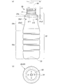
- (A) is a front view of the peeling container of the present embodiment, and (b) is a bottom view of the peeling container of the present embodiment. It is a vertical sectional view of the peeling container of this embodiment. It is a figure which shows typically the structure of the blow molding apparatus of this embodiment. It is a figure which shows the manufacturing process of the preform of this embodiment.
- (A) is a diagram showing the vicinity of the bottom of the first layer in the first injection molding portion, and (b) is a diagram showing the vicinity of the bottom of the preform in the second injection molding portion. It is a perspective view which shows the structural example of the 2nd cavity type of the 1st injection molding part.
- FIG. 1 is a vertical cross-sectional view of the preform 10 of the present embodiment.
- the overall shape of the preform 10 is a bottomed cylindrical shape with one end open and the other end closed.
- the preform 10 includes a body portion 14 formed in a cylindrical shape, a bottom portion 15 that closes the other end side of the body portion 14, and a neck portion 13 formed in an opening on one end side of the body portion 14.
- the preform 10 has a two-layer structure in which a second layer (inner layer) 12 is laminated inside the first layer (outer layer) 11.
- the first layer 11 and the second layer 12 are formed of different thermoplastic resin materials by two-step injection molding as described later.
- the first layer 11 is made of a synthetic resin having excellent moldability and transparency.
- the second layer 12 is made of a synthetic resin having properties (for example, moisture barrier property, gas barrier property, heat resistance, chemical resistance) capable of stably storing the contents of the container and suppressing deterioration (oxidation). Will be done.
- the resin material of the first layer 11 a material having a melting point higher than that of the resin material of the second layer 12 is selected.
- the resin material of the first layer 11 is also referred to as a first resin material
- the resin material of the second layer 12 is also referred to as a second resin material.
- the combination of the first resin material and the second resin material can be appropriately selected according to the specifications of the release container.
- Specific types of materials include, for example, PET (polyethylene terephthalate), PEN (polyethylene naphthalate), PCTA (polycyclohexanedimethylene terephthalate), Tritan (Tritan (registered trademark): copolyester manufactured by Eastman Chemical Co., Ltd.).
- PP polyethylene
- PE polyethylene
- PC polyethylene
- PES polyyester sulfone
- PPSU polyphenyl sulfone
- PS polyyester
- COP / COC cyclic olefin polymer
- PMMA polymethacrylic acid
- Methyl: acrylic acrylic
- PLA polylactic acid
- the first resin material is PET (polyethylene terephthalate), and the second resin material is PP (polypropylene).
- the melting point of PP is about 160 to 170 ° C.
- the melting point of PET is higher than the melting point of PP, which is about 245 to 260 ° C.
- the ratio (t1 / t2) of the thickness t1 of the first layer 11 to the thickness t2 of the second layer 12 is preferably 1.5 or more.
- the thickness ratio is preferably 3.0 or less from the viewpoint of ensuring the transparency of the peeling container to be molded.
- an opening 16 is formed at the center of the bottom portion of the first layer 11 so as to penetrate the first layer 11.
- the opening 16 of the first layer 11 is closed from the inside by the second layer 12.
- the bottom 15 of the preform 10 is formed with a recess 17 for forming an air introduction hole in the peeling container.
- the recess 17 has, for example, a circular cross section and is formed at least at one location with a radial interval from the center of the bottom 15 of the preform 10, but a plurality of recesses 17 are formed along the circumferential direction. You may be.
- the depth of the recess 17 in the thickness direction of the container is set so that at least the recess 17 penetrates the first layer 11 and the surface of the second layer 12 is exposed in the recess 17.
- the recess 17 formed in the preform 10 having a two-layer structure may be referred to as a second recess to distinguish it from the recess (described later) formed only in the first layer 11.
- the cross section of the recess 17 may be a circular shape, an elliptical shape, a polygonal shape, a slit shape, or a shape in which these are combined.
- FIGS. 2 and 3 are a front view and a bottom view of the peeling container 20 of the present embodiment.
- FIG. 3 is a vertical cross-sectional view of the peeling container 20 of the present embodiment.
- the peeling container 20 is a bottle-shaped resin container obtained by stretching and blow molding the preform 10, and contains, for example, a seasoning liquid such as soy sauce.
- the peeling container 20 may be used to store other contents such as a cosmetic liquid for cosmetics.
- the container is sealed by attaching the nozzle head 60, which is an example of the pump member, to the neck portion 21 described later of the peeling container 20 in an airtight state.
- the nozzle head 60 discharges a predetermined amount of the contents of the container from the nozzle in response to the operation of pushing down the top.
- the peeling container 20 has a two-layer structure in which a bag-shaped second layer 12 is laminated inside the first layer 11 as in the preform 10.
- the ratio of the thickness t11 of the first layer 11 to the thickness t12 of the second layer 12 (t11 / t12) is the ratio of the thickness of the preform 10 to the body portion 14 of the preform 10 (t1 /. It is almost the same as t2).
- the peeling container 20 has a neck portion 21 having an opening at the upper end, a cylindrical body portion 22 continuous from the neck portion 21, and a bottom portion 23 continuous from the body portion 22.
- the body portion 22 has a shoulder portion 22a whose one end is connected to the neck portion 21 and expands radially toward the other end, a main body portion 22c whose other end is connected to the bottom portion 23, and the other end and the main body portion of the shoulder portion 22a. It includes a constricted portion 22b that is connected to one end of each of the 22c and connects the shoulder portion 22a and the main body portion 22c.
- the cross section of the peeling container 20 has a substantially circular shape at any position in the axial direction.
- the constricted portion 22b has a first curved surface portion 22b1 whose diameter is reduced from the outer peripheral edge of the shoulder portion 22a toward the lower side (direction in which the bottom portion is located) and an upper side (direction in which the neck portion is located) from one end of the main body portion 22c. It has a second curved surface portion 22b2 whose diameter is reduced toward the surface.
- the diameter of the constricted bottom 22b3, which is connected to the first curved surface portion 22b1 and the second curved surface portion 22b2 and has the smallest diameter in the constricted portion 22b, is the diameter of the other end of the shoulder portion 22a (the outer peripheral edge of the shoulder portion 22a). And smaller than the diameter of the main body 22c.
- the directional dimensions and the like are set so that the nozzle head 60 can be operated by holding the container with one hand.
- the peeling container 20 is configured so that the thumb and the middle finger are supported by being attached to the first curved surface portion 22b1 of the constricted portion 22, and the nozzle head 60 can be pressed with the index finger.
- the radius of curvature (R value) of the first curved surface portion 22b1 is smaller than the radius of curvature of the second curved surface portion 22b2. That is, the constricted portion 22b has a shape in which the first curved surface portion 22b1 close to the shoulder portion 22a is greatly curved, and the second curved surface portion 22b2 close to the main body portion 22c is curved more gently than the first curved surface portion 22b1. ing.
- the finger supporting the constricted portion 22 does not slip and is easily caught by the shoulder portion 22a, so that it becomes easier to support the container.
- the thumb, the middle finger, the ring finger and the like can be easily fitted to the recessed portion 22b, so that the container can be supported and operated with one hand more easily.
- the diameter ( ⁇ 1) of the outer peripheral edge of the shoulder portion 22a is 40 mm or more and 55 mm or less
- the axial length (L1) from the position of the outer peripheral edge of the shoulder portion 22a to the position of the constricted bottom portion of the constricted portion 22b is 12 mm. It is 25 mm or more and 25 mm or less.
- the ratio ( ⁇ 2 / ⁇ 1) of the diameter ( ⁇ 2) of the constricted bottom of the constricted portion 22b to the diameter ( ⁇ 1) of the outer peripheral edge of the shoulder portion 22a is in the range of 0.80 or more and 0.93 or less.
- the diameter ⁇ 2 of the constricted bottom 22b3 of the constricted portion 22b supported by the thumb and the middle finger is the ratio of the diameter ⁇ 1 of the outer peripheral edge of the shoulder portion 22a to the diameter ⁇ 1 of the outer peripheral edge of the shoulder portion 22a to the diameter ⁇ 2 of the constricted bottom 22b3 ( ⁇ 2). It can be specified from / ⁇ 1). If the diameter ⁇ 2 of the bottom of the constriction is large, it becomes difficult to support the container by sandwiching it between the thumb and the middle finger, which reduces the usability of the container.
- the axial length L1 from the position of the outer peripheral edge of the shoulder portion 22a to the position of the constricted bottom portion 22b3 of the constricted portion 22b is 12 mm or more. It is ergonomically preferable to have a range of 25 mm or less.
- the smaller the value the easier it is for the finger attached to the bottom of the constriction to get caught on the shoulder 22a.
- the ratio of ⁇ 2 / ⁇ 1 is reduced and the shoulder portion 22a protrudes greatly from the bottom of the constriction, it becomes difficult to shape the peeling container 20 at the time of blow molding, and the peeling container 20 is used. At this time, the inner layer (second layer 12) may be difficult to peel off from the outer layer (first layer 11) at the overhanging portion of the shoulder portion 22a.
- the axial spacing L2 is preferably 65 mm or less.
- the body 14 and the bottom 15 of the preform 10 are expanded by the stretching blow, so that the body 22 and the bottom 23 of the peeling container 20 are shaped. Further, during the stretching blow, the recess 17 of the preform 10 is stretched, so that the bottom 23 of the peeling container 20 has an air introduction hole penetrating the first layer 11 as shown in FIG. 2 (b). At least one of 24 is formed.
- the air introduction hole 24 preferably has a diameter of 0.5 mm or more and a circular or elliptical shape. Further, it is desirable that a plurality (for example, four or more) of air introduction holes 24 are formed in the bottom portion 23 of the peeling container 20. Further, it is preferable that the plurality of air introduction holes 24 are arranged radially with reference to the center (gate portion) of the bottom portion 23 of the peeling container 20. When forming a plurality of air introduction holes 24, each air introduction hole 24 may be formed so as to be point-symmetrical with respect to the center of the bottom portion 23, or may be arranged so as to be deviated from the point-symmetrical position. good. Note that FIG. 2B shows an example in which the four air introduction holes 24 are arranged point-symmetrically.
- the contents are filled in the space inside the second layer 12.
- the contents when the contents are discharged from the second layer 12 by pressing the nozzle head 60, air gradually flows in between the first layer 11 and the second layer 12 from the air introduction hole 24, and the first The layer 11 and the second layer 12 are peeled off.
- the volume occupied by the contents in the container can be replaced with air without exposing the contents of the second layer 12 to air, and the contents filled in the second layer 12 can be discharged to the outside of the container.
- an opening 25 (non-laminated portion, single layer portion) penetrating the first layer 11 is formed as in the preform 10.
- the opening 25 is filled with the material of the second layer 12 so as to close the opening 25, and the second layer 12 is exposed to the outside of the first layer 11 in the vicinity of the opening 25 of the bottom 23 of the peeling container 20. It has become.
- the second layer 12 is partially fixed to the first layer 11 by exposing the second layer 12 to the outside of the first layer 11 in the opening 25 of the peeling container 20, and the second layer 12 with respect to the first layer 11 Misalignment is suppressed.
- FIG. 4 is a diagram schematically showing the configuration of the blow molding apparatus 30 of the present embodiment.
- the blow molding device 30 of the present embodiment is an example of a manufacturing device for the peeling container 20, and the peeling container 20 is made by utilizing the heat possessed (internal heat amount) at the time of injection molding without cooling the preform 10 to room temperature.
- a hot parison method also called a one-stage method for blow molding is adopted.
- the blow molding apparatus 30 conveys the first injection molding unit 31, the first temperature adjustment unit 32, the second injection molding unit 33, the second temperature adjustment unit 34, the blow molding unit 35, the take-out unit 36, and the like. It includes a mechanism 37.
- the first injection molding unit 31, the first temperature adjustment unit 32, the second injection molding unit 33, the second temperature adjustment unit 34, the blow molding unit 35, and the take-out unit 36 have the same predetermined angle (for example, the same predetermined angle) about the transport mechanism 37. It is arranged at a position rotated by 60 degrees).
- the blow molding apparatus 30 may be configured to omit the first temperature adjusting unit 32 (in this case, each molding station is arranged at a position rotated by 72 degrees around the transfer mechanism 37). Further, the first injection molding unit 31 and the second injection molding unit 33 are provided with a core type elevating mechanism (not shown) above the transport mechanism 37.
- the transfer mechanism 37 includes a rotating plate (transfer plate) 37a that rotates about an axis in the direction perpendicular to the paper surface of FIG. On the rotating plate 37a, one or more neck molds 37b (not shown in FIG. 4) holding the neck portion 13 of the preform 10 (or the neck portion 21 of the peeling container 20) are arranged at predetermined angles.
- the transport mechanism 37 rotates the rotary plate 37a to adjust the preform 10 (or the peeling container 20) held by the neck mold 37b to the first injection molding unit 31, the second injection molding unit 33, and the second temperature adjustment.
- the section 34, the blow molding section 35, and the take-out section 36 are conveyed in this order.
- the transport mechanism 37 can also raise and lower the rotary plate 37a, and also performs operations related to mold closing and mold opening (release) in the first injection molding unit 31 and the second injection molding unit 33.
- the first injection molding unit 31 includes a cavity mold 40, a core mold 41, and a hot runner mold 42, and cooperates with a neck mold 37b that is conveyed during molding to manufacture the first layer 11 of the preform 10.
- the cavity type 40 is composed of a first cavity type 40A on the opening side (upper side) and a second cavity type 40B on the bottom surface side (lower side).
- a first injection device 38 that supplies a first resin material to the hot runner mold 42 is connected to the first injection molding unit 31.
- the cavity type 40 and the hot runner type 42 are fixed to the machine base of the blow molding apparatus 30 in an integrated state.
- the core type 41 is fixed to the core type elevating mechanism.
- FIG. 5 (a) and 5 (b) show a first injection molding unit 31 for molding the first layer 11 of the preform 10 of the present embodiment.
- FIG. 6A is a diagram showing the vicinity of the bottom of the first layer 11 in the first injection molding unit 31.
- FIG. 7 is a perspective view showing a configuration example of the cavity type 40 (second cavity type 40B) of the first injection molding unit 31.
- the cavity type 40 defines (defines) the shape of the outer circumference of the first layer 11.
- the first cavity mold 40A is a mold facing the opening side of the cavity mold 40 (the side that comes into contact with the neck mold 37b when the mold is closed), and defines the shape of the outer periphery of the body of the first layer 11.
- the second cavity mold 40B is a mold facing the bottom surface side (the side that comes into contact with the hot runner mold 42) of the cavity mold 40, and defines the shape of the outer periphery of the bottom portion of the first layer 11.
- the second cavity type 40B further includes a gate portion 40Ba that guides the resin material from the hot runner type 42 to the cavity surface.
- the hot runner type 42 has a resin supply unit 42a that introduces the first resin material plasticized (melted) by the first injection device 38 into the second cavity type 40B.
- the core mold 41 is a mold that defines the shape of the inner peripheral side of the first layer 11, and is inserted into the inner peripheral side of the cavity mold 40 from above.
- the neck mold 37b conveyed at the time of molding defines the outer shape of the neck portion 13 of the preform 10 (first layer 11).
- the cavity mold 40 and the core mold 41 and the neck mold 37b of the transport mechanism 37 are molded and closed to form the first layer.
- Form 11 mold spaces are formed. Then, by pouring the first resin material from the bottom of the mold space through the hot runner mold 42, the first layer 11 of the preform 10 is manufactured in the first injection molding portion 31.
- a columnar (or tapered columnar or prismatic) first protrusion 44 is provided at a predetermined position. ing. As shown in FIG. 7A, at least one of the first protrusions 44 is arranged at intervals in the radial direction from the center of the bottom where the resin supply portion 42a is located. As shown in FIG. 6A, the protrusion amount h1 of the first protrusion 44 with respect to the cavity reference surface of the second cavity type 40B (the cavity surface that defines the shape of the lower end side of the bottom outer peripheral surface of the first layer 11). Is about the same size as the thickness of the first layer 11.
- the tip of the first protrusion 44 faces the surface of the core mold 41 (arranged in the vicinity of the surface of the core mold 41).
- the first protrusion 44 forms a circular recess 11a in the first layer 11 at a position corresponding to the recess 17 of the preform 10.
- the recess 11a of the first layer 11 may penetrate the first layer 11 or may have a thin film formed between the core mold 41 and the first protrusion 44.
- the recess 11a of the first layer 11 formed by the first injection molding portion 31 is also referred to as a first recess.
- the resin supply portion 42a of the hot runner type 42 has a rod-shaped member that opens and closes a valve pin 43 (resin supply portion 42a) that can move in the axial direction to a position close to the core mold 41. ) Is provided.
- the valve pin 43 is housed inside the hot runner mold 42 until the first resin material is filled in the mold space, and after the first resin material is filled in the mold space, the end of the gate portion 40Ba on the cavity side is open. It protrudes to a position closer to the core mold 41.
- a thin film portion 18 having a thickness thinner than the peripheral portion of the resin material can be formed in the center of the bottom portion of the first layer 11.
- the neck mold 37b of the transport mechanism 37 is not opened and the first layer 11 of the preform 10 is held and conveyed as it is.
- the number of preforms 10 simultaneously molded by the first injection molding unit 31 that is, the number of peeling containers 20 that can be simultaneously molded by the blow molding apparatus 30) can be appropriately set.
- the first temperature adjusting unit 32 adjusts the temperature of a temperature adjusting mold (a heating pot or a temperature adjusting pot (temperature adjusting pot) for adjusting the temperature of the first layer 11 from the outside) and the first layer 11 from the inside (not shown). It is equipped with a heating rod, a temperature control rod (temperature control rod), or an air introduction rod).
- the first temperature adjusting unit 32 cools (or heats) the first layer 11 which is in a high temperature state after injection molding by accommodating it in a temperature adjusting mold kept at a predetermined temperature.
- the first temperature adjusting unit 32 also has a function of adjusting the temperature distribution of the first layer 11 to a predetermined state before being conveyed to the second injection molding unit 33.
- the second injection molding unit 33 includes a cavity mold 50, a core mold 51, and a hot runner mold 52, and cooperates with a neck mold 37b conveyed at the time of molding to provide a second layer 12 on the inner peripheral side of the first layer 11. Injection molding.
- the cavity type 50 is composed of a first cavity type 50A on the opening side (upper side) and a second cavity type 50B on the bottom surface side (lower side).
- a second injection device 39 that supplies a second resin material to the hot runner mold 52 is connected to the second injection molding unit 33.
- FIG. 5C shows a second injection molding unit 33 that molds the second layer 12 of the preform 10.
- FIG. 6B is a diagram showing the vicinity of the bottom of the preform 10 in the second injection molding unit 33.
- the cavity mold 50 is a mold for accommodating the first layer 11.
- the first cavity mold 50A is a mold facing the opening side of the cavity mold 50 and accommodates the body portion of the first layer 11.
- the second cavity mold 50B is a mold facing the bottom surface side of the cavity mold 50, and accommodates the bottom portion of the first layer 11.
- the second cavity type 50B further includes a gate portion 50Ba that guides the resin material from the hot runner type 52 to the cavity surface.
- the hot runner type 52 has a resin supply unit 52a for introducing a second resin material plasticized (melted) by the second injection device 39.
- the core mold 51 is a mold that defines the shape of the inner peripheral side of the second layer 12, and is inserted into the inner peripheral side of the cavity mold 50 from above.
- the hot runner type 52 may have a structure having a valve pin like the hot runner type 42. However, the position of the valve pin when closing the second resin material is set to a position that does not protrude from the opening end on the cavity side of the gate portion 50Ba.
- the second injection molding unit 33 accommodates the first layer 11 of the preform 10 injection-molded by the first injection molding unit 31.
- the second injection molding portion 33 When the second injection molding portion 33 is closed, a mold space is formed between the inner peripheral side of the first layer 11 and the surface of the core mold 51.
- the second layer 12 was laminated on the inner peripheral side of the first layer 11 by pouring the second resin material from the bottom of the mold space through the hot runner mold 52.
- the preform 10 is formed.
- a preform is formed at a predetermined position corresponding to the first protrusion 44 of the first injection molding portion 31.
- a second protrusion 54 such as a columnar shape corresponding to the shape of the recess 17 of 10 is provided. The second protrusion 54 is inserted into the recess 11a of the first layer 11 when the first layer 11 is housed in the second injection molding portion 33.
- the basic configuration of the protrusions and the like in the second cavity mold 50B is substantially the same as that of the second cavity mold 40B of the first injection molding portion 31.
- the second protrusion 54 from the cavity reference surface of the second cavity type 50B (the cavity surface that abuts on the lower end side region of the bottom outer peripheral surface of the first layer 11).
- the protrusion amount h2 of is larger than the thickness of the first layer 11. That is, the protrusion amount h2 of the second protrusion 54 is larger than the protrusion amount h1 of the first protrusion 44 (h2> h1). Therefore, when the second injection molding portion 33 is closed, the tip of the second protrusion 54 penetrates the recess 11a of the first layer 11 and projects to the inner peripheral side of the first layer 11.
- the protrusion amount h2 of the second protrusion 54 is set to be smaller than the thickness of the preform 10. That is, in the injection molding by the second injection molding portion 33, the second resin material flows between the core mold 51 and the second protrusion 54, so that the second protrusion 54 penetrates the second layer 12. No holes are formed.
- the second temperature adjusting unit 34 adjusts the temperature of a mold unit (heating pot or temperature adjusting pot (temperature adjusting pot) for adjusting the temperature of the preform 20 from the outside) and the preform 20 from the inside (not shown). It is equipped with a heating rod, a temperature control rod (temperature control rod), or an air introduction rod).
- the second temperature adjusting unit 34 accommodates the preform 10 conveyed from the second injection molding unit 33 in a mold unit kept at a predetermined temperature to equalize the temperature and remove the unbalanced temperature of the preform 10. The temperature is adjusted to a temperature suitable for the final blow (for example, about 90 ° C to 105 ° C).
- the second temperature adjusting unit 34 also has a function of cooling the preform 10 in a high temperature state after injection molding.
- the blow molding unit 35 blow-molds the preform 10 whose temperature has been adjusted by the temperature adjusting unit 33 to manufacture the peeling container 20.
- the blow molding unit 35 includes a blow cavity type, which is a pair of split molds corresponding to the shape of the release container 20, a bottom type, a drawing rod, and an air introduction member (all not shown).
- the blow molding unit 35 blow molds while stretching the preform 10. As a result, the preform 10 is shaped into a blow cavity type shape, and the peeling container 20 can be manufactured.
- the take-out unit 36 is configured to open the neck portion 21 of the release container 20 manufactured by the blow molding unit 35 from the neck mold 37b and take out the release container 20 to the outside of the blow molding apparatus 30.
- FIG. 8 is a flowchart showing the process of the manufacturing method of the peeling container 20.
- Step S101 First injection molding step
- the first resin material from the first injection device 38 is placed in the mold space formed by the cavity mold 40, the core mold 41, and the neck mold 37b. Is injected, and the first layer 11 of the preform 10 is molded. At this time, the first protrusion 44 forms a recess 11a at the bottom of the first layer 11.
- the first injection molding section 31 is opened and the first layer is released.
- the rotating plate 37a of the transport mechanism 37 rotates by a predetermined angle, and the first layer 11 of the preform 10 held by the neck mold 37b retains heat during injection molding. It is conveyed to the first temperature adjusting unit 32 in a state of being contained.
- Step S102 First temperature adjustment step
- the first layer 11 of the preform 10 is housed in the temperature adjusting mold, and the cooling of the first layer 11 and the adjustment of the temperature distribution (leveling and removing uneven temperature) are performed. Will be done.
- the first temperature adjustment step may be omitted.
- the rotating plate 37a of the transport mechanism 37 rotates by a predetermined angle, and the temperature-adjusted first layer 11 held by the neck mold 37b is the second injection molding portion. It is transported to 33.
- Step S103 Second injection molding step
- the first layer 11 of the preform 10 is housed in the second injection molding unit 33, and the injection molding of the second layer 12 is performed.
- a mold space is provided between the inner peripheral side of the first layer 11 and the surface of the core mold 51 facing the inner circumference of the first layer 11.
- the formed mold space is filled with a second resin material from the hot runner mold 52.
- the thin film portion 18 is formed at the bottom of the first layer 11, the thin film portion 18 is broken by the injection pressure of the second resin material to form an opening 16 at the bottom, and the opening 16 is formed from the above opening 16.
- the second resin material is guided to the inner peripheral side of the first layer 11.
- the temperature of the second resin material filled in the second injection molding unit 33 is set to a temperature lower than the melting point of the first resin material. Further, the surface temperature of the first layer 11 when the second resin material is filled in the second injection molding unit 33 is cooled to a temperature equal to or lower than the melting point of the second resin material.
- the cavity mold 50 faces the outer peripheral side of the first layer 11, and the shape of the first layer 11 is held from the outer peripheral side by the cavity mold 50. Therefore, even if the second resin material comes into contact with the first layer 11, the thermal deformation of the first layer 11 can be suppressed.
- the recess 17 of the preform 10 is closed with the second resin material. There is no. Further, since the tip of the second protrusion 54 in the second injection molding portion 33 projects to the inner peripheral side of the first layer, the recess 17 of the preform 10 formed by the second protrusion 54 is the first. The shape is such that the surface of the second layer 12 is exposed in the recess 17 through the layer 11.
- the preform 10 in which the second layer 12 is laminated on the inner peripheral side of the first layer 11 is manufactured by the first injection molding step and the second injection molding step.
- the rotating plate 37a of the transport mechanism 37 rotates by a predetermined angle, and the preform 10 held in the neck mold 37b contains the heat retained during injection molding. Is conveyed to the second temperature adjusting unit 34.
- Step S104 Second temperature adjustment step
- the preform 10 is housed in the temperature adjusting mold unit, and the temperature is adjusted so that the temperature of the preform 10 approaches the temperature suitable for the final blow.
- the rotating plate 37a of the transport mechanism 37 rotates by a predetermined angle, and the temperature-adjusted preform 10 held in the neck mold 37b is transported to the blow molding unit 35.
- Step S105 Blow molding step
- the blow molding unit 35 performs blow molding of the release container 20.
- the blow cavity mold is closed, the preform 10 is housed in the mold space, and the air introduction member (blow core) is lowered, so that the air introduction member is brought into contact with the neck portion 13 of the preform 10.
- the drawing rod is lowered to suppress the bottom portion 15 of the preform 10 from the inner surface, and the preform 10 is stretched on the horizontal axis by supplying blow air from the air introduction member while stretching the vertical axis as necessary. ..
- the preform 10 is bulged and shaped so as to be in close contact with the blow cavity type mold space, and is blow molded into the release container 20.
- Step S106 Container removal step
- the blow cavity mold is opened.
- the release container 20 can be moved from the blow molding unit 35.
- the rotating plate 37a of the transport mechanism 37 rotates by a predetermined angle, and the release container 20 is transported to the take-out unit 36.
- the neck portion 21 of the peeling container 20 is released from the neck mold 37b, and the peeling container 20 is taken out to the outside of the blow molding apparatus 30.
- the waiting times of the first injection molding step, the first temperature adjusting step, the second injection molding step, the second temperature adjusting step, the blow molding step, and the container taking-out step are all the same length. Become. Similarly, the transport time between each step is the same length.
- the first layer 11 (outer layer) of the preform 10 is molded in the first injection molding step, and the second layer 11 is formed inside the first layer 11 from the opening 16 of the first layer 11 in the second injection molding step.
- the layer 12 (inner layer) is injection-molded to produce a preform 10 having a two-layer structure.
- the outer layer can be formed first with a resin material having a high melting point, and then the inner layer can be formed with a resin material having a lower melting point than the outer layer.
- the preform 10 having a two-layer structure suitable for the specifications of the peeling container 20 can be manufactured by continuously performing injection molding of the inner layer while the outer layer has the heat retained at the time of injection molding.
- the preform 10 having a two-layer structure is released in a state where both the outer layer and the inner layer have the heat retained during injection molding. Therefore, when the peeling container 20 is manufactured by the hot parison type blow molding method. A suitable preform 10 can be obtained.
- the preform 10 having the above-mentioned two-layer structure is stretch-blow molded to produce the peeling container 20 in a state of having the heat retained at the time of injection molding. Therefore, in the present embodiment, the peeling container 20 having excellent aesthetic appearance, physical strength, and the like can be manufactured by the hot parison type blow molding method. Compared with the cold parison type blow molding, in the present embodiment, the manufactured preform 10 does not need to be cooled to near room temperature, and the step of reheating the preform 10 is also unnecessary. Therefore, according to the present embodiment, a series of steps from injection molding of the preform 10 to blow molding of the peeling container 20 can be completed in a relatively short time, and the peeling container 20 can be manufactured in a shorter cycle.
- the recess 11a is formed in the first layer 11 by the first protrusion 44 in the first injection molding step. Then, in the second injection molding step, the recess 11a of the first layer 11 is made to penetrate the second protrusion 54 having a larger protrusion amount than the first protrusion 44, and the recess 17 is formed in the bottom 15 of the preform 10. do. As a result, in the peeling container 20, the air introduction hole 24 that penetrates the first layer 11 and reaches the surface of the second layer 12 can be reliably formed.
- FIG. 7B shows an example in which the first protrusions 44 are provided at two places in the second cavity type 40B of the first injection molding part 31.
- the two first protrusions 44 are arranged at positions symmetrical with respect to the central axis with an interval of 180 °.
- the number of the first protrusions 44 may be three or more. At that time, it is preferable that each of the first protrusions 44 is arranged in a point-symmetrical positional relationship with respect to the central axis.
Abstract
This peeling container has an outer layer formed of a first resin material and a bag-shaped inner layer that is provided on the inner peripheral side of the outer layer and formed of a second resin material different from the first resin material, and a hole for introducing air between the outer layer and the inner layer is provided on the outer layer. The peeling container is provided with a neck part having an opening communicating with the inside of the inner layer, a shoulder part continuously expanding in a radial direction from the neck part, a bottomed cylindrical body part, and a constricted part connecting the shoulder part and the body part to each other. The diameter of the outer peripheral edge of the shoulder part is 40-55 mm inclusive. An axial length from the outer peripheral edge of the shoulder part to a constricted bottom part at which the diameter of the constricted part becomes smallest is 12-25 mm inclusive. The ratio of the diameter of the constricted bottom part to the diameter of the outer peripheral edge of the shoulder part is 0.8-0.93 inclusive.
Description
本発明は、剥離容器および剥離容器の製造方法に関する。
The present invention relates to a peeling container and a method for manufacturing a peeling container.
従来から、内層および外層の二層構造を有し、内容物の排出に応じて内層が外層から剥離してゆく樹脂製の剥離容器が知られている。この種の剥離容器は、デラミボトルまたはエアレスボトルとも称され、例えば醤油などの調味液や化粧品の化粧液の容器に利用されている。
現状、この種の剥離容器の製造では、押出ブロー方式の利用が一般的であって、延伸ブロー方式の利用は少ない(特許文献1参照)。 Conventionally, a resin peeling container having a two-layer structure of an inner layer and an outer layer, in which the inner layer is peeled from the outer layer according to the discharge of the contents, has been known. This type of peeling container is also called a derami bottle or an airless bottle, and is used as a container for a seasoning liquid such as soy sauce or a cosmetic liquid for cosmetics.
At present, in the production of this type of peeling container, the extrusion blow method is generally used, and the stretch blow method is rarely used (see Patent Document 1).
例えば、剥離容器の外観、寸法精度、物性強度などの向上や、無駄な材料の抑制による環境負荷の低減の観点から、剥離容器の製造において、射出成形工程からブロー成形工程までを連続して行う1ステージのホットパリソン式のブロー成形法を適用することが検討されている。
For example, from the viewpoint of improving the appearance, dimensional accuracy, physical strength, etc. of the peeling container and reducing the environmental load by suppressing wasteful materials, the injection molding process to the blow molding process are continuously performed in the manufacturing of the peeling container. It is being considered to apply a one-stage hot parison blow molding method.
しかしながら、剥離容器は、外層用の樹脂材料の融点が内層用の樹脂材料の融点より高く設定されることが多い。二層構造のプリフォームを成形する射出成形工程において、内層を形成した後に高温の外層の樹脂材料を充填すると、外層の樹脂材料に接触した内層の表面が溶融して熱変形してしまう。このため、ホットパリソン式のブロー成形法を適用して剥離容器を製造すること自体が極めて困難である。
However, in the peeling container, the melting point of the resin material for the outer layer is often set higher than the melting point of the resin material for the inner layer. In the injection molding step of molding a preform having a two-layer structure, if the resin material of the outer layer having a high temperature is filled after the inner layer is formed, the surface of the inner layer in contact with the resin material of the outer layer is melted and thermally deformed. Therefore, it is extremely difficult to manufacture a peeling container by applying a hot parison type blow molding method.
また、例えば、首部にポンプ部材を取り付けた剥離容器を片手持ちで使用する場合、容器のグリップ性を考慮した形状とすることが好ましい。一方で、剥離容器の形状は、容器の成形や内層の剥離のしやすさも考慮する必要がある。
Further, for example, when a peeling container having a pump member attached to the neck is used with one hand, it is preferable to have a shape in consideration of the grip of the container. On the other hand, for the shape of the peeling container, it is necessary to consider the ease of forming the container and peeling the inner layer.
そこで、本発明はこのような課題に鑑みてなされたものであり、容器の成形や内層の剥離のしやすさを考慮しつつ、片手持ちでの容器のグリップ性を向上させた剥離容器を提供することを目的とする。
Therefore, the present invention has been made in view of such a problem, and provides a peeling container having improved grip of the container with one hand while considering the ease of forming the container and peeling the inner layer. The purpose is to do.
本発明の一態様である剥離容器は、第1の樹脂材料で形成された外層と、外層の内周側に設けられ、第1の樹脂材料とは異なる第2の樹脂材料で形成された袋状の内層とを有し、外層と内層の間に空気を導入するための孔が外層に設けられている。剥離容器は、内層の内側に連通する開口を有する首部と、首部から連続して径方向に拡がる肩部と、有底筒状の本体部と、肩部と本体部をつなぐくびれ部と、を備える。肩部の外周縁の直径は40mm以上55mm以下であり、肩部の外周縁からくびれ部で最も縮径するくびれ底部までの軸方向長さは、12mm以上25mm以下であり、肩部の外周縁の直径に対するくびれ底部の直径の比は、0.80以上0.93以下である。
The peeling container according to one aspect of the present invention is a bag formed of an outer layer made of a first resin material and a second resin material provided on the inner peripheral side of the outer layer and different from the first resin material. It has a shaped inner layer, and a hole for introducing air is provided in the outer layer between the outer layer and the inner layer. The peeling container includes a neck portion having an opening communicating with the inside of the inner layer, a shoulder portion continuously extending in the radial direction from the neck portion, a bottomed cylindrical main body portion, and a constricted portion connecting the shoulder portion and the main body portion. Be prepared. The diameter of the outer peripheral edge of the shoulder is 40 mm or more and 55 mm or less, and the axial length from the outer peripheral edge of the shoulder to the bottom of the constriction that is most reduced in diameter is 12 mm or more and 25 mm or less, and the outer peripheral edge of the shoulder. The ratio of the diameter of the bottom of the constriction to the diameter of the neck is 0.80 or more and 0.93 or less.
本発明の一態様によれば、容器の成形や内層の剥離のしやすさを考慮しつつ、片手持ちでの容器のグリップ性を向上させることができる。
According to one aspect of the present invention, it is possible to improve the grip of the container with one hand while considering the ease of molding the container and peeling off the inner layer.
以下、本発明の実施形態について図面を参照して説明する。
実施形態では説明を分かり易くするため、本発明の主要部以外の構造や要素については、簡略化または省略して説明する。また、図面において、同じ要素には同じ符号を付す。なお、図面に示す各要素の形状、寸法などは模式的に示したもので、実際の形状、寸法などを示すものではない。 Hereinafter, embodiments of the present invention will be described with reference to the drawings.
In the embodiment, in order to make the description easy to understand, the structures and elements other than the main part of the present invention will be described in a simplified or omitted manner. Further, in the drawings, the same elements are designated by the same reference numerals. It should be noted that the shapes, dimensions, etc. of each element shown in the drawings are schematically shown, and do not indicate the actual shapes, dimensions, etc.
<プリフォームの構成例>
まず、図1を参照して、本実施形態に係る剥離容器用のプリフォームの構成例を説明する。図1は本実施形態のプリフォーム10の縦断面図である。プリフォーム10の全体形状は、一端側が開口され、他端側が閉塞された有底円筒形状である。プリフォーム10は、円筒状に形成された胴部14と、胴部14の他端側を閉塞する底部15と、胴部14の一端側の開口に形成された首部13とを備えている。 <Preform configuration example>
First, a configuration example of the preform for the peeling container according to the present embodiment will be described with reference to FIG. FIG. 1 is a vertical cross-sectional view of thepreform 10 of the present embodiment. The overall shape of the preform 10 is a bottomed cylindrical shape with one end open and the other end closed. The preform 10 includes a body portion 14 formed in a cylindrical shape, a bottom portion 15 that closes the other end side of the body portion 14, and a neck portion 13 formed in an opening on one end side of the body portion 14.
まず、図1を参照して、本実施形態に係る剥離容器用のプリフォームの構成例を説明する。図1は本実施形態のプリフォーム10の縦断面図である。プリフォーム10の全体形状は、一端側が開口され、他端側が閉塞された有底円筒形状である。プリフォーム10は、円筒状に形成された胴部14と、胴部14の他端側を閉塞する底部15と、胴部14の一端側の開口に形成された首部13とを備えている。 <Preform configuration example>
First, a configuration example of the preform for the peeling container according to the present embodiment will be described with reference to FIG. FIG. 1 is a vertical cross-sectional view of the
プリフォーム10は、第1層(外層)11の内側に第2層(内層)12が積層された二層構造を有している。この第1層11と第2層12は、後述のように2段階の射出成形によりそれぞれ異なる熱可塑性の樹脂材料で形成される。第1層11は、成形性や透明性に優れた性質を有する合成樹脂で構成される。一方、第2層12は、容器の内容物を安定的に保管して劣化(酸化)を抑制できる性質(例えば、水分バリア性、ガスバリア性、耐熱性、耐薬品性)を有する合成樹脂で構成される。また、第1層11の樹脂材料には、第2層12の樹脂材料よりも融点が高いものが選択される。
The preform 10 has a two-layer structure in which a second layer (inner layer) 12 is laminated inside the first layer (outer layer) 11. The first layer 11 and the second layer 12 are formed of different thermoplastic resin materials by two-step injection molding as described later. The first layer 11 is made of a synthetic resin having excellent moldability and transparency. On the other hand, the second layer 12 is made of a synthetic resin having properties (for example, moisture barrier property, gas barrier property, heat resistance, chemical resistance) capable of stably storing the contents of the container and suppressing deterioration (oxidation). Will be done. Further, as the resin material of the first layer 11, a material having a melting point higher than that of the resin material of the second layer 12 is selected.
以下、第1層11の樹脂材料を第1の樹脂材料とも称し、第2層12の樹脂材料を第2の樹脂材料とも称する。
第1の樹脂材料と第2の樹脂材料の組み合わせは、剥離容器の仕様に応じて適宜選択できる。具体的な材料の種類としては、例えば、PET(ポリエチレンテレフタレート)、PEN(ポリエチレンナフタレート)、PCTA(ポリシクロヘキサンジメチレンテレフタレート)、Tritan(トライタン(登録商標):イーストマンケミカル社製のコポリエステル)、PP(ポリプロピレン)、PE(ポリエチレン)、PC(ポリカーボネート)、PES(ポリエーテルスルホン)、PPSU(ポリフェニルスルホン)、PS(ポリスチレン)、COP/COC(環状オレフィン系ポリマー)、PMMA(ポリメタクリル酸メチル:アクリル)、PLA(ポリ乳酸)などが挙げられる。 Hereinafter, the resin material of thefirst layer 11 is also referred to as a first resin material, and the resin material of the second layer 12 is also referred to as a second resin material.
The combination of the first resin material and the second resin material can be appropriately selected according to the specifications of the release container. Specific types of materials include, for example, PET (polyethylene terephthalate), PEN (polyethylene naphthalate), PCTA (polycyclohexanedimethylene terephthalate), Tritan (Tritan (registered trademark): copolyester manufactured by Eastman Chemical Co., Ltd.). , PP (polyethylene), PE (polyethylene), PC (polyester), PES (polyester sulfone), PPSU (polyphenyl sulfone), PS (polyester), COP / COC (cyclic olefin polymer), PMMA (polymethacrylic acid) Methyl: acrylic), PLA (polylactic acid) and the like.
第1の樹脂材料と第2の樹脂材料の組み合わせは、剥離容器の仕様に応じて適宜選択できる。具体的な材料の種類としては、例えば、PET(ポリエチレンテレフタレート)、PEN(ポリエチレンナフタレート)、PCTA(ポリシクロヘキサンジメチレンテレフタレート)、Tritan(トライタン(登録商標):イーストマンケミカル社製のコポリエステル)、PP(ポリプロピレン)、PE(ポリエチレン)、PC(ポリカーボネート)、PES(ポリエーテルスルホン)、PPSU(ポリフェニルスルホン)、PS(ポリスチレン)、COP/COC(環状オレフィン系ポリマー)、PMMA(ポリメタクリル酸メチル:アクリル)、PLA(ポリ乳酸)などが挙げられる。 Hereinafter, the resin material of the
The combination of the first resin material and the second resin material can be appropriately selected according to the specifications of the release container. Specific types of materials include, for example, PET (polyethylene terephthalate), PEN (polyethylene naphthalate), PCTA (polycyclohexanedimethylene terephthalate), Tritan (Tritan (registered trademark): copolyester manufactured by Eastman Chemical Co., Ltd.). , PP (polyethylene), PE (polyethylene), PC (polyester), PES (polyester sulfone), PPSU (polyphenyl sulfone), PS (polyester), COP / COC (cyclic olefin polymer), PMMA (polymethacrylic acid) Methyl: acrylic), PLA (polylactic acid) and the like.
一例として、第1の樹脂材料は、PET(ポリエチレンテレフタレート)であり、第2の樹脂材料は、PP(ポリプロピレン)である。PPの融点は160~170℃程度であり、PETの融点はPPの融点よりも高く、245~260℃程度である。
As an example, the first resin material is PET (polyethylene terephthalate), and the second resin material is PP (polypropylene). The melting point of PP is about 160 to 170 ° C., and the melting point of PET is higher than the melting point of PP, which is about 245 to 260 ° C.
また、プリフォーム10の胴部14において、第2層12の厚さt2に対する第1層11の厚さt1の比(t1/t2)は1.5以上であることが好ましい。当該厚さの比は、成形される剥離容器の透明性を確保する観点から3.0以下であることが好ましい。
Further, in the body portion 14 of the preform 10, the ratio (t1 / t2) of the thickness t1 of the first layer 11 to the thickness t2 of the second layer 12 is preferably 1.5 or more. The thickness ratio is preferably 3.0 or less from the viewpoint of ensuring the transparency of the peeling container to be molded.
また、プリフォーム10の底部15において、第1層11の底部の中心には第1層11を貫通して開口部16が形成されている。第1層11の開口部16は、第2層12によって内側から塞がれている。
Further, in the bottom portion 15 of the preform 10, an opening 16 is formed at the center of the bottom portion of the first layer 11 so as to penetrate the first layer 11. The opening 16 of the first layer 11 is closed from the inside by the second layer 12.
また、プリフォーム10の底部15には、剥離容器に空気導入孔を形成するための凹部17が形成されている。凹部17は、例えば横断面が円形状であって、プリフォーム10の底部15の中心から径方向に間隔を空けて少なくとも1か所形成されるが、周方向に沿って凹部17が複数形成されていてもよい。容器の厚さ方向における凹部17の深さは、少なくとも凹部17が第1層11を貫通して、第2層12の表面が凹部17内に露出する寸法に設定されている。なお、二層構造のプリフォーム10に形成される凹部17は、第1層11のみに形成される凹部(後述)と区別し、第2の凹部と称してもよい。また、凹部17の横断面は円形の外、楕円形や多角形、スリット状、またはこれらが組み合わされた形状であってもよい。
Further, the bottom 15 of the preform 10 is formed with a recess 17 for forming an air introduction hole in the peeling container. The recess 17 has, for example, a circular cross section and is formed at least at one location with a radial interval from the center of the bottom 15 of the preform 10, but a plurality of recesses 17 are formed along the circumferential direction. You may be. The depth of the recess 17 in the thickness direction of the container is set so that at least the recess 17 penetrates the first layer 11 and the surface of the second layer 12 is exposed in the recess 17. The recess 17 formed in the preform 10 having a two-layer structure may be referred to as a second recess to distinguish it from the recess (described later) formed only in the first layer 11. Further, the cross section of the recess 17 may be a circular shape, an elliptical shape, a polygonal shape, a slit shape, or a shape in which these are combined.
<剥離容器の構成例>
次に、図2、図3を参照して、本実施形態に係る樹脂製の剥離容器20の構成例を説明する。図2(a)、(b)は、本実施形態の剥離容器20の正面図および底面図である。図3は、本実施形態の剥離容器20の縦断面図である。 <Structure example of peeling container>
Next, a configuration example of theresin peeling container 20 according to the present embodiment will be described with reference to FIGS. 2 and 3. 2 (a) and 2 (b) are a front view and a bottom view of the peeling container 20 of the present embodiment. FIG. 3 is a vertical cross-sectional view of the peeling container 20 of the present embodiment.
次に、図2、図3を参照して、本実施形態に係る樹脂製の剥離容器20の構成例を説明する。図2(a)、(b)は、本実施形態の剥離容器20の正面図および底面図である。図3は、本実施形態の剥離容器20の縦断面図である。 <Structure example of peeling container>
Next, a configuration example of the
剥離容器20は、プリフォーム10を延伸ブロー成形することで得られるボトル形状の樹脂製容器であり、例えば醤油などの調味液が収容される。なお、剥離容器20の用途は、化粧品の化粧液など、他の内容物を収容するものでもよい。
The peeling container 20 is a bottle-shaped resin container obtained by stretching and blow molding the preform 10, and contains, for example, a seasoning liquid such as soy sauce. The peeling container 20 may be used to store other contents such as a cosmetic liquid for cosmetics.
図2(a)において破線で示すように、剥離容器20の後述の首部21には、ポンプ部材の一例であるノズルヘッド60が気密状態で取り付けられることで容器が封止される。ノズルヘッド60は、頂部を押し下げる操作に応じてノズルから容器の内容物を所定量吐出させる。
As shown by the broken line in FIG. 2A, the container is sealed by attaching the nozzle head 60, which is an example of the pump member, to the neck portion 21 described later of the peeling container 20 in an airtight state. The nozzle head 60 discharges a predetermined amount of the contents of the container from the nozzle in response to the operation of pushing down the top.
図3に示すように、剥離容器20は、プリフォーム10と同様に、第1層11の内側に袋状の第2層12が積層された二層構造を有している。剥離容器20の胴部22において、第2層12の厚さt12に対する第1層11の厚さt11の比(t11/t12)は、プリフォーム10の胴部14における厚さの比(t1/t2)とほぼ同様である。
As shown in FIG. 3, the peeling container 20 has a two-layer structure in which a bag-shaped second layer 12 is laminated inside the first layer 11 as in the preform 10. In the body portion 22 of the peeling container 20, the ratio of the thickness t11 of the first layer 11 to the thickness t12 of the second layer 12 (t11 / t12) is the ratio of the thickness of the preform 10 to the body portion 14 of the preform 10 (t1 /. It is almost the same as t2).
図2(a)に示すように、剥離容器20は、上端に開口を有する首部21と、首部21から連続する円筒状の胴部22と、胴部22から連続する底部23とを有している。胴部22は、一端が首部21に接続されて他端に向けて径方向に拡がる肩部22aと、他端が底部23に接続される本体部22cと、肩部22aの他端および本体部22cの一端にそれぞれ接続され、肩部22aと本体部22cを繋ぐくびれ部22bを含む。なお、剥離容器20の横断面は軸方向のいずれの位置でも略円形状である。
As shown in FIG. 2A, the peeling container 20 has a neck portion 21 having an opening at the upper end, a cylindrical body portion 22 continuous from the neck portion 21, and a bottom portion 23 continuous from the body portion 22. There is. The body portion 22 has a shoulder portion 22a whose one end is connected to the neck portion 21 and expands radially toward the other end, a main body portion 22c whose other end is connected to the bottom portion 23, and the other end and the main body portion of the shoulder portion 22a. It includes a constricted portion 22b that is connected to one end of each of the 22c and connects the shoulder portion 22a and the main body portion 22c. The cross section of the peeling container 20 has a substantially circular shape at any position in the axial direction.
くびれ部22bは、肩部22aの外周縁から下側(底部が位置する方向)に向けて縮径する第1の曲面部22b1と、本体部22cの一端から上側(首部が位置する方向)に向けて縮径する第2の曲面部22b2を有する。第1の曲面部22b1と第2の曲面部22b2に接続され、くびれ部22bで最も縮径しているくびれ底部22b3の径は、肩部22aの他端(肩部22aの外周縁)の径および本体部22cの径よりも小さい。
The constricted portion 22b has a first curved surface portion 22b1 whose diameter is reduced from the outer peripheral edge of the shoulder portion 22a toward the lower side (direction in which the bottom portion is located) and an upper side (direction in which the neck portion is located) from one end of the main body portion 22c. It has a second curved surface portion 22b2 whose diameter is reduced toward the surface. The diameter of the constricted bottom 22b3, which is connected to the first curved surface portion 22b1 and the second curved surface portion 22b2 and has the smallest diameter in the constricted portion 22b, is the diameter of the other end of the shoulder portion 22a (the outer peripheral edge of the shoulder portion 22a). And smaller than the diameter of the main body 22c.
肩部22aの外周縁の直径、くびれ部22bにおけるくびれ底部22b3の直径、肩部22aの外周縁からくびれ底部22b3までの軸方向寸法、肩部22aの外周縁からノズルヘッド60の頂部までの軸方向寸法などは、容器を片手持ちしてノズルヘッド60を操作可能な仕様に設定される。例えば、剥離容器20は、親指と中指をくびれ部22の第1の曲面部22b1に添えて支持し、人差し指でノズルヘッド60を押下できるように構成される。
The diameter of the outer peripheral edge of the shoulder portion 22a, the diameter of the constricted bottom portion 22b3 at the constricted portion 22b, the axial dimension from the outer peripheral edge of the shoulder portion 22a to the constricted bottom portion 22b3, the axis from the outer peripheral edge of the shoulder portion 22a to the top of the nozzle head 60. The directional dimensions and the like are set so that the nozzle head 60 can be operated by holding the container with one hand. For example, the peeling container 20 is configured so that the thumb and the middle finger are supported by being attached to the first curved surface portion 22b1 of the constricted portion 22, and the nozzle head 60 can be pressed with the index finger.
上記の用途の場合、人差し指でノズルヘッド60を押下したときには容器には下側への力が作用するが、くびれ部22bよりも張り出した肩部22aがくびれ部22bを支持する親指と中指に引っかかって上側へ反力を生じさせる。これにより、ノズルヘッド60を押下するときでも容器を片手で安定して支持することができ、容器の使い勝手を向上させることができる。また、内容物を吐出させるときに容器を強く握らなくても済むので、容器を支持する指の力やノズルヘッド60を押下する指の力を軽減させることもできる。
In the above application, when the nozzle head 60 is pressed with the index finger, a downward force acts on the container, but the shoulder portion 22a protruding from the constriction portion 22b is caught by the thumb and middle finger supporting the constriction portion 22b. Generates a reaction force upward. As a result, the container can be stably supported with one hand even when the nozzle head 60 is pressed, and the usability of the container can be improved. Further, since it is not necessary to strongly grip the container when discharging the contents, it is possible to reduce the force of the finger supporting the container and the force of the finger pressing the nozzle head 60.
また、第1の曲面部22b1の曲率半径(R値)は、第2の曲面部22b2の曲率半径よりも小さい。つまり、くびれ部22bは、肩部22aに近い第1の曲面部22b1では大きく湾曲し、本体部22cに近い第2の曲面部22b2では第1の曲面部22b1よりも緩やかに湾曲する形状をなしている。
Further, the radius of curvature (R value) of the first curved surface portion 22b1 is smaller than the radius of curvature of the second curved surface portion 22b2. That is, the constricted portion 22b has a shape in which the first curved surface portion 22b1 close to the shoulder portion 22a is greatly curved, and the second curved surface portion 22b2 close to the main body portion 22c is curved more gently than the first curved surface portion 22b1. ing.
このように、第1の曲面部22b1の曲率半径を小さくすると、くびれ部22を支持する指が滑らずに肩部22aに引っかかりやすくなるので、より容器を支持しやすくなる。また、第2の曲面部22b2を設けることで、親指と中指、さらには薬指などがくぼみ部22bにフィットしやすくなるので、片手での容器の支持および操作が一層容易となる。
When the radius of curvature of the first curved surface portion 22b1 is reduced in this way, the finger supporting the constricted portion 22 does not slip and is easily caught by the shoulder portion 22a, so that it becomes easier to support the container. Further, by providing the second curved surface portion 22b2, the thumb, the middle finger, the ring finger and the like can be easily fitted to the recessed portion 22b, so that the container can be supported and operated with one hand more easily.
上記のように親指と中指でくびれ部22bを支持し、人差し指でノズルヘッド60を押下する剥離容器20の場合、片手での持ちやすさと剥離容器としての機能性を考慮すると、以下の寸法条件を満たすことが好ましい。例えば、肩部22aの外周縁の径(φ1)は40mm以上55mm以下であり、肩部22aの外周縁の位置からくびれ部22bのくびれ底部の位置までの軸方向長さ(L1)は、12mm以上25mm以下である。また、肩部22aの外周縁の直径(φ1)に対するくびれ部22bのくびれ底部の直径(φ2)の比(φ2/φ1)は、0.80以上0.93以下の範囲である。
In the case of the peeling container 20 in which the constricted portion 22b is supported by the thumb and middle finger and the nozzle head 60 is pressed by the index finger as described above, the following dimensional conditions are satisfied in consideration of ease of holding with one hand and functionality as a peeling container. It is preferable to meet. For example, the diameter (φ1) of the outer peripheral edge of the shoulder portion 22a is 40 mm or more and 55 mm or less, and the axial length (L1) from the position of the outer peripheral edge of the shoulder portion 22a to the position of the constricted bottom portion of the constricted portion 22b is 12 mm. It is 25 mm or more and 25 mm or less. The ratio (φ2 / φ1) of the diameter (φ2) of the constricted bottom of the constricted portion 22b to the diameter (φ1) of the outer peripheral edge of the shoulder portion 22a is in the range of 0.80 or more and 0.93 or less.
親指と中指で支持されるくびれ部22bのくびれ底部22b3の直径φ2は、肩部22aの外周縁の直径φ1と、肩部22aの外周縁の直径φ1に対するくびれ底部22b3の直径φ2の比(φ2/φ1)から規定できる。くびれ底部の径φ2が大きいと容器を親指と中指で挟んで支持しにくくなり、容器の使い勝手が低下する。また、くびれ部22bの第1の曲面部22b1に親指と中指が添えられるため、肩部22aの外周縁の位置からくびれ部22bのくびれ底部22b3の位置までの軸方向長さL1は、12mm以上25mm以下の範囲とすることが人間工学的に好ましい。
The diameter φ2 of the constricted bottom 22b3 of the constricted portion 22b supported by the thumb and the middle finger is the ratio of the diameter φ1 of the outer peripheral edge of the shoulder portion 22a to the diameter φ1 of the outer peripheral edge of the shoulder portion 22a to the diameter φ2 of the constricted bottom 22b3 (φ2). It can be specified from / φ1). If the diameter φ2 of the bottom of the constriction is large, it becomes difficult to support the container by sandwiching it between the thumb and the middle finger, which reduces the usability of the container. Further, since the thumb and the middle finger are attached to the first curved surface portion 22b1 of the constricted portion 22b, the axial length L1 from the position of the outer peripheral edge of the shoulder portion 22a to the position of the constricted bottom portion 22b3 of the constricted portion 22b is 12 mm or more. It is ergonomically preferable to have a range of 25 mm or less.
また、上記のφ2/φ1の比は、値が小さくなるほどくびれ底部に添えられた指が肩部22aに引っかかりやすくなる。一方で、φ2/φ1の比を小さくし、くびれ底部に対して肩部22aが大きく張り出す形状にすると、剥離容器20のブロー成形時の賦形が困難になり、しかも、剥離容器20の使用の際に肩部22aの張り出した箇所では外層(第1層11)から内層(第2層12)が剥離しにくくなる可能性もある。以上の観点から、φ2/φ1の比を0.80以上0.93以下の範囲に設定することで、容器の持ちやすさを確保しつつ、剥離容器20の成形不良や内層の剥離不良を抑制することができる。
Also, as for the above ratio of φ2 / φ1, the smaller the value, the easier it is for the finger attached to the bottom of the constriction to get caught on the shoulder 22a. On the other hand, if the ratio of φ2 / φ1 is reduced and the shoulder portion 22a protrudes greatly from the bottom of the constriction, it becomes difficult to shape the peeling container 20 at the time of blow molding, and the peeling container 20 is used. At this time, the inner layer (second layer 12) may be difficult to peel off from the outer layer (first layer 11) at the overhanging portion of the shoulder portion 22a. From the above viewpoint, by setting the ratio of φ2 / φ1 in the range of 0.80 or more and 0.93 or less, it is possible to suppress molding defects of the peeling container 20 and peeling defects of the inner layer while ensuring the ease of holding the container. can do.
さらに、親指と中指でくびれ部22bを支持した状態で、ノズルヘッド60を人差し指で押下する操作を容易にするために、押圧前のノズルヘッド60の頂部から肩部22aの外周縁の位置までの軸方向間隔L2は65mm以下とすることが好ましい。
Further, in order to facilitate the operation of pressing the nozzle head 60 with the index finger while the constricted portion 22b is supported by the thumb and the middle finger, from the top of the nozzle head 60 before pressing to the position of the outer peripheral edge of the shoulder portion 22a. The axial spacing L2 is preferably 65 mm or less.
剥離容器20の製造においては、プリフォーム10の胴部14および底部15が延伸ブローで膨らむことで、剥離容器20の胴部22および底部23に賦形される。また、延伸ブローの際には、プリフォーム10の凹部17が延伸されることで、図2(b)に示すように、剥離容器20の底部23には第1層11を貫通する空気導入孔24が少なくとも1つ形成される。
In the production of the peeling container 20, the body 14 and the bottom 15 of the preform 10 are expanded by the stretching blow, so that the body 22 and the bottom 23 of the peeling container 20 are shaped. Further, during the stretching blow, the recess 17 of the preform 10 is stretched, so that the bottom 23 of the peeling container 20 has an air introduction hole penetrating the first layer 11 as shown in FIG. 2 (b). At least one of 24 is formed.
空気導入孔24は、直径が0.5mm以上で、形状が円形または楕円形であるのが好ましい。また、空気導入孔24は、剥離容器20の底部23に複数(例えば4つ以上)形成されているのが望ましい。また、複数の空気導入孔24は、剥離容器20の底部23の中心(ゲート部)を基準として放射状に配置されていることが好ましい。複数の空気導入孔24を形成する場合、各々の空気導入孔24は底部23の中心を基準として点対称をなすように形成されていてもよく、点対称の位置からずれて配置されていてもよい。なお、図2(b)では、4つの空気導入孔24が点対称に配置されている例を示している。
The air introduction hole 24 preferably has a diameter of 0.5 mm or more and a circular or elliptical shape. Further, it is desirable that a plurality (for example, four or more) of air introduction holes 24 are formed in the bottom portion 23 of the peeling container 20. Further, it is preferable that the plurality of air introduction holes 24 are arranged radially with reference to the center (gate portion) of the bottom portion 23 of the peeling container 20. When forming a plurality of air introduction holes 24, each air introduction hole 24 may be formed so as to be point-symmetrical with respect to the center of the bottom portion 23, or may be arranged so as to be deviated from the point-symmetrical position. good. Note that FIG. 2B shows an example in which the four air introduction holes 24 are arranged point-symmetrically.
剥離容器20においては、第2層12の内側の空間に内容物が充填される。剥離容器20では、ノズルヘッド60の押下によって第2層12から内容物が排出される際に空気導入孔24から第1層11と第2層12の間に徐々に空気が流入し、第1層11と第2層12が剥離していく。これにより、第2層12の内容物を空気に触れさせずに容器内で内容物の占める容積を空気に置き換えることができ、第2層12に充填された内容物を容器外に排出できる。
In the peeling container 20, the contents are filled in the space inside the second layer 12. In the peeling container 20, when the contents are discharged from the second layer 12 by pressing the nozzle head 60, air gradually flows in between the first layer 11 and the second layer 12 from the air introduction hole 24, and the first The layer 11 and the second layer 12 are peeled off. As a result, the volume occupied by the contents in the container can be replaced with air without exposing the contents of the second layer 12 to air, and the contents filled in the second layer 12 can be discharged to the outside of the container.
また、剥離容器20の底部23の中心には、プリフォーム10と同様に第1層11を貫通する開口部25(非積層部、単層部)が形成されている。開口部25には第2層12の材料が開口部25を塞いで充填され、剥離容器20の底部23の開口部25近傍においては第1層11の外側に第2層12が露出した状態となっている。剥離容器20の開口部25において第2層12が第1層11の外側に露出することで第2層12が第1層11に部分的に固定され、第1層11に対する第2層12の位置ずれが抑止される。
Further, at the center of the bottom portion 23 of the peeling container 20, an opening 25 (non-laminated portion, single layer portion) penetrating the first layer 11 is formed as in the preform 10. The opening 25 is filled with the material of the second layer 12 so as to close the opening 25, and the second layer 12 is exposed to the outside of the first layer 11 in the vicinity of the opening 25 of the bottom 23 of the peeling container 20. It has become. The second layer 12 is partially fixed to the first layer 11 by exposing the second layer 12 to the outside of the first layer 11 in the opening 25 of the peeling container 20, and the second layer 12 with respect to the first layer 11 Misalignment is suppressed.
<剥離容器の製造装置の説明>
図4は、本実施形態のブロー成形装置30の構成を模式的に示す図である。本実施形態のブロー成形装置30は、剥離容器20の製造装置の一例であって、プリフォーム10を室温まで冷却せずに射出成形時の保有熱(内部熱量)を活用して剥離容器20をブロー成形するホットパリソン方式(1ステージ方式とも称する)を採用する。 <Explanation of peeling container manufacturing equipment>
FIG. 4 is a diagram schematically showing the configuration of theblow molding apparatus 30 of the present embodiment. The blow molding device 30 of the present embodiment is an example of a manufacturing device for the peeling container 20, and the peeling container 20 is made by utilizing the heat possessed (internal heat amount) at the time of injection molding without cooling the preform 10 to room temperature. A hot parison method (also called a one-stage method) for blow molding is adopted.
図4は、本実施形態のブロー成形装置30の構成を模式的に示す図である。本実施形態のブロー成形装置30は、剥離容器20の製造装置の一例であって、プリフォーム10を室温まで冷却せずに射出成形時の保有熱(内部熱量)を活用して剥離容器20をブロー成形するホットパリソン方式(1ステージ方式とも称する)を採用する。 <Explanation of peeling container manufacturing equipment>
FIG. 4 is a diagram schematically showing the configuration of the
ブロー成形装置30は、第1射出成形部31と、第1温度調整部32と、第2射出成形部33と、第2温度調整部34と、ブロー成形部35と、取り出し部36と、搬送機構37とを備える。第1射出成形部31、第1温度調整部32、第2射出成形部33、第2温度調整部34、ブロー成形部35および取り出し部36は、搬送機構37を中心として同一の所定角度(例えば60度)ずつ回転した位置に配置されている。なお、ブロー成形装置30は、第1温度調整部32を省く構成としてもよい(この場合、各成形ステーションは搬送機構37を中心として72度ずつ回転した位置に配置される)。また、第1射出成形部31と第2射出成形部33には、搬送機構37の上方に不図示のコア型昇降機構が設けられている。
The blow molding apparatus 30 conveys the first injection molding unit 31, the first temperature adjustment unit 32, the second injection molding unit 33, the second temperature adjustment unit 34, the blow molding unit 35, the take-out unit 36, and the like. It includes a mechanism 37. The first injection molding unit 31, the first temperature adjustment unit 32, the second injection molding unit 33, the second temperature adjustment unit 34, the blow molding unit 35, and the take-out unit 36 have the same predetermined angle (for example, the same predetermined angle) about the transport mechanism 37. It is arranged at a position rotated by 60 degrees). The blow molding apparatus 30 may be configured to omit the first temperature adjusting unit 32 (in this case, each molding station is arranged at a position rotated by 72 degrees around the transfer mechanism 37). Further, the first injection molding unit 31 and the second injection molding unit 33 are provided with a core type elevating mechanism (not shown) above the transport mechanism 37.
(搬送機構37)
搬送機構37は、図4の紙面垂直方向の軸を中心に回転する回転板(移送板)37aを備える。回転板37aには、プリフォーム10の首部13(または剥離容器20の首部21)を保持するネック型37b(図4では不図示)が、所定角度ごとにそれぞれ1以上配置されている。搬送機構37は、回転板37aを回転させることで、ネック型37bで保持されたプリフォーム10(または剥離容器20)を、第1射出成形部31、第2射出成形部33、第2温度調整部34、ブロー成形部35、取り出し部36の順に搬送する。なお、搬送機構37は、回転板37aを昇降させることもでき、第1射出成形部31や第2射出成形部33における型閉じや型開き(離型)に係る動作も行う。 (Transport mechanism 37)
Thetransfer mechanism 37 includes a rotating plate (transfer plate) 37a that rotates about an axis in the direction perpendicular to the paper surface of FIG. On the rotating plate 37a, one or more neck molds 37b (not shown in FIG. 4) holding the neck portion 13 of the preform 10 (or the neck portion 21 of the peeling container 20) are arranged at predetermined angles. The transport mechanism 37 rotates the rotary plate 37a to adjust the preform 10 (or the peeling container 20) held by the neck mold 37b to the first injection molding unit 31, the second injection molding unit 33, and the second temperature adjustment. The section 34, the blow molding section 35, and the take-out section 36 are conveyed in this order. The transport mechanism 37 can also raise and lower the rotary plate 37a, and also performs operations related to mold closing and mold opening (release) in the first injection molding unit 31 and the second injection molding unit 33.
搬送機構37は、図4の紙面垂直方向の軸を中心に回転する回転板(移送板)37aを備える。回転板37aには、プリフォーム10の首部13(または剥離容器20の首部21)を保持するネック型37b(図4では不図示)が、所定角度ごとにそれぞれ1以上配置されている。搬送機構37は、回転板37aを回転させることで、ネック型37bで保持されたプリフォーム10(または剥離容器20)を、第1射出成形部31、第2射出成形部33、第2温度調整部34、ブロー成形部35、取り出し部36の順に搬送する。なお、搬送機構37は、回転板37aを昇降させることもでき、第1射出成形部31や第2射出成形部33における型閉じや型開き(離型)に係る動作も行う。 (Transport mechanism 37)
The
(第1射出成形部31)
第1射出成形部31は、キャビティ型40、コア型41、ホットランナー型42を備え、成形時に搬送されるネック型37bと協働し、プリフォーム10の第1層11を製造する。キャビティ型40は、開口側(上方側)の第1のキャビティ型40Aと底面側(下方側)の第2のキャビティ型40Bから構成される。第1射出成形部31には、ホットランナー型42に第1の樹脂材料を供給する第1射出装置38が接続されている。キャビティ型40とホットランナー型42は、一体化した状態で、ブロー成形装置30の機台に固定されている。コア型41は、コア型昇降機構に固定されている。 (First injection molding unit 31)
The firstinjection molding unit 31 includes a cavity mold 40, a core mold 41, and a hot runner mold 42, and cooperates with a neck mold 37b that is conveyed during molding to manufacture the first layer 11 of the preform 10. The cavity type 40 is composed of a first cavity type 40A on the opening side (upper side) and a second cavity type 40B on the bottom surface side (lower side). A first injection device 38 that supplies a first resin material to the hot runner mold 42 is connected to the first injection molding unit 31. The cavity type 40 and the hot runner type 42 are fixed to the machine base of the blow molding apparatus 30 in an integrated state. The core type 41 is fixed to the core type elevating mechanism.
第1射出成形部31は、キャビティ型40、コア型41、ホットランナー型42を備え、成形時に搬送されるネック型37bと協働し、プリフォーム10の第1層11を製造する。キャビティ型40は、開口側(上方側)の第1のキャビティ型40Aと底面側(下方側)の第2のキャビティ型40Bから構成される。第1射出成形部31には、ホットランナー型42に第1の樹脂材料を供給する第1射出装置38が接続されている。キャビティ型40とホットランナー型42は、一体化した状態で、ブロー成形装置30の機台に固定されている。コア型41は、コア型昇降機構に固定されている。 (First injection molding unit 31)
The first
図5(a)、(b)は、本実施形態のプリフォーム10の第1層11を成形する第1射出成形部31を示す。図6(a)は、第1射出成形部31での第1層11の底部近傍を示す図である。図7は、第1射出成形部31のキャビティ型40(第2のキャビティ型40B)の構成例を示す斜視図である。
5 (a) and 5 (b) show a first injection molding unit 31 for molding the first layer 11 of the preform 10 of the present embodiment. FIG. 6A is a diagram showing the vicinity of the bottom of the first layer 11 in the first injection molding unit 31. FIG. 7 is a perspective view showing a configuration example of the cavity type 40 (second cavity type 40B) of the first injection molding unit 31.
キャビティ型40は、第1層11の外周の形状を規定(画定)する。第1のキャビティ型40Aは、キャビティ型40の開口側(型閉時にネック型37bと当接する側)に臨む金型であって、第1層11の胴部外周の形状を規定する。第2のキャビティ型40Bは、キャビティ型40の底面側(ホットランナー型42と当接する側)に臨む金型であって、第1層11の底部外周の形状を規定する。第2のキャビティ型40Bはさらに、ホットランナー型42からの樹脂材料をキャビティ面に導くゲート部40Baを備える。また、ホットランナー型42は、第1射出装置38で可塑化(溶融化)された第1の樹脂材料を第2のキャビティ型40Bに導入する樹脂供給部42aを有する。コア型41は、第1層11の内周側の形状を規定する金型であって、キャビティ型40の内周側に上側から挿入される。また、成形時に搬送されるネック型37bはプリフォーム10(第1層11)の首部13の外形を規定する。
The cavity type 40 defines (defines) the shape of the outer circumference of the first layer 11. The first cavity mold 40A is a mold facing the opening side of the cavity mold 40 (the side that comes into contact with the neck mold 37b when the mold is closed), and defines the shape of the outer periphery of the body of the first layer 11. The second cavity mold 40B is a mold facing the bottom surface side (the side that comes into contact with the hot runner mold 42) of the cavity mold 40, and defines the shape of the outer periphery of the bottom portion of the first layer 11. The second cavity type 40B further includes a gate portion 40Ba that guides the resin material from the hot runner type 42 to the cavity surface. Further, the hot runner type 42 has a resin supply unit 42a that introduces the first resin material plasticized (melted) by the first injection device 38 into the second cavity type 40B. The core mold 41 is a mold that defines the shape of the inner peripheral side of the first layer 11, and is inserted into the inner peripheral side of the cavity mold 40 from above. Further, the neck mold 37b conveyed at the time of molding defines the outer shape of the neck portion 13 of the preform 10 (first layer 11).
図5(a)、(b)に示すように、第1射出成形部31においては、上記のキャビティ型40、コア型41と、搬送機構37のネック型37bとを型閉じして第1層11の型空間を形成する。そして、上記の型空間の底部からホットランナー型42を介して第1の樹脂材料を流し込むことで、第1射出成形部31においてプリフォーム10の第1層11が製造される。
As shown in FIGS. 5A and 5B, in the first injection molding portion 31, the cavity mold 40 and the core mold 41 and the neck mold 37b of the transport mechanism 37 are molded and closed to form the first layer. Form 11 mold spaces. Then, by pouring the first resin material from the bottom of the mold space through the hot runner mold 42, the first layer 11 of the preform 10 is manufactured in the first injection molding portion 31.
第1層11の底部外周に臨む第2のキャビティ型40Bの上面側(キャビティ面側)には、所定位置に円柱状(あるいはテーパ円柱状、角柱状)の第1の突起部44が設けられている。図7(a)に示すように、第1の突起部44は、樹脂供給部42aの位置する底部中央から径方向に間隔を空けて少なくとも1つ配置されている。図6(a)に示すように、第2のキャビティ型40Bのキャビティ基準面(第1層11の底部外周面の下端側形状を規定するキャビティ面)に対する第1の突起部44の突出量h1は、第1層11の厚さとほぼ同じ寸法である。そのため、第1射出成形部31を型閉じしたときには、第1の突起部44の先端はコア型41の表面に臨む(コア型41の表面の近傍に配置される)。これにより、第1射出成形部31の射出成形においては、第1の突起部44により、プリフォーム10の凹部17に対応する位置に円形等の凹部11aが第1層11に形成される。第1層11の凹部11aは、第1層11を貫通していてもよく、コア型41と第1の突起部44に挟まれて形成された薄膜を有するものであってもよい。なお、第1射出成形部31で形成された第1層11の凹部11aを、第1の凹部とも称する。
On the upper surface side (cavity surface side) of the second cavity type 40B facing the outer periphery of the bottom of the first layer 11, a columnar (or tapered columnar or prismatic) first protrusion 44 is provided at a predetermined position. ing. As shown in FIG. 7A, at least one of the first protrusions 44 is arranged at intervals in the radial direction from the center of the bottom where the resin supply portion 42a is located. As shown in FIG. 6A, the protrusion amount h1 of the first protrusion 44 with respect to the cavity reference surface of the second cavity type 40B (the cavity surface that defines the shape of the lower end side of the bottom outer peripheral surface of the first layer 11). Is about the same size as the thickness of the first layer 11. Therefore, when the first injection molding portion 31 is closed, the tip of the first protrusion 44 faces the surface of the core mold 41 (arranged in the vicinity of the surface of the core mold 41). As a result, in the injection molding of the first injection molding portion 31, the first protrusion 44 forms a circular recess 11a in the first layer 11 at a position corresponding to the recess 17 of the preform 10. The recess 11a of the first layer 11 may penetrate the first layer 11 or may have a thin film formed between the core mold 41 and the first protrusion 44. The recess 11a of the first layer 11 formed by the first injection molding portion 31 is also referred to as a first recess.
また、図5(b)に示すように、ホットランナー型42の樹脂供給部42aには、コア型41に近接する位置まで軸方向に移動可能なバルブピン43(樹脂供給部42aを開閉する棒状部材)が設けられる。バルブピン43は、第1の樹脂材料が型空間に充填されるまではホットランナー型42の内部に収容され、第1の樹脂材料が型空間に充填された後にゲート部40Baのキャビティ側の開口端よりもコア型41に近接する位置まで突出する。このような射出成形時のバルブピン43の移動により、第1層11の底部中央に、樹脂材料の肉厚が周辺部よりも薄い薄膜部18を形成することができる。
Further, as shown in FIG. 5B, the resin supply portion 42a of the hot runner type 42 has a rod-shaped member that opens and closes a valve pin 43 (resin supply portion 42a) that can move in the axial direction to a position close to the core mold 41. ) Is provided. The valve pin 43 is housed inside the hot runner mold 42 until the first resin material is filled in the mold space, and after the first resin material is filled in the mold space, the end of the gate portion 40Ba on the cavity side is open. It protrudes to a position closer to the core mold 41. By such movement of the valve pin 43 during injection molding, a thin film portion 18 having a thickness thinner than the peripheral portion of the resin material can be formed in the center of the bottom portion of the first layer 11.
また、第1射出成形部31の型開きをしたときにも、搬送機構37のネック型37bは開放されずにそのままプリフォーム10の第1層11を保持して搬送する。第1射出成形部31で同時に成形されるプリフォーム10の数(すなわち、ブロー成形装置30で同時に成形できる剥離容器20の数)は、適宜設定できる。
Further, even when the mold of the first injection molding portion 31 is opened, the neck mold 37b of the transport mechanism 37 is not opened and the first layer 11 of the preform 10 is held and conveyed as it is. The number of preforms 10 simultaneously molded by the first injection molding unit 31 (that is, the number of peeling containers 20 that can be simultaneously molded by the blow molding apparatus 30) can be appropriately set.
(第1温度調整部32)
第1温度調整部32は、図示しない温度調整用金型(第1層11を外部から温度調整する加熱ポットまたは温度調整ポット(温調ポット)、および、第1層11を内側から温度調整する加熱ロッド、温度調整ロッド(温調ロッド)またはエア導入ロッド)を備える。第1温度調整部32は、射出成形後の高温状態にある第1層11を、所定温度に保たれた温度調整用金型に収容することで冷却(または加熱)する。また、第1温度調整部32は、第2射出成形部33に搬送される前に、第1層11の温度分布を所定の状態に調整する機能も担う。 (1st temperature adjusting unit 32)
The firsttemperature adjusting unit 32 adjusts the temperature of a temperature adjusting mold (a heating pot or a temperature adjusting pot (temperature adjusting pot) for adjusting the temperature of the first layer 11 from the outside) and the first layer 11 from the inside (not shown). It is equipped with a heating rod, a temperature control rod (temperature control rod), or an air introduction rod). The first temperature adjusting unit 32 cools (or heats) the first layer 11 which is in a high temperature state after injection molding by accommodating it in a temperature adjusting mold kept at a predetermined temperature. The first temperature adjusting unit 32 also has a function of adjusting the temperature distribution of the first layer 11 to a predetermined state before being conveyed to the second injection molding unit 33.
第1温度調整部32は、図示しない温度調整用金型(第1層11を外部から温度調整する加熱ポットまたは温度調整ポット(温調ポット)、および、第1層11を内側から温度調整する加熱ロッド、温度調整ロッド(温調ロッド)またはエア導入ロッド)を備える。第1温度調整部32は、射出成形後の高温状態にある第1層11を、所定温度に保たれた温度調整用金型に収容することで冷却(または加熱)する。また、第1温度調整部32は、第2射出成形部33に搬送される前に、第1層11の温度分布を所定の状態に調整する機能も担う。 (1st temperature adjusting unit 32)
The first
(第2射出成形部33)
第2射出成形部33は、キャビティ型50、コア型51、ホットランナー型52を備え、成形時に搬送されるネック型37bと協働し、第1層11の内周側に第2層12を射出成形する。キャビティ型50は、開口側(上方側)の第1のキャビティ型50Aと底面側(下方側)の第2のキャビティ型50Bから構成される。第2射出成形部33には、ホットランナー型52に第2の樹脂材料を供給する第2射出装置39が接続されている。 (Second injection molding unit 33)
The secondinjection molding unit 33 includes a cavity mold 50, a core mold 51, and a hot runner mold 52, and cooperates with a neck mold 37b conveyed at the time of molding to provide a second layer 12 on the inner peripheral side of the first layer 11. Injection molding. The cavity type 50 is composed of a first cavity type 50A on the opening side (upper side) and a second cavity type 50B on the bottom surface side (lower side). A second injection device 39 that supplies a second resin material to the hot runner mold 52 is connected to the second injection molding unit 33.
第2射出成形部33は、キャビティ型50、コア型51、ホットランナー型52を備え、成形時に搬送されるネック型37bと協働し、第1層11の内周側に第2層12を射出成形する。キャビティ型50は、開口側(上方側)の第1のキャビティ型50Aと底面側(下方側)の第2のキャビティ型50Bから構成される。第2射出成形部33には、ホットランナー型52に第2の樹脂材料を供給する第2射出装置39が接続されている。 (Second injection molding unit 33)
The second
図5(c)は、プリフォーム10の第2層12を成形する第2射出成形部33を示す。図6(b)は、第2射出成形部33でのプリフォーム10の底部近傍を示す図である。
FIG. 5C shows a second injection molding unit 33 that molds the second layer 12 of the preform 10. FIG. 6B is a diagram showing the vicinity of the bottom of the preform 10 in the second injection molding unit 33.
キャビティ型50は、第1層11を収容する金型である。第1のキャビティ型50Aは、キャビティ型50の開口側に臨む金型であって、第1層11の胴部を収容する。第2のキャビティ型50Bは、キャビティ型50の底面側に臨む金型であって、第1層11の底部を収容する。第2のキャビティ型50Bはさらに、ホットランナー型52からの樹脂材料をキャビティ面に導くゲート部50Baを備える。また、ホットランナー型52は、第2射出装置39で可塑化(溶融化)された第2の樹脂材料を導入する樹脂供給部52aを有する。コア型51は、第2層12の内周側の形状を規定する金型であって、キャビティ型50の内周側に上側から挿入される。また、成形時に搬送されるネック型37bはプリフォーム10(第2層12)の首部13の上端面(天面)を規定する。なお、ホットランナー型52は、ホットランナー型42のようなバルブピンを有する構造であっても良い。ただし、第2の樹脂材料を閉鎖する際のバルブピンの位置は、ゲート部50Baのキャビティ側の開口端より突出しない位置に設定される。
The cavity mold 50 is a mold for accommodating the first layer 11. The first cavity mold 50A is a mold facing the opening side of the cavity mold 50 and accommodates the body portion of the first layer 11. The second cavity mold 50B is a mold facing the bottom surface side of the cavity mold 50, and accommodates the bottom portion of the first layer 11. The second cavity type 50B further includes a gate portion 50Ba that guides the resin material from the hot runner type 52 to the cavity surface. Further, the hot runner type 52 has a resin supply unit 52a for introducing a second resin material plasticized (melted) by the second injection device 39. The core mold 51 is a mold that defines the shape of the inner peripheral side of the second layer 12, and is inserted into the inner peripheral side of the cavity mold 50 from above. Further, the neck mold 37b conveyed at the time of molding defines the upper end surface (top surface) of the neck portion 13 of the preform 10 (second layer 12). The hot runner type 52 may have a structure having a valve pin like the hot runner type 42. However, the position of the valve pin when closing the second resin material is set to a position that does not protrude from the opening end on the cavity side of the gate portion 50Ba.
図5(c)に示すように、第2射出成形部33は、第1射出成形部31で射出成形されたプリフォーム10の第1層11を収容する。第2射出成形部33を型閉じした状態では、第1層11の内周側と、コア型51の表面との間に型空間が形成される。第2射出成形部33においては、上記の型空間の底部からホットランナー型52を介して第2の樹脂材料を流し込むことで、第1層11の内周側に第2層12が積層されたプリフォーム10が形成される。
As shown in FIG. 5C, the second injection molding unit 33 accommodates the first layer 11 of the preform 10 injection-molded by the first injection molding unit 31. When the second injection molding portion 33 is closed, a mold space is formed between the inner peripheral side of the first layer 11 and the surface of the core mold 51. In the second injection molding unit 33, the second layer 12 was laminated on the inner peripheral side of the first layer 11 by pouring the second resin material from the bottom of the mold space through the hot runner mold 52. The preform 10 is formed.
また、第1層11の底部外周に臨む第2のキャビティ型50Bの上面側(キャビティ面側)には、第1射出成形部31の第1の突起部44と対応する所定位置に、プリフォーム10の凹部17の形状に対応した円柱状等の第2の突起部54が設けられている。第2の突起部54は、第2射出成形部33に第1層11が収容されたときに、第1層11の凹部11aに挿通される。このように、第2のキャビティ型50Bにおける突起部等の基本構成は、第1射出成形部31の第2のキャビティ型40Bとほぼ同様となる。
Further, on the upper surface side (cavity surface side) of the second cavity type 50B facing the outer periphery of the bottom portion of the first layer 11, a preform is formed at a predetermined position corresponding to the first protrusion 44 of the first injection molding portion 31. A second protrusion 54 such as a columnar shape corresponding to the shape of the recess 17 of 10 is provided. The second protrusion 54 is inserted into the recess 11a of the first layer 11 when the first layer 11 is housed in the second injection molding portion 33. As described above, the basic configuration of the protrusions and the like in the second cavity mold 50B is substantially the same as that of the second cavity mold 40B of the first injection molding portion 31.
ここで、図6(b)に示すように、第2のキャビティ型50Bのキャビティ基準面(第1層11の底部外周面の下端側領域と当接するキャビティ面)からの第2の突起部54の突出量h2は、第1層11の厚さよりも大きい寸法である。つまり、第2の突起部54の突出量h2は、第1の突起部44の突出量h1よりも大きい(h2>h1)。そのため、第2射出成形部33を型閉じしたときには、第2の突起部54の先端は第1層11の凹部11aを貫通して第1層11の内周側まで突出する。第2射出成形部33の第2のキャビティ型50Bに第2の突起部54を設けることで、プリフォーム10の底部15に凹部17を形成することができる。
Here, as shown in FIG. 6B, the second protrusion 54 from the cavity reference surface of the second cavity type 50B (the cavity surface that abuts on the lower end side region of the bottom outer peripheral surface of the first layer 11). The protrusion amount h2 of is larger than the thickness of the first layer 11. That is, the protrusion amount h2 of the second protrusion 54 is larger than the protrusion amount h1 of the first protrusion 44 (h2> h1). Therefore, when the second injection molding portion 33 is closed, the tip of the second protrusion 54 penetrates the recess 11a of the first layer 11 and projects to the inner peripheral side of the first layer 11. By providing the second protrusion 54 in the second cavity mold 50B of the second injection molding portion 33, the recess 17 can be formed in the bottom 15 of the preform 10.
また、第2の突起部54の突出量h2は、プリフォーム10の厚さよりも小さく設定されている。つまり、第2射出成形部33での射出成形では、コア型51と第2の突起部54の間に第2の樹脂材料が流れ込むので、第2の突起部54により第2層12を貫通する孔は形成されない。
Further, the protrusion amount h2 of the second protrusion 54 is set to be smaller than the thickness of the preform 10. That is, in the injection molding by the second injection molding portion 33, the second resin material flows between the core mold 51 and the second protrusion 54, so that the second protrusion 54 penetrates the second layer 12. No holes are formed.
(第2温度調整部34)
第2温度調整部34は、図示しない温度調整用の金型ユニット(プリフォーム20を外部から温度調整する加熱ポットまたは温度調整ポット(温調ポット)、および、プリフォーム20を内側から温度調整する加熱ロッド、温度調整ロッド(温調ロッド)またはエア導入ロッド)を備える。第2温度調整部34は、第2射出成形部33から搬送されるプリフォーム10を所定温度に保たれた金型ユニットに収容することで均温化や偏温除去を行い、プリフォーム10の温度を最終ブローに適した温度(例えば約90℃~105℃)に調整する。また、第2温度調整部34は、射出成形後の高温状態のプリフォーム10を冷却する機能も担う。 (Second temperature adjusting unit 34)
The secondtemperature adjusting unit 34 adjusts the temperature of a mold unit (heating pot or temperature adjusting pot (temperature adjusting pot) for adjusting the temperature of the preform 20 from the outside) and the preform 20 from the inside (not shown). It is equipped with a heating rod, a temperature control rod (temperature control rod), or an air introduction rod). The second temperature adjusting unit 34 accommodates the preform 10 conveyed from the second injection molding unit 33 in a mold unit kept at a predetermined temperature to equalize the temperature and remove the unbalanced temperature of the preform 10. The temperature is adjusted to a temperature suitable for the final blow (for example, about 90 ° C to 105 ° C). The second temperature adjusting unit 34 also has a function of cooling the preform 10 in a high temperature state after injection molding.
第2温度調整部34は、図示しない温度調整用の金型ユニット(プリフォーム20を外部から温度調整する加熱ポットまたは温度調整ポット(温調ポット)、および、プリフォーム20を内側から温度調整する加熱ロッド、温度調整ロッド(温調ロッド)またはエア導入ロッド)を備える。第2温度調整部34は、第2射出成形部33から搬送されるプリフォーム10を所定温度に保たれた金型ユニットに収容することで均温化や偏温除去を行い、プリフォーム10の温度を最終ブローに適した温度(例えば約90℃~105℃)に調整する。また、第2温度調整部34は、射出成形後の高温状態のプリフォーム10を冷却する機能も担う。 (Second temperature adjusting unit 34)
The second
(ブロー成形部35)
ブロー成形部35は、温度調整部33で温度調整されたプリフォーム10に対してブロー成形を行い、剥離容器20を製造する。
ブロー成形部35は、剥離容器20の形状に対応した一対の割型であるブローキャビティ型と、底型と、延伸ロッドおよびエア導入部材(いずれも不図示)を備える。ブロー成形部35は、プリフォーム10を延伸しながらブロー成形する。これにより、プリフォーム10がブローキャビティ型の形状に賦形されて剥離容器20を製造することができる。 (Blow molding unit 35)
Theblow molding unit 35 blow-molds the preform 10 whose temperature has been adjusted by the temperature adjusting unit 33 to manufacture the peeling container 20.
Theblow molding unit 35 includes a blow cavity type, which is a pair of split molds corresponding to the shape of the release container 20, a bottom type, a drawing rod, and an air introduction member (all not shown). The blow molding unit 35 blow molds while stretching the preform 10. As a result, the preform 10 is shaped into a blow cavity type shape, and the peeling container 20 can be manufactured.
ブロー成形部35は、温度調整部33で温度調整されたプリフォーム10に対してブロー成形を行い、剥離容器20を製造する。
ブロー成形部35は、剥離容器20の形状に対応した一対の割型であるブローキャビティ型と、底型と、延伸ロッドおよびエア導入部材(いずれも不図示)を備える。ブロー成形部35は、プリフォーム10を延伸しながらブロー成形する。これにより、プリフォーム10がブローキャビティ型の形状に賦形されて剥離容器20を製造することができる。 (Blow molding unit 35)
The
The
(取り出し部36)
取り出し部36は、ブロー成形部35で製造された剥離容器20の首部21をネック型37bから開放し、剥離容器20をブロー成形装置30の外部へ取り出すように構成されている。 (Removal part 36)
The take-outunit 36 is configured to open the neck portion 21 of the release container 20 manufactured by the blow molding unit 35 from the neck mold 37b and take out the release container 20 to the outside of the blow molding apparatus 30.
取り出し部36は、ブロー成形部35で製造された剥離容器20の首部21をネック型37bから開放し、剥離容器20をブロー成形装置30の外部へ取り出すように構成されている。 (Removal part 36)
The take-out
<容器の製造方法の説明>
次に、本実施形態のブロー成形装置30による剥離容器20の製造方法について説明する。図8は、剥離容器20の製造方法の工程を示すフローチャートである。 <Explanation of container manufacturing method>
Next, a method of manufacturing the peelingcontainer 20 by the blow molding apparatus 30 of the present embodiment will be described. FIG. 8 is a flowchart showing the process of the manufacturing method of the peeling container 20.
次に、本実施形態のブロー成形装置30による剥離容器20の製造方法について説明する。図8は、剥離容器20の製造方法の工程を示すフローチャートである。 <Explanation of container manufacturing method>
Next, a method of manufacturing the peeling
(ステップS101:第1射出成形工程)
まず、図5(a)に示すように、第1射出成形部31において、キャビティ型40、コア型41と、ネック型37bで形成された型空間に第1射出装置38から第1の樹脂材料が射出され、プリフォーム10の第1層11が成形される。このとき、第1の突起部44により、第1層11の底部には凹部11aが形成される。 (Step S101: First injection molding step)
First, as shown in FIG. 5A, in the firstinjection molding section 31, the first resin material from the first injection device 38 is placed in the mold space formed by the cavity mold 40, the core mold 41, and the neck mold 37b. Is injected, and the first layer 11 of the preform 10 is molded. At this time, the first protrusion 44 forms a recess 11a at the bottom of the first layer 11.
まず、図5(a)に示すように、第1射出成形部31において、キャビティ型40、コア型41と、ネック型37bで形成された型空間に第1射出装置38から第1の樹脂材料が射出され、プリフォーム10の第1層11が成形される。このとき、第1の突起部44により、第1層11の底部には凹部11aが形成される。 (Step S101: First injection molding step)
First, as shown in FIG. 5A, in the first
第1射出成形部31においては、図5(b)に示すように、プリフォーム10の第1層11が成形された後、コア型41に近接する位置までバルブピン43を突出させる工程が行われる。これにより、第1層11の底部中央には、肉厚が周辺部よりも薄い薄膜部18が形成される。
In the first injection molding unit 31, as shown in FIG. 5B, after the first layer 11 of the preform 10 is molded, a step of projecting the valve pin 43 to a position close to the core mold 41 is performed. .. As a result, a thin film portion 18 having a wall thickness thinner than that of the peripheral portion is formed in the center of the bottom portion of the first layer 11.
その後、第1射出成形部31を型開きし、第1層を離型させる。第1射出成形部31が型開きされると、搬送機構37の回転板37aが所定角度回転し、ネック型37bに保持されたプリフォーム10の第1層11が、射出成形時の保有熱を含んだ状態で第1温度調整部32に搬送される。
After that, the first injection molding section 31 is opened and the first layer is released. When the first injection molding unit 31 is opened, the rotating plate 37a of the transport mechanism 37 rotates by a predetermined angle, and the first layer 11 of the preform 10 held by the neck mold 37b retains heat during injection molding. It is conveyed to the first temperature adjusting unit 32 in a state of being contained.
(ステップS102:第1温度調整工程)
次に、第1温度調整部32において、プリフォーム10の第1層11が温度調整用金型に収容され、第1層11の冷却と温度分布の調整(均温化や偏温除去)が行われる。なお、第1温度調整工程は省略されてもよい。 (Step S102: First temperature adjustment step)
Next, in the firsttemperature adjusting unit 32, the first layer 11 of the preform 10 is housed in the temperature adjusting mold, and the cooling of the first layer 11 and the adjustment of the temperature distribution (leveling and removing uneven temperature) are performed. Will be done. The first temperature adjustment step may be omitted.
次に、第1温度調整部32において、プリフォーム10の第1層11が温度調整用金型に収容され、第1層11の冷却と温度分布の調整(均温化や偏温除去)が行われる。なお、第1温度調整工程は省略されてもよい。 (Step S102: First temperature adjustment step)
Next, in the first
第1温度調整工程(または第1射出成形工程)の後、搬送機構37の回転板37aが所定角度回転し、ネック型37bに保持された温度調整後の第1層11が第2射出成形部33に搬送される。
After the first temperature adjusting step (or the first injection molding step), the rotating plate 37a of the transport mechanism 37 rotates by a predetermined angle, and the temperature-adjusted first layer 11 held by the neck mold 37b is the second injection molding portion. It is transported to 33.
(ステップS103:第2射出成形工程)
続いて、第2射出成形部33にプリフォーム10の第1層11が収容され、第2層12の射出成形が行われる。 (Step S103: Second injection molding step)
Subsequently, thefirst layer 11 of the preform 10 is housed in the second injection molding unit 33, and the injection molding of the second layer 12 is performed.
続いて、第2射出成形部33にプリフォーム10の第1層11が収容され、第2層12の射出成形が行われる。 (Step S103: Second injection molding step)
Subsequently, the
第2射出成形部33においては、図5(c)に示すように、第1層11の内周側と、第1層11の内周に臨むコア型51の表面との間に型空間が形成され、上記の型空間内にホットランナー型52から第2の樹脂材料を充填する。なお、第1層11の底部には薄膜部18が形成されているが、第2の樹脂材料の射出圧で薄膜部18が破断されて底部に開口部16ができ、上記の開口部16から第2の樹脂材料が第1層11の内周側に導かれる。
In the second injection molding unit 33, as shown in FIG. 5C, a mold space is provided between the inner peripheral side of the first layer 11 and the surface of the core mold 51 facing the inner circumference of the first layer 11. The formed mold space is filled with a second resin material from the hot runner mold 52. Although the thin film portion 18 is formed at the bottom of the first layer 11, the thin film portion 18 is broken by the injection pressure of the second resin material to form an opening 16 at the bottom, and the opening 16 is formed from the above opening 16. The second resin material is guided to the inner peripheral side of the first layer 11.
ここで、第2射出成形部33で充填する第2の樹脂材料の温度は、第1の樹脂材料の融点よりも低い温度に設定される。また、第2射出成形部33で第2の樹脂材料を充填するときの第1層11の表面温度は、第2の樹脂材料の融点以下の温度に冷却されている。
Here, the temperature of the second resin material filled in the second injection molding unit 33 is set to a temperature lower than the melting point of the first resin material. Further, the surface temperature of the first layer 11 when the second resin material is filled in the second injection molding unit 33 is cooled to a temperature equal to or lower than the melting point of the second resin material.
第2射出成形部33では、第1層11の外周側にはキャビティ型50が臨み、キャビティ型50によって第1層11の形状が外周側から保持される。このため、第2の樹脂材料が第1層11と接触しても第1層11の熱変形を抑制できる。
In the second injection molding unit 33, the cavity mold 50 faces the outer peripheral side of the first layer 11, and the shape of the first layer 11 is held from the outer peripheral side by the cavity mold 50. Therefore, even if the second resin material comes into contact with the first layer 11, the thermal deformation of the first layer 11 can be suppressed.
また、第2射出成形部33では、第2の突起部54が第1層11の凹部11aを貫通して塞いでいるので、プリフォーム10の凹部17が第2の樹脂材料で塞がれることはない。また、第2射出成形部33における第2の突起部54は第1層の内周側まで先端が突出するので、第2の突起部54により形成されるプリフォーム10の凹部17は、第1層11を貫通して第2層12の表面が凹部17内に露出する形状となる。
Further, in the second injection molding portion 33, since the second protrusion 54 penetrates and closes the recess 11a of the first layer 11, the recess 17 of the preform 10 is closed with the second resin material. There is no. Further, since the tip of the second protrusion 54 in the second injection molding portion 33 projects to the inner peripheral side of the first layer, the recess 17 of the preform 10 formed by the second protrusion 54 is the first. The shape is such that the surface of the second layer 12 is exposed in the recess 17 through the layer 11.
以上のようにして、第1射出成形工程および第2射出成形工程により、第1層11の内周側に第2層12が積層されたプリフォーム10が製造される。
その後、第2射出成形部33が型開きされると、搬送機構37の回転板37aが所定角度回転し、ネック型37bに保持されたプリフォーム10が、射出成形時の保有熱を含んだ状態で第2温度調整部34に搬送される。 As described above, thepreform 10 in which the second layer 12 is laminated on the inner peripheral side of the first layer 11 is manufactured by the first injection molding step and the second injection molding step.
After that, when the secondinjection molding unit 33 is opened, the rotating plate 37a of the transport mechanism 37 rotates by a predetermined angle, and the preform 10 held in the neck mold 37b contains the heat retained during injection molding. Is conveyed to the second temperature adjusting unit 34.
その後、第2射出成形部33が型開きされると、搬送機構37の回転板37aが所定角度回転し、ネック型37bに保持されたプリフォーム10が、射出成形時の保有熱を含んだ状態で第2温度調整部34に搬送される。 As described above, the
After that, when the second
(ステップS104:第2温度調整工程)
続いて、第2温度調整部34において、温度調整用の金型ユニットにプリフォーム10が収容され、プリフォーム10の温度を最終ブローに適した温度に近づけるための温度調整が行われる。その後、搬送機構37の回転板37aが所定角度回転し、ネック型37bに保持された温度調整後のプリフォーム10が、ブロー成形部35に搬送される。 (Step S104: Second temperature adjustment step)
Subsequently, in the secondtemperature adjusting unit 34, the preform 10 is housed in the temperature adjusting mold unit, and the temperature is adjusted so that the temperature of the preform 10 approaches the temperature suitable for the final blow. After that, the rotating plate 37a of the transport mechanism 37 rotates by a predetermined angle, and the temperature-adjusted preform 10 held in the neck mold 37b is transported to the blow molding unit 35.
続いて、第2温度調整部34において、温度調整用の金型ユニットにプリフォーム10が収容され、プリフォーム10の温度を最終ブローに適した温度に近づけるための温度調整が行われる。その後、搬送機構37の回転板37aが所定角度回転し、ネック型37bに保持された温度調整後のプリフォーム10が、ブロー成形部35に搬送される。 (Step S104: Second temperature adjustment step)
Subsequently, in the second
(ステップS105:ブロー成形工程)
続いて、ブロー成形部35において、剥離容器20のブロー成形が行われる。
まず、ブローキャビティ型を型閉じしてプリフォーム10を型空間に収容し、エア導入部材(ブローコア)を下降させることで、プリフォーム10の首部13にエア導入部材が当接される。そして、延伸ロッドを降下させてプリフォーム10の底部15を内面から抑えて、必要に応じて縦軸延伸を行いつつ、エア導入部材からブローエアを供給することで、プリフォーム10を横軸延伸する。これにより、プリフォーム10は、ブローキャビティ型の型空間に密着するように膨出して賦形され、剥離容器20にブロー成形される。 (Step S105: Blow molding step)
Subsequently, theblow molding unit 35 performs blow molding of the release container 20.
First, the blow cavity mold is closed, thepreform 10 is housed in the mold space, and the air introduction member (blow core) is lowered, so that the air introduction member is brought into contact with the neck portion 13 of the preform 10. Then, the drawing rod is lowered to suppress the bottom portion 15 of the preform 10 from the inner surface, and the preform 10 is stretched on the horizontal axis by supplying blow air from the air introduction member while stretching the vertical axis as necessary. .. As a result, the preform 10 is bulged and shaped so as to be in close contact with the blow cavity type mold space, and is blow molded into the release container 20.
続いて、ブロー成形部35において、剥離容器20のブロー成形が行われる。
まず、ブローキャビティ型を型閉じしてプリフォーム10を型空間に収容し、エア導入部材(ブローコア)を下降させることで、プリフォーム10の首部13にエア導入部材が当接される。そして、延伸ロッドを降下させてプリフォーム10の底部15を内面から抑えて、必要に応じて縦軸延伸を行いつつ、エア導入部材からブローエアを供給することで、プリフォーム10を横軸延伸する。これにより、プリフォーム10は、ブローキャビティ型の型空間に密着するように膨出して賦形され、剥離容器20にブロー成形される。 (Step S105: Blow molding step)
Subsequently, the
First, the blow cavity mold is closed, the
(ステップS106:容器取り出し工程)
ブロー成形が終了すると、ブローキャビティ型が型開きされる。これにより、ブロー成形部35から剥離容器20が移動可能となる。
続いて、搬送機構37の回転板37aが所定角度回転し、剥離容器20が取り出し部36に搬送される。取り出し部36において、剥離容器20の首部21がネック型37bから開放され、剥離容器20がブロー成形装置30の外部へ取り出される。 (Step S106: Container removal step)
When the blow molding is completed, the blow cavity mold is opened. As a result, therelease container 20 can be moved from the blow molding unit 35.
Subsequently, therotating plate 37a of the transport mechanism 37 rotates by a predetermined angle, and the release container 20 is transported to the take-out unit 36. In the take-out portion 36, the neck portion 21 of the peeling container 20 is released from the neck mold 37b, and the peeling container 20 is taken out to the outside of the blow molding apparatus 30.
ブロー成形が終了すると、ブローキャビティ型が型開きされる。これにより、ブロー成形部35から剥離容器20が移動可能となる。
続いて、搬送機構37の回転板37aが所定角度回転し、剥離容器20が取り出し部36に搬送される。取り出し部36において、剥離容器20の首部21がネック型37bから開放され、剥離容器20がブロー成形装置30の外部へ取り出される。 (Step S106: Container removal step)
When the blow molding is completed, the blow cavity mold is opened. As a result, the
Subsequently, the
以上で、剥離容器の製造方法における1つのサイクルが終了する。その後、搬送機構37の回転板37aを所定角度回転させることで、上記のS101からS106の各工程が繰り返される。なお、ブロー成形装置30の運転時には、1工程ずつの時間差を有する6組分の剥離容器20の製造が並列に実行される。
This completes one cycle in the method for manufacturing a peeling container. After that, by rotating the rotating plate 37a of the transport mechanism 37 by a predetermined angle, each of the above steps S101 to S106 is repeated. During the operation of the blow molding apparatus 30, the production of six sets of peeling containers 20 having a time difference of one step at a time is executed in parallel.
また、ブロー成形装置30の構造上、第1射出成形工程、第1温度調整工程、第2射出成形工程、第2温度調整工程、ブロー成形工程および容器取り出し工程の待機時間はそれぞれ同じ長さになる。同様に、各工程間の搬送時間もそれぞれ同じ長さになる。
Further, due to the structure of the blow molding apparatus 30, the waiting times of the first injection molding step, the first temperature adjusting step, the second injection molding step, the second temperature adjusting step, the blow molding step, and the container taking-out step are all the same length. Become. Similarly, the transport time between each step is the same length.
以下、本実施形態のブロー成形装置およびブロー成形方法の効果を説明する。
本実施形態では、第1射出成形工程でプリフォーム10の第1層11(外層)を成形し、第2射出成形工程で第1層11の開口部16から第1層11の内側に第2層12(内層)を射出成形して二層構造のプリフォーム10が製造される。本実施形態によれば、融点の高い樹脂材料で外層を先に形成し、その後に外層よりも融点の低い樹脂材料で内層を形成できる。つまり、外層が射出成形時の保有熱を有する状態のまま内層の射出成形を連続的に行って、剥離容器20の仕様に適した二層構造のプリフォーム10を製造できる。本実施形態では、外層および内層がいずれも射出成形時の保有熱を有する状態で二層構造のプリフォーム10が離型されるので、ホットパリソン式のブロー成形法で剥離容器20を製造するときに好適なプリフォーム10を得ることができる。 Hereinafter, the effects of the blow molding apparatus and the blow molding method of the present embodiment will be described.
In the present embodiment, the first layer 11 (outer layer) of thepreform 10 is molded in the first injection molding step, and the second layer 11 is formed inside the first layer 11 from the opening 16 of the first layer 11 in the second injection molding step. The layer 12 (inner layer) is injection-molded to produce a preform 10 having a two-layer structure. According to this embodiment, the outer layer can be formed first with a resin material having a high melting point, and then the inner layer can be formed with a resin material having a lower melting point than the outer layer. That is, the preform 10 having a two-layer structure suitable for the specifications of the peeling container 20 can be manufactured by continuously performing injection molding of the inner layer while the outer layer has the heat retained at the time of injection molding. In the present embodiment, the preform 10 having a two-layer structure is released in a state where both the outer layer and the inner layer have the heat retained during injection molding. Therefore, when the peeling container 20 is manufactured by the hot parison type blow molding method. A suitable preform 10 can be obtained.
本実施形態では、第1射出成形工程でプリフォーム10の第1層11(外層)を成形し、第2射出成形工程で第1層11の開口部16から第1層11の内側に第2層12(内層)を射出成形して二層構造のプリフォーム10が製造される。本実施形態によれば、融点の高い樹脂材料で外層を先に形成し、その後に外層よりも融点の低い樹脂材料で内層を形成できる。つまり、外層が射出成形時の保有熱を有する状態のまま内層の射出成形を連続的に行って、剥離容器20の仕様に適した二層構造のプリフォーム10を製造できる。本実施形態では、外層および内層がいずれも射出成形時の保有熱を有する状態で二層構造のプリフォーム10が離型されるので、ホットパリソン式のブロー成形法で剥離容器20を製造するときに好適なプリフォーム10を得ることができる。 Hereinafter, the effects of the blow molding apparatus and the blow molding method of the present embodiment will be described.
In the present embodiment, the first layer 11 (outer layer) of the
そして、本実施形態では、射出成形時の保有熱を有する状態で、上記の二層構造のプリフォーム10を延伸ブロー成形して剥離容器20を製造する。そのため、本実施形態では、ホットパリソン式のブロー成形法によって、美的外観や物性強度等に優れた剥離容器20を製造できる。コールドパリソン式のブロー成形と比べると、本実施形態では製造されたプリフォーム10を常温近くまで冷却せずにすみ、プリフォーム10の再加熱の工程も不要となる。そのため、本実施形態によれば、プリフォーム10の射出成形から剥離容器20のブロー成形までの一連の工程を比較的短時間で完了させることができ、剥離容器20をより短いサイクルで製造できる。
Then, in the present embodiment, the preform 10 having the above-mentioned two-layer structure is stretch-blow molded to produce the peeling container 20 in a state of having the heat retained at the time of injection molding. Therefore, in the present embodiment, the peeling container 20 having excellent aesthetic appearance, physical strength, and the like can be manufactured by the hot parison type blow molding method. Compared with the cold parison type blow molding, in the present embodiment, the manufactured preform 10 does not need to be cooled to near room temperature, and the step of reheating the preform 10 is also unnecessary. Therefore, according to the present embodiment, a series of steps from injection molding of the preform 10 to blow molding of the peeling container 20 can be completed in a relatively short time, and the peeling container 20 can be manufactured in a shorter cycle.
また、本実施形態では、第1射出成形工程において第1の突起部44で第1層11に凹部11aを形成する。そして、第2射出成形工程において第1層11の凹部11aに第1の突起部44よりも突出量の大きい第2の突起部54を貫通させて、プリフォーム10の底部15に凹部17を形成する。これにより、剥離容器20において、第1層11を貫通し第2層12の表面まで至る空気導入孔24を確実に形成することができる。
Further, in the present embodiment, the recess 11a is formed in the first layer 11 by the first protrusion 44 in the first injection molding step. Then, in the second injection molding step, the recess 11a of the first layer 11 is made to penetrate the second protrusion 54 having a larger protrusion amount than the first protrusion 44, and the recess 17 is formed in the bottom 15 of the preform 10. do. As a result, in the peeling container 20, the air introduction hole 24 that penetrates the first layer 11 and reaches the surface of the second layer 12 can be reliably formed.
本発明は、上記実施形態に限定されることなく、本発明の趣旨を逸脱しない範囲において、種々の改良並びに設計の変更を行ってもよい。
The present invention is not limited to the above embodiment, and various improvements and design changes may be made without departing from the spirit of the present invention.
上記実施形態においては、プリフォーム10の底部15に凹部17を1か所設ける例を説明したが、例えば凹部17を形成する数は複数であってもよい。図7(b)は、第1射出成形部31の第2のキャビティ型40Bにおいて、第1の突起部44を2か所に設けた例を示している。図7(b)の例では、2つの第1の突起部44が180°の間隔をあけて中心軸を基準として点対称の位置に配置されている。なお、第1の突起部44の数は、3つ以上であってもよい。その際に、各々の第1の突起部44は中心軸を基準として点対称の位置関係で配置されることが好ましい。
上記の構成によれば、射出成形時の樹脂の流れにおける周方向のムラがより少なくなる。なお、上記の構成の場合、第2射出成形部33においても、第1の突起部44と同様の位置に、第2の突起部54を配置する必要が生じる。 In the above embodiment, an example in which onerecess 17 is provided in the bottom 15 of the preform 10 has been described, but for example, the number of recesses 17 formed may be plural. FIG. 7B shows an example in which the first protrusions 44 are provided at two places in the second cavity type 40B of the first injection molding part 31. In the example of FIG. 7B, the two first protrusions 44 are arranged at positions symmetrical with respect to the central axis with an interval of 180 °. The number of the first protrusions 44 may be three or more. At that time, it is preferable that each of the first protrusions 44 is arranged in a point-symmetrical positional relationship with respect to the central axis.
According to the above configuration, unevenness in the circumferential direction in the resin flow during injection molding is further reduced. In the case of the above configuration, it is necessary to arrange thesecond protrusion 54 at the same position as the first protrusion 44 in the second injection molding portion 33 as well.
上記の構成によれば、射出成形時の樹脂の流れにおける周方向のムラがより少なくなる。なお、上記の構成の場合、第2射出成形部33においても、第1の突起部44と同様の位置に、第2の突起部54を配置する必要が生じる。 In the above embodiment, an example in which one
According to the above configuration, unevenness in the circumferential direction in the resin flow during injection molding is further reduced. In the case of the above configuration, it is necessary to arrange the
加えて、今回開示された実施形態は、全ての点で例示であって制限的なものではないと考えられるべきである。本発明の範囲は、上記した説明ではなくて特許請求の範囲によって示され、特許請求の範囲と均等の意味及び範囲内での全ての変更が含まれることが意図される。
In addition, the embodiments disclosed this time should be considered to be exemplary in all respects and not restrictive. The scope of the present invention is shown by the scope of claims rather than the above description, and is intended to include all modifications within the meaning and scope equivalent to the scope of claims.
10…プリフォーム、11…第1層、11a…凹部、12…第2層、16…開口部、17…凹部、18…薄膜部、20…剥離容器、24…空気導入孔、30…ブロー成形装置、31…第1射出成形部、32…第1温度調整部、33…第2射出成形部、34…第2温度調整部、35…ブロー成形部、38…第1射出装置、39…第2射出装置、40B,50B…キャビティ型、44…第1の突起部、54…第2の突起部
10 ... preform, 11 ... first layer, 11a ... recess, 12 ... second layer, 16 ... opening, 17 ... recess, 18 ... thin film, 20 ... peeling container, 24 ... air introduction hole, 30 ... blow molding Equipment, 31 ... 1st injection molding unit, 32 ... 1st temperature adjusting unit, 33 ... 2nd injection molding unit, 34 ... 2nd temperature adjusting unit, 35 ... blow molding unit, 38 ... 1st injection device, 39 ... 2 injection device, 40B, 50B ... cavity type, 44 ... first protrusion, 54 ... second protrusion
Claims (4)
- 第1の樹脂材料で形成された外層と、前記外層の内周側に設けられ、前記第1の樹脂材料とは異なる第2の樹脂材料で形成された袋状の内層とを有し、前記外層と前記内層の間に空気を導入するための孔が前記外層に設けられている剥離容器であって、
前記内層の内側に連通する開口を有する首部と、
前記首部から連続して径方向に拡がる肩部と、
有底筒状の本体部と、
前記肩部と前記本体部をつなぐくびれ部と、を備え、
前記肩部の外周縁の直径は40mm以上55mm以下であり、
前記肩部の外周縁から前記くびれ部で最も縮径するくびれ底部までの軸方向長さは、12mm以上25mm以下であり、
前記肩部の外周縁の直径に対する前記くびれ底部の直径の比は、0.80以上0.93以下である
剥離容器。 It has an outer layer formed of a first resin material and a bag-shaped inner layer provided on the inner peripheral side of the outer layer and formed of a second resin material different from the first resin material. A peeling container provided with a hole for introducing air between the outer layer and the inner layer in the outer layer.
A neck having an opening communicating with the inside of the inner layer,
A shoulder that extends radially from the neck and
With a bottomed cylindrical body and
A constriction portion connecting the shoulder portion and the main body portion is provided.
The diameter of the outer peripheral edge of the shoulder portion is 40 mm or more and 55 mm or less.
The axial length from the outer peripheral edge of the shoulder to the bottom of the constriction, which is the most contracted in the constriction, is 12 mm or more and 25 mm or less.
A peeling container in which the ratio of the diameter of the constricted bottom to the diameter of the outer peripheral edge of the shoulder is 0.80 or more and 0.93 or less. - 前記くびれ部は、前記肩部に接続され前記くびれ底部に向けて縮径する第1の曲面部と、前記本体部に接続され前記くびれ底部に向けて縮径する第2の曲面部とを有し、
前記第1の曲面部の曲率半径は、前記第2の曲面部の曲率半径よりも小さい
請求項1に記載の剥離容器。 The constricted portion has a first curved surface portion connected to the shoulder portion and reduced in diameter toward the constricted bottom portion, and a second curved surface portion connected to the main body portion and reduced in diameter toward the constricted bottom portion. death,
The peeling container according to claim 1, wherein the radius of curvature of the first curved surface portion is smaller than the radius of curvature of the second curved surface portion. - 前記首部には、頂部への押圧により前記内層の充填物を吐出するポンプ部材が取り付けられ、
前記ポンプ部材の前記頂部から前記肩部の外周縁までの軸方向長さは、65mm以下である
請求項1または請求項2に記載の剥離容器。 A pump member that discharges the filling of the inner layer by pressing against the top is attached to the neck.
The peeling container according to claim 1 or 2, wherein the axial length from the top of the pump member to the outer peripheral edge of the shoulder is 65 mm or less. - 請求項1から請求項3のいずれか一項に記載の剥離容器の製造方法であって、
有底筒状のプリフォームの第1層を、第1の樹脂材料で射出成形する第1射出成形工程と、
前記第1の樹脂材料とは異なる第2の樹脂材料を射出し、前記第1層の内周側に第2層を積層する第2射出成形工程と、
前記第2射出成形工程で得られたプリフォームを射出成形時の保有熱を有する状態でブロー成形し、前記剥離容器を製造するブロー成形工程と、を有し、
前記第1射出成形工程では、前記第1層の少なくとも一部に第1の突起部による第1の凹部を形成し、
前記第2射出成形工程では、前記第1の凹部に第2の突起部を挿通させることで、前記第1層を貫通するとともに前記第2層の表面が露出する第2の凹部を前記プリフォームに形成し、
前記ブロー成形工程では、前記第2の凹部を延伸して前記剥離容器の外層に空気導入孔を形成する
剥離容器の製造方法。
The method for manufacturing a peeling container according to any one of claims 1 to 3.
A first injection molding step of injection molding the first layer of a bottomed cylindrical preform with a first resin material, and
A second injection molding step of injecting a second resin material different from the first resin material and laminating the second layer on the inner peripheral side of the first layer.
It has a blow molding step of manufacturing the release container by blow molding the preform obtained in the second injection molding step in a state of having the heat retained at the time of injection molding.
In the first injection molding step, a first recess is formed by the first protrusion in at least a part of the first layer.
In the second injection molding step, by inserting the second protrusion into the first recess, the preform is formed in the second recess that penetrates the first layer and exposes the surface of the second layer. Formed in
In the blow molding step, a method for manufacturing a peeling container in which the second recess is stretched to form an air introduction hole in the outer layer of the peeling container.
Priority Applications (4)
| Application Number | Priority Date | Filing Date | Title |
|---|---|---|---|
| EP21784591.6A EP4134317A4 (en) | 2020-04-06 | 2021-04-06 | Peeling container and method for manufacturing peeling container |
| CN202180032815.6A CN115485203A (en) | 2020-04-06 | 2021-04-06 | Stripping container and method for manufacturing stripping container |
| JP2022514085A JPWO2021206088A1 (en) | 2020-04-06 | 2021-04-06 | |
| US17/916,679 US20230150710A1 (en) | 2020-04-06 | 2021-04-06 | Peeling container and method for manufacturing peeling container |
Applications Claiming Priority (4)
| Application Number | Priority Date | Filing Date | Title |
|---|---|---|---|
| JP2020068177 | 2020-04-06 | ||
| JP2020-068177 | 2020-04-06 | ||
| JP2020106297 | 2020-06-19 | ||
| JP2020-106297 | 2020-06-19 |
Publications (1)
| Publication Number | Publication Date |
|---|---|
| WO2021206088A1 true WO2021206088A1 (en) | 2021-10-14 |
Family
ID=78023301
Family Applications (1)
| Application Number | Title | Priority Date | Filing Date |
|---|---|---|---|
| PCT/JP2021/014634 WO2021206088A1 (en) | 2020-04-06 | 2021-04-06 | Peeling container and method for manufacturing peeling container |
Country Status (5)
| Country | Link |
|---|---|
| US (1) | US20230150710A1 (en) |
| EP (1) | EP4134317A4 (en) |
| JP (1) | JPWO2021206088A1 (en) |
| CN (1) | CN115485203A (en) |
| WO (1) | WO2021206088A1 (en) |
Citations (9)
| Publication number | Priority date | Publication date | Assignee | Title |
|---|---|---|---|---|
| JP2001114328A (en) * | 1999-10-08 | 2001-04-24 | Taisei Kako Co Ltd | Superposed and separable bottle and pump container |
| US6554146B1 (en) * | 2002-01-17 | 2003-04-29 | Owens-Brockway Plastic Products Inc. | Single serve plastic container and package incorporating same |
| JP2011011767A (en) * | 2009-06-30 | 2011-01-20 | Yoshino Kogyosho Co Ltd | Synthetic resin bottle |
| JP5267901B2 (en) | 2007-06-29 | 2013-08-21 | 株式会社吉野工業所 | Synthetic resin double container by direct blow molding method |
| JP2015081096A (en) * | 2013-10-21 | 2015-04-27 | 大日本印刷株式会社 | Plastic bottle |
| JP2017154804A (en) * | 2016-03-03 | 2017-09-07 | 大日本印刷株式会社 | Plastic bottle, filling body and method for manufacturing filling body |
| JP2018012511A (en) * | 2016-07-19 | 2018-01-25 | キョーラク株式会社 | Delamination container |
| JP2018188183A (en) * | 2017-04-28 | 2018-11-29 | 株式会社吉野工業所 | Double container |
| JP2019116308A (en) * | 2017-12-27 | 2019-07-18 | キョーラク株式会社 | Delamination container |
Family Cites Families (1)
| Publication number | Priority date | Publication date | Assignee | Title |
|---|---|---|---|---|
| JP4357183B2 (en) * | 2003-02-14 | 2009-11-04 | 大成化工株式会社 | Delaminated bottle and method for producing the same |
-
2021
- 2021-04-06 WO PCT/JP2021/014634 patent/WO2021206088A1/en unknown
- 2021-04-06 US US17/916,679 patent/US20230150710A1/en active Pending
- 2021-04-06 JP JP2022514085A patent/JPWO2021206088A1/ja active Pending
- 2021-04-06 CN CN202180032815.6A patent/CN115485203A/en active Pending
- 2021-04-06 EP EP21784591.6A patent/EP4134317A4/en active Pending
Patent Citations (9)
| Publication number | Priority date | Publication date | Assignee | Title |
|---|---|---|---|---|
| JP2001114328A (en) * | 1999-10-08 | 2001-04-24 | Taisei Kako Co Ltd | Superposed and separable bottle and pump container |
| US6554146B1 (en) * | 2002-01-17 | 2003-04-29 | Owens-Brockway Plastic Products Inc. | Single serve plastic container and package incorporating same |
| JP5267901B2 (en) | 2007-06-29 | 2013-08-21 | 株式会社吉野工業所 | Synthetic resin double container by direct blow molding method |
| JP2011011767A (en) * | 2009-06-30 | 2011-01-20 | Yoshino Kogyosho Co Ltd | Synthetic resin bottle |
| JP2015081096A (en) * | 2013-10-21 | 2015-04-27 | 大日本印刷株式会社 | Plastic bottle |
| JP2017154804A (en) * | 2016-03-03 | 2017-09-07 | 大日本印刷株式会社 | Plastic bottle, filling body and method for manufacturing filling body |
| JP2018012511A (en) * | 2016-07-19 | 2018-01-25 | キョーラク株式会社 | Delamination container |
| JP2018188183A (en) * | 2017-04-28 | 2018-11-29 | 株式会社吉野工業所 | Double container |
| JP2019116308A (en) * | 2017-12-27 | 2019-07-18 | キョーラク株式会社 | Delamination container |
Non-Patent Citations (1)
| Title |
|---|
| See also references of EP4134317A4 |
Also Published As
| Publication number | Publication date |
|---|---|
| JPWO2021206088A1 (en) | 2021-10-14 |
| CN115485203A (en) | 2022-12-16 |
| US20230150710A1 (en) | 2023-05-18 |
| EP4134317A4 (en) | 2023-12-27 |
| EP4134317A1 (en) | 2023-02-15 |
Similar Documents
| Publication | Publication Date | Title |
|---|---|---|
| US20090206524A1 (en) | Moulding Apparatus and Method | |
| JP7457077B2 (en) | Manufacturing method of bent-neck container, temperature adjustment mold, blow molding device, and blow molding method | |
| WO2008063726A2 (en) | Injection blow molding process and article | |
| WO2021206082A1 (en) | Delamination container manufacturing method and manufacturing device | |
| WO2021206088A1 (en) | Peeling container and method for manufacturing peeling container | |
| WO2021206083A1 (en) | Method and device for manufacturing delamination container | |
| WO2022118840A1 (en) | Method and apparatus for manufacturing resin container | |
| WO2022030461A1 (en) | Resin container manufacturing method, die unit, and blow molding device | |
| US20220339842A1 (en) | Method for producing delamination container and apparatus for producing delamination container | |
| WO2023171603A1 (en) | Resin container manufacturing method, mold unit for temperature adjustment, and resin container manufacturing apparatus | |
| WO2020262595A1 (en) | Apparatus for producing resin molded article, method for producing resin molded article, and resin molded article | |
| WO2022196658A1 (en) | Resin container manufacturing method and manufacturing apparatus | |
| JP7183379B2 (en) | Container mold and container manufacturing method | |
| WO2022107788A1 (en) | Method and device for producing resin container | |
| WO2022059695A1 (en) | Resin container manufacturing method and manufacturing apparatus | |
| KR102260061B1 (en) | A method for manufacturing a plastic bottle with a handle, a manufacturing device according to the same, and a plastic bottle manufactured thereby | |
| WO2023157863A1 (en) | Temperature adjustment mold, temperature adjustment method, and resin container manufacturing device | |
| JPWO2022118840A5 (en) | ||
| KR20220124754A (en) | Manufacturing method, manufacturing apparatus and mold unit for resin container | |
| JP2008007119A (en) | Composite container and its manufacturing method |
Legal Events
| Date | Code | Title | Description |
|---|---|---|---|
| 121 | Ep: the epo has been informed by wipo that ep was designated in this application |
Ref document number: 21784591 Country of ref document: EP Kind code of ref document: A1 |
|
| ENP | Entry into the national phase |
Ref document number: 2022514085 Country of ref document: JP Kind code of ref document: A |
|
| NENP | Non-entry into the national phase |
Ref country code: DE |
|
| ENP | Entry into the national phase |
Ref document number: 2021784591 Country of ref document: EP Effective date: 20221107 |