JP5267901B2 - Synthetic resin double container by direct blow molding method - Google Patents
Synthetic resin double container by direct blow molding method Download PDFInfo
- Publication number
- JP5267901B2 JP5267901B2 JP2007172672A JP2007172672A JP5267901B2 JP 5267901 B2 JP5267901 B2 JP 5267901B2 JP 2007172672 A JP2007172672 A JP 2007172672A JP 2007172672 A JP2007172672 A JP 2007172672A JP 5267901 B2 JP5267901 B2 JP 5267901B2
- Authority
- JP
- Japan
- Prior art keywords
- inner layer
- outer layer
- container
- layer
- blow molding
- Prior art date
- Legal status (The legal status is an assumption and is not a legal conclusion. Google has not performed a legal analysis and makes no representation as to the accuracy of the status listed.)
- Active
Links
Images
Classifications
-
- B—PERFORMING OPERATIONS; TRANSPORTING
- B65—CONVEYING; PACKING; STORING; HANDLING THIN OR FILAMENTARY MATERIAL
- B65D—CONTAINERS FOR STORAGE OR TRANSPORT OF ARTICLES OR MATERIALS, e.g. BAGS, BARRELS, BOTTLES, BOXES, CANS, CARTONS, CRATES, DRUMS, JARS, TANKS, HOPPERS, FORWARDING CONTAINERS; ACCESSORIES, CLOSURES, OR FITTINGS THEREFOR; PACKAGING ELEMENTS; PACKAGES
- B65D23/00—Details of bottles or jars not otherwise provided for
- B65D23/02—Linings or internal coatings
-
- B—PERFORMING OPERATIONS; TRANSPORTING
- B29—WORKING OF PLASTICS; WORKING OF SUBSTANCES IN A PLASTIC STATE IN GENERAL
- B29C—SHAPING OR JOINING OF PLASTICS; SHAPING OF MATERIAL IN A PLASTIC STATE, NOT OTHERWISE PROVIDED FOR; AFTER-TREATMENT OF THE SHAPED PRODUCTS, e.g. REPAIRING
- B29C49/00—Blow-moulding, i.e. blowing a preform or parison to a desired shape within a mould; Apparatus therefor
- B29C49/22—Blow-moulding, i.e. blowing a preform or parison to a desired shape within a mould; Apparatus therefor using multilayered preforms or parisons
-
- B—PERFORMING OPERATIONS; TRANSPORTING
- B29—WORKING OF PLASTICS; WORKING OF SUBSTANCES IN A PLASTIC STATE IN GENERAL
- B29C—SHAPING OR JOINING OF PLASTICS; SHAPING OF MATERIAL IN A PLASTIC STATE, NOT OTHERWISE PROVIDED FOR; AFTER-TREATMENT OF THE SHAPED PRODUCTS, e.g. REPAIRING
- B29C49/00—Blow-moulding, i.e. blowing a preform or parison to a desired shape within a mould; Apparatus therefor
- B29C49/42—Component parts, details or accessories; Auxiliary operations
- B29C49/48—Moulds
- B29C49/4802—Moulds with means for locally compressing part(s) of the parison in the main blowing cavity
- B29C49/4817—Moulds with means for locally compressing part(s) of the parison in the main blowing cavity with means for closing off parison ends
-
- B—PERFORMING OPERATIONS; TRANSPORTING
- B32—LAYERED PRODUCTS
- B32B—LAYERED PRODUCTS, i.e. PRODUCTS BUILT-UP OF STRATA OF FLAT OR NON-FLAT, e.g. CELLULAR OR HONEYCOMB, FORM
- B32B27/00—Layered products comprising a layer of synthetic resin
- B32B27/32—Layered products comprising a layer of synthetic resin comprising polyolefins
-
- B—PERFORMING OPERATIONS; TRANSPORTING
- B32—LAYERED PRODUCTS
- B32B—LAYERED PRODUCTS, i.e. PRODUCTS BUILT-UP OF STRATA OF FLAT OR NON-FLAT, e.g. CELLULAR OR HONEYCOMB, FORM
- B32B27/00—Layered products comprising a layer of synthetic resin
- B32B27/36—Layered products comprising a layer of synthetic resin comprising polyesters
-
- B—PERFORMING OPERATIONS; TRANSPORTING
- B32—LAYERED PRODUCTS
- B32B—LAYERED PRODUCTS, i.e. PRODUCTS BUILT-UP OF STRATA OF FLAT OR NON-FLAT, e.g. CELLULAR OR HONEYCOMB, FORM
- B32B7/00—Layered products characterised by the relation between layers; Layered products characterised by the relative orientation of features between layers, or by the relative values of a measurable parameter between layers, i.e. products comprising layers having different physical, chemical or physicochemical properties; Layered products characterised by the interconnection of layers
- B32B7/04—Interconnection of layers
- B32B7/06—Interconnection of layers permitting easy separation
-
- B—PERFORMING OPERATIONS; TRANSPORTING
- B65—CONVEYING; PACKING; STORING; HANDLING THIN OR FILAMENTARY MATERIAL
- B65D—CONTAINERS FOR STORAGE OR TRANSPORT OF ARTICLES OR MATERIALS, e.g. BAGS, BARRELS, BOTTLES, BOXES, CANS, CARTONS, CRATES, DRUMS, JARS, TANKS, HOPPERS, FORWARDING CONTAINERS; ACCESSORIES, CLOSURES, OR FITTINGS THEREFOR; PACKAGING ELEMENTS; PACKAGES
- B65D1/00—Containers having bodies formed in one piece, e.g. by casting metallic material, by moulding plastics, by blowing vitreous material, by throwing ceramic material, by moulding pulped fibrous material, by deep-drawing operations performed on sheet material
- B65D1/02—Bottles or similar containers with necks or like restricted apertures, designed for pouring contents
- B65D1/0207—Bottles or similar containers with necks or like restricted apertures, designed for pouring contents characterised by material, e.g. composition, physical features
- B65D1/0215—Bottles or similar containers with necks or like restricted apertures, designed for pouring contents characterised by material, e.g. composition, physical features multilayered
-
- B—PERFORMING OPERATIONS; TRANSPORTING
- B65—CONVEYING; PACKING; STORING; HANDLING THIN OR FILAMENTARY MATERIAL
- B65D—CONTAINERS FOR STORAGE OR TRANSPORT OF ARTICLES OR MATERIALS, e.g. BAGS, BARRELS, BOTTLES, BOXES, CANS, CARTONS, CRATES, DRUMS, JARS, TANKS, HOPPERS, FORWARDING CONTAINERS; ACCESSORIES, CLOSURES, OR FITTINGS THEREFOR; PACKAGING ELEMENTS; PACKAGES
- B65D77/00—Packages formed by enclosing articles or materials in preformed containers, e.g. boxes, cartons, sacks or bags
- B65D77/04—Articles or materials enclosed in two or more containers disposed one within another
- B65D77/06—Liquids or semi-liquids or other materials or articles enclosed in flexible containers disposed within rigid containers
-
- B—PERFORMING OPERATIONS; TRANSPORTING
- B29—WORKING OF PLASTICS; WORKING OF SUBSTANCES IN A PLASTIC STATE IN GENERAL
- B29C—SHAPING OR JOINING OF PLASTICS; SHAPING OF MATERIAL IN A PLASTIC STATE, NOT OTHERWISE PROVIDED FOR; AFTER-TREATMENT OF THE SHAPED PRODUCTS, e.g. REPAIRING
- B29C2949/00—Indexing scheme relating to blow-moulding
- B29C2949/30—Preforms or parisons made of several components
- B29C2949/3086—Interaction between two or more components, e.g. type of or lack of bonding
- B29C2949/3094—Interaction between two or more components, e.g. type of or lack of bonding preform having at least partially loose components, e.g. at least partially loose layers
-
- B—PERFORMING OPERATIONS; TRANSPORTING
- B29—WORKING OF PLASTICS; WORKING OF SUBSTANCES IN A PLASTIC STATE IN GENERAL
- B29C—SHAPING OR JOINING OF PLASTICS; SHAPING OF MATERIAL IN A PLASTIC STATE, NOT OTHERWISE PROVIDED FOR; AFTER-TREATMENT OF THE SHAPED PRODUCTS, e.g. REPAIRING
- B29C49/00—Blow-moulding, i.e. blowing a preform or parison to a desired shape within a mould; Apparatus therefor
- B29C49/02—Combined blow-moulding and manufacture of the preform or the parison
- B29C49/04—Extrusion blow-moulding
-
- B—PERFORMING OPERATIONS; TRANSPORTING
- B29—WORKING OF PLASTICS; WORKING OF SUBSTANCES IN A PLASTIC STATE IN GENERAL
- B29K—INDEXING SCHEME ASSOCIATED WITH SUBCLASSES B29B, B29C OR B29D, RELATING TO MOULDING MATERIALS OR TO MATERIALS FOR MOULDS, REINFORCEMENTS, FILLERS OR PREFORMED PARTS, e.g. INSERTS
- B29K2023/00—Use of polyalkenes or derivatives thereof as moulding material
- B29K2023/10—Polymers of propylene
- B29K2023/12—PP, i.e. polypropylene
-
- B—PERFORMING OPERATIONS; TRANSPORTING
- B29—WORKING OF PLASTICS; WORKING OF SUBSTANCES IN A PLASTIC STATE IN GENERAL
- B29K—INDEXING SCHEME ASSOCIATED WITH SUBCLASSES B29B, B29C OR B29D, RELATING TO MOULDING MATERIALS OR TO MATERIALS FOR MOULDS, REINFORCEMENTS, FILLERS OR PREFORMED PARTS, e.g. INSERTS
- B29K2067/00—Use of polyesters or derivatives thereof, as moulding material
-
- B—PERFORMING OPERATIONS; TRANSPORTING
- B29—WORKING OF PLASTICS; WORKING OF SUBSTANCES IN A PLASTIC STATE IN GENERAL
- B29L—INDEXING SCHEME ASSOCIATED WITH SUBCLASS B29C, RELATING TO PARTICULAR ARTICLES
- B29L2009/00—Layered products
- B29L2009/001—Layered products the layers being loose
Description
本発明は、ダイレクトブロー成形で外層と内層の間に空隙を形成した合成樹脂製の二重容器に関する。 The present invention relates to a synthetic resin double container in which a void is formed between an outer layer and an inner layer by direct blow molding.
特許文献1には円筒状の外容体と内容体を組付きキャップで組付け固定した二重容器に関する発明が記載されている。このような二重容器は、たとえば二重壁を利用した断熱容器、あるいは化粧料容器等の分野では外容体を透明性のものとし、外容体の中に内容体が浮いたような加飾性を付与した容器として使用されている。
ここで、特許文献1に記載される二重容器は外容体に内容体を挿入し、組付きキャップで組付け固定するもので、内容体を外容体に挿入する必要があるので、口筒部の口径を大きくする必要がある等の形状面の制約があり、また2つの容器を組み付けるための、部位や部材、あるいは組み付け工程が必要になる等の問題がある。
Here, the double container described in
本発明は上述のごとき二重容器に係る問題を解決しようとするものであって、形状面の制約が少なく、簡単な工程で成形可能な合成樹脂製二重容器の創出を課題とするものである。 The present invention is intended to solve the problems related to the double container as described above, and it is an object to create a double container made of synthetic resin that can be molded by a simple process with few restrictions on the shape. is there.
上記課題を解決するための本発明の主たる手段は、ダイレクトブロー成形法による口筒部、胴部、そして底部を有する壜体状の二重容器であって、
相互に非接着性の合成樹脂からなる外層と内層を有し、内層の成形収縮を外層の成形収縮よりも大きくなるように材料選定し、
口筒部の直下から底部に至る全範囲において、外層と内層の間に、ダイレクトブロー成形に伴う外層と内層の成形収縮の差により空隙が剥離形成され、この空隙を挟んだ二重壁構造を有する構成とするものである。
The main means of the present invention for solving the above problems is a casing-like double container having a mouth tube part, a body part, and a bottom part by a direct blow molding method,
It has an outer layer and an inner layer made of non-adhesive synthetic resin, and the material is selected so that the molding shrinkage of the inner layer is larger than the molding shrinkage of the outer layer.
In the entire range to reach the bottom from directly below the mouth tube portion, between the outer layer and the inner layer, voids are formed peeling due to the difference of the outer and inner layers of the molding shrinkage caused by the direct blow molding, double wall structure sandwiching the gap It is set as the structure which has.
本願発明者らは、多層押出し成形により外層と内層を積層した多層パリソンを成形し、この溶融状態の多層パリソンをブロー成形するダイレクトブロー成形方法を検討するなかで、外層と内層に使用する合成樹脂の組み合わせによって、離型後の成形収縮に起因して外層と内層が剥離し、空隙が形成されることを見出し、この知見を基に本発明を創出するに至った。 The inventors of the present application have studied a direct blow molding method in which a multilayer parison in which an outer layer and an inner layer are laminated is formed by multilayer extrusion molding, and blow molding the molten multilayer parison, a synthetic resin used for the outer layer and the inner layer. As a result of this combination, it was found that the outer layer and the inner layer were peeled off due to molding shrinkage after mold release to form voids, and the present invention was created based on this finding.
そして、上記構成の外層と内層の間に空隙を有する二重容器は、特に内容体を外容体に挿入し組付け固定する必要もなく、外層と内層の成形収縮の差を利用して、通常のダイレクトブロー成形方法により成形することができる。 And the double container having a gap between the outer layer and the inner layer having the above-described configuration is not particularly required to insert and fix the contents into the outer container, and normally uses the difference in molding shrinkage between the outer layer and the inner layer. The direct blow molding method can be used.
ここで、外層と内層をダイレクトブロー成形に伴なう成形収縮により剥離するための基本的な要件は、外層に比較して内層の成形収縮を大きくすることにあるが、一方で、外層と内層が非接着性であってもブロー成形直後では両層はかなり密着した状態にあるので、この密着状に積層した外層と内層の密着力を低くすることも外層と内層を剥離するための主たる要件となる。 Here, the basic requirement for peeling the outer layer and the inner layer by molding shrinkage accompanying direct blow molding is to increase the molding shrinkage of the inner layer compared to the outer layer. Even if is non-adhesive, both layers are in close contact immediately after blow molding, so reducing the adhesion between the outer and inner layers laminated in this close contact is also a major requirement for peeling the outer and inner layers It becomes.
すなわち、成形収縮の差に起因して外層と内層の界面に作用する剥離力が、外層と内層の密着力に係る剥離強度より大きくなるように外層と内層にそれぞれ使用する合成樹脂とブロー成形の成形条件を選択することにより、ダイレクトブロー成形に伴なう成形収縮により外層と内層の間に効果的に空隙を形成することができる。 That is, the synthetic resin used for the outer layer and the inner layer, respectively, and the blow molding so that the peeling force acting on the interface between the outer layer and the inner layer due to the difference in molding shrinkage is larger than the peeling strength related to the adhesion force between the outer layer and the inner layer. By selecting the molding conditions, voids can be effectively formed between the outer layer and the inner layer due to molding shrinkage accompanying direct blow molding.
さらに言及すると、外層用あるいは内層用に選択する合成樹脂は、単独で所定の合成樹脂を使用するだけでなく、主成分である合成樹脂にたとえばエラストマー成分をブレンドしたり、顔料やフィラーを分散させたりすることもでき、このような他成分のブレンド、分散によってもたとえば内層の成形収縮を大きくし、外層と内層の密着力を小さくして両層の剥離をよりスムーズに進行させることが可能となる。
また、たとえば内層を成形収縮の異なる2つの層を接着積層したものとし、この内層をバイメタル状に撓み変形させて、外層から剥離させるような構成も可能である。
Furthermore, the synthetic resin selected for the outer layer or the inner layer is not limited to the use of a predetermined synthetic resin alone, but, for example, an elastomer component is blended with the main component synthetic resin, or a pigment or filler is dispersed. It is possible to increase the molding shrinkage of the inner layer by such blending and dispersion of other components, and to reduce the adhesion between the outer layer and the inner layer so that the peeling of both layers can proceed more smoothly. Become.
Further, for example, it is also possible to adopt a configuration in which the inner layer is formed by bonding and laminating two layers having different molding shrinkage, and the inner layer is bent and deformed into a bimetal shape and peeled from the outer layer.
また、成形条件の面からは、パリソンの成形温度や、ブローエアの温度により、外層と内層のブロー成形における変形態様や、冷却速度に差をつけて両層の成形収縮の差を大きくすることも可能である。 Also, in terms of molding conditions, depending on the molding temperature of the parison and the temperature of the blow air, it is possible to increase the difference in molding shrinkage between the two layers by varying the deformation mode in the blow molding of the outer layer and the inner layer and the cooling rate. Is possible.
また、たとえば口筒部を有する壜体状の容器では、口筒部は積層プリフォームの形状のままで、ブロー成形による変形は小さく、この口筒部で外層と内層を組み付き固定した状態とすることができる。 Further, for example, in a case-like container having a mouth tube portion, the mouth tube portion remains in the shape of a laminated preform and deformation due to blow molding is small, and the outer layer and the inner layer are assembled and fixed at this mouth tube portion. be able to.
本発明の他の手段は、上記基本的な構成に加えて、
底部の底面にブロー割り金型のピンチオフ部により形成された底シール部の外層部分に、ダイレクトブロー成形に伴なう成形収縮により形成された底割れ部を有する構成としたものである。
Other means of the present invention include the above basic configuration,
In the bottom layer of the bottom portion, the outer layer portion of the bottom seal portion formed by the pinch-off portion of the blow split mold has a bottom crack portion formed by molding shrinkage accompanying direct blow molding.
底シール部は、金型のピンチオフ部により押圧状の大きな力を作用させて成形した部分であるので残留歪みが大きく、ダイレクトブロー成形に伴なう成形収縮により変形しやすく、外層と内層が非接着性であることと相俟って、外層部分に、部分的に外層が内層から剥離した底割れ部を容易に形成することができる。 The bottom seal part is a part formed by applying a large pressing force by the pinch-off part of the mold, so there is a large residual strain, it is easy to deform due to molding shrinkage accompanying direct blow molding, and the outer layer and inner layer are not Combined with the adhesiveness, a bottom crack part in which the outer layer is partially peeled from the inner layer can be easily formed in the outer layer part.
そして、底割れ部の形成は、上述した外層と内層の成形収縮による、界面に作用する剥離力の発生と略同時になるので、この底割れ部の外層と内層の剥離部分を起点として、すなわちこの底割れ部が外層と内層の間への謂わば外気導入部としての機能を発揮し、容器全体に外層と内層の剥離をスムーズに進展させて、空隙を容易に形成することができる。 And, since the formation of the bottom crack portion is almost simultaneously with the generation of the peeling force acting on the interface due to the molding shrinkage of the outer layer and the inner layer described above, the peeling portion between the outer layer and the inner layer of this bottom crack portion is the starting point, that is, this The bottom crack portion functions as a so-called outside air introduction portion between the outer layer and the inner layer, and the separation of the outer layer and the inner layer can be smoothly progressed throughout the container, so that the void can be easily formed.
本発明のさらに他の手段は、内層が、内圧の減少により内方に萎み変形自在に減容変形する内容体を形成している構成とすること、にある。 Still another means of the present invention resides in that the inner layer forms a content body that is deflated inward by a decrease in internal pressure and is deformed and deformed freely.
上記構成は、柔軟性のある合成樹脂を薄肉成形した内層で内容体を形成することにより、内容物の注出により内容体が減圧状態になると、内層が外層から剥離して内容体が減容変形し、内容物の残量が少なくなってもその注出がスムーズにできるような構成とした、所謂、デラミ容器に係るものである。 In the above configuration, by forming the content body with an inner layer formed by thin molding of a flexible synthetic resin, when the content body is in a reduced pressure state due to the content being poured out, the inner layer peels from the outer layer and the content body is reduced in volume. The present invention relates to a so-called Delami container, which is configured to be deformed and to be smoothly poured out even when the remaining amount of the content is reduced.
デラミ容器は、多層押出し成形により成形した積層パリソンをブロー成形することにより成形するが、ブロー成形した状態では外層と内層は密着状に積層しており、内容液を充填する前に、通常、真空吸着装置等で内側から内層を吸引し、さらには内容体内部を減圧状態にする等して容器の略全領域に亘って外層から内層を剥離し、その後、圧空により内容体を外層で形成される外容体に沿った形状に戻して使用する。 The delamination container is formed by blow molding a laminated parison formed by multi-layer extrusion, but the outer layer and the inner layer are stacked in close contact with each other in the blow-molded state. The inner layer is sucked from the inner side with an adsorber or the like, and further the inner part of the container is depressurized to peel the inner layer from the outer layer over almost the entire region of the container. Return to the shape along the outer container.
そこで、上記構成によればダイレクトブロー成形に伴なう成形収縮により、外層と内層の間に空隙を剥離形成できるので、上記のような一端内層を剥離するための工程を省略することが可能となる。 Therefore, according to the above configuration, a void can be peeled and formed between the outer layer and the inner layer due to molding shrinkage accompanying direct blow molding, so that the step for peeling the inner layer at one end can be omitted. Become.
本発明は上記した方法および構成となっているので、以下の効果を奏する。
本発明の主たる構成の外層と内層の間に空隙を有する二重容器は、特に内容体を外容体に挿入し組付け固定する必要もなく、外層と内層の成形収縮の差を利用して、通常のダイレクトブロー成形方法により容易に成形することができる。
Since the present invention has the above-described method and configuration, the following effects can be obtained.
The double container having a gap between the outer layer and the inner layer of the main configuration of the present invention does not particularly need to insert and fix the contents into the outer body, utilizing the difference in molding shrinkage between the outer layer and the inner layer, It can be easily molded by a normal direct blow molding method.
底シール部の外層部分に底割れ部を有するものにあっては、成形収縮による底割れ部の形成は、成形収縮による外層と内層の界面に作用する剥離力の発生と略同時になるので、この底割れ部の外層と内層の剥離部分を起点として、容器全体に剥離をスムーズに進展させて、空隙を容易に形成することができる。 For those having a bottom crack in the outer layer portion of the bottom seal portion, the formation of the bottom crack due to molding shrinkage is almost simultaneously with the generation of the peeling force acting on the interface between the outer layer and the inner layer due to molding shrinkage. Starting from the peeled portion between the outer layer and the inner layer of the bottom crack portion, the peeling can be smoothly progressed throughout the container, and the void can be easily formed.
内層が、内圧の減少により内方に萎み変形自在に減容変形する内容体を形成する構成としたものにあっては、所謂、デラミ容器に係るものであり、ダイレクトブロー成形に伴なう成形収縮により、外層と内層の間に空隙を剥離形成できるので、従来のデラミ容器で必要であった、一端内層を剥離するための工程を省略することができる。 In the structure in which the inner layer forms a content body that shrinks inward due to a decrease in internal pressure and is deformable and deformable, it relates to a so-called Delami container, and is associated with direct blow molding. Since the voids can be peeled and formed between the outer layer and the inner layer by molding shrinkage, the step for peeling the inner layer at one end, which is necessary for a conventional delamination container, can be omitted.
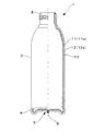
以下、本発明の実施の形態を実施例に沿って、図面を参照しながら説明する。図1は本発明の二重容器の第1実施例を部分的に縦断して示す正面図である。
この二重容器1は、ダイレクトブロー成形法により成形されたのもので、口筒部2、円筒状の胴部3、そして底部4を有する壜体である。
DESCRIPTION OF THE PREFERRED EMBODIMENTS Hereinafter, embodiments of the present invention will be described along examples with reference to the drawings. FIG. 1 is a front view showing a first embodiment of a double container according to the present invention partially longitudinally.
This
また、この二重容器1はポリエチレンテレフタレート(PET)系樹脂製の外層11からなる外容体11aとポリプロピレン(PP)系樹脂製の内層12からなる内容体12aから形成されており、口筒部2直下から底部5までの範囲では、外層11と内層12の間に空隙13が形成され、空隙13を挟んだ二重壁構造を有する。
The
次に、図1の二重容器1の成形方法について説明する。
この二重容器1は、多層押出し成形により相互に非接着性の外層と内層を積層した多層パリソンを成形し、この溶融状態の多層パリソンをブロー成形する、ダイレクトブロー成形方により成形することができる。
Next, a method for forming the
This
ここで、ブロー成形した成形品を金型から離型すると、全体的に成形収縮が開始、進行するが、特に、底部4の底面の底シール部5は金型のピンチオフ部により、大きな力で押圧状に形成された部分であるので、残留歪みが大きく、また比較的厚肉部分でもあるので、成形収縮の進行に伴ない、図1に示されるように、
外層11部分が内層12から部分的に剥離し、外層11部分に底割れ部6が形成される。
Here, when the blow-molded molded product is released from the mold, the molding shrinkage starts and proceeds as a whole. In particular, the
The
一方、本実施例のように外層11をPET系樹脂製、内層12をPP樹脂製として、内層12の成形収縮を外層11の成形収縮よりも大きくなるように材料選定すると、成形収縮の進行に伴なって、外層11と内層12の界面に両層を剥離するような力、すなわち剥離力が作用する。
そして、上記の底割れ部6、すなわち外層11と内層12が部分的に剥離した部分を起点として、この底割れ部6から外気を導入しながら、上記の剥離力の作用により剥離が容器全体に進展して図1に示すように口筒部2を除く領域で空隙13が形成され、この空隙13を挟んだ二重壁状態となる。
On the other hand, if the
Then, starting from the
口筒部2はブロー成形の際に大きく変形することなく形成される部分であるので、成形収縮後も剥離は進行せずに密着状態が保持されている。
Since the
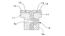
ここで、図2は底シール部5の参考例であり、構造底割れ部が形成されないようにしたものである。このように底シール部5を高さ幅を有する突条状として、底シール部5における外層11と内層12との圧着面積を大きくし、また複数の食い込み部5aを設けることにより、外層11と内層12との圧着面積をさらに増大させるばかりでなく、圧着面に平行する剪断力に対する抗力を飛躍的に高め、これにより底シール部5を底割れ部の発生し難い、機械的強度の高いものとすることができる。
Here, FIG. 2 is a reference example of the
そして、このような底シール部5を採用すると、底シール部5を前述したような剥離の起点として利用できないが、このような場合にでも、内層12の成形収縮を外層11の成形収縮にたいして十分大きくし、外層11と内層12の密着力を低くすること、
すなわち、界面に作用する剥離力が剥離強度より十分大きくなるように外層11と内層12に使用する合成樹脂材料と、ブロー成形条件を選択し、さらには外層11と内層12を比較的厚肉にして面剛性を大きくすること等により外層11と内層12の剥離の開始と進展は可能であり、略真空状の空隙13を形成できる。
If such a
That is, the synthetic resin material used for the
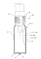
次に、図3は、本発明の二重容器の第2実施例である容器本体1aの口筒部2に手動押下げ式のポンプPを組付け固定したポンプ付容器40を部分的に縦断して示す正面図である。
このポンプ付容器40の容器本体1aは、第1実施例の二重容器と略同様な構成であるが、比較的薄肉の内層12で、内圧の減少により内方に萎み変形自在に減容変形する内容体12aを形成しており、デラミボトルとしての機能を発揮する。
Next, FIG. 3 shows a longitudinal section of a
The container
ただし、この容器本体1aは第1実施例の容器で説明したように、成形収縮により外層11部分の底割れ部6を起点として外層11と内層12の間に空隙13が形成された二重容器であり、従来のデラミボトルと違って成形後内容体12aを減圧状態にし、減容変形させて外層11と内層12を剥離し、またこの内容体12aを元の形状に戻すと云う工程を省略することができる。
However, as described in the container of the first embodiment, the
そして、内容液を内容体12aに充填した状態で、ポンプPを押し下げると内容液がポンプPの注出路を経て先端ノズルから注出される。そして、この注出量分だけ、内容体12aは萎み状に減容変形する。(図3中の2点鎖線で描いた状態を参照)
また、内容液の注出を終わって、ポンプPの押下げ状態を解除すると、内容体12aが減容変形した分、底割れ部6から外層11と内層12の間に外気が導入される。
When the pump P is pushed down in the state where the content liquid is filled in the
When the pumping state of the pump P is released after the content liquid has been poured out, the outside air is introduced between the
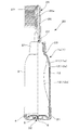
次に、図4は、本発明の二重容器の第3実施例である容器本体1aの上端部に櫛体25を組付け固定した櫛付き容器20を部分的に縦断して示す正面図である。この容器本体1aも第1実施例の二重容器と略同様な構成で、比較的薄肉の内層12で、内圧の減少により内方に萎み変形自在に減容変形する内容体12aを形成しており、スクイズタイプのデラミボトルとしての機能を発揮する。
Next, FIG. 4 is a front view showing the comb-equipped
容器本体1aの口筒部2にはキャップ体21がオーリング23を利用して密外嵌し、このキャップ体21を介して櫛体25が組付き固定しており、また、キャップ体21の頂壁には第1逆止弁体22が配設されている。
A
一方、底部5には有底円筒状のベースキャップ31が密外嵌している。このベースキャップ31の底壁には第2逆止弁体32が配設されている。
On the other hand, a bottomed
内容液を内容体12aに充填した状態で、手で押圧状にスクイズすると、第1逆止弁体22が開放して、内容液が櫛体25の注出流路26を上昇し、注出孔26aから櫛歯片27の間に注出される。そして、この注出量分だけ、内容体12aは萎み状に減容変形する。(図4中の2点鎖線で描いた状態を参照)
When the content liquid is filled in the
内容液の注出を終わって、押圧状態を解除すると外層11からなる外容体11aが弾性的な復元力により元の形状に復元するが、この際、第2逆止弁体32が開放して、内容体12aが減容変形した分、底割れ部6から外層11と内層12の間に外気が導入される。
When the content liquid is poured out and the pressed state is released, the
そして、再度、内容液の注出のために胴部4をスクイズする際には、第2逆止弁体32が閉状態となり、ベースキャップ31の密閉機能が機能して外層11と内層12の間の空気は密閉状態となるので、容易にスクイズ操作を繰り返すことができる。
And when squeezing the trunk | drum 4 again for the pouring of the content liquid, the 2nd
なお、上記第3実施例の櫛付き容器20では、底割れ部6から空気導入する構成として、第2逆止弁体32を有するベースキャップ31で底部4をシールする構成としているが、底シール部5を図2に示したような底割れのないタイプのものとし、口筒部2の外層11に、外層11と内層12の間に空気導入するための吸気孔を形成すると共に、キャップ体21の周壁を利用してこの吸気孔からの空気の流出を止める機能を有する第2逆止弁体を配設するような構成とすることもできる。
In the comb-equipped
以上、実施に沿って本発明の実施の形態を説明したが、本発明はこれら実施例に限定されるものではない。
たとえば、必要に応じて外層の外側や、内層の内側に他の層を積層することもできる。また、外層と内層に使用する合成樹脂の組み合わせは、両層の成形収縮と密着力を考慮してさまざまな組み合わせ態様とすることができる。また、主成分となる合成樹脂に他の合成樹脂をブレンドしたり、顔料やフィラーを分散させることにより、両層の成形収縮や密着力を調整することもできる。
As mentioned above, although embodiment of this invention was described along implementation, this invention is not limited to these Examples.
For example , if necessary, other layers can be laminated outside the outer layer or inside the inner layer. Moreover, the combination of the synthetic resin used for the outer layer and the inner layer can be various combinations in consideration of molding shrinkage and adhesion of both layers. Moreover, the molding shrinkage | contraction and adhesive force of both layers can also be adjusted by blending another synthetic resin with the synthetic resin used as a main component, or disperse | distributing a pigment and a filler.
本発明の合成樹脂製二重容器は特に内容体を外容体に挿入し組付け固定する必要もなく、通常のダイレクトブロー成形方法により容易に成形することができるものであり、デラミボトルとして、また二重壁を利用して加飾した容器として幅広い使用展開が期待される。 The double container made of the synthetic resin of the present invention does not require any particular contents to be inserted and fixed in the outer container, and can be easily molded by an ordinary direct blow molding method. A wide range of usage is expected as a container decorated with heavy walls.
1 ;二重容器
1a;容器本体
2 ;口筒部
3 ;胴部
4 ;底部
5 ;底シール部
5a;食い込み部
6;底割れ部
11;外層
11a;外容体
12;内層
12a;内容体
13;空隙
20;櫛付き容器
21;キャップ体
22;第1逆止弁体
23;オーリング
25;櫛体
26;注出流路
26a;注出孔
27;櫛歯片
31;ベースキャップ
32;第2逆止弁体
P ;ポンプ
DESCRIPTION OF
Claims (2)
相互に非接着性の合成樹脂からなる外層(11)と内層(12)を有し、
前記内層(12)の成形収縮を外層(11)の成形収縮よりも大きくなるように材料選定し、
前記内層(12)が、内圧の減少により内方に萎み変形自在に減容変形する内容体(12a)を形成しており、
底部(4)の底面にブロー割り金型のピンチオフ部により形成された底シール部(5)の外層(11)部分に、ダイレクトブロー成形に伴なう成形収縮により形成された底割れ部(6)を有し、
前記口筒部(2)の直下から底部(5)に至る全範囲において、前記外層(11)と内層(12)の間に、ダイレクトブロー成形に伴う該外層(11)と内層(12)の成形収縮の差により空隙(13)が剥離形成され、該空隙(13)を挟んだ二重壁構造を有することを特徴とする合成樹脂製二重容器。 A double container in the form of a casing having a mouth tube part (2), a body part (3), and a bottom part (4) by a direct blow molding method,
It has an outer layer (11) and an inner layer (12) made of synthetic resins that are non-adhesive to each other,
Material selection so that the molding shrinkage of the inner layer (12) is larger than the molding shrinkage of the outer layer (11),
The inner layer (12) forms a content body (12a) that is deflated and deformed in an inward direction due to a decrease in internal pressure.
The bottom crack part (6) formed by molding shrinkage accompanying direct blow molding on the outer layer (11) part of the bottom seal part (5) formed by the pinch-off part of the blow split mold on the bottom surface of the bottom part (4) )
Between the outer layer (11) and the inner layer (12), the outer layer (11) and the inner layer (12) associated with the direct blow molding are provided between the outer layer (11) and the inner layer (12) in the entire range from directly below the mouthpiece (2). A synthetic resin double container characterized in that the gap (13) is peeled off due to a difference in molding shrinkage and has a double wall structure sandwiching the gap (13).
The synthetic resin double container according to claim 1, wherein the outer layer (11) is made of polyethylene terephthalate resin and the inner layer (12) is made of polypropylene resin.
Priority Applications (8)
| Application Number | Priority Date | Filing Date | Title |
|---|---|---|---|
| JP2007172672A JP5267901B2 (en) | 2007-06-29 | 2007-06-29 | Synthetic resin double container by direct blow molding method |
| US12/452,272 US9067709B2 (en) | 2007-06-29 | 2008-06-19 | Synthetic resin double container molded by direct blow molding process |
| KR1020097006902A KR101493534B1 (en) | 2007-06-29 | 2008-06-19 | Double container of synthetic resin by direct blow molding method |
| EP08765744.1A EP2172400B1 (en) | 2007-06-29 | 2008-06-19 | A direct blow molding process for forming a double container of synthetic resin |
| AU2008272244A AU2008272244B2 (en) | 2007-06-29 | 2008-06-19 | Synthetic resin double container molded by direct blow molding process |
| PCT/JP2008/061189 WO2009004927A1 (en) | 2007-06-29 | 2008-06-19 | Double container of synthetic resin by direct blow molding method |
| CN2008800007747A CN101547836B (en) | 2007-06-29 | 2008-06-19 | Double container of synthetic resin by direct blow molding method |
| CA2692461A CA2692461C (en) | 2007-06-29 | 2008-06-19 | Synthetic resin double container molded by direct blow molding process |
Applications Claiming Priority (1)
| Application Number | Priority Date | Filing Date | Title |
|---|---|---|---|
| JP2007172672A JP5267901B2 (en) | 2007-06-29 | 2007-06-29 | Synthetic resin double container by direct blow molding method |
Publications (2)
| Publication Number | Publication Date |
|---|---|
| JP2009007060A JP2009007060A (en) | 2009-01-15 |
| JP5267901B2 true JP5267901B2 (en) | 2013-08-21 |
Family
ID=40225978
Family Applications (1)
| Application Number | Title | Priority Date | Filing Date |
|---|---|---|---|
| JP2007172672A Active JP5267901B2 (en) | 2007-06-29 | 2007-06-29 | Synthetic resin double container by direct blow molding method |
Country Status (8)
| Country | Link |
|---|---|
| US (1) | US9067709B2 (en) |
| EP (1) | EP2172400B1 (en) |
| JP (1) | JP5267901B2 (en) |
| KR (1) | KR101493534B1 (en) |
| CN (1) | CN101547836B (en) |
| AU (1) | AU2008272244B2 (en) |
| CA (1) | CA2692461C (en) |
| WO (1) | WO2009004927A1 (en) |
Cited By (7)
| Publication number | Priority date | Publication date | Assignee | Title |
|---|---|---|---|---|
| KR20170008783A (en) * | 2014-05-29 | 2017-01-24 | 교라꾸 가부시끼가이샤 | Laminated Release Container And Method For Manufacturing Same |
| WO2020262595A1 (en) | 2019-06-28 | 2020-12-30 | 日精エー・エス・ビー機械株式会社 | Apparatus for producing resin molded article, method for producing resin molded article, and resin molded article |
| WO2021060459A1 (en) | 2019-09-26 | 2021-04-01 | 日精エー・エス・ビー機械株式会社 | Method for producing delamination container and apparatus for producing delamination container |
| WO2021206088A1 (en) | 2020-04-06 | 2021-10-14 | 日精エー・エス・ビー機械株式会社 | Peeling container and method for manufacturing peeling container |
| WO2021206082A1 (en) | 2020-04-06 | 2021-10-14 | 日精エー・エス・ビー機械株式会社 | Delamination container manufacturing method and manufacturing device |
| WO2021206083A1 (en) | 2020-04-06 | 2021-10-14 | 日精エー・エス・ビー機械株式会社 | Method and device for manufacturing delamination container |
| WO2022030461A1 (en) | 2020-08-03 | 2022-02-10 | 日精エー・エス・ビー機械株式会社 | Resin container manufacturing method, die unit, and blow molding device |
Families Citing this family (32)
| Publication number | Priority date | Publication date | Assignee | Title |
|---|---|---|---|---|
| JP5267901B2 (en) | 2007-06-29 | 2013-08-21 | 株式会社吉野工業所 | Synthetic resin double container by direct blow molding method |
| KR200454300Y1 (en) * | 2009-03-16 | 2011-06-27 | (주)영진팩 | Blow molded multi container |
| CN104816877B (en) | 2009-07-09 | 2018-02-02 | 恩特格里斯公司 | The method of storage system and conveying material based on lining |
| EP2643094A4 (en) | 2010-11-23 | 2017-05-24 | Advanced Technology Materials, Inc. | Liner-based dispenser |
| JP5932847B2 (en) | 2011-03-01 | 2016-06-08 | アドバンスド テクノロジー マテリアルズ,インコーポレイテッド | Nested blow molded liner and overpack and method for making the same |
| JP6011929B2 (en) * | 2012-10-31 | 2016-10-25 | 株式会社吉野工業所 | Biaxial stretch blow molded container and manufacturing method thereof |
| CA2889206C (en) | 2012-10-31 | 2017-03-07 | Yoshino Kogyosho Co., Ltd. | Double container |
| JP6345062B2 (en) * | 2013-09-30 | 2018-06-20 | 株式会社吉野工業所 | Delamination container |
| CN109808979B (en) * | 2013-11-27 | 2023-12-22 | 京洛株式会社 | Laminated peeling container |
| MX370105B (en) * | 2014-02-06 | 2019-12-02 | Alpla Werke Alwin Lehner Gmbh & Co Kg | Plastic container produced in an extrusion blow molding method, in particular plastic bottle. |
| JP6407649B2 (en) * | 2014-09-30 | 2018-10-17 | 株式会社吉野工業所 | Delamination container |
| US10427821B2 (en) * | 2014-10-07 | 2019-10-01 | Kyoraku Co., Ltd. | Delaminated container manufacturing method and air leak inspection method for delaminated container |
| KR101655989B1 (en) * | 2014-10-20 | 2016-09-09 | (주)아모레퍼시픽 | Pump container for preventing the rest having a body with double structure |
| JP2016097978A (en) * | 2014-11-18 | 2016-05-30 | 株式会社平和化学工業所 | Double container for high viscous liquid |
| KR101611211B1 (en) * | 2015-04-24 | 2016-04-26 | 허재영 | The whole quantity consumption type tools |
| KR200481312Y1 (en) * | 2015-07-14 | 2016-09-09 | 마루니 코리아 주식회사 | Plastic dual container |
| TW201716297A (en) * | 2015-11-06 | 2017-05-16 | Well Max Beauty Lab Co Ltd | Dual-layered container and production method thereof can prevent the container from generating negative pressure through intake of the air gap and shrinkage deformation of the separation portion |
| CN105398637A (en) * | 2015-12-03 | 2016-03-16 | 中山汇伟塑胶工业有限公司 | Plastic bottle body with high structural strength |
| JP6737590B2 (en) * | 2015-12-09 | 2020-08-12 | 株式会社平和化学工業所 | Double container and manufacturing method thereof |
| JP6594771B2 (en) * | 2015-12-25 | 2019-10-23 | 株式会社吉野工業所 | Double container |
| ES2901614T3 (en) * | 2016-06-17 | 2022-03-23 | Dainippon Printing Co Ltd | Composite preform, process for manufacturing the same, composite container, process for manufacturing said composite container and heat-shrinkable plastic member |
| PT3299144T (en) * | 2016-09-26 | 2020-02-03 | Boehringer Ingelheim Int | Method for forming and / or testing a bag inside a container |
| JP6959498B2 (en) * | 2017-01-26 | 2021-11-02 | キョーラク株式会社 | Laminate peeling container |
| US10974885B2 (en) * | 2017-03-15 | 2021-04-13 | Kyoraku Co., Ltd. | Delaminatable container |
| US11155398B2 (en) * | 2017-04-05 | 2021-10-26 | Kikkoman Corporation | Dispensing container |
| US11388986B2 (en) | 2018-05-04 | 2022-07-19 | Maxro Llc | Liquid dispensing hairbrush systems and associated devices |
| CN113272233A (en) * | 2019-11-22 | 2021-08-17 | 深圳市德昌裕塑胶制品有限公司 | Flexible pipe container formed by multi-layer co-extrusion once |
| CN112674578B (en) * | 2020-12-06 | 2022-08-26 | 东莞合发包装制品有限公司 | Blow molding equipment and blow molding method |
| DE102021116278B4 (en) * | 2021-06-23 | 2024-02-29 | Gaplast Gmbh | Method and device for producing a container consisting of a rigid outer container and an easily deformable inner bag |
| IT202100017447A1 (en) * | 2021-07-02 | 2023-01-02 | Lumson Spa | Method of making a container for a dispensing device for a fluid substance, and dispensing device for that fluid substance |
| TWI777789B (en) * | 2021-09-27 | 2022-09-11 | 宏全國際股份有限公司 | Double-Wall Tubes, Double-Wall Containers, and Pneumatic Backstop Lid |
| TWI777788B (en) * | 2021-09-27 | 2022-09-11 | 宏全國際股份有限公司 | Double embryo, double bottle and air-operated backstop |
Family Cites Families (28)
| Publication number | Priority date | Publication date | Assignee | Title |
|---|---|---|---|---|
| US4071597A (en) * | 1974-09-13 | 1978-01-31 | Owens-Illinois, Inc. | Container with improved heat-shrunk cellular sleeve |
| US4261473A (en) * | 1975-12-17 | 1981-04-14 | Toyo Seikan Kaisha Limited | Molded container having wall composed of oriented resin blend |
| US4182457A (en) * | 1976-08-10 | 1980-01-08 | Toyo Seikan Kaisha Limited | Multilayer container |
| JPS57151314A (en) * | 1981-03-17 | 1982-09-18 | Yoshino Kogyosho Co Ltd | Synthetic resin made bottle and method for molding the same |
| CA1191006A (en) * | 1982-01-14 | 1985-07-30 | Sekisui Kaseihin Kogyo Kabushiki Kaisha | Sheet for forming sleeve and process for producing the same |
| DE8433745U1 (en) * | 1984-11-17 | 1985-03-28 | Kautex Werke Reinold Hagen AG, 5300 Bonn | With a sealable opening provided packaging |
| US4816305A (en) * | 1987-05-20 | 1989-03-28 | Mcneilab Inc. | Multi-walled tamper-proof container and method for enhancing tamper evidence |
| JPH0613099Y2 (en) * | 1988-02-18 | 1994-04-06 | キョーラク株式会社 | Squeeze container |
| JPH0748519Y2 (en) * | 1989-12-25 | 1995-11-08 | 大成化工株式会社 | Double container |
| JP2586294B2 (en) * | 1993-06-14 | 1997-02-26 | 東洋製罐株式会社 | Laminated release bottle and method for producing the same |
| JP3401519B2 (en) * | 1995-02-16 | 2003-04-28 | 株式会社吉野工業所 | Blow molding container and mold for molding the same |
| JPH09286084A (en) * | 1996-04-22 | 1997-11-04 | Tonen Chem Corp | Polythylenic resin laminate and large-scale clean container formed therefrom |
| AU724022B2 (en) * | 1996-05-30 | 2000-09-07 | Yoshino Kogyosho Co., Ltd. | Extrusion blow molded container having cylindrical drum portion and mold for shaping the container |
| CA2230768C (en) * | 1997-02-28 | 2007-02-13 | John W. Safian | Multilayer container package |
| DE19719252C2 (en) * | 1997-05-07 | 2002-10-31 | Valeo Klimatech Gmbh & Co Kg | Double-flow and single-row brazed flat tube evaporator for a motor vehicle air conditioning system |
| US6413600B1 (en) * | 1997-05-22 | 2002-07-02 | Plastipak Packaging, Inc. | Multi-layer container and preform and process for obtaining same |
| EP0893356A1 (en) * | 1997-07-23 | 1999-01-27 | The Procter & Gamble Company | Multilayer pressure resistant container |
| CA2412085A1 (en) * | 2000-06-27 | 2002-01-03 | Graham Packaging Company, L.P. | Preform and method for manufacturing a multi-layer, blown finish container |
| JP3817600B2 (en) * | 2000-07-31 | 2006-09-06 | 株式会社吉野工業所 | Synthetic resin housing |
| US6461699B1 (en) * | 2000-10-06 | 2002-10-08 | Plastipak Packaging, Inc. | Plastic container having a carbon-treated internal surface for non-carbonated food products |
| WO2003037725A1 (en) * | 2001-10-31 | 2003-05-08 | Yoshino Kogyosho Co., Ltd. | Blow-molded container |
| US6719173B2 (en) * | 2002-03-25 | 2004-04-13 | Owens-Brockway Plastic Products Inc. | Multilayer container package for dispensing a liquid product |
| US7293674B2 (en) * | 2002-04-30 | 2007-11-13 | Yoshino Kogyosho Co., Ltd. | Discharge container having a squeezable and deformable |
| JP4107585B2 (en) | 2003-05-30 | 2008-06-25 | 株式会社吉野工業所 | Replacement type double container |
| JP4416081B2 (en) * | 2004-01-30 | 2010-02-17 | ホーユー株式会社 | Delami bottle |
| FR2866321B1 (en) * | 2004-02-13 | 2007-05-18 | Lablabo | DEFORMABLE SOFT POUCH AND DEVICE FOR PACKAGING AND DISPENSING FLUID PRODUCTS. |
| JP4535259B2 (en) * | 2004-09-30 | 2010-09-01 | 株式会社吉野工業所 | Blow molding container |
| JP5267901B2 (en) | 2007-06-29 | 2013-08-21 | 株式会社吉野工業所 | Synthetic resin double container by direct blow molding method |
-
2007
- 2007-06-29 JP JP2007172672A patent/JP5267901B2/en active Active
-
2008
- 2008-06-19 EP EP08765744.1A patent/EP2172400B1/en active Active
- 2008-06-19 KR KR1020097006902A patent/KR101493534B1/en active IP Right Grant
- 2008-06-19 US US12/452,272 patent/US9067709B2/en active Active
- 2008-06-19 AU AU2008272244A patent/AU2008272244B2/en active Active
- 2008-06-19 WO PCT/JP2008/061189 patent/WO2009004927A1/en active Application Filing
- 2008-06-19 CN CN2008800007747A patent/CN101547836B/en active Active
- 2008-06-19 CA CA2692461A patent/CA2692461C/en active Active
Cited By (8)
| Publication number | Priority date | Publication date | Assignee | Title |
|---|---|---|---|---|
| KR20170008783A (en) * | 2014-05-29 | 2017-01-24 | 교라꾸 가부시끼가이샤 | Laminated Release Container And Method For Manufacturing Same |
| KR101884721B1 (en) * | 2014-05-29 | 2018-08-02 | 교라꾸 가부시끼가이샤 | Laminated Release Container And Method For Manufacturing Same |
| WO2020262595A1 (en) | 2019-06-28 | 2020-12-30 | 日精エー・エス・ビー機械株式会社 | Apparatus for producing resin molded article, method for producing resin molded article, and resin molded article |
| WO2021060459A1 (en) | 2019-09-26 | 2021-04-01 | 日精エー・エス・ビー機械株式会社 | Method for producing delamination container and apparatus for producing delamination container |
| WO2021206088A1 (en) | 2020-04-06 | 2021-10-14 | 日精エー・エス・ビー機械株式会社 | Peeling container and method for manufacturing peeling container |
| WO2021206082A1 (en) | 2020-04-06 | 2021-10-14 | 日精エー・エス・ビー機械株式会社 | Delamination container manufacturing method and manufacturing device |
| WO2021206083A1 (en) | 2020-04-06 | 2021-10-14 | 日精エー・エス・ビー機械株式会社 | Method and device for manufacturing delamination container |
| WO2022030461A1 (en) | 2020-08-03 | 2022-02-10 | 日精エー・エス・ビー機械株式会社 | Resin container manufacturing method, die unit, and blow molding device |
Also Published As
| Publication number | Publication date |
|---|---|
| AU2008272244A1 (en) | 2009-01-08 |
| US9067709B2 (en) | 2015-06-30 |
| EP2172400B1 (en) | 2013-08-28 |
| EP2172400A4 (en) | 2010-07-14 |
| US20100200586A1 (en) | 2010-08-12 |
| JP2009007060A (en) | 2009-01-15 |
| CA2692461C (en) | 2015-11-10 |
| AU2008272244B2 (en) | 2013-06-20 |
| CN101547836B (en) | 2013-07-31 |
| WO2009004927A1 (en) | 2009-01-08 |
| CN101547836A (en) | 2009-09-30 |
| KR101493534B1 (en) | 2015-02-13 |
| KR20100027088A (en) | 2010-03-10 |
| CA2692461A1 (en) | 2009-01-08 |
| EP2172400A1 (en) | 2010-04-07 |
Similar Documents
| Publication | Publication Date | Title |
|---|---|---|
| JP5267901B2 (en) | Synthetic resin double container by direct blow molding method | |
| JP4228362B2 (en) | Plastic container | |
| JP5440949B2 (en) | Blow molding container | |
| JP6407649B2 (en) | Delamination container | |
| EP3251960B1 (en) | Double-walled container | |
| JPH04267727A (en) | Multi-layer molded container and manufacture thereof | |
| US9919847B2 (en) | Integrated squeezable dispensing container | |
| JPH06239332A (en) | Multi-layer container | |
| JP5034452B2 (en) | Tube with check valve | |
| JP6638211B2 (en) | Plug with check valve and container having the plug | |
| JP2014091531A (en) | Blow-molded container | |
| US8226318B1 (en) | Tube with integral elastomeric applicator and method of manufacture therefor | |
| JP6553363B2 (en) | Double container | |
| JP2018108824A (en) | Double container | |
| JP7058919B2 (en) | Double container cap | |
| JP6651416B2 (en) | Double container | |
| JP2019172347A (en) | Double container | |
| JP2016069051A (en) | Delamination container | |
| JP2020001804A (en) | Double container cap and method for manufacturing double container cap | |
| JP2013249112A (en) | Blow molded container | |
| JP6641719B2 (en) | A stopper with a check valve, and a container equipped with the stopper | |
| CN105800050A (en) | Extrusion-convenient plastic bottle and bottle cap combination | |
| JP6746206B2 (en) | Double container | |
| JP6704651B2 (en) | Double container | |
| JP6476699B2 (en) | Container for dispensing |
Legal Events
| Date | Code | Title | Description |
|---|---|---|---|
| A621 | Written request for application examination |
Free format text: JAPANESE INTERMEDIATE CODE: A621 Effective date: 20100129 |
|
| A131 | Notification of reasons for refusal |
Free format text: JAPANESE INTERMEDIATE CODE: A131 Effective date: 20120515 |
|
| A521 | Request for written amendment filed |
Free format text: JAPANESE INTERMEDIATE CODE: A523 Effective date: 20120713 |
|
| A131 | Notification of reasons for refusal |
Free format text: JAPANESE INTERMEDIATE CODE: A131 Effective date: 20121030 |
|
| A521 | Request for written amendment filed |
Free format text: JAPANESE INTERMEDIATE CODE: A523 Effective date: 20121226 |
|
| TRDD | Decision of grant or rejection written | ||
| A01 | Written decision to grant a patent or to grant a registration (utility model) |
Free format text: JAPANESE INTERMEDIATE CODE: A01 Effective date: 20130423 |
|
| A61 | First payment of annual fees (during grant procedure) |
Free format text: JAPANESE INTERMEDIATE CODE: A61 Effective date: 20130425 |
|
| R150 | Certificate of patent or registration of utility model |
Free format text: JAPANESE INTERMEDIATE CODE: R150 Ref document number: 5267901 Country of ref document: JP Free format text: JAPANESE INTERMEDIATE CODE: R150 |