WO2021205968A1 - 耐摩耗部品 - Google Patents
耐摩耗部品 Download PDFInfo
- Publication number
- WO2021205968A1 WO2021205968A1 PCT/JP2021/014040 JP2021014040W WO2021205968A1 WO 2021205968 A1 WO2021205968 A1 WO 2021205968A1 JP 2021014040 W JP2021014040 W JP 2021014040W WO 2021205968 A1 WO2021205968 A1 WO 2021205968A1
- Authority
- WO
- WIPO (PCT)
- Prior art keywords
- base material
- material portion
- wear
- core
- tip
- Prior art date
- Legal status (The legal status is an assumption and is not a legal conclusion. Google has not performed a legal analysis and makes no representation as to the accuracy of the status listed.)
- Ceased
Links
Images


Classifications
-
- E—FIXED CONSTRUCTIONS
- E02—HYDRAULIC ENGINEERING; FOUNDATIONS; SOIL SHIFTING
- E02F—DREDGING; SOIL-SHIFTING
- E02F9/00—Component parts of dredgers or soil-shifting machines, not restricted to one of the kinds covered by groups E02F3/00 - E02F7/00
- E02F9/28—Small metalwork for digging elements, e.g. teeth scraper bits
- E02F9/2808—Teeth
- E02F9/285—Teeth characterised by the material used
-
- E—FIXED CONSTRUCTIONS
- E02—HYDRAULIC ENGINEERING; FOUNDATIONS; SOIL SHIFTING
- E02F—DREDGING; SOIL-SHIFTING
- E02F9/00—Component parts of dredgers or soil-shifting machines, not restricted to one of the kinds covered by groups E02F3/00 - E02F7/00
- E02F9/26—Indicating devices
- E02F9/267—Diagnosing or detecting failure of vehicles
-
- E—FIXED CONSTRUCTIONS
- E02—HYDRAULIC ENGINEERING; FOUNDATIONS; SOIL SHIFTING
- E02F—DREDGING; SOIL-SHIFTING
- E02F9/00—Component parts of dredgers or soil-shifting machines, not restricted to one of the kinds covered by groups E02F3/00 - E02F7/00
- E02F9/28—Small metalwork for digging elements, e.g. teeth scraper bits
- E02F9/2808—Teeth
- E02F9/2858—Teeth characterised by shape
Definitions
- This disclosure relates to wear-resistant parts.
- Patent Document 1 Japanese Patent Application Laid-Open No. 1-55370.
- Patent Document 2 Japanese Patent Application Laid-Open No. 2-176026
- Patent Document 3 Japanese Patent Application Laid-Open No. 9-192819
- wear-resistant parts such as tooth, tooth adapter, and ripper point are required to have improved wear resistance. It is one of the objects of the present disclosure to provide wear-resistant parts having improved wear resistance.
- the wear-resistant parts of the present disclosure include a metal base material portion and a core embedded in the base material portion and having a hardness higher than that of the base material portion.
- the core has a shape that follows the shape of at least a part of the surface of the base material portion.
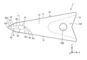
- FIG. 1 is a schematic perspective view showing the outer shape of the tooth according to the first embodiment.
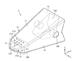
- FIG. 2 is a schematic perspective view showing the internal structure of the tooth according to the first embodiment.
- FIG. 3 is a schematic perspective view showing the structure of the core according to the first embodiment.
- FIG. 4 is a schematic plan view showing the internal structure of the tooth according to the first embodiment.
- FIG. 5 is a schematic side view showing the internal structure of the tooth according to the first embodiment.
- FIG. 6 is a schematic perspective view showing the outer shape of the tooth according to the second embodiment.
- FIG. 7 is a schematic perspective view showing the internal structure of the tooth according to the second embodiment.
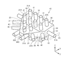
- FIG. 8 is a schematic perspective view showing the structure of the core according to the second embodiment.
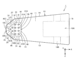
- FIG. 9 is a schematic plan view showing the internal structure of the tooth according to the second embodiment.
- FIG. 10 is a schematic side view showing the internal structure of the tooth according to the second embodiment.
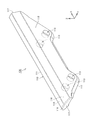
- FIG. 11 is a schematic perspective view showing the outer shape of the side protector according to the third embodiment.
- FIG. 12 is a schematic perspective view showing the internal structure of the side protector according to the third embodiment.
- the wear-resistant component according to the present disclosure includes a metal base material portion and a core embedded in the base material portion and having a hardness higher than that of the base material portion.
- the core has a shape that follows the shape of at least a part of the surface of the base material portion.
- a core having a shape that conforms to the shape of at least a part of the surface of the base material portion and having a hardness higher than that of the base material portion is embedded in the base material portion. Since the core has a shape that conforms to the shape of at least a part of the surface of the base metal portion, local wear is suppressed in the region where the core has a shape that conforms to the surface of the base metal portion. As a result, the wear resistance of the wear-resistant component is improved. As described above, according to the wear-resistant parts according to the present disclosure, it is possible to provide the wear-resistant parts having improved wear resistance.
- the core may include a main body portion and a bar material protruding from the main body portion. By doing so, the progress of wear in a region closer to the surface of the main body can be suppressed by the bar material.
- the bar may extend perpendicular to the surface of the base material.
- the tip of the bar may be exposed on the surface of the base material.
- the rod material (core) can contribute to the suppression of the progress of wear from the initial stage of the progress of wear.
- the tip (end face) of the bar is brought into contact with the wall surface defining the cavities of the mold to support the core, and then the metal constituting the base metal is melted. By pouring in the state, it becomes easy to arrange the core in an appropriate position.
- the base material portion may include a tip region that narrows toward the tip.
- the core may be arranged in the tip region and may have a shape corresponding to the outer shape of the tip region. By doing so, it is possible to effectively suppress the wear of the tip region.
- FIG. 1 is a schematic perspective view showing the outer shape of the tooth according to the first embodiment.
- FIG. 2 is a schematic perspective view showing the internal structure of the tooth according to the first embodiment.
- FIG. 2 corresponds to a state in which the inside of the tooth of FIG. 1 is seen through.
- FIG. 3 is a schematic perspective view showing the structure of the core according to the first embodiment.
- FIG. 4 is a schematic plan view showing the internal structure of the tooth according to the first embodiment.
- FIG. 5 is a schematic side view showing the internal structure of the tooth according to the first embodiment.
- the X-axis direction corresponds to the longitudinal direction (tip-base end direction) of the tooth.
- the Y-axis direction corresponds to the thickness direction of the tooth.
- the Z-axis direction corresponds to the width direction of the tooth.
- FIG. 4 is a plan view in the XX plane.
- FIG. 5 is a side view in the XY plane.
- the base material portion 10 constituting the surface of the tooth 1 in the first embodiment includes a tip end 10C and a base end 19.
- the base material portion 10 includes a first surface 11, a second surface 12, a third surface 13, a fourth surface 14, a fifth surface 15, a sixth surface 16, a seventh surface 17, and an eighth surface. Includes surface 18.
- the first surface 11 and the second surface 12 are connected to the base end 19, respectively.
- the first surface 11 and the second surface 12 are arranged at intervals in the Y-axis direction so that the distance between them decreases as they approach the tip 10C.
- the fifth surface 15 and the sixth surface 16 connect the first surface 11 and the second surface 12 to the tip 10C, respectively.
- the fifth surface 15 and the sixth surface 16 are arranged so that the distance between them decreases as they approach the tip 10C.
- the angle formed by the fifth surface 15 and the sixth surface 16 is larger than the angle formed by the first surface 11 and the second surface 12.
- the third surface 13 and the fourth surface 14 are connected to the base end 19, respectively.
- the third surface 13 and the fourth surface 14 are arranged at intervals in the Z-axis direction so that the distance between the third surface 13 and the fourth surface 14 becomes smaller as they approach the tip 10C.
- the seventh surface 17 and the eighth surface 18 connect the fourth surface 14, the third surface 13, and the tip 10C, respectively.
- the seventh surface 17 and the eighth surface 18 are arranged so that the distance between them decreases as they approach the tip 10C.
- the angle formed by the seventh surface 17 and the eighth surface 18 is larger than the angle formed by the third surface 13 and the fourth surface 14.
- the tip 10C is a surface (region) extending linearly in the Z-axis direction.
- a recess 10A is formed at the base end 19 toward the tip (recessed in the X-axis direction).
- the base material portion 10 is formed with a through hole 10B penetrating from the third surface 13 to the fourth surface 14.
- the through hole 10B intersects the recess 10A. That is, the through hole 10B communicates with the recess 10A.
- Tooth 1 is attached to, for example, a bucket of a hydraulic excavator (not shown). More specifically, a tooth adapter (not shown) is attached to the outer edge of the opening of the bucket of the hydraulic excavator. The tip of the tooth adapter is inserted into the recess 10A formed at the base end 19 of the tooth 1 (base material portion 10). A pin (not shown) is inserted into the through hole 10B so as to penetrate the through hole 10B. As a result, the tooth 1 is attached to the bucket via the tooth adapter.
- tooth 1 includes a metal base material portion 10 and a core 40 embedded in the base material portion 10.
- the metal constituting the base material portion 10 for example, cast steel can be adopted.
- the cast steel that can be used is not particularly limited as long as it has appropriate wear resistance.
- low alloys such as Cr-Mo-based cast steel, Cr-Mo-V-W-based cast steel, Cr-Mo-Ni-based cast steel, high Mn-based cast steel, boron cast steel, Cr-Mo-V-based cast steel, and high Cr-based cast steel. Cast steel may be adopted.
- cast steel having a component composition such as carbon steel for machine structure or alloy steel for machine structure (for example, S45C, SCM435, SMn steel containing an equivalent amount of carbon, SCr steel, SCM steel, etc.) specified in JIS standards. May be adopted.
- cast iron having a higher carbon content than cast steel may be used as the metal constituting the base metal portion 10.
- the core 40 has a higher hardness than the base material portion 10.
- the core 40 may be a sintered body of particles or powder of a hard material such as high-speed tool steel or cemented carbide. Molding of the core 40 before sintering may be performed by, for example, a 3D printer.
- the core 40 may be manufactured by a method such as rolling (including irregular rolling), cutting, forging, casting, etc., instead of or in combination with sintering. Further, a build-up layer containing particles or powder of high-speed tool steel, cemented carbide or the like may be formed on the surface of the core 40.
- the surfaces (outer shape) of the core 40 are the first surface 41, the second surface 42, the third surface 43, the fourth surface 44, and the fifth surface 45.
- the sixth surface 46, the seventh surface 47, the eighth surface 48, the ninth surface 49, and the tip 40C are included.
- the first surface 41 is along the first surface 11 of the base material portion 10.
- the second surface 42 is along the second surface 12 of the base material portion 10.
- the third surface 43 is along the third surface 13 of the base material portion 10.
- the fourth surface 44 is along the fourth surface 14 of the base material portion 10.
- the fifth surface 45 is along the fifth surface 15 of the base material portion 10.
- the sixth surface 46 is along the sixth surface 16 of the base material portion 10.
- the seventh surface 47 is along the seventh surface 17 of the base material portion 10.
- the eighth surface 48 is along the eighth surface 18 of the base material portion 10.
- the tip 40C is along the tip 10C of the base material portion 10 (tooth 1).
- the ninth surface 49 is a surface (a surface facing the base end 19) opposite to the tip 40C in the X-axis direction.
- the base material portion 10 includes a tip region 10D that narrows toward the tip 10C.
- the core 40 is arranged in the tip region 10D and has a shape corresponding to the outer shape of the tip region 10D. That is, the outer shape of the core 40 is a shape that follows the outer shape of the tip region 10D. From another point of view, the outer shape of the core 40 corresponds to a shape in which the outer shape of the tip region 10D is substantially similar and reduced.
- tooth 1 of the first embodiment a core 40 having a shape that follows the shape of the surface of the base material portion 10 and having a hardness higher than that of the base material portion 10 is embedded in the base material portion 10. As a result, local wear is suppressed in the region where the core 40 has a shape along the surface of the base material portion 10. As a result, the wear resistance of the tooth 1 is improved. As described above, the tooth 1 in the first embodiment is an wear-resistant component having improved wear resistance.
- the base material portion 10 of the tooth 1 in the first embodiment includes a tip region 10D that narrows toward the tip 10C.
- the core 40 is arranged in the tip region 10D and has a shape corresponding to the outer shape of the tip region 10D. Therefore, it is possible to effectively suppress the wear of the tip region 10D.
- the core 40 has a three-dimensional lattice-like structure formed of a plurality of rod-shaped members, and may be arranged inside a frame portion embedded in the base material portion 10. Then, at least a part of the end faces of the rod-shaped members may be exposed on the surface of the base material portion 10. By doing so, when the tooth 1 is manufactured by casting, the end face of the rod-shaped member constituting the skeleton is brought into contact with the wall surface defining the cabidi of the mold to support the skeleton and inside the skeleton. By arranging the core 40 and then pouring the metal constituting the base material portion 10 in a molten state, it becomes easy to arrange the core 40 at an appropriate position.
- the hardness of the skeleton portion is preferably higher than that of the base material portion 10 (about HV500).
- the hardness of the skeleton portion may be the same as that of the base material portion 10 or may be smaller than that of the base material portion 10.
- the material constituting the skeleton may be, for example, mild steel.
- the tooth as a wear-resistant component of the second embodiment basically has the same structure as that of the first embodiment and has the same effect. However, the tooth of the second embodiment is different from the first embodiment in the following points.
- FIG. 6 is a schematic perspective view showing the outer shape of the tooth according to the second embodiment.
- FIG. 7 is a schematic perspective view showing the internal structure of the tooth according to the second embodiment.
- FIG. 7 corresponds to a state in which the inside of the tooth of FIG. 6 is seen through.
- FIG. 8 is a schematic perspective view showing the structure of the core according to the second embodiment.
- FIG. 9 is a schematic plan view showing the internal structure of the tooth according to the second embodiment.
- FIG. 10 is a schematic side view showing the internal structure of the tooth according to the second embodiment.
- the X-axis direction corresponds to the longitudinal direction (tip-base end direction) of the tooth.
- the Y-axis direction corresponds to the thickness direction of the tooth.
- the Z-axis direction corresponds to the width direction of the tooth.
- FIG. 9 is a plan view in the XX plane.
- FIG. 10 is a side view in the XY plane.
- the core 40 of the second embodiment includes a main body portion 30 and a bar member 31 protruding from the main body portion 30.
- a plurality of rods 31 project from the main body 30.
- the plurality of rods 31 project radially from the main body 30.
- the main body 30 has the same shape as the core 40 of the first embodiment.
- the surfaces (outer shape) of the main body 30 are the first surface 41, the second surface 42, the third surface 43, the fourth surface 44, the fifth surface 45, the sixth surface 46, and the seventh surface. 47, the eighth surface 48, the ninth surface 49, and the tip 40C are included.
- the first surface 41 is along the first surface 11 of the base material portion 10.
- the second surface 42 is along the second surface 12 of the base material portion 10.
- the third surface 43 is along the third surface 13 of the base material portion 10.
- the fourth surface 44 is along the fourth surface 14 of the base material portion 10.
- the fifth surface 45 is along the fifth surface 15 of the base material portion 10.
- the sixth surface 46 is along the sixth surface 16 of the base material portion 10.
- the seventh surface 47 is along the seventh surface 17 of the base material portion 10.
- the eighth surface 48 is along the eighth surface 18 of the base material portion 10.
- the tip 40C is along the tip 10C of the base material portion 10 (tooth 1).
- the ninth surface 49 is a surface (a surface facing the base end 19) opposite to the tip 40C in the X-axis direction.
- the bar 31 projects from the surface of the main body 30 along the surface of the tip region 10D. As described above, since the core 40 includes the bar 31, it is possible for the bar 31 to suppress the progress of wear in a region closer to the surface of the base material portion 10.
- the tip (end face 31A) of the bar 31 of the second embodiment is exposed on the surface of the base material portion 10.
- the end faces 31A of at least a part of the bars 31 (end faces 31A of all the bars 31 in the present embodiment) of the plurality of bars 31 are exposed on the surface of the base material portion 10.
- Each bar 31 projects from the main body 30 in a direction perpendicular to the surface of the base material portion 10 on which the end surface 31A is exposed.
- the bar 31 has a solid cylindrical shape.
- the end face 31A has a circular or elliptical shape.
- the first to eighth surfaces 11 to 18 and the tip 10C and the end surface 31A exposed in these are flush with each other. That is, the end faces 31A of the plurality of bar members 31 are included in a flat surface or a curved surface along the surface of the base material portion 10.
- the outer shape of the core 40 defined by the end surface 31A of the bar 31 has a shape corresponding to the surface of the base material portion 10 (the surface of the tip region 10D).
- the outer shape of the core 40 is the first surface 21, the second surface 22, the third surface 23, the fourth surface 24, the fifth surface 25, the sixth surface 26, the seventh surface 27, and the fourth surface. It includes an eight surface 28 and a tip surface 20C.
- the first surface 21 is along the first surface 11 of the base material portion 10.
- the second surface 22 is along the second surface 12 of the base material portion 10.
- the third surface 23 is along the third surface 13 of the base material portion 10.
- the fourth surface 24 is along the fourth surface 14 of the base material portion 10.
- the fifth surface 25 is along the fifth surface 15 of the base material portion 10.
- the sixth surface 26 is along the sixth surface 16 of the base material portion 10.
- the seventh surface 27 is along the seventh surface 17 of the base material portion 10.
- the eighth surface 28 is along the eighth surface 18 of the base material portion 10.
- the tip 20C is along the tip 10C of the base material portion 10 (tooth 1).
- the core 40 can contribute to suppressing the progress of wear from the initial stage of wear progress. Further, when the tooth 1 is manufactured by casting, the end face 31A of the rod member 31 constituting the core 40 is brought into contact with the wall surface defining the cavities of the mold to support the core 40, and then the base metal portion 10 is formed. By pouring the metal in a molten state, it becomes easy to arrange the core 40 at an appropriate position.
- the side protector as the wear-resistant component of the third embodiment has a structure in which the same configuration as that of the tooth of the first embodiment is applied to the side protector.
- FIG. 11 is a schematic perspective view showing the outer shape of the side protector according to the third embodiment.
- FIG. 12 is a schematic perspective view showing the internal structure of the side protector according to the third embodiment.
- FIG. 12 corresponds to a state in which the inside of the side protector of FIG. 11 is seen through.
- the side protector 100 in the third embodiment includes a main body 111 and a pair of legs 112 connected to the main body 111.
- the main body 111 has a rod-like shape extending along the X-axis direction (first direction).
- the pair of leg portions 112 are connected to both ends of the main body portion 111 in the width direction (Y-axis direction as the second direction).
- the leg portion 112 is arranged so as to rise from the main body portion 111 along the Z-axis direction (third direction).
- the leg portion 112 has a plate-like shape extending along the XX plane.
- the pair of legs 112 are arranged parallel to each other.
- Each of the pair of leg portions 112 is formed with a pair of through holes 113 penetrating the leg portions 112 in the thickness direction at intervals in the X-axis direction.
- the through holes 113 of the pair of legs 112 are arranged at the same position in the X-axis direction.
- the side protector 100 is a wear-resistant component that suppresses wear of the outer edge portion by being attached to an outer edge portion that surrounds an opening of a bucket (not shown) of a hydraulic excavator, for example.
- the side protector 100 is inserted into the bucket by inserting a fixing member such as a pin into each through hole 113 in a state where the plate-shaped portion forming the outer edge of the opening of the bucket is inserted between the pair of legs 112. On the other hand, it is fixed.
- the base material portion 110 forming the surface of the side protector 100 in the third embodiment includes a pair of end faces 117 which are planes forming both ends in the longitudinal direction (X-axis direction) of the main body portion 111.
- the base material portion 110 extends in the X-axis direction, is connected to both ends in the width direction (Y direction) of the top surface 115, which is a plane connecting the pair of end faces 117, and is inclined with respect to the top surface 115.
- the top surface 115 is a surface along the XY plane.
- the side surface 118 is a surface along the XX plane. That is, the plane including the top surface 115 and the plane including the side surface 118 are orthogonal to each other.
- the side protector 100 includes a metal base material portion 110 and a core 140 arranged inside the base material portion 110 and having a hardness higher than that of the base material portion 110.
- the metal constituting the base metal portion 10 for example, cast steel or cast iron can be adopted as in the above-described first and second embodiments.
- the core 140 may be made of the same material as in the first embodiment.
- the surface (outer shape) of the core 140 includes a top surface 141, a pair of inclined surfaces 142, and a pair of end surfaces 143.
- the top surface 141 is along the top surface 115 of the base material portion 110.
- the pair of inclined surfaces 142 are along the pair of inclined surfaces 116 of the base material portion 110.
- the core 140 is arranged in the base material portion 110 corresponding to the main body portion 111, and has a shape corresponding to the outer shape of the main body portion 111.
- the side protector 100 of the third embodiment By providing the side protector 100 of the third embodiment, even if the base material portion 110 is worn, the progress of wear can be suppressed by the core 140 having high hardness. Further, in the third embodiment, since the core 140 has a shape that follows the shape of at least a part of the surface of the base material portion 110, the core 140 has a shape that follows the surface of the base material portion 110. In, the progress of local wear is suppressed. As described above, the side protector 100 in the third embodiment is an wear-resistant component having improved wear resistance.
- the tooth and the side protector have been described as an example of the wear-resistant parts of the present disclosure, but the wear-resistant parts of the present disclosure are not limited to this.
- the wear-resistant parts of the present disclosure can be applied to various parts that require wear resistance by being used for applications such as contact with earth and sand, rocks, and the like.
- the wear-resistant parts of the present disclosure are particularly preferably applied to parts in which wear at the tip is a problem, such as the tooth and side protectors, as well as tooth adapters, ripper points, track chain members constituting tracks, and lug bars. Can be done.
- the wear resistance of the present disclosure is also applied to the corner guard (a part attached to the bottom corner) and the lip shroud (a part attached to the bucket lip), which are parts that suppress the progress of partial wear of the bucket as in the case of the side protector. Parts can be applied. Further, in the above description, the application of the wear-resistant parts of the present disclosure to the parts of the bucket of the hydraulic excavator has been described, but the wear-resistant parts of the present disclosure can be similarly applied to the parts of the bucket of the wheel loader.
Landscapes
- Engineering & Computer Science (AREA)
- Mining & Mineral Resources (AREA)
- Civil Engineering (AREA)
- General Engineering & Computer Science (AREA)
- Structural Engineering (AREA)
- Component Parts Of Construction Machinery (AREA)
- Braking Arrangements (AREA)
- Macromolecular Compounds Obtained By Forming Nitrogen-Containing Linkages In General (AREA)
Priority Applications (5)
| Application Number | Priority Date | Filing Date | Title |
|---|---|---|---|
| CN202180022647.2A CN115335573B (zh) | 2020-04-09 | 2021-03-31 | 耐磨耗部件 |
| AU2021251552A AU2021251552B2 (en) | 2020-04-09 | 2021-03-31 | Wear-resistant component |
| DE112021000685.1T DE112021000685T5 (de) | 2020-04-09 | 2021-03-31 | Verschleißbeständiges Bauteil |
| US17/913,396 US12460393B2 (en) | 2020-04-09 | 2021-03-31 | Wear resistant component |
| JP2022514437A JPWO2021205968A1 (https=) | 2020-04-09 | 2021-03-31 |
Applications Claiming Priority (2)
| Application Number | Priority Date | Filing Date | Title |
|---|---|---|---|
| JP2020-070360 | 2020-04-09 | ||
| JP2020070360 | 2020-04-09 |
Publications (1)
| Publication Number | Publication Date |
|---|---|
| WO2021205968A1 true WO2021205968A1 (ja) | 2021-10-14 |
Family
ID=78024019
Family Applications (1)
| Application Number | Title | Priority Date | Filing Date |
|---|---|---|---|
| PCT/JP2021/014040 Ceased WO2021205968A1 (ja) | 2020-04-09 | 2021-03-31 | 耐摩耗部品 |
Country Status (6)
| Country | Link |
|---|---|
| US (1) | US12460393B2 (https=) |
| JP (1) | JPWO2021205968A1 (https=) |
| CN (1) | CN115335573B (https=) |
| AU (1) | AU2021251552B2 (https=) |
| DE (1) | DE112021000685T5 (https=) |
| WO (1) | WO2021205968A1 (https=) |
Cited By (1)
| Publication number | Priority date | Publication date | Assignee | Title |
|---|---|---|---|---|
| US20230332383A1 (en) * | 2022-04-13 | 2023-10-19 | Hensley Industries, Inc. | Reinforced wear member |
Families Citing this family (1)
| Publication number | Priority date | Publication date | Assignee | Title |
|---|---|---|---|---|
| JP7503517B2 (ja) * | 2021-03-31 | 2024-06-20 | 株式会社小松製作所 | 耐摩耗部品 |
Citations (4)
| Publication number | Priority date | Publication date | Assignee | Title |
|---|---|---|---|---|
| JPS495202U (https=) * | 1972-04-13 | 1974-01-17 | ||
| JPS56121766U (https=) * | 1980-02-13 | 1981-09-17 | ||
| JPH0470387U (https=) * | 1990-10-23 | 1992-06-22 | ||
| KR20100131909A (ko) * | 2009-06-08 | 2010-12-16 | 최학희 | 굴착기 버켓트용 팁 및 그 제조방법 |
Family Cites Families (28)
| Publication number | Priority date | Publication date | Assignee | Title |
|---|---|---|---|---|
| AU414770B2 (en) * | 1966-11-14 | 1971-07-06 | Gerald Alger Petersen | Digging tooth with corrugated crosssection |
| US3932952A (en) * | 1973-12-17 | 1976-01-20 | Caterpillar Tractor Co. | Multi-material ripper tip |
| JPS6455370A (en) | 1987-08-26 | 1989-03-02 | Sumitomo Jukikai Chutan Kk | Production of composite material for drilling tooth |
| JP2596106B2 (ja) * | 1988-12-27 | 1997-04-02 | 住友重機械鋳鍛株式会社 | 複合掘削ツース |
| FR2667088B1 (fr) | 1990-09-20 | 1994-10-14 | Technogenia Sa | Dent pour outil d'excavation. |
| CN2091895U (zh) * | 1991-03-02 | 1992-01-01 | 本溪冶金专科学校 | 一种耐磨铲齿 |
| US5224282A (en) * | 1992-01-21 | 1993-07-06 | Harnischfeger Corporation | Tooth assembly for a digger bucket |
| FR2708973B1 (fr) * | 1993-03-29 | 1995-10-27 | Pasqualini Charles | Dispositif et procédé de liaison entre des dents amovibles et des adapteurs formés aux extrémités d'outils et réceptacles en usage sur les engins de travaux publics. |
| JP2852867B2 (ja) * | 1994-05-13 | 1999-02-03 | 株式会社小松製作所 | 耐摩耗部品の製造方法及びその耐摩耗部品 |
| JPH09192819A (ja) | 1996-01-09 | 1997-07-29 | Mitsubishi Steel Mfg Co Ltd | 耐摩耗性複合材鋳造品の製造方法 |
| JP3676530B2 (ja) * | 1996-12-26 | 2005-07-27 | 株式会社小松製作所 | 掘削バケット装置 |
| JP3380723B2 (ja) * | 1997-10-30 | 2003-02-24 | 新キャタピラー三菱株式会社 | 掘削用切刃およびその製造方法 |
| JP4190271B2 (ja) * | 2002-12-06 | 2008-12-03 | 株式会社小松製作所 | 掘削用切刃 |
| US8241761B2 (en) * | 2007-08-15 | 2012-08-14 | Mikhail Garber | Abrasion and impact resistant composite castings for working in condition of wear and high dynamic loads |
| WO2010136055A1 (en) | 2009-05-29 | 2010-12-02 | Metalogenia S.A. | Wear element for earth working machine with enhanced wear resistance |
| CN102482862B (zh) * | 2009-05-29 | 2015-03-18 | 麦塔洛吉尼亚股份有限公司 | 耐磨性增强的耐磨部件 |
| CN201459801U (zh) * | 2009-09-10 | 2010-05-12 | 佳木斯大学 | 一种镶铸复合金属耐磨铲齿 |
| CN102182223B (zh) * | 2011-03-29 | 2013-05-01 | 中国地质大学(北京) | 一种挖掘机复合斗齿及其制备方法 |
| JP5373169B1 (ja) * | 2012-10-10 | 2013-12-18 | 株式会社小松製作所 | 掘削爪および掘削爪用ボディ |
| WO2015017894A1 (en) * | 2013-08-09 | 2015-02-12 | Mining Innovations Australia Pty Ltd | Wear-resistant armour for mining machinery |
| CN204163141U (zh) * | 2014-09-03 | 2015-02-18 | 李贵友 | 镶嵌式耐磨合金斗齿 |
| CN105457729B (zh) * | 2015-12-16 | 2016-10-05 | 山东天瑞重工有限公司 | 一种镶嵌合金的高频器斗齿 |
| CN205591275U (zh) * | 2016-04-21 | 2016-09-21 | 张景志 | 一种复合镶铸电铲斗齿 |
| JP6804143B2 (ja) | 2016-09-30 | 2020-12-23 | 株式会社小松製作所 | 耐土砂摩耗部品およびその製造方法 |
| CN207878544U (zh) * | 2018-01-16 | 2018-09-18 | 朝阳市多元合金铸造有限责任公司 | 一种挖掘电铲斗齿 |
| EP3563951A1 (fr) | 2018-05-04 | 2019-11-06 | Magotteaux International S.A. | Dent composite avec insert tronconique |
| JP6857407B2 (ja) | 2018-10-31 | 2021-04-14 | シーレックス株式会社 | タイヤ用粘着シート |
| WO2021168297A1 (en) * | 2020-02-19 | 2021-08-26 | Esco Group Llc | Wear member |
-
2021
- 2021-03-31 CN CN202180022647.2A patent/CN115335573B/zh active Active
- 2021-03-31 US US17/913,396 patent/US12460393B2/en active Active
- 2021-03-31 AU AU2021251552A patent/AU2021251552B2/en active Active
- 2021-03-31 WO PCT/JP2021/014040 patent/WO2021205968A1/ja not_active Ceased
- 2021-03-31 DE DE112021000685.1T patent/DE112021000685T5/de active Pending
- 2021-03-31 JP JP2022514437A patent/JPWO2021205968A1/ja active Pending
Patent Citations (4)
| Publication number | Priority date | Publication date | Assignee | Title |
|---|---|---|---|---|
| JPS495202U (https=) * | 1972-04-13 | 1974-01-17 | ||
| JPS56121766U (https=) * | 1980-02-13 | 1981-09-17 | ||
| JPH0470387U (https=) * | 1990-10-23 | 1992-06-22 | ||
| KR20100131909A (ko) * | 2009-06-08 | 2010-12-16 | 최학희 | 굴착기 버켓트용 팁 및 그 제조방법 |
Cited By (3)
| Publication number | Priority date | Publication date | Assignee | Title |
|---|---|---|---|---|
| US20230332383A1 (en) * | 2022-04-13 | 2023-10-19 | Hensley Industries, Inc. | Reinforced wear member |
| CN116905608A (zh) * | 2022-04-13 | 2023-10-20 | 汉斯莱产业股份有限公司 | 增强磨损构件 |
| EP4508279A4 (en) * | 2022-04-13 | 2026-04-15 | Hensley Ind Inc | REINFORCED WEAR ELEMENT |
Also Published As
| Publication number | Publication date |
|---|---|
| DE112021000685T5 (de) | 2023-01-05 |
| JPWO2021205968A1 (https=) | 2021-10-14 |
| US12460393B2 (en) | 2025-11-04 |
| AU2021251552B2 (en) | 2024-02-08 |
| AU2021251552A1 (en) | 2022-09-29 |
| CN115335573A (zh) | 2022-11-11 |
| CN115335573B (zh) | 2024-08-20 |
| US20230167630A1 (en) | 2023-06-01 |
Similar Documents
| Publication | Publication Date | Title |
|---|---|---|
| CA1309741C (en) | Composite excavating tooth | |
| US8959806B2 (en) | Rolled steel lip for an excavator bucket | |
| CN108291393B (zh) | 用于工具适配器的改进加强系统 | |
| CN103562467B (zh) | 地面接合工具齿尖 | |
| CN109072591B (zh) | 耐磨部件及其制造方法 | |
| WO2021205968A1 (ja) | 耐摩耗部品 | |
| CN103874808B (zh) | 挖掘爪及挖掘爪用主体 | |
| WO2021205969A1 (ja) | 耐摩耗部品 | |
| AU2009203887A1 (en) | Wear resistant components | |
| WO1995031304A1 (en) | Method for casting wear resistant parts | |
| JP7503517B2 (ja) | 耐摩耗部品 | |
| CN115103946A (zh) | 耐磨构件 | |
| CN113614321A (zh) | 用于挖掘铲斗的唇缘 | |
| CN115427637B (zh) | 用于作业机具的拐角段和拐角护罩 | |
| US10745891B2 (en) | Tooth adapter and bucket |
Legal Events
| Date | Code | Title | Description |
|---|---|---|---|
| 121 | Ep: the epo has been informed by wipo that ep was designated in this application |
Ref document number: 21785173 Country of ref document: EP Kind code of ref document: A1 |
|
| WWE | Wipo information: entry into national phase |
Ref document number: 2021251552 Country of ref document: AU |
|
| ENP | Entry into the national phase |
Ref document number: 2022514437 Country of ref document: JP Kind code of ref document: A |
|
| ENP | Entry into the national phase |
Ref document number: 2021251552 Country of ref document: AU Date of ref document: 20210331 Kind code of ref document: A |
|
| 122 | Ep: pct application non-entry in european phase |
Ref document number: 21785173 Country of ref document: EP Kind code of ref document: A1 |
|
| WWG | Wipo information: grant in national office |
Ref document number: 17913396 Country of ref document: US |