WO2021205723A1 - 内燃機関制御装置 - Google Patents
内燃機関制御装置 Download PDFInfo
- Publication number
- WO2021205723A1 WO2021205723A1 PCT/JP2021/003644 JP2021003644W WO2021205723A1 WO 2021205723 A1 WO2021205723 A1 WO 2021205723A1 JP 2021003644 W JP2021003644 W JP 2021003644W WO 2021205723 A1 WO2021205723 A1 WO 2021205723A1
- Authority
- WO
- WIPO (PCT)
- Prior art keywords
- sub
- internal combustion
- combustion engine
- chamber
- engine
- Prior art date
- Legal status (The legal status is an assumption and is not a legal conclusion. Google has not performed a legal analysis and makes no representation as to the accuracy of the status listed.)
- Ceased
Links
Images








Classifications
-
- F—MECHANICAL ENGINEERING; LIGHTING; HEATING; WEAPONS; BLASTING
- F02—COMBUSTION ENGINES; HOT-GAS OR COMBUSTION-PRODUCT ENGINE PLANTS
- F02B—INTERNAL-COMBUSTION PISTON ENGINES; COMBUSTION ENGINES IN GENERAL
- F02B19/00—Engines characterised by precombustion chambers
- F02B19/12—Engines characterised by precombustion chambers with positive ignition
-
- F—MECHANICAL ENGINEERING; LIGHTING; HEATING; WEAPONS; BLASTING
- F02—COMBUSTION ENGINES; HOT-GAS OR COMBUSTION-PRODUCT ENGINE PLANTS
- F02D—CONTROLLING COMBUSTION ENGINES
- F02D29/00—Controlling engines, such controlling being peculiar to the devices driven thereby, the devices being other than parts or accessories essential to engine operation, e.g. controlling of engines by signals external thereto
- F02D29/06—Controlling engines, such controlling being peculiar to the devices driven thereby, the devices being other than parts or accessories essential to engine operation, e.g. controlling of engines by signals external thereto peculiar to engines driving electric generators
-
- F—MECHANICAL ENGINEERING; LIGHTING; HEATING; WEAPONS; BLASTING
- F02—COMBUSTION ENGINES; HOT-GAS OR COMBUSTION-PRODUCT ENGINE PLANTS
- F02D—CONTROLLING COMBUSTION ENGINES
- F02D45/00—Electrical control not provided for in groups F02D41/00 - F02D43/00
-
- F—MECHANICAL ENGINEERING; LIGHTING; HEATING; WEAPONS; BLASTING
- F02—COMBUSTION ENGINES; HOT-GAS OR COMBUSTION-PRODUCT ENGINE PLANTS
- F02D—CONTROLLING COMBUSTION ENGINES
- F02D9/00—Controlling engines by throttling air or fuel-and-air induction conduits or exhaust conduits
- F02D9/02—Controlling engines by throttling air or fuel-and-air induction conduits or exhaust conduits concerning induction conduits
-
- F—MECHANICAL ENGINEERING; LIGHTING; HEATING; WEAPONS; BLASTING
- F02—COMBUSTION ENGINES; HOT-GAS OR COMBUSTION-PRODUCT ENGINE PLANTS
- F02P—IGNITION, OTHER THAN COMPRESSION IGNITION, FOR INTERNAL-COMBUSTION ENGINES; TESTING OF IGNITION TIMING IN COMPRESSION-IGNITION ENGINES
- F02P5/00—Advancing or retarding ignition; Control therefor
- F02P5/04—Advancing or retarding ignition; Control therefor automatically, as a function of the working conditions of the engine or vehicle or of the atmospheric conditions
- F02P5/145—Advancing or retarding ignition; Control therefor automatically, as a function of the working conditions of the engine or vehicle or of the atmospheric conditions using electrical means
- F02P5/15—Digital data processing
-
- Y—GENERAL TAGGING OF NEW TECHNOLOGICAL DEVELOPMENTS; GENERAL TAGGING OF CROSS-SECTIONAL TECHNOLOGIES SPANNING OVER SEVERAL SECTIONS OF THE IPC; TECHNICAL SUBJECTS COVERED BY FORMER USPC CROSS-REFERENCE ART COLLECTIONS [XRACs] AND DIGESTS
- Y02—TECHNOLOGIES OR APPLICATIONS FOR MITIGATION OR ADAPTATION AGAINST CLIMATE CHANGE
- Y02T—CLIMATE CHANGE MITIGATION TECHNOLOGIES RELATED TO TRANSPORTATION
- Y02T10/00—Road transport of goods or passengers
- Y02T10/10—Internal combustion engine [ICE] based vehicles
- Y02T10/12—Improving ICE efficiencies
-
- Y—GENERAL TAGGING OF NEW TECHNOLOGICAL DEVELOPMENTS; GENERAL TAGGING OF CROSS-SECTIONAL TECHNOLOGIES SPANNING OVER SEVERAL SECTIONS OF THE IPC; TECHNICAL SUBJECTS COVERED BY FORMER USPC CROSS-REFERENCE ART COLLECTIONS [XRACs] AND DIGESTS
- Y02—TECHNOLOGIES OR APPLICATIONS FOR MITIGATION OR ADAPTATION AGAINST CLIMATE CHANGE
- Y02T—CLIMATE CHANGE MITIGATION TECHNOLOGIES RELATED TO TRANSPORTATION
- Y02T10/00—Road transport of goods or passengers
- Y02T10/10—Internal combustion engine [ICE] based vehicles
- Y02T10/40—Engine management systems
Definitions
- the present invention relates to an internal combustion engine control device.
- an ignition device for an internal combustion engine (also called an "ignition coil”) provided in an automobile engine is mainly used to mutually induce a change in magnetic flux generated in a primary coil and a primary coil through which a primary current flows. It is composed of a secondary coil and an igniter that controls energization and interruption of the primary current.
- the ignition control signal output from the ignition control device for example, ECU: Engine Control Unit
- the high voltage generated in the secondary coil causes the ignition device.
- a spark discharge is generated in the spark plug and ignites the air-fuel mixture.
- Patent Document 1 describes, "In the sub-chamber gas supply control device of a sub-chamber gas engine in which fuel gas is individually introduced into the sub-chamber of a multi-cylinder gas engine by a sub-chamber gas supply electromagnetic valve and ignited by an ignition plug.
- a sub-chamber temperature detecting means for detecting the temperature in or near the sub-chamber, and a sub-chamber gas supply so that the sub-chamber temperature is maintained within a predetermined range and the excess air ratio in the sub-chamber becomes a predetermined value. It is provided with a sub-chamber gas supply control means for controlling the opening time of the electromagnetic valve.
- the air-fuel mixture in the sub chamber is ignited in a situation where the inner wall temperature of the sub chamber (referred to as "sub chamber temperature") is low. Flame extinguishing that cannot be done or that the flame ignited in the sub-chamber disappears is likely to occur. Then, there is a problem that the combustion fluctuation of the engine becomes large when the sub-chamber is not sufficiently warmed up, such as immediately after the engine is started.
- the technique described in Patent Document 1 suppresses combustion fluctuations by controlling the air-fuel ratio, so that there is a risk of deterioration of exhaust gas and fuel consumption.
- the present invention has been made in view of such a situation, and an object of the present invention is to stabilize the combustion of an engine having an auxiliary combustion chamber without deteriorating fuel consumption and exhaust gas.
- the internal combustion engine control device includes a main combustion chamber facing a piston, a sub-combustion chamber communicating with the main combustion chamber, an ignition plug installed inside the sub-combustion chamber, and fuel injected by the fuel injection device.
- An air-fuel mixture mixed with air taken from the intake system controls an internal combustion engine including a cylinder that burns in a main combustion chamber and a sub-combustion chamber.
- the lower the wall temperature of the sub-combustion chamber estimated by the estimation unit and the estimation unit that estimates the wall temperature of the sub-combustion chamber the higher the pressure in the sub-combustion chamber near the ignition timing of the internal combustion engine. It is provided with a control unit that controls the internal combustion engine so as to be.
- the pressure control in the sub-combustion chamber suppresses the extinguishing of the flame in the sub-combustion chamber and the combustion fluctuation is suppressed. It can be suppressed. Issues, configurations and effects other than those described above will be clarified by the following description of the embodiments.
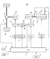
- FIG. 1 is a schematic configuration diagram showing an example in which the control device according to the first embodiment of the present invention is applied to a series hybrid vehicle.
- the hybrid vehicle 100 includes an internal combustion engine (engine 13) as a drive source.
- the hybrid vehicle 100 is provided with a navigation device 11 for acquiring the current position of the hybrid vehicle 100.
- the navigation device 11 receives GPS signals transmitted by a plurality of GPS (Global Positioning System) satellites above the hybrid vehicle 100 on satellite radio waves, positions the current position of the hybrid vehicle 100, and determines the current position of the hybrid vehicle 100.
- the current position is displayed on the map displayed on the display device.
- a base station of a mobile phone terminal, a Wi-Fi (registered trademark) access point, or the like may also be used for positioning the current position by the navigation device 11.
- the information on the current position of the hybrid vehicle 100 positioned by the navigation device 11 and the map information including the route to the surrounding area and the destination where the hybrid vehicle 100 travels are output to the vehicle control device, that is, VCU (Vehicle Control Unit) 1.
- VCU Vehicle Control Unit
- An accelerator opening sensor 6 and a brake switch 7 are provided in the cabin of the hybrid vehicle 100.
- the accelerator opening sensor 6 detects the amount of depression of the accelerator pedal, that is, the accelerator opening.
- the brake switch 7 detects whether or not the brake pedal is depressed.
- the engine 13 is a 4-cylinder gasoline engine for automobiles that uses spark-ignition combustion, and is an example of an internal combustion engine.
- the engine 13 includes a starter 12 for starting the engine 13.
- the crankshaft of the engine 13 is provided with a crank angle sensor 9b for detecting the rotation angle thereof, and the other end of the crankshaft is connected to the generator 14. Further, the engine 13 is provided with a cooling water temperature sensor 9c.
- the cooling water temperature sensor 9c measures the cooling water (coolant) that cools the engine 13.
- the internal combustion engine (engine 13) drives a generator (generator 14) to charge the electric power generated by the battery (battery 16). Therefore, the generator control device, that is, the GCU (Generator Control Unit) 3, controls the drive of the generator 14 via the inverter 15 so that the inverter 15 can charge the battery 16 at a predetermined voltage.
- the generator 14 is an example of a generator that is driven by an engine 13 to generate electricity and charges a battery 16 via an inverter 15.
- the battery control device that is, the BCU (Battery Control Unit) 4, controls the charging and discharging of the battery 16 based on the battery required output from the VCU 1.
- the battery 16 is provided with a battery voltage sensor 9a that measures the internal voltage of the battery 16, the VCU1 constantly checks the voltage of the battery 16, and information indicating the voltage of the battery 16 to the ECU 2 (for example, SOC). (State of Charge: charge rate)) is output.
- the motor control device controls the inverter 17 and the motor 18 based on the motor request output from the VCU 1. Power is supplied to the inverter 17 from the electrically connected battery 16. Then, the inverter 17 converts the DC power discharged from the battery 16 into AC power, and supplies the AC power to the motor 18.
- the motor 18 is connected to the wheels 20 via a reduction gear 19. Further, the drive shaft of the wheel 20 is provided with an automobile speed sensor 8.
- Each signal output from the automobile speed sensor 8, the battery voltage sensor 9a, the crank angle sensor 9b, and the cooling water temperature sensor 9c is sent to the VCU1.
- each signal output from the accelerator opening sensor 6 and the brake switch 7 is also sent to the VCU 1.
- the VCU 1 is mounted on an automobile (hybrid automobile 100) that travels by the output of at least one of an internal combustion engine (engine 13) and an electric drive unit (motor 18).
- the VCU 1 calculates the required torque of the driver based on the output signal of the accelerator opening sensor 6. That is, the accelerator opening sensor 6 is used as a required torque detection sensor that detects the required torque for the engine 13 and the motor 18. Further, the VCU 1 determines whether or not there is a driver's deceleration request based on the output signal of the brake switch 7. Further, the VCU 1 calculates the remaining battery level of the battery 16 based on the output signal of the battery voltage sensor 9a.
- the VCU 1 calculates the rotation speed of the engine 13 based on the output signal of the crank angle sensor 9b. Further, the VCU 1 calculates the temperature of the cooling water based on the output signal of the cooling water temperature sensor 9c. Then, the VCU 1 calculates the optimum operating amount of each device such as the engine required output, the motor required output, and the battery required output based on the driver request obtained from the outputs of the various sensors and the operating state of the hybrid vehicle 100.
- the engine request output calculated by VCU1 is sent to the engine control device, that is, the ECU 2. Further, the value of the internal voltage detected by the battery voltage sensor 9a is converted into the value of SOC indicating the remaining battery level of the battery 16 by the VCU 1 and then sent to the ECU 2.
- the internal combustion engine control device controls the output (operating point) of the internal combustion engine (engine 13) based on the required output from the VCU 1. Specifically, the ECU 2 controls the starter 12 in addition to the fuel injection unit, the ignition unit, and the throttle valve. Further, the motor request output calculated by VCU1 is sent to MCU5. Further, the battery request output calculated by VCU1 is sent to BCU4.
- FIG. 2 is a block diagram showing a hardware configuration example of VCU1.
- Each output signal output from the accelerator opening sensor 6, the brake switch 7, the vehicle speed sensor 8, the battery voltage sensor 9a, the crank angle sensor 9b, and the cooling water temperature sensor 9c is input to the input circuit 1a of the VCU1.
- the input signal is not limited to these.
- the input signal of each sensor input to the input circuit 1a is sent to an input port (not shown) in the input / output port 1b.
- the value sent to the input port is stored in the RAM 1c and is processed by the CPU 1e.
- the control program that describes the contents of the arithmetic processing performed by the CPU 1e is written in advance in the ROM 1d, and the CPU 1e reads the control program from the ROM 1d and executes it according to the processing.
- a value indicating the operating amount of the control target (engine 13, generator 14, battery 16, motor 18, etc.) calculated according to the control program is stored in the RAM 1c and then stored in the output port (not shown) in the input / output port 1b. It is sent and sent to each device via each output unit.
- the output unit there are an engine control output unit 1f, a motor control output unit 1g, a battery control output unit 1h, and a generator control output unit 1i.
- the circuits of each of these output units are connected to the ECU 2, the MCU 5, the BCU 4, and the GCU 3.
- control devices ECU2, MCU5, BCU4 and GCU3 to be controlled are separately provided for VCU1, but the present invention is not limited to this form, and the functional unit corresponding to the control device of each device is VCU1. You may prepare inside.
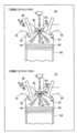
- the spark plug 40 is attached with the sub-chamber forming member 45 forming the sub-chamber 42, and the spark plug 40 integrated with the sub-chamber forming member 45 is attached to the engine 13. .
- the present invention is not limited to this configuration, and the sub chamber forming member 45 forming the sub chamber 42 may be attached to the engine 13, and the spark plug 40 may be attached to the sub chamber forming member 45. .. In any of these cases, FIG. 3 will be described.
- FIG. 3 is a diagram showing an installation example of the ignition device 50 and the sub chamber according to the first embodiment. First, a configuration example of the spark plug 40 in which the pressure sensor 46 is not attached to the sub chamber 42, which is shown in the upper explanatory view (1) of FIG. 3, will be described.
- the internal combustion engine (engine 13) has a main combustion chamber (main chamber 37) facing the piston (piston 35), a sub-combustion chamber (sub-chamber 42) communicating with the main combustion chamber (main chamber 37), and a sub-combustion chamber.
- An ignition plug (spark plug 40) attached to the inside of the (sub chamber 42) is provided.
- the fuel injected by the fuel injection device (fuel injection device 36) and the air taken in from the intake system (intake manifold 31) are mixed.
- the air-fuel mixture burns.
- the sub-combustion chamber (sub-chamber 42) takes in the air-fuel mixture from the main combustion chamber (main chamber 37).
- the ignition device 50 that applies a high voltage to the spark plug 40 is installed in the immediate vicinity of the spark plug 40.
- the intake manifold 31 is provided with a fuel injection device 36.
- the fuel injection device 36 injects fuel in accordance with a fuel injection command output by the ECU 2.
- the air-fuel mixture in which the air taken in from the intake manifold 31 and the fuel injected from the fuel injection device 36 are mixed is supplied to the main chamber 37. This air-fuel mixture is introduced into the main chamber 37 from the moment the piston 35 provided in the cylinder 38 of the engine 13 is lowered and the intake valve 32 is opened.
- the sub room 42 is installed in the main room 37.
- a plurality of communication passages 43 formed at the tip of the sub chamber 42 communicate the sub chamber 42 and the main chamber 37, and the air-fuel mixture that has passed through the communication passage 43 as the piston 35 rises in the compression step is subordinate. It is taken into the chamber 42.
- the intake valve 32 is closed, and the air-fuel mixture compressed in the process of ascending the piston 35 ignites in the vicinity immediately before the compression top dead center.
- the ignition of the air-fuel mixture is performed by the spark discharge generated in the electrodes 41 (ground electrode and center electrode) in the auxiliary chamber 42 by the ignition device 50 applying a high voltage to the spark plug 40.
- the flame generated in the sub chamber 42 due to the spark discharge passes through the communication passage 43 and is ejected into the main chamber 37 as a plurality of flame jets 44, and ignites the air-fuel mixture in the main chamber 37 at multiple points.
- the air-fuel mixture burned by the flame jet 44 rapidly expands and pushes down the piston 35 to generate engine torque. After that, the piston 35 rises, and the exhaust gas is discharged to the exhaust pipe 33 from the moment the exhaust valve 34 is opened.
- the pressure sensor 46 can detect the pressure in the sub chamber 42 (abbreviated as "sub chamber pressure").
- the data of the sub-chamber pressure detected by the pressure sensor 46 is input to the estimation unit 21 of the ECU 2 as the detection information shown in FIG. 4 to be described later.
- the operation of the ECU 2 using the spark plug 40A in which the pressure sensor 46 is attached to the sub chamber 42 will be described in the fifth embodiment described later.
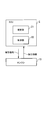
- FIG. 4 is a diagram showing a configuration example of a functional block of the ECU 2.
- the ECU 2 includes an estimation unit 21 and a control unit 22.
- the estimation unit 21 acquires the detection information detected by various sensors provided in the engine 13 and estimates the wall temperature of the sub-combustion chamber (sub-chamber 42) (hereinafter, referred to as “sub-chamber temperature”).
- the estimation unit (estimation unit 21) according to the present embodiment can estimate the sub-chamber temperature based on the cooling water temperature of the internal combustion engine (engine 13).
- control unit 22 controls the lower the sub-chamber temperature estimated by the estimation unit (estimation unit 21), the higher the sub-combustion chamber pressure (sub-chamber pressure) near the ignition timing of the internal combustion engine (engine 13).
- the internal combustion engine (engine 13) is controlled so as to be higher.
- the control unit (control unit 22) controls the generator (generator 14) so that the lower the sub-chamber temperature, the larger the internal combustion engine torque (engine torque). Therefore, the control unit 22 outputs a control signal to the engine 13.
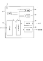
- FIG. 5 is a block diagram showing a hardware configuration example of the ECU 2.
- the output control signal output from the engine control output unit 1f (see FIG. 2) of the VCU 1 is input to the input circuit 2a of the ECU 2. Further, the output control signal input to the input circuit 2a is sent to an input port (not shown) in the input / output port 2b. The value sent to the input port is stored in the RAM 2c and arithmetically processed by the CPU 2e.
- the control program that describes the content of the arithmetic processing performed by the CPU 2e is written in advance in the ROM 2d, and the CPU 2e reads the control program from the ROM 2d and executes it according to the processing. Further, the detection information including the detection value detected by each sensor is input to the estimation unit 21.
- the detection information (SOC of the battery 16 and the like) output from the VCU 1 is also input to the estimation unit 21.
- the data of the sub-chamber temperature estimated by the estimation unit 21 based on the detection information is stored in the RAM 2c in chronological order for each cylinder 38 of the engine 13.
- Both the estimation unit 21 and the control unit 22 are arithmetically processed by the CPU 2e, and each function is realized.
- the ECU 2 also has various other functional units that control the operation of the engine 13 based on the control amount detected by each sensor provided in the engine 13, but the other functional units are not shown here. do.
- the value indicating the operating amount of the controlled object (ignition device 50, etc.) calculated according to the control program is stored in the RAM 2c, then sent to the output port (not shown) in the input / output port 2b, and passed through the control unit 22. It is sent to the controlled object.
- the control unit 22 outputs an ignition control signal (an example of a control signal) to the ignition device 50, and controls the operating point of the engine 13.
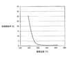
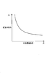
- FIG. 6 is a diagram showing the relationship between the sub-chamber temperature and the combustion volatility.
- the horizontal axis of the graph shown in FIG. 6 represents the sub-chamber temperature [° C.], and the vertical axis represents the combustion volatility [%].
- the combustion volatility is high when the sub-chamber temperature is low, such as when the engine 13 is started.
- the combustion volatility decreases as the temperature of the sub-chamber rises, that is, the combustion stabilizes. That is, if the temperature of the sub-chamber is low, the combustion fluctuation is not stable, and some measures are required to suppress the combustion fluctuation.
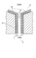
- FIG. 7 is an explanatory diagram of a flame extinguishing phenomenon in the communication passage 43 between the sub chamber 42 and the main chamber 37.
- the upper part of FIG. 7 is called the sub-chamber side where the sub-chamber 42 is provided, and the lower part of FIG. 7 is called the main room side where the main room 37 is provided.
- the air-fuel mixture is ignited by the spark plug 40 in the sub chamber 42, the flame propagates in the sub chamber 42, and the flame jets into the main chamber 37.
- the ejected flame starts combustion in the main chamber 37. That is, if the flame from the sub chamber 42 is not satisfactorily ejected into the main chamber 37, the combustion in the main chamber 37 becomes unstable and the flame may be extinguished.
- the distance between the flame generated in the sub chamber 42 and the wall surface of the sub chamber 42 becomes short, and the flame extinguishing phenomenon is likely to occur.
- the closest distance between the flame and the wall surface is in the connecting passage 43 connecting the main chamber 37 and the sub chamber 42.
- the flame propagating in the sub chamber 42 loses heat to the wall surface in the connecting passage 43, so that the flame cannot be maintained and is extinguished. This phenomenon is the main cause of combustion fluctuation when the engine 13 is started.
- premixed fuel and air and is quenching distance d e of the premixed flame occurs is ignited (the distance to the wall surface and the flame extinguishing can occur) is known to be expressed by the following formula (1) There is.
- the wall temperature (sub-chamber temperature) of the sub-chamber 42 has a great influence on the flame temperature T b.
- flame temperature T b in the communication passage 43 is significantly reduced, quenching distance d e increases.
- the quenching distance d e exceeds the diameter of the communication passage 43, the flame generated by the auxiliary chamber 42 will be anti-inflammatory.
- a region apart from the wall surface by quenching distance d e is shown as quenching region 80.
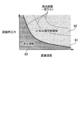
- FIG. 8 is a diagram showing the relationship between the sub-chamber temperature and the sub-chamber pressure.
- the horizontal axis of the graph shown in FIG. 8 represents the sub-chamber temperature, and the vertical axis represents the sub-chamber pressure.
- the relationship between the sub-chamber temperature and the sub-chamber pressure is shown by the solid line 81. Further, the relationship between the sub-chamber temperature at which the flame-extinguishing distance is constant and the sub-chamber pressure is represented by a broken line with a constant flame-extinguishing distance.
- the upper side of the solid line 81 represents the flame propagating region 82, and the lower side of the solid line 81 represents the flame extinguishing region 83.
- the solid line 81 that separates the flame propagating region 82 and the flame extinguishing region 83 is determined by the diameter of the communication passage 43 (also referred to as “communication passage diameter”).
- the flame generated in the sub-chamber 42 passes through the communication passage 43 and reaches the main chamber 37, and the air-fuel mixture in the main chamber 37 is exhausted. Ignite. However, if the relationship between the sub-chamber temperature and the sub-chamber pressure is in the flame-extinguishing region 83, the flame generated in the sub-chamber 42 is extinguished while passing through the communication passage 43, and the air-fuel mixture in the main chamber 37 cannot be ignited. ..
- the ECU 2 controls the sub-chamber pressure as shown by the solid line 81 based on the sub-chamber temperature. For example, the ECU 2 controls the engine 13 so that the lower the sub-chamber temperature, the higher the sub-chamber pressure so that the flame extinguishing distance becomes less than a certain value. By this control, it becomes possible to suppress the extinguishing of flames in the communication passage 43 and realize the stabilization of combustion.
- the engine operating point represents an engine speed and an engine torque set when the ECU 2 operates the engine 13.
- the engine operating point may be read as the power generation point when the inverter 15 is driven to generate electricity and the battery 16 is charged.
- FIG. 9 is a diagram showing an engine operating point based on the sub-chamber temperature.
- the horizontal axis of the graph shown in FIG. 9 represents the engine speed, and the vertical axis represents the engine torque.
- the ECU 2 controls so that the engine speed is reduced by the amount of the increased engine torque and the engine output is kept constant.
- the relationship between the engine speed and the engine torque in this control is represented by an equal output line shown by a broken line in FIG.
- the control unit 22 of the ECU 2 controls the engine operating point (power generation point) as follows.
- the control unit 22 sets the engine operating point to the point A when the engine torque is increased.
- the control unit 22 lowers the engine torque and shifts to the normal point B where the engine speed is increased as the temperature of the sub-chamber rises. In this way, the control unit 22 can keep the engine output constant by controlling the engine operating point to shift from the point A to the point B along the equal output line.
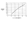
- FIG. 10 is a diagram showing the relationship between the engine cooling water temperature and the sub-chamber temperature.
- the horizontal axis of the graph shown in FIG. 10 represents the engine cooling water temperature, and the vertical axis represents the sub-chamber temperature.
- the method of estimating the sub-chamber temperature performed by the estimation unit 21 according to the embodiment of this embodiment will be described with reference to this figure.
- the graph shown in FIG. 10 is a plot of the engine cooling water temperature and the sub-chamber temperature for the period from immediately after the engine 13 is started (refrigerated) to when the engine 13 is warmed up.
- the sub-chamber temperature has a strong correlation with the cooling water temperature. Therefore, the estimation unit 21 of the ECU 2 estimates the sub-chamber temperature from the cooling water temperature measured by the cooling water temperature sensor 9c and calculated by the VCU 1 using the correlation shown in FIG. Then, the control unit 22 increases the engine torque so that the relationship between the sub-chamber temperature estimated by the estimation unit 21 and the sub-chamber pressure obtained from the sub-chamber temperature from FIG. 8 does not fall on the flame-extinguishing region 83 shown in FIG. And control the engine speed.
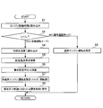
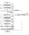
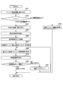
- FIG. 11 is a flowchart showing an example of a method of controlling the pressure in the sub-chamber.
- the control unit 22 of the ECU 2 reads the engine drive time, which is the elapsed time from the start of the engine 13, from the RAM 2c (S1). Next, the control unit 22 determines whether the engine driving time t e is less than the predetermined value t th, that is, whether engine 13 is or transient state immediately after starting (S2). If passed since sufficient time after the start of the engine 13 (NO in S2), i.e., if the engine driving time t e is a predetermined value t th or more, the controller 22 determines that a steady state. Then, the control unit 22 sets the normal engine operation point (point B) as the normal operation mode (S3), and ends the control related to this process.
- point B normal engine operation point
- the estimation unit 21 reads the cooling water temperature T c from the RAM 2 c (S4). Next, the estimation unit 21 performs a calculation for estimating the sub-chamber temperature based on the relationship between the engine cooling water temperature and the sub-chamber temperature shown in FIG. 10 based on the cooling water temperature T c (S5).
- the estimation unit 21 requests the engine 13 for the sub-chamber pressure (“Required sub-chamber pressure” based on the relationship between the sub-chamber temperature and the sub-chamber pressure shown in FIG. 8 based on the sub-chamber temperature estimated in step S5. ”) Is calculated (S6). Then, the control unit 22 sets the engine operating point (point A) at the time of cooling based on the relationship between the engine speed and the engine torque shown in FIG. 9 (S7).
- control unit 22 executes intake pressure control (throttle opening control) for realizing the engine operating point (point A) set in step S7 (S8), and performs a series of controls related to this process. finish.
- intake pressure control throttle opening control
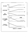
- FIG. 12 is a time chart showing an example of a method of controlling the pressure in the sub-chamber.
- the time chart shown in FIG. 12 shows the control shown in FIG. 11 regarding the cooling water temperature, the estimated sub-chamber temperature, the required sub-chamber pressure, the engine torque / engine rotation speed set value, and the intake pressure (throttle opening) in this order from the top.
- the time change after the start of the engine 13 according to the method is shown.
- the cooling water temperature and the estimated sub-chamber temperature are low.
- the cooling water temperature rises, and the sub-chamber temperature estimated by the estimation unit 21 from the cooling water temperature also rises.
- the required sub-chamber pressure required to prevent flame extinguishing decreases. Further, as the required sub-chamber pressure decreases, the set value of the engine torque decreases.
- the control unit 22 raises the set value of the engine speed as the engine torque decreases in order to keep the engine output (power generation amount) constant. Therefore, the control unit 22 controls so that the intake pressure (throttle opening degree) becomes low in order to realize the set engine torque and engine speed. Therefore, the control unit (control unit 22) reduces the pressure inside the cylinder (pressure inside the cylinder 38) of the internal combustion engine (engine 13) when the temperature of the sub-chamber becomes equal to or higher than the set temperature. Control the engine 13).
- the estimation unit 21 estimates the sub-chamber temperature based on the engine cooling water temperature, and determines the sub-chamber pressure based on the relationship between the sub-chamber temperature and the sub-chamber pressure.
- the control unit 22 controls the engine 13 at an operating point where a large engine torque is set at a low engine speed so that the sub-chamber pressure becomes large when the engine 13 is started (when the engine is cold).
- the control unit 22 controls the engine 13 at an operating point where a small engine torque is set at a high engine speed.
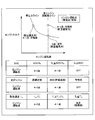
- FIG. 13 is a diagram showing an example of an engine operating point according to the second embodiment.
- the ECU 2 according to the second embodiment has two different operating points (A-1) depending on the condition of the hybrid vehicle 100 itself, the environmental condition of the hybrid vehicle 100, and the like when the sub-chamber temperature is low.
- the feature is to set points (points, A-2 points).
- Both points A-1 and A-2 represent operating points in which the engine torque is set to be larger than that in normal operation (point B) in a state where the sub-chamber temperature is high. Therefore, when the engine is cold, the control unit 22 maintains the engine speed and engine torque at points A-1 and A-2 to increase the pressure in the sub-chamber and suppress the extinguishing of flames in the sub-chamber 42. Is.
- point A-1 represents an operating point that has the same engine output (same amount of power generation) as the normal operating point (point B).
- the control unit 22 can drive the engine 13 while maintaining an appropriate remaining battery level of the battery 16 by utilizing point A-1 under conditions where the demand for power generation is not high, for example, for heating operation. It is possible.
- Point A-2 is an operating point where the engine output (power generation amount) is larger than that during normal operation (point B) indicated by point B. Points A-2 and B are both above the engine speed line (on the alternate long and short dash line) where the engine speeds are the same.
- the control unit 22 drives the engine 13 while maintaining an appropriate remaining battery level of the battery 16 by utilizing point A-2 under conditions where the demand for power generation is high, for example, when driving on a highway. Is possible. More specifically, as shown in the table below FIG. 13, depending on the remaining battery level of the battery 16, the driving scene, and the temperature range of the sub-chamber, the control unit 22 may perform points A-1, A-2, or B. Switch to one of the operating points. An example of three types of control will be described below with reference to the table at the bottom of FIG.
- control unit 22 changes the engine operating point based on the charge rate (SOC) of the battery 16 represented by the remaining battery level (Ah) / full charge capacity (Ah) ⁇ 100 will be described.
- the control unit 22 can receive the SOC of the battery 16 from the VCU 1.
- the control unit (control unit 22) has a lower internal combustion engine speed (engine rotation) as the sub-chamber temperature is lower and the charge rate (SOC) of the battery (battery 16) charged by the generator (generator 14) is lower.
- the internal combustion engine (engine 13) is controlled so that the number) becomes large.
- the charge rate (SOC) of the battery (battery 16) charged by the generator (generator 14) is the first set charge rate (first set SOC: lower limit value SL ). If it is less than, the internal combustion engine (engine 13) is controlled so that the internal combustion engine rotation speed (engine rotation speed) becomes the second set rotation speed (engine rotation speed at point A-2) to promote power generation. .. Then, when the sub-chamber temperature becomes equal to or higher than the set temperature (normal time), the control unit (control unit 22) sets the internal combustion engine rotation speed (engine rotation speed) to substantially the second set rotation speed (point A-2). The internal combustion engine (engine 13) is controlled so as to reduce the internal combustion engine torque (engine torque) and shift to the normal operating point (point B) while maintaining the engine speed).
- the charge rate (SOC) of the battery (battery 16) charged by the generator (generator 14) is equal to or higher than the first set charge rate (first set SOC: lower limit value SL).
- first set SOC lower limit value SL
- the internal combustion engine (engine 13) is controlled so that the internal combustion engine speed (engine speed) becomes the first set speed (engine speed at point A-1). That is, if the charging rate (SOC) is less than the lower limit value S L or more and the upper limit value S H, the control unit 22 sets the A-1 point, keeping the charging rate (SOC) in a predetermined range.
- control unit 22 sets the internal combustion engine rotation speed (engine rotation speed) to the first set rotation speed (engine at point A-1).
- the control unit sets the internal combustion engine rotation speed (engine rotation speed) to the first set rotation speed (engine at point A-1).
- the second set speed (engine speed at point B) higher than the speed) and lowering the internal combustion engine torque (engine torque) becomes almost constant.
- the internal combustion engine (engine 13) is controlled in this way.
- the control unit 22 stops the engine 13 and sets the amount of power generation to 0 (the engine operating point is described as OFF in the figure). That is, in the control unit (control unit 22), the charge rate (SOC) is higher than the first set charge rate (first set SOC: lower limit value SL ), and the second set charge rate (second set SOC: upper limit value S). When it becomes H) or more, the operation of the internal combustion engine (engine 13) is controlled to be stopped.
- control unit 22 when a vehicle (hybrid vehicle 100) equipped with an internal combustion engine (engine 13) is traveling on a highway, the vehicle (hybrid vehicle 100) travels on a general road (suburb).
- the internal combustion engine (engine 13) is controlled so that the internal combustion engine rotation speed (engine rotation speed) is higher than that in the case of being inside.
- the control unit 22 sets the driving point to the A-2 point and increases the amount of power generation while the hybrid vehicle 100 is traveling on the highway.
- the control unit 22 sets the A-1 point as the driving point.
- the remaining battery level of the battery 16 is kept within a certain range.
- the control unit 22 stops the engine 13 and sets the amount of power generation to 0 (the engine operating point is described as OFF in the figure).
- the control unit 22 sets the A-2 point and operates with high output to raise the sub-chamber temperature at an early stage.
- the control unit 22 sets the A-1 point, while maintaining the combustion stability, controlled so as to maintain the SOC within a predetermined range do.
- the sub-room temperature of T pc is greater than or equal to the upper value T H, since after being sufficiently warm, control unit 22 sets the point B during normal operation.
- the control unit 22 switches the driving point based on the vehicle state (battery remaining amount, sub-chamber temperature) and the driving scene of the hybrid vehicle 100 estimated by the estimation unit 21. I do.
- the vehicle state battery remaining amount, sub-chamber temperature
- the driving scene of the hybrid vehicle 100 estimated by the estimation unit 21. I do.
- the ECU 2 according to the present embodiment has an effective diameter of a communication passage 43 in an engine 13 having a fuel injection device 36 provided in an intake manifold 31 and a fuel injection device 36A provided in a sub chamber 42 as shown in FIG. It is characterized in that the pressure in the sub-chamber is controlled based on (hereinafter, referred to as "effective communication passage diameter").
- FIG. 14 is a diagram showing an installation example of the ignition device 50 and the sub chamber 42 according to the third embodiment.
- the spark plug 40B according to the third embodiment has a configuration in which the fuel injection device 36A is attached to the side surface of the auxiliary chamber forming member 45. That is, the internal combustion engine (engine 13) includes a second fuel injection device (fuel injection device 36A) that directly injects fuel into the sub-combustion chamber (sub-chamber 42).
- a flame ignited by a spark discharge generated at the electrode 41 with respect to the fuel injected by the fuel injection device 36A in the sub chamber 42 passes through a communication passage 43 formed in the sub chamber forming member 45 and a plurality of flame jets 44. Erupt as.
- the intake manifold 31 is also provided with the fuel injection device 36, as in the engine 13 according to the first embodiment.
- the fuel injected by the fuel injection device 36 fills the main chamber 37, and then is ignited at multiple points by the flame jet 44 ejected from the communication passage 43 of the sub chamber 42.
- the sub chamber 42 is provided with a pressure sensor 46 that measures the pressure in the sub chamber.
- the sub-chamber pressure is used by the estimation unit 21 to estimate the effective communication passage diameter, as will be described later with reference to FIG. Therefore, the estimation unit 21 included in the ECU 2 according to the third embodiment estimates the effective communication passage diameter of the communication passage 43 provided in the sub-combustion chamber (sub-chamber 42). Then, the control unit 22 controls the sub-chamber pressure based on the effective communication passage diameter estimated by the estimation unit 21. For example, the control unit (control unit 22) controls the second fuel injection device (fuel injection device 36A) not to perform fuel injection when the estimated effective communication passage diameter becomes equal to or less than a predetermined value.
- FIG. 15 is a diagram showing an example of an effective communication passage diameter D eff between the sub chamber 42 and the main chamber 37.
- the diameter of the communication passage 43 is optimally designed for each engine 13 so that stable and high-speed combustion can be realized in the main chamber 37.
- incomplete combustion products such as fuel and soot are deposited inside the communication passage 43.
- the incomplete product thus deposited inside the communication passage 43 is called a "combustion deposit”.
- the width between the combustion deposits 47 deposited on the surface of the communication passage 43 is called the effective communication passage diameter D eff. If no combustion deposit is generated in the communication passage 43, the diameter of the communication passage 43 becomes the effective communication passage diameter D eff as it is. However, when a combustion deposit occurs, the effective communication passage diameter D eff narrows.
- the flame jet 44 that passes through the communication passage 43 and ejects into the main chamber 37 also weakens or extinguishes the flame.
- the effective communication passage diameter D eff varies from individual to individual in the sub chamber 42 and changes in real time due to secular changes such as accumulation of combustion deposit 47 and individual differences in the sub chamber 42 due to manufacturing variations.
- the combustion deposit 47 is generated when the fuel adheres to the inside of the sub chamber 42 or the air and the fuel are incompletely mixed. Therefore, the combustion deposit 47 may be remarkably generated particularly in the engine 13 provided with the fuel injection device 36A in the sub chamber 42. Then, as the effective communication passage diameter D eff decreases, the frequency of extinguishing the flame jet 44 in the communication passage 43 increases. Therefore, it is necessary to control the pressure in the sub-chamber based on the effective communication passage diameter D eff.
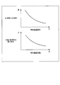
- FIG. 16 is a diagram showing the relationship between the effective communication passage diameter D eff , the main combustion center timing, and the maximum differential pressure between the main chamber 37 and the sub chamber 42.
- the estimation unit 21 can estimate the change in the effective communication passage diameter D eff from the main combustion center time in the main chamber 37 and the maximum differential pressure between the main chamber 37 and the sub chamber 42.
- FIG. 17 is a diagram showing the relationship between the effective communication passage diameter D eff and the sub-chamber pressure.
- Effective communication passage diameter D eff is below the quenching distance d e of the flame already described in the first embodiment (see FIG. 7), the anti-inflammatory for in the communication passage 43 occurs. Therefore, in order to avoid extinguishing the flame in the communication passage 43, the control unit 22 controls to increase the pressure in the sub-chamber as the effective communication passage diameter D eff decreases, and shortens the flame extinguishing distance. By such control, the ECU 2 can prevent the flame extinguishing in the communication passage 43.
- FIG. 18 is a flowchart showing an example of a method of controlling the pressure in the sub-chamber.
- the estimation unit 21 reads the cooling water temperature T c calculated by the VCU 1 based on the output signal of the cooling water temperature sensor 9c from the RAM 2c (S11). Then, the estimation unit 21 performs an operation of estimating the sub- chamber temperature T pc from the cooling water temperature T c based on the relationship between the cooling water temperature and the sub-chamber temperature shown in FIG. 10 (S12).
- the estimation unit 21 compares the estimated sub-chamber temperature T pc with the predetermined value T th, and determines whether or not the sub- chamber temperature T pc is less than the predetermined value T th (S13).
- the control unit 22 sets a normal engine operating point (for example, point B) (S14) and controls by this process. To finish.
- the estimation unit 21 determines that the sub chamber temperature T pc is less than the predetermined value T th (YES in S13), the value of the pressure sensor 46 installed in the sub chamber 42 (sub chamber pressure) is determined. Read from RAM 2c (S15). Then, the estimation unit 21 determines the maximum differential pressure between the internal pressure of the sub-combustion chamber (sub-chamber 42) and the internal pressure of the main combustion chamber (main chamber 37) and the main combustion center time based on the read sub-chamber pressure. , At least one is calculated (S16).
- the estimation unit 21 sets the maximum differential pressure calculated from the internal pressure of the sub-combustion chamber (sub-chamber 42) and the internal pressure of the main combustion chamber (main chamber 37) to at least one of the main combustion center period. Based on this, the effective communication passage diameter D eff is estimated using the relationship shown in FIG. 16 (S17).
- control unit 22 calculates the required sub-chamber pressure based on the estimated effective communication passage diameter D eff , using the relationship between the effective communication passage diameter and the sub-chamber pressure shown in FIG. 17 (S18). After that, the control unit 22 sets the engine operating point (engine torque, engine speed) at the time of cooling in order to realize the required sub-chamber pressure (S19).
- control unit 22 executes intake pressure control (throttle opening degree control) for realizing the engine operating point set in step S19 (S20). That is, in the control unit (control unit 22), when the sub- chamber temperature (sub-chamber temperature T pc) is less than the temperature set value (predetermined value T th ), the smaller the estimated effective communication passage diameter, the more the internal combustion engine (engine). The internal combustion engine (engine 13) is controlled so that the sub-combustion chamber pressure (sub-chamber pressure) near the ignition timing of 13) becomes high. After that, the control unit 22 ends a series of controls related to this process.
- intake pressure control throttle opening degree control
- the ECU 2 it is possible to control the pressure in the sub-chamber in response to a change in the effective communication passage diameter D eff. Therefore, the ECU 2 can prevent the flame extinguishing in the communication passage 43 during the cold operation of the engine 13.
- the ECU 2 according to the present embodiment controls the engine 13 based on the sub-chamber temperature estimated by using the primary current and the voltage signal energized in the ignition device 50.
- a configuration example of the ignition device 50 and a control method for suppressing the combustion volatility will be described below.
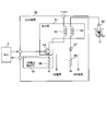
- FIG. 19 is a diagram showing a configuration example of the ignition device 50.
- the ignition device 50 includes an ignition unit 51, a primary current detection unit 55, a diode 57, and a resistor 58.
- the parts included in the ignition device 50 are collectively arranged in the plug cap of the ignition device 50 included in each cylinder 38.
- the ignition unit is primary to the primary coil (primary coil 52) to which the primary current is energized and to the primary coil (primary coil 52) when the ignition control signal is turned on. It is generated when the igniter (igniter 54) that energizes the current and cuts off the primary current when the ignition control signal is turned off and the igniter (igniter 54) that turns off the ignition control signal cuts off the primary current. It includes a secondary coil (secondary coil 53) that outputs a secondary current to an electrode (electrode 41).
- a voltage of + 12V is applied from the battery 16 to the primary coil 52, and a primary current flows through the primary coil 52.
- the primary coil 52 and the secondary coil 53 are examples of ignition coils that apply a high voltage current to the spark plug 40.
- the turns ratio of the secondary coil 53 to the primary coil 52 is, for example, 100 times.
- the primary current supplied from the battery 16 passes through the primary coil 52 of the ignition unit 51 and collects the igniter 54. Is output to the emitter.
- the emitter is grounded via a resistor 56 provided in the primary current detection unit 55.
- the primary current detection unit detects the primary current energized by the resistor 56
- the primary current detection unit outputs ignition device information including the value of the primary current to the ECU 2.
- one end of the secondary coil 53 is connected to the electrode 41 of the spark plug 40, and the other end of the secondary coil 53 is connected to the anode of the diode 57.
- the cathode of the diode 57 is grounded via a resistor 58.
- the primary current flowing through the igniter 54 is cut off.
- a magnetic field change is generated in the primary coil 52, and a primary voltage is generated by self-induction.
- a high secondary voltage corresponding to the turns ratio is generated in the secondary coil 53 that shares the magnetic circuit and the magnetic flux with the primary coil 52 by mutual induction.
- a secondary voltage is applied to the electrode 41 of the spark plug 40, and a spark discharge is generated at the electrode 41. Further, the secondary current generated by inducing the secondary voltage in the secondary coil 53 flows through the diode 57 and the resistor 58.
- FIG. 20 is a block diagram showing a functional configuration example of the ECU 2 and the ignition device 50.
- the ECU 2 includes an estimation unit 21 and a control unit 22.
- the estimation unit 21 estimates the temperature of the sub-combustion chamber (sub-chamber 42) based on the ignition device information output from the ignition device (ignition device 50) that ignites the spark plug (spark plug 40). ..
- This estimation unit (estimation unit 21) is a sub-combustion chamber (secondary combustion chamber) based on the time change of the primary current during the charging period in which the primary coil (primary coil 52) of the ignition unit 51 shown in FIG. 19 is charged with energy.
- the temperature of the chamber 42) can be estimated.
- the estimation unit (estimation unit 21) performs secondary combustion based on the change in the primary current detected by the primary current detection unit (primary current detection unit 55) when the ignition control signal is turned on or off.
- the temperature of the chamber (secondary chamber 42) is estimated.
- the ignition control unit (control unit 22) outputs an ignition control signal for switching on or off of the igniter (igniter 54) shown in FIG. 19 to the ignition device (ignition device 50).
- ignition control signal By this ignition control signal, the timing at which the igniter 54 energizes or shuts off the primary current is switched, and the timing at which the ignition unit 51 ignites the spark plug 40 is controlled. Then, when the primary current is cut off, the secondary coil 53 boosts the pressure, applies a high voltage to the electrode 41 of the spark plug 40, and spark discharge is generated from the electrode 41.
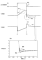
- FIG. 21 is a graph showing changes in the ignition control signal, the primary current, and the primary voltage. Here, it will be described with reference to the circuit diagram of the ignition device 50 shown in FIG.
- a graph of a current waveform obtained by detecting the primary current of the spark plug 40 by the primary current detection unit 55 and a voltage waveform of the primary voltage is shown.
- the change in the primary current when the sub-chamber temperature is low is represented by a solid line
- the change in the primary current when the sub-chamber temperature is high is represented by a broken line.
- the time change of the primary current and the primary voltage is determined by the estimation unit 21 that has received the ignition device information including the value of the primary current detected by the primary current detection unit 55.
- the coil resistance of the primary coil 52 is low, so that the primary current easily flows through the primary coil 52. Therefore, the time required from when the ignition control signal is turned on at time t11 until the energy of the primary current is charged to the primary coil 52 is short, and as shown as the region 61a in the figure, the primary current The slope is steep.
- FIG. 21 An enlarged view of the area 62a of FIG. 21 is shown on the lower side of FIG. 21. This enlarged view shows how the primary current changes over time when the sub-chamber temperature is low, medium, or high. From the lower side of FIG. 21, as the temperature of the sub-chamber rises, the amount of undershoot of the primary current increases, and it takes time for the value of the primary current to return to the same value as before the ignition control signal was turned on. You can see that.
- the estimation unit estimate unit 21
- the sub-combustion chamber sub-chamber
- the change in the primary voltage when the sub-chamber temperature is low is represented by a solid line
- the primary voltage when the sub-chamber temperature is high is shown.
- the change in is represented by a broken line.
- the primary current is applied to the primary coil 52. The primary voltage until the energy is charged changes in the same way.
- the estimation unit 21 can determine the sub-chamber temperature by converting the primary current detected by the primary current detection unit 55 into the primary voltage and obtaining the change in the primary voltage.
- the estimation unit estimate unit 21
- the ignition control signal is turned off and the primary voltage applied to the primary coil (primary coil 52) returns to the value before the ignition control signal is turned on. It is estimated that the longer the time, the higher the temperature of the sub-combustion chamber (sub-chamber 42).
- the control unit calculates the sub-chamber pressure according to the relationship shown in FIG. 8 based on the estimated sub-chamber temperature, and the control unit (control unit 22) subordinates according to the relationship shown in FIG.
- the engine torque and engine speed of the engine 13 are controlled according to the room temperature.
- the sub-chamber temperature is estimated based on the changes in the primary current and the primary voltage of the ignition device 50 obtained by the estimation unit 21 from the ignition device information. Then, the control unit 22 controls the engine 13 at a predetermined operating point according to the estimated sub-chamber temperature. Therefore, the ECU 2 can prevent the flame extinguishing during the cold operation of the engine 13 and suppress the combustion fluctuation.
- the ECU according to the fifth embodiment of the present invention will be described with reference to FIGS. 22 and 23.
- the configuration of the ECU according to this embodiment is the same as that of the first embodiment.
- the present embodiment is characterized in that the calculation unit detects the combustion volatility and the control unit performs feedback control of the intake pressure according to the combustion volatility.
- the estimation unit 21 according to the present embodiment represents the combustion fluctuation state of the engine 13 including the spark plug 40A in which the pressure sensor 46 is installed in the sub chamber 42 shown in the explanatory view (2) of FIG. A method of estimating the combustion volatility and controlling the engine 13 will be described.
- FIG. 22 is a flowchart showing an example of a method of controlling the pressure in the sub-chamber.
- steps S21 to S28 in FIG. 22 are the same as the processes of steps S1 to S8 according to the first embodiment, detailed description thereof will be omitted.
- the estimation unit 21 determines the combustion fluctuation based on the sub-chamber pressure detected by the pressure sensor 46 installed in the sub-chamber 42. An operation is performed to estimate the combustion fluctuation rate, which is an example of the state (S29). Next, the control unit 22 compares the calculated combustion volatility with a predetermined threshold value, and determines whether or not the combustion volatility is less than the threshold value (S30).
- the control unit 22 determines that the flame jet 44 has not extinguished the flame, and sets, for example, "0" to the flame extinguishing flag that secures the area in the RAM 2c. A series of controls related to this process is terminated.
- the control unit (control unit 22) extinguishes the flame jet 44 in the control unit 22. Judge that it is, and set "1" to the flame extinguishing flag. Then, the control unit (control unit 22) increases the set torque of the engine 13 (S31) so that the internal combustion engine torque (engine torque) becomes large, and is driven by the internal combustion engine (engine 13) to generate electric power. It controls a generator (generator 14) that charges a battery (battery 16). After that, the control unit 22 proceeds to control the intake pressure again (S28). The control of steps S28 to S31 is repeatedly executed until the combustion volatility becomes equal to or less than the threshold value.
- FIG. 23 is a time chart showing an example of a method of controlling the pressure in the sub-chamber.
- This time chart shows the combustion fluctuation rate, flame extinguishing flag, set engine torque (described as “torque” in the figure), set engine speed (described as “rotation speed” in the figure), and intake pressure (throttle opening). It shows a change over time.
- the combustion volatility is less than the threshold value indicated by the broken line, and the flame extinguishing flag is set to "0".
- the engine torque, engine speed, and intake pressure are all "0".
- the estimation unit 21 calculates the combustion volatility.
- the control unit 22 sets the flame extinguishing flag to “1”.
- the control unit 22 increases the set value of the engine torque and controls the intake pressure to be high (throttle opening degree is large) so that the engine torque is increased.
- the combustion volatility is lowered and the engine speed is also lowered.
- the control unit 22 sets the flame extinguishing flag to “0”. Then, the control unit 22 constantly controls the engine torque set value and the intake pressure.
- the control unit 22 determines the flame extinguishing based on the combustion volatility estimated in real time by the estimation unit 21, and controls the sub-chamber pressure. Therefore, the ECU 2 can execute robust combustion stability control against variations in parts of the engine 13 and changes in the environment.
- the estimation unit 21 according to the fifth embodiment can also estimate the combustion fluctuation rate based on the fluctuation of the rotation angle of the crankshaft detected by the crank angle sensor 9b.
- FIGS. 24 to 26 A feature of the present embodiment is that the present invention is applied not to a hybrid vehicle but to a gasoline vehicle driven by the driving force of only the engine 13. Further, the ECU 2 is characterized in that by controlling the effective compression ratio of the engine 13, the sub-chamber pressure is suitably controlled without changing the engine torque and the engine speed.
- FIG. 24 is a schematic configuration diagram showing an example in which the control device according to the present embodiment is applied to the gasoline engine vehicle 100A.
- the gasoline engine vehicle 100A shown in FIG. 24 does not include a motor 18, inverters 15, 17, a battery 16, and a generator 14, and drives only the engine 13. Used for.
- the engine 13 is provided with a compression ratio variable mechanism 101 capable of changing the effective compression ratio.
- a catalyst temperature sensor 9d for detecting the temperature of the three-way catalyst provided for the engine 13 is provided. Information indicating the temperature of the three-way catalyst detected by the catalyst temperature sensor 9d is stored in the RAM 2c of the ECU 2.
- This gasoline engine vehicle 100A does not use VCU1 (see FIG. 1) as a control device, but uses only ECU 2 as a control device to control the engine 13.
- the internal combustion engine (engine 13) is used to drive an automobile (gasoline engine automobile 100A) including the internal combustion engine (engine 13).
- FIG. 25 is a flowchart showing an example of a method of controlling the pressure in the sub-chamber.
- the control unit 22 of the ECU 2 reads the engine drive time, which is the elapsed time from the start of the engine 13, from the RAM 2c (S41). Next, the control unit 22, whether the engine driving time t e is less than the predetermined value t th, i.e. determines whether a transient state immediately after starting the engine 13 (S42).
- Engine driving time t e is a predetermined value t th or more, if passed since sufficient time after the start of the engine 13 (NO in S42), the control unit 22 determines that the steady state. Then, the control unit 22 sets the normal opening time of the intake valve 32 (hereinafter, referred to as “intake valve opening time”) as the normal operation mode (S43), and ends the control related to this process.
- intake valve opening time the normal opening time of the intake valve 32
- the estimation unit 21 first reads the cooling water temperature T c calculated by the VCU 1 based on the output signal of the cooling water temperature sensor 9c from the RAM 2c (S44). Next, the estimation unit 21 performs an operation of estimating the sub-chamber temperature based on the cooling water temperature T c and the relationship shown in FIG. 10 (S45).
- the estimation unit 21 calculates the required sub-chamber pressure based on the relationship between the sub-chamber temperature and the sub-chamber pressure shown in FIG. 8 based on the sub-chamber temperature estimated in step S45 (S46). Then, the control unit 22 calculates the required effective compression ratio required to realize the required sub-chamber pressure (S47). More specifically, the required effective compression ratio is obtained by the adiabatic compression formula based on the intake pressure and the required sub-chamber pressure.
- control unit 22 sets the closing timing of the intake valve 32 (hereinafter, referred to as “intake valve closing timing”) for realizing the required effective compression ratio (S48). That is, in step S48, the control unit (control unit 22) sets the intake valve closing timing and the compression ratio variable mechanism (compression ratio) so that the lower the sub-chamber temperature, the higher the effective compression ratio of the internal combustion engine (engine 13). At least one of the variable mechanisms 101) is controlled. Then, the control unit 22 ends a series of controls related to this process.
- FIG. 26 is a time chart showing an example of a method of controlling the pressure in the sub-chamber.
- the time chart shown in FIG. 26 shows the time changes from the start of the engine 13 with respect to the cooling water temperature, the estimated sub-chamber temperature, the required sub-chamber pressure, the required effective compression ratio, and the intake valve closing timing in order from the top. ..
- the cooling water temperature and the estimated sub-chamber temperature are low.
- the cooling water temperature rises, and the sub-chamber temperature estimated by the estimation unit 21 from the cooling water temperature also rises.
- control unit 22 controls the intake valve 32 so that the intake valve closing timing is delayed from the BDC (Bottom Dead Center) side to the TDC (Top Dead Center) side.
- the required sub-chamber pressure is calculated based on the sub-chamber temperature estimated by the estimation unit 21 even in the gasoline engine vehicle 100A in which the engine torque and the rotation speed cannot be freely set.
- the control unit 22 controls the intake valve closing timing for realizing the required effective compression ratio of the engine 13. By this control, the control unit 22 can set the optimum sub-chamber pressure without changing the engine torque and the engine speed of the engine 13, so that it is possible to avoid the combustion instability when the engine 13 is cooled. It will be possible.
- the engine control method according to the seventh embodiment of the present invention will be described with reference to FIGS. 27 and 28. Similar to the sixth embodiment, the present embodiment is also characterized in that the present invention is applied not to the hybrid vehicle 100 but to the gasoline engine vehicle 100A driven by the driving force of only the engine 13. This embodiment shows an example in which the present control is applied particularly to the catalyst warm-up operation for activating the three-way catalyst provided in the exhaust pipe 33 of the engine 13. The control method of the engine 13 according to the seventh embodiment will be described below.
- FIG. 27 is a flowchart showing an example of a method of controlling the pressure in the sub-chamber.
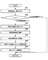
- the control unit 22 of the ECU2 reads the catalyst temperature t cat of the three-way catalyst from RAM 2c (S51). Next, it is determined whether or not the catalyst temperature tcat is equal to or lower than a predetermined value, that is, whether or not it is a transition state immediately after the engine 13 is started (S52).
- control unit 22 determines that the catalyst temperature tcat is equal to or higher than the threshold value (NO in S52), that is, the three-way catalyst is activated, the control unit 22 terminates the control in the normal operation mode. On the other hand, when the control unit 22 determines that the catalyst temperature tcat is equal to or lower than the threshold value (YES in S52), that is, the three-way catalyst is not activated, the control unit 22 enters the catalyst warm-up mode.
- the estimation unit 21 reads the cooling water temperature T c from the RAM 2 c (S53). Next, based on the cooling water temperature Tc , the sub-chamber temperature is estimated from the relationship shown in FIG. 10 (S54).
- the required sub-chamber pressure is calculated based on the relationship between the sub-chamber temperature and the sub-chamber pressure shown in FIG. 8 based on the sub-chamber temperature estimated by the estimation unit 21 (S55).
- the intake pressure throttle opening degree
- S56 the required sub-chamber pressure
- the ECU 2 controls the retard amount (ignition retard control) to retard the ignition timing so as not to increase the engine torque even when the intake pressure increases (S57), and ends the control.
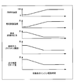
- FIG. 28 is a time chart showing an example of a method of controlling the pressure in the sub-chamber.
- the time chart shown in FIG. 28 shows, in order from the top, changes in cooling water temperature, estimated sub-chamber temperature, required sub-chamber pressure, intake pressure (throttle opening), and ignition timing retard amount after the start of the engine 13. Shown.
- control unit 22 controls the throttle valve so that the lower the temperature of the sub-chamber, the larger the throttle opening degree of the throttle valve provided in the internal combustion engine (engine 13).
- control unit 22 lowers the intake pressure as the required sub-chamber pressure drops. Further, the control unit 22 reduces the ignition timing retard amount so as to keep the engine torque constant. That is, the control unit (control unit 22) controls the ignition device (ignition device 50) that ignites the spark plug (ignition plug 40) so that the lower the temperature of the sub-chamber, the retarder the ignition timing.
- the control unit 22 controls the intake pressure and the ignition retard during the catalyst warm-up operation. Perform combined control. By these controls, the control unit 22 can maintain the exhaust temperature required for catalyst warm-up while avoiding combustion instability without changing the torque and the rotation speed of the engine 13.
- the fuel injection device (fuel injection device 36) is installed in at least one of an intake system (intake manifold 31), a main combustion chamber (main chamber 37), and a sub combustion chamber (sub chamber 42).
- intake system intake manifold 31
- main chamber 37 main combustion chamber
- sub chamber 42 sub combustion chamber
- a direct injection type fuel injection device 36 capable of directly injecting fuel may be adopted.
- a temperature sensor such as a thermoelectric pair may be installed in the wall of the sub chamber 42, and the ECU 2 may directly measure the sub chamber temperature based on the value detected by the temperature sensor. Then, the estimation unit (estimation unit 21) estimates the temperature of the sub-chamber based on the value detected by the temperature sensor attached to the sub-combustion chamber (sub-chamber 42). If the sub-chamber temperature can be directly measured in this way, the accuracy of the measured temperature can be improved, and the sub-chamber pressure can be controlled more appropriately.
- the estimation unit ignites the value detected by the temperature sensor attached to the sub-combustion chamber (sub-chamber 42), the cooling water temperature of the internal combustion engine (engine 13), and the spark plug (spark plug 40).
- the sub-chamber temperature may be estimated based on at least one of the ignition device information output from the ignition device (ignition device 50).
- a pressure sensor may be installed in at least one of the sub chamber 42 and the main chamber 37 in order to detect the combustion volatility.
- the combustion volatility may be estimated from the data of the crank angle sensor that measures the engine speed.
- each of the above-described embodiments describes in detail and concretely the configurations of the apparatus and the system in order to explain the present invention in an easy-to-understand manner, and is not necessarily limited to those including all the described configurations.
- it is possible to replace a part of the configuration of the embodiment described here with the configuration of another embodiment and further, it is possible to add the configuration of another embodiment to the configuration of one embodiment. It is possible. It is also possible to add, delete, or replace a part of the configuration of each embodiment with another configuration.
- the control lines and information lines indicate those that are considered necessary for explanation, and do not necessarily indicate all the control lines and information lines in the product. In practice, it can be considered that almost all configurations are interconnected.
Landscapes
- Engineering & Computer Science (AREA)
- Chemical & Material Sciences (AREA)
- Combustion & Propulsion (AREA)
- Mechanical Engineering (AREA)
- General Engineering & Computer Science (AREA)
- Signal Processing (AREA)
- Combined Controls Of Internal Combustion Engines (AREA)
- Control Of Vehicle Engines Or Engines For Specific Uses (AREA)
- Electrical Control Of Ignition Timing (AREA)
- Combustion Methods Of Internal-Combustion Engines (AREA)
- Control Of Throttle Valves Provided In The Intake System Or In The Exhaust System (AREA)
- Output Control And Ontrol Of Special Type Engine (AREA)
Abstract
副室を設けたエンジンでは、エンジン始動直後など副室温度が低い条件において、副室内で火炎の消炎現象が発生し、燃焼が不安定になりやすかった。 ピストンに面する主燃焼室と、主燃焼室に連通する副燃焼室と、副燃焼室の内部に取り付けられる点火プラグと、燃料噴射装置が噴射する燃料と、吸気系から吸気される空気とが混合された混合気が、主燃焼室及び副燃焼室で燃焼するシリンダと、を備えたエンジン13を制御するECU2は、副燃焼室の壁温度を推定する推定部21と、推定部21により推定された副燃焼室の壁温度が低いほど、エンジン13の点火時期近傍での副燃焼室内圧力が高くなるようにエンジン13を制御する制御部22と、を備える。
Description
本発明は、内燃機関制御装置に関する。
従来、自動車のエンジンに設けられる内燃機関用の点火装置(「点火コイル」とも呼ぶ)は、主として、1次電流を流す1次コイルと、1次コイルに生じた磁束変化が相互誘導される2次コイル、及び1次電流の通電及び遮断を制御するイグナイタとで構成されている。この点火装置は、点火制御装置(例えば、ECU:Engine Control Unit)から出力される点火制御信号がオンからオフに変わって、1次電流が遮断されると、2次コイルに発生した高電圧によって点火プラグに火花放電が発生し、混合気を着火する。
近年の燃費規制の施行に伴い、点火装置には、小型化及び高出力化が要求されている。
また、高電圧でも高い耐久性を有する点火装置が必要とされている。そこで、ピストンが往復運動することが可能であって、燃料が噴射されるシリンダ内の主燃焼室(「主室」と略記する)に対して、点火プラグにより燃料に点火して生じた火炎ジェットを主室に導くための副燃焼室(「副室」と略記する)を備えたエンジンが提供されつつある。
また、高電圧でも高い耐久性を有する点火装置が必要とされている。そこで、ピストンが往復運動することが可能であって、燃料が噴射されるシリンダ内の主燃焼室(「主室」と略記する)に対して、点火プラグにより燃料に点火して生じた火炎ジェットを主室に導くための副燃焼室(「副室」と略記する)を備えたエンジンが提供されつつある。
特許文献1には、「多気筒ガスエンジンの副室へ副室ガス供給電磁弁によって個別に燃料ガスを導入し、点火プラグで着火する副室式ガスエンジンの副室ガス供給制御装置において、副室内又は該副室近傍の温度を検出する副室内温度検出手段と、副室内温度を所定範囲内に維持すると共に、副室内部の空気過剰率が所定の値になるように、副室ガス供給電磁弁の開時間を制御する副室ガス供給制御手段とを備える。」と開示されている。
ところで、副室の容積は主室の容積より小さいため、副室を設けたエンジンにおいては、副室の内壁温度(「副室温度」と呼ぶ)が低い状況において、副室内の混合気に点火できなかったり、副室内で点火された火炎が消失したりするような消炎が発生しやすい。そして、エンジン始動直後など、副室が十分に暖気されていない場合に、エンジンの燃焼変動が大きくなってしまうという課題がある。また、特許文献1に記載された技術は、空燃比制御によって燃焼変動を抑制するため、排気や燃費の悪化が生じる恐れがあった。
本発明はこのような状況に鑑みて成されたものであり、燃費や排気を悪化させずに副燃焼室を有するエンジンの燃焼を安定化することを目的とする。
本発明に係る内燃機関制御装置は、ピストンに面する主燃焼室と、主燃焼室に連通する副燃焼室と、副燃焼室の内部に取り付けられる点火プラグと、燃料噴射装置が噴射する燃料と、吸気系から吸気される空気とが混合された混合気が、主燃焼室及び副燃焼室で燃焼するシリンダと、を備えた内燃機関を制御する。この内燃機関制御装置は、副燃焼室の壁温度を推定する推定部と、推定部により推定された副燃焼室の壁温度が低いほど、内燃機関の点火時期近傍での副燃焼室内圧力が高くなるように内燃機関を制御する制御部と、を備える。
本発明によれば、副燃焼室の壁温度が低くても、副燃焼室内の圧力制御によって副燃焼室内の消炎を抑制し、燃焼変動を抑制するため、空燃比制御による燃費や排気の悪化を抑えることができる。
上記した以外の課題、構成及び効果は、以下の実施の形態の説明により明らかにされる。
上記した以外の課題、構成及び効果は、以下の実施の形態の説明により明らかにされる。
以下、本発明を実施するための形態について、添付図面を参照して説明する。本明細書及び図面において、実質的に同一の機能又は構成を有する構成要素については、同一の符号を付することにより重複する説明を省略する。
[第1の実施の形態]
図1は、本発明の第1の実施の形態に係る制御装置を、シリーズ式ハイブリッド自動車に適用した例を示す概略構成図である。
図1は、本発明の第1の実施の形態に係る制御装置を、シリーズ式ハイブリッド自動車に適用した例を示す概略構成図である。
ハイブリッド自動車100は、内燃機関(エンジン13)を駆動源として備える。ハイブリッド自動車100には、ハイブリッド自動車100の現在位置を取得するナビゲーション装置11が設けられる。ナビゲーション装置11は、ハイブリッド自動車100の上空にある複数のGPS(Global Positioning System)衛星が衛星電波に載せて送信したGPS信号を受信してハイブリッド自動車100の現在位置を測位し、ハイブリッド自動車100内の表示装置に表示された地図に現在位置を表示する。ナビゲーション装置11による現在位置の測位には、携帯電話端末の基地局やWi-Fi(登録商標)のアクセスポイント等も併用されることがある。ナビゲーション装置11が測位したハイブリッド自動車100の現在位置の情報、及びハイブリッド自動車100が走行する周辺及び目的地までの経路を含む地図情報は、自動車制御装置、すなわちVCU(Vehicle Control Unit)1に出力される。
ハイブリッド自動車100のキャビン内には、アクセル開度センサ6及びブレーキスイッチ7が設けられる。アクセル開度センサ6は、アクセルペダルの踏み込み量、すなわちアクセル開度を検出する。ブレーキスイッチ7は、ブレーキペダルが踏みこまれているか否かを検出する。
エンジン13は、火花点火式燃焼を用いる自動車用の4気筒ガソリンエンジンであり、内燃機関の一例である。このエンジン13は、エンジン13を始動するためのスタータ12を備えている。エンジン13のクランク軸には、その回転角度を検出するためのクランク角センサ9bが備えられ、クランク軸の他端は、ジェネレータ14に接続されている。
また、エンジン13には、冷却水温度センサ9cが設けられている。冷却水温度センサ9cは、エンジン13を冷却する冷却水(クーラント)を計測する。
また、エンジン13には、冷却水温度センサ9cが設けられている。冷却水温度センサ9cは、エンジン13を冷却する冷却水(クーラント)を計測する。
内燃機関(エンジン13)は、発電機(ジェネレータ14)を駆動して発電させた電力を電池(バッテリ16)に充電する。そこで、ジェネレータ制御装置、すなわちGCU(Generator Control Unit)3は、インバータ15が所定電圧でバッテリ16を充電可能となるようにインバータ15を介してジェネレータ14の駆動を制御する。ジェネレータ14は、エンジン13により駆動されて発電し、インバータ15を介してバッテリ16を充電する発電機の一例である。
バッテリ制御装置、すなわちBCU(Battery Control Unit)4は、VCU1からのバッテリ要求出力に基づいてバッテリ16の充電及び放電を制御する。バッテリ16には、バッテリ16の内部電圧を計測するバッテリ電圧センサ9aが設けられており、VCU1は、バッテリ16の電圧を常時確認しており、ECU2にバッテリ16の電圧を示す情報(例えば、SOC(State of Charge:充電率))を出力する。
モータ制御装置、すなわちMCU(Motor Control Unit)5は、VCU1からのモータ要求出力に基づいてインバータ17及びモータ18を制御する。インバータ17には、電気的に接続されたバッテリ16から電力が供給される。そして、インバータ17は、バッテリ16から放電される直流電力を交流電力に変換し、モータ18に交流電力を供給する。モータ18は、減速ギア19を介して車輪20と接続されている。また、車輪20の駆動軸には、自動車速度センサ8が備えられている。
自動車速度センサ8、バッテリ電圧センサ9a、クランク角センサ9b及び冷却水温度センサ9cから出力される各信号は、VCU1に送られる。また、アクセル開度センサ6及びブレーキスイッチ7から出力される各信号もVCU1に送られる。
VCU1は、内燃機関(エンジン13)及び電動駆動部(モータ18)の少なくとも一方の出力によって走行する自動車(ハイブリッド自動車100)に搭載される。VCU1は、アクセル開度センサ6の出力信号に基づいてドライバの要求トルクを演算する。すなわち、アクセル開度センサ6は、エンジン13及びモータ18への要求トルクを検出する要求トルク検出センサとして用いられる。また、VCU1は、ブレーキスイッチ7の出力信号に基づいてドライバの減速要求の有無を判断する。また、VCU1は、バッテリ電圧センサ9aの出力信号に基づいてバッテリ16の電池残量を演算する。また、VCU1は、クランク角センサ9bの出力信号に基づいてエンジン13の回転速度を演算する。また、VCU1は、冷却水温度センサ9cの出力信号に基づいて冷却水の温度を演算する。そして、VCU1は、上記各種センサの出力から得られるドライバ要求、及びハイブリッド自動車100の運転状態に基づいてエンジン要求出力、モータ要求出力、バッテリ要求出力等の各装置の最適な動作量を演算する。
VCU1で演算されたエンジン要求出力は、エンジン制御装置、すなわちECU2に送られる。また、バッテリ電圧センサ9aが検出した内部電圧の値は、VCU1でバッテリ16の電池残量を示すSOCの値に変換された後、ECU2に送られる。内燃機関制御装置(ECU2)は、VCU1からの要求出力に基づいて内燃機関(エンジン13)の出力(運転点)を制御する。具体的には、ECU2は、燃料噴射部、点火部、スロットルバルブに加えて、スタータ12の制御を実施する。また、VCU1で演算されたモータ要求出力は、MCU5に送られる。また、VCU1で演算されたバッテリ要求出力は、BCU4に送られる。
次に、第1の実施の形態におけるVCU1の内部構成について説明する。
図2は、VCU1のハードウェア構成例を示すブロック図である。
図2は、VCU1のハードウェア構成例を示すブロック図である。
アクセル開度センサ6、ブレーキスイッチ7、自動車速度センサ8、バッテリ電圧センサ9a、クランク角センサ9b及び冷却水温度センサ9cから出力された各出力信号は、VCU1の入力回路1aに入力する。ただし、入力信号は、これらに限られるものではない。入力回路1aに入力された各センサの入力信号は、入出力ポート1b内の入力ポート(不図示)に送られる。入力ポートに送られた値は、RAM1cに保存され、CPU1eで演算処理される。CPU1eで行われる演算処理の内容を記述した制御プログラムは、ROM1dに予め書き込まれ、処理に応じてCPU1eがROM1dから制御プログラムを読み出し、実行する。
制御プログラムに従って演算された制御対象(エンジン13、ジェネレータ14、バッテリ16、モータ18等)の作動量を示す値は、RAM1cに保存された後、入出力ポート1b内の出力ポート(不図示)に送られ、各出力部を経て各装置に送られる。ここでは、出力部として、エンジン制御出力部1f、モータ制御出力部1g、バッテリ制御出力部1h、ジェネレータ制御出力部1iがある。これらの各出力部の回路は、ECU2、MCU5、BCU4、GCU3に接続されている。図2では、VCU1に対し、制御対象の制御装置(ECU2、MCU5、BCU4及びGCU3)を別に設けたが、この形態に限定されるものではなく、各装置の制御装置に該当する機能部をVCU1内に備えてもよい。
<点火プラグを内部に有する副室を備えるエンジン13の構成例>
次に、第1の実施の形態に係る点火プラグの構成例及び動作例について、図3を参照して説明する。なお、本実施の形態では、点火プラグ40に副室42を形成する副室形成部材45が取り付けられ、副室形成部材45と一体となった点火プラグ40がエンジン13に取り付けられる構成で説明する。但し、本発明はこの構成には限定されず、副室42を形成する副室形成部材45がエンジン13に取り付けられ、この副室形成部材45に点火プラグ40が取り付けられる構成であってもよい。これらのいずれの場合であっても図3を用いて説明する。
次に、第1の実施の形態に係る点火プラグの構成例及び動作例について、図3を参照して説明する。なお、本実施の形態では、点火プラグ40に副室42を形成する副室形成部材45が取り付けられ、副室形成部材45と一体となった点火プラグ40がエンジン13に取り付けられる構成で説明する。但し、本発明はこの構成には限定されず、副室42を形成する副室形成部材45がエンジン13に取り付けられ、この副室形成部材45に点火プラグ40が取り付けられる構成であってもよい。これらのいずれの場合であっても図3を用いて説明する。
図3は、第1の実施の形態に係る点火装置50及び副室の設置例を示す図である。
始めに、図3の上側の説明図(1)に示す、副室42に圧力センサ46が取り付けられていない点火プラグ40の構成例について説明する。
始めに、図3の上側の説明図(1)に示す、副室42に圧力センサ46が取り付けられていない点火プラグ40の構成例について説明する。
内燃機関(エンジン13)は、ピストン(ピストン35)に面する主燃焼室(主室37)と、主燃焼室(主室37)に連通する副燃焼室(副室42)と、副燃焼室(副室42)の内部に取り付けられる点火プラグ(点火プラグ40)と、を備える。主燃焼室(主室37)及び副燃焼室(副室42)では、燃料噴射装置(燃料噴射装置36)が噴射する燃料と、吸気系(インテークマニホールド31)から吸気される空気とが混合された混合気が燃焼する。副燃焼室(副室42)は、主燃焼室(主室37)から混合気を取り込む。点火プラグ40に高電圧を印加する点火装置50は、点火プラグ40のすぐ近くに設置される。
インテークマニホールド31には燃料噴射装置36が設けられている。燃料噴射装置36は、ECU2が出力する燃料噴射指令に従って燃料噴射を行う。インテークマニホールド31から吸気される空気と、燃料噴射装置36から噴射された燃料とが混合された混合気は、主室37に供給される。この混合気は、エンジン13のシリンダ38に設けられたピストン35が下降し、吸気弁32が開いた瞬間から主室37内に導入される。
副室42は、主室37内に設置される。副室42の先端に形成された複数の連通路43は、副室42と主室37とを連通しており、圧縮工程にてピストン35の上昇に伴い連通路43を通過した混合気が副室42内に取り込まれる。燃焼工程では、吸気弁32が閉じており、ピストン35の上昇の過程で圧縮された混合気が圧縮上死点の直前付近において着火する。混合気の着火は、点火装置50が点火プラグ40に高電圧を印加して、副室42内で電極41(接地電極及び中心電極)に発生した火花放電により行われる。火花放電により副室42内で生じた火炎は、連通路43を通過して主室37に複数の火炎ジェット44として噴出し、主室37内の混合気を多点着火する。
火炎ジェット44により燃焼した混合気は、急速に膨張してピストン35を押し下げ、エンジントルクを発生させる。その後、ピストン35が上昇し、排気弁34が開いた瞬間から排気ガスがエキゾーストパイプ33へ排出される。
次に、図3の下側の説明図(2)に示す、副室42に圧力センサ46が取り付けられた点火プラグ40Aの構成例について説明する。点火プラグ40Aが点火プラグ40と共通する構成については説明を省略する。
圧力センサ46は、副室42内の圧力(「副室内圧力」と略記する)を検出可能である。圧力センサ46が検出した副室内圧力のデータは、後述する図4に示す検出情報としてECU2の推定部21に入力される。なお、副室42に圧力センサ46が取り付けられた点火プラグ40Aを用いたECU2の動作等は、後述する第5の実施の形態にて説明する。
次に、ECU2の機能構成例について説明する。
図4は、ECU2の機能ブロックの構成例を示す図である。
図4は、ECU2の機能ブロックの構成例を示す図である。
ECU2は、推定部21及び制御部22を備える。
推定部21は、エンジン13に設けられた様々なセンサが検出した検出情報を取得して、副燃焼室(副室42)の壁温度(以下、「副室温度」と称する)を推定する。本実施の形態に係る推定部(推定部21)は、内燃機関(エンジン13)の冷却水温度に基づき、副室温度を推定することが可能である。
推定部21は、エンジン13に設けられた様々なセンサが検出した検出情報を取得して、副燃焼室(副室42)の壁温度(以下、「副室温度」と称する)を推定する。本実施の形態に係る推定部(推定部21)は、内燃機関(エンジン13)の冷却水温度に基づき、副室温度を推定することが可能である。
制御部22(制御部22)は、推定部(推定部21)により推定された副室温度が低いほど、内燃機関(エンジン13)の点火時期近傍での副燃焼室内圧力(副室内圧力)が高くなるように内燃機関(エンジン13)を制御する。この際、制御部(制御部22)は、副室温度が低いほど、内燃機関トルク(エンジントルク)が大きくなるように発電機(ジェネレータ14)を制御する。このため、制御部22は、エンジン13に制御信号を出力する。
図5は、ECU2のハードウェア構成例を示すブロック図である。
VCU1のエンジン制御出力部1f(図2を参照)から出力された出力制御信号は、ECU2の入力回路2aに入力する。また、入力回路2aに入力された出力制御信号は、入出力ポート2b内の入力ポート(不図示)に送られる。入力ポートに送られた値は、RAM2cに保管され、CPU2eで演算処理される。CPU2eで行われる演算処理の内容を記述した制御プログラムは、ROM2dに予め書き込まれ、処理に応じてCPU2eがROM2dから制御プログラムを読み出し、実行する。また、各センサが検出した検出値を含む検出情報が、推定部21に入力する。ただし、推定部21には、VCU1から出力された検出情報(バッテリ16のSOC等)も入力される。推定部21が、検出情報に基づいて推定した副室温度のデータは、エンジン13のシリンダ38ごとに時系列でRAM2cに保管される。
なお、推定部21と制御部22は、いずれもCPU2eで演算処理され、各機能が実現される。ECU2は、エンジン13に設けられる各センサが検出した制御量に基づいて、エンジン13の動作を制御する様々な他の機能部をも有しているが、ここでは他の機能部を不図示とする。
制御プログラムに従って演算された制御対象(点火装置50等)の作動量を示す値は、RAM2cに保管された後、入出力ポート2b内の出力ポート(不図示)に送られ、制御部22を経て制御対象に送られる。制御部22は、点火装置50に点火制御信号(制御信号の一例)を出力したり、エンジン13の運転点を制御したりする。
次に、副室温度と燃焼変動率との関係を説明する。
図6は、副室温度と燃焼変動率との関係を示す図である。図6に示すグラフの横軸が副室温度[℃]、縦軸が燃焼変動率[%]を表す。
図6は、副室温度と燃焼変動率との関係を示す図である。図6に示すグラフの横軸が副室温度[℃]、縦軸が燃焼変動率[%]を表す。
このグラフより、エンジン13の始動時など、副室温度が低い状況では、燃焼変動率が高いことが示される。一方で、副室温度の上昇に伴って燃焼変動率が低くなる、つまり燃焼が安定化していくことが示される。つまり、副室温度が低いと、燃焼変動が安定しないので、燃焼変動を抑制するためには何らかの対処が必要とされる。
ここで、燃焼変動の要因と考えられる消炎現象について説明する。
図7は、副室42と主室37との連通路43内の消炎現象に関する説明図である。図7の上方を副室42が設けられた副室側と呼び、図7の下方を主室37が設けられた主室側と呼ぶ。
図7は、副室42と主室37との連通路43内の消炎現象に関する説明図である。図7の上方を副室42が設けられた副室側と呼び、図7の下方を主室37が設けられた主室側と呼ぶ。
副室42を備えたエンジン13においては、前述のように副室42内で点火プラグ40により混合気を着火させ、副室42内の火炎伝播を経て、主室37内に火炎がジェット状に噴出され、噴出された火炎が、主室37内の燃焼を開始させる。つまり、副室42からの火炎が主室37内に良好に噴出しなければ、主室37での燃焼は不安定となり、消炎することがある。
基本的に副室42は、主室37と比較して体積が小さいため、副室42で発生した火炎と、副室42の壁面との距離が近くなり、火炎の消炎現象が発生しやすい。火炎と壁面との距離が最も近くなるのは、主室37と副室42を繋ぐ連通路43内である。特に副室42の温度が低い条件においては、副室42内を伝播してきた火炎が、連通路43内で壁面に熱を奪われることで火炎を維持できずに消炎してしまう。この現象がエンジン13の始動時の燃焼変動の主要因となる。ここで、予め混合された燃料と空気とが点火されて生じる予混合火炎の消炎距離de(消炎が発生しうる壁面と火炎までの距離)は次式(1)で表せることが知られている。
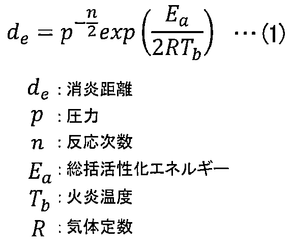
副室42内、特に細い円管状の連通路43内では、副室42の壁温(副室温度)が火炎温度Tbに大きく影響する。副室温度が低い場合、連通路43内の火炎温度Tbが著しく低下し、消炎距離deが増加する。その結果、消炎距離deが連通路43の直径を超えると、副室42で発生した火炎が消炎してしまう。図7では、副室42と連通路43の壁面に沿って、壁面から消炎距離deだけ離れた領域が消炎領域80として示される。
次に、ECU2によって行われる副室温度に基づいた副室内圧力の制御方法について説明する。
図8は、副室温度と副室内圧力との関係を示す図である。図8に示すグラフの横軸が副室温度、縦軸が副室内圧力を表す。
図8は、副室温度と副室内圧力との関係を示す図である。図8に示すグラフの横軸が副室温度、縦軸が副室内圧力を表す。
図8には、副室温度と副室内圧力との関係が実線81で示される。また、消炎距離が一定となる副室温度と副室内圧力との関係が、破線の消炎距離一定ラインで表される。実線81の上側は火炎伝播可能領域82を表し、実線81の下側は消炎領域83を表す。火炎伝播可能領域82と消炎領域83を分ける実線81は、連通路43の直径(「連通路径」とも呼ぶ)によって定まる。
副室温度と副室内圧力との関係が火炎伝播可能領域82にあれば、副室42で発生した火炎は連通路43を通過して主室37に到達し、主室37内の混合気を着火する。しかし、副室温度と副室内圧力との関係が消炎領域83にあれば、副室42で発生した火炎は連通路43の通過中に消炎してしまい、主室37内の混合気を着火できない。
すなわち、実線81より、副室温度が低い領域では副室内圧力も低いので、消炎領域83が生じているのに対し、副室温度が高くなると低い副室内圧力でも火炎伝播可能領域82に至ることが示される。そこで、ECU2は、副室温度に基づいて、副室内圧力を実線81に示すように制御する。例えば、ECU2は、消炎距離が一定値未満となるように、副室温度が低い時ほど、副室内圧力が高くなるようにエンジン13を制御する。この制御により、連通路43内の消炎を抑制し、燃焼安定化を実現することが可能となる。
ここで、ECU2によって行われるエンジン運転点の制御方法について説明する。エンジン運転点とは、ECU2がエンジン13を運転するときに設定されるエンジン回転数とエンジントルクとを表す。ただし、エンジン運転点を、インバータ15を駆動して発電し、バッテリ16を充電するときの発電点と読み替えてもよい。
図9は、副室温度に基づいたエンジン運転点を示す図である。図9に示すグラフの横軸がエンジン回転数、縦軸がエンジントルクを表す。
前述の通り、本実施の形態に係るECU2(制御部22)は、例えば、エンジン13の始動時等で副室温度が低い時(=冷機時)には、副室内圧力を高めるように制御する。そこで、ECU2は、副室内圧力を高めるために、エンジン13の吸気圧力を上昇させ、エンジン13のエンジントルクを高める制御を行う。
ただし、ECU2がエンジントルクを高めると、その分エンジン出力、つまり発電量も変化してしまう。このため、ECU2は、エンジントルクを高めた分、エンジン回転数を減少させ、エンジン出力を一定に保つように制御する。この制御における、エンジン回転数とエンジントルクとの関係は、図9に破線で示す等出力ラインで表される。
ECU2の制御部22は、以下のようにエンジン運転点(発電点)の制御を行う。
エンジン13の始動直後など冷機時においては、制御部22は、エンジン運転点を、エンジントルクを高めた冷機時のA点に設定する。その後、エンジン回転数が上がると、制御部22は、副室温度の上昇に伴って、エンジントルクを低くし、エンジン回転数を高めた通常時のB点に移行させる。このように制御部22は、等出力ラインに沿ってエンジン運転点をA点からB点に移行させるように制御することで、エンジン出力を一定に保つことができる。
エンジン13の始動直後など冷機時においては、制御部22は、エンジン運転点を、エンジントルクを高めた冷機時のA点に設定する。その後、エンジン回転数が上がると、制御部22は、副室温度の上昇に伴って、エンジントルクを低くし、エンジン回転数を高めた通常時のB点に移行させる。このように制御部22は、等出力ラインに沿ってエンジン運転点をA点からB点に移行させるように制御することで、エンジン出力を一定に保つことができる。
次に、エンジン冷却水温度と副室温度の関係について説明する。
図10は、エンジン冷却水温度と副室温度の関係を示す図である。図10に示すグラフの横軸がエンジン冷却水温度、縦軸が副室温度を表す。この図を用いて本実施例の形態に係る推定部21で行われる副室温度の推定方法を説明する。
図10は、エンジン冷却水温度と副室温度の関係を示す図である。図10に示すグラフの横軸がエンジン冷却水温度、縦軸が副室温度を表す。この図を用いて本実施例の形態に係る推定部21で行われる副室温度の推定方法を説明する。
図10に示すグラフは、エンジン13の始動直後(冷機)からエンジン13が暖機されるまでの期間について、エンジン冷却水温度と副室温度とをプロットしたものである。エンジン13の始動直後において、副室温度は冷却水温度と強い相関が見られる。このため、ECU2の推定部21は、図10に示す相関関係を用いて、冷却水温度センサ9cが計測し、VCU1が計算した冷却水温度から副室温度を推定する。そして、制御部22は、推定部21が推定した副室温度と、図8より副室温度から求められる副室内圧力との関係が、図8に示した消炎領域83にかからないように、エンジントルク及びエンジン回転数を制御する。
図11は、副室内圧力の制御方法の例を示すフローチャートである。
始めに、ECU2の制御部22は、エンジン13が始動されてからの経過時間であるエンジン駆動時間をRAM2cから読み込む(S1)。次に、制御部22は、エンジン駆動時間teが所定値tth未満であるか、つまり、エンジン13が始動直後の過渡状態か否かを判定する(S2)。エンジン13の始動後十分に時間が経っている場合(S2のNO)、すなわち、エンジン駆動時間teが所定値tth以上であれば、制御部22は、定常状態であると判定する。そして、制御部22は、通常運転モードとして通常エンジン運転点(B点)を設定し(S3)、本処理に係る制御を終了する。
一方、エンジン13の始動後十分に時間が経っていない場合(S2のYES)、すなわち、エンジン駆動時間teが所定値tth未満であれば、過渡状態(冷機運転モード)であると判定する。ここで、VCU1が冷却水温度センサ9cの出力信号に基づいて演算した冷却水温度TcがECU2に出力され、ECU2のRAM2cに冷却水温度Tcが記憶されているとする。このため、推定部21は、RAM2cから冷却水温度Tcを読み込む(S4)。次に、推定部21は、冷却水温度Tcに基づき、図10に示したエンジン冷却水温度と副室温度の関係に基づいて、副室温度を推定する演算を行う(S5)。
次に、推定部21は、ステップS5で推定した副室温度に基づき、図8に示した副室温度と副室内圧力の関係に基づき、エンジン13に要求する副室内圧力(「要求副室内圧力」と呼ぶ)を演算する(S6)。そして、制御部22は、図9に示したエンジン回転数とエンジントルクの関係に基づき、冷機時のエンジン運転点(A点)を設定する(S7)。
最後に、制御部22は、ステップS7で設定したエンジン運転点(A点)を実現するための吸気圧力制御(スロットル開度制御)を実行して(S8)、本処理に係る一連の制御を終了する。
図12は、副室内圧力の制御方法の例を示すタイムチャートである。図12に示すタイムチャートは、上から順に、冷却水温度、推定副室温度、要求副室内圧力、エンジントルク・エンジン回転数設定値、吸気圧力(スロットル開度)について、図11に示した制御方法による、エンジン13の始動後からの時間変化を示している。
エンジン13の始動直後は、冷却水温度、推定副室温度が低い状態である。エンジン13が駆動すると冷却水温度が上昇し、推定部21が冷却水温度から推定した副室温度も上昇していく。副室温度の上昇に伴い、消炎を防止するために必要な要求副室内圧力が低下する。さらに、要求副室内圧力の低下に伴って、エンジントルクの設定値が減少する。
制御部22は、エンジン出力(発電量)を一定に保つため、エンジントルクの減少に伴い、エンジン回転数の設定値を上昇させる。そこで、制御部22は、設定されたエンジントルク及びエンジン回転数を実現するために吸気圧力(スロットル開度)が低くなるように制御する。このため、制御部(制御部22)は、副室温度が設定温度以上になった場合に、内燃機関(エンジン13)のシリンダ内圧力(シリンダ38内の圧力)が低くなるように内燃機関(エンジン13)を制御する。
以上説明した第1の実施の形態に係るECU2では、推定部21が、エンジン冷却水温度に基づいて副室温度を推定し、副室温度と副室内圧力との関係に基づいて副室内圧力を推定する。そして、制御部22が、エンジン13の始動時(冷機時)には、副室内圧力が大きくなるように、低いエンジン回転数で大きいエンジントルクを設定した運転点でエンジン13を制御する。その後、エンジン13が通常状態に移行すると、制御部22は、高いエンジン回転数で小さいエンジントルクを設定した運転点でエンジン13を制御する。
このような制御により、副室42の消炎が抑制され、さらにエンジン13の燃焼変動も抑制することができ、エンジン出力も一定に保つことができる。
このような制御により、副室42の消炎が抑制され、さらにエンジン13の燃焼変動も抑制することができ、エンジン出力も一定に保つことができる。
[第2の実施の形態]
次に、図13を用いて、本発明の第2の実施の形態に係るECUについて説明する。本実施の形態に係る、システム構成、ハードウェア構成、副室温度の推定方法については第1の実施形態と同一である。
次に、図13を用いて、本発明の第2の実施の形態に係るECUについて説明する。本実施の形態に係る、システム構成、ハードウェア構成、副室温度の推定方法については第1の実施形態と同一である。
図13は、第2の実施の形態に係るエンジン運転点の例を示す図である。第2の実施形態に係るECU2は、副室温度が低い冷機時において、ハイブリッド自動車100自体の状況や、ハイブリッド自動車100の環境状況等を表す車両状態に応じて2つの異なる運転点(A-1点、A-2点)を設定することが特徴である。
A-1点、A-2点は、共に、副室温度が高い状態の通常運転(B点)よりもエンジントルクが大きい設定とした運転点を表す。このため、冷機時には、制御部22が、A-1点、A-2点でエンジン回転数及びエンジントルクを維持することで、副室内圧力を高め、副室42の消炎を抑制することが可能である。
なお、A-1点は、通常運転点(B点)と同じエンジン出力(同発電量)となる運転点を表す。制御部22は、発電量の需要が高くない条件、例えば暖房用運転等において、A-1点を活用することで、バッテリ16の電池残量を適正に保ちながら、エンジン13を駆動することが可能である。
A-2点は、B点に示す通常運転時(B点)よりもエンジン出力(発電量)が大きい運転点である。A-2点と、B点とは、共にエンジン回転数が等しい等エンジン回転数ラインの上(一点鎖線で示すライン上)にある。
制御部22は、発電量の需要が高い条件、例えば高速道路の走行時などにおいて、A-2点を活用することで、バッテリ16の電池残量を適正に保ちながら、エンジン13を駆動することが可能である。より具体的には、図13の下の表に示すように、バッテリ16の電池残量、走行シーン、副室温度域によって、制御部22が、A-1点、A-2点又はB点のいずれかの運転点に切り替える。以下に、図13の下の表を参照して、3種類の制御の例を説明する。
<充電率(SOC)に基づく制御の例>
始めに、電池残量(Ah)/満充電容量(Ah)×100で表されるバッテリ16の充電率(SOC)に基づいて、制御部22がエンジン運転点を変える制御について説明する。制御部22は、VCU1からバッテリ16のSOCを受け取ることが可能である。そして、制御部(制御部22)は、副室温度が低く、かつ発電機(ジェネレータ14)により充電される電池(バッテリ16)の充電率(SOC)が低いほど、内燃機関回転数(エンジン回転数)が大きくなるように内燃機関(エンジン13)を制御する。
始めに、電池残量(Ah)/満充電容量(Ah)×100で表されるバッテリ16の充電率(SOC)に基づいて、制御部22がエンジン運転点を変える制御について説明する。制御部22は、VCU1からバッテリ16のSOCを受け取ることが可能である。そして、制御部(制御部22)は、副室温度が低く、かつ発電機(ジェネレータ14)により充電される電池(バッテリ16)の充電率(SOC)が低いほど、内燃機関回転数(エンジン回転数)が大きくなるように内燃機関(エンジン13)を制御する。
ここで、制御部(制御部22)は、発電機(ジェネレータ14)により充電される電池(バッテリ16)の充電率(SOC)が第1設定充電率(第1設定SOC:下限値SL)未満の場合に、内燃機関回転数(エンジン回転数)が第2設定回転数(A-2点のエンジン回転数)となるように内燃機関(エンジン13)を制御することで、発電を促進する。
そして、制御部(制御部22)は、副室温度が設定温度以上になった場合(通常時)に、内燃機関回転数(エンジン回転数)をほぼ第2設定回転数(A-2点のエンジン回転数)のまま維持しつつ、内燃機関トルク(エンジントルク)を低下させ、通常時の運転点(B点)に移行するように内燃機関(エンジン13)を制御する。
そして、制御部(制御部22)は、副室温度が設定温度以上になった場合(通常時)に、内燃機関回転数(エンジン回転数)をほぼ第2設定回転数(A-2点のエンジン回転数)のまま維持しつつ、内燃機関トルク(エンジントルク)を低下させ、通常時の運転点(B点)に移行するように内燃機関(エンジン13)を制御する。
また、制御部(制御部22)は、発電機(ジェネレータ14)により充電される電池(バッテリ16)の充電率(SOC)が第1設定充電率(第1設定SOC:下限値SL)以上の場合に、内燃機関回転数(エンジン回転数)が第1設定回転数(A-1点のエンジン回転数)となるように内燃機関(エンジン13)を制御する。つまり、充電率(SOC)が下限値SL以上かつ上限値SH未満の場合、制御部22は、A-1点を設定し、充電率(SOC)を一定範囲に保つ。そして、制御部(制御部22)は、副室温度が設定温度以上になった場合(通常時)に、内燃機関回転数(エンジン回転数)を第1設定回転数(A-1点のエンジン回転数)よりも高い第2設定回転数(B点のエンジン回転数)まで上昇させ、かつ内燃機関トルク(エンジントルク)を低下させることで、発電機(ジェネレータ14)の出力がほぼ一定となるように内燃機関(エンジン13)を制御する。
SOCが上限値SH以上になると、バッテリ16への充電は不要である。このため、制御部22は、エンジン13を停止し、発電量を0にする(図中ではエンジン運転点をOFFと記載する)。つまり、制御部(制御部22)は、充電率(SOC)が、第1設定充電率(第1設定SOC:下限値SL)より高い第2設定充電率(第2設定SOC:上限値SH)以上になった場合に、内燃機関(エンジン13)の動作を停止させるように制御する。
<走行シーンに基づく制御の例>
次に、ナビゲーション装置11から得られるハイブリッド自動車100の現在位置に対する環境情報に基づいて推定部21が判定した走行シーンにより、制御部22がエンジン運転点を変える制御について説明する。
次に、ナビゲーション装置11から得られるハイブリッド自動車100の現在位置に対する環境情報に基づいて推定部21が判定した走行シーンにより、制御部22がエンジン運転点を変える制御について説明する。
一般に高速道路では、ハイブリッド自動車100の高速走行(例えば、時速80km以上での走行)が許容される。しかし、高速道路以外の一般道路では、高速道路で許容される速度より低い速度に制限される。このため、ハイブリッド自動車100が高速道路を走行している場合、高出力走行により、バッテリ16の電力消費が大きいことが予想される。そこで、制御部(制御部22)は、内燃機関(エンジン13)を備える自動車(ハイブリッド自動車100)が高速道路を走行中である場合に、自動車(ハイブリッド自動車100)が一般道路(郊外)を走行中である場合に比べて、内燃機関回転数(エンジン回転数)が大きくなるように内燃機関(エンジン13)を制御する。
具体的には、制御部22は、ハイブリッド自動車100が高速道路を走行中に、運転点をA-2点とし、発電量を増加させる。しかし、ハイブリッド自動車100が郊外の幹線道路を走行中には、高速道路の走行に比べてバッテリ16の電力消費が大きくないことから、制御部22は、運転点にA-1点を設定してバッテリ16の電池残量を一定範囲に保つ。また、ハイブリッド自動車100が市街地を走行中であれば、高速道路及び郊外の走行時に比べてさらに速度が低下するので、バッテリ16の電力消費も減少する。このため、制御部22は、エンジン13を停止し、発電量を0にする(図中ではエンジン運転点をOFFと記載する)。
<副室温度に基づく制御の例>
次に、推定部21が推定した副室温度Tpcに基づいて、制御部22がエンジン運転点を変える制御について説明する。
次に、推定部21が推定した副室温度Tpcに基づいて、制御部22がエンジン運転点を変える制御について説明する。
推定部21が推定した副室温度Tpcが下限値TL未満の場合、制御部22は、A-2点を設定して高出力運転することで副室温度を早期に昇温させる。副室温度Tpcが下限値TL以上かつ上限値TH未満の場合、制御部22は、A-1点を設定し、燃焼安定性を保ちつつ、SOCを一定範囲内に保つように制御する。副室温度Tpcが上限値TH以上になると、十分に暖気された後であるので、制御部22は、通常運転時のB点を設定する。
以上説明した第2の実施の形態に係るECU2では、推定部21が推定したハイブリッド自動車100の車両状態(電池残量、副室温度)や走行シーンに基づき、制御部22が運転点を切り替える制御を行う。このような制御により、エンジン13の始動時における燃焼安定性を確保しつつ、バッテリ16の電池残量を適正に保ち、さらに副室温度を早期に上昇させることが可能となる。
[第3の実施の形態]
次に、図14から図18を用いて、本発明の第3の実施の形態に係るECUについて説明する。
本実施形態に係る、システム構成、副室温度推定方法については第1の実施形態と同一である。本実施形態に係るECU2は、図14に示すようにインテークマニホールド31に燃料噴射装置36を設け、さらに副室42に燃料噴射装置36Aを設けた構成としたエンジン13において、連通路43の有効径(以下、「有効連通路径」と呼ぶ)に基づいて、副室内圧力を制御することを特徴とする。
次に、図14から図18を用いて、本発明の第3の実施の形態に係るECUについて説明する。
本実施形態に係る、システム構成、副室温度推定方法については第1の実施形態と同一である。本実施形態に係るECU2は、図14に示すようにインテークマニホールド31に燃料噴射装置36を設け、さらに副室42に燃料噴射装置36Aを設けた構成としたエンジン13において、連通路43の有効径(以下、「有効連通路径」と呼ぶ)に基づいて、副室内圧力を制御することを特徴とする。
図14は、第3の実施の形態に係る点火装置50及び副室42の設置例を示す図である。第3の実施の形態に係る点火プラグ40Bは、副室形成部材45の側面に燃料噴射装置36Aが取り付けられた構成としている。つまり、内燃機関(エンジン13)は、副燃焼室(副室42)内に燃料を直接噴射する第2燃料噴射装置(燃料噴射装置36A)を備えている。
燃料噴射装置36Aが副室42内で噴射した燃料に対して電極41で発生した火花放電で着火した火炎が、副室形成部材45に形成された連通路43を通過して複数の火炎ジェット44として噴出する。なお、第1の実施の形態に係るエンジン13と同様に、インテークマニホールド31にも燃料噴射装置36が設けられている。燃料噴射装置36が噴射した燃料は、主室37内に充満した後、副室42の連通路43から噴出した火炎ジェット44により多点着火される。
副室42には、副室内圧力を計測する圧力センサ46が備えられている。副室内圧力は、後述する図17で説明するように、推定部21が有効連通路径を推定するために用いられる。このため、第3の実施の形態に係るECU2が備える推定部21は、副燃焼室(副室42)に設けられた連通路43の有効連通路径を推定する。そして、制御部22は、推定部21が推定した有効連通路径に基づいて、副室内圧力を制御する。例えば、制御部(制御部22)は、推定された有効連通路径が、所定値以下になった場合に、第2燃料噴射装置(燃料噴射装置36A)に燃料噴射を実施させない制御を行う。
図15は、副室42と主室37間の有効連通路径Deffの例を示す図である。
連通路43の直径は、主室37内で安定かつ高速な燃焼が実現できるよう、エンジン13毎に最適に設計される。しかし、エンジン13の使用に伴い、連通路43の内部に、燃料やスス等の不完全性燃焼生成物が堆積する。このように連通路43の内部に堆積した不完全性生成物を「燃焼デポジット」と呼ぶ。そして、連通路43の表面に堆積した燃焼デポジット47の間の幅を有効連通路径Deffと呼ぶ。連通路43に燃焼デポジットが発生していなければ、連通路43の直径がそのまま有効連通路径Deffとなる。しかし、燃焼デポジットが発生すると、有効連通路径Deffが狭まる。そして、有効連通路径Deffが所定値以下になった場合に、連通路43を通過して主室37に噴出する火炎ジェット44も弱まったり、消炎したりする。また、燃焼デポジット47の堆積などの経年変化や、製造ばらつきによる副室42の個体差によって、有効連通路径Deffは副室42の個体ごとにばらつき、かつリアルタイムに変化する。
また、燃焼デポジット47は、燃料が副室42内に付着したり、空気と燃料が不完全に混合したりすることで発生する。このため、特に副室42内に燃料噴射装置36Aを備えたエンジン13において、燃焼デポジット47が顕著に発生する可能性がある。そして、有効連通路径Deffが減少するに伴い、連通路43内で火炎ジェット44が消炎する頻度が高くなる。そこで、有効連通路径Deffに基づいて、副室内圧力を変える制御が必要となる。
図16は、有効連通路径Deffと、主燃焼中心時期、及び主室37と副室42の間の最大差圧との関係を示す図である。
連通路43に燃焼デポジット47が堆積するなどして有効連通路径Deffの減少が発生すると、主室37における主燃焼中心時期が遅延し、主室37と副室42間の最大差圧が大きくなる傾向がある。したがって、推定部21は、有効連通路径Deffの変化を、主室37における主燃焼中心時期や、主室37と副室42間の最大差圧から推定することができる。
図17は、有効連通路径Deffと副室内圧力との関係を示す図である。
有効連通路径Deffが、第1の実施の形態にて既に説明した火炎の消炎距離de(図7を参照)を下回ると、連通路43内での消炎が発生する。そこで、連通路43内での消炎を回避するためには、制御部22が、有効連通路径Deffが小さくなるに従い、副室内圧力を大きくする制御を行って、消炎距離を短くする。このような制御により、ECU2が連通路43内での消炎を防ぐことができる。
次に、有効連通路径Deffに基づいて行われる副室内圧力の制御方法の例について説明する。
図18は、副室内圧力の制御方法の例を示すフローチャートである。
図18は、副室内圧力の制御方法の例を示すフローチャートである。
始めに、推定部21は、VCU1が冷却水温度センサ9cの出力信号に基づいて演算した冷却水温度TcをRAM2cから読み込む(S11)。そして、推定部21は、図10に示した冷却水温度と副室温度との関係に基づいて冷却水温度Tcから副室温度Tpcを推定する演算を行う(S12)。
次に、推定部21は、推定した副室温度Tpcを所定値Tthと比較し、副室温度Tpcが所定値Tth未満であるか否かを判定する(S13)。副室温度Tpcが所定値Tth以上であると判定した場合(S13のNO)、制御部22は、通常エンジン運転点(例えば、B点)を設定して(S14)、本処理による制御を終了する。
一方、推定部21が、副室温度Tpcが所定値Tth未満であると判定した場合(S13のYES)、副室42内に設置された圧力センサ46の値(副室内圧力)を、RAM2cから読み込む(S15)。そして、推定部21は、読み込んだ副室内圧力に基づいて、副燃焼室(副室42)の内圧と主燃焼室(主室37)の内圧との最大差圧、及び主燃焼中心時期のうち、少なくとも1つを演算する(S16)。
次に、推定部21は、副燃焼室(副室42)の内圧と主燃焼室(主室37)の内圧とから演算される最大差圧、及び主燃焼中心時期のうち、少なくとも1つに基づいて、図16に示した関係を用いて、有効連通路径Deffを推定する(S17)。
次に、制御部22は、推定された有効連通路径Deffに基づき、図17に示した有効連通路径と副室内圧力との関係を用いて、要求副室圧力を演算する(S18)。その後、制御部22は、要求副室圧力を実現するために冷機時のエンジン運転点(エンジントルク、エンジン回転数)を設定する(S19)。
最後に、制御部22は、ステップS19で設定したエンジン運転点を実現するための吸気圧力制御(スロットル開度制御)を実行する(S20)。つまり、制御部(制御部22)は、副室温度(副室温度Tpc)が温度設定値(所定値Tth)未満の場合に、推定された有効連通路径が小さいほど、内燃機関(エンジン13)の点火時期近傍での副燃焼室内圧力(副室内圧力)が高くなるように内燃機関(エンジン13)を制御する。その後、制御部22は、本処理に係る一連の制御を終了する。
以上説明した第3の実施の形態に係るECU2では、有効連通路径Deffの変化に対応して、副室内圧力を制御することが可能となる。このため、ECU2は、エンジン13の冷機運転時における連通路43内での消炎を未然に防止することが可能となる。
[第4の実施の形態]
次に、図19から図21を用いて、本発明の第4の実施の形態に係るECUについて説明する。
本実施形態に係る、システム構成及びハードウェア構成については第1の実施形態と同一である。本実施形態に係るECU2は、点火装置50に通電される1次電流、電圧信号を用いて推定した副室温度に基づいて、エンジン13を制御する。以下に点火装置50の構成例と、燃焼変動率を抑える制御の方法について説明する。
次に、図19から図21を用いて、本発明の第4の実施の形態に係るECUについて説明する。
本実施形態に係る、システム構成及びハードウェア構成については第1の実施形態と同一である。本実施形態に係るECU2は、点火装置50に通電される1次電流、電圧信号を用いて推定した副室温度に基づいて、エンジン13を制御する。以下に点火装置50の構成例と、燃焼変動率を抑える制御の方法について説明する。
図19は、点火装置50の構成例を示す図である。
点火装置50は、点火部51、1次電流検出部55、ダイオード57及び抵抗58を備える。点火装置50が備える各部は、各シリンダ38が備える点火装置50のプラグキャップ内にまとめて配置される。
点火装置50は、点火部51、1次電流検出部55、ダイオード57及び抵抗58を備える。点火装置50が備える各部は、各シリンダ38が備える点火装置50のプラグキャップ内にまとめて配置される。
そして、点火部(点火部51)は、1次電流が通電される1次コイル(1次コイル52)と、点火制御信号がオンされたときに1次コイル(1次コイル52)に1次電流を通電し、点火制御信号がオフされたときに1次電流を遮断するイグナイタ(イグナイタ54)と点火制御信号がオフされたイグナイタ(イグナイタ54)が1次電流を遮断したことで発生する2次電流を電極(電極41)に出力する2次コイル(2次コイル53)と、を含む。
1次コイル52には、例えば、バッテリ16から+12Vの電圧が印加されて、1次電流が流れる。1次コイル52と2次コイル53は、点火プラグ40に高圧電流を与えるイングニッションコイルの一例である。また、1次コイル52に対する2次コイル53の巻き数比は、例えば、100倍である。
ECU2からイグナイタ54に供給される点火制御信号がオンされている間、バッテリ16(図1を参照)から供給される1次電流が、点火部51の1次コイル52を経て、イグナイタ54のコレクタからエミッタに出力される。エミッタは、1次電流検出部55に設けられた抵抗56を介して接地されている。1次電流検出部(1次電流検出部55)は、抵抗56を通電される1次電流を検出すると、ECU2に1次電流の値を含む点火装置情報を出力する。
一方、2次コイル53の一端は点火プラグ40の電極41に接続され、2次コイル53の他端はダイオード57のアノードに接続される。ダイオード57のカソードは、抵抗58を介して接地されている。
ECU2から供給される点火制御信号がオフされると、イグナイタ54を流れる1次電流が遮断される。このとき、1次コイル52には磁界変化が発生し、自己誘導により1次電圧が発生する。さらに、1次コイル52と磁気回路及び磁束を共有する2次コイル53には相互誘導により、巻き数比に応じた高い2次電圧が発生する。
そして、2次電圧が点火プラグ40の電極41に印加され、電極41で火花放電が発生する。また、2次コイル53に2次電圧が誘起されて発生した2次電流が、ダイオード57、抵抗58を流れる。
図20は、ECU2及び点火装置50の機能構成例を示すブロック図である。
ECU2は、推定部21と制御部22とを備える。
ECU2は、推定部21と制御部22とを備える。
推定部21(推定部21)は、点火プラグ(点火プラグ40)を点火する点火装置(点火装置50)から出力される点火装置情報に基づいて副燃焼室(副室42)の温度を推定する。この推定部(推定部21)は、図19に示した点火部51の1次コイル(1次コイル52)にエネルギーをチャージするチャージ期間における1次電流の時間変化に基づいて副燃焼室(副室42)の温度を推定できる。例えば、推定部(推定部21)は、点火制御信号がオン又はオフされたことで、1次電流検出部(1次電流検出部55)が検出する1次電流の変化に基づいて、副燃焼室(副室42)の温度を推定する。
点火制御部(制御部22)は、図19に示したイグナイタ(イグナイタ54)のオン又はオフを切り替える点火制御信号を点火装置(点火装置50)に出力する。この点火制御信号により、イグナイタ54が1次電流を通電し、又は遮断するタイミングが切り替わり、点火部51が点火プラグ40を点火するタイミングが制御される。そして、1次電流が遮断されると、2次コイル53が昇圧し、点火プラグ40の電極41に高電圧を印加して、電極41から火花放電が発生する。
図21は、点火制御信号、1次電流及び1次電圧の変化を示すグラフである。ここでは、図19に示した点火装置50の回路図を参照して説明する。
図21の上側には、制御部22が、点火制御信号をオフからオンした後、再びオフしたタイミングが示される。点火制御信号がオフされると、点火プラグ40が点火することが図中に示される。
図21の中側には、1次電流検出部55が点火プラグ40の1次電流を検出して得た電流波形、及び1次電圧の電圧波形のグラフが示される。1次電流のグラフ61では、副室温度が低温の時における1次電流の変化を実線で表し、グラフ62では、副室温度が高温の時における1次電流の変化を破線で表す。1次電流及び1次電圧の時間変化は、1次電流検出部55が検出した1次電流の値を含む点火装置情報を受け取った推定部21が判断する。
1次電流の電流波形に示すように、副室温度が低温の時には、1次コイル52のコイル抵抗が低いので、1次電流が1次コイル52を流れやすい。このため、時間t11にて点火制御信号がオンされてから、1次コイル52に1次電流のエネルギーがチャージされるまでに要する時間が短く、図中に領域61aとして示すように1次電流の傾きが急である。
一方で、副室温度が高温になると、1次コイル52のコイル抵抗が高くなり、1次電流が1次コイル52を流れにくくなる。このため、時間t11にて点火制御信号がオンされてから、1次コイル52に1次電流のエネルギーがチャージされるまでに要する時間が長くなり、1次電流の傾きが鈍化する。
また、副室温度が低温の時には、図中に領域62aとして示すように、時間t12にて点火制御信号がオフに変化したときに、1次電流の値が、点火制御信号をオンする前と同じ値にすぐ戻る。一方で、副室温度が上がると、1次コイル52のインダクタンスが増加し、1次電流のアンダーシュート量も増加する。
図21の下側には、図21の領域62aの拡大図が示される。この拡大図では、副室温度が低温、中温、高温の時に1次電流が時間変化する様子が示される。図21の下側より、副室温度が上昇するにつれて、1次電流のアンダーシュート量が増加し、1次電流の値が、点火制御信号をオンする前と同じ値に戻るまでに時間がかかることが分かる。
そこで、推定部(推定部21)は、点火制御信号がオフされて1次電流が、点火制御信号がオンされる前の値に戻るときのアンダーシュート量が多くなるほど、副燃焼室(副室42)の温度が高いと推定する。
なお、図21の中側に示す1次電圧のグラフ63では、副室温度が低温の時における1次電圧の変化を実線で表し、グラフ64では、副室温度が高温の時における1次電圧の変化を破線で表す。また、1次電圧の電圧波形に示すように、副室温度が低温の時と、高温の時とで、時間t11にて点火制御信号がオンされてから、1次コイル52に1次電流のエネルギーがチャージされるまでの1次電圧は同じように変化する。
しかし、時間t12にて点火制御信号がオフされたタイミングで、副室温度が低温である方の1次電圧が、副室温度が高温である方の1次電圧よりも高くなるように変化する。
その後、副室温度が高温の時に1次電圧が、点火制御信号がオンされる前の値に戻る時間は、副室温度が低温の時に元の値に戻る時間よりも長くなる。そこで、推定部21は、1次電流検出部55が検出した1次電流を1次電圧に変換して1次電圧の変化を求めることで、副室温度を判断できる。
その後、副室温度が高温の時に1次電圧が、点火制御信号がオンされる前の値に戻る時間は、副室温度が低温の時に元の値に戻る時間よりも長くなる。そこで、推定部21は、1次電流検出部55が検出した1次電流を1次電圧に変換して1次電圧の変化を求めることで、副室温度を判断できる。
そして、推定部(推定部21)は、点火制御信号がオフされて1次コイル(1次コイル52)に印加される1次電圧が、点火制御信号がオンされる前の値に戻るまでの時間が長くなるほど、副燃焼室(副室42)の高温であると推定する。その後、制御部(制御部22)は、推定された副室温度に基づいて、図8に示した関係により副室内圧力を演算し、制御部(制御部22)が、図9の関係により副室温度に合わせて、エンジン13のエンジントルク及びエンジン回転数を制御する。
以上説明した第4の実施の形態に係るECU2では、推定部21が点火装置情報から求めた、点火装置50の1次電流及び1次電圧の変化に基づいて、副室温度を推定する。そして、制御部22が、推定された副室温度に合わせてエンジン13を所定の運転点で制御する。このため、ECU2は、エンジン13の冷機運転時における消炎を未然に防止し、燃焼変動を抑制することが可能となる。
[第5の実施の形態]
次に、図22と図23を用いて、本発明の第5の実施の形態に係るECUについて説明する。
本実施形態に係るECUの構成については第1の実施形態と同一である。本実施形態においては、演算部が燃焼変動率を検知し、制御部が燃焼変動率に応じた吸気圧力のフィードバック制御を実施することを特徴とする。以下、本実施の形態に係る推定部21が、図3の説明図(2)に示した、副室42内に圧力センサ46が設置された点火プラグ40Aを備えるエンジン13の燃焼変動状態を表す燃焼変動率を推定し、エンジン13を制御する方法について説明する。
次に、図22と図23を用いて、本発明の第5の実施の形態に係るECUについて説明する。
本実施形態に係るECUの構成については第1の実施形態と同一である。本実施形態においては、演算部が燃焼変動率を検知し、制御部が燃焼変動率に応じた吸気圧力のフィードバック制御を実施することを特徴とする。以下、本実施の形態に係る推定部21が、図3の説明図(2)に示した、副室42内に圧力センサ46が設置された点火プラグ40Aを備えるエンジン13の燃焼変動状態を表す燃焼変動率を推定し、エンジン13を制御する方法について説明する。
図22は、副室内圧力の制御方法の例を示すフローチャートである。ここで、図22のステップS21~S28までの処理は、第1の実施の形態に係るステップS1~S8までの処理と同じであるので、詳細な説明を省略する。
ステップS28で制御部22が、吸気圧力制御(スロットル開度制御)を実行した後、推定部21は、副室42内に設置された圧力センサ46が検知した副室内圧力に基づいて、燃焼変動状態の一例である燃焼変動率を推定するための演算を行う(S29)。次に、制御部22は、演算された燃焼変動率を、予め定められた閾値と比較し、燃焼変動率が閾値未満であるか否かを判定する(S30)。
燃焼変動率が閾値未満である場合(S30のYES)、制御部22は、火炎ジェット44が消炎していないと判断し、例えば、RAM2cに領域を確保した消炎フラグに“0”をセットし、本処理に係る一連の制御を終了する。
制御部(制御部22)は、推定された内燃機関(エンジン13)の燃焼変動状態(燃焼変動率)が、閾値以上である場合(S30のNO)、制御部22は、火炎ジェット44が消炎していると判断し、消炎フラグに“1”をセットする。そして、制御部(制御部22)は、内燃機関トルク(エンジントルク)が大きくなるように、エンジン13の設定トルクを増加し(S31)、内燃機関(エンジン13)によって駆動され、発電した電力を電池(バッテリ16)に充電する発電機(ジェネレータ14)を制御する。その後、制御部22は、再び吸気圧力の制御へ進む(S28)。ステップS28~S31の制御は、燃焼変動率が閾値以下になるまで繰り返し実行される。
図23は、副室内圧力の制御方法の例を示すタイムチャートである。このタイムチャートは、燃焼変動率、消炎フラグ、設定エンジントルク(図中では「トルク」と記載)、設定エンジン回転数(図中では「回転数」と記載)、吸気圧力(スロットル開度)の時間変化を示している。
最初は、エンジン13が停止しているので燃焼変動率が破線で表す閾値未満であり、消炎フラグが“0”にセットされている。そして、エンジントルク、エンジン回転数及び吸気圧力は、いずれも“0”である。
時刻t1においてエンジン13が始動すると、推定部21は、燃焼変動率を演算する。
図23に示した例では、時刻t1の直後に燃焼変動率が閾値よりも高くなったことが示される。このため、制御部22は、消炎フラグを“1”にセットする。そして、制御部22は、エンジントルクの設定値を増加させ、エンジントルクが増加するように、吸気圧力を高く(スロットル開度を大きく)なるように制御する。このような制御により、燃焼変動率が低下し、エンジン回転数も低下する。
図23に示した例では、時刻t1の直後に燃焼変動率が閾値よりも高くなったことが示される。このため、制御部22は、消炎フラグを“1”にセットする。そして、制御部22は、エンジントルクの設定値を増加させ、エンジントルクが増加するように、吸気圧力を高く(スロットル開度を大きく)なるように制御する。このような制御により、燃焼変動率が低下し、エンジン回転数も低下する。
時刻t2の時点で、推定部21により演算された燃焼変動率が閾値未満になる。そこで、制御部22は、消炎フラグを“0”にセットする。そして、制御部22は、エンジントルク設定値及び吸気圧力を一定に制御する。
以上説明した第5の実施の形態に係るECU2では、推定部21がリアルタイムで推定した燃焼変動率に基づいて、制御部22が消炎を判断し、副室内圧力を制御する。このため、ECU2は、エンジン13の部品ばらつきや環境変化に対してロバストな燃焼安定制御を実行することが可能となる。
なお、第5の実施の形態に係る推定部21は、クランク角センサ9bが検出したクランク軸の回転角度の変動に基づいて、燃焼変動率を推定することも可能である。
[第6の実施の形態]
次に、図24から図26を用いて、本発明の第6の実施の形態に係るECUについて説明する。本実施形態においては、ハイブリッド自動車ではなく、エンジン13のみの駆動力によって駆動するガソリン自動車に対して本発明を適用している点が特徴である。また、ECU2は、エンジン13の有効圧縮比を制御することで、エンジントルク及びエンジン回転数を変化させずに、副室内圧力を好適に制御することが特徴である。
次に、図24から図26を用いて、本発明の第6の実施の形態に係るECUについて説明する。本実施形態においては、ハイブリッド自動車ではなく、エンジン13のみの駆動力によって駆動するガソリン自動車に対して本発明を適用している点が特徴である。また、ECU2は、エンジン13の有効圧縮比を制御することで、エンジントルク及びエンジン回転数を変化させずに、副室内圧力を好適に制御することが特徴である。
図24は、本実施形態に係る制御装置を、ガソリンエンジン自動車100Aに適用した例を示す概略構成図である。
図24に示すガソリンエンジン自動車100Aは、図1に示したシリーズ式のハイブリッド自動車100とは異なり、モータ18、インバータ15,17、バッテリ16及びジェネレータ14を備えておらず、エンジン13のみを駆動力に用いる。また、エンジン13には、有効圧縮比を変えることができる圧縮比可変機構101が設けられる。また、エンジン13に対して設けられる三元触媒の温度を検出する触媒温度センサ9dが設けられる。触媒温度センサ9dが検出した三元触媒の温度を示す情報は、ECU2のRAM2cに保存される。
図24に示すガソリンエンジン自動車100Aは、図1に示したシリーズ式のハイブリッド自動車100とは異なり、モータ18、インバータ15,17、バッテリ16及びジェネレータ14を備えておらず、エンジン13のみを駆動力に用いる。また、エンジン13には、有効圧縮比を変えることができる圧縮比可変機構101が設けられる。また、エンジン13に対して設けられる三元触媒の温度を検出する触媒温度センサ9dが設けられる。触媒温度センサ9dが検出した三元触媒の温度を示す情報は、ECU2のRAM2cに保存される。
このガソリンエンジン自動車100Aは、制御装置としてのVCU1(図1を参照)は使用せず、ECU2のみを制御装置として用いて、エンジン13の制御を実施する。そして、内燃機関(エンジン13)は、内燃機関(エンジン13)を備える自動車(ガソリンエンジン自動車100A)の駆動に用いられる。
図25は、副室内圧力の制御方法の例を示すフローチャートである。
始めに、ECU2の制御部22は、エンジン13が始動されてからの経過時間であるエンジン駆動時間をRAM2cから読み込む(S41)。次に、制御部22は、エンジン駆動時間teが所定値tth未満であるか、つまりエンジン13の始動直後の過渡状態か否かを判定する(S42)。
エンジン駆動時間teが所定値tth以上であり、エンジン13の始動後十分に時間が経っている場合(S42のNO)、制御部22は、定常状態であると判定する。そして、制御部22は、通常運転モードとして、通常の吸気弁32の開時期(以下、「吸気弁開時期」と記載)を設定し(S43)、本処理に係る制御を終了する。
一方、エンジン駆動時間teが所定値tth未満であり、エンジン13の始動後、十分に時間が経っていない場合(S42のYES)、制御部22は、過渡状態(冷機運転モード)であると判定する。このため、推定部21は、まず、VCU1が冷却水温度センサ9cの出力信号に基づいて演算した冷却水温度Tcを、RAM2cから読み込む(S44)。次に、推定部21は、冷却水温度Tcに基づき、図10に示した関係に基づいて、副室温度を推定する演算を行う(S45)。
次に、推定部21は、ステップS45で推定した副室温度に基づき、図8に示した副室温度と副室内圧力との関係により、要求副室内圧力を演算する(S46)。そして、制御部22は、要求副室内圧力を実現するために必要な要求有効圧縮比を演算する(S47)。より具体的には吸気圧力と要求副室内圧力に基づき断熱圧縮の式によって要求有効圧縮比が求められる。
最後に、制御部22は、要求有効圧縮比を実現するための吸気弁32の閉時期(以下、「吸気弁閉時期」と記載)を設定する(S48)。つまり、ステップS48では、制御部(制御部22)は、副室温度が低いほど、内燃機関(エンジン13)の有効圧縮比が高くなるように吸気弁閉時期、及び圧縮比可変機構(圧縮比可変機構101)のうち、少なくともいずれか一つを制御する。そして、制御部22は、本処理に係る一連の制御を終了する。
図26は、副室内圧力の制御方法の例を示すタイムチャートである。図26に示すタイムチャートは、上から順に、冷却水温度、推定副室温度、要求副室内圧力、要求有効圧縮比、吸気弁閉時期について、エンジン13の始動後からの時間変化を示している。
エンジン13の始動直後は、冷却水温度、推定副室温度が低い状態である。エンジン13が駆動すると冷却水温度が上昇し、推定部21が冷却水温度から推定した副室温度も上昇していく。
副室温度の上昇に伴い、消炎を防止するために必要な要求副室内圧力が低下していき、要求副室内圧力の低下に伴って、要求有効圧縮比が減少する。そこで、制御部22は、要求有効圧縮比を実現するために、BDC(Bottom Dead Center)寄りからTDC(Top Dead Center)寄りに吸気弁閉時期が遅くなるように吸気弁32を制御する。
以上説明した第6の実施の形態に係るECU2では、エンジントルクや回転数を自由に設定できないガソリンエンジン自動車100Aにおいても、推定部21が推定した副室温度に基づいて要求副室内圧力を演算し、制御部22が、エンジン13の要求有効圧縮比を実現するための吸気弁閉時期を制御する。この制御により、制御部22は、エンジン13のエンジントルクやエンジン回転数を変えずに最適な副室内圧力を設定することができるので、エンジン13の冷機時における燃焼不安定化を回避することが可能となる。
[第7の実施の形態]
次に、図27と図28を用いて、本発明の第7の実施の形態に係るエンジンの制御方法について説明する。
本実施形態においても、第6の実施形態と同様に、ハイブリッド自動車100ではなく、エンジン13のみの駆動力によって駆動するガソリンエンジン自動車100Aに対して本発明を適用している点が特徴である。本実施の形態は、特にエンジン13のエキゾーストパイプ33に備えられた三元触媒を活性化するための触媒暖機運転に対して、本制御を適用した例を示す。第7の実施の形態に係るエンジン13の制御方法について以下に説明する。
次に、図27と図28を用いて、本発明の第7の実施の形態に係るエンジンの制御方法について説明する。
本実施形態においても、第6の実施形態と同様に、ハイブリッド自動車100ではなく、エンジン13のみの駆動力によって駆動するガソリンエンジン自動車100Aに対して本発明を適用している点が特徴である。本実施の形態は、特にエンジン13のエキゾーストパイプ33に備えられた三元触媒を活性化するための触媒暖機運転に対して、本制御を適用した例を示す。第7の実施の形態に係るエンジン13の制御方法について以下に説明する。
図27は、副室内圧力の制御方法の例を示すフローチャートである。
始めに、ECU2の制御部22は、RAM2cから三元触媒の触媒温度tcatを読み込む(S51)。次に、触媒温度tcatが所定値以下であるか、つまりエンジン13の始動直後の過渡状態か否かを判定する(S52)。
制御部22は、触媒温度tcatが閾値以上である(S52のNO)、つまり三元触媒が活性化されていると判断した場合は、通常運転モードとして制御を終了する。一方、制御部22は、触媒温度tcatが閾値以下である(S52のYES)、つまり三元触媒が活性化されていないと判断した場合は、触媒暖機モードに入る。
触媒暖気モードでは、推定部21が、RAM2cから冷却水温度Tcを読み込む(S53)。次に、冷却水温度Tcに基づき、図10に示した関係から、副室温度を推定する(S54)。
次に、推定部21が推定した副室温度に基づき、図8に示した副室温度と副室内圧力との関係に基づいて、要求副室内圧力を演算する(S55)。次に要求副室内圧力を実現するために吸気圧力(スロットル開度)を制御する(S56)。
更に、ECU2は、吸気圧力が増加した際にもエンジントルクを増加させないように、点火時期をリタードさせるリタード量の制御(点火リタード制御)を実施して(S57)、制御を終了する。
図28は、副室内圧力の制御方法の例を示すタイムチャートである。図28に示すタイムチャートは、上から順に、冷却水温度、推定副室温度、要求副室内圧、吸気圧力(スロットル開度)、点火時期リタード量について、エンジン13の始動後からの時間変化を示している。
エンジン13の始動直後は、冷却水温度、推定副室温度が低い状態である。エンジン13が駆動すると冷却水温度が上昇し、推定部21が冷却水温度から推定した副室温度も上昇していく。副室温度の上昇に伴い、消炎を防止するために必要な要求副室内圧力が低下していく。そこで、制御部(制御部22)は、副室温度が低いほど、内燃機関(エンジン13)に設けられたスロットル弁のスロットル開度が大きくなるように、スロットル弁を制御する。
そして、制御部22は、要求副室内圧力の低下に伴って、吸気圧力を低下させる。更に制御部22は、エンジントルクを一定に保つように点火時期リタード量を減少させる。つまり、制御部(制御部22)は、副室温度が低いほど、点火タイミングをリタードするように、点火プラグ(点火プラグ40)を点火する点火装置(点火装置50)を制御する。
以上説明した第7の実施の形態に係るECU2では、エンジントルクや回転数を自由に設定できないガソリンエンジン自動車100Aにおいても、制御部22が、触媒暖機運転時に、吸気圧力制御と点火リタード制御を組み合わせた制御を行う。これらの制御により、制御部22は、エンジン13のトルクや回転数を変えずに、燃焼不安定化を回避しつつ、触媒暖機に必要な排気温度を保つことが可能となる。
[変形例]
なお、燃料噴射装置(燃料噴射装置36)は、吸気系(インテークマニホールド31)、主燃焼室(主室37)、及び副燃焼室(副室42)の少なくともいずれか一つに設置される。例えば、上述した各実施の形態では、ポート噴射式の燃料噴射装置36を採用した例と、副室42内に直接燃料を噴射可能な直噴式インジェクタを採用した例について説明したが、主室37に直接燃料を噴射可能な直噴式の燃料噴射装置36を採用してもよい。
なお、燃料噴射装置(燃料噴射装置36)は、吸気系(インテークマニホールド31)、主燃焼室(主室37)、及び副燃焼室(副室42)の少なくともいずれか一つに設置される。例えば、上述した各実施の形態では、ポート噴射式の燃料噴射装置36を採用した例と、副室42内に直接燃料を噴射可能な直噴式インジェクタを採用した例について説明したが、主室37に直接燃料を噴射可能な直噴式の燃料噴射装置36を採用してもよい。
また、副室42の壁内に、例えば、熱電対等の温度センサを設置し、ECU2は、この温度センサが検出した値に基づいて、副室温度を直接計測してもよい。そして、推定部(推定部21)は、副燃焼室(副室42)に取り付けられた温度センサが検出した値に基づき、副室温度を推定する。このように副室温度を直接計測できれば、計測した温度の精度が向上し、副室内圧力を一層適切に制御することができる。なお、推定部(推定部21)は、副燃焼室(副室42)に取り付けられた温度センサが検出した値、内燃機関(エンジン13)の冷却水温度、点火プラグ(点火プラグ40)を点火する点火装置(点火装置50)から出力される点火装置情報のうち、少なくとも1つに基づき、副室温度を推定するように構成してもよい。
また、燃焼変動率の検知のために副室42内、主室37内の少なくともいずれか1つに圧力センサが設置されればよい。もしくは、エンジン回転数を計測するクランク角センサのデータから燃焼変動率を推定してもよい。
本発明は上述した各実施の形態に限られるものではなく、特許請求の範囲に記載した本発明の要旨を逸脱しない限りその他種々の応用例、変形例を取り得ることは勿論である。
例えば、上述した各実施の形態は本発明を分かりやすく説明するために装置及びシステムの構成を詳細かつ具体的に説明したものであり、必ずしも説明した全ての構成を備えるものに限定されない。また、ここで説明した実施の形態の構成の一部を他の実施の形態の構成に置き換えることは可能であり、さらにはある実施の形態の構成に他の実施の形態の構成を加えることも可能である。また、各実施の形態の構成の一部について、他の構成の追加、削除、置換をすることも可能である。
また、制御線や情報線は説明上必要と考えられるものを示しており、製品上必ずしも全ての制御線や情報線を示しているとは限らない。実際には殆ど全ての構成が相互に接続されていると考えてもよい。
1…VCU、2…ECU、13…エンジン、14…ジェネレータ、16…バッテリ、21…推定部、22…制御部、36…燃料噴射装置、37…主室、40…点火プラグ、41…電極、42…副室、43…連通路、50…点火装置
Claims (15)
- ピストンに面する主燃焼室と、前記主燃焼室に連通する副燃焼室と、前記副燃焼室の内部に取り付けられる点火プラグと、燃料噴射装置が噴射する燃料と、吸気系から吸気される空気とが混合された混合気が、前記主燃焼室及び前記副燃焼室で燃焼するシリンダと、を備えた内燃機関を制御する内燃機関制御装置において、
前記副燃焼室の壁温度を推定する推定部と、
前記推定部により推定された前記副燃焼室の壁温度が低いほど、前記内燃機関の点火時期近傍での副燃焼室内圧力が高くなるように前記内燃機関を制御する制御部と、を備える
内燃機関制御装置。 - 前記推定部は、前記副燃焼室に取り付けられた温度センサが検出した値、前記内燃機関の冷却水温度、前記点火プラグを点火する点火装置から出力される点火装置情報のうち、少なくとも1つに基づき、前記副燃焼室の壁温度を推定する
請求項1に記載の内燃機関制御装置。 - 前記内燃機関は、発電機を駆動して発電させた電力を電池に充電し、
前記制御部は、前記副燃焼室の壁温度が低いほど、内燃機関トルクが大きくなるように前記発電機を制御する
請求項1に記載の内燃機関制御装置。 - 前記制御部は、前記副燃焼室の壁温度が設定温度以上になった場合に、前記内燃機関のシリンダ内圧力が低くなるように前記内燃機関を制御する
請求項3に記載の内燃機関制御装置。 - 前記制御部は、前記副燃焼室の壁温度が低く、かつ前記発電機により充電される前記電池の充電率が低いほど、内燃機関回転数が大きくなるように前記内燃機関を制御する
請求項3に記載の内燃機関制御装置。 - 前記制御部は、前記内燃機関を備える自動車が高速道路を走行中である場合に、前記自動車が一般道路を走行中である場合に比べて、内燃機関回転数が大きくなるように前記内燃機関を制御する
請求項3に記載の内燃機関制御装置。 - 前記制御部は、前記発電機により充電される前記電池の充電率が第1設定充電率以上の場合に、内燃機関回転数が第1設定回転数となるように制御し、前記副燃焼室の壁温度が設定温度以上になった場合に、前記内燃機関回転数を前記第1設定回転数よりも高い第2設定回転数まで上昇させ、かつ前記内燃機関トルクを低下させることで、前記発電機の出力がほぼ一定となるように前記内燃機関を制御する
請求項3に記載の内燃機関制御装置。 - 前記制御部は、前記充電率が前記第1設定充電率未満の場合に、前記内燃機関回転数が前記第2設定回転数となるように制御し、前記副燃焼室の壁温度が前記設定温度以上になった場合に、前記内燃機関回転数をほぼ前記第2設定回転数のまま維持しつつ、前記内燃機関トルクを低下させるように前記内燃機関を制御する
請求項7に記載の内燃機関制御装置。 - 前記制御部は、前記充電率が、前記第1設定充電率より高い第2設定充電率以上になった場合に、前記内燃機関の動作を停止させるように制御する
請求項7に記載の内燃機関制御装置。 - 前記推定部は、前記主燃焼室と前記副燃焼室とを連通する連通路の有効連通路径を推定し、
前記制御部は、前記副燃焼室の壁温度が温度設定値未満の場合に、推定された前記有効連通路径が小さいほど、前記内燃機関の点火時期近傍での副燃焼室内圧力が高くなるように前記内燃機関を制御する
請求項1に記載の内燃機関制御装置。 - 前記推定部は、前記副燃焼室の内圧と前記主燃焼室の内圧とから演算される最大差圧、及び主燃焼中心時期のうち、少なくとも1つに基づいて前記有効連通路径を推定する
請求項10に記載の内燃機関制御装置。 - 前記内燃機関は、前記副燃焼室内に燃料を直接噴射する第2燃料噴射装置を備え、
前記制御部は、推定された前記有効連通路径が所定値以下になった場合に、前記第2燃料噴射装置に燃料噴射を実施させない制御とする
請求項10に記載の内燃機関制御装置。 - 前記推定部は、前記内燃機関の燃焼変動状態を推定し、
前記制御部は、推定された前記内燃機関の燃焼変動状態が閾値以上である場合に、内燃機関トルクが大きくなるように、前記内燃機関によって駆動され、発電した電力を電池に充電する発電機を制御する
請求項1に記載の内燃機関制御装置。 - 前記内燃機関は、前記内燃機関を備える自動車の駆動に用いられ、
前記制御部は、前記副燃焼室の壁温度が低いほど、前記内燃機関に設けられたスロットル弁のスロットル開度が大きくなるように、前記スロットル弁を制御する
請求項1に記載の内燃機関制御装置。 - 前記制御部は、前記副燃焼室の壁温度が低いほど、点火タイミングをリタードするように、前記点火プラグを点火する点火装置を制御する
請求項14に記載の内燃機関制御装置。
Priority Applications (1)
| Application Number | Priority Date | Filing Date | Title |
|---|---|---|---|
| CN202180019861.2A CN115280007B (zh) | 2020-04-10 | 2021-02-02 | 内燃机控制装置 |
Applications Claiming Priority (2)
| Application Number | Priority Date | Filing Date | Title |
|---|---|---|---|
| JP2020070843A JP7337019B2 (ja) | 2020-04-10 | 2020-04-10 | 内燃機関制御装置 |
| JP2020-070843 | 2020-04-10 |
Publications (1)
| Publication Number | Publication Date |
|---|---|
| WO2021205723A1 true WO2021205723A1 (ja) | 2021-10-14 |
Family
ID=78022697
Family Applications (1)
| Application Number | Title | Priority Date | Filing Date |
|---|---|---|---|
| PCT/JP2021/003644 Ceased WO2021205723A1 (ja) | 2020-04-10 | 2021-02-02 | 内燃機関制御装置 |
Country Status (3)
| Country | Link |
|---|---|
| JP (1) | JP7337019B2 (ja) |
| CN (1) | CN115280007B (ja) |
| WO (1) | WO2021205723A1 (ja) |
Citations (7)
| Publication number | Priority date | Publication date | Assignee | Title |
|---|---|---|---|---|
| JP2011196342A (ja) * | 2010-03-23 | 2011-10-06 | Osaka Gas Co Ltd | エンジンの運転方法、エンジン、及び、そのエンジンに備えられる点火プラグ |
| JP2012163042A (ja) * | 2011-02-07 | 2012-08-30 | Mitsubishi Heavy Ind Ltd | ガスエンジン及び、ガスエンジンの副室ガス供給制御装置とその方法 |
| JP2018178966A (ja) * | 2017-04-21 | 2018-11-15 | 株式会社デンソー | 内燃機関の制御装置および内燃機関の制御方法 |
| JP2019152200A (ja) * | 2018-03-06 | 2019-09-12 | 株式会社Soken | エンジンシステム |
| JP2019152136A (ja) * | 2018-03-02 | 2019-09-12 | トヨタ自動車株式会社 | 内燃機関 |
| JP2019183815A (ja) * | 2018-04-17 | 2019-10-24 | トヨタ自動車株式会社 | 内燃機関の制御装置 |
| JP2019183809A (ja) * | 2018-04-17 | 2019-10-24 | トヨタ自動車株式会社 | 内燃機関の制御装置 |
Family Cites Families (3)
| Publication number | Priority date | Publication date | Assignee | Title |
|---|---|---|---|---|
| DE4135135A1 (de) * | 1991-10-24 | 1993-04-29 | Theo Goepel | Selbstzuendende hubkolbenbrennkraftmaschine |
| US20140152006A1 (en) * | 2012-12-05 | 2014-06-05 | Deif A/S | Managing Efficiency of an Engine-Driven Electric Generator |
| JP2019183791A (ja) * | 2018-04-16 | 2019-10-24 | トヨタ自動車株式会社 | 内燃機関の制御装置 |
-
2020
- 2020-04-10 JP JP2020070843A patent/JP7337019B2/ja active Active
-
2021
- 2021-02-02 CN CN202180019861.2A patent/CN115280007B/zh active Active
- 2021-02-02 WO PCT/JP2021/003644 patent/WO2021205723A1/ja not_active Ceased
Patent Citations (7)
| Publication number | Priority date | Publication date | Assignee | Title |
|---|---|---|---|---|
| JP2011196342A (ja) * | 2010-03-23 | 2011-10-06 | Osaka Gas Co Ltd | エンジンの運転方法、エンジン、及び、そのエンジンに備えられる点火プラグ |
| JP2012163042A (ja) * | 2011-02-07 | 2012-08-30 | Mitsubishi Heavy Ind Ltd | ガスエンジン及び、ガスエンジンの副室ガス供給制御装置とその方法 |
| JP2018178966A (ja) * | 2017-04-21 | 2018-11-15 | 株式会社デンソー | 内燃機関の制御装置および内燃機関の制御方法 |
| JP2019152136A (ja) * | 2018-03-02 | 2019-09-12 | トヨタ自動車株式会社 | 内燃機関 |
| JP2019152200A (ja) * | 2018-03-06 | 2019-09-12 | 株式会社Soken | エンジンシステム |
| JP2019183815A (ja) * | 2018-04-17 | 2019-10-24 | トヨタ自動車株式会社 | 内燃機関の制御装置 |
| JP2019183809A (ja) * | 2018-04-17 | 2019-10-24 | トヨタ自動車株式会社 | 内燃機関の制御装置 |
Also Published As
| Publication number | Publication date |
|---|---|
| CN115280007B (zh) | 2023-11-07 |
| CN115280007A (zh) | 2022-11-01 |
| JP7337019B2 (ja) | 2023-09-01 |
| JP2021167583A (ja) | 2021-10-21 |
Similar Documents
| Publication | Publication Date | Title |
|---|---|---|
| US5785031A (en) | Combustion control system for in-cylinder fuel injection engine and the method thereof | |
| CN109844290B (zh) | 内燃机控制装置及方法 | |
| JP2001020765A (ja) | 圧縮着火エンジン及び圧縮着火式エンジンの制御方法 | |
| Kim et al. | Experimental evaluation of engine control strategy on the time resolved THC and nano-particle emission characteristics of liquid phase LPG direct injection (LPG-DI) engine during the cold start | |
| US11603819B2 (en) | Internal combustion engine control device and ignition device | |
| JP2008215293A (ja) | 車両用エンジンの自動停止装置 | |
| WO2008133355A1 (ja) | 圧縮着火内燃機関の燃料噴射システム | |
| JP5176742B2 (ja) | ハイブリッド自動車の制御方法及びその装置 | |
| US20120017873A1 (en) | Spark advance adjustment | |
| JP4938404B2 (ja) | エンジン制御装置 | |
| JP7337019B2 (ja) | 内燃機関制御装置 | |
| JP7028040B2 (ja) | 車両用制御装置 | |
| JP2007270658A (ja) | 筒内噴射型火花点火式内燃機関 | |
| WO2023079799A1 (ja) | エンジン制御装置及びエンジン制御方法 | |
| EP2765291A1 (en) | Method for operating a compression ignition internal combustion engine with direct fuel injection | |
| JP4305826B2 (ja) | バイフューエルエンジンおよびその制御方法 | |
| JP5910176B2 (ja) | 圧縮自己着火式エンジンの始動制御装置 | |
| JP2007154875A (ja) | 内燃機関の制御装置 | |
| Adomeit et al. | Extreme lean gasoline technology–best efficiency and lowest emission powertrains | |
| JPH09100769A (ja) | 内燃エンジンの点火時期制御方法 | |
| US20040025833A1 (en) | Method of operating a direct fuel injected internal combustion engine | |
| JP2002357144A (ja) | 火花点火式エンジンの燃焼制御装置 | |
| Stan et al. | Car hybrid propulsion strategy using an ultra-light GDI two stroke engine | |
| JP2025156946A (ja) | 内燃機関を備えた車両の制御装置 | |
| KR20160072899A (ko) | 듀얼 직분사 엔진의 인젝터 제어 방법 및 장치 |
Legal Events
| Date | Code | Title | Description |
|---|---|---|---|
| 121 | Ep: the epo has been informed by wipo that ep was designated in this application |
Ref document number: 21785091 Country of ref document: EP Kind code of ref document: A1 |
|
| NENP | Non-entry into the national phase |
Ref country code: DE |
|
| 122 | Ep: pct application non-entry in european phase |
Ref document number: 21785091 Country of ref document: EP Kind code of ref document: A1 |