WO2021205647A1 - 距離測定装置、画角制御方法、及びプログラム - Google Patents
距離測定装置、画角制御方法、及びプログラム Download PDFInfo
- Publication number
- WO2021205647A1 WO2021205647A1 PCT/JP2020/016111 JP2020016111W WO2021205647A1 WO 2021205647 A1 WO2021205647 A1 WO 2021205647A1 JP 2020016111 W JP2020016111 W JP 2020016111W WO 2021205647 A1 WO2021205647 A1 WO 2021205647A1
- Authority
- WO
- WIPO (PCT)
- Prior art keywords
- angle
- shift
- offset
- view
- scanning
- Prior art date
- Legal status (The legal status is an assumption and is not a legal conclusion. Google has not performed a legal analysis and makes no representation as to the accuracy of the status listed.)
- Ceased
Links
Images


Classifications
-
- B—PERFORMING OPERATIONS; TRANSPORTING
- B81—MICROSTRUCTURAL TECHNOLOGY
- B81B—MICROSTRUCTURAL DEVICES OR SYSTEMS, e.g. MICROMECHANICAL DEVICES
- B81B7/00—Microstructural systems ; Auxiliary parts of microstructural devices or systems
- B81B7/0003—MEMS mechanisms for assembling automatically hinged components, self-assembly devices
-
- G—PHYSICS
- G01—MEASURING; TESTING
- G01S—RADIO DIRECTION-FINDING; RADIO NAVIGATION; DETERMINING DISTANCE OR VELOCITY BY USE OF RADIO WAVES; LOCATING OR PRESENCE-DETECTING BY USE OF THE REFLECTION OR RERADIATION OF RADIO WAVES; ANALOGOUS ARRANGEMENTS USING OTHER WAVES
- G01S17/00—Systems using the reflection or reradiation of electromagnetic waves other than radio waves, e.g. lidar systems
- G01S17/02—Systems using the reflection of electromagnetic waves other than radio waves
- G01S17/06—Systems determining position data of a target
- G01S17/42—Simultaneous measurement of distance and other co-ordinates
-
- G—PHYSICS
- G01—MEASURING; TESTING
- G01S—RADIO DIRECTION-FINDING; RADIO NAVIGATION; DETERMINING DISTANCE OR VELOCITY BY USE OF RADIO WAVES; LOCATING OR PRESENCE-DETECTING BY USE OF THE REFLECTION OR RERADIATION OF RADIO WAVES; ANALOGOUS ARRANGEMENTS USING OTHER WAVES
- G01S7/00—Details of systems according to groups G01S13/00, G01S15/00, G01S17/00
- G01S7/48—Details of systems according to groups G01S13/00, G01S15/00, G01S17/00 of systems according to group G01S17/00
- G01S7/481—Constructional features, e.g. arrangements of optical elements
- G01S7/4817—Constructional features, e.g. arrangements of optical elements relating to scanning
Definitions
- the present invention relates to a distance measuring device, an angle of view control method, and a program.
- a scanning type distance measuring device using laser light is also called a laser radar or a laser sensor.
- the scanning type distance measuring device can measure the distance to the measurement target by reflecting the laser beam with, for example, a two-dimensional MEMS (Micro Electro Mechanical System) mirror and scanning the measurement target in two dimensions.
- MEMS Micro Electro Mechanical System
- the scanning type distance measuring device can also be applied to sensing people, objects, spaces, etc. In such an application, it is desirable to be able to perform sensing in real time and with high resolution. Further, the scanning type distance measuring device can be applied to the generation of three-dimensional data and distance images without occlusion, for example, by simultaneously measuring a moving person from a plurality of directions. The three-dimensional data and the distance image can be used, for example, for scoring gymnastics.
- the scanning speed of the laser beam by the two-dimensional MEMS mirror is high and the angle of view of scanning by the laser beam is large.
- the angle of view is reduced and the center angle of the scanning angle range by the laser beam is shifted to follow the measurement target.
- the two-dimensional MEMS mirror controls the center shift amount of the scanning angle range by changing the magnitude of the scanning angle width and the offset amount by changing the amplitude of the voltage of the driving signal to be driven, and the scanning angle range, that is, the angle of view. Can be changed. However, if the center angle is deviated when the center angle of the scanning angle range is shifted, the accuracy of setting the scanning angle range of the laser beam by the two-dimensional MEMS mirror is lowered.
- a distance measuring device capable of accurately shifting the central angle of the scanning angle range by laser light, an angle of view control method, and a program. The purpose is to provide.
- a scanning type distance measuring device provided with a two-dimensional MEMS mirror that reflects a laser beam, in the axis that controls the angle of view among the two axes orthogonal to each other of the two-dimensional MEMS mirror.
- the drive means for driving the axis of the two-dimensional MEMS mirror with the drive signal and the drive waveform of the drive signal by an offset amount from the center angle.
- a distance measuring device including a control means for controlling the scanning angle range based on the offset amount according to the shift direction of the above.
- the central angle of the scanning angle range by the laser beam can be accurately shifted.
- a sinusoidal drive waveform and angle of view using resonance are controlled on one of the two axes of the two-dimensional MEMS mirror that reflects laser light that are orthogonal to each other.
- a two-dimensional MEMS mirror is driven by a drive signal having a saw waveform on the other non-resonant drive side axis.
- the non-resonant side will be described unless otherwise specified.
- Shift the center angle of the scanning angle range of the laser beam by offsetting the drive waveform of the drive signal by the offset amount
- the offset amount is changed according to the shift direction from the center angle to shift.
- the scanning angle range is controlled so that the shift angles match regardless of the direction.
- the angle of view is dynamically controlled and scanned according to the movement of the measurement target in order to expand the scanning angle range by the laser beam while maintaining the measurement resolution.
- a technique for changing the angle range has been proposed.
- the scanning angle range can be changed by changing the offset amount of the voltage of the drive signal that drives the two-dimensional MEMS mirror.
- the offset amount for shifting the center angle of the scanning angle range is the same, the center angle of the scanning angle range may be deviated depending on the shift direction.
- the present inventors In the case of a two-dimensional MEMS mirror driven by a piezoelectric element, the present inventors have a hysteresis characteristic in the piezoelectric element. Therefore, even if the offset amount for shifting the central angle of the scanning angle range is the same, the present inventions depend on the shift direction. It was found that the central angle shifts. If the center angle of the scanning angle range deviates according to the shift direction, the scanning accuracy of the laser beam by the two-dimensional MEMS mirror deteriorates. That is, in the scanning type distance measuring device provided with the two-dimensional MEMS mirror driven by the driving element having the hysteresis characteristic, the present inventors accurately set the center angle of the scanning angle range by the laser beam regardless of the shift direction. I found it difficult to shift.
- the distance measuring device, the angle of view control method, and the program in each of the embodiments described below are used regardless of the shift direction of the central angle of the scanning angle range of the laser beam by the two-dimensional MEMS mirror. It has a configuration that accurately shifts the center angle of the scanning angle range.
- FIG. 1 is a diagram showing an example of a distance measuring device in the first embodiment.
- the scanning type distance measuring device shown in FIG. 1 includes a device main body 1 and a computer 4.
- the apparatus main body 1 includes a light emitting unit 2, a light receiving unit 3, a measurement control unit 5, and a three-dimensional (3-Dimensional) measurement unit 6.
- the computer 4 When the computer 4 starts the distance measurement process, the computer 4 supplies the setting data including the sampling interval (or sampling density) and the azimuth angle to the measurement target 100 to the measurement control unit 5 of the apparatus main body 1.
- the azimuth angle up to the measurement target 100 will be described later.
- the floodlight unit 2 includes an angle of view control unit 20, a laser drive circuit 22, a laser diode 23, a two-axis mirror drive circuit 24, a two-dimensional MEMS mirror 25, and an angle magnifying lens 26.
- the laser diode 23 is an example of a laser light source.
- the two-dimensional MEMS mirror 25 is an example of a two-axis scanning mirror.
- the angle magnifying lens 26 is an example of a floodlight lens.
- the measurement control unit 5 generates a light emission timing signal indicating the light emission timing of the laser diode 23 and supplies it to the laser drive circuit 22 based on the sampling interval included in the setting data from the computer 4.
- the laser drive circuit 22 drives the laser diode 23 to emit light at the light emission timing indicated by the light emission timing signal.
- the measurement control unit 5 generates an angle of view change instruction and an angle of view parameter based on the azimuth angle up to the measurement target 100 included in the setting data from the computer 4.
- Initial values such as the scanning angle range (or angle of view) and the center angle of the scanning angle range before the start of the distance measurement process or the dynamic control of the angle of view are supplied from the computer 4 to the measurement control unit 5 together with the setting data. Alternatively, it may be preset in the measurement control unit 5.
- the measurement control unit 5 determines that the angle of view is dynamically changed from the initial value (for example, 0 degree) of the center angle of the scanning angle range and the azimuth angle up to the measurement target 100 included in the setting data. Generates an angle-of-view change instruction.
- the angle of view change instruction includes a shift angle (or shift amount) and a shift direction of the central angle of the scanning angle range.
- the angle of view parameter includes a scanning angle range and a central angle of the scanning angle range.
- the measurement control unit 5 supplies the generated angle of view parameter to the angle of view control unit 20.
- the computer 4 may have a function of instructing the change of the angle of view of the measurement control unit 5.
- the angle of view control unit 20 changes the angle of view parameters including the scanning angle range and the center angle of the scanning angle range in response to the angle of view change instruction output by the measurement control unit 5, and supplies the angle of view to the mirror drive circuit 24. .. Specifically, the angle of view control unit 20 changes the angle of view parameter according to the shift angle and shift direction of the angle of view change instruction, and drives the two-dimensional MEMS mirror 25 on two axes. Is supplied to the mirror drive circuit 24.
- the mirror drive circuit 24 outputs a drive signal for driving the two-dimensional MEMS mirror 25 on two axes according to a drive control signal and a correction offset amount described later, and a well-known drive unit (not shown) is 2 based on the drive signal.
- the dimensional MEMS mirror 25 is driven by two axes to be displaced.
- the drive unit is a piezoelectric element included in the two-dimensional MEMS mirror 25.
- the two-dimensional MEMS mirror itself in which the piezoelectric element driven by two axes is incorporated is well known (see, for example, Patent Document 1), and such a well-known two-dimensional MEMS mirror can be used for the two-dimensional MEMS mirror 25. ..
- the drive unit may be separate from the two-dimensional MEMS mirror 25.
- the measurement control unit 5 has the drive timing of the laser diode 23 by the laser drive circuit 22, the drive timing of the two-dimensional MEMS mirror 25 by the mirror drive circuit 24 via the angle of view control unit 20, and the distance by the device main body 1. It has a function to control the measurement timing.
- the mirror drive circuit 24 is an example of a drive means.
- the driving means is a sine wave driving waveform using resonance on one axis and a saw waveform on the other non-resonant driving side axis that controls the angle of view.
- the two-dimensional MEMS mirror 25 is driven by the drive signal having.
- the drive means drives the axis of the two-dimensional MEMS mirror 25 with a drive signal on the axis that controls the angle of view.
- the angle of view control unit 20 is an example of control means.
- the driving means controls the scanning angle range based on the offset amount according to the shift direction.
- the laser light emitted by the laser diode 23 is reflected (or deflected) by the two-dimensional MEMS mirror 25, and scans the scanning angle range through the angle magnifying lens 26, for example, raster scanning.
- the laser beam (or laser pulse) scans the scanning angle range at a position separated from the apparatus main body 1 by a certain distance.
- a position separated from the device main body 1 by a certain distance is, for example, the position of the measurement target 100.
- This scanning angle range has a width corresponding to a distance in which the laser beam moves from one end to the other end of the scanning angle range substantially parallel to, for example, a horizontal plane (or the ground) at a position separated from the device main body 1 by a certain distance. Have.
- this scanning angle range is equal to the angle of view of scanning by the laser beam, and refers to the angle at which the laser beam scans in the horizontal direction and the angle at which the laser beam scans in the vertical direction regardless of the distance from the apparatus main body 1.
- the angle of view of scanning by the laser beam can be dynamically controlled on the non-resonant drive side of the two-dimensional MEMS mirror 25 in the vertical direction, and is fixed on the resonance drive side in the horizontal direction. And.
- the light receiving unit 3 includes a filter 31, a condenser lens 32, a light receiving element 33, and a distance measuring circuit 34.
- the reflected light from the measurement target 100 is detected by the light receiving element 33 via the filter 31 and the condenser lens 32.
- the filter 31 is an example of a band-pass filter (BPF: Band-Pass Filter) that allows only laser light in a target wavelength band used by a distance measuring device to pass through, and has a well-known configuration.
- the condenser lens 32 is an example of a light receiving lens.
- the light receiving element 33 is an example of a photodetector that supplies a light receiving signal representing the detected reflected light to the distance measuring circuit 34.
- the distance measuring circuit 34 measures the round-trip time (TOF: TimeOfFlight) ⁇ T from when the laser beam is emitted from the light projecting unit 2 until the laser beam is reflected by the measurement target 100 and returned to the light receiving unit 3. do.
- the timing at which the light projecting unit 2 emits the laser beam is notified from the laser drive circuit 22 to the distance measurement circuit 34 according to the drive timing of the laser diode 23 by the laser drive circuit 22.
- the distance measuring circuit 34 optically measures the distance to the measurement target 100, and supplies the distance data indicating the measured distance to the 3D measuring unit 6.
- the speed of light is expressed in c (about 300,000 km / s)
- the distance to the measurement target 100 can be obtained from, for example, (c ⁇ ⁇ T) / 2.
- the 3D measurement unit 6 generates a distance image and three-dimensional (3D) data based on the mirror angle data stored in the mirror emission angle table of the measurement control unit 5 and the distance data from the distance measurement circuit 34.
- the mirror emission angle table shows the relationship between the mirror angles of the two-dimensional MEMS mirror 25 at the time of laser emission at each sampling point.
- the 3D measuring unit 6 generates a distance image from the distance data, and generates 3D data from the distance image and the mirror angle data indicating the mirror angle.
- the distance image is an image in which the distance values at each AF point are arranged in the order of the samples scanned by the raster.
- the 3D measuring unit 6 may generate projection angle data indicating the projection angle of the laser beam for each sample from the mirror angle data, or may have the projection angle data as a table.
- the 3D data can be generated by converting a distance image using the distance value and the projection angle data, and includes information on the distance to the measurement target 100 and the projection angle of the laser beam for each sample.
- the distance image and 3D data are supplied to the computer 4, and the computer 4 performs, for example, a process of extracting the measurement target 100 and a process of calculating the azimuth angle to the measurement target 100 based on the distance image and the 3D data. Is also good.
- the method of extracting the measurement target 100 from the distance image is not particularly limited. For example, if the measurement target 100 is a person, the measurement target 100 is detected by detecting a shape such as a posture that the person can take from the distance image by a well-known method. Can be extracted. Further, the azimuth angle up to the measurement target 100 can be calculated by a well-known method from the extracted measurement target 100 and the information on the projection angle of the 3D data.
- FIG. 2 is a block diagram showing an example of a computer.
- the computer 4 shown in FIG. 2 has a processor 41 connected to each other via a bus 40, a memory 42, an input device 43, a display device 44, and an interface (or communication device) 45.
- the processor 41 can be formed by, for example, a central processing unit (CPU: Central Processing Unit) or the like, executes a program stored in the memory 42, and controls the entire computer 4.
- the memory 42 can be formed of a computer-readable storage medium.
- the computer-readable storage medium is a non-transitory computer-readable storage medium (Computer-Readable Storage Medium) such as a semiconductor storage device, a magnetic recording medium, an optical recording medium, or an optical magnetic recording medium. including.
- the memory 42 stores various programs including a distance measurement program executed by the processor 41, various data, various tables, and the like.
- the input device 43 can be formed by a user (or operator), for example, a keyboard, and is used to input commands, data, and the like to the processor 41.
- the display device 44 is used to display a message to the user, a measurement result of the distance measurement process, and the like.
- the interface 45 connects the computer 4 so as to be able to communicate with another computer or the like. In this example, the computer 4 is connected to the measurement control unit 5 via the interface 45.
- the computer 4 is not limited to a hardware configuration in which the components of the computer 4 are connected via the bus 40. Further, as the computer 4, for example, a personal computer (PC: Personal Computer) or a general-purpose computer may be used.
- PC Personal Computer
- the input device 43 and the display device 44 of the computer 4 may be externally connected and can be omitted. Further, in the case of a module, a semiconductor chip, etc. in which the interface 45 of the computer 4 is omitted, the output of the device main body 1 (that is, the output of the measurement control unit 5) is directly connected to the processor 41 even if it is connected to the bus 40. Is also good.
- a semiconductor chip containing the computer 4 may be provided in the apparatus main body 1.
- the computer 4 may include at least a part of the functions of, for example, the measurement control unit 5, the angle of view control unit 20, and the 3D measurement unit 6.
- the computer 4 that is, the processor 41 and the memory 42
- the computer 4 includes the function of the angle of view control unit 20, the computer 4 can form the above-mentioned control means.
- FIG. 3 is a diagram showing an example of a housing of a distance measuring device.
- FIG. 3 shows an example in which the device main body 1 of the distance measuring device is connected to the computer 4 for convenience of explanation.
- the apparatus main body 1 has a housing 1A, and the light projecting unit 2, the light receiving unit 3, the measurement control unit 5, the 3D measurement unit 6, and the like are housed in the housing 1A.
- the angle magnifying lens 26 of the light emitting unit 2 and the filter 31 and the condensing lens 32 of the light receiving unit 3 are arranged on one side surface side of the housing 1A.
- the computer 4 may be separate from the distance measuring device.
- the distance measuring device may be formed only by the device main body 1, and the computer 4 may be formed by, for example, a cloud computing system.
- a drive signal having a sine wave (for example, a drive voltage), which is an example of the non-linear resonance drive waveform shown in FIG. 4, is used for driving the two-dimensional MEMS mirror 25 in the horizontal direction.
- the vertical axis indicates the driving angle in the horizontal direction in an arbitrary unit
- the horizontal axis indicates the time in an arbitrary unit.
- a drive signal (for example, a drive voltage) having a sawtooth wave, which is an example of the linear non-resonant drive waveform shown in FIG. 5, is used.
- a drive signal for example, a drive voltage
- the vertical axis indicates the drive angle in the vertical direction in an arbitrary unit
- the horizontal axis indicates the time in an arbitrary unit.
- the broken line indicates the laser emission section which is the emission section of the laser diode 23.
- the angle of view control unit 20 has a function of shifting the central angle of the scanning angle range of the laser beam by offsetting the drive signal having a non-resonant drive waveform output by the mirror drive circuit 24 by an offset amount. Further, when shifting the center angle, the angle of view control unit 20 changes (or corrects) the offset amount according to the shift direction, so that the scan angle is the same regardless of the shift direction. It has a function to control the range. That is, the angle of view control unit 20 has a function of controlling the scanning angle range based on the offset amount according to the shift direction from the center angle when shifting the center angle.
- a drive signal having a non-resonant drive waveform may be used for driving the two-dimensional MEMS mirror 25 in the horizontal direction
- a drive signal having a resonance drive waveform may be used for driving the two-dimensional MEMS mirror 25 in the vertical direction.
- the distance measuring device may have an arrangement inclined at an arbitrary angle with respect to a horizontal plane, for example.
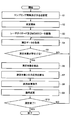
- FIG. 6 is a flowchart illustrating an example of the distance measurement process.
- the distance measurement process is started, for example, by the processor 41 of the computer 4 executing the distance measurement program stored in the memory 42.
- step S1 when the distance measurement process is started in response to a command input from the input device 43, in step S1, the computer 4 sets the setting data including the sampling interval and the azimuth angle to the measurement target 100. It is set in the measurement control unit 5 of 1.
- step S2 the computer 4 causes the measurement control unit 5 of the apparatus main body 1 to start measuring the distance at the distance measurement timing according to the set data.
- step S3 the computer 4 causes the measurement control unit 5 of the apparatus main body 1 to drive the laser diode 23 via the laser drive circuit 22 at the drive timing according to the set data. Further, in step S3, the computer 4 sends the measurement control unit 5 of the apparatus main body 1 to the piezoelectric element of the two-dimensional MEMS mirror 25 via the angle of view control unit 20 and the mirror drive circuit 24 at the drive timing according to the set data. To drive.
- step S4 the computer 4 acquires measurement data including a distance image and 3D data from the 3D measurement unit 6 of the apparatus main body 1.
- step S5 the computer 4 determines whether or not the measurement target 100 exists based on the 3D data of the measurement data and the distance image. If the determination result is No, the process returns to step S4, and the determination result is Yes. If so, the process proceeds to step S6.
- Whether or not the measurement target 100 exists within the scanning angle range scanned by the raster can be determined by a well-known method. For example, if the measurement target 100 is a person, the existence of the measurement target 100 may be determined by detecting the shape of the posture of the person, the skin color of the face of the person, and the like from the distance image.
- the generated 3D data or distance image is displayed on the display device 44 of the computer 4 and the user specifies (clicks) a desired position or range of the display screen with the input device 43 such as a mouse, the measurement target 100 exists. Then, a method of determining that the case may be adopted.
- step S6 since the measurement target 100 exists within the scanning angle range scanned by the raster, the computer 4 extracts, for example, the measurement target 100 detected from the distance image by a well-known method, and the extracted target data of the measurement target 100. Ask for.
- step S7 the computer 4 calculates the azimuth angle up to the measurement target 100 by a well-known method from, for example, the extracted target data and the light projection angle information of the 3D data, and stores it in the memory 42 as needed. ..
- step S8 the scanning angle range, the center angle of the scanning angle range, and the shift angle are set so that the measurement control unit 5 of the apparatus main body 1 has an azimuth angle up to the measurement target 100 included in the setting data from the computer 4. Calculate each set value of.
- the measurement control unit 5 of the apparatus main body 1 outputs the angle of view change instruction, the scanning angle range, the center angle of the scanning angle range, and the set values of the shift angle to the angle of view control unit 20. , Instructs to change the angle of view during dynamic control of the angle of view.
- step S9 the angle of view control unit 20 of the device main body 1 changes the angle of view according to the angle of view change instruction from the measurement control unit 5. Specifically, the angle of view control unit 20 outputs a correction offset amount, which will be described later, to the mirror drive circuit 24 together with the drive control signal to drive the two-dimensional MEMS mirror 25. The details of the angle of view change processing in steps S8 and S9 will be described later.
- the angle of view change process in steps S8 and S9 may be started by, for example, the processor forming the measurement control unit 5 and the angle of view control unit 20 executing the angle of view change program stored in the memory.
- the computer 4 may execute the angle of view change processing in steps S8 and S9.
- step S10 the computer 4 determines whether or not the distance measurement process has been completed. If the determination result is No, the process returns to step S4, and if the determination result is Yes, the process ends.
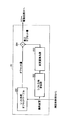
- FIG. 7 is a functional block diagram showing an example of the angle of view control unit in the first embodiment.
- the angle of view control unit 20 includes a shift angle offset table 201, a shift direction calculation unit 202, a change amount calculation unit 203, and an addition unit 204.
- the offset amount is corrected only in the shift direction from top to bottom.
- the angle of view control unit 20 calculates an offset amount with respect to the shift angle according to the shift direction with reference to the shift angle offset table 201 based on the angle of view change instruction from the measurement control unit 5, and supplies the offset amount to the addition unit 204.
- the shift direction calculation unit 202 calculates the shift direction based on the angle of view change instruction.
- the change amount calculation unit 203 refers to the offset correction table when the offset amount needs to be changed (in this example, from top to bottom) in the shift direction.
- the change amount calculation unit 203 calculates the change amount (offset correction amount) for the shift angle difference according to the shift direction for changing (or correcting) the offset amount from the offset correction table, and supplies the change amount to the addition unit 204. ..
- the shift angle difference indicates the angle difference between the center angles of the scanning angle range before and after the shift.
- the offset correction table is provided in, for example, the change amount calculation unit 203.
- the change amount calculation unit 203 does not refer to the offset correction table and does not output (or change) the change amount in the shift direction in which the offset amount does not need to be changed (in this example, from bottom to top). Outputs a quantity of zero (0)).
- the addition unit 204 adds the change amount to the offset amount when the change amount is not supplied from the change amount calculation unit 203, and adds the change amount to the offset amount when the change amount is supplied from the change amount calculation unit 203 to obtain the correction offset amount. Output.
- the angle of view control unit 20 outputs the correction offset amount from the addition unit 204 to the mirror drive circuit 24 together with the drive control signal to drive the two-dimensional MEMS mirror 25. That is, the angle of view control unit 20 causes the mirror drive circuit 24 to output a drive signal having a non-resonant drive waveform for driving the two-dimensional MEMS mirror 25 in the vertical direction.
- the mirror drive circuit 24 includes an adjustment circuit that generates a drive signal having a saw waveform with voltage adjustment or the like based on a correction offset amount from the angle of view control unit 20 and a drive control signal.
- such an adjustment circuit may be separately provided between the angle of view control unit 20 and the mirror drive circuit 24.
- the angle of view control unit 20 causes the mirror drive circuit 24 to output a drive signal having a resonance drive waveform for driving the two-dimensional MEMS mirror 25 in the horizontal direction, but the drive itself by such a drive signal is well known. Yes, the description is omitted.
- FIG. 8 is a diagram illustrating an example of the relationship between the shift angle and the offset amount.
- the vertical axis indicates the shift angle of the central angle of the scanning angle range in arbitrary units
- the horizontal axis indicates the offset voltage corresponding to the offset amount for offsetting the drive signal having the resonance drive waveform in arbitrary units.
- FIG. 8 shows an example in which the offset amount is corrected only in the case of the shift direction from top to bottom with reference to the shift direction from bottom to top according to the hysteresis characteristic of the piezoelectric element of the two-dimensional MEMS mirror 25.
- the resonance drive waveform is set to the offset voltage corresponding to the offset amount for shifting the center angle upward by d degrees. Is added to the drive signal having.
- the offset voltage corresponding to the offset amount for shifting the center angle downward by d degrees is resonantly driven. It is subtracted from the drive signal having a waveform.
- the shift direction from bottom to top is used as a reference according to the hysteresis characteristic of the piezoelectric element of the two-dimensional MEMS mirror 25, it corresponds to the offset amount only in the shift direction from top to bottom.
- Change the offset voltage In the example shown in FIG. 8, the offset voltage when the shift angle is set to d degree in the case of the reference shift direction from bottom to top is the reference voltage V0.
- the offset voltage when the shift angle is set to d degree in the shift direction from top to bottom is V0-Vd by adding the voltage -Vd corresponding to the change amount (offset correction amount). Change to.
- the center angle of the scanning angle range can be accurately shifted regardless of the shifting direction of the center angle of the scanning angle range.
- FIG. 9 is a flowchart illustrating an example of processing of the angle of view control unit in the first embodiment.
- FIG. 9 shows an example in which the offset amount is corrected only in the case of the shift direction from top to bottom with reference to the shift direction from bottom to top according to the piezoelectric element.
- the angle of view change process shown in FIG. 9 corresponds to the processes of steps S8 and S9 during the distance measurement process shown in FIG.
- the angle of view control unit 20 starts the angle of view change process in response to the angle of view change instruction from the measurement control unit 5.
- step S21 the angle of view control unit 20 calculates an offset amount with respect to the shift angle according to the shift direction by referring to, for example, the shift angle offset table 201 shown in FIG. 10, based on the angle of view change instruction, and causes the addition unit 204. Supply.
- step S22 the shift direction calculation unit 202 calculates the shift direction based on the angle of view change instruction.
- the change amount calculation unit 203 determines whether or not the offset amount needs to be changed in the shift direction (from top to bottom in this example). If the determination result in step S23 is No, the process proceeds to step S25, which will be described later.
- step S24 the change amount calculation unit 203 supplies the offset amount (constant) corresponding to FIG. 8 depending on the direction to the addition unit 204.
- step S25 the addition unit 204 adds the offset amount to the offset amount when the change amount is not supplied from the change amount calculation unit 203, and adds the change amount to the offset amount when the change amount is supplied from the change amount calculation unit 203. Output as a correction offset amount.
- the change amount calculation unit 203 refers to the offset correction table shown in FIG. 11 and changes the change amount with respect to the shift angle difference according to the shift direction. (Offset correction amount) is calculated and supplied to the addition unit 204.
- step S26 the angle of view control unit 20 outputs the correction offset amount together with the drive control signal to the mirror drive circuit 24 to drive the two-dimensional MEMS mirror 25. Specifically, the angle of view control unit 20 causes the mirror drive circuit 24 to output a drive signal having a non-resonant drive waveform for driving the two-dimensional MEMS mirror 25 in the vertical direction.
- step S26 the process returns to step S10 of the distance measurement process shown in FIG.
- steps S23 and S24 may be executed before the processes of steps S21 and S22. Further, the processes of steps S21 and S22 and the processes of steps S23 and S24 may be executed in parallel.
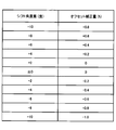
- FIG. 10 is a diagram showing an example of a shift angle offset table.
- the shift angle offset table 201 shown in FIG. 10 stores an output offset amount (%) with respect to a shift angle (degree) according to an input shift direction.
- the shift angle (degrees) shown in FIG. 10 indicates the shift angle from the state where the center angle of the scanning angle range is zero (0) degrees, and the shift direction from the bottom to the top is indicated by a positive (+) value from the top.
- the downward shift direction is indicated by a negative (-) value.
- the offset amount (%) is a value obtained by dividing the offset voltage corresponding to the offset amount by the maximum amplitude of the drive voltage having the non-resonant drive waveform.
- the shift angle corresponding to the matching shift direction may not be stored in the shift angle offset table 201 of FIG. obtain.
- the offset amount with respect to the shift angle according to the shift direction may be calculated by a well-known method such as approximation from the offset amount with respect to the stored shift direction.
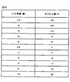
- FIG. 11 is a diagram showing an example of an offset correction table.
- the offset correction table shown in FIG. 11 stores an output offset correction amount (%) with respect to a shift angle difference (degree) according to an input shift direction.
- the shift angle difference (degrees) shown in FIG. 11 indicates the angle difference between the center angles of the scanning angle range before and after the shift as a positive (+) value in the shift direction from bottom to top, and from top to bottom.
- the shift direction of is indicated by a negative (-) value.
- the offset correction amount (%) is a value obtained by dividing the offset correction voltage corresponding to the offset correction amount by the maximum amplitude of the drive voltage having the non-resonant drive waveform.
- the change amount calculation unit 203 calculates the offset correction amount for the shift angle difference according to the shift direction
- the offset correction amount for the shift angle difference according to the shift direction may be calculated from the stored offset correction amount for the shift angle difference according to the shift direction by a well-known method such as approximation.
- FIG. 12 is a functional block diagram showing an example of the angle of view control unit in the second embodiment.
- the angle of view control unit 20 includes a shift angle offset table 201, a shift direction and shift angle difference calculation unit 211, a change amount calculation unit 212, and an addition unit 204.
- the shift angle offset table 201 includes a first shift angle offset table 201A shown in FIG. 13 and a second shift angle offset table 201B shown in FIG.
- the shift direction and shift angle difference calculation unit 211 of the angle of view control unit 20 calculates the shift direction and shift angle difference based on the angle of view change instruction from the measurement control unit 5.
- the angle of view control unit 20 calculates an offset amount with respect to the calculated shift angle according to the calculated shift direction with reference to the shift angle offset table 201, and supplies the offset amount to the addition unit 204.
- the angle of view control unit 20 selects and refers to the shift angle offset table 201A or the shift angle offset table 201B according to the calculated shift direction.
- the angle of view control unit 20 selects and refers to the first shift angle offset table 201A in the case of the shift direction from the bottom to the top, and the second shift angle control unit 20 in the case of the shift direction from the top to the bottom.
- the shift angle offset table 201B is selected and referenced.
- the shift direction and shift angle difference calculation unit 211 supplies the calculated shift direction and shift angle difference to the change amount calculation unit 212.
- the shift angle difference indicates the angle difference between the center angles of the scanning angle range before and after the shift.
- the change amount calculation unit 212 calculates an offset correction amount for the calculated shift angle difference according to the calculated shift direction by referring to the offset correction table shown in FIG. 15, and supplies the offset correction amount to the addition unit 204.
- the addition unit 204 adds the change amount to the offset amount when the change amount (offset correction amount) is not supplied from the change amount calculation unit 212, and adds the change amount to the offset amount when the change amount is supplied from the change amount calculation unit 212. , Output as a correction offset amount.
- the shift angle offset tables 201A and 201B shown in FIGS. 13 and 14 store an output offset amount (%) with respect to a shift angle (degree) according to an input shift direction.
- the shift angle (degrees) shown in FIGS. 13 and 14 indicates the shift angle from the state where the center angle of the scanning angle range is zero (0) degrees, and the shift direction from bottom to top is indicated by a positive (+) value.
- the shift direction from top to bottom is indicated by a negative (-) value.
- the shift direction from bottom to top is an example of a first shift direction
- the shift direction from top to bottom is an example of a second shift direction opposite to the first shift direction.
- the offset amount (%) is a value obtained by dividing the offset voltage corresponding to the offset amount by the maximum amplitude of the drive voltage having the non-resonant drive waveform.
- the matching shift angle may not be stored in the shift angle offset tables 201A and 201B of FIGS. 13 or 14. It can happen.
- the offset amount with respect to the shift angle according to the shift direction may be calculated by a well-known method such as approximation from the offset amount with respect to the stored shift direction.
- FIG. 15 is a diagram showing an example of an offset correction table.
- the offset correction table shown in FIG. 15 stores an output offset correction amount (%) with respect to an input shift direction and a shift angle difference (degrees).
- the shift angle difference (degrees) shown in FIG. 15 indicates the angle difference between the center angles of the scanning angle range before and after the shift as a positive (+) value in the shift direction from bottom to top, and from top to bottom.
- the shift direction of is indicated by a negative (-) value.
- the offset correction amount (%) is a value obtained by dividing the offset correction voltage corresponding to the offset correction amount by the maximum amplitude of the drive voltage having the non-resonant drive waveform.
- the change amount calculation unit 212 calculates the offset correction amount for the shift angle difference according to the shift direction
- the offset correction amount for the shift angle difference according to the shift direction may be calculated from the stored offset correction amount for the shift angle difference according to the shift direction by a well-known method such as approximation.
- the angle of view control unit 20 outputs the correction offset amount from the addition unit 204 to the mirror drive circuit 24 together with the drive control signal to drive the two-dimensional MEMS mirror 25. That is, the angle of view control unit 20 causes the mirror drive circuit 24 to output a drive signal having a non-resonant drive waveform for driving the two-dimensional MEMS mirror 25 in the vertical direction.
- the mirror drive circuit 24 includes an adjustment circuit that generates a drive signal having a saw waveform with voltage adjustment or the like based on a correction offset amount from the angle of view control unit 20 and a drive control signal.
- such an adjustment circuit may be separately provided between the angle of view control unit 20 and the mirror drive circuit 24.
- FIG. 16 is a flowchart illustrating an example of processing of the angle of view control unit in the second embodiment.
- the offset amount is calculated using the first shift angle offset table 201A shown in FIG.
- the offset amount is calculated using the second shift angle offset table 201B shown in FIG. That is, in this example, the offset amount differs between the case of the shift direction from the bottom to the top and the case of the shift direction from the top to the bottom.
- the angle of view change process shown in FIG. 16 corresponds to the processes of steps S8 and S9 during the distance measurement process shown in FIG.
- the angle of view control unit 20 starts the angle of view change process in response to the angle of view change instruction from the measurement control unit 5.
- the shift direction and shift angle difference calculation unit 211 calculates the shift direction and shift angle based on the angle of view change instruction and supplies the change amount calculation unit 212.
- the angle of view control unit 20 selects the first shift angle offset table 201A shown in FIG. 13 or the second shift angle offset table 201B shown in FIG. 14 according to the calculated shift direction. Specifically, the first shift angle offset table 201A is selected in the shift direction from bottom to top, and the second shift angle offset table 201B is selected in the shift direction from top to bottom.
- the angle of view control unit 20 refers to the selected shift angle offset table 201A or 201B, calculates an offset amount with respect to the calculated shift angle according to the calculated shift direction, and supplies the offset amount to the addition unit 204.
- the change amount calculation unit 212 refers to, for example, the offset correction table shown in FIG. Specifically, the change amount calculation unit 212 refers to the offset correction table and calculates the change amount (offset correction amount) for the shift angle difference according to the calculated shift direction for changing the offset amount.
- step S35 the change amount calculation unit 212 supplies the calculated change amount to the addition unit 204.
- step S36 the addition unit 204 adds the offset amount to the offset amount when the change amount is not supplied from the change amount calculation unit 212, and adds the change amount to the offset amount when the change amount is supplied from the change amount calculation unit 212. Output as a correction offset amount.
- step S37 the angle of view control unit 20 outputs the correction offset amount together with the drive control signal to the mirror drive circuit 24 to drive the two-dimensional MEMS mirror 25. Specifically, the angle of view control unit 20 causes the mirror drive circuit 24 to output a drive signal having a non-resonant drive waveform for driving the two-dimensional MEMS mirror 25 in the vertical direction.
- steps S34 and S35 may be executed before the processes of steps S32 and S33. Further, the processes of steps S32 and S33 and the processes of steps S34 and S35 may be executed in parallel.
- FIG. 17 is a diagram for explaining the angle of view switching section.
- the vertical axis indicates the voltage of the drive signal having the non-resonant drive waveform in an arbitrary unit
- the horizontal axis indicates the time in an arbitrary unit.
- the angle-of-view switching section for controlling the angle of view is a folding section between the folding of the non-resonant drive waveform of the driving signal after the end of the emission of the laser beam and the before the start of the emission of the laser light.
- the angle of view control unit 20 changes the offset amount in this angle of view switching section excluding the light emitting section of the laser diode 23.
- the angle of view control unit 20 outputs the correction offset amount from the addition unit 204 to the mirror drive circuit 24 in the angle of view switching section.
- the measurement control unit 5 supplies the angle of view change instruction and the angle of view parameter to the angle of view control unit 20 based on the sampling interval included in the setting data from the computer 4, and in the above angle of view switching section.
- the correction offset amount from the addition unit 204 is output to the mirror drive circuit 24.
- the two-dimensional MEMS mirror 25 is a piezoelectric element that is driven by a drive signal having a non-resonant drive waveform along one axis that controls the angle of view to control the angle of view of scanning by laser light.
- the driving unit of the two-dimensional MEMS mirror 25 is not limited to the piezoelectric element, and may be a driving element other than the piezoelectric element, for example, having the same hysteresis characteristics as the piezoelectric element.
- the distance measuring device can be applied to scoring support systems, in-vehicle systems, etc.
- An example of a scoring support system supports scoring, for example, gymnastics performance based on the output of a distance measuring device.
- the measurement target 100 is a gymnast
- scoring can be performed by, for example, the computer 4 shown in FIG. 2 executing a scoring program.
- the computer 4 may acquire the skeleton information of the gymnast by a well-known method based on the 3D data and the distance image from the 3D measuring unit 6. Since the gymnast's skeletal information includes the three-dimensional positions of each joint of the gymnast in each frame, it is possible to recognize the gymnastic performance technique from the skeletal information and score the gymnastic performance from the degree of completion of the technique. ..
- the movement speed of the gymnast is fast, and it is necessary to control the angle of view of the distance measuring device according to the position of the gymnast.
- the center angle can be controlled equally regardless of the shift direction, so that the gymnast can be controlled in the vertical direction.
- the movement speed of the gymnast is fast, it is possible to suppress a decrease in the measurement accuracy of the distance measuring device, and by using the output of such a distance measuring device, it is possible to perform the scoring of the gymnastics performance with high accuracy. It is possible to improve the reliability of the scoring support system.
- An example of an in-vehicle system recognizes, for example, the position and type of a measurement target 100 in front of a vehicle based on the output of a distance measuring device.
- the type of the measurement target 100 includes a pedestrian, another vehicle, and the like, and the measurement target 100 can be recognized by, for example, the computer 4 shown in FIG. 2 executing a recognition program.
- the computer 4 may acquire the shape information of the measurement target 100 by a well-known method based on the 3D data and the distance image from the measurement control unit 5. Since the shape information of the measurement target 100 includes the three-dimensional positions of each part of the measurement target 100 in each frame, the position, type, etc.
- the distance measuring device When the distance measuring device is applied to the in-vehicle system, the distance measuring device itself moves together with the vehicle mounted on the vehicle, so that the relative moving speed of the measurement target 100 may be high. However, even for the measurement target 100 having a high relative moving speed, according to each of the above embodiments, it is possible to suppress a decrease in the measurement accuracy of the distance measuring device, so that the position, type, etc. of the measurement target 100 can be determined. It can be recognized with high accuracy and the reliability of the in-vehicle system can be improved.
Landscapes
- Engineering & Computer Science (AREA)
- Physics & Mathematics (AREA)
- Computer Networks & Wireless Communication (AREA)
- General Physics & Mathematics (AREA)
- Radar, Positioning & Navigation (AREA)
- Remote Sensing (AREA)
- Electromagnetism (AREA)
- Computer Hardware Design (AREA)
- Microelectronics & Electronic Packaging (AREA)
- Optical Radar Systems And Details Thereof (AREA)
- Mechanical Optical Scanning Systems (AREA)
Priority Applications (3)
| Application Number | Priority Date | Filing Date | Title |
|---|---|---|---|
| PCT/JP2020/016111 WO2021205647A1 (ja) | 2020-04-10 | 2020-04-10 | 距離測定装置、画角制御方法、及びプログラム |
| JP2022513831A JPWO2021205647A1 (https=) | 2020-04-10 | 2020-04-10 | |
| US17/896,257 US20220411258A1 (en) | 2020-04-10 | 2022-08-26 | Distance measurement apparatus, angle-of-view control method, and computer-readable recording medium storing program |
Applications Claiming Priority (1)
| Application Number | Priority Date | Filing Date | Title |
|---|---|---|---|
| PCT/JP2020/016111 WO2021205647A1 (ja) | 2020-04-10 | 2020-04-10 | 距離測定装置、画角制御方法、及びプログラム |
Related Child Applications (1)
| Application Number | Title | Priority Date | Filing Date |
|---|---|---|---|
| US17/896,257 Continuation US20220411258A1 (en) | 2020-04-10 | 2022-08-26 | Distance measurement apparatus, angle-of-view control method, and computer-readable recording medium storing program |
Publications (1)
| Publication Number | Publication Date |
|---|---|
| WO2021205647A1 true WO2021205647A1 (ja) | 2021-10-14 |
Family
ID=78022510
Family Applications (1)
| Application Number | Title | Priority Date | Filing Date |
|---|---|---|---|
| PCT/JP2020/016111 Ceased WO2021205647A1 (ja) | 2020-04-10 | 2020-04-10 | 距離測定装置、画角制御方法、及びプログラム |
Country Status (3)
| Country | Link |
|---|---|
| US (1) | US20220411258A1 (https=) |
| JP (1) | JPWO2021205647A1 (https=) |
| WO (1) | WO2021205647A1 (https=) |
Cited By (1)
| Publication number | Priority date | Publication date | Assignee | Title |
|---|---|---|---|---|
| JPWO2023120375A1 (https=) * | 2021-12-21 | 2023-06-29 |
Citations (8)
| Publication number | Priority date | Publication date | Assignee | Title |
|---|---|---|---|---|
| US20100039424A1 (en) * | 2008-08-14 | 2010-02-18 | Qualcomm Mems Technologies, Inc. | Method of reducing offset voltage in a microelectromechanical device |
| JP2012002642A (ja) * | 2010-06-16 | 2012-01-05 | Pulstec Industrial Co Ltd | 3次元形状測定装置 |
| JP2012124880A (ja) * | 2010-11-19 | 2012-06-28 | Ricoh Co Ltd | 画像投影装置、メモリ制御装置、レーザープロジェクタ、メモリアクセス方法 |
| JP2014020963A (ja) * | 2012-07-19 | 2014-02-03 | Fujitsu Ltd | 距離測定装置、発光タイミング制御装置及びプログラム |
| CN107450178A (zh) * | 2017-09-06 | 2017-12-08 | 北京航天长征飞行器研究所 | 一种二维mems微镜驱动控制系统和方法 |
| JP2018063228A (ja) * | 2016-10-14 | 2018-04-19 | 富士通株式会社 | 距離測定装置、距離測定方法、及び距離測定プログラム |
| JP2018101151A (ja) * | 2018-03-02 | 2018-06-28 | パイオニア株式会社 | 表示制御装置 |
| JP2019113457A (ja) * | 2017-12-25 | 2019-07-11 | パイオニア株式会社 | 走査装置及び測距装置 |
Family Cites Families (3)
| Publication number | Priority date | Publication date | Assignee | Title |
|---|---|---|---|---|
| JP2017211432A (ja) * | 2016-05-23 | 2017-11-30 | スタンレー電気株式会社 | 映像投射システム |
| JP2020034386A (ja) * | 2018-08-29 | 2020-03-05 | パイオニア株式会社 | 走査装置及び測距装置 |
| WO2021245809A1 (ja) * | 2020-06-02 | 2021-12-09 | 富士通株式会社 | 距離測定装置、ミラー制御方法、及びプログラム |
-
2020
- 2020-04-10 JP JP2022513831A patent/JPWO2021205647A1/ja active Pending
- 2020-04-10 WO PCT/JP2020/016111 patent/WO2021205647A1/ja not_active Ceased
-
2022
- 2022-08-26 US US17/896,257 patent/US20220411258A1/en not_active Abandoned
Patent Citations (8)
| Publication number | Priority date | Publication date | Assignee | Title |
|---|---|---|---|---|
| US20100039424A1 (en) * | 2008-08-14 | 2010-02-18 | Qualcomm Mems Technologies, Inc. | Method of reducing offset voltage in a microelectromechanical device |
| JP2012002642A (ja) * | 2010-06-16 | 2012-01-05 | Pulstec Industrial Co Ltd | 3次元形状測定装置 |
| JP2012124880A (ja) * | 2010-11-19 | 2012-06-28 | Ricoh Co Ltd | 画像投影装置、メモリ制御装置、レーザープロジェクタ、メモリアクセス方法 |
| JP2014020963A (ja) * | 2012-07-19 | 2014-02-03 | Fujitsu Ltd | 距離測定装置、発光タイミング制御装置及びプログラム |
| JP2018063228A (ja) * | 2016-10-14 | 2018-04-19 | 富士通株式会社 | 距離測定装置、距離測定方法、及び距離測定プログラム |
| CN107450178A (zh) * | 2017-09-06 | 2017-12-08 | 北京航天长征飞行器研究所 | 一种二维mems微镜驱动控制系统和方法 |
| JP2019113457A (ja) * | 2017-12-25 | 2019-07-11 | パイオニア株式会社 | 走査装置及び測距装置 |
| JP2018101151A (ja) * | 2018-03-02 | 2018-06-28 | パイオニア株式会社 | 表示制御装置 |
Cited By (3)
| Publication number | Priority date | Publication date | Assignee | Title |
|---|---|---|---|---|
| JPWO2023120375A1 (https=) * | 2021-12-21 | 2023-06-29 | ||
| WO2023120375A1 (ja) * | 2021-12-21 | 2023-06-29 | パイオニア株式会社 | 光学装置 |
| JP2025083459A (ja) * | 2021-12-21 | 2025-05-30 | パイオニア株式会社 | 光学装置 |
Also Published As
| Publication number | Publication date |
|---|---|
| JPWO2021205647A1 (https=) | 2021-10-14 |
| US20220411258A1 (en) | 2022-12-29 |
Similar Documents
| Publication | Publication Date | Title |
|---|---|---|
| US11523095B2 (en) | Mems mirror-based extended reality projection with eye-tracking | |
| KR102385030B1 (ko) | 해상도가 조정가능한 깊이 매핑 장치 및 방법 | |
| US20230051900A1 (en) | Distance measurement apparatus, mirror control method, and computer-readable recording medium storing program | |
| EP1903304B1 (en) | Position measuring system, position measuring method and position measuring program | |
| JP6753107B2 (ja) | 距離測定装置、距離測定方法及びプログラム | |
| JP6862751B2 (ja) | 距離測定装置、距離測定方法及びプログラム | |
| CN111788495B (zh) | 光检测装置、光检测方法以及激光雷达装置 | |
| JP2019203822A (ja) | 測量装置 | |
| US11828881B2 (en) | Steered LIDAR system with arrayed receiver | |
| US11747476B2 (en) | Dynamically interlaced laser beam scanning 3D depth sensing system and method | |
| US11796643B2 (en) | Adaptive LIDAR scanning methods | |
| US20220206251A1 (en) | Mirror control device, mirror control method, and storage medium | |
| CN112799080A (zh) | 深度感测装置及方法 | |
| US20220411258A1 (en) | Distance measurement apparatus, angle-of-view control method, and computer-readable recording medium storing program | |
| US11460297B2 (en) | Measurement apparatus and control method of measurement apparatus | |
| CN117629059A (zh) | 具有扫描式绝对测距仪的测量仪器 | |
| US12493121B2 (en) | High resolution lidar scanning | |
| WO2021032298A1 (en) | High resolution optical depth scanner | |
| US20150185321A1 (en) | Image Display Device | |
| JP7742459B2 (ja) | 情報処理装置、情報処理方法、およびプログラム | |
| JP7183017B2 (ja) | 測量装置及び写真測量方法 | |
| JP2011180450A (ja) | 光走査装置及びそれを備えた画像表示装置 | |
| CN117631263A (zh) | 微机电系统的扫描轴的快速李萨如锁定控制和同步 | |
| JP2014123170A (ja) | 位置判定装置及び位置判定方法 | |
| EP2811377B1 (en) | Manipulation input device, manipulation input system, and manipulation input method |
Legal Events
| Date | Code | Title | Description |
|---|---|---|---|
| 121 | Ep: the epo has been informed by wipo that ep was designated in this application |
Ref document number: 20930587 Country of ref document: EP Kind code of ref document: A1 |
|
| ENP | Entry into the national phase |
Ref document number: 2022513831 Country of ref document: JP Kind code of ref document: A |
|
| NENP | Non-entry into the national phase |
Ref country code: DE |
|
| 122 | Ep: pct application non-entry in european phase |
Ref document number: 20930587 Country of ref document: EP Kind code of ref document: A1 |