WO2021200653A1 - 制御装置 - Google Patents
制御装置 Download PDFInfo
- Publication number
- WO2021200653A1 WO2021200653A1 PCT/JP2021/012860 JP2021012860W WO2021200653A1 WO 2021200653 A1 WO2021200653 A1 WO 2021200653A1 JP 2021012860 W JP2021012860 W JP 2021012860W WO 2021200653 A1 WO2021200653 A1 WO 2021200653A1
- Authority
- WO
- WIPO (PCT)
- Prior art keywords
- setting
- work
- machine tool
- unit
- control unit
- Prior art date
- Legal status (The legal status is an assumption and is not a legal conclusion. Google has not performed a legal analysis and makes no representation as to the accuracy of the status listed.)
- Ceased
Links
Images





Classifications
-
- G—PHYSICS
- G05—CONTROLLING; REGULATING
- G05B—CONTROL OR REGULATING SYSTEMS IN GENERAL; FUNCTIONAL ELEMENTS OF SUCH SYSTEMS; MONITORING OR TESTING ARRANGEMENTS FOR SUCH SYSTEMS OR ELEMENTS
- G05B19/00—Program-control systems
- G05B19/02—Program-control systems electric
- G05B19/18—Numerical control [NC], i.e. automatically operating machines, in particular machine tools, e.g. in a manufacturing environment, so as to execute positioning, movement or co-ordinated operations by means of program data in numerical form
- G05B19/409—Numerical control [NC], i.e. automatically operating machines, in particular machine tools, e.g. in a manufacturing environment, so as to execute positioning, movement or co-ordinated operations by means of program data in numerical form characterised by using manual data input [MDI] or by using control panel, e.g. controlling functions with the panel; characterised by control panel details or by setting parameters
-
- G—PHYSICS
- G05—CONTROLLING; REGULATING
- G05B—CONTROL OR REGULATING SYSTEMS IN GENERAL; FUNCTIONAL ELEMENTS OF SUCH SYSTEMS; MONITORING OR TESTING ARRANGEMENTS FOR SUCH SYSTEMS OR ELEMENTS
- G05B19/00—Program-control systems
- G05B19/02—Program-control systems electric
- G05B19/18—Numerical control [NC], i.e. automatically operating machines, in particular machine tools, e.g. in a manufacturing environment, so as to execute positioning, movement or co-ordinated operations by means of program data in numerical form
- G05B19/4093—Numerical control [NC], i.e. automatically operating machines, in particular machine tools, e.g. in a manufacturing environment, so as to execute positioning, movement or co-ordinated operations by means of program data in numerical form characterised by part programming, e.g. entry of geometrical information as taken from a technical drawing, combining this with machining and material information to obtain control information, named part program, for the NC machine
- G05B19/40937—Numerical control [NC], i.e. automatically operating machines, in particular machine tools, e.g. in a manufacturing environment, so as to execute positioning, movement or co-ordinated operations by means of program data in numerical form characterised by part programming, e.g. entry of geometrical information as taken from a technical drawing, combining this with machining and material information to obtain control information, named part program, for the NC machine concerning programming of machining or material parameters, pocket machining
-
- G—PHYSICS
- G05—CONTROLLING; REGULATING
- G05B—CONTROL OR REGULATING SYSTEMS IN GENERAL; FUNCTIONAL ELEMENTS OF SUCH SYSTEMS; MONITORING OR TESTING ARRANGEMENTS FOR SUCH SYSTEMS OR ELEMENTS
- G05B2219/00—Program-control systems
- G05B2219/30—Nc systems
- G05B2219/32—Operator till task planning
- G05B2219/32128—Gui graphical user interface
-
- G—PHYSICS
- G05—CONTROLLING; REGULATING
- G05B—CONTROL OR REGULATING SYSTEMS IN GENERAL; FUNCTIONAL ELEMENTS OF SUCH SYSTEMS; MONITORING OR TESTING ARRANGEMENTS FOR SUCH SYSTEMS OR ELEMENTS
- G05B2219/00—Program-control systems
- G05B2219/30—Nc systems
- G05B2219/35—Nc in input of data, input till input file format
- G05B2219/35439—Keys or buttons
-
- G—PHYSICS
- G05—CONTROLLING; REGULATING
- G05B—CONTROL OR REGULATING SYSTEMS IN GENERAL; FUNCTIONAL ELEMENTS OF SUCH SYSTEMS; MONITORING OR TESTING ARRANGEMENTS FOR SUCH SYSTEMS OR ELEMENTS
- G05B2219/00—Program-control systems
- G05B2219/30—Nc systems
- G05B2219/35—Nc in input of data, input till input file format
- G05B2219/35519—Machining data and tool data
-
- G—PHYSICS
- G05—CONTROLLING; REGULATING
- G05B—CONTROL OR REGULATING SYSTEMS IN GENERAL; FUNCTIONAL ELEMENTS OF SUCH SYSTEMS; MONITORING OR TESTING ARRANGEMENTS FOR SUCH SYSTEMS OR ELEMENTS
- G05B2219/00—Program-control systems
- G05B2219/30—Nc systems
- G05B2219/36—Nc in input of data, input key till input tape
- G05B2219/36168—Touchscreen
Definitions
- the setup work for the machine tool is performed by setting a plurality of work items by performing a plurality of screen transitions.
- the machining mode of the desired machining is selected on the machining selection screen, the screen for setting the selected machining form is displayed in a preset order, and the required data required for the machining form is input in order. Therefore, a technique for automatically creating a desired machining program is known. For example, see Patent Document 1.
- One aspect of the control device of the present disclosure is a plurality of work items included in the setup work for the next machining in the machine tool based on the machine configuration including at least one of the number of axes and the number of systems in the machine tool to be set.
- a mandatory setting or an optional setting depending on the extraction unit that extracts each of the above as a required setting or an optional setting, and the operation content in the setup work for the machine tool from the completion of the latest machining by the machine tool to the present time.
- the machine tool has a determination unit that dynamically determines whether each of the extracted plurality of work items corresponds to either a required setting or an optional setting, and an incomplete or unupdated required setting. It is provided with an operation control unit that does not allow the machining operation of the above.
- the work status can be easily confirmed without remembering what work the worker has to do.
- FIG. 1 is a functional block diagram showing an example of a functional configuration of a control system according to an embodiment.
- the control system 1 includes a machine tool 10 and a control device 20.
- the machine tool 10 and the control device 20 may be directly connected to each other via a connection interface (not shown).
- the machine tool 10 and the control device 20 may be connected to each other via a network such as a LAN (Local Area Network).
- the machine tool 10 and the control device 20 may include a communication unit (not shown) for communicating with each other by such a connection.
- the control device 20 may be included in the machine tool 10.
- the machine tool 10 is a machine tool known to those skilled in the art, and operates based on an operation command of the control device 20.
- the machine tool 10 is a tool management table that manages all tools attached to the spindle (not shown) of the machine tool 10 in a storage unit (not shown) such as an HDD (Hard Disk Drive) included in the machine tool 10. (Not shown) may be stored.
- the control device 20 described later acquires the tool name, tool diameter, tool length, etc. from the tool management table (not shown) of the machine tool 10 based on the tool number or the like set in the machining program at the time of setup work. May be good.
- the control device 20 is a numerical control device known to those skilled in the art.
- the control device 20 generates an operation command based on an instruction from a worker received via an input device (not shown) such as a touch panel included in the control device 20 or a processing program to be executed, and generates an operation command. It is transmitted to the machine tool 10. As a result, the control device 20 controls the operation of the machine tool 10.
- the control device 20 includes a control unit 210, a display unit 220, and a storage unit 230. Further, the control unit 210 includes a machining completion detection unit 211, an operation detection unit 212, an extraction unit 213, a determination unit 214, a display control unit 215, an operation control unit 216, and a notification unit 217. In addition, the storage unit 230 has a work item table 231.
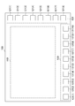
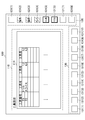
- the display unit 220 is a display device such as an LCD (Liquid Crystal Display), and has a touch panel (not shown) arranged in front of the display device. As shown in FIG. 2, in the case of setup work, the display unit 220 includes work items “creation / editing of machining program” and “machining program” included in the setup work based on control instructions from display control unit 215, which will be described later. Display the screen 100 including the setting screens of "selection of", “measurement and setting of workpiece", “setting of tool”, and “setting of custom macro variable”.
- each setting of the work items "creation / editing of machining program”, “selection of machining program”, “measurement and setting of workpiece”, “tool setting”, and “setting of custom macro variable” is shown, for example. It may be performed based on the input operation of the worker through the touch panel.
- the screen 100 shown in FIG. 2 has, for example, an area (hereinafter, also referred to as “setting display area 110”) in which a setting screen for a work item selected by an operator is displayed.
- the screen 100 also includes an area for displaying soft keys 121 (1) -121 (m) in a vertical row (hereinafter, also referred to as “vertical key display area 120”) and soft keys 131 (1) -131 (n).
- m and n are positive integers.
- the soft keys 121 (1) to 121 (m) will be described later with a function for transitioning a setting screen for each work item such as "creation / editing of a machining program" for setup work displayed in the setting display area 110. It is assigned by the display control unit 215. Further, the soft keys 131 (1) to 131 (n) are assigned screen operation functions corresponding to each setting screen by the display control unit 215, which will be described later.
- the soft keys 121 (1) -121 (m) may be assigned a screen operation function, and the soft keys 131 (1) -131 (n) have a function of transitioning the setting screen for each work item. May be assigned.
- soft key 131 the soft key 131
- the storage unit 230 is a ROM (Read Only Memory), an HDD, or the like, and may store the work item table 231 together with various control programs.
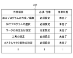
- FIG. 3 is a diagram showing an example of the work item table 231.
- the work item table 231 includes, for example, "work items” in the setup work of the next machining in the machine tool 10 from the completion of the latest machining in the machine tool 10 to the present time.
- the work item table 231 includes "required / optional” and "work state” corresponding to each work item.
- the work item required for the setup work of the next machining in the machine tool 10 from the completion of the latest machining to the present time is set.
- "creation / editing of machining program” selection of machining program
- “measurement and setting of workpiece” “tool setting”, “setting of custom macro variable”, etc. are set as work items. You may.
- “Required / Arbitrary” in the work item table 231 is a work item in which each setting of the work item is indispensable based on the extraction result of the extraction unit 213 described later or the judgment result of the determination unit 214 described later (hereinafter, ““Required / Arbitrary”).
- Work items hereinafter, also referred to as "arbitrary settings” whose settings are arbitrary (also referred to as “essential settings”) are stored.
- the "work status" in the work item table 231 is stored as either incomplete or unupdated, or completed or unupdated, based on the determination result of the determination unit 214 described later.
- the control unit 210 includes a CPU (Central Processing Unit), a ROM, a RAM, a CMOS (Complementary Metal-Oxide-Semiconductor) memory, and the like, which are known to those skilled in the art, which are configured to be able to communicate with each other via a bus. belongs to.
- the CPU is a processor that controls the control device 20 as a whole. The CPU reads out the system program and the application program stored in the ROM via the bus, and controls the entire control device 20 according to the system program and the application program. As a result, as shown in FIG.
- control unit 210 functions as a machining completion detection unit 211, an operation detection unit 212, an extraction unit 213, a determination unit 214, a display control unit 215, an operation control unit 216, and a notification unit 217. Is configured to realize. Various data such as temporary calculation data and display data are stored in the RAM. Further, the CMOS memory is backed up by a battery (not shown), and is configured as a non-volatile memory in which the storage state is maintained even when the power of the control device 20 is turned off.
- the machining completion detection unit 211 detects, for example, that the machining of one workpiece in the machine tool 10 has been completed.
- the operation detection unit 212 detects operation contents such as an operation by the worker on the machine tool 10 of the worker and an input operation of the worker via the touch panel (not shown) of the display unit 220.
- the operation detection unit 212 is, for example, an operation related to the setup work of the next processing in the machine tool 10 from the time when the processing completion detection unit 211 detects the completion of the latest processing to the present time (for example,). Operation to change the selection of the main program of each system, operation to change the main program of each system, operation to change the tool number (T number) or tool offset value of each system, operation to change the work coordinates, and custom macro variables. Detect the operation contents of).
- the extraction unit 213 sets each of a plurality of work items included in the setup work for the next machining in the machine tool 10 based on the machine configuration including at least one of the number of axes and the number of systems in the machine tool 10 to be set. Is a required setting or a setting is extracted as an optional setting.
- the extraction unit 213 updates "required / optional" in the work item table 231 based on the extraction result.
- the extraction unit 213 is, for example, a machine such as the number of axes, the number of systems, and the presence / absence of a pallet changer from the machine tool 10 to the machine tool 10 when the processing completion detection unit 211 detects the completion of the latest processing. Acquire configuration information indicating the configuration.
- the extraction unit 213 When the machine tool 10 has a pallet changer in the acquired configuration information, the extraction unit 213 does not need to measure and set the work coordinates for each machining. Therefore, the work item "measurement and setting of the work” is set to "arbitrary setting". It may be extracted as. On the other hand, when the machine tool 10 does not have a pallet changer, the extraction unit 213 extracts the work item "work measurement and setting” as "essential setting” because it is necessary to measure and set the work coordinates for each machining. You may. Further, since the extraction unit 213 needs to set the work coordinates for the number of axes based on the number of axes of the acquired configuration information, the work item "measurement and setting of the work” is extracted as "essential setting". You may.
- the determination unit 214 extracts each work item of the setup work as an essential setting or an optional setting by the extraction unit 213, and then sets it as an essential setting or an optional setting according to the operation content in the setup work detected by the operation detection unit 212. It is dynamically determined whether each of the extracted work items of the setup work corresponds to either the required setting or the optional setting. Specifically, when the operation content detected by the operation detection unit 212 changes the selection of the main program of each system, the determination unit 214 needs to set the tool offset with respect to the setting at the latest machining end time.
- the determination unit 214 needs to change the custom macro variable with respect to the setting at the latest processing end time, so the determination unit 214 is extracted as an arbitrary setting by the extraction unit 213. Even if the work item "custom macro variable setting” is determined to be “required setting”, “required / optional” in the work item table 231 is dynamically changed.
- the determination unit 214 may not need to change the tool offset with respect to the setting at the latest machining end time. Therefore, even if the work item "tool setting" is extracted as a required setting by the extraction unit 213, the work item “tool setting” is determined to be “arbitrary setting", and the "required / optional” of the work item table 231 is dynamically changed. Further, when the main program of each system is changed, the determination unit 214 may not need to change the custom macro variable with respect to the setting at the latest processing end time, so the determination unit 214 extracts it as an essential setting by the extraction unit 213. Even if it is done, the work item "custom macro variable setting” is determined to be “arbitrary setting”, and the "required / optional” of the work item table 231 is dynamically changed.
- the determination unit 214 sets the machining program for the setting at the latest machining end time. Therefore, even if the work item "Create / Edit Machining Program" is determined to be “Required” even if it is extracted as an optional setting by the extraction unit 213, "Required / Optional” in the work item table 231 is set. Change dynamically.
- the determination unit 214 needs to change the selection of the machining program with respect to the setting at the latest machining end time, and thus the extraction unit 214. Even if it is extracted as an optional setting by 213, the work item "selection of machining program” may be determined as “essential setting", and "essential / optional” in the work item table 231 may be dynamically changed.
- the determination unit 214 extracts the processing program because it may not be necessary to change the processing program with respect to the setting at the latest processing end time. Even if the work item "creation / edit of the machining program" is determined to be "arbitrary setting" even if it is extracted as a required setting by the part 213, the "required / optional" of the work item table 231 is dynamically changed. This means that, for example, when the work coordinates are changed for fine adjustment, it is not necessary to modify the machining program. Therefore, the determination unit 214 changes the work item "creation / editing of the machining program" in the work item table 231 to "arbitrary setting".
- the determination unit 214 needs to change the processing program with respect to the setting at the latest processing end time, so that the extraction unit 214 Even if it is extracted as an optional setting by 213, the work item "creation / editing of machining program" is determined as “essential setting", and "essential / optional” in the work item table 231 is dynamically changed.
- the determination unit 214 needs to change the selection of the processing program with respect to the setting at the latest processing end time, so even if the determination unit 214 is extracted as an arbitrary setting by the extraction unit 213.
- the work item "selection of machining program” may be determined as “essential setting", and "essential / optional” in the work item table 231 may be dynamically changed.
- the operation detection unit 212 detects an operation such as a worker pressing the "save” soft key 131, and the machining program is created or edited. If so, the determination unit 214 may update the "work state" of the work item “creation / edit of the machining program" in the work item table 231 from the incomplete or unupdated state to the completed or updated state. Further, in the work of the work item "selection of machining program", the operation detection unit 212 detects an operation such as the soft key 131 of "setting" being pressed by the worker, and the main program is set in the control device 20.
- the determination unit 214 may update the "work state" of the work item "selection of machining program" in the work item table 231 from the incomplete or unupdated state to the completed or updated state. Further, in the work of the work item "measurement and setting of the work", the operation detection unit 212 detects an operation such as the soft key 131 of the "setting” being pressed by the worker, and the work coordinates are set in the control device 20. In this case, the determination unit 214 may update the "work state” of the work item “work measurement and setting” in the work item table 231 from the incomplete or unupdated state to the completed or updated state.
- the operation detection unit 212 detects an operation such as the soft key 131 of "setting” being pressed by the worker and the tool is set in the control device 20.
- the determination unit 214 may update the "work state" of the work item “tool setting” in the work item table 231 from the incomplete or unupdated state to the completed or updated state.
- the operation detection unit 212 detects an operation such as the soft key 131 of "setting” being pressed by the worker, and the custom macro variable is set in the control device 20. If so, the determination unit 214 may update the "work state” of the work item "custom macro variable setting” in the work item table 231 from the incomplete or unupdated state to the completed or updated state.
- ⁇ Display control unit 215 sets each of the work items "creation / editing of machining program”, “selection of machining program”, “measurement and setting of workpiece”, “setting of tool”, and “setting of custom macro variable”. Based on the determination result of the determination unit 214, either the required setting or the optional setting is dynamically changed so as to be discriminable and displayed on the display unit 220.
- the display control unit 215 has, for example, the work items “creation / editing of machining program”, “selection of machining program”, “measurement and setting of workpiece”, and “tool setting”.
- the display form of the softkey 121 to which each function of "custom macro variable setting" is assigned is determined by the determination unit 214.
- the required setting or the optional setting is dynamically displayed so that it can be discriminated.
- the work items “Create / Edit Machining Program”, “Select Machining Program”, “Tool Settings”, and “Custom Macro Variable Settings” are determined by the determination unit 214 as required settings, and the work item “Work No. A case where "measurement and setting” is determined by the determination unit 214 to be an arbitrary setting will be described. However, the required or optional settings for each of the work items “Create / Edit Machining Program”, “Select Machining Program”, “Measure and Set Work”, “Tool Settings”, and “Custom Macro Variable Settings” However, it is the same even if it changes dynamically according to the determination result of the determination unit 214.
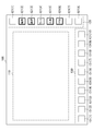
- the display control unit 215 has, for example, the work items “creation / editing of machining program”, “selection of machining program”, and “work” for each of the soft keys 121 (2) to 121 (6). Assign functions to transition to the setting screens of "Measurement and setting", “Tool setting”, and “Custom macro variable setting”, and “Edit”, “Select”, “Work”, “Tool”, and “Macro”. A name such as "" may be displayed. In addition, the display control unit 215 determines the display form (for example, softkey border color, border type, border thickness, softkey background color, etc.) that has not been set / updated. , It may be displayed differently from the display form of the optional setting.
- the display form for example, softkey border color, border type, border thickness, softkey background color, etc.
- the display control unit 21 has the work items “creation / editing of machining program”, “selection of machining program”, and “measurement and setting of workpiece” for each of the soft keys 121 (2) to 121 (6). , “Tool settings”, and “Custom macro variable settings” may be displayed.
- the display control unit 2115 the work items "creation / editing of machining program”, “selection of machining program”, “tool setting”, and "custom macro variable setting” are incomplete / unupdated essential settings.
- the frames of the softkeys 121 (2), 121 (3), 121 (5), and 121 (6) are displayed with thick lines.
- the display control unit 215 uses the soft key 121 (to emphasize that the work item "measurement and setting of work” is an incomplete / unupdated optional setting.
- the frame of 4) is displayed with a thick broken line. By doing so, the worker does not have to memorize what more work must be done, and work omission can be prevented.
- the display control unit 215 highlights by changing the line type according to the required setting and the optional setting, but the present invention is not limited to this.
- the display control unit 215 sets an unset / unupdated mandatory setting display form (for example, softkey border color, border type, border thickness, softkey background color, etc.). , It may be displayed differently from the display form of the optional setting.
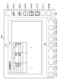
- the display control unit 215 is shown in FIG. 5, for example, when the “edit” softkey 121 (2) is pressed by an operator via the touch panel (not shown) of the display unit 220 on the screen 100 of FIG. As described above, the setting screen 111 of the work item "creation / editing of the machining program" is displayed in the setting display area 110. When a new machining program is created, the display control unit 215 displays a new setting screen 111 in a clean state, and is created by a worker's input operation via a touch panel (not shown) of the display unit 220. A new machining program may be displayed on the setting screen 111.
- the display control unit 215 uses a touch panel (not shown) of the display unit 220 when the machining program is created by partially modifying the existing machining program such that the shapes of the parts are partially different.
- the copied existing machining program may be displayed on the setting screen 111 based on the input operation of the worker via the user.
- the display control unit 215 may display the machining program partially changed by the input operation of the worker via the touch panel (not shown) of the display unit 220 on the setting screen 111. If the machine tool 10 is a machine with one system, at least one machining program is required, and if the machine tool 10 is a machine with two or more systems, at least one machining program is required for each system. be.
- the display control unit 215 sets the display form of the completed work item (for example, border color, type, thickness, background color, effect, etc.) to be different from the display form of the required setting and the optional setting. It is preferable to display. As shown in FIG. 6, the display control unit 215 displays, for example, the configuration of a folder for storing the files of each machining program on the left side of the setting screen 112, and is set for each system on the right side of the setting screen 112 to control the control device 20. A list of machining programs registered in may be displayed. For example, a machining program is selected and set for each system based on an input operation of a worker via a touch panel (not shown) of the display unit 220. In the case of FIG. 6, for example, when the machine tool 10 has a machine configuration of two systems, even if the machining program "O0022" is set as the main program in one system and the machining program "O0001" is set as the main program in the two systems. good.
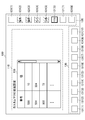
- the display control unit 215 performs the operation shown in FIG. 6 when the soft key 121 (4) of the “work” on the screen 100 of FIG. 6 is pressed by the worker via the touch panel (not shown) of the display unit 220.
- the screen 100 transitioned from the setting screen 112 of the item “selection of machining program” to the setting screen 113 of the work item “work measurement and setting” of FIG. 7 is displayed.
- the display control unit 215 is soft because the work states of the work items "creation / edit of machining program” and "selection of machining program” are completed or updated in the work item table 231.
- the keys 121 (2) and 121 (3) may be shaded to indicate completion. As shown in FIG.
- the machine tool 10 may be a machine tool having 5 axes other than the 3 axes, and the coordinates of the work are set in the same manner as in the case of the 3 axes. If the machine tool 10 does not have a pallet changer, the work item "Measurement and setting of workpiece" must be set as an indispensable setting every time the workpiece is set in the machine tool 10.
- the display control unit 215 performs the operation shown in FIG. 7 when the soft key 121 (5) of the “tool” on the screen 100 of FIG. 7 is pressed by the worker via the touch panel (not shown) of the display unit 220.
- the screen 100 transitioned from the setting screen 113 of the item “work measurement and setting” to the setting screen 114 of the work item “tool setting” of FIG. 8 is displayed.
- the display control unit 215 displays the work states of the work items “creation / editing of machining program”, “selection of machining program”, and “measurement and setting of work” in the work item table 231.
- the softkeys 121 (2) -121 (4) may be shaded to indicate completion because of the completed or updated state. As shown in FIG.
- the control device 20 acquires a tool management table (not shown) stored in a storage unit (not shown) of the machine tool 10, and the acquired tool management table (not shown). It may be set based on (not).
- the display control unit 215 performs the operation shown in FIG. 8 when the soft key 121 (6) of the “macro” on the screen 100 of FIG. 8 is pressed by the worker via the touch panel (not shown) of the display unit 220.
- the screen 100 transitioned from the setting screen 114 of the item “tool setting” to the setting screen 115 of the work item "custom macro variable setting” of FIG. 9 is displayed.
- the display control unit 215 displays the work items "creation / editing of machining program", “selection of machining program”, "measurement and setting of workpiece", and “tool” in the work item table 231.
- the softkeys 121 (2) to 121 (5) may be displayed in a shaded manner indicating completion.
- the display control unit 215 displays, for example, the values set for each custom macro variable (for example, “500”, “501”, “502”, etc.) on the setting screen 115.
- the display control unit 215 completes the softkey 121 (6) of the work item "custom macro variable setting” based on the work item table 231. It may be displayed in the shaded area shown.
- the custom macro variable must match the description of the machining program. That is, if you change the main program, you must also change the custom macro variables. However, in the case of a machining program that does not use custom macro variables, no setting is required.
- the display control unit 215 When the display control unit 215 receives an alarm from the notification unit 217, which will be described later, that the machining operation is not permitted because there is an incomplete or unupdated mandatory setting, "because there is an incomplete or unupdated mandatory setting”. Warnings such as “Do not allow machining operation” or "Make required settings before starting machining” may be displayed on the display unit 220. In addition, the display control unit 215 may display a warning on the display unit 220 and automatically transition to an incomplete or unupdated mandatory setting setting screen.
- the motion control unit 216 monitors and controls the operating states of the machine tool 10 and the control device 20. Specifically, the motion control unit 216 receives an instruction for the machining operation, for example, the start button (not shown) of the machining operation provided on the machine tool 10 or the control device 20 is pressed by the operator. In this case, it is confirmed whether or not there is an incomplete or unupdated mandatory setting based on the work item table 231 stored in the storage unit 230. The motion control unit 216 does not allow the machining operation of the machine tool 10 when there is an incomplete or unupdated mandatory setting. Then, the operation control unit 216 may output a warning to the notification unit 217, which will be described later, that the machining operation is not permitted because there is an incomplete or unupdated essential setting. By doing so, it is possible to avoid accidentally executing machining when the required setting is omitted, and it is possible to prevent damage to the machine tool 10 and the work due to a work error.
- an instruction for the machining operation for example, the start button (not shown)
- the notification unit 217 outputs a warning that the machining operation is not permitted because there is an incomplete or unupdated mandatory setting based on the instruction from the operation control unit 216, and the output warning is output via the display control unit 215. It may be displayed on the display unit 220.
- FIG. 10 is a flowchart illustrating the setting process of the control device 20. The flow shown here is executed every time the setup work is performed.
- step S11 the extraction unit 213 extracts each of the plurality of work items of the setup for the next machining in the machine tool 10 as essential settings or optional settings based on the machine configuration of the machine tool 10.
- step S12 the determination unit 214 is the work of the setup work extracted as an essential setting or an optional setting according to the operation content by the worker from the completion of the latest machining detected by the operation detection unit 212 to the present time. It is dynamically determined whether each of the items corresponds to either the required setting or the optional setting.
- step S13 the display control unit 215 displays the softkey 121 of each work item on the display unit 220 so that either the required setting or the optional setting can be determined based on the determination result.
- step S14 the display control unit 215 displays the screen 100 including the setting screen of the work item selected by the worker pressing the soft key 121 via the touch panel (not shown) of the display unit 220.
- step S15 each time the display control unit 215 determines that the setting of the work item selected in step S14 has been completed by the operation control unit 216, the display control unit 215 displays the soft key 121 of the work item to indicate that it has been completed. indicate.
- step S16 the determination unit 214 determines whether or not there is an incomplete or unupdated work item based on the work item table 231 stored in the storage unit 230. If there are unfinished or unupdated work items, the process returns to step S12. On the other hand, if there are no incomplete or unupdated work items, the process ends.
- step S16 when the operation control unit 216 receives an instruction from the operator for the machining operation of the machine tool 10, the operation control unit 216 is incomplete or unupdated based on the work item table 231 stored in the storage unit 230. You may check whether there is a required setting of. Then, when there is an incomplete or unupdated mandatory setting, the motion control unit 216 may output a warning to the notification unit 217 that the machining operation is not permitted because there is an incomplete or unupdated mandatory setting. The display control unit 215 automatically transitions to the setting screen of the incomplete or unupdated required setting with a warning that the machining operation is not permitted because there is an incomplete or unupdated required setting output from the notification unit 217. May be good. By doing so, it is possible to prevent damage to the machine tool 10 and the work due to work mistakes.
- the control device 20 of one embodiment extracts each of the plurality of work items of the setup work for the next machining in the machine tool 10 as essential settings or optional settings based on the machine configuration of the machine tool 10.
- the control device 20 has a mandatory setting or an optional setting for each of the work items of the setup work extracted as a mandatory setting or an optional setting according to the operation content in the setup work for the machine tool 10 from the completion of the latest machining to the present time. Dynamically determine if any of the settings apply.
- the control device 20 dynamically displays each of the work items determined to be the required setting or the optional setting so as to be discriminateable.
- control device 20 can easily confirm the work status without remembering what work the operator has to perform in the setup work, and can prevent work omissions. Further, if there is an omission of the required setting, the control device 20 does not allow the machine tool 10 to execute machining. This makes it possible to prevent damage to the machine tool 10 and the work due to work mistakes.
- control device 20 is not limited to the above-described embodiment, and includes deformation, improvement, and the like within a range in which the object can be achieved.
- the control device 20 allocates each work item of the setup work to the softkey 121 of the vertical key display area 120, but is not limited thereto.
- the control device 20 may display work items hierarchically.
- FIG. 11 is a diagram showing an example of the hierarchical display of the softkey 121.
- the control device 20 assigns a function of "item selection" for hierarchically displaying work items to one softkey 121 (2) among the softkeys 121 of the first layer.
- the control device 20 sets, for example, the soft keys 121A (1) to 121A (8) of the work items set in the second layer to the vertical key display area 120. It may be displayed.
- the second-layer softkeys 121A (1) -121A (8) correspond to each of the first-layer softkeys 121 (1) -121 (8).
- the softkey 121 (2) of the "item selection" in the first layer has an incomplete or unupdated required setting when the work item in the second layer has an incomplete or unupdated required setting. It is preferable that it is displayed so as to emphasize. Further, the soft key 121 (2) of the "item selection" in the first layer is not completed or unupdated if there is no required setting in the work item in the second layer and there is an incomplete or unupdated optional setting. It should be displayed to emphasize that there are optional settings that have been completed or have not been updated.
- each function included in the control device 20 in one embodiment can be realized by hardware, software, or a combination thereof.
- what is realized by software means that it is realized by a computer reading and executing a program.
- Non-transitory computer-readable media include various types of tangible recording media (Tangible storage media).
- Examples of non-temporary computer-readable media include magnetic recording media (eg, flexible disks, magnetic tapes, hard disk drives), magneto-optical recording media (eg, magneto-optical disks), CD-ROMs (Read Only Memory), CD- Includes R, CD-R / W, and semiconductor memory (for example, mask ROM, PROM (Programmable ROM), EPROM (Erasable PROM), flash ROM, RAM).
- the program may also be supplied to the computer by various types of temporary computer-readable media (Transition computer readable medium). Examples of temporary computer-readable media include electrical, optical, and electromagnetic waves.
- the temporary computer-readable medium can supply the program to the computer via a wired communication path such as an electric wire and an optical fiber, or a wireless communication path.
- the step of describing the program recorded on the recording medium is not only the processing performed in chronological order according to the order, but also the processing executed in parallel or individually even if it is not necessarily processed in chronological order. Also includes.
- control device of the present disclosure can take various embodiments having the following configurations.
- the control device 20 of the present disclosure is a plurality of control devices 20 included in the setup work for the next machining in the machine tool 10 based on the machine configuration including at least one of the number of axes and the number of systems in the machine tool 10 to be set.
- Judgment unit 214 that dynamically determines whether each of the plurality of work items extracted as settings corresponds to either the required setting or the optional setting, and when the required setting is incomplete or not updated, the machine tool It includes an operation control unit 216 that does not allow machining operations. According to the control device 20, it is possible to easily confirm the work status in the setup work without having to remember what work the worker has to perform.
- control device 20 In the control device 20 according to (1), display control is displayed on the display unit 220 so that each of a plurality of work items can be discriminated as either an essential setting or an optional setting based on the determination result of the determination unit 214. A unit 215 may be further provided. By doing so, the control device 20 can surely set the essential settings.
- the operation control unit 216 further includes a notification unit 217 that outputs a warning when the operation control unit 216 does not permit the machining operation of the machine tool 10, and the display control unit 215 displays a warning. It may be displayed on the unit 220. By doing so, the control device 20 can prevent the machine tool 10 and the work from being damaged due to a work error.
- the display control unit displays an incomplete or unupdated mandatory setting setting screen. You may make a transition. By doing so, the control device 20 can surely set the essential settings before the machining operation.
- the display control unit 215 can discriminate a work item whose setting has been completed or updated from a plurality of work items as an essential setting or an optional setting. It may be displayed in. By doing so, the control device 20 can prevent the machine tool 10 and the work from being damaged due to a work mistake when the work is omitted.
- Control system 10 Machine tool 20
- Control device 210 Control unit 211 Machining completion detection unit 212 Operation detection unit 213 Extraction unit 214 Judgment unit 215 Display control unit 216 Operation control unit 217 Notification unit 220 Display unit 230 Storage unit 231 Work item table
Landscapes
- Engineering & Computer Science (AREA)
- Physics & Mathematics (AREA)
- Human Computer Interaction (AREA)
- Manufacturing & Machinery (AREA)
- General Physics & Mathematics (AREA)
- Automation & Control Theory (AREA)
- Geometry (AREA)
- Numerical Control (AREA)
Abstract
Description
この点、加工選択画面で所望の加工の加工形態を選択させ、選択された加工形態を設定する画面を予め設定された順序に従って表示し、当該加工形態に必要な所要データを順番に入力させることで、自動的に所望の加工プログラムを作成する技術が知られている。例えば、特許文献1参照。
<一実施形態>
図1は、一実施形態に係る制御システムの機能的構成例を示す機能ブロック図である。図1に示すように、制御システム1は、工作機械10、及び制御装置20を有する。
なお、制御装置20は、工作機械10に含まれてもよい。
なお、工作機械10は、例えば、工作機械10に含まれるHDD(Hard Disk Drive)等の図示しない記憶部に、工作機械10の主軸(図示しない)に取付けられるすべての工具を管理する工具管理テーブル(図示しない)を記憶してもよい。そして、後述する制御装置20は、段取り作業時に加工プログラムに設定された工具番号等に基づいて、工具名、工具径、工具長等を工作機械10の工具管理テーブル(図示しない)から取得してもよい。
また、工作機械10は、例えば、工作機械10の記憶部(図示しない)に、工作機械10の軸数、系統数、パレットチェンジャの有無等の機械構成を示す構成情報を記憶してもよい。そして、後述する制御装置20は、段取り作業時に、工作機械10の軸数、系統数、パレットチェンジャの有無等の機械構成を、工作機械10の構成情報から取得してもよい。
制御装置20は、当業者にとって公知の数値制御装置である。制御装置20は、制御装置20に含まれるタッチパネル等の入力装置(図示しない)を介して受け付けた作業員からの指示、又は実行する加工プログラムに基づいて動作指令を生成し、生成した動作指令を工作機械10に送信する。これにより、制御装置20は、工作機械10の動作を制御する。
なお、ソフトキー121(1)-121(m)に、画面操作の機能が割り当てられてもよく、ソフトキー131(1)-131(n)に、作業項目毎の設定画面を遷移する機能が割り当てられてもよい。
以下、m=8及びn=10として説明するが、mが8以外、及びnが10以外の数でも同様に動作する。また、ソフトキー121(1)-121(8)のそれぞれを個々に区別する必要がない場合、これらをまとめて「ソフトキー121」ともいう。また、ソフトキー131(1)-131(10)のそれぞれを個々に区別する必要がない場合、これらをまとめて「ソフトキー131」ともいう。
図3は、作業項目テーブル231の一例を示す図である。
図3に示すように、作業項目テーブル231は、例えば、工作機械10における直近の加工の完了から現時点までの間の工作機械10における次の加工の段取り作業における「作業項目」を含む。作業項目テーブル231は、各作業項目に対応して「必須/任意」、及び「作業状態」を含む。
作業項目テーブル231内の「作業項目」は、直近の加工の完了から現時点までの間の工作機械10における次の加工の段取り作業において必要となる作業項目が設定される。図3では、作業項目として、「加工プログラムの作成/編集」、「加工プログラムの選択」、「ワークの測定及び設定」、「工具の設定」、及び「カスタムマクロ変数の設定」等が設定されてもよい。
作業項目テーブル231内の「作業状態」は、後述する判定部214の判定結果に基づいて、未完了若しくは未更新、又は完了若しくは未更新のいずれかが格納される。
制御部210は、CPU(Central Processing Unit)、ROM、RAM、CMOS(Complementary Metal-Oxide-Semiconductor)メモリ等を有し、これらはバスを介して相互に通信可能に構成される、当業者にとって公知のものである。
CPUは制御装置20を全体的に制御するプロセッサである。CPUは、ROMに格納されたシステムプログラム及びアプリケーションプログラムを、バスを介して読み出し、前記システムプログラム及びアプリケーションプログラムに従って制御装置20全体を制御する。これにより、図1に示すように、制御部210が、加工完了検知部211、操作検知部212、抽出部213、判定部214、表示制御部215、動作制御部216、及び通知部217の機能を実現するように構成される。RAMには一時的な計算データや表示データ等の各種データが格納される。また、CMOSメモリは図示しないバッテリでバックアップされ、制御装置20の電源がオフされても記憶状態が保持される不揮発性メモリとして構成される。
具体的には、操作検知部212は、例えば、加工完了検知部211により直近の加工の完了が検知されてから現時点までの間の工作機械10における次の加工の段取り作業に係る操作(例えば、各系統のメインプログラムの選択変更の操作、各系統のメインプログラムの変更の操作、各系統の工具番号(T番号)又は工具オフセット値の変更の操作、ワーク座標の変更の操作、及びカスタムマクロ変数の変更の操作等)の操作内容を検知する。
抽出部213は、設定対象の工作機械10における軸数及び系統数の少なくとも1つを含む機械構成に基づいて、工作機械10における次の加工に対する段取り作業に含まれる複数の作業項目の各々を設定が必須設定又は設定が任意設定として抽出する。抽出部213は、抽出の結果に基づいて、作業項目テーブル231の「必須/任意」を更新する。
具体的には、抽出部213は、例えば、加工完了検知部211により直近の加工の完了が検知された場合、工作機械10から工作機械10の軸数、系統数、パレットチェンジャの有無等の機械構成を示す構成情報を取得する。抽出部213は、取得した構成情報において工作機械10にパレットチェンジャがある場合、加工毎にワーク座標の測定及び設定が不要となることから、作業項目「ワークの測定及び設定」を「任意設定」として抽出してもよい。一方、抽出部213は、工作機械10にパレットチェンジャがない場合、加工毎にワーク座標の測定及び設定が必要となることから、作業項目「ワークの測定及び設定」を「必須設定」として抽出してもよい。
また、抽出部213は、取得した構成情報の軸数に基づいて、軸数分のワーク座標の設定が必要となることから、作業項目「ワークの測定及び設定」を「必須設定」として抽出してもよい。
また、抽出部213は、取得した構成情報における系統数に基づいて、系統数毎にメインプログラムの設定、及び系統数毎の工具オフセットの設定が必要となることから、作業項目「加工プログラムの選択」、及び「工具の設定」を「必須設定」として抽出してもよい。
判定部214は、抽出部213により段取り作業の各作業項目が必須設定又は任意設定として抽出された後、操作検知部212により検知された段取り作業における操作内容に応じて、必須設定又は任意設定として抽出された段取り作業の作業項目の各々について必須設定又は任意設定のいずれかに該当するかを動的に判定する。
具体的には、判定部214は、操作検知部212により検知された操作内容において各系統のメインプログラムの選択変更がある場合、直近の加工終了時点の設定に対して、工具オフセットの設定が必要となるため、抽出部213により任意設定として抽出されたとしても作業項目「工具の設定」を「必須設定」と判定し、作業項目テーブル231の「必須/任意」を動的に変更する。また、判定部214は、各系統のメインプログラムの選択変更がある場合、直近の加工終了時点の設定に対して、カスタムマクロ変数の変更が必要となるため、抽出部213により任意設定として抽出されたとしても作業項目「カスタムマクロ変数の設定」を「必須設定」と判定し、作業項目テーブル231の「必須/任意」を動的に変更する。
また、作業項目「加工プログラムの選択」の作業において、操作検知部212が作業員により「設定」のソフトキー131が押下される等の操作を検知し、制御装置20にメインプログラムが設定された場合、判定部214は、作業項目テーブル231の作業項目「加工プログラムの選択」の「作業状態」を未完了又は未更新の状態から完了又は更新の状態に更新してもよい。
また、作業項目「ワークの測定及び設定」の作業において、操作検知部212が作業員により「設定」のソフトキー131が押下される等の操作を検知し、制御装置20にワーク座標が設定された場合、判定部214は、作業項目テーブル231の作業項目「ワークの測定及び設定」の「作業状態」を未完了又は未更新の状態から完了又は更新の状態に更新してもよい。
また、作業項目「カスタムマクロ変数の設定」の作業において、操作検知部212が作業員により「設定」のソフトキー131が押下される等の操作を検知し、制御装置20にカスタムマクロ変数が設定された場合、判定部214は、作業項目テーブル231の作業項目「カスタムマクロ変数の設定」の「作業状態」を未完了又は未更新の状態から完了又は更新の状態に更新してもよい。
表示制御部215は、作業項目「加工プログラムの作成/編集」、「加工プログラムの選択」、「ワークの測定及び設定」、「工具の設定」、及び「カスタムマクロ変数の設定」の各々を、判定部214の判定結果に基づいて必須設定又は任意設定のいずれか判別可能に動的に変化させて表示部220に表示する。
以下、作業項目「加工プログラムの作成/編集」、「加工プログラムの選択」、「工具の設定」、及び「カスタムマクロ変数の設定」が判定部214により必須設定と判定され、作業項目「ワークの測定及び設定」が判定部214により任意設定と判定された場合について説明する。ただし、作業項目「加工プログラムの作成/編集」、「加工プログラムの選択」、「ワークの測定及び設定」、「工具の設定」、及び「カスタムマクロ変数の設定」の各々の必須設定又は任意設定が、判定部214の判定結果に応じて動的に変化したとしても同様である。
そうすることで、作業者はあと何の作業をやらなければならないかを記憶する必要な無くなり、作業漏れを防ぐことができる。
なお、表示制御部215は、必須設定及び任意設定に応じて線種を変えて強調表示したが、これに限定されない。例えば、表示制御部215は、未設定/未更新の必須設定の表示形態(例えば、ソフトキーの枠線の色、枠線の種類、枠線の太さ、ソフトキーの背景の色等)を、任意設定の表示形態と異なるように表示してもよい。
表示制御部215は、新規に加工プログラムが作成される場合、新規のまっさらな状態の設定画面111を表示し、表示部220のタッチパネル(図示しない)を介した作業員の入力操作により作成された新規の加工プログラムを設定画面111に表示してもよい。
また、表示制御部215は、例えば、部品の形状が部分的に異なる等のように既存の加工プログラムを一部変更して加工プログラムが作成される場合、表示部220のタッチパネル(図示しない)を介した作業員の入力操作に基づいて、コピーした既存の加工プログラムを設定画面111に表示してもよい。表示制御部215は、表示部220のタッチパネル(図示しない)を介した作業員の入力操作により部分的に変更された加工プログラムを設定画面111に表示してもよい。
なお、工作機械10が1系統の機械の場合、最低1つ以上の加工プログラムが必要であり、工作機械10が2系統以上の機械の場合、系統毎に最低1つ以上の加工プログラムが必要である。
なお、表示制御部215は、完了済の作業項目の表示形態(例えば、枠線の色、種類、太さ、背景の色、効果等)を、必須設定及び任意設定の表示形態と異なるように表示することが好ましい。
図6に示すように、表示制御部215は、例えば、設定画面112の左側に各加工プログラムのファイルを格納するフォルダの構成を表示し、設定画面112の右側に系統毎にセットされ制御装置20に登録されている加工プログラムの一覧を表示してもよい。例えば、表示部220のタッチパネル(図示しない)を介した作業員の入力操作に基づいて、系統毎に加工プログラムが選択されてセットされる。図6の場合、例えば、工作機械10が2系統の機械構成の場合、1系統に加工プログラム「O0022」がメインプログラムとして設定され、2系統に加工プログラム「O0001」がメインプログラムとして設定されてもよい。
図7に示すように、表示制御部215は、例えば、工作機械10が3軸の工作機械の場合、工作機械10に載置されたワークに対して設定されたX軸、Y軸、Z軸それぞれのワーク座標を設定画面113に表示する。
ここで、ワーク座標の設定は、例えば、作業員が工作機械10に取り付けられたタッチセンサ等をハンドル操作で動かし、X、Y、Z方向それぞれのワークの端面に接触させることで、X、Y、Z方向それぞれの値が測定される。制御装置20は、測定されたX、Y、Z方向それぞれの値を、ワーク座標として設定する。
なお、工作機械10は3軸以外の5軸等の工作機械でもよく、ワークの座標は3軸の場合と同様に設定される。
また、工作機械10にパレットチェンジャがない場合、作業項目「ワークの測定及び設定」は、必須設定として、ワークが工作機械10にセットされる毎に必ず設定されなければならない。
図8に示すように、表示制御部215は、例えば、設定された工具番号、工具名、工具径、工具長等を設定画面114に表示する。
ここで、工具の設定は、例えば、ツールプリセッタやタッチセンサ等を用いて工具のサイズを測定し、測定した値を工具のオフセット(工具径、工具長)として設定する。
また、工具番号(T番号)は、加工プログラムの記載に合わせなければならない。例えば、加工プログラムで「T1」を使用する設定をしている場合、「T1」は「ドリル」を設定しなければならない。換言すれば、メインプログラムを変更した場合は、必ず各工具番号(T番号)にセットする工具オフセットも変更しなければならない。
また、工具番号(T番号)及び工具名については、例えば、制御装置20が工作機械10の図示しない記憶部に記憶された工具管理テーブル(図示しない)を取得し、取得した工具管理テーブル(図示しない)に基づいて設定されてもよい。
図9に示すように、表示制御部215は、例えば、カスタムマクロ変数(例えば、「500」、「501」、「502」等)毎に設定された値を設定画面115に表示する。
表示制御部215は、作業項目「カスタムマクロ変数の設定」の作業が終了した場合、作業項目テーブル231に基づいて、作業項目「カスタムマクロ変数の設定」のソフトキー121(6)を完了済を示す網掛けで表示してもよい。
なお、カスタムマクロ変数は、加工プログラムの記載に合わせなければならない。すなわち、メインプログラムを変更した場合は、必ずカスタムマクロ変数も変更しなければならない。ただし、カスタムマクロ変数を使用しない加工プログラムの場合は、設定不要である。
具体的には、動作制御部216は、例えば、工作機械10又は制御装置20に設けられた加工動作の開始ボタン(図示しない)等が作業者により押下される等、加工動作の指示を受けた場合、記憶部230に記憶された作業項目テーブル231に基づいて、未完了又は未更新の必須設定があるか否かを確認する。動作制御部216は、未完了又は未更新の必須設定がある場合に、工作機械10の加工動作を許可しない。そして、動作制御部216は、後述する通知部217に対して未完了又は未更新の必須設定があるため加工動作を許可しない旨の警告を出力させてもよい。
そうすることで、必須設定が作業漏れした場合に、誤って加工実行させることを回避でき、作業ミスによる工作機械10やワークの破損を防ぐことができる。
次に、図10を参照しながら、制御装置20の設定処理の流れを説明する。
図10は、制御装置20の設定処理について説明するフローチャートである。ここで示すフローは、段取り作業が行われる度に実行される。
そうすることで、作業ミスによる工作機械10やワークの破損を防ぐことができる。
また、必須設定の設定漏れがある場合、制御装置20は、工作機械10の加工実行を許可しないようにする。これにより、作業ミスによる工作機械10やワークの破損を防ぐことができる。
上述の実施形態では、制御装置20は、段取り作業の作業項目の各々を縦キー表示領域120のソフトキー121に割り当てたがこれに限定されない。例えば、制御装置20は、作業項目を階層表示してもよい。
図11は、ソフトキー121の階層表示の一例を示す図である。
図11に示すように、制御装置20は、1階層目のソフトキー121のうち、1つのソフトキー121(2)に作業項目を階層表示する「項目選択」の機能を割り当てる。ソフトキー121(2)が作業者により押下された場合、制御装置20は、例えば、2階層目に設定された作業項目のソフトキー121A(1)-121A(8)を縦キー表示領域120に表示してもよい。なお、2階層目のソフトキー121A(1)-121A(8)は、1階層目のソフトキー121(1)-121(8)の各々に対応する。
この場合、1階層目の「項目選択」のソフトキー121(2)は、2階層目の作業項目に未完了又は未更新の必須設定がある場合、未完了又は未更新の必須設定があることを強調するように表示されることが好ましい。また、1階層目の「項目選択」のソフトキー121(2)は、2階層目の作業項目に未完了又は未更新の必須設定がなく、未完了又は未更新の任意設定がある場合、未完了又は未更新の任意設定があることを強調するように表示されることが好ましい。
この制御装置20によれば、段取り作業において、作業者があと何の作業を行わなければならないかを記憶することなく作業状況を容易に確認できる。
そうすることで、制御装置20は、必須設定の設定を確実に行うことができる。
そうすることで、制御装置20は、作業ミスによる工作機械10やワークの破損を防ぐことができる。
そうすることで、制御装置20は、加工動作の前に必須設定の設定を確実に行うことができる。
そうすることで、制御装置20は、作業漏れをした場合、作業ミスによる工作機械10やワークの破損を防ぐことができる。
10 工作機械
20 制御装置
210 制御部
211 加工完了検知部
212 操作検知部
213 抽出部
214 判定部
215 表示制御部
216 動作制御部
217 通知部
220 表示部
230 記憶部
231 作業項目テーブル
Claims (5)
- 設定対象の工作機械における軸数及び系統数の少なくとも1つを含む機械構成に基づいて、前記工作機械における次の加工に対する段取り作業に含まれる複数の作業項目の各々を必須設定又は任意設定として抽出する抽出部と、
前記工作機械による直近の加工の完了から現時点までの間の前記工作機械に対する前記段取り作業における操作内容に応じて、必須設定又は任意設定として抽出された前記複数の作業項目の各々について必須設定又は任意設定のいずれかに該当するかを動的に判定する判定部と、
未完了又は未更新の前記必須設定がある場合に、前記工作機械の加工動作を許可しない動作制御部と、
を備える制御装置。 - 前記判定部の判定結果に基づいて、前記複数の作業項目の各々を前記必須設定又は前記任意設定のいずれか判別可能に表示部に表示する表示制御部をさらに備える、請求項1に記載の制御装置。
- 前記動作制御部が前記工作機械の加工動作を許可しない場合、警告を出力する通知部をさらに備え、
前記表示制御部は、前記警告を前記表示部に表示する、請求項2に記載の制御装置。 - 前記表示制御部は、前記動作制御部が前記工作機械の加工動作を許可しない場合、未完了又は未更新の前記必須設定の設定画面に遷移する、請求項2又は請求項3に記載の制御装置。
- 前記表示制御部は、前記複数の作業項目のうち設定が完了又は更新した作業項目を前記必須設定及び前記任意設定と判別可能に表示する、請求項2から請求項4のいずれか1項に記載の制御装置。
Priority Applications (4)
| Application Number | Priority Date | Filing Date | Title |
|---|---|---|---|
| DE112021002049.8T DE112021002049T5 (de) | 2020-04-02 | 2021-03-26 | Steuervorrichtung |
| JP2022512116A JP7469463B2 (ja) | 2020-04-02 | 2021-03-26 | 制御装置 |
| CN202180025190.0A CN115349110B (zh) | 2020-04-02 | 2021-03-26 | 控制装置 |
| US17/914,542 US20230143968A1 (en) | 2020-04-02 | 2021-03-26 | Control device |
Applications Claiming Priority (2)
| Application Number | Priority Date | Filing Date | Title |
|---|---|---|---|
| JP2020-066620 | 2020-04-02 | ||
| JP2020066620 | 2020-04-02 |
Publications (1)
| Publication Number | Publication Date |
|---|---|
| WO2021200653A1 true WO2021200653A1 (ja) | 2021-10-07 |
Family
ID=77929160
Family Applications (1)
| Application Number | Title | Priority Date | Filing Date |
|---|---|---|---|
| PCT/JP2021/012860 Ceased WO2021200653A1 (ja) | 2020-04-02 | 2021-03-26 | 制御装置 |
Country Status (5)
| Country | Link |
|---|---|
| US (1) | US20230143968A1 (ja) |
| JP (1) | JP7469463B2 (ja) |
| CN (1) | CN115349110B (ja) |
| DE (1) | DE112021002049T5 (ja) |
| WO (1) | WO2021200653A1 (ja) |
Citations (3)
| Publication number | Priority date | Publication date | Assignee | Title |
|---|---|---|---|---|
| JPH06250722A (ja) * | 1993-02-23 | 1994-09-09 | Fanuc Ltd | 対話形数値制御装置 |
| JP2003186510A (ja) * | 2001-12-17 | 2003-07-04 | Amada Denshi:Kk | Ncデータ適正化方法及びそのシステム |
| WO2016051544A1 (ja) * | 2014-09-30 | 2016-04-07 | 株式会社牧野フライス製作所 | 工作機械の制御装置 |
Family Cites Families (15)
| Publication number | Priority date | Publication date | Assignee | Title |
|---|---|---|---|---|
| JP2927512B2 (ja) * | 1990-07-04 | 1999-07-28 | 株式会社アマダメトレックス | Nc加工機の段取り情報処理装置 |
| JP2853755B2 (ja) * | 1992-12-02 | 1999-02-03 | 三菱電機株式会社 | 数値制御加工装置 |
| JPH11143513A (ja) * | 1997-11-05 | 1999-05-28 | Okuma Corp | 数値制御情報作成機能を有する数値制御装置 |
| WO2000012258A1 (en) * | 1998-08-28 | 2000-03-09 | Mori Seiki Co., Ltd. | Method and apparatus for optimizing nc programs in nc machining |
| JP2000126937A (ja) | 1998-10-27 | 2000-05-09 | Sodick Co Ltd | 放電加工におけるプログラミング装置の設定装置 |
| US6970764B2 (en) * | 2002-12-26 | 2005-11-29 | Mitsubishi Denki Kabushiki Kaisha | Machining program producing apparatus |
| JP4672299B2 (ja) * | 2004-07-26 | 2011-04-20 | ヤマザキマザック株式会社 | 工作機械のバランサ取付角度算出方法、及び工作機械 |
| JP4442762B2 (ja) * | 2004-08-23 | 2010-03-31 | 株式会社森精機製作所 | Nc工作機械の制御装置 |
| JP2006293537A (ja) * | 2005-04-07 | 2006-10-26 | Fanuc Ltd | 数値制御装置 |
| JP5346840B2 (ja) * | 2010-02-17 | 2013-11-20 | 日精樹脂工業株式会社 | 射出成形機の段取支援方法及び装置 |
| CN102689236B (zh) * | 2012-06-01 | 2014-08-13 | 李国庆 | 一种多主轴数控机床 |
| JP6486005B2 (ja) * | 2014-01-17 | 2019-03-20 | 蛇の目ミシン工業株式会社 | ロボット、ロボットの制御方法、及びロボットの制御プログラム |
| WO2018098399A1 (en) * | 2016-11-25 | 2018-05-31 | Glowforge Inc. | Controlled deceleration of moveable components in a computer numerically controlled machine |
| EP3444686B1 (en) * | 2017-08-15 | 2021-12-22 | GF Machining Solutions AG | Method for using a geometrical probe with a spindle of a machine tool, and machine tool configured to carry out such a method |
| JP6828641B2 (ja) * | 2017-08-31 | 2021-02-10 | ブラザー工業株式会社 | 数値制御装置と装着判定基準設定方法 |
-
2021
- 2021-03-26 WO PCT/JP2021/012860 patent/WO2021200653A1/ja not_active Ceased
- 2021-03-26 US US17/914,542 patent/US20230143968A1/en active Pending
- 2021-03-26 DE DE112021002049.8T patent/DE112021002049T5/de active Pending
- 2021-03-26 CN CN202180025190.0A patent/CN115349110B/zh active Active
- 2021-03-26 JP JP2022512116A patent/JP7469463B2/ja active Active
Patent Citations (3)
| Publication number | Priority date | Publication date | Assignee | Title |
|---|---|---|---|---|
| JPH06250722A (ja) * | 1993-02-23 | 1994-09-09 | Fanuc Ltd | 対話形数値制御装置 |
| JP2003186510A (ja) * | 2001-12-17 | 2003-07-04 | Amada Denshi:Kk | Ncデータ適正化方法及びそのシステム |
| WO2016051544A1 (ja) * | 2014-09-30 | 2016-04-07 | 株式会社牧野フライス製作所 | 工作機械の制御装置 |
Also Published As
| Publication number | Publication date |
|---|---|
| DE112021002049T5 (de) | 2023-01-12 |
| US20230143968A1 (en) | 2023-05-11 |
| CN115349110B (zh) | 2025-09-02 |
| JPWO2021200653A1 (ja) | 2021-10-07 |
| CN115349110A (zh) | 2022-11-15 |
| JP7469463B2 (ja) | 2024-04-16 |
Similar Documents
| Publication | Publication Date | Title |
|---|---|---|
| JP6703967B2 (ja) | 工具管理装置およびこれを備えた工作機械 | |
| CN106796425B (zh) | 机床的控制装置 | |
| WO2015097886A1 (ja) | 加工情報管理装置および工具経路生成装置 | |
| CN105549528A (zh) | 机床数控系统 | |
| US10139805B2 (en) | Ladder diagram monitoring device capable of additionally displaying operation situation of CNC in comment | |
| US10698872B2 (en) | Data collection management system, method, and recording medium encoded with a program for managing collection of data of plurality of machines | |
| US11402819B2 (en) | Screen creation device and screen creation system | |
| JPWO2015170382A1 (ja) | エンジニアリングツール、プログラム編集装置およびプログラム編集システム | |
| JP2021043771A (ja) | 情報処理装置 | |
| CN108073128A (zh) | 控制装置、控制装置的控制方法及计算机可读记录介质 | |
| JP6638979B2 (ja) | 加工工程管理機能付き数値制御装置および加工工程管理プログラム | |
| CN117501239A (zh) | 画面生成装置、画面生成系统以及计算机可读取的存储介质 | |
| JP2013257782A (ja) | 作業支援制御部を有する工作機械の数値制御装置 | |
| US20150347972A1 (en) | Engineering tool and engineering system | |
| JP6836103B2 (ja) | 工作機械用管理システム | |
| WO2021200653A1 (ja) | 制御装置 | |
| JP7495494B2 (ja) | 制御装置、及び制御方法 | |
| JPH08328829A (ja) | パラメータ変更履歴管理システム | |
| CN103077010A (zh) | 开发支援装置和开发支援程序 | |
| JPWO2016189657A1 (ja) | 数値制御装置及び表示制御方法 | |
| WO2022107822A1 (ja) | 制御装置 | |
| CN117501238A (zh) | 画面生成装置、计算机可读取的存储介质 | |
| JP2010146329A (ja) | 複数のファンクションキーを有する数値制御装置 | |
| JP6474253B2 (ja) | 表示器システム | |
| KR102323844B1 (ko) | 휴먼 머신 인터페이스 시스템에서 저장장치의 교체 방법 |
Legal Events
| Date | Code | Title | Description |
|---|---|---|---|
| 121 | Ep: the epo has been informed by wipo that ep was designated in this application |
Ref document number: 21779161 Country of ref document: EP Kind code of ref document: A1 |
|
| ENP | Entry into the national phase |
Ref document number: 2022512116 Country of ref document: JP Kind code of ref document: A |
|
| 122 | Ep: pct application non-entry in european phase |
Ref document number: 21779161 Country of ref document: EP Kind code of ref document: A1 |
|
| WWG | Wipo information: grant in national office |
Ref document number: 202180025190.0 Country of ref document: CN |