WO2021200577A1 - 鋼板、部材及びそれらの製造方法 - Google Patents
鋼板、部材及びそれらの製造方法 Download PDFInfo
- Publication number
- WO2021200577A1 WO2021200577A1 PCT/JP2021/012659 JP2021012659W WO2021200577A1 WO 2021200577 A1 WO2021200577 A1 WO 2021200577A1 JP 2021012659 W JP2021012659 W JP 2021012659W WO 2021200577 A1 WO2021200577 A1 WO 2021200577A1
- Authority
- WO
- WIPO (PCT)
- Prior art keywords
- steel sheet
- less
- hot
- rolling
- temperature
- Prior art date
Links
- 229910000831 Steel Inorganic materials 0.000 title claims abstract description 365
- 239000010959 steel Substances 0.000 title claims abstract description 365
- 238000004519 manufacturing process Methods 0.000 title claims abstract description 64
- 238000000034 method Methods 0.000 title claims abstract description 61
- 239000000203 mixture Substances 0.000 claims abstract description 53
- 239000002245 particle Substances 0.000 claims abstract description 37
- 238000001816 cooling Methods 0.000 claims description 100
- 229910001566 austenite Inorganic materials 0.000 claims description 75
- 238000000137 annealing Methods 0.000 claims description 74
- 230000000717 retained effect Effects 0.000 claims description 68
- 229910000734 martensite Inorganic materials 0.000 claims description 62
- 229910000859 α-Fe Inorganic materials 0.000 claims description 58
- 238000005096 rolling process Methods 0.000 claims description 55
- 238000007747 plating Methods 0.000 claims description 54
- 238000003466 welding Methods 0.000 claims description 50
- 238000005097 cold rolling Methods 0.000 claims description 49
- 238000003303 reheating Methods 0.000 claims description 40
- 238000005098 hot rolling Methods 0.000 claims description 38
- 238000005452 bending Methods 0.000 claims description 35
- 239000013078 crystal Substances 0.000 claims description 31
- 238000004804 winding Methods 0.000 claims description 29
- 238000005246 galvanizing Methods 0.000 claims description 28
- 229910052725 zinc Inorganic materials 0.000 claims description 24
- 238000005275 alloying Methods 0.000 claims description 20
- 239000012535 impurity Substances 0.000 claims description 20
- 229910052814 silicon oxide Inorganic materials 0.000 claims description 19
- 229910052799 carbon Inorganic materials 0.000 claims description 18
- 239000010960 cold rolled steel Substances 0.000 claims description 17
- 230000001186 cumulative effect Effects 0.000 claims description 17
- OKTJSMMVPCPJKN-UHFFFAOYSA-N Carbon Chemical compound [C] OKTJSMMVPCPJKN-UHFFFAOYSA-N 0.000 claims description 16
- 229910052748 manganese Inorganic materials 0.000 claims description 15
- 238000000465 moulding Methods 0.000 claims description 11
- 229910052718 tin Inorganic materials 0.000 claims description 10
- 229910052720 vanadium Inorganic materials 0.000 claims description 8
- 229910052726 zirconium Inorganic materials 0.000 claims description 8
- 229910052787 antimony Inorganic materials 0.000 claims description 7
- 229910052791 calcium Inorganic materials 0.000 claims description 7
- 229910052804 chromium Inorganic materials 0.000 claims description 7
- 229910052802 copper Inorganic materials 0.000 claims description 7
- 229910052745 lead Inorganic materials 0.000 claims description 7
- 229910052749 magnesium Inorganic materials 0.000 claims description 7
- 229910052750 molybdenum Inorganic materials 0.000 claims description 7
- 229910052759 nickel Inorganic materials 0.000 claims description 7
- 229910052758 niobium Inorganic materials 0.000 claims description 7
- 229910052761 rare earth metal Inorganic materials 0.000 claims description 7
- 229910052785 arsenic Inorganic materials 0.000 claims description 6
- 229910052792 caesium Inorganic materials 0.000 claims description 6
- 229910052735 hafnium Inorganic materials 0.000 claims description 6
- 229910052712 strontium Inorganic materials 0.000 claims description 6
- 229910052715 tantalum Inorganic materials 0.000 claims description 6
- 229910052721 tungsten Inorganic materials 0.000 claims description 6
- 239000004615 ingredient Substances 0.000 claims 2
- XEEYBQQBJWHFJM-UHFFFAOYSA-N Iron Chemical compound [Fe] XEEYBQQBJWHFJM-UHFFFAOYSA-N 0.000 description 32
- 239000011701 zinc Substances 0.000 description 32
- 230000000694 effects Effects 0.000 description 24
- 229910001335 Galvanized steel Inorganic materials 0.000 description 23
- 239000008397 galvanized steel Substances 0.000 description 23
- 239000000523 sample Substances 0.000 description 20
- HCHKCACWOHOZIP-UHFFFAOYSA-N Zinc Chemical compound [Zn] HCHKCACWOHOZIP-UHFFFAOYSA-N 0.000 description 18
- 238000005259 measurement Methods 0.000 description 18
- 238000009826 distribution Methods 0.000 description 17
- 238000009864 tensile test Methods 0.000 description 14
- 230000007423 decrease Effects 0.000 description 12
- 238000010894 electron beam technology Methods 0.000 description 12
- 239000000463 material Substances 0.000 description 12
- 238000012360 testing method Methods 0.000 description 12
- 229910052742 iron Inorganic materials 0.000 description 10
- 238000011282 treatment Methods 0.000 description 10
- MUBZPKHOEPUJKR-UHFFFAOYSA-N Oxalic acid Chemical compound OC(=O)C(O)=O MUBZPKHOEPUJKR-UHFFFAOYSA-N 0.000 description 9
- 238000002441 X-ray diffraction Methods 0.000 description 9
- 238000005336 cracking Methods 0.000 description 8
- 238000002149 energy-dispersive X-ray emission spectroscopy Methods 0.000 description 8
- 229910001567 cementite Inorganic materials 0.000 description 7
- KSOKAHYVTMZFBJ-UHFFFAOYSA-N iron;methane Chemical compound C.[Fe].[Fe].[Fe] KSOKAHYVTMZFBJ-UHFFFAOYSA-N 0.000 description 7
- 230000015572 biosynthetic process Effects 0.000 description 6
- 238000005260 corrosion Methods 0.000 description 6
- 230000007797 corrosion Effects 0.000 description 6
- 238000011156 evaluation Methods 0.000 description 6
- 238000010438 heat treatment Methods 0.000 description 6
- 150000001247 metal acetylides Chemical class 0.000 description 6
- 238000003825 pressing Methods 0.000 description 6
- 238000012935 Averaging Methods 0.000 description 5
- 239000002244 precipitate Substances 0.000 description 5
- 238000004458 analytical method Methods 0.000 description 4
- 238000004453 electron probe microanalysis Methods 0.000 description 4
- 238000009661 fatigue test Methods 0.000 description 4
- 238000005498 polishing Methods 0.000 description 4
- 229910052710 silicon Inorganic materials 0.000 description 4
- 230000009466 transformation Effects 0.000 description 4
- ATJFFYVFTNAWJD-UHFFFAOYSA-N Tin Chemical compound [Sn] ATJFFYVFTNAWJD-UHFFFAOYSA-N 0.000 description 3
- 238000009749 continuous casting Methods 0.000 description 3
- 238000005520 cutting process Methods 0.000 description 3
- 238000005516 engineering process Methods 0.000 description 3
- 239000007789 gas Substances 0.000 description 3
- 238000009499 grossing Methods 0.000 description 3
- 238000010191 image analysis Methods 0.000 description 3
- 229910001338 liquidmetal Inorganic materials 0.000 description 3
- 238000002844 melting Methods 0.000 description 3
- 230000008018 melting Effects 0.000 description 3
- 229910052751 metal Inorganic materials 0.000 description 3
- 239000002184 metal Substances 0.000 description 3
- 230000003287 optical effect Effects 0.000 description 3
- 235000006408 oxalic acid Nutrition 0.000 description 3
- 229910001562 pearlite Inorganic materials 0.000 description 3
- 229910052719 titanium Inorganic materials 0.000 description 3
- CURLTUGMZLYLDI-UHFFFAOYSA-N Carbon dioxide Chemical compound O=C=O CURLTUGMZLYLDI-UHFFFAOYSA-N 0.000 description 2
- 238000004364 calculation method Methods 0.000 description 2
- 239000011248 coating agent Substances 0.000 description 2
- 238000000576 coating method Methods 0.000 description 2
- 239000002131 composite material Substances 0.000 description 2
- 238000007796 conventional method Methods 0.000 description 2
- 230000002950 deficient Effects 0.000 description 2
- 239000000446 fuel Substances 0.000 description 2
- 239000000155 melt Substances 0.000 description 2
- 150000004767 nitrides Chemical class 0.000 description 2
- 230000006911 nucleation Effects 0.000 description 2
- 238000010899 nucleation Methods 0.000 description 2
- 238000012545 processing Methods 0.000 description 2
- 238000002791 soaking Methods 0.000 description 2
- 238000005728 strengthening Methods 0.000 description 2
- 239000011800 void material Substances 0.000 description 2
- 239000013585 weight reducing agent Substances 0.000 description 2
- 229910002065 alloy metal Inorganic materials 0.000 description 1
- 229910052782 aluminium Inorganic materials 0.000 description 1
- QVGXLLKOCUKJST-UHFFFAOYSA-N atomic oxygen Chemical compound [O] QVGXLLKOCUKJST-UHFFFAOYSA-N 0.000 description 1
- 229910001563 bainite Inorganic materials 0.000 description 1
- 239000010953 base metal Substances 0.000 description 1
- 229910052790 beryllium Inorganic materials 0.000 description 1
- 229910052797 bismuth Inorganic materials 0.000 description 1
- 229910002092 carbon dioxide Inorganic materials 0.000 description 1
- 239000001569 carbon dioxide Substances 0.000 description 1
- 238000005266 casting Methods 0.000 description 1
- 230000000052 comparative effect Effects 0.000 description 1
- 230000001934 delay Effects 0.000 description 1
- 238000000227 grinding Methods 0.000 description 1
- 230000001771 impaired effect Effects 0.000 description 1
- 238000005304 joining Methods 0.000 description 1
- 229910052744 lithium Inorganic materials 0.000 description 1
- 239000003595 mist Substances 0.000 description 1
- 229910052757 nitrogen Inorganic materials 0.000 description 1
- 230000003647 oxidation Effects 0.000 description 1
- 238000007254 oxidation reaction Methods 0.000 description 1
- 229910052760 oxygen Inorganic materials 0.000 description 1
- 239000001301 oxygen Substances 0.000 description 1
- 229910052698 phosphorus Inorganic materials 0.000 description 1
- 238000001556 precipitation Methods 0.000 description 1
- 238000003672 processing method Methods 0.000 description 1
- 230000003014 reinforcing effect Effects 0.000 description 1
- 229920006395 saturated elastomer Polymers 0.000 description 1
- 238000005204 segregation Methods 0.000 description 1
- 239000006104 solid solution Substances 0.000 description 1
- 239000000126 substance Substances 0.000 description 1
- 229910052717 sulfur Inorganic materials 0.000 description 1
- -1 tempered martensite Chemical class 0.000 description 1
- 238000005496 tempering Methods 0.000 description 1
- XLYOFNOQVPJJNP-UHFFFAOYSA-N water Substances O XLYOFNOQVPJJNP-UHFFFAOYSA-N 0.000 description 1
Classifications
-
- C—CHEMISTRY; METALLURGY
- C22—METALLURGY; FERROUS OR NON-FERROUS ALLOYS; TREATMENT OF ALLOYS OR NON-FERROUS METALS
- C22C—ALLOYS
- C22C38/00—Ferrous alloys, e.g. steel alloys
- C22C38/04—Ferrous alloys, e.g. steel alloys containing manganese
-
- B—PERFORMING OPERATIONS; TRANSPORTING
- B21—MECHANICAL METAL-WORKING WITHOUT ESSENTIALLY REMOVING MATERIAL; PUNCHING METAL
- B21C—MANUFACTURE OF METAL SHEETS, WIRE, RODS, TUBES OR PROFILES, OTHERWISE THAN BY ROLLING; AUXILIARY OPERATIONS USED IN CONNECTION WITH METAL-WORKING WITHOUT ESSENTIALLY REMOVING MATERIAL
- B21C47/00—Winding-up, coiling or winding-off metal wire, metal band or other flexible metal material characterised by features relevant to metal processing only
- B21C47/02—Winding-up or coiling
-
- C—CHEMISTRY; METALLURGY
- C21—METALLURGY OF IRON
- C21D—MODIFYING THE PHYSICAL STRUCTURE OF FERROUS METALS; GENERAL DEVICES FOR HEAT TREATMENT OF FERROUS OR NON-FERROUS METALS OR ALLOYS; MAKING METAL MALLEABLE, e.g. BY DECARBURISATION OR TEMPERING
- C21D1/00—General methods or devices for heat treatment, e.g. annealing, hardening, quenching or tempering
- C21D1/18—Hardening; Quenching with or without subsequent tempering
- C21D1/185—Hardening; Quenching with or without subsequent tempering from an intercritical temperature
-
- C—CHEMISTRY; METALLURGY
- C21—METALLURGY OF IRON
- C21D—MODIFYING THE PHYSICAL STRUCTURE OF FERROUS METALS; GENERAL DEVICES FOR HEAT TREATMENT OF FERROUS OR NON-FERROUS METALS OR ALLOYS; MAKING METAL MALLEABLE, e.g. BY DECARBURISATION OR TEMPERING
- C21D1/00—General methods or devices for heat treatment, e.g. annealing, hardening, quenching or tempering
- C21D1/18—Hardening; Quenching with or without subsequent tempering
- C21D1/25—Hardening, combined with annealing between 300 degrees Celsius and 600 degrees Celsius, i.e. heat refining ("Vergüten")
-
- C—CHEMISTRY; METALLURGY
- C21—METALLURGY OF IRON
- C21D—MODIFYING THE PHYSICAL STRUCTURE OF FERROUS METALS; GENERAL DEVICES FOR HEAT TREATMENT OF FERROUS OR NON-FERROUS METALS OR ALLOYS; MAKING METAL MALLEABLE, e.g. BY DECARBURISATION OR TEMPERING
- C21D1/00—General methods or devices for heat treatment, e.g. annealing, hardening, quenching or tempering
- C21D1/74—Methods of treatment in inert gas, controlled atmosphere, vacuum or pulverulent material
- C21D1/76—Adjusting the composition of the atmosphere
-
- C—CHEMISTRY; METALLURGY
- C21—METALLURGY OF IRON
- C21D—MODIFYING THE PHYSICAL STRUCTURE OF FERROUS METALS; GENERAL DEVICES FOR HEAT TREATMENT OF FERROUS OR NON-FERROUS METALS OR ALLOYS; MAKING METAL MALLEABLE, e.g. BY DECARBURISATION OR TEMPERING
- C21D8/00—Modifying the physical properties by deformation combined with, or followed by, heat treatment
- C21D8/02—Modifying the physical properties by deformation combined with, or followed by, heat treatment during manufacturing of plates or strips
- C21D8/0205—Modifying the physical properties by deformation combined with, or followed by, heat treatment during manufacturing of plates or strips of ferrous alloys
-
- C—CHEMISTRY; METALLURGY
- C21—METALLURGY OF IRON
- C21D—MODIFYING THE PHYSICAL STRUCTURE OF FERROUS METALS; GENERAL DEVICES FOR HEAT TREATMENT OF FERROUS OR NON-FERROUS METALS OR ALLOYS; MAKING METAL MALLEABLE, e.g. BY DECARBURISATION OR TEMPERING
- C21D8/00—Modifying the physical properties by deformation combined with, or followed by, heat treatment
- C21D8/02—Modifying the physical properties by deformation combined with, or followed by, heat treatment during manufacturing of plates or strips
- C21D8/0221—Modifying the physical properties by deformation combined with, or followed by, heat treatment during manufacturing of plates or strips characterised by the working steps
- C21D8/0226—Hot rolling
-
- C—CHEMISTRY; METALLURGY
- C21—METALLURGY OF IRON
- C21D—MODIFYING THE PHYSICAL STRUCTURE OF FERROUS METALS; GENERAL DEVICES FOR HEAT TREATMENT OF FERROUS OR NON-FERROUS METALS OR ALLOYS; MAKING METAL MALLEABLE, e.g. BY DECARBURISATION OR TEMPERING
- C21D8/00—Modifying the physical properties by deformation combined with, or followed by, heat treatment
- C21D8/02—Modifying the physical properties by deformation combined with, or followed by, heat treatment during manufacturing of plates or strips
- C21D8/0221—Modifying the physical properties by deformation combined with, or followed by, heat treatment during manufacturing of plates or strips characterised by the working steps
- C21D8/0236—Cold rolling
-
- C—CHEMISTRY; METALLURGY
- C21—METALLURGY OF IRON
- C21D—MODIFYING THE PHYSICAL STRUCTURE OF FERROUS METALS; GENERAL DEVICES FOR HEAT TREATMENT OF FERROUS OR NON-FERROUS METALS OR ALLOYS; MAKING METAL MALLEABLE, e.g. BY DECARBURISATION OR TEMPERING
- C21D8/00—Modifying the physical properties by deformation combined with, or followed by, heat treatment
- C21D8/02—Modifying the physical properties by deformation combined with, or followed by, heat treatment during manufacturing of plates or strips
- C21D8/0221—Modifying the physical properties by deformation combined with, or followed by, heat treatment during manufacturing of plates or strips characterised by the working steps
- C21D8/0242—Flattening; Dressing; Flexing
-
- C—CHEMISTRY; METALLURGY
- C21—METALLURGY OF IRON
- C21D—MODIFYING THE PHYSICAL STRUCTURE OF FERROUS METALS; GENERAL DEVICES FOR HEAT TREATMENT OF FERROUS OR NON-FERROUS METALS OR ALLOYS; MAKING METAL MALLEABLE, e.g. BY DECARBURISATION OR TEMPERING
- C21D8/00—Modifying the physical properties by deformation combined with, or followed by, heat treatment
- C21D8/02—Modifying the physical properties by deformation combined with, or followed by, heat treatment during manufacturing of plates or strips
- C21D8/0247—Modifying the physical properties by deformation combined with, or followed by, heat treatment during manufacturing of plates or strips characterised by the heat treatment
- C21D8/0273—Final recrystallisation annealing
-
- C—CHEMISTRY; METALLURGY
- C21—METALLURGY OF IRON
- C21D—MODIFYING THE PHYSICAL STRUCTURE OF FERROUS METALS; GENERAL DEVICES FOR HEAT TREATMENT OF FERROUS OR NON-FERROUS METALS OR ALLOYS; MAKING METAL MALLEABLE, e.g. BY DECARBURISATION OR TEMPERING
- C21D9/00—Heat treatment, e.g. annealing, hardening, quenching or tempering, adapted for particular articles; Furnaces therefor
- C21D9/46—Heat treatment, e.g. annealing, hardening, quenching or tempering, adapted for particular articles; Furnaces therefor for sheet metals
-
- C—CHEMISTRY; METALLURGY
- C22—METALLURGY; FERROUS OR NON-FERROUS ALLOYS; TREATMENT OF ALLOYS OR NON-FERROUS METALS
- C22C—ALLOYS
- C22C38/00—Ferrous alloys, e.g. steel alloys
- C22C38/001—Ferrous alloys, e.g. steel alloys containing N
-
- C—CHEMISTRY; METALLURGY
- C22—METALLURGY; FERROUS OR NON-FERROUS ALLOYS; TREATMENT OF ALLOYS OR NON-FERROUS METALS
- C22C—ALLOYS
- C22C38/00—Ferrous alloys, e.g. steel alloys
- C22C38/002—Ferrous alloys, e.g. steel alloys containing In, Mg, or other elements not provided for in one single group C22C38/001 - C22C38/60
-
- C—CHEMISTRY; METALLURGY
- C22—METALLURGY; FERROUS OR NON-FERROUS ALLOYS; TREATMENT OF ALLOYS OR NON-FERROUS METALS
- C22C—ALLOYS
- C22C38/00—Ferrous alloys, e.g. steel alloys
- C22C38/005—Ferrous alloys, e.g. steel alloys containing rare earths, i.e. Sc, Y, Lanthanides
-
- C—CHEMISTRY; METALLURGY
- C22—METALLURGY; FERROUS OR NON-FERROUS ALLOYS; TREATMENT OF ALLOYS OR NON-FERROUS METALS
- C22C—ALLOYS
- C22C38/00—Ferrous alloys, e.g. steel alloys
- C22C38/008—Ferrous alloys, e.g. steel alloys containing tin
-
- C—CHEMISTRY; METALLURGY
- C22—METALLURGY; FERROUS OR NON-FERROUS ALLOYS; TREATMENT OF ALLOYS OR NON-FERROUS METALS
- C22C—ALLOYS
- C22C38/00—Ferrous alloys, e.g. steel alloys
- C22C38/02—Ferrous alloys, e.g. steel alloys containing silicon
-
- C—CHEMISTRY; METALLURGY
- C22—METALLURGY; FERROUS OR NON-FERROUS ALLOYS; TREATMENT OF ALLOYS OR NON-FERROUS METALS
- C22C—ALLOYS
- C22C38/00—Ferrous alloys, e.g. steel alloys
- C22C38/06—Ferrous alloys, e.g. steel alloys containing aluminium
-
- C—CHEMISTRY; METALLURGY
- C22—METALLURGY; FERROUS OR NON-FERROUS ALLOYS; TREATMENT OF ALLOYS OR NON-FERROUS METALS
- C22C—ALLOYS
- C22C38/00—Ferrous alloys, e.g. steel alloys
- C22C38/08—Ferrous alloys, e.g. steel alloys containing nickel
-
- C—CHEMISTRY; METALLURGY
- C22—METALLURGY; FERROUS OR NON-FERROUS ALLOYS; TREATMENT OF ALLOYS OR NON-FERROUS METALS
- C22C—ALLOYS
- C22C38/00—Ferrous alloys, e.g. steel alloys
- C22C38/12—Ferrous alloys, e.g. steel alloys containing tungsten, tantalum, molybdenum, vanadium, or niobium
-
- C—CHEMISTRY; METALLURGY
- C22—METALLURGY; FERROUS OR NON-FERROUS ALLOYS; TREATMENT OF ALLOYS OR NON-FERROUS METALS
- C22C—ALLOYS
- C22C38/00—Ferrous alloys, e.g. steel alloys
- C22C38/14—Ferrous alloys, e.g. steel alloys containing titanium or zirconium
-
- C—CHEMISTRY; METALLURGY
- C22—METALLURGY; FERROUS OR NON-FERROUS ALLOYS; TREATMENT OF ALLOYS OR NON-FERROUS METALS
- C22C—ALLOYS
- C22C38/00—Ferrous alloys, e.g. steel alloys
- C22C38/18—Ferrous alloys, e.g. steel alloys containing chromium
- C22C38/34—Ferrous alloys, e.g. steel alloys containing chromium with more than 1.5% by weight of silicon
-
- C—CHEMISTRY; METALLURGY
- C22—METALLURGY; FERROUS OR NON-FERROUS ALLOYS; TREATMENT OF ALLOYS OR NON-FERROUS METALS
- C22C—ALLOYS
- C22C38/00—Ferrous alloys, e.g. steel alloys
- C22C38/18—Ferrous alloys, e.g. steel alloys containing chromium
- C22C38/38—Ferrous alloys, e.g. steel alloys containing chromium with more than 1.5% by weight of manganese
-
- C—CHEMISTRY; METALLURGY
- C22—METALLURGY; FERROUS OR NON-FERROUS ALLOYS; TREATMENT OF ALLOYS OR NON-FERROUS METALS
- C22C—ALLOYS
- C22C38/00—Ferrous alloys, e.g. steel alloys
- C22C38/60—Ferrous alloys, e.g. steel alloys containing lead, selenium, tellurium, or antimony, or more than 0.04% by weight of sulfur
-
- C—CHEMISTRY; METALLURGY
- C23—COATING METALLIC MATERIAL; COATING MATERIAL WITH METALLIC MATERIAL; CHEMICAL SURFACE TREATMENT; DIFFUSION TREATMENT OF METALLIC MATERIAL; COATING BY VACUUM EVAPORATION, BY SPUTTERING, BY ION IMPLANTATION OR BY CHEMICAL VAPOUR DEPOSITION, IN GENERAL; INHIBITING CORROSION OF METALLIC MATERIAL OR INCRUSTATION IN GENERAL
- C23C—COATING METALLIC MATERIAL; COATING MATERIAL WITH METALLIC MATERIAL; SURFACE TREATMENT OF METALLIC MATERIAL BY DIFFUSION INTO THE SURFACE, BY CHEMICAL CONVERSION OR SUBSTITUTION; COATING BY VACUUM EVAPORATION, BY SPUTTERING, BY ION IMPLANTATION OR BY CHEMICAL VAPOUR DEPOSITION, IN GENERAL
- C23C2/00—Hot-dipping or immersion processes for applying the coating material in the molten state without affecting the shape; Apparatus therefor
- C23C2/02—Pretreatment of the material to be coated, e.g. for coating on selected surface areas
-
- C—CHEMISTRY; METALLURGY
- C23—COATING METALLIC MATERIAL; COATING MATERIAL WITH METALLIC MATERIAL; CHEMICAL SURFACE TREATMENT; DIFFUSION TREATMENT OF METALLIC MATERIAL; COATING BY VACUUM EVAPORATION, BY SPUTTERING, BY ION IMPLANTATION OR BY CHEMICAL VAPOUR DEPOSITION, IN GENERAL; INHIBITING CORROSION OF METALLIC MATERIAL OR INCRUSTATION IN GENERAL
- C23C—COATING METALLIC MATERIAL; COATING MATERIAL WITH METALLIC MATERIAL; SURFACE TREATMENT OF METALLIC MATERIAL BY DIFFUSION INTO THE SURFACE, BY CHEMICAL CONVERSION OR SUBSTITUTION; COATING BY VACUUM EVAPORATION, BY SPUTTERING, BY ION IMPLANTATION OR BY CHEMICAL VAPOUR DEPOSITION, IN GENERAL
- C23C2/00—Hot-dipping or immersion processes for applying the coating material in the molten state without affecting the shape; Apparatus therefor
- C23C2/04—Hot-dipping or immersion processes for applying the coating material in the molten state without affecting the shape; Apparatus therefor characterised by the coating material
- C23C2/06—Zinc or cadmium or alloys based thereon
-
- C—CHEMISTRY; METALLURGY
- C23—COATING METALLIC MATERIAL; COATING MATERIAL WITH METALLIC MATERIAL; CHEMICAL SURFACE TREATMENT; DIFFUSION TREATMENT OF METALLIC MATERIAL; COATING BY VACUUM EVAPORATION, BY SPUTTERING, BY ION IMPLANTATION OR BY CHEMICAL VAPOUR DEPOSITION, IN GENERAL; INHIBITING CORROSION OF METALLIC MATERIAL OR INCRUSTATION IN GENERAL
- C23C—COATING METALLIC MATERIAL; COATING MATERIAL WITH METALLIC MATERIAL; SURFACE TREATMENT OF METALLIC MATERIAL BY DIFFUSION INTO THE SURFACE, BY CHEMICAL CONVERSION OR SUBSTITUTION; COATING BY VACUUM EVAPORATION, BY SPUTTERING, BY ION IMPLANTATION OR BY CHEMICAL VAPOUR DEPOSITION, IN GENERAL
- C23C2/00—Hot-dipping or immersion processes for applying the coating material in the molten state without affecting the shape; Apparatus therefor
- C23C2/26—After-treatment
- C23C2/28—Thermal after-treatment, e.g. treatment in oil bath
- C23C2/29—Cooling or quenching
-
- C—CHEMISTRY; METALLURGY
- C23—COATING METALLIC MATERIAL; COATING MATERIAL WITH METALLIC MATERIAL; CHEMICAL SURFACE TREATMENT; DIFFUSION TREATMENT OF METALLIC MATERIAL; COATING BY VACUUM EVAPORATION, BY SPUTTERING, BY ION IMPLANTATION OR BY CHEMICAL VAPOUR DEPOSITION, IN GENERAL; INHIBITING CORROSION OF METALLIC MATERIAL OR INCRUSTATION IN GENERAL
- C23C—COATING METALLIC MATERIAL; COATING MATERIAL WITH METALLIC MATERIAL; SURFACE TREATMENT OF METALLIC MATERIAL BY DIFFUSION INTO THE SURFACE, BY CHEMICAL CONVERSION OR SUBSTITUTION; COATING BY VACUUM EVAPORATION, BY SPUTTERING, BY ION IMPLANTATION OR BY CHEMICAL VAPOUR DEPOSITION, IN GENERAL
- C23C2/00—Hot-dipping or immersion processes for applying the coating material in the molten state without affecting the shape; Apparatus therefor
- C23C2/34—Hot-dipping or immersion processes for applying the coating material in the molten state without affecting the shape; Apparatus therefor characterised by the shape of the material to be treated
- C23C2/36—Elongated material
- C23C2/40—Plates; Strips
-
- C—CHEMISTRY; METALLURGY
- C21—METALLURGY OF IRON
- C21D—MODIFYING THE PHYSICAL STRUCTURE OF FERROUS METALS; GENERAL DEVICES FOR HEAT TREATMENT OF FERROUS OR NON-FERROUS METALS OR ALLOYS; MAKING METAL MALLEABLE, e.g. BY DECARBURISATION OR TEMPERING
- C21D2211/00—Microstructure comprising significant phases
- C21D2211/001—Austenite
-
- C—CHEMISTRY; METALLURGY
- C21—METALLURGY OF IRON
- C21D—MODIFYING THE PHYSICAL STRUCTURE OF FERROUS METALS; GENERAL DEVICES FOR HEAT TREATMENT OF FERROUS OR NON-FERROUS METALS OR ALLOYS; MAKING METAL MALLEABLE, e.g. BY DECARBURISATION OR TEMPERING
- C21D2211/00—Microstructure comprising significant phases
- C21D2211/002—Bainite
-
- C—CHEMISTRY; METALLURGY
- C21—METALLURGY OF IRON
- C21D—MODIFYING THE PHYSICAL STRUCTURE OF FERROUS METALS; GENERAL DEVICES FOR HEAT TREATMENT OF FERROUS OR NON-FERROUS METALS OR ALLOYS; MAKING METAL MALLEABLE, e.g. BY DECARBURISATION OR TEMPERING
- C21D2211/00—Microstructure comprising significant phases
- C21D2211/005—Ferrite
-
- C—CHEMISTRY; METALLURGY
- C21—METALLURGY OF IRON
- C21D—MODIFYING THE PHYSICAL STRUCTURE OF FERROUS METALS; GENERAL DEVICES FOR HEAT TREATMENT OF FERROUS OR NON-FERROUS METALS OR ALLOYS; MAKING METAL MALLEABLE, e.g. BY DECARBURISATION OR TEMPERING
- C21D2211/00—Microstructure comprising significant phases
- C21D2211/008—Martensite
Definitions
- the present invention relates to steel sheets, members, and methods for manufacturing them. More specifically, the present invention relates to steel sheets and members having a tensile strength (TS) of 780 MPa or more and less than 1180 MPa, and having excellent LME resistance characteristics and weld fatigue characteristics, and a method for producing them.
- TS tensile strength
- a high-strength steel plate having a tensile strength (hereinafter, also simply referred to as TS) of 780 MPa or more usually contains a large amount of alloying elements necessary for increasing the strength, and is therefore called a nugget, especially in resistance spot welding.
- the toughness of the heat-affected zone around the melt-solidified portion is insufficient, and the fatigue strength of the welded portion decreases. If the decrease in the fatigue strength of the welded portion can be suppressed, the collision strength of the entire automobile can be sufficiently maintained.
- Various techniques have been proposed so far, but the fatigue strength of the weld is not directly aimed at.
- Patent Document 1 discloses an alloyed hot-dip galvanized high-strength steel plate having excellent workability and melt-resistant metal embrittlement cracking resistance. Further, Patent Document 2 discloses a high-strength alloyed hot-dip galvanized steel sheet having excellent fatigue durability and a method for producing the same.
- LME cracking molten metal brittle cracking
- LME cracks may occur due to contact of zinc melted in the galvanized steel sheet with the high-strength cold-rolled steel sheet during spot welding with the galvanized steel sheet.
- the high-strength steel plate having a tensile strength of 780 MPa or more has a high content of C, Si, and Mn, there is a concern about the risk of LME cracking.
- the austenite phase is made finer by dispersing Ti, Nb, V, Mo, Zr-based precipitates or composite precipitates, so that the melt-resistant metal embrittlement is brittle.
- a technique for improving the crackability is described. However, in this technique, when the amount of Ti, Nb, V, Mo, Zr-based precipitates or composite precipitates increases, it becomes a starting point of cracking during press working, and a problem remains in practical use.
- Patent Document 2 the oxide containing Si and Mn is fatigued because the depth d from the interface between the plating and the base iron and the depth D of the soft layer satisfy d / 4 ⁇ D ⁇ 2d. Techniques for improving durability are described. However, it is difficult for this technique to suppress a decrease in fatigue strength of the welded portion after the welded portion is deformed at the time of a high-speed collision.
- the present invention solves the above-mentioned problems of the prior art, and has steel sheets, members and steel sheets having a tensile strength (TS) of 780 MPa or more and less than 1180 MPa and excellent LME resistance and weld fatigue characteristics. It is an object of the present invention to provide a manufacturing method.
- TS tensile strength
- the tensile strength referred to in the present invention is a tensile test based on JIS Z 2241 using the No. 5 test piece described in JIS Z 2201 in which the rolling direction and the direction of 90 ° are the longitudinal direction (tensile direction). It is repeated and refers to the average tensile strength.
- the excellent LME resistance property means that a crack of 0.1 mm or more is not found by the following resistance welding crack test.
- the welding machine is a plate assembly in which two steel plates are stacked, and the plate assembly is tilted by 5 ° using a single-phase alternating current (50 Hz) resistance welder with a servomotor attached to the welding gun. Perform resistance spot welding at.
- 50 Hz single-phase alternating current
- the welding conditions are a pressing force of 3.8 kN, a holding time of 0.2 seconds, a welding current of 5.7 to 6.2 kA, an energizing time of 21 cycles, and a holding time of 5 cycles.
- the excellent weld fatigue characteristic means that the cross tensile test is performed based on JIS Z 3137 under the following conditions, and the load range is 5000 N or more.
- Spot welding is performed with an electrode: DR6 mm-40R, a pressing force: 4802N (490 kgf), and an energizing time: 17 cycles, and the current value is adjusted so that the nugget diameter is 6.5 mm to prepare a cross tensile test piece. ..
- a cross tensile test is performed based on JIS Z 3137. The tensile speed is 100 mm / min.
- It is determined whether or not the load range is 5000 N or more.
- the present inventors have a steel sheet having a predetermined component composition and a predetermined steel structure, and contain oxides of Si and / or Mn in a region within 4.9 ⁇ m in the plate thickness direction from the surface of the steel sheet.
- the average grain size of the crystal grains is 3 to 10 ⁇ m, and the minimum Si concentration L Si and the minimum Mn concentration L Mn in the region within 4.9 ⁇ m in the plate thickness direction from the surface of the steel sheet and the plate thickness 1/4 position of the steel sheet
- the Si concentration T Si and the Mn concentration T Mn in 1 were adjusted so as to satisfy a predetermined relational expression. As a result, they have found that a steel sheet having a tensile strength (TS) of 780 MPa or more and less than 1180 MPa and having excellent LME resistance and weld fatigue characteristics can be obtained, and the present invention has been made.
- TS tensile strength
- the present invention has been made based on the above findings. That is, the gist structure of the present invention is as follows. [1] A component composition containing Si: 0.3% or more and 2.0% or less and Mn: 1.0% or more and less than 2.70% in mass%. With a steel structure in which the area ratio of vanitic ferrite is 10 to 35%, the area ratio of fresh martensite is 2 to 15%, the area ratio of retained austenite is 5 to 20%, and the area ratio of ferrite is 45 to 70%. Have, Of the total area ratio of the fresh martensite and the retained austenite, the ratio of the fresh martensite and the retained austenite adjacent to the ferrite is 90% or less in total.
- the average particle size of the crystal grains containing oxides of Si and / or Mn in the region within 4.9 ⁇ m in the thickness direction from the surface of the steel sheet is 3 to 10 ⁇ m.
- the minimum Si concentration L Si and the minimum Mn concentration L Mn in the region within 4.9 ⁇ m in the plate thickness direction from the steel sheet surface, and the Si concentration T Si and Mn concentration T Mn at the position where the sheet thickness is 1/4 of the steel sheet are Satisfy the following formula (1)
- TS tensile strength
- the component composition is, in mass%, Nb: 0.50% or less, Cr: 1.0% or less, Mo: 0.50% or less, B: 0.005% or less, and Ti: 0.
- the component composition further comprises, in mass%, Cu, Ni, Sn, As, Sb, Ca, Mg, Pb, Co, Ta, W, REM, Zn, V, Sr, Cs, Hf, Zr.
- the soft layer When the region of hardness of 65% or less with respect to the hardness at the position of 1/4 of the plate thickness from the surface of the steel plate is defined as the soft layer.
- the cold-rolled steel sheet obtained in the cold-rolling step is held under the conditions of a dew point: ⁇ 50 to 0 ° C. and an annealing temperature: 750 to 900 ° C., and then cooled to a cooling stop temperature of 150 to 340 ° C., and the annealing is performed.
- An annealing step in which bending and unbending are performed a total of 3 to 8 times with a roll having a radius of 100 mm or more and 1000 mm or less when cooling from the temperature to the cooling stop temperature.
- a method for producing a steel sheet which comprises a reheating step of reheating and holding the steel sheet after the annealing step to a temperature range of 350 to 600 ° C. [10] The method for producing a steel sheet according to [9], which comprises a plating step of hot-dip galvanizing or alloying hot-dip galvanizing the steel sheet after the reheating step.
- hot rolling in which the cumulative strain in the final two-stage rolling is 0.10 to 0.80 is performed.
- the cold-rolled steel sheet obtained in the cold-rolling step is held under the conditions of a dew point: ⁇ 50 to 0 ° C. and an annealing temperature: 750 to 900 ° C., and then cooled to a cooling stop temperature of 350 to 500 ° C., and the annealing is performed.
- An annealing step in which bending and unbending are performed a total of 3 to 8 times with a roll having a radius of 100 mm or more and 1000 mm or less when cooling from the temperature to the cooling stop temperature.
- Steel sheet manufacturing method is
- [12] The method for producing a steel sheet according to any one of [9] to [11], wherein the carbon equivalent Ceq of the component composition is 0.458% or more and less than 0.659%.
- a method for manufacturing a member which comprises a step of performing at least one of molding and welding on the steel sheet manufactured by the method for manufacturing a steel sheet according to any one of [9] to [12].
- the area ratio of vanitic ferrite is 10 to 35%
- the area ratio of fresh martensite is 2 to 15%
- the area ratio of retained austenite is 5 to 20%
- the area ratio of ferrite is 45 to 70%.
- the ratio of the fresh martensite and the retained austenite adjacent to the ferrite is 90% or less in total.
- the average particle size of the crystal grains containing oxides of Si and / or Mn in the region within 15.0 ⁇ m in the plate thickness direction from the surface of the steel sheet is 3 to 10 ⁇ m.
- the minimum Si concentration L Si and the minimum Mn concentration L Mn in the region within 15.0 ⁇ m in the plate thickness direction from the steel sheet surface, and the Si concentration T Si and Mn concentration T Mn at the position where the sheet thickness is 1/4 of the steel sheet are Satisfy the following formula (1)
- TS tensile strength
- the component composition is, in mass%, Nb: 0.50% or less, Cr: 1.0% or less, Mo: 0.50% or less, B: 0.005% or less, and Ti: 0.
- the component composition further comprises, in mass%, Cu, Ni, Sn, As, Sb, Ca, Mg, Pb, Co, Ta, W, REM, Zn, V, Sr, Cs, Hf, Zr.
- the soft layer When the region of hardness of 65% or less with respect to the hardness at the position of 1/4 of the plate thickness from the surface of the steel plate is defined as the soft layer.
- the cold-rolled steel sheet obtained in the cold-rolling step is held under the conditions of a dew point: ⁇ 50 to 20 ° C. and an annealing temperature: 750 to 900 ° C., and then cooled to a cooling stop temperature of 150 to 340 ° C., and the annealing is performed.
- An annealing step in which bending and unbending are performed a total of 3 to 8 times with a roll having a radius of 100 mm or more and 1000 mm or less when cooling from the temperature to the cooling stop temperature.
- a method for producing a steel sheet which comprises a reheating step of reheating and holding the steel sheet after the annealing step to a temperature range of 350 to 600 ° C.
- the method for producing a steel sheet according to [22] which comprises a plating step of hot-dip galvanizing or alloying hot-dip galvanizing the steel sheet after the reheating step.
- hot rolling in which the cumulative strain in the final two-stage rolling is 0.10 to 0.80 is performed.
- the cold-rolled steel sheet obtained in the cold-rolling step is held under the conditions of a dew point: ⁇ 50 to 20 ° C. and an annealing temperature: 750 to 900 ° C., and then cooled to a cooling stop temperature of 350 to 500 ° C., and the annealing is performed.
- An annealing step in which bending and unbending are performed a total of 3 to 8 times with a roll having a radius of 100 mm or more and 1000 mm or less when cooling from the temperature to the cooling stop temperature.
- Steel plate manufacturing method is
- a method for manufacturing a member which comprises a step of performing at least one of molding and welding on the steel sheet manufactured by the method for manufacturing a steel sheet according to any one of [22] to [25].
- TS tensile strength
- the component composition of the steel sheet of the present invention is Si: 0.3% or more and 2.0% or less, and Mn: 1.0% or more and less than 2.70% in mass%. Further, in addition to the above Si and Mn, the component composition is, in terms of mass%, C: 0.12% or more and 0.40% or less, P: 0.05% or less, S: 0.02% or less, Al: It preferably contains 0.01% or more and 2.0% or less, N: 0.01% or less, and the balance is composed of Fe and unavoidable impurities.
- Si 0.3% or more and 2.0% or less Si is an element that suppresses the formation of cementite and promotes the formation of retained austenite. In order to secure 5% or more of retained austenite in terms of area ratio, it is necessary to contain 0.3% or more of Si. On the other hand, if Si exceeds 2.0%, the toughness of the welded portion deteriorates and the fatigue strength of the welded portion decreases. Therefore, Si is set to 2.0% or less. Si is preferably 0.5% or more. Further, Si is preferably 1.8% or less.
- Mn 1.0% or more and less than 2.70%
- Mn is an element having an effect of increasing the hardness of the steel sheet by solid solution strengthening. If the amount of Mn is less than 1.0%, the tensile strength does not exceed 780 MPa. On the other hand, when the amount of Mn is 2.70% or more, the ferrite transformation and the bainite transformation are suppressed, the tensile strength exceeds 1180 MPa, and a desired structure cannot be obtained. Therefore, Mn is set to less than 2.70%. Mn is preferably 1.6% or more. Further, Mn is preferably 2.4% or less.
- C 0.12% or more and 0.40% or less C is an element necessary for producing martensite and increasing its strength. If the amount of C is less than 0.12%, the hardness of martensite is low, and the tensile strength may not be 780 MPa or more. On the other hand, if the amount of C exceeds 0.40%, a large amount of cementite is generated in the heat-affected zone, which may reduce the toughness of the martensite portion in the heat-affected zone and reduce the fatigue strength of the welded zone. .. Therefore, the amount of C is preferably 0.12% or more, more preferably 0.14% or more, and further preferably 0.16% or more. The amount of C is preferably 0.40% or less, more preferably 0.38% or less, and further preferably 0.36% or less. Further, it is more preferably 0.35% or less, still more preferably 0.30% or less.
- P 0.05% or less If P is excessively contained, it may segregate at grain boundaries and reduce toughness. Therefore, P is preferably 0.05% or less, more preferably 0.03% or less, and further preferably 0.02% or less. Although the lower limit of the P content is not particularly specified, the P content is preferably 0.0005% or more due to restrictions on production technology.
- S 0.02% or less S may combine with Mn to form coarse MnS and reduce toughness. Therefore, it is preferable to reduce the amount of S.
- S is preferably 0.02% or less, more preferably 0.01% or less, and further preferably 0.002% or less. Although the lower limit of the S content is not particularly specified, the S content is preferably 0.0001% or more due to restrictions on production technology.
- Al 0.01% or more and 2.0% or less Deoxidation is important because the toughness decreases when a large amount of oxide is present in the steel. Further, Al may suppress the precipitation of cementite, and in order to obtain the effect, it is preferable to contain Al in an amount of 0.01% or more. On the other hand, if Al exceeds 2.0%, oxides and nitrides may aggregate and coarsen to reduce toughness. Therefore, Al is preferably 2.0% or less. Al is more preferably 0.03% or more. Al is more preferably 0.1% or less.
- N 0.01% or less N is a harmful element in the present invention, and it is preferable to reduce it as much as possible. N combines with Ti to form TiN, but if the N content exceeds 0.01%, the toughness of the welded portion may deteriorate due to an increase in the amount of TiN formed. Therefore, N is preferably 0.01% or less, more preferably 0.006% or less. Although the lower limit of the N content is not particularly specified, the N content is preferably 0.0003% or more due to restrictions on production technology.
- the steel sheet of the present invention contains the above-mentioned components and has a component composition containing the balance of Fe (iron) and unavoidable impurities.
- the steel sheet according to the embodiment of the present invention contains the above-mentioned components and has a component composition in which the balance is composed of Fe and unavoidable impurities.
- the steel sheet of the present invention may further contain the component elements described below, depending on the desired properties. The effect of the present invention can be obtained when the following component elements are contained below the upper limit shown below. Therefore, the lower limit of the following component elements is not particularly limited, and only the upper limit is specified. When the following optional element is contained below the suitable lower limit value described later, the element is considered to be contained as an unavoidable impurity.
- Nb 0.50% or less
- Cr 1.0% or less
- Mo 0.50% or less
- B 0.005% or less
- Ti 0.05% or less
- Nb is an element that further improves the effect of the present invention.
- Nb prevents martensite miniaturization and coarsening of crystal grains in the heat-affected zone to improve the toughness of the heat-affected zone.
- Nb is preferably 0.01% or more, and more preferably 0.02% or more.
- Nb is preferably 0.50% or less.
- Nb is more preferably 0.30% or less. Further, the strength of the joint can be improved by suppressing the brittleness of the welded joint with liquid metal.
- Cr 1.0% or less
- Cr is an element having an effect of suppressing tempering embrittlement. Therefore, the effect of the present invention is further enhanced by the addition.
- Cr is preferably 0.1% or more. However, if the content of Cr exceeds 1.0%, Cr carbide may be formed and the toughness of the heat-affected zone may be deteriorated. Therefore, Cr is preferably 1.0% or less. More preferably, the Cr content is 0.80% or less, and even more preferably 0.60% or less.
- Mo 0.50% or less Mo promotes austenite nucleation and increases fresh martensite. In order to obtain this effect, Mo is preferably 0.01% or more. On the other hand, when Mo is segregated at the grain boundaries, the grain growth of ferrite stops, so that the ferrite fraction decreases. In order to suppress this, the Mo content is preferably 0.50% or less, more preferably 0.30% or less. Even more preferably, the Mo content is 0.30% or less, and even more preferably 0.20% or less.
- B 0.005% or less B segregates at the austenite grain boundaries, delays the ferrite transformation after rolling, and facilitates the formation of fresh martensite.
- the content of B is preferably 0.0001% or more.
- B forms Fe 23 (CB) 6 and becomes the starting point of void generation in the welded portion, which may reduce the fatigue strength of the welded portion. Therefore, B is preferably 0.005% or less. More preferably, the B content is 0.0045% or less, and even more preferably 0.0040% or less.
- Ti 0.05% or less Ti combines with N to form a nitride to suppress the formation of BN, bring out the effect of B, and form TiN to refine the crystal grains and increase the height of the steel sheet. Contributes to strengthening.
- the Ti content is preferably 0.005% or more.
- Ti is preferably 0.05% or less. More preferably, the Ti content is 0.045% or less, and even more preferably 0.040% or less.
- At least one of Cu, Ni, Sn, As, Sb, Ca, Mg, Pb, Co, Ta, W, REM, Zn, V, Sr, Cs, Hf, and Zr is 0.1% or less in total.
- at least one of Cu, Ni, Sn, As, Sb, Ca, Mg, Pb, Co, Ta, W, REM, Zn, V, Sr, Cs, Hf, and Zr is 0. It may be contained in an amount of 1% or less.
- the total content is preferably 0.10% or less, more preferably 0.08% or less. More preferably, it is 0.03% or less.
- the lower limit of the total content thereof is not particularly limited, but the total content is preferably 0.001% or more.
- Carbon equivalent Ceq 0.458% or more and less than 0.659% From the viewpoint of obtaining a TS of 780 MPa or more, the carbon equivalent Ceq of the component composition is 0.458% or more under the method for producing a steel sheet of the present invention. Is preferable.
- the upper limit of the carbon equivalent Ceq is not particularly limited, but from the viewpoint of obtaining a TS of less than 1180 MPa, the carbon equivalent Ceq is preferably less than 0.659%.
- the carbon equivalent Ceq can be calculated by the following formula.
- the carbon equivalent shall be calculated in the plate thickness range excluding the soft layer portion described later.
- the steel structure of the steel sheet of the present invention has a bainitic ferrite area ratio of 10 to 35%, a fresh martensite area ratio of 2 to 15%, a retained austenite area ratio of 5 to 20%, and a ferrite area ratio of 5 to 20%. It is 45 to 70%. Further, the ratio of fresh martensite and retained austenite adjacent to the ferrite is 90% or less in total in the total area ratio of fresh martensite and retained austenite. The method for measuring the area ratio will be described later, and is also described in Examples.
- Area ratio of vanitic ferrite 10-35% Bainitic ferrite has the effect of improving toughness.
- the area ratio of the bainitic ferrite is set to 10% or more.
- the area ratio of bainitic ferrite is 35% or less.
- the area ratio of the bainitic ferrite is 12% or more, more preferably 13% or more. Further, it is preferably 33% or less, and more preferably 31% or less.
- Area ratio of fresh martensite 2 to 15%
- Fresh martensite is a hard phase and has the effect of increasing the strength of the steel sheet.
- the area ratio of fresh martensite is set to 2% or more.
- the area ratio of fresh martensite is 15% or less.
- the area ratio of fresh martensite is 3% or more, more preferably 4% or more. Further, it is preferably 14% or less, and more preferably 13% or less.
- Area ratio of retained austenite 5-20% Residual austenite has the effect of improving the ductility of the base metal. In order to obtain such an effect, the area ratio of retained austenite is set to 5% or more. On the other hand, if the retained austenite increases excessively, the strength of the steel sheet decreases. In order to obtain a tensile strength of 780 MPa or more, the area ratio of retained austenite is set to 20% or less. In the present invention, the volume fraction of retained austenite measured by the method described in Examples was regarded as the area fraction of retained austenite. The area ratio of retained austenite is preferably 6% or more, more preferably 7% or more. Further, it is preferably 19% or less, and more preferably 18% or less.
- the steel sheet base material structure of the present invention needs to have ferrite in an area ratio of 45% or more.
- the area ratio of ferrite is 70% or less.
- the area ratio of ferrite is 47% or more, more preferably 50% or more. Further, it is preferably 68% or less, and more preferably 65% or less.
- Ratio of fresh martensite and retained austenite adjacent to ferrite to the total area ratio of fresh martensite and retained austenite 90% or less
- the "fresh martensite and retained austenite adjacent to ferrite" in the present invention is defined as ferrite. Defined as fresh martensite and retained austenite with at least some interfaces. Due to the difference in hardness of the structure, voids are likely to occur at the interface between fresh martensite and ferrite, and when they are connected, cracks easily occur around the nugget. In order to prevent the generation of voids, the ratio of fresh martensite and retained austenite adjacent to the ferrite should be 90% or less of the total area ratio of fresh martensite and retained austenite.
- the steel sheet of the present invention preferably has 15% or more. Since it is difficult to distinguish between fresh martensite and retained austenite in the observation with a scanning electron microscope used as a method for measuring the area ratio, the total of fresh martensite and retained austenite is specified.
- the steel structure of the present invention includes carbides such as tempered martensite, pearlite, cementite and other known structures of steel sheets in the balance other than ferrite, bainitic ferrite, fresh martensite and retained austenite. May be. From the viewpoint of obtaining the effects of the present invention, the remaining amount is preferably 15% or less in terms of area ratio.
- the structure of other steel sheets (remaining structure) may be confirmed and determined by, for example, SEM observation.
- the thickness cross section of the obtained steel sheet in the rolling direction is polished to cause corrosion due to 1% by volume nital.
- the area from the surface to the plate thickness t / 4 part is photographed for 10 fields of view by magnifying 3000 times with a scanning electron microscope, and the area ratio is measured by a cutting method based on ASTM E 112-10.
- t is the thickness of the steel plate (plate thickness).
- the area ratio of each phase is measured based on the captured image.
- the area ratio of each phase is obtained by averaging the area ratio with respect to the observation field of view by image analysis.
- Ferrite is a structure having a morphology in which no corrosion marks or cementite are observed in the grains.
- fresh martensite and retained austenite are observed in the same way when observed with a scanning electron microscope, they are calculated as the total area ratio.
- the volume fraction of retained austenite is determined by an X-ray diffraction method, and this volume fraction is regarded as an area fraction. Then, the value obtained by subtracting the volume ratio of retained austenite obtained by the X-ray diffraction method from the sum of the area ratios of fresh martensite and retained austenite obtained by observation with a scanning electron microscope is defined as the area ratio of fresh martensite. I reckon.
- the method for measuring the volume fraction of retained austenite is as follows. After mechanically grinding the steel sheet to 1/4 of the sheet thickness in the plate thickness direction (depth direction), chemical polishing with oxalic acid is performed to obtain an observation surface. The observation surface is observed by an X-ray diffraction method. As the incident X-ray, a K ⁇ source of Co is used, and (200), (220), (311) of fcc iron (austenite) with respect to the diffraction intensity of each surface of bcc iron (200), (211), (220). ) Obtain the ratio of the diffraction intensity of each surface, and use this as the volume ratio of retained austenite.
- the area ratio obtained by dividing the area of bainitic ferrite by the measured area using the Adobe Photoshop of Adobe Systems, Inc. for the structure image obtained by the scanning electron microscope is divided into 10 fields. Calculate and average those values to obtain the area ratio of each tissue.
- the ratio of fresh martensite and retained austenite adjacent to ferrite the ratio of fresh martensite and retained austenite that are in contact with ferrite at one or more points at the tissue boundary on the observation surface among fresh martensite and retained austenite. Calculated by area ratio.
- the crystal grains containing an oxide of Si and / or Mn in the present invention mean oxide particles containing one or more granular oxides of Si and / or Mn in the grains. From the viewpoint of obtaining excellent LME resistance and weld fatigue characteristics, the average grain size of crystal grains containing oxides of Si and / or Mn in the region within 4.9 ⁇ m in the plate thickness direction from the surface of the steel sheet is set to 3 to 10 ⁇ m. do. Si and / or Mn oxides are likely to form at grain boundaries with relatively high oxygen potential.
- the average particle size of the crystal grains containing Si and / or Mn oxides exceeds 10 ⁇ m in the region within 4.9 ⁇ m in the plate thickness direction from the surface of the steel sheet, the formation of oxidized portions on the grain boundaries is suppressed and the welded portion. It becomes easy for cracks to appear. Therefore, the average particle size is 10 ⁇ m or less. On the other hand, if the average particle size is less than 3 ⁇ m, coarse oxides are generated on the grain boundaries, so that cracks in the welded portion are likely to occur. Therefore, the average particle size is 3 ⁇ m or more. Further, when the average particle size is 3 ⁇ m or more, the crystal grains themselves have good deformability, so that good LME resistance characteristics can be obtained.
- SEM observation and energy dispersive X-ray analysis are performed on a cross section of a steel sheet (L cross section: a cross section parallel to the rolling direction and perpendicular to the surface of the steel sheet) to obtain a thickness from the surface of the steel sheet.
- the type of oxide is specified in the region within 4.9 ⁇ m in the direction, and the average particle size of the crystal grains containing the oxide of Si and / or Mn is measured.
- the average particle size of the crystal grains is an average value of the lengths of the particle sizes obtained by measuring with the section method in the direction parallel to the surface of the steel sheet in the cross section (L cross section) of the steel sheet.
- the average particle size of the crystal grains containing the oxide of Si and / or Mn is set to 3 to 10 ⁇ m.
- SEM observation and energy dispersive X-ray analysis are performed on a cross section of a steel sheet (L cross section: a cross section parallel to the rolling direction and perpendicular to the surface of the steel sheet) to obtain a thickness from the surface of the steel sheet.
- the type of oxide is specified in the region within 15.0 ⁇ m in the direction, and the average particle size of the crystal grains containing the oxide of Si and / or Mn is measured.
- the average particle size of the crystal grains is an average value of the lengths of the particle sizes obtained by measuring with the section method in the direction parallel to the surface of the steel sheet in the cross section (L cross section) of the steel sheet.
- the Si concentration T Si and the Mn concentration T Mn at the position where the plate thickness of the steel plate is 1/4 are determined by using a field emission electron probe microanalyzer (FE-EPMA: Field Emission-Electron Probe Micro Analyzer). Point analysis with an electron beam diameter of 1 ⁇ m is arbitrarily performed at 4 positions, and the average of the points is calculated. Further, the Si concentration in the region within 4.9 ⁇ m in the plate thickness direction from the steel plate surface is linearly analyzed from the steel plate surface in the plate thickness direction with an electron beam diameter of 0.1 ⁇ m using a field emission electron probe microanalyzer. A concentration distribution of Si concentration in the thickness direction of 0 to 4.9 ⁇ m is obtained from the surface of the steel sheet.
- FE-EPMA Field Emission-Electron Probe Micro Analyzer
- the minimum Si concentration of the density distribution, and the above concentration L Si is also line-analyzed in the plate thickness direction from the steel plate surface with an electron beam diameter of 0.1 ⁇ m using a field emission electron probe microanalyzer.
- a concentration distribution of Mn concentration in the thickness direction of 0 to 4.9 ⁇ m is obtained from the surface of the steel sheet.
- the minimum Mn concentration in the concentration distribution is defined as the above-mentioned concentration L Mn .
- the units of Si concentration, Mn concentration, L Si , T Si , L Mn, and T Mn referred to here are mass%.
- the measurement of the Si concentration and the Mn concentration by the field emission electron probe microanalyzer in the present invention is carried out by selecting 10 points where no particles are present at the measurement positions, and the average value thereof is set to Si. The concentration and Mn concentration were used.
- Excellent LME resistance can be obtained by satisfying the formula (1) with T Mn , but the minimum Si concentration L Si and the minimum Mn in the region within 15.0 ⁇ m in the plate thickness direction from the steel sheet surface.
- the Si concentration T Si and the Mn concentration T Mn at the position where the plate thickness of the steel plate is 1/4 are determined by using a field emission electron probe microanalyzer (FE-EPMA: Field Emission-Electron Probe Micro Analyzer). Point analysis with an electron beam diameter of 1 ⁇ m is arbitrarily performed at 4 positions, and the average of the points is calculated. Further, the Si concentration in the region within 15.0 ⁇ m in the plate thickness direction from the steel plate surface is linearly analyzed from the steel plate surface in the plate thickness direction with an electron beam diameter of 0.1 ⁇ m using a field emission electron probe microanalyzer. A concentration distribution of Si concentration in the thickness direction of 0 to 15.0 ⁇ m is obtained from the surface of the steel sheet.
- FE-EPMA Field Emission-Electron Probe Micro Analyzer
- the minimum Si concentration of the density distribution, and the above concentration L Si is also line-analyzed in the plate thickness direction from the steel plate surface with an electron beam diameter of 0.1 ⁇ m using a field emission electron probe microanalyzer.
- a concentration distribution of Mn concentration in the thickness direction of 0 to 15.0 ⁇ m is obtained from the surface of the steel sheet.
- the minimum Mn concentration in the concentration distribution is defined as the above-mentioned concentration L Mn .
- the units of Si concentration, Mn concentration, L Si , T Si , L Mn, and T Mn referred to here are mass%.
- the measurement of the Si concentration and the Mn concentration by the field emission electron probe microanalyzer in the present invention is carried out by selecting 10 points where no particles are present at the measurement positions, and the average value thereof is set to Si. The concentration and Mn concentration were used.
- Thickness of soft layer 1.0 ⁇ m or more and 50.0 ⁇ m or less
- the soft layer in the present invention is a region having a hardness of 65% or less with respect to the hardness at a position of 1/4 of the plate thickness from the surface of the steel sheet.
- a soft layer having a thickness of 1.0 ⁇ m or more and 50.0 ⁇ m or less in the plate thickness direction from the surface of the steel plate more excellent LME resistance characteristics can be obtained. From the viewpoint of obtaining this effect, it is preferable to have a soft layer having a thickness of 1.0 ⁇ m or more in the plate thickness direction from the surface of the steel plate.
- the thickness is preferably 50.0 ⁇ m or less in the plate thickness direction from the surface of the steel plate.
- the method for measuring the soft layer is as follows. After smoothing the sheet thickness cross section (L section) parallel to the rolling direction of the steel sheet by wet polishing, using a Vickers hardness tester, with a load of 10 gf, from a position 1 ⁇ m in the sheet thickness direction from the sheet sheet surface, 100 ⁇ m in the plate thickness direction. Measurement is performed at 1 ⁇ m intervals up to the position of. After that, the measurement is performed at intervals of 20 ⁇ m to the center of the plate thickness. A region in which the hardness is reduced to 65% or less of the hardness at the plate thickness 1/4 position is defined as a soft layer, and the thickness of the region in the plate thickness direction is defined as the thickness of the soft layer.
- the steel sheet of the present invention may have a hot-dip galvanized layer or an alloyed hot-dip galvanized layer on the surface of the steel sheet.
- the composition of the hot-dip galvanized layer and the alloyed hot-dip galvanized layer is not particularly limited, and may be formed by any method.
- the hot-dip galvanized layer contains, for example, Fe: 20% by mass or less, Al: 0.001% by mass or more and 1.0% by mass or less, and further, Pb, Sb, Si, Sn, Mg, Mn, Ni, Cr.
- the Fe content in the hot-dip galvanized layer is preferably less than 7% by mass.
- the Fe content in the alloyed hot-dip galvanized layer is preferably 7 to 15% by mass, more preferably 8 to 12% by mass.
- the amount of plating adhered is not particularly limited, but it is preferable that the amount of plating adhered to one side of the steel sheet is 20 to 80 g / m 2.
- the thickness of the steel plate of the present invention is not particularly limited, but is preferably 0.5 mm or more and 3.0 mm or less.
- the temperature at which the steel slab (steel material), steel plate, etc. shown below is heated or cooled means the surface temperature of the steel slab, steel plate, etc., unless otherwise specified.
- thermoforming a steel sheet of the present invention heat having a cumulative strain of 0.10 to 0.80 in the final two-stage rolling with respect to a steel slab having the above component composition.
- the hot-rolling step of winding at a winding temperature of 470 to 800 ° C. the cold-rolling step of cold-rolling the hot-rolled steel sheet obtained in the hot-rolling step, and the cold-rolling step.
- the obtained cold-rolled steel sheet is held under the conditions of a dew point: ⁇ 50 to 0 ° C.
- annealing temperature 750 to 900 ° C., then cooled to a cooling stop temperature of 150 to 340 ° C., and from the annealing temperature to the cooling stop temperature.
- hot rolling in which the cumulative strain in the final two-stage rolling is 0.10 to 0.80 is performed on the steel slab having the above component composition.
- a hot-rolling step of winding at a winding temperature of 470 to 800 ° C. a cold-rolling step of cold-rolling a hot-rolled steel sheet obtained in the hot-rolling step, and a cold-rolling step.
- the cold-rolled steel sheet is held under the conditions of dew point: -50 to 20 ° C. and annealing temperature: 750 to 900 ° C., then cooled to a cooling stop temperature of 150 to 340 ° C., and cooled from the annealing temperature to the cooling stop temperature.
- An annealing step in which bending and bending back are sometimes performed 3 times or more and 8 times or less in total with a roll having a radius of 100 mm or more and 1000 mm or less, and a reheating step of reheating and holding the steel sheet after the annealing step to a temperature range of 350 to 600 ° C. Has.
- each of these steps will be described.
- the melting method of the steel material is not particularly limited, and a known melting method such as a converter or an electric furnace can be adopted. Further, after melting, it is preferable to use a continuous casting method to form a slab (steel material) due to problems such as segregation. good.
- the slab When hot-rolling the slab after casting, the slab may be reheated in a heating furnace and then rolled, or if the temperature is maintained above a predetermined temperature, direct rolling is performed without heating the slab. You may.
- Rough rolling and finish rolling are performed on the above-mentioned obtained steel material, but in the present invention, it is necessary to dissolve carbides in the steel material before rough rolling.
- the heating temperature of the slab is preferably 1300 ° C. or lower.
- the cumulative strain in the final two-step rolling means the cumulative reduction rate of the final two steps in the multi-step finish rolling in which the continuous rolling of three or more steps (for example, 6 steps or 7 steps) is performed. For example, when the final two steps are continuously rolled in seven steps, the final two steps are the sixth step and the seventh step. If the cumulative strain is less than 0.10, the average particle size of the crystal grains containing oxides in the region within 4.9 ⁇ m in the plate thickness direction from the surface of the steel sheet exceeds 10 ⁇ m, so that the toughness of the heat-affected zone is lowered.
- the average particle size of the crystal grains containing oxides in the region within 15.0 ⁇ m in the plate thickness direction from the surface of the steel sheet exceeds 10 ⁇ m, the toughness of the heat-affected zone is lowered.
- the average particle size of the crystal grains including the oxidized portion in the region within 4.9 ⁇ m in the plate thickness direction from the surface of the steel sheet becomes less than 3 ⁇ m due to excessive nucleation.
- the average particle size of the crystal grains containing oxides in the region within 15.0 ⁇ m in the plate thickness direction from the surface of the steel sheet becomes less than 3 ⁇ m. Therefore, the cumulative strain in the final two-stage rolling is 0.10 to 0.80.
- the strain referred to in the present invention is a nominal strain.
- Winding temperature 470-800 ° C
- the winding temperature is lower than 470 ° C.
- the area ratio of the bainitic ferrite exceeds 35%, and softening occurs in the weld heat affected zone.
- the winding temperature exceeds 800 ° C.
- crystal grains containing oxides of Si and / or Mn grow in a region within 4.9 ⁇ m in the plate thickness direction from the surface of the steel sheet, and the average particle size exceeds 10 ⁇ m. It ends up. Therefore, the winding temperature is 470 to 800 ° C.
- the winding temperature is preferably 500 ° C. or higher.
- the winding temperature is preferably 700 ° C. or lower.
- the winding temperature is set to 470 to 800 ° C.
- Cold rolling is performed on the hot-rolled steel sheet obtained in the above hot-rolling process.
- the rolling ratio in cold rolling is not particularly limited, but is preferably 30% or more and 75% or less.
- Equalizing conditions during annealing Dew point -50 to 0 ° C or dew point -50 to 20 ° C, soaking temperature: 750 to 900 ° C If the annealing temperature is less than 750 ° C., unrecrystallized crystals remain and the toughness decreases. On the other hand, when the annealing temperature exceeds 900 ° C., the area ratio of fresh martensite exceeds 15%, and the toughness of the heat-affected zone decreases.
- the dew point during annealing is not in the range of -50 to 0 ° C, the minimum Si concentration L Si and the minimum Mn concentration L Mn in the region within 4.9 ⁇ m in the plate thickness direction from the steel plate surface, and the plate thickness of the steel plate
- the Si concentration T Si and the Mn concentration T Mn at the 1/4 position do not satisfy L Si + L Mn ⁇ (T Si + T Mn ) / 4. Therefore, the dew point is ⁇ 50 to 0 ° C. and the annealing temperature is 750 to 900 ° C.
- the dew point needs to be ⁇ 50 to 20 ° C. in order to satisfy the equation (1).
- Cooling stop temperature 150-340 ° C
- the area ratio of retained austenite becomes less than 5%.
- the area of fresh martensite exceeds 15%.
- the ratio of fresh martensite adjacent to ferrite and retained austenite may exceed 90%. Therefore, cracks are likely to occur in the welded portion. Therefore, the cooling temperature stop temperature is set to 150 to 340 ° C.
- the total of the bending and bending back is 3 times or more, and the minimum Si concentration L Si and the minimum Mn concentration L Mn in the region within 4.9 ⁇ m in the plate thickness direction from the steel plate surface and the plate thickness 1/4 position of the steel plate.
- the Si concentration T Si and the Mn concentration T Mn in the above satisfy L Si + L Mn ⁇ (T Si + T Mn ) / 4, and excellent LME resistance characteristics and excellent welded portion fatigue characteristics can be obtained.
- the total of bending and bending back is 3 times or more, and the minimum Si concentration L Si and the minimum Mn concentration L Mn in the region within 15.0 ⁇ m in the plate thickness direction from the steel plate surface and the plate thickness 1 / of the steel plate.
- the Si concentration T Si and the Mn concentration T Mn at the four positions also satisfy L Si + L Mn ⁇ (T Si + T Mn ) / 4, and excellent LME resistance characteristics and excellent welded portion fatigue characteristics can be obtained. ..
- the total number of times of bending and bending back is preferably 4 times or more. Further, when the total of bending and bending back is 8 times or more, the effect is saturated. Therefore, in the present invention, it is 8 times or less, preferably 7 times or less. In order to obtain the above effect, it is necessary to introduce an appropriate bending strain in the vicinity of the surface of the steel sheet by using a roll having a radius of 1000 ⁇ m or less.
- Reheating temperature 350-600 ° C
- the annealed steel sheet is reheated to a temperature range of 350 to 600 ° C.
- the area ratio of the bainitic ferrite becomes less than 10%, and the toughness of the welded portion decreases.
- the reheating temperature is set to 350 to 600 ° C.
- the method for producing a steel sheet of the present invention preferably includes a plating step of hot-dip galvanizing or alloying hot-dip galvanizing the steel sheet after the above reheating step.
- the hot-dip galvanizing treatment may be performed on the steel sheet by using an apparatus configured to continuously perform the annealing and the hot-dip galvanizing treatment.
- the steel sheet is immersed in a zinc plating bath at 440 ° C. or higher and 500 ° C. or lower to perform hot-dip galvanizing treatment, and then the amount of plating adhered is adjusted by gas wiping or the like. It is preferable to do so.
- the hot-dip galvanizing it is preferable to use a zinc plating bath having an Al content of 0.10% by mass or more and 0.23% by mass or less and a composition in which the balance is Zn and unavoidable impurities.
- a zinc plating bath having an Al content of 0.10% by mass or more and 0.23% by mass or less and a composition in which the balance is Zn and unavoidable impurities.
- the alloying temperature exceeds 600 ° C.
- untransformed austenite may be transformed into pearlite, and TS and ductility may decrease. Therefore, when performing the alloying treatment of zinc plating, it is preferable to perform the alloying treatment in a temperature range of 450 ° C. or higher and 600 ° C. or lower, and more preferably 470 ° C. or higher. Further, it is more preferably 550 ° C. or lower, and further preferably 530 ° C. or lower.
- the plating adhesion amount of the hot-dip galvanized steel sheet (GI) and the alloyed hot-dip galvanized steel sheet (GA) is preferably 20 to 80 g / m 2 (double-sided plating) per side.
- the amount of plating adhered can be adjusted by performing gas wiping or the like after zinc plating.
- the plated steel sheet may be cooled to 50 ° C. or lower and then rolled at an elongation rate of 0.05% or more and 1.00% or less.
- the elongation rate of rolling after cooling to 50 ° C. or lower is more preferably 0.10% or more and 0.70% or less.
- Rolling after cooling to 50 ° C. or lower may be performed on a device (online) continuous with the above-mentioned plating device for performing the zinc plating process, or discontinuous with the plating device for performing the zinc plating process. It may be performed on a device (offline). Further, the desired elongation rate may be achieved by one rolling, or a plurality of rolling times may be performed to achieve a total elongation rate of 0.05% or more and 1.00% or less.
- the rolling described here generally refers to temper rolling, but as long as an elongation rate equivalent to that of temper rolling can be imparted, rolling by a method such as processing by a leveler may be used.
- a second embodiment of the method for producing a steel sheet of the present invention will be described.
- a steel slab having the above-mentioned composition is subjected to hot rolling in which the cumulative strain in the final two-stage rolling is 0.10 to 0.80.
- the hot-rolling step of winding at a winding temperature of 470 to 800 ° C. the cold-rolling step of cold-rolling the hot-rolled steel sheet obtained in the hot-rolling step, and the cold-rolling step obtained in the cold-rolling step.
- the hot-rolling step of winding at a winding temperature of 470 to 800 ° C. After holding the rolled steel sheet under the conditions of dew point: -50 to 0 ° C.
- annealing step in which bending and bending back are performed 3 times or more and 8 times or less in total with a roll having a radius of 100 mm or more and 1000 mm or less, a plating process in which hot-dip zinc plating or alloyed hot-dip zinc plating is applied to a steel sheet after the annealing step, and plating. It has a reheating step of cooling the steel sheet after the step to a cooling stop temperature of 50 ° C. or higher and 350 ° C.
- hot rolling in which the cumulative strain in the final two-stage rolling is 0.10 to 0.80 is obtained with respect to the steel slab having the above-mentioned composition. It is obtained by a hot-rolling step of winding at a winding temperature of 470 to 800 ° C., a cold-rolling step of cold-rolling a hot-rolled steel sheet obtained in the hot-rolling step, and a cold-rolling step.
- the cold-rolled steel sheet is held under the conditions of dew point: -50 to 20 ° C.
- annealing temperature 750 to 900 ° C., then cooled to a cooling stop temperature of 350 to 500 ° C., and from the annealing temperature to the cooling stop temperature.
- the steel sheet after the plating step is cooled to a cooling stop temperature of 50 ° C. or higher and 350 ° C. or lower, and then reheated and held to a temperature exceeding the cooling stop temperature and 300 ° C. or higher and 500 ° C. or lower. ..
- Cooling stop temperature after annealing 350-500 ° C
- the cold-rolled steel sheet is held in an atmosphere having a dew point of ⁇ 50 to 0 ° C. under the condition of 750 to 900 ° C., then cooled to a cooling stop temperature of 350 to 500 ° C., and cooled from the annealing temperature.
- the cooling is performed to a cooling stop temperature of 350 to 500 ° C.
- the cooling stop temperature is set to 350 ° C. or higher from the viewpoint of suppressing the transformation of the structure before the plating step. Further, in order to suppress the formation of pearlite and keep the volume fraction of retained austenite within a desired range, the cooling stop temperature is set to 500 ° C. or lower.
- Cooling stop temperature when cooling the steel plate after the plating step 50 ° C. or higher and 350 ° C. or lower
- the plating step is performed after the annealing step and the steel plate after the plating step is cooled down at 50 ° C. or higher and 350 ° C. or lower. It has a reheating step of cooling to a temperature and then reheating and holding the temperature above the cooling stop temperature and to a temperature of 300 ° C. or higher and 500 ° C. or lower. In the reheating step, as described above, after the plating step, the steel sheet is cooled to a cooling stop temperature of 50 ° C. or higher and 350 ° C. or lower.
- the cooling stop temperature is set to 50 ° C. or higher and 350 ° C. or lower.
- the cooling stop temperature is preferably 100 ° C. or higher, more preferably 150 ° C. or higher.
- the cooling stop temperature is preferably 300 ° C. or lower, more preferably 270 ° C. or lower.
- Reheating temperature Carbon from martensite generated at the time of cooling stop to untransformed austenite by holding at the reheating temperature above the cooling stop temperature and 300 ° C or more and 500 ° C or less and above the cooling stop temperature and 300 ° C or more and 500 ° C or less.
- the distribution of the retained austenite progresses, and the volume ratio of retained austenite can be achieved within a desired range.
- the cooling stop temperature means the cooling stop temperature when the steel sheet is cooled before reheating.
- the average cooling rate, cooling stop temperature, and cooling method after holding at the reheating temperature are not particularly limited.
- As the cooling method gas jet cooling, mist cooling, roll cooling, water cooling, air cooling and the like can be applied. Further, from the viewpoint of preventing oxidation of the surface of the steel sheet, it is preferable to cool it to 50 ° C. or lower after holding it at the reheating temperature, and more preferably to about room temperature.
- the average cooling rate of the cooling is usually 1 ° C./sec or more and 50 ° C./sec or less.
- the holding temperature does not have to be constant as long as it is within the above temperature range, and it is specified even when the cooling rate changes during cooling. As long as it is within the range, the gist of the present invention is not impaired. Further, the steel sheet may be heat-treated by any equipment as long as the heat history is satisfied.
- the member of the present invention is formed by subjecting the steel sheet of the present invention to at least one of molding and welding. Further, the method for manufacturing a member of the present invention includes a step of performing at least one of molding and welding on the steel sheet manufactured by the method for manufacturing a steel sheet of the present invention.
- the steel sheet of the present invention has a tensile strength (TS) of 780 MPa or more and less than 1180 MPa, and is excellent not only in high strength but also in LME resistance. Further, the steel sheet of the present invention has excellent fatigue characteristics, can suppress a decrease in fatigue strength of the welded portion, and can sufficiently maintain the collision strength. Therefore, the member obtained by using the steel plate of the present invention is suitable for a member used in a transport aircraft such as an automobile.
- TS tensile strength
- general processing methods such as press processing can be used without limitation.
- welding general welding such as spot welding and arc welding can be used without limitation.
- a steel material having the composition shown in Table 1 and the balance consisting of Fe and unavoidable impurities was melted in a converter and made into a steel slab by a continuous casting method.
- the obtained steel slab was heated to 1250 ° C. and roughly rolled.
- the finish rolling was performed at a finish rolling temperature of 900 ° C., and the steel sheets were wound at various winding temperatures shown in Table 2 to obtain a hot-rolled steel sheet.
- a cold-rolled steel sheet (CR) was obtained through a cold-rolling step and an annealing step under the conditions shown in Table 2.
- the cooling stop temperature after annealing in the annealing step is within the range of 150 ° C. or higher and 340 ° C. or lower as shown in Table 2. Further, in the invention example of the second embodiment, the cooling stop temperature after annealing in the annealing step is within the range of 350 ° C. or higher and 500 ° C. or lower as shown in Table 2.
- the steel sheet was plated to obtain a hot-dip galvanized steel sheet (GI) or an alloyed hot-dip galvanized steel sheet (GA).
- GI hot-dip galvanized steel sheet
- GA alloyed hot-dip galvanized steel sheet
- the bath temperature was 470 ° C. regardless of whether GI or GA was produced.
- Coating weight when manufacturing a GI is a 45 ⁇ 72g / m 2 (two-sided plating) degree per side, when manufacturing a GA was per one surface 45 g / m 2 (two-sided plating) degree.
- the alloying treatment for producing GA was carried out at 500 ° C.
- the composition of the GI plating layer contained Fe: 0.1 to 1.0% by mass and Al: 0.2 to 1.0% by mass, and the balance consisted of Zn and unavoidable impurities.
- the composition of the plating layer of GA contained Fe: 7 to 15% by mass and Al: 0.1 to 1.0% by mass, and the balance consisted of Zn and unavoidable impurities.
- fresh martensite and retained austenite are observed in the same way when observed with a scanning electron microscope, they were calculated as the total area ratio.
- the volume fraction of retained austenite was determined by the X-ray diffraction method, and this volume fraction was regarded as the area fraction. Then, the value obtained by subtracting the volume ratio of retained austenite obtained by the X-ray diffraction method from the sum of the area ratios of fresh martensite and retained austenite obtained by observation with a scanning electron microscope is defined as the area ratio of fresh martensite. I considered it.
- the method for measuring the volume fraction of retained austenite is as follows.
- the steel sheet was mechanically ground to 1/4 of the sheet thickness in the plate thickness direction (depth direction), and then chemically polished with oxalic acid to prepare an observation surface.
- the observation surface was observed by an X-ray diffraction method.
- a K ⁇ source of Co is used, and (200), (220), (311) of fcc iron (austenite) with respect to the diffraction intensity of each surface of bcc iron (200), (211), (220).
- the ratio of the diffraction intensity of each surface was obtained, and this was taken as the volume ratio of retained austenite.
- the area ratio obtained by dividing the area of bainitic ferrite by the measured area using the Adobe Photoshop of Adobe Systems, Inc. for the structure image obtained by the scanning electron microscope is divided into 10 fields. It was calculated, and those values were averaged to obtain the area ratio of each tissue.
- the ratio of fresh martensite and retained austenite adjacent to ferrite the ratio of fresh martensite and retained austenite that are in contact with ferrite at one or more points at the tissue boundary on the observation surface among fresh martensite and retained ⁇ . It was calculated by the area ratio.
- the Si concentration T Si and the Mn concentration T Mn at the position where the plate thickness of the steel plate is 1/4 are determined by using a field emission electron probe microanalyzer (FE-EPMA: Field Emission-Electron Probe Micro Analyzer). Point analysis with an electron beam diameter of 1 ⁇ m was arbitrarily performed at a thickness of 1/4, and the value was calculated by averaging the points.
- the Si concentration in the region within 4.9 ⁇ m in the plate thickness direction from the steel plate surface is linearly analyzed from the steel plate surface in the plate thickness direction with an electron beam diameter of 0.1 ⁇ m using a field emission electron probe microanalyzer.
- a concentration distribution of Si concentration from 0 to 4.9 ⁇ m in the thickness direction from the surface of the steel sheet was obtained.
- the minimum Si concentration in the concentration distribution was defined as the above concentration L Si .
- the Mn concentration in the region within 4.9 ⁇ m in the plate thickness direction from the steel plate surface is also line-analyzed in the plate thickness direction from the steel plate surface with an electron beam diameter of 0.1 ⁇ m using a field emission electron probe microanalyzer.
- a concentration distribution of Mn concentration from 0 to 4.9 ⁇ m in the thickness direction from the surface of the steel sheet was obtained.
- the smallest Mn concentration in the concentration distribution was defined as the above-mentioned concentration L Mn .
- the units of Si concentration, Mn concentration, L Si , T Si , L Mn, and T Mn referred to here are mass%. Further, the measurement of the Si concentration and the Mn concentration with the field emission electron probe microanalyzer was carried out by selecting 10 places where no particles were present at the measurement positions, and the average values thereof were taken as the Si concentration and the Mn concentration, respectively. It was defined as the concentration.
- the method for measuring the soft layer is as follows. After smoothing the sheet thickness cross section (L section) parallel to the rolling direction of the steel sheet by wet polishing, using a Vickers hardness tester, with a load of 10 gf, from a position 1 ⁇ m in the sheet thickness direction from the sheet sheet surface, 100 ⁇ m in the plate thickness direction. Measurements were taken at 1 ⁇ m intervals up to the position of. After that, the measurement was performed at intervals of 20 ⁇ m up to the center of the plate thickness. A region in which the hardness is reduced to 65% or less of the hardness at the plate thickness 1/4 position is defined as a soft layer, and the thickness of the region in the plate thickness direction is defined as the thickness of the soft layer.
- LME resistance characteristics were determined by a resistance welding crack test. One test piece cut into 30 mm ⁇ 100 mm in the direction perpendicular to the rolling direction of the obtained steel sheet and the other piece are 980 MPa class hot-dip galvanized steel sheets, and resistance welding (spot welding) is performed on them. By carrying out, a member was produced.
- a resistance spot is used with the plate assembly tilted by 5 ° using a servomotor pressure type single-phase alternating current (50 Hz) resistance welder attached to the welding gun. Welding was carried out. The welding conditions were a pressing force of 3.8 kN and a holding time of 0.2 seconds.
- the welding current was 5.7 to 6.2 kA, the energization time was 21 cycles, and the hold time was 5 cycles.
- a test piece is cut in half from the member after welding, and the cross section is observed with an optical microscope. If no crack of 0.1 mm or more is found, the LME crackability is good ( ⁇ ), and a crack of 0.1 mm or more is observed. The LME crackability was considered to be poor (x).
- the TS is 780 MPa or more and less than 1180 MPa, and has excellent LME resistance characteristics and weld fatigue characteristics. On the other hand, in the comparative example, at least one of these is inferior to the example of the present invention.
- Example 2 Production condition No. in Table 2 of Example 1.
- a galvanized steel sheet subjected to a galvanized treatment was press-molded with respect to 1 (example of the present invention) to manufacture a member of the example of the present invention. Further, the production condition No. of Table 2 of Example 1 is set.
- the members of the examples of the present invention are excellent in the above-mentioned LME cracking resistance with an evaluation of " ⁇ ", and the evaluation of the weld fatigue test with the cross tensile test piece collected from the members is also excellent with an evaluation of " ⁇ ”. Therefore, it can be seen that these members are suitably used for automobile parts and the like.
- a steel material having the composition of A steel and B steel in Table 1 and the balance consisting of Fe and unavoidable impurities was melted in a converter and made into a steel slab by a continuous casting method.
- the obtained steel slab was heated to 1250 ° C. and roughly rolled.
- finish rolling was performed at a finish rolling temperature of 900 ° C., and the steel sheets were wound at various winding temperatures shown in Table 4 to obtain a hot-rolled steel sheet.
- a cold-rolled steel sheet (CR) was obtained through a cold-rolling step and an annealing step under the conditions shown in Table 4.
- the cooling stop temperature after annealing in the annealing step is within the range of 150 ° C. or higher and 340 ° C. or lower as shown in Table 4. Further, in the invention example of the second embodiment, the cooling stop temperature after annealing in the annealing step is within the range of 350 ° C. or higher and 500 ° C. or lower as shown in Table 4.
- the steel sheet was plated to obtain a hot-dip galvanized steel sheet (GI) or an alloyed hot-dip galvanized steel sheet (GA).
- GI hot-dip galvanized steel sheet
- GA alloyed hot-dip galvanized steel sheet
- the bath temperature was 470 ° C. regardless of whether GI or GA was produced.
- Coating weight when manufacturing a GI is a 45 ⁇ 72g / m 2 (two-sided plating) degree per side, when manufacturing a GA was per one surface 45 g / m 2 (two-sided plating) degree.
- the alloying treatment for producing GA was carried out at 500 ° C.
- the composition of the GI plating layer contained Fe: 0.1 to 1.0% by mass and Al: 0.2 to 1.0% by mass, and the balance consisted of Zn and unavoidable impurities.
- the composition of the plating layer of GA contained Fe: 7 to 15% by mass and Al: 0.1 to 1.0% by mass, and the balance consisted of Zn and unavoidable impurities.
- fresh martensite and retained austenite are observed in the same way when observed with a scanning electron microscope, they were calculated as the total area ratio.
- the volume fraction of retained austenite was determined by the X-ray diffraction method, and this volume fraction was regarded as the area fraction. Then, the value obtained by subtracting the volume ratio of retained austenite obtained by the X-ray diffraction method from the sum of the area ratios of fresh martensite and retained austenite obtained by observation with a scanning electron microscope is defined as the area ratio of fresh martensite. I considered it.
- the method for measuring the volume fraction of retained austenite is as follows.
- the steel sheet was mechanically ground to 1/4 of the sheet thickness in the plate thickness direction (depth direction), and then chemically polished with oxalic acid to prepare an observation surface.
- the observation surface was observed by an X-ray diffraction method.
- a K ⁇ source of Co is used, and (200), (220), (311) of fcc iron (austenite) with respect to the diffraction intensity of each surface of bcc iron (200), (211), (220).
- the ratio of the diffraction intensity of each surface was obtained, and this was taken as the volume ratio of retained austenite.
- the area ratio obtained by dividing the area of bainitic ferrite by the measured area using the Adobe Photoshop of Adobe Systems, Inc. for the structure image obtained by the scanning electron microscope is divided into 10 fields. It was calculated, and those values were averaged to obtain the area ratio of each tissue.
- the ratio of fresh martensite and retained austenite adjacent to ferrite the ratio of fresh martensite and retained austenite that are in contact with ferrite at one or more points at the tissue boundary on the observation surface among fresh martensite and retained ⁇ . It was calculated by the area ratio.
- the Si concentration T Si and the Mn concentration T Mn at the position where the plate thickness of the steel plate is 1/4 are determined by using a field emission electron probe microanalyzer (FE-EPMA: Field Emission-Electron Probe Micro Analyzer). Point analysis with an electron beam diameter of 1 ⁇ m was arbitrarily performed at a thickness of 1/4, and the value was calculated by averaging the points.
- the Si concentration in the region within 15.0 ⁇ m in the plate thickness direction from the steel plate surface is linearly analyzed from the steel plate surface in the plate thickness direction with an electron beam diameter of 0.1 ⁇ m using a field emission electron probe microanalyzer.
- a concentration distribution of Si concentration from 0 to 15.0 ⁇ m in the thickness direction from the surface of the steel sheet was obtained.
- the minimum Si concentration in the concentration distribution was defined as the above concentration L Si .
- the Mn concentration in the region within 15.0 ⁇ m in the plate thickness direction from the steel plate surface is also line-analyzed in the plate thickness direction from the steel plate surface with an electron beam diameter of 0.1 ⁇ m using a field emission electron probe microanalyzer.
- a concentration distribution of Mn concentration from 0 to 15.0 ⁇ m in the thickness direction from the surface of the steel sheet was obtained.
- the smallest Mn concentration in the concentration distribution was defined as the above-mentioned concentration L Mn .
- the units of Si concentration, Mn concentration, L Si , T Si , L Mn, and T Mn referred to here are mass%. Further, the measurement of the Si concentration and the Mn concentration with the field emission electron probe microanalyzer was carried out by selecting 10 places where no particles were present at the measurement positions, and the average values thereof were taken as the Si concentration and the Mn concentration, respectively. It was defined as the concentration.
- the method for measuring the soft layer is as follows. After smoothing the sheet thickness cross section (L section) parallel to the rolling direction of the steel sheet by wet polishing, using a Vickers hardness tester, with a load of 10 gf, from a position 1 ⁇ m in the sheet thickness direction from the sheet sheet surface, 100 ⁇ m in the plate thickness direction. Measurements were taken at 1 ⁇ m intervals up to the position of. After that, the measurement was performed at intervals of 20 ⁇ m up to the center of the plate thickness. A region in which the hardness is reduced to 65% or less of the hardness at the plate thickness 1/4 position is defined as a soft layer, and the thickness of the region in the plate thickness direction is defined as the thickness of the soft layer.
- LME resistance characteristics were determined by a resistance welding crack test. One test piece cut into 30 mm ⁇ 100 mm in the direction perpendicular to the rolling direction of the obtained steel sheet and the other piece are 980 MPa class hot-dip galvanized steel sheets, and resistance welding (spot welding) is performed on them. By carrying out, a member was produced.
- a resistance spot is used with the plate assembly tilted by 5 ° using a servomotor pressure type single-phase alternating current (50 Hz) resistance welder attached to the welding gun. Welding was carried out. The welding conditions were a pressing force of 3.8 kN and a holding time of 0.2 seconds.
- the welding current was 5.7 to 6.2 kA, the energization time was 21 cycles, and the hold time was 5 cycles.
- a test piece is cut in half from the member after welding, and the cross section is observed with an optical microscope. If no crack of 0.05 mm or more is found, the LME crackability is the best ( ⁇ ), and a crack of 0.1 mm or more is found. Those that did not have good LME crackability ( ⁇ ), and those that had cracks of 0.1 mm or more were poor LME crackability (x).
- the TS is 780 MPa or more and less than 1180 MPa, and has excellent LME resistance characteristics and weld fatigue characteristics.
- Example 4 Production condition No. in Table 4 of Example 3.
- a galvanized steel sheet subjected to a galvanized treatment was press-formed with respect to 45 (example of the present invention) to manufacture a member of the example of the present invention. Further, the production condition No. of Table 4 of Example 3 is set.
- a member of the present invention was manufactured by joining 47 (example of the present invention) with a galvanized steel sheet that had been galvanized by spot welding.
- the members of the examples of the present invention are excellent in the above-mentioned LME cracking resistance with an evaluation of " ⁇ ", and the evaluation of the weld fatigue test with the cross tensile test piece collected from the above-mentioned members is also excellent with an evaluation of " ⁇ ”. Therefore, it can be seen that these members are suitably used for automobile parts and the like.
Landscapes
- Chemical & Material Sciences (AREA)
- Engineering & Computer Science (AREA)
- Mechanical Engineering (AREA)
- Materials Engineering (AREA)
- Metallurgy (AREA)
- Organic Chemistry (AREA)
- Thermal Sciences (AREA)
- Physics & Mathematics (AREA)
- Crystallography & Structural Chemistry (AREA)
- Chemical Kinetics & Catalysis (AREA)
- Oil, Petroleum & Natural Gas (AREA)
- Heat Treatment Of Sheet Steel (AREA)
- Coating With Molten Metal (AREA)
Abstract
Description
(1)得られた鋼板の圧延方向と直角方向を長手として30mm×100mmに切断した試験片を1枚と、もう1枚は980MPa級の溶融亜鉛めっき鋼板を用いて、これらに抵抗溶接(スポット溶接)を実施し、部材を作製する。
(2)溶接機には2枚の鋼板を重ねた板組みについて、溶接ガンに取り付けられたサーボモータ加圧式で単相交流(50Hz)の抵抗溶接機を用いて板組みを5°傾けた状態で抵抗スポット溶接を実施する。溶接条件は加圧力を3.8kN、ホールド時間を0.2秒とし、溶接電流を5.7~6.2kA、通電時間を21サイクル、ホールド時間を5サイクルとする。
(3)溶接後の部材から試験片を半切して、断面を光学顕微鏡で観察し、0.1mm以上の亀裂の有無を確認する。
(1)電極:DR6mm-40R、加圧力:4802N(490kgf)、通電時間:17cyclesでスポット溶接を行い、ナゲット径を6.5mmになるように電流値を調整し、十字引張試験片を作製する。
(2)その後JIS Z 3137に基づき十字引張試験を行う。引張速度を100mm/minとする。
(3)荷重範囲が5000N以上であるか否かを判定する。
[1]質量%で、Si:0.3%以上2.0%以下、Mn:1.0%以上2.70%未満を含有する成分組成と、
ベイニティックフェライトの面積率が10~35%、フレッシュマルテンサイトの面積率が2~15%、残留オーステナイトの面積率が5~20%、フェライトの面積率が45~70%である鋼組織と、を有し、
前記フレッシュマルテンサイト及び前記残留オーステナイトの面積率の合計のうち、フェライトと隣接する前記フレッシュマルテンサイト及び前記残留オーステナイトの割合が合計で90%以下であり、
鋼板表面から板厚方向に4.9μm以内の領域におけるSi及び/又はMnの酸化物を含む結晶粒の平均粒径が3~10μmであり、
鋼板表面から板厚方向に4.9μm以内の領域における最小のSi濃度LSi及び最小のMn濃度LMnと、鋼板の板厚1/4位置におけるSi濃度TSi及びMn濃度TMnとが、下記式(1)を満たし、
引張強さ(TS)が780MPa以上1180MPa未満である鋼板。
LSi+LMn≦(TSi+TMn)/4・・・(1)
[2]前記成分組成が、さらに、質量%で、
C:0.12%以上0.40%以下、
P:0.05%以下、
S:0.02%以下、
Al:0.01%以上2.0%以下、
N:0.01%以下、を含有し、残部がFe及び不可避的不純物からなる[1]に記載の鋼板。
[3]前記成分組成が、さらに、質量%で、Nb:0.50%以下、Cr:1.0%以下、Mo:0.50%以下、B:0.005%以下、及びTi:0.05%以下のうち少なくとも1種を含有する[2]に記載の鋼板。
[4]前記成分組成が、さらに、質量%で、Cu、Ni、Sn、As、Sb、Ca、Mg、Pb、Co、Ta、W、REM、Zn、V、Sr、Cs、Hf、Zrのうち少なくとも1種を合計で0.1%以下含有する[2]又は[3]に記載の鋼板。
[5]鋼板表面から板厚1/4位置における硬度に対して65%以下の硬度の領域のことを軟質層としたとき、
鋼板表面から板厚方向に厚さ1.0μm以上50.0μm以下の前記軟質層を有する[1]~[4]のいずれか一つに記載の鋼板。
[6]鋼板表面に溶融亜鉛めっき層又は合金化溶融亜鉛めっき層を有する[1]~[5]のいずれか一つに記載の鋼板。
[7]前記成分組成の炭素当量Ceqが0.458%以上0.659%未満である[1]~[6]のいずれか一つに記載の鋼板。
[8][1]~[7]のいずれか一つに記載の鋼板に対して、成形加工及び溶接の少なくとも一方を施してなる部材。
[9][1]~[4]のいずれか一つに記載の成分組成を有する鋼スラブに対して、最終2段の圧延における累積歪みが0.10~0.80である熱間圧延を施した後、巻取温度:470~800℃で巻き取る熱延工程と、
前記熱延工程で得られた熱延鋼板に対して冷間圧延を施す冷延工程と、
前記冷延工程で得られた冷延鋼板を、露点:-50~0℃、かつ焼鈍温度:750~900℃の条件で保持した後、150~340℃の冷却停止温度まで冷却し、該焼鈍温度から冷却停止温度までの冷却時に半径100mm以上1000mm以下のロールで曲げ及び曲げ戻しを合計3回以上8回以下行う焼鈍工程と、
焼鈍工程後の鋼板を、350~600℃の温度域まで再加熱して保持する再加熱工程を有する鋼板の製造方法。
[10]前記再加熱工程後の鋼板に対して、溶融亜鉛めっき又は合金化溶融亜鉛めっきを施すめっき工程を有する[9]に記載の鋼板の製造方法。
[11][1]~[4]のいずれか一つに記載の成分組成を有する鋼スラブに対して、最終2段の圧延における累積歪みが0.10~0.80である熱間圧延を施した後、巻取温度:470~800℃で巻き取る熱延工程と、
前記熱延工程で得られた熱延鋼板に対して冷間圧延を施す冷延工程と、
前記冷延工程で得られた冷延鋼板を、露点:-50~0℃、かつ焼鈍温度:750~900℃の条件で保持した後、350~500℃の冷却停止温度まで冷却し、該焼鈍温度から冷却停止温度までの冷却時に半径100mm以上1000mm以下のロールで曲げ及び曲げ戻しを合計3回以上8回以下行う焼鈍工程と、
前記焼鈍工程後の鋼板に対して、溶融亜鉛めっき又は合金化溶融亜鉛めっきを施すめっき工程と、
前記めっき工程後の鋼板を50℃以上350℃以下の冷却停止温度まで冷却した後、該冷却停止温度超かつ300℃以上500℃以下の温度まで再加熱して保持する再加熱工程と、を有する鋼板の製造方法。
[12]前記成分組成の炭素当量Ceqが0.458%以上0.659%未満である[9]~[11]のいずれか一つに記載の鋼板の製造方法。
[13][9]~[12]のいずれか一つに記載の鋼板の製造方法によって製造された鋼板に対して、成形加工及び溶接の少なくとも一方を施す工程を有する部材の製造方法。
[14]質量%で、Si:0.3%以上2.0%以下、Mn:1.0%以上2.70%未満を含有する成分組成と、
ベイニティックフェライトの面積率が10~35%、フレッシュマルテンサイトの面積率が2~15%、残留オーステナイトの面積率が5~20%、フェライトの面積率が45~70%である鋼組織と、を有し、
前記フレッシュマルテンサイト及び前記残留オーステナイトの面積率の合計のうち、フェライトと隣接する前記フレッシュマルテンサイト及び前記残留オーステナイトの割合が合計で90%以下であり、
鋼板表面から板厚方向に15.0μm以内の領域におけるSi及び/又はMnの酸化物を含む結晶粒の平均粒径が3~10μmであり、
鋼板表面から板厚方向に15.0μm以内の領域における最小のSi濃度LSi及び最小のMn濃度LMnと、鋼板の板厚1/4位置におけるSi濃度TSi及びMn濃度TMnとが、下記式(1)を満たし、
引張強さ(TS)が780MPa以上1180MPa未満である鋼板。
LSi+LMn≦(TSi+TMn)/4・・・(1)
[15]前記成分組成が、さらに、質量%で、
C:0.12%以上0.40%以下、
P:0.05%以下、
S:0.02%以下、
Al:0.01%以上2.0%以下、
N:0.01%以下、を含有し、残部がFe及び不可避的不純物からなる[14]に記載の鋼板。
[16]前記成分組成が、さらに、質量%で、Nb:0.50%以下、Cr:1.0%以下、Mo:0.50%以下、B:0.005%以下、及びTi:0.05%以下のうち少なくとも1種を含有する[15]に記載の鋼板。
[17]前記成分組成が、さらに、質量%で、Cu、Ni、Sn、As、Sb、Ca、Mg、Pb、Co、Ta、W、REM、Zn、V、Sr、Cs、Hf、Zrのうち少なくとも1種を合計で0.1%以下含有する[15]又は[16]に記載の鋼板。
[18]鋼板表面から板厚1/4位置における硬度に対して65%以下の硬度の領域のことを軟質層としたとき、
鋼板表面から板厚方向に厚さ1.0μm以上50.0μm以下の前記軟質層を有する[14]~[17]のいずれか一つに記載の鋼板。
[19]鋼板表面に溶融亜鉛めっき層又は合金化溶融亜鉛めっき層を有する[14]~[18]のいずれか一つに記載の鋼板。
[20]前記成分組成の炭素当量Ceqが0.458%以上0.659%未満である[14]~[19]のいずれか一つに記載の鋼板。
[21][14]~[20]のいずれか一つに記載の鋼板に対して、成形加工及び溶接の少なくとも一方を施してなる部材。
[22][14]~[17]のいずれか一つに記載の成分組成を有する鋼スラブに対して、最終2段の圧延における累積歪みが0.10~0.80である熱間圧延を施した後、巻取温度:470~800℃で巻き取る熱延工程と、
前記熱延工程で得られた熱延鋼板に対して冷間圧延を施す冷延工程と、
前記冷延工程で得られた冷延鋼板を、露点:-50~20℃、かつ焼鈍温度:750~900℃の条件で保持した後、150~340℃の冷却停止温度まで冷却し、該焼鈍温度から冷却停止温度までの冷却時に半径100mm以上1000mm以下のロールで曲げ及び曲げ戻しを合計3回以上8回以下行う焼鈍工程と、
焼鈍工程後の鋼板を、350~600℃の温度域まで再加熱して保持する再加熱工程を有する鋼板の製造方法。
[23]前記再加熱工程後の鋼板に対して、溶融亜鉛めっき又は合金化溶融亜鉛めっきを施すめっき工程を有する[22]に記載の鋼板の製造方法。
[24][14]~[17]のいずれか一つに記載の成分組成を有する鋼スラブに対して、最終2段の圧延における累積歪みが0.10~0.80である熱間圧延を施した後、巻取温度:470~800℃で巻き取る熱延工程と、
前記熱延工程で得られた熱延鋼板に対して冷間圧延を施す冷延工程と、
前記冷延工程で得られた冷延鋼板を、露点:-50~20℃、かつ焼鈍温度:750~900℃の条件で保持した後、350~500℃の冷却停止温度まで冷却し、該焼鈍温度から冷却停止温度までの冷却時に半径100mm以上1000mm以下のロールで曲げ及び曲げ戻しを合計3回以上8回以下行う焼鈍工程と、
前記焼鈍工程後の鋼板に対して、溶融亜鉛めっき又は合金化溶融亜鉛めっきを施すめっき工程と、
前記めっき工程後の鋼板を50℃以上350℃以下の冷却停止温度まで冷却した後、該冷却停止温度超かつ300℃以上500℃以下の温度まで再加熱して保持する再加熱工程と、を有する鋼板の製造方法。
[25]前記成分組成の炭素当量Ceqが0.458%以上0.659%未満である[22]~24のいずれか一つに記載の鋼板の製造方法。
[26][22]~[25]のいずれか一つに記載の鋼板の製造方法によって製造された鋼板に対して、成形加工及び溶接の少なくとも一方を施す工程を有する部材の製造方法。
Siはセメンタイトの生成を抑制し、残留オーステナイトの生成を促進する元素である。残留オーステナイトを面積率で5%以上確保するために、Siを0.3%以上含有する必要がある。一方、Siが2.0%を超えると、溶接部の靱性が悪くなり、溶接部の疲労強度が低下する。そのため、Siは2.0%以下とする。Siは好ましくは0.5%以上である。また、Siは好ましくは1.8%以下である。
Mnは固溶強化により鋼板の硬度を高める作用を有する元素である。Mn量が1.0%未満では、引張強さが780MPa以上にならない。一方、Mn量が2.70%以上になると、フェライト変態及びベイナイト変態を抑え、引張強さが1180MPaを超え、所望の組織が得られない。したがって、Mnは2.70%未満とする。Mnは、好ましくは1.6%以上である。また、Mnは、好ましくは2.4%以下である。
Cはマルテンサイトを生成させて強度を上昇させるために必要な元素である。C量が0.12%未満では、マルテンサイトの硬さが低く、引張強さが780MPa以上にならない可能性がある。一方、C量が0.40%を超えると熱影響部にセメンタイトが多量に生成して熱影響部でマルテンサイトとなった部分の靱性を低下させ、溶接部疲労強度が低下する可能性がある。したがって、C量は、好ましくは0.12%以上であり、より好ましくは0.14%以上であり、さらに好ましくは0.16%以上である。また、C量は、好ましくは0.40%以下であり、より好ましくは0.38%以下であり、さらに好ましくは0.36%以下とする。また、さらに、より好ましくは0.35%以下であり、さらに好ましくは0.30%以下とする。
Pを過剰に含有すると粒界に偏析して靱性を低下させる可能性がある。そのため、Pは、好ましくは0.05%以下であり、より好ましくは0.03%以下であり、さらに好ましくは0.02%以下である。なお、Pの含有量の下限は特に規定しないが、生産技術の制約から、Pの含有量は0.0005%以上となることが好ましい。
Sは、Mnと結合して粗大なMnSを形成し、靱性を低下させる可能性がある。このため、S量は低減することが好ましい。Sは、好ましくは0.02%以下であり、より好ましくは0.01%以下であり、さらに好ましくは0.002%以下である。なお、Sの含有量の下限は特に規定しないが、生産技術の制約から、Sの含有量は0.0001%以上となることが好ましい。
鋼中に酸化物が大量に存在すると靱性が低下することから脱酸は重要である。また、Alはセメンタイトの析出を抑制することがあり、その効果を得るために、0.01%以上含有することが好ましい。一方、Alが2.0%を超えると、酸化物や窒化物が凝集粗大化して靱性を低下させる可能性がある。そのため、Alは好ましくは2.0%以下である。Alは、より好ましくは0.03%以上である。Alは、より好ましくは0.1%以下である。
Nは本発明においては有害な元素であり、極力低減することが好ましい。NはTiと結合してTiNを形成するが、N含有量が0.01%を超えると、形成されるTiN量が多くなることに起因して溶接部の靱性を劣化させる可能性がある。したがって、Nは好ましくは0.01%以下であり、より好ましくは0.006%以下である。なお、Nの含有量の下限は特に規定しないが、生産技術の制約から、Nの含有量は0.0003%以上となることが好ましい。
本発明の鋼板には、所望の特性に応じて、以下に述べる成分元素をさらに含有させることができる。下記の成分元素が下記に示す上限以下で含有されている場合、本発明の効果を得られる。そのため、下記の成分元素の下限は特に限定されず、上限のみを規定している。なお、下記の任意元素を後述する好適な下限値未満で含む場合、当該元素は不可避的不純物として含まれるものとする。
Nb:0.50%以下
Nbは本発明の効果をさらに向上させる元素である。Nbがマルテンサイト微細化や熱影響部の結晶粒の粗大化を防止して熱影響部の靱性を向上させる。この効果を得るためには、Nbは0.01%以上であることが好ましく、0.02%以上であることがより好ましい。一方、Nbが0.50%を超えると、Nb炭化物が析出して靱性が逆に劣化してしまう可能性がある。このため、Nbは好ましくは0.50%以下である。Nbはより好ましくは0.30%以下である。また、溶接継手の液体金属脆性も抑制することで継手の強度を向上させることができる。
Crは焼き戻し脆化を抑制する効果を持つ元素である。そのため、添加することで本発明の効果はさらに増大する。この効果を得るために、Crは0.1%以上にすることが好ましい。しかしながら、Crを1.0%超えての含有はCr炭化物の形成を招き熱影響部の靱性劣化を招く可能性がある。そのため、Crは1.0%以下が好ましい。より好ましくは、Cr含有量は、0.80%以下であり、さらに好ましくは0.60%以下である。
Moはオーステナイトの核生成を促進し、フレッシュマルテンサイトを増加させる。この効果を得るために、Moは0.01%以上であることが好ましい。一方、Moが粒界偏析すると、フェライトを粒成長が止まるため、フェライト分率が低下する。これを抑制するため、Moの含有量は好ましくは0.50%以下であり、より好ましくは、0.30%以下である。さらに好ましくは、Mo含有量は、0.30%以下であり、さらにより好ましくは0.20%以下である。
Bはオーステナイト粒界に偏析して、圧延後のフェライト変態を遅延させ、フレッシュマルテンサイトが形成しやすくなる。この効果を十分に得るには、Bの含有量は0.0001%以上であることが好ましい。一方、0.005%を超えると、BはFe23(CB)6を形成して溶接部のボイド発生の起点となり、溶接部の疲労強度が低下する可能性がある。このため、Bは0.005%以下が好ましい。より好ましくは、B含有量は、0.0045%以下であり、さらに好ましくは0.0040%以下である。
TiはNと結合し、窒化物を形成することにより、BNの形成を抑制し、Bの効果を引き出すとともに、TiNを形成させて結晶粒を微細化して鋼板の高強度化に寄与する。この効果を得るため、Tiの含有量は0.005%以上にすることが好ましい。一方、0.05%を超えると、粗大なTiを含有する炭化物が生じやすく、溶接部のボイド発生の起点となる可能性がある。このため、Tiは0.05%以下が好ましい。より好ましくは、Ti含有量は、0.045%以下であり、さらに好ましくは0.040%以下である。
本発明の鋼板においては、Cu、Ni、Sn、As、Sb、Ca、Mg、Pb、Co、Ta、W、REM、Zn、V、Sr、Cs、Hf、Zrのうち少なくとも1種を合計で0.1%以下含有してもよい。合計含有量は、好ましくは0.10%以下、より好ましくは0.08%以下である。さらに好ましくは0.03%以下である。また、これらの合計含有量の下限は特に限定しないが、合計含有量は0.001%以上であることが好ましい。
780MPa以上のTSを得る観点からは、本発明の鋼板の製造方法のもとでは、成分組成の炭素当量Ceqは0.458%以上であることが好ましい。なお、炭素当量Ceqの上限は特に限定しないが、1180MPa未満のTSを得る観点からは、炭素当量Ceqを0.659%未満とすることが好ましい。
ただし、上記式中の[元素記号%]は、各元素の含有量(質量%)を表し、含有しない元素は0とする。
ベイニティックフェライトは靱性を向上する効果がある。このような効果を得るために、ベイニティックフェライトの面積率を10%以上とする。一方、面積率が35%を超えると、強度が低下するため引張強さ780MPa以上を得ることができなくなる。したがって、ベイニティックフェライトの面積率は35%以下である。好ましくは、ベイニティックフェライトの面積率は、12%以上であり、より好ましくは13%以上である。また、好ましくは33%以下であり、より好ましくは31%以下である。
フレッシュマルテンサイトは硬質相であり、鋼板の強度を増加させる作用を有している。引張強さ780MPa以上を得るために、フレッシュマルテンサイトの面積率を2%以上とする。一方、面積率が15%超えると、溶接部のボイドの発生起点となり、亀裂が発生する。したがって、フレッシュマルテンサイトの面積率は15%以下である。好ましくは、フレッシュマルテンサイトの面積率は、3%以上であり、より好ましくは4%以上である。また、好ましくは14%以下であり、より好ましくは13%以下である。
残留オーステナイトは母材の延性を向上する効果がある。このような効果を得るために、残留オーステナイトの面積率を5%以上とする。一方、残留オーステナイトが過剰に増えると鋼板強度が低下する。引張強さ780MPa以上を得るために、残留オーステナイトの面積率を20%以下とする。本発明では、実施例に記載の方法で測定した残留オーステナイトの体積率を、残留オーステナイトの面積率とみなした。残留オーステナイトの面積率は、好ましくは、6%以上であり、より好ましくは7%以上である。また、好ましくは19%以下であり、より好ましくは18%以下である。
フェライトは軟質相であり、鋼板の延性に寄与するため、本発明の鋼板母材組織はフェライトを面積率で45%以上とする必要がある。一方、フェライト相が面積率で70%を超えて存在すると過度に軟質化し、鋼板の強度確保が困難となる。したがって、フェライトは面積率で70%以下とする。好ましくは、フェライトの面積率は、47%以上であり、より好ましくは50%以上である。また、好ましくは68%以下であり、より好ましくは65%以下である。
本発明における「フェライトと隣接するフレッシュマルテンサイト及び残留オーステナイト」とは、フェライトと少なくとも一部の界面を有するフレッシュマルテンサイト及び残留オーステナイトであると定義する。組織の硬度差によりフレッシュマルテンサイトとフェライトの界面にボイドが発生しやすく、それが連結すると容易にナゲット周囲に亀裂が発生する。ボイドの発生を防止するため、フレッシュマルテンサイト及び残留オーステナイトの面積率の合計のうち、フェライトと隣接するフレッシュマルテンサイト及び残留オーステナイトの割合を90%以下とする必要がある。また、好ましくは87%以下であり、より好ましくは85%以下である。
本発明の効果を得る観点からは下限は限定されないが、本発明の鋼板では15%以上であることが好ましい。なお、面積率の測定方法として用いた走査型電子顕微鏡の観察では、フレッシュマルテンサイト及び残留オーステナイトの判別が困難なため、フレッシュマルテンサイト及び残留オーステナイトの合計で規定している。
また、フェライトと隣接するフレッシュマルテンサイト及び残留オーステナイトの割合については、フレッシュマルテンサイト及び残留オーステナイトのうち、観察面において、組織境界において一箇所以上フェライトと接しているフレッシュマルテンサイト及び残留オーステナイトの割合を面積率で求める。
本発明でいうSi及び/又はMnの酸化物を含む結晶粒とは、粒内にSi及び/又はMnの粒状酸化物を1つ以上含む酸化物粒子のことを意味する。優れた耐LME特性及び溶接部疲労特性を得る観点から、鋼板表面から板厚方向に4.9μm以内の領域におけるSi及び/又はMnの酸化物を含む結晶粒の平均粒径を3~10μmとする。酸素ポテンシャルが比較的高い粒界にSi及び/又はMnの酸化物が形成しやすい。鋼板表面から板厚方向に4.9μm以内の領域におけるSi及び/又はMnの酸化物を含む結晶粒の平均粒径が10μmを超えると、粒界上の酸化部の形成が抑制され、溶接部の割れが出やすくなる。そのため、該平均粒径は10μm以下である。一方、該平均粒径が3μm未満では、粒界上に粗大な酸化物が生成してしまうため、溶接部の割れが発生しやすい。そのため、該平均粒径は3μm以上である。また、該平均粒径を3μm以上とすることで、結晶粒自体が良好な変形能を有しているため、良好な耐LME特性が得られる。
LSi+LMn≦(TSi+TMn)/4・・・(1)
LSi+LMn>(TSi+TMn)/4の場合、溶接時に液体金属脆化(LME:Liquid Metal Embrittlement)が発生しやすく、溶接性が低下する。したがって、優れた耐LME特性を得るために、LSi+LMn≦(TSi+TMn)/4である。
本発明でいう軟質層とは、鋼板表面から板厚1/4位置における硬度に対して65%以下の硬度の領域のことである。鋼板表面から板厚方向に厚さ1.0μm以上50.0μm以下の軟質層を有することで、より優れた耐LME特性を得ることができる。この効果を得る観点から、鋼板表面から板厚方向に厚さ1.0μm以上の軟質層を有することが好ましい。一方、引張強さ780MPa以上を得る観点から、軟質層を有する場合は、鋼板表面から板厚方向に厚さ50.0μm以下とすることが好ましい。
本発明の鋼板の製造方法の第一の実施形態は、上記成分組成を有する鋼スラブに対して、最終2段の圧延における累積歪みが0.10~0.80である熱間圧延を施した後、巻取温度:470~800℃で巻き取る熱延工程と、熱延工程で得られた熱延鋼板に対して冷間圧延を施す冷延工程と、冷延工程で得られた冷延鋼板を、露点:-50~0℃、かつ焼鈍温度:750~900℃の条件で保持した後、150~340℃の冷却停止温度まで冷却し、該焼鈍温度から冷却停止温度までの冷却時に半径100mm以上1000mm以下のロールで曲げ及び曲げ戻しを合計3回以上8回以下行う焼鈍工程と、焼鈍工程後の鋼板を、350~600℃の温度域まで再加熱して保持する再加熱工程を有する。
また、本発明の鋼板の製造方法の第一の実施形態は、上記成分組成を有する鋼スラブに対して、最終2段の圧延における累積歪みが0.10~0.80である熱間圧延を施した後、巻取温度:470~800℃で巻き取る熱延工程と、熱延工程で得られた熱延鋼板に対して冷間圧延を施す冷延工程と、冷延工程で得られた冷延鋼板を、露点:-50~20℃、かつ焼鈍温度:750~900℃の条件で保持した後、150~340℃の冷却停止温度まで冷却し、該焼鈍温度から冷却停止温度までの冷却時に半径100mm以上1000mm以下のロールで曲げ及び曲げ戻しを合計3回以上8回以下行う焼鈍工程と、焼鈍工程後の鋼板を、350~600℃の温度域まで再加熱して保持する再加熱工程を有する。
以下、これらの各工程について説明する。
最終2段の圧延における累積歪みとは、3段以上の多段(例えば、6段又は7段)の連続圧延を行う多段仕上圧延において、最終2段の圧下率の累計を意味する。最終2段は、例えば、7段の連続圧延を行う場合は、最終2段は、6段目と7段目である。累積歪みが0.10未満では、鋼板表面から板厚方向に4.9μm以内の領域における酸化物を含む結晶粒の平均粒径が10μmを超えてしまうため、熱影響部の靱性が低下する。また、鋼板表面から板厚方向に15.0μm以内の領域における酸化物を含む結晶粒の平均粒径が10μmを超えてしまうため、熱影響部の靱性が低下する。一方、0.80を超えると、核生成し過ぎで、鋼板表面から板厚方向に4.9μm以内の領域における酸化部を含む結晶粒の平均粒径が3μm未満になってしまう。また、鋼板表面から板厚方向に15.0μm以内の領域における酸化物を含む結晶粒の平均粒径が3μm未満になってしまう。したがって、最終2段の圧延における累積歪みが0.10~0.80である。なお、本発明でいう歪みは、公称ひずみである。
巻取温度が470℃を下回ると、ベイニティックフェライトの面積率が35%を超えてしまい、溶接熱影響部で軟化が生じる。一方、巻取温度が800℃を超えると、鋼板表面から板厚方向に4.9μm以内の領域におけるSi及び/又はMnの酸化物を含む結晶粒が成長し、平均粒径が10μmを超えてしまう。したがって、巻取温度は470~800℃である。巻取温度は、好ましくは、500℃以上である。また、巻取温度は、好ましくは、700℃以下である。なお、鋼板表面から板厚方向に15.0μm以内の領域における最小のSi濃度LSi及び最小のMn濃度LMnと、鋼板の板厚1/4位置におけるSi濃度TSi及びMn濃度TMnとが式(1)を満たすようにするためには、巻取温度は470~800℃とする。
焼鈍温度が750℃未満の場合、未再結晶が残留し、靱性が低下する。一方、焼鈍温度が900℃を超えると、フレッシュマルテンサイトの面積率が15%を超えてしまい、熱影響部の靱性が低下する。また焼鈍中の露点が-50~0℃の範囲ではないと、鋼板表面から板厚方向に4.9μm以内の領域における最小のSi濃度LSi及び最小のMn濃度LMnと、鋼板の板厚1/4位置におけるSi濃度TSi及びMn濃度TMnとが、LSi+LMn≦(TSi+TMn)/4を満たさない。したがって、露点を-50~0℃であり、焼鈍温度は750~900℃とする。また、鋼板表面から板厚方向に15.0μm以内の領域における最小のSi濃度LSi及び最小のMn濃度LMnと、鋼板の板厚1/4位置におけるSi濃度TSi及びMn濃度TMnとが式(1)を満たすようにするためには、露点は、-50~20℃にする必要がある。
均熱温度から150℃未満の温度域まで冷却すると、残留オーステナイトの面積率が5%未満になってしまう。一方、340℃超えの温度域まで冷却すると、フレッシュマルテンサイトの面積が15%超える。また、340℃超えの温度域まで冷却すると、フェライトと隣接するフレッシュマルテンサイトと残留オーステナイトの割合が90%を超える場合がある。そのため、溶接部に亀裂が発生しやすくなる。したがって、冷却温度停止温度を150~340℃とする。
また単純に冷却するのみでは、所望の組織が得られない。焼鈍温度から冷却停止温度までの冷却時に半径100mm以上1000mm以下のロールで曲げ及び曲げ戻しを合計3回以上8回以下実施することで、鋼板表面付近に曲げひずみを導入する。該曲げ及び曲げ戻しの合計が3回以上で、鋼板表面から板厚方向に4.9μm以内の領域における最小のSi濃度LSi及び最小のMn濃度LMnと、鋼板の板厚1/4位置におけるSi濃度TSi及びMn濃度TMnとが、LSi+LMn≦(TSi+TMn)/4を満足し、優れた耐LME特性と優れた溶接部疲労特性を得ることができる。また、該曲げ及び曲げ戻しの合計が3回以上で、鋼板表面から板厚方向に15.0μm以内の領域における最小のSi濃度LSi及び最小のMn濃度LMnと、鋼板の板厚1/4位置におけるSi濃度TSi及びMn濃度TMnとについても、LSi+LMn≦(TSi+TMn)/4を満足し、優れた耐LME特性と優れた溶接部疲労特性を得ることができる。該曲げ及び曲げ戻しの合計回数は、好ましくは4回以上である。また、該曲げ及び曲げ戻しの合計が8回以上の場合は効果が飽和するので、本発明では8回以下、好ましくは7回以下である。上記効果を得るためには、半径1000μm以下のロールを用いて、鋼板表面付近に適度な曲げひずみを導入する必要がある。一方、半径100μm未満のロールを用いた場合は、導入される曲げひずみが大きすぎて、上記のような効果を得られない。したがって、半径100mm以上1000mm以下のロールを用いた。なお、曲げ及び曲げ戻し回数とは、曲げと曲げ戻しを合わせて1回とするのではなく、曲げで1回、曲げ戻しで1回として回数を数える。
焼鈍後の鋼板を、350~600℃の温度域まで再加熱する。350℃未満の温度域で再加熱すると、ベイニティックフェライトの面積率が10%未満となり、溶接部の靭性が低下する。一方600℃超えで再加熱すると、フェライトの面積率が増えるため、フェライト相のみと隣接するフレッシュマルテンサイトと残留オーステナイトの面積率が90%超えになる。したがって、再加熱温度を350~600℃とする。
次に、本発明の鋼板の製造方法の第二の実施形態を説明する。本発明の鋼板の製造方法の第二の実施形態は、上記の成分組成を有する鋼スラブに対して、最終2段の圧延における累積歪みが0.10~0.80である熱間圧延を施した後、巻取温度:470~800℃で巻き取る熱延工程と、熱延工程で得られた熱延鋼板に対して冷間圧延を施す冷延工程と、冷延工程で得られた冷延鋼板を、露点:-50~0℃、かつ焼鈍温度:750~900℃の条件で保持した後、350~500℃の冷却停止温度まで冷却し、該焼鈍温度から冷却停止温度までの冷却時に半径100mm以上1000mm以下のロールで曲げ及び曲げ戻しを合計3回以上8回以下行う焼鈍工程と、焼鈍工程後の鋼板に対して、溶融亜鉛めっき又は合金化溶融亜鉛めっきを施すめっき工程と、めっき工程後の鋼板を50℃以上350℃以下の冷却停止温度まで冷却した後、該冷却停止温度超かつ300℃以上500℃以下の温度まで再加熱して保持する再加熱工程と、を有する。
また、本発明の鋼板の製造方法の第二の実施形態は、上記の成分組成を有する鋼スラブに対して、最終2段の圧延における累積歪みが0.10~0.80である熱間圧延を施した後、巻取温度:470~800℃で巻き取る熱延工程と、熱延工程で得られた熱延鋼板に対して冷間圧延を施す冷延工程と、冷延工程で得られた冷延鋼板を、露点:-50~20℃、かつ焼鈍温度:750~900℃の条件で保持した後、350~500℃の冷却停止温度まで冷却し、該焼鈍温度から冷却停止温度までの冷却時に半径100mm以上1000mm以下のロールで曲げ及び曲げ戻しを合計3回以上8回以下行う焼鈍工程と、焼鈍工程後の鋼板に対して、溶融亜鉛めっき又は合金化溶融亜鉛めっきを施すめっき工程と、めっき工程後の鋼板を50℃以上350℃以下の冷却停止温度まで冷却した後、該冷却停止温度超かつ300℃以上500℃以下の温度まで再加熱して保持する再加熱工程と、を有する。
第二の実施形態では、冷延鋼板を露点が-50~0℃の雰囲気中を750~900℃の条件で保持した後、350~500℃の冷却停止温度まで冷却し、該焼鈍温度から冷却停止温度までの冷却時に半径100mm以上1000mm以下のロールで曲げ及び曲げ戻しを合計3回以上8回以下で行う。第二の実施形態では第一の実施形態とは異なり、焼鈍後に350~500℃の冷却停止温度まで冷却する。第二の実施形態では、めっき工程前における組織の変態を抑制する観点から、冷却停止温度を350℃以上とする。また、パーライトの生成を抑制し、残留オーステナイトの体積率を所望の範囲内とするため、冷却停止温度を500℃以下とする。
第二の実施形態では、焼鈍工程後にめっき工程を行い、めっき工程後の鋼板を50℃以上350℃以下の冷却停止温度まで冷却した後、該冷却停止温度超かつ300℃以上500℃以下の温度まで再加熱して保持する再加熱工程を有する。再加熱工程では、上述したとおり、めっき工程後に、鋼板を50℃以上350℃以下の冷却停止温度まで冷却する。冷却停止温度が50℃未満の場合、残留オーステナイトの面積率が5%未満になってしまう。一方、冷却停止温度が350℃超えの場合、フレッシュマルテンサイトの面積が15%を超える。また、冷却停止温度が350℃超えの場合、フェライトと隣接するフレッシュマルテンサイトと残留オーステナイトの割合が90%を超える。そのため、溶接部に亀裂が発生しやすくなる。
したがって、冷却停止温度は50℃以上350℃以下とする。冷却停止温度は、好ましくは100℃以上、より好ましくは150℃以上とする。また、冷却停止温度は、好ましくは300℃以下、より好ましくは270℃以下とする。
冷却停止温度超かつ300℃以上500℃以下の再加熱温度で保持することで、冷却停止時に生成したマルテンサイトから未変態オーステナイトへの炭素の分配が進行し、残留オーステナイトの体積率を所望の範囲内に実現することができる。ここで、冷却停止温度は、再加熱前に鋼板を冷却した際の冷却停止温度を意味する。
本発明を、実施例を参照しながら具体的に説明する。本発明の範囲は以下の実施例に限定されない。


得られた鋼板の圧延方向の板厚断面を研磨して、1体積%ナイタールによる腐食現出させた。走査型電子顕微鏡で3000倍に拡大して、表面から板厚1/4t部までの領域内を10視野分撮影し、ASTM E 112-10に準拠した切断法によって面積率を測定した。tは鋼板の厚さ(板厚)である。上記撮影画像に基づき、各相の面積率を測定した。各相の面積率は、画像解析により観察視野に対する面積率の平均によって求めた。フェライトは粒内に腐食痕やセメンタイトが観察されない形態を有する組織である。フレッシュマルテンサイトと残留オーステナイトは走査型電子顕微鏡の観察では同じように観察されるため、これらは総和の面積率として求めた。ここで、残留オーステナイトは、後述するとおり、X線回折法により体積率を求め、この体積率を面積率とみなした。そして、走査型電子顕微鏡での観察によって求めたフレッシュマルテンサイトと残留オーステナイトの面積率の総和から、X線回折法によって求めた残留オーステナイトの体積率を差し引いた値を、フレッシュマルテンサイトの面積率とみなした。
また、フェライトと隣接するフレッシュマルテンサイト及び残留オーステナイトの割合については、フレッシュマルテンサイト及び残留γのうち、観察面において、組織境界において一箇所以上フェライトと接しているフレッシュマルテンサイト及び残留オーステナイトの割合を面積率で求めた。
鋼板の断面(L断面:圧延方向に平行で、鋼板表面に対し垂直な断面)に対してSEM観察とエネルギー分散型X線分析(EDX)を行うことによって、鋼板表面から板厚方向に4.9μm以内の領域における酸化物の種類の特定とをし、Si及び/又はMnの酸化物を含む結晶粒の平均粒径を測定した。結晶粒の平均粒径は、鋼板の断面(L断面)において、鋼板表面に平行な方向に対して切片法で測定して求めた粒径の長さの平均値とした。
鋼板の板厚1/4位置におけるSi濃度TSi及びMn濃度TMnは、電界放出型電子プローブマイクロアナライザー(FE-EPMA:Field Emission-Electron Probe Micro Analyzer)を用いて、鋼板の板厚1/4位置において電子ビーム径1μmでの点分析を任意に10点行い、その平均により求めた。また、鋼板表面から板厚方向に4.9μm以内の領域におけるSi濃度は、電界放出型電子プローブマイクロアナライザーを用いて、電子ビーム径0.1μmで鋼板表面から板厚方向に線分析を行い、鋼板表面から板厚方向に0~4.9μmにおけるSi濃度の濃度分布を得た。ここで、当該濃度分布のうち最小のSi濃度を、上記濃度LSiとした。また、鋼板表面から板厚方向に4.9μm以内の領域におけるMn濃度も、電界放出型電子プローブマイクロアナライザーを用いて、電子ビーム径0.1μmで鋼板表面から板厚方向に線分析を行い、鋼板表面から板厚方向に0~4.9μmにおけるMn濃度の濃度分布を得た。ここで、当該濃度分布のうち最小のMn濃度を、上記濃度LMnとした。なお、ここでいうSi濃度、Mn濃度、LSi、TSi、LMn及びTMnの単位は、質量%である。また、電界放出型電子プローブマイクロアナライザーでのSi濃度及びMn濃度の測定は、測定する位置に粒状物が存在していない箇所を10箇所選んで実施し、それらの平均値をそれぞれSi濃度及びMn濃度とした。
軟質層の測定方法は、以下の通りである。鋼板の圧延方向に平行な板厚断面(L断面)を湿式研磨により平滑化した後、ビッカース硬度計を用いて、荷重10gfで、鋼板表面から板厚方向に1μmの位置より、板厚方向100μmの位置まで、1μm間隔で測定を行った。その後は板厚中心まで20μm間隔で測定を行った。硬度が板厚1/4位置の硬度に比して65%以下に減少した領域を軟質層と定義し、当該領域の板厚方向の厚さを軟質層の厚さと定義する。
圧延方向と90°の方向を長手方向(引張方向)とするJIS Z 2201に記載の5号試験片を用い、JIS Z 2241に準拠した引張試験を5回行い、平均の降伏強さ(YS)、引張強さ(TS)、突合せ伸び(El)を求めた。引張試験では、クロスヘッド速度は10mm/minとした。算出結果を表3に示す。
耐LME特性は、抵抗溶接割れ試験により判断した。得られた鋼板の圧延方向と直角方向を長手として30mm×100mmに切断した試験片を1枚と、もう1枚は980MPa級の溶融亜鉛めっき鋼板を用いて、これらに抵抗溶接(スポット溶接)を実施することにより、部材を作製した。溶接機には2枚の鋼板を重ねた板組みについて、溶接ガンに取り付けられたサーボモータ加圧式で単相交流(50Hz)の抵抗溶接機を用いて板組みを5°傾けた状態で抵抗スポット溶接を実施した。溶接条件は加圧力を3.8kN、ホールド時間を0.2秒とした。また、溶接電流を5.7~6.2kA、通電時間を21サイクル、ホールド時間を5サイクルとした。溶接後の部材から試験片を半切して、断面を光学顕微鏡で観察し、0.1mm以上の亀裂がみとめられないものをLME割れ性が良好(○)、0.1mm以上の亀裂が認められたものをLME割れ性が不良(×)とした。
まず、以下の条件にてスポット溶接を行った。電極:DR6mm-40R、加圧力:4802N(490kgf)、通電時間:17cyclesで行い、ナゲット径を6.5mmになるように電流値を調整し、十字引張試験片を作製した。その後JIS Z 3137に基づき十字引張試験を行った。但し、高速衝突を模擬するため、引張速度を100mm/minとした。よって、荷重範囲が7000N以上の場合はとても良好(◎)と判定し、荷重範囲が5000N以上7000N未満の場合は良好(○)と判定し、荷重範囲が5000N未満の場合不良(×)と判定した。これらの結果を表3にまとめて示す。

実施例1の表2の製造条件No.1(本発明例)に対して、亜鉛めっき処理を行った亜鉛めっき鋼板をプレス成形して、本発明例の部材を製造した。さらに、実施例1の表2の製造条件No.1(本発明例)に対して亜鉛めっき処理を行った亜鉛めっき鋼板と、実施例1の表2の製造条件No.8(本発明例)に対して亜鉛めっき処理を行った亜鉛めっき鋼板とをスポット溶接により接合して本発明例の部材を製造した。これら本発明例の部材は、上述した耐LME割れ性が評価「〇」と優れており、かつ、前記の部材から採取した十字引張試験片による溶接部疲労試験の評価も「◎」と優れているので、これらの部材は、自動車部品等に好適に用いられることがわかる。
本発明を、実施例を参照しながら具体的に説明する。本発明の範囲は以下の実施例に限定されない。

得られた鋼板の圧延方向の板厚断面を研磨して、1体積%ナイタールによる腐食現出させた。走査型電子顕微鏡で3000倍に拡大して、表面から板厚1/4t部までの領域内を10視野分撮影し、ASTM E 112-10に準拠した切断法によって面積率を測定した。tは鋼板の厚さ(板厚)である。上記撮影画像に基づき、各相の面積率を測定した。各相の面積率は、画像解析により観察視野に対する面積率の平均によって求めた。フェライトは粒内に腐食痕やセメンタイトが観察されない形態を有する組織である。フレッシュマルテンサイトと残留オーステナイトは走査型電子顕微鏡の観察では同じように観察されるため、これらは総和の面積率として求めた。ここで、残留オーステナイトは、後述するとおり、X線回折法により体積率を求め、この体積率を面積率とみなした。そして、走査型電子顕微鏡での観察によって求めたフレッシュマルテンサイトと残留オーステナイトの面積率の総和から、X線回折法によって求めた残留オーステナイトの体積率を差し引いた値を、フレッシュマルテンサイトの面積率とみなした。
また、フェライトと隣接するフレッシュマルテンサイト及び残留オーステナイトの割合については、フレッシュマルテンサイト及び残留γのうち、観察面において、組織境界において一箇所以上フェライトと接しているフレッシュマルテンサイト及び残留オーステナイトの割合を面積率で求めた。
鋼板の断面(L断面:圧延方向に平行で、鋼板表面に対し垂直な断面)に対してSEM観察とエネルギー分散型X線分析(EDX)を行うことによって、鋼板表面から板厚方向に15.0μm以内の領域における酸化物の種類の特定とをし、Si及び/又はMnの酸化物を含む結晶粒の平均粒径を測定した。結晶粒の平均粒径は、鋼板の断面(L断面)において、鋼板表面に平行な方向に対して切片法で測定して求めた粒径の長さの平均値とした。
鋼板の板厚1/4位置におけるSi濃度TSi及びMn濃度TMnは、電界放出型電子プローブマイクロアナライザー(FE-EPMA:Field Emission-Electron Probe Micro Analyzer)を用いて、鋼板の板厚1/4位置において電子ビーム径1μmでの点分析を任意に10点行い、その平均により求めた。また、鋼板表面から板厚方向に15.0μm以内の領域におけるSi濃度は、電界放出型電子プローブマイクロアナライザーを用いて、電子ビーム径0.1μmで鋼板表面から板厚方向に線分析を行い、鋼板表面から板厚方向に0~15.0μmにおけるSi濃度の濃度分布を得た。ここで、当該濃度分布のうち最小のSi濃度を、上記濃度LSiとした。また、鋼板表面から板厚方向に15.0μm以内の領域におけるMn濃度も、電界放出型電子プローブマイクロアナライザーを用いて、電子ビーム径0.1μmで鋼板表面から板厚方向に線分析を行い、鋼板表面から板厚方向に0~15.0μmにおけるMn濃度の濃度分布を得た。ここで、当該濃度分布のうち最小のMn濃度を、上記濃度LMnとした。なお、ここでいうSi濃度、Mn濃度、LSi、TSi、LMn及びTMnの単位は、質量%である。また、電界放出型電子プローブマイクロアナライザーでのSi濃度及びMn濃度の測定は、測定する位置に粒状物が存在していない箇所を10箇所選んで実施し、それらの平均値をそれぞれSi濃度及びMn濃度とした。
軟質層の測定方法は、以下の通りである。鋼板の圧延方向に平行な板厚断面(L断面)を湿式研磨により平滑化した後、ビッカース硬度計を用いて、荷重10gfで、鋼板表面から板厚方向に1μmの位置より、板厚方向100μmの位置まで、1μm間隔で測定を行った。その後は板厚中心まで20μm間隔で測定を行った。硬度が板厚1/4位置の硬度に比して65%以下に減少した領域を軟質層と定義し、当該領域の板厚方向の厚さを軟質層の厚さと定義する。
圧延方向と90°の方向を長手方向(引張方向)とするJIS Z 2201に記載の5号試験片を用い、JIS Z 2241に準拠した引張試験を5回行い、平均の降伏強さ(YS)、引張強さ(TS)、突合せ伸び(El)を求めた。引張試験では、クロスヘッド速度は10mm/minとした。算出結果を表5に示す。
耐LME特性は、抵抗溶接割れ試験により判断した。得られた鋼板の圧延方向と直角方向を長手として30mm×100mmに切断した試験片を1枚と、もう1枚は980MPa級の溶融亜鉛めっき鋼板を用いて、これらに抵抗溶接(スポット溶接)を実施することにより、部材を作製した。溶接機には2枚の鋼板を重ねた板組みについて、溶接ガンに取り付けられたサーボモータ加圧式で単相交流(50Hz)の抵抗溶接機を用いて板組みを5°傾けた状態で抵抗スポット溶接を実施した。溶接条件は加圧力を3.8kN、ホールド時間を0.2秒とした。また、溶接電流を5.7~6.2kA、通電時間を21サイクル、ホールド時間を5サイクルとした。溶接後の部材から試験片を半切して、断面を光学顕微鏡で観察し、0.05mm以上の亀裂がみとめられないものをLME割れ性が最も良好(◎)、0.1mm以上の亀裂がみとめられないものをLME割れ性が良好(○)、0.1mm以上の亀裂が認められたものをLME割れ性が不良(×)とした。
まず、以下の条件にてスポット溶接を行った。電極:DR6mm-40R、加圧力:4802N(490kgf)、通電時間:17cyclesで行い、ナゲット径を6.5mmになるように電流値を調整し、十字引張試験片を作製した。その後JIS Z 3137に基づき十字引張試験を行った。但し、高速衝突を模擬するため、引張速度を100mm/minとした。よって、荷重範囲が7000N以上の場合はとても良好(◎)と判定し、荷重範囲が5000N以上7000N未満の場合は良好(○)と判定し、荷重範囲が5000N未満の場合不良(×)と判定した。これらの結果を表5にまとめて示す。
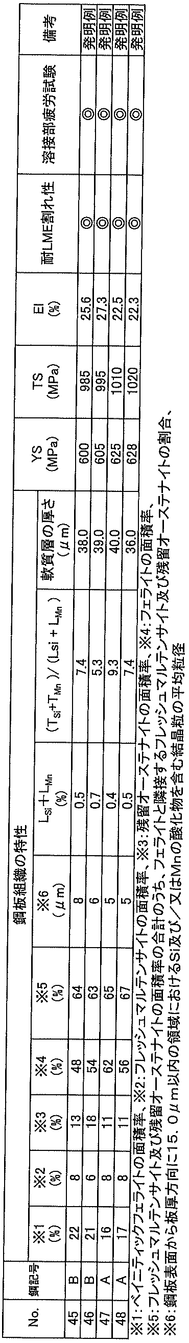
実施例3の表4の製造条件No.45(本発明例)に対して、亜鉛めっき処理を行った亜鉛めっき鋼板をプレス成形して、本発明例の部材を製造した。さらに、実施例3の表4の製造条件No.45(本発明例)に対して亜鉛めっき処理を行った亜鉛めっき鋼板と、実施例3の表4の製造条件No.47(本発明例)に対して亜鉛めっき処理を行った亜鉛めっき鋼板とをスポット溶接により接合して本発明例の部材を製造した。これら本発明例の部材は、上述した耐LME割れ性が評価「◎」と優れており、かつ、前記の部材から採取した十字引張試験片による溶接部疲労試験の評価も「◎」と優れているので、これらの部材は、自動車部品等に好適に用いられることがわかる。
Claims (26)
- 質量%で、Si:0.3%以上2.0%以下、Mn:1.0%以上2.70%未満を含有する成分組成と、
ベイニティックフェライトの面積率が10~35%、フレッシュマルテンサイトの面積率が2~15%、残留オーステナイトの面積率が5~20%、フェライトの面積率が45~70%である鋼組織と、を有し、
前記フレッシュマルテンサイト及び前記残留オーステナイトの面積率の合計のうち、フェライトと隣接する前記フレッシュマルテンサイト及び前記残留オーステナイトの割合が合計で90%以下であり、
鋼板表面から板厚方向に4.9μm以内の領域におけるSi及び/又はMnの酸化物を含む結晶粒の平均粒径が3~10μmであり、
鋼板表面から板厚方向に4.9μm以内の領域における最小のSi濃度LSi及び最小のMn濃度LMnと、鋼板の板厚1/4位置におけるSi濃度TSi及びMn濃度TMnとが、下記式(1)を満たし、
引張強さ(TS)が780MPa以上1180MPa未満である鋼板。
LSi+LMn≦(TSi+TMn)/4・・・(1) - 前記成分組成が、さらに、質量%で、
C:0.12%以上0.40%以下、
P:0.05%以下、
S:0.02%以下、
Al:0.01%以上2.0%以下、
N:0.01%以下、を含有し、残部がFe及び不可避的不純物からなる請求項1に記載の鋼板。 - 前記成分組成が、さらに、質量%で、Nb:0.50%以下、Cr:1.0%以下、Mo:0.50%以下、B:0.005%以下、及びTi:0.05%以下のうち少なくとも1種を含有する請求項2に記載の鋼板。
- 前記成分組成が、さらに、質量%で、Cu、Ni、Sn、As、Sb、Ca、Mg、Pb、Co、Ta、W、REM、Zn、V、Sr、Cs、Hf、Zrのうち少なくとも1種を合計で0.1%以下含有する請求項2又は3に記載の鋼板。
- 鋼板表面から板厚1/4位置における硬度に対して65%以下の硬度の領域のことを軟質層としたとき、
鋼板表面から板厚方向に厚さ1.0μm以上50.0μm以下の前記軟質層を有する請求項1~4のいずれか一項に記載の鋼板。 - 鋼板表面に溶融亜鉛めっき層又は合金化溶融亜鉛めっき層を有する請求項1~5のいずれか一項に記載の鋼板。
- 前記成分組成の炭素当量Ceqが0.458%以上0.659%未満である請求項1~6のいずれか一項に記載の鋼板。
- 請求項1~7のいずれか一項に記載の鋼板に対して、成形加工及び溶接の少なくとも一方を施してなる部材。
- 請求項1~4のいずれか一項に記載の成分組成を有する鋼スラブに対して、最終2段の圧延における累積歪みが0.10~0.80である熱間圧延を施した後、巻取温度:470~800℃で巻き取る熱延工程と、
前記熱延工程で得られた熱延鋼板に対して冷間圧延を施す冷延工程と、
前記冷延工程で得られた冷延鋼板を、露点:-50~0℃、かつ焼鈍温度:750~900℃の条件で保持した後、150~340℃の冷却停止温度まで冷却し、該焼鈍温度から冷却停止温度までの冷却時に半径100mm以上1000mm以下のロールで曲げ及び曲げ戻しを合計3回以上8回以下行う焼鈍工程と、
焼鈍工程後の鋼板を、350~600℃の温度域まで再加熱して保持する再加熱工程を有する鋼板の製造方法。 - 前記再加熱工程後の鋼板に対して、溶融亜鉛めっき又は合金化溶融亜鉛めっきを施すめっき工程を有する請求項9に記載の鋼板の製造方法。
- 請求項1~4のいずれか一項に記載の成分組成を有する鋼スラブに対して、最終2段の圧延における累積歪みが0.10~0.80である熱間圧延を施した後、巻取温度:470~800℃で巻き取る熱延工程と、
前記熱延工程で得られた熱延鋼板に対して冷間圧延を施す冷延工程と、
前記冷延工程で得られた冷延鋼板を、露点:-50~0℃、かつ焼鈍温度:750~900℃の条件で保持した後、350~500℃の冷却停止温度まで冷却し、該焼鈍温度から冷却停止温度までの冷却時に半径100mm以上1000mm以下のロールで曲げ及び曲げ戻しを合計3回以上8回以下行う焼鈍工程と、
前記焼鈍工程後の鋼板に対して、溶融亜鉛めっき又は合金化溶融亜鉛めっきを施すめっき工程と、
前記めっき工程後の鋼板を50℃以上350℃以下の冷却停止温度まで冷却した後、該冷却停止温度超かつ300℃以上500℃以下の温度まで再加熱して保持する再加熱工程と、を有する鋼板の製造方法。 - 前記成分組成の炭素当量Ceqが0.458%以上0.659%未満である請求項9~11のいずれか一項に記載の鋼板の製造方法。
- 請求項9~12のいずれか一項に記載の鋼板の製造方法によって製造された鋼板に対して、成形加工及び溶接の少なくとも一方を施す工程を有する部材の製造方法。
- 質量%で、Si:0.3%以上2.0%以下、Mn:1.0%以上2.70%未満を含有する成分組成と、
ベイニティックフェライトの面積率が10~35%、フレッシュマルテンサイトの面積率が2~15%、残留オーステナイトの面積率が5~20%、フェライトの面積率が45~70%である鋼組織と、を有し、
前記フレッシュマルテンサイト及び前記残留オーステナイトの面積率の合計のうち、フェライトと隣接する前記フレッシュマルテンサイト及び前記残留オーステナイトの割合が合計で90%以下であり、
鋼板表面から板厚方向に15.0μm以内の領域におけるSi及び/又はMnの酸化物を含む結晶粒の平均粒径が3~10μmであり、
鋼板表面から板厚方向に15.0μm以内の領域における最小のSi濃度LSi及び最小のMn濃度LMnと、鋼板の板厚1/4位置におけるSi濃度TSi及びMn濃度TMnとが、下記式(1)を満たし、
引張強さ(TS)が780MPa以上1180MPa未満である鋼板。
LSi+LMn≦(TSi+TMn)/4・・・(1) - 前記成分組成が、さらに、質量%で、
C:0.12%以上0.40%以下、
P:0.05%以下、
S:0.02%以下、
Al:0.01%以上2.0%以下、
N:0.01%以下、を含有し、残部がFe及び不可避的不純物からなる請求項14に記載の鋼板。 - 前記成分組成が、さらに、質量%で、Nb:0.50%以下、Cr:1.0%以下、Mo:0.50%以下、B:0.005%以下、及びTi:0.05%以下のうち少なくとも1種を含有する請求項15に記載の鋼板。
- 前記成分組成が、さらに、質量%で、Cu、Ni、Sn、As、Sb、Ca、Mg、Pb、Co、Ta、W、REM、Zn、V、Sr、Cs、Hf、Zrのうち少なくとも1種を合計で0.1%以下含有する請求項15又は16に記載の鋼板。
- 鋼板表面から板厚1/4位置における硬度に対して65%以下の硬度の領域のことを軟質層としたとき、
鋼板表面から板厚方向に厚さ1.0μm以上50.0μm以下の前記軟質層を有する請求項14~17のいずれか一項に記載の鋼板。 - 鋼板表面に溶融亜鉛めっき層又は合金化溶融亜鉛めっき層を有する請求項14~18のいずれか一項に記載の鋼板。
- 前記成分組成の炭素当量Ceqが0.458%以上0.659%未満である請求項14~19のいずれか一項に記載の鋼板。
- 請求項14~20のいずれか一項に記載の鋼板に対して、成形加工及び溶接の少なくとも一方を施してなる部材。
- 請求項14~17のいずれか一項に記載の成分組成を有する鋼スラブに対して、最終2段の圧延における累積歪みが0.10~0.80である熱間圧延を施した後、巻取温度:470~800℃で巻き取る熱延工程と、
前記熱延工程で得られた熱延鋼板に対して冷間圧延を施す冷延工程と、
前記冷延工程で得られた冷延鋼板を、露点:-50~20℃、かつ焼鈍温度:750~900℃の条件で保持した後、150~340℃の冷却停止温度まで冷却し、該焼鈍温度から冷却停止温度までの冷却時に半径100mm以上1000mm以下のロールで曲げ及び曲げ戻しを合計3回以上8回以下行う焼鈍工程と、
焼鈍工程後の鋼板を、350~600℃の温度域まで再加熱して保持する再加熱工程を有する鋼板の製造方法。 - 前記再加熱工程後の鋼板に対して、溶融亜鉛めっき又は合金化溶融亜鉛めっきを施すめっき工程を有する請求項22に記載の鋼板の製造方法。
- 請求項14~17のいずれか一項に記載の成分組成を有する鋼スラブに対して、最終2段の圧延における累積歪みが0.10~0.80である熱間圧延を施した後、巻取温度:470~800℃で巻き取る熱延工程と、
前記熱延工程で得られた熱延鋼板に対して冷間圧延を施す冷延工程と、
前記冷延工程で得られた冷延鋼板を、露点:-50~20℃、かつ焼鈍温度:750~900℃の条件で保持した後、350~500℃の冷却停止温度まで冷却し、該焼鈍温度から冷却停止温度までの冷却時に半径100mm以上1000mm以下のロールで曲げ及び曲げ戻しを合計3回以上8回以下行う焼鈍工程と、
前記焼鈍工程後の鋼板に対して、溶融亜鉛めっき又は合金化溶融亜鉛めっきを施すめっき工程と、
前記めっき工程後の鋼板を50℃以上350℃以下の冷却停止温度まで冷却した後、該冷却停止温度超かつ300℃以上500℃以下の温度まで再加熱して保持する再加熱工程と、を有する鋼板の製造方法。 - 前記成分組成の炭素当量Ceqが0.458%以上0.659%未満である請求項22~24のいずれか一項に記載の鋼板の製造方法。
- 請求項22~25のいずれか一項に記載の鋼板の製造方法によって製造された鋼板に対して、成形加工及び溶接の少なくとも一方を施す工程を有する部材の製造方法。
Priority Applications (8)
| Application Number | Priority Date | Filing Date | Title |
|---|---|---|---|
| JP2021535766A JP7001205B1 (ja) | 2020-03-31 | 2021-03-25 | 鋼板及び部材 |
| EP21781061.3A EP4130326A4 (en) | 2020-03-31 | 2021-03-25 | STEEL SHEET, ELEMENT, AND METHODS OF MAKING THE SAME |
| KR1020227033051A KR20220144404A (ko) | 2020-03-31 | 2021-03-25 | 강판, 부재 및 그들의 제조 방법 |
| CN202180025265.5A CN115362275B (zh) | 2020-03-31 | 2021-03-25 | 钢板、部件及其制造方法 |
| US17/915,696 US20230160032A1 (en) | 2020-03-31 | 2021-03-25 | Steel sheet, member, and method for producing them |
| MX2022012141A MX2022012141A (es) | 2020-03-31 | 2021-03-25 | Chapa de acero, miembro, y metodo para producirlos. |
| JP2021160513A JP2022023084A (ja) | 2020-03-31 | 2021-09-30 | 鋼板、部材及びそれらの製造方法 |
| JP2021193112A JP7044195B2 (ja) | 2020-03-31 | 2021-11-29 | 鋼板の製造方法及び部材の製造方法 |
Applications Claiming Priority (4)
| Application Number | Priority Date | Filing Date | Title |
|---|---|---|---|
| JP2020062955 | 2020-03-31 | ||
| JP2020-062955 | 2020-03-31 | ||
| JP2020-122181 | 2020-07-16 | ||
| JP2020122181 | 2020-07-16 |
Publications (1)
| Publication Number | Publication Date |
|---|---|
| WO2021200577A1 true WO2021200577A1 (ja) | 2021-10-07 |
Family
ID=77929355
Family Applications (1)
| Application Number | Title | Priority Date | Filing Date |
|---|---|---|---|
| PCT/JP2021/012659 WO2021200577A1 (ja) | 2020-03-31 | 2021-03-25 | 鋼板、部材及びそれらの製造方法 |
Country Status (7)
| Country | Link |
|---|---|
| US (1) | US20230160032A1 (ja) |
| EP (1) | EP4130326A4 (ja) |
| JP (3) | JP7001205B1 (ja) |
| KR (1) | KR20220144404A (ja) |
| CN (1) | CN115362275B (ja) |
| MX (1) | MX2022012141A (ja) |
| WO (1) | WO2021200577A1 (ja) |
Cited By (1)
| Publication number | Priority date | Publication date | Assignee | Title |
|---|---|---|---|---|
| WO2023063097A1 (ja) * | 2021-10-12 | 2023-04-20 | Jfeスチール株式会社 | 抵抗スポット溶接継手およびその抵抗スポット溶接方法 |
Citations (8)
| Publication number | Priority date | Publication date | Assignee | Title |
|---|---|---|---|---|
| JP2006265671A (ja) | 2005-03-25 | 2006-10-05 | Nisshin Steel Co Ltd | 加工性及び耐溶融金属脆化割れ性に優れた合金化溶融亜鉛めっき高張力鋼板 |
| JP4943558B2 (ja) | 2009-08-31 | 2012-05-30 | 新日本製鐵株式会社 | 高強度溶融亜鉛めっき鋼板及びその製造方法 |
| WO2015092982A1 (ja) * | 2013-12-18 | 2015-06-25 | Jfeスチール株式会社 | 高強度鋼板およびその製造方法 |
| JP2017002384A (ja) * | 2015-06-15 | 2017-01-05 | 新日鐵住金株式会社 | 耐スポット溶接部破断特性に優れた鋼板及びその製造方法 |
| WO2019026113A1 (ja) * | 2017-07-31 | 2019-02-07 | 新日鐵住金株式会社 | 溶融亜鉛めっき鋼板 |
| JP2019504196A (ja) * | 2015-12-15 | 2019-02-14 | ポスコPosco | 表面品質及びスポット溶接性に優れた高強度溶融亜鉛めっき鋼板及びその製造方法 |
| WO2019077777A1 (ja) * | 2017-10-20 | 2019-04-25 | Jfeスチール株式会社 | 高強度鋼板およびその製造方法 |
| WO2020158066A1 (ja) * | 2019-01-30 | 2020-08-06 | Jfeスチール株式会社 | 高強度鋼板およびその製造方法 |
Family Cites Families (13)
| Publication number | Priority date | Publication date | Assignee | Title |
|---|---|---|---|---|
| JPS4943558B1 (ja) | 1970-02-14 | 1974-11-21 | ||
| JP4164537B2 (ja) * | 2006-12-11 | 2008-10-15 | 株式会社神戸製鋼所 | 高強度薄鋼板 |
| JP5699764B2 (ja) * | 2011-04-11 | 2015-04-15 | 新日鐵住金株式会社 | 合金化溶融亜鉛めっき鋼板およびその製造方法 |
| JP5632947B2 (ja) * | 2012-12-12 | 2014-11-26 | 株式会社神戸製鋼所 | 加工性と低温靭性に優れた高強度鋼板およびその製造方法 |
| JP6007882B2 (ja) * | 2013-10-15 | 2016-10-19 | 新日鐵住金株式会社 | 引張最大強度780MPaを有する衝突特性に優れた高強度鋼板、高強度溶融亜鉛めっき鋼板、並びに、高強度合金化溶融亜鉛めっき鋼板 |
| WO2016111273A1 (ja) * | 2015-01-09 | 2016-07-14 | 株式会社神戸製鋼所 | 高強度めっき鋼板、並びにその製造方法 |
| WO2016121388A1 (ja) * | 2015-01-28 | 2016-08-04 | Jfeスチール株式会社 | 高強度冷延鋼板、高強度めっき鋼板及びこれらの製造方法 |
| US10745775B2 (en) * | 2015-06-11 | 2020-08-18 | Nippon Steel Corporation | Galvannealed steel sheet and method for producing the same |
| JP2017066508A (ja) * | 2015-10-02 | 2017-04-06 | 株式会社神戸製鋼所 | 熱間プレス用亜鉛めっき鋼板および熱間プレス成形品の製造方法 |
| WO2018088421A1 (ja) * | 2016-11-10 | 2018-05-17 | Jfeスチール株式会社 | 高強度冷延薄鋼板および高強度冷延薄鋼板の製造方法 |
| JP6414246B2 (ja) * | 2017-02-15 | 2018-10-31 | Jfeスチール株式会社 | 高強度鋼板およびその製造方法 |
| JP6428970B1 (ja) * | 2017-03-30 | 2018-11-28 | Jfeスチール株式会社 | ホットプレス部材およびその製造方法 |
| WO2018186335A1 (ja) * | 2017-04-05 | 2018-10-11 | Jfeスチール株式会社 | 高強度冷延鋼板およびその製造方法 |
-
2021
- 2021-03-25 WO PCT/JP2021/012659 patent/WO2021200577A1/ja unknown
- 2021-03-25 JP JP2021535766A patent/JP7001205B1/ja active Active
- 2021-03-25 EP EP21781061.3A patent/EP4130326A4/en active Pending
- 2021-03-25 CN CN202180025265.5A patent/CN115362275B/zh active Active
- 2021-03-25 MX MX2022012141A patent/MX2022012141A/es unknown
- 2021-03-25 KR KR1020227033051A patent/KR20220144404A/ko unknown
- 2021-03-25 US US17/915,696 patent/US20230160032A1/en active Pending
- 2021-09-30 JP JP2021160513A patent/JP2022023084A/ja active Pending
- 2021-11-29 JP JP2021193112A patent/JP7044195B2/ja active Active
Patent Citations (8)
| Publication number | Priority date | Publication date | Assignee | Title |
|---|---|---|---|---|
| JP2006265671A (ja) | 2005-03-25 | 2006-10-05 | Nisshin Steel Co Ltd | 加工性及び耐溶融金属脆化割れ性に優れた合金化溶融亜鉛めっき高張力鋼板 |
| JP4943558B2 (ja) | 2009-08-31 | 2012-05-30 | 新日本製鐵株式会社 | 高強度溶融亜鉛めっき鋼板及びその製造方法 |
| WO2015092982A1 (ja) * | 2013-12-18 | 2015-06-25 | Jfeスチール株式会社 | 高強度鋼板およびその製造方法 |
| JP2017002384A (ja) * | 2015-06-15 | 2017-01-05 | 新日鐵住金株式会社 | 耐スポット溶接部破断特性に優れた鋼板及びその製造方法 |
| JP2019504196A (ja) * | 2015-12-15 | 2019-02-14 | ポスコPosco | 表面品質及びスポット溶接性に優れた高強度溶融亜鉛めっき鋼板及びその製造方法 |
| WO2019026113A1 (ja) * | 2017-07-31 | 2019-02-07 | 新日鐵住金株式会社 | 溶融亜鉛めっき鋼板 |
| WO2019077777A1 (ja) * | 2017-10-20 | 2019-04-25 | Jfeスチール株式会社 | 高強度鋼板およびその製造方法 |
| WO2020158066A1 (ja) * | 2019-01-30 | 2020-08-06 | Jfeスチール株式会社 | 高強度鋼板およびその製造方法 |
Non-Patent Citations (1)
| Title |
|---|
| See also references of EP4130326A4 |
Cited By (1)
| Publication number | Priority date | Publication date | Assignee | Title |
|---|---|---|---|---|
| WO2023063097A1 (ja) * | 2021-10-12 | 2023-04-20 | Jfeスチール株式会社 | 抵抗スポット溶接継手およびその抵抗スポット溶接方法 |
Also Published As
| Publication number | Publication date |
|---|---|
| CN115362275B (zh) | 2024-03-01 |
| JPWO2021200577A1 (ja) | 2021-10-07 |
| JP2022023084A (ja) | 2022-02-07 |
| MX2022012141A (es) | 2022-10-18 |
| JP7001205B1 (ja) | 2022-02-03 |
| KR20220144404A (ko) | 2022-10-26 |
| JP7044195B2 (ja) | 2022-03-30 |
| CN115362275A (zh) | 2022-11-18 |
| JP2022024144A (ja) | 2022-02-08 |
| EP4130326A4 (en) | 2023-08-30 |
| US20230160032A1 (en) | 2023-05-25 |
| EP4130326A1 (en) | 2023-02-08 |
Similar Documents
| Publication | Publication Date | Title |
|---|---|---|
| US10329638B2 (en) | High strength galvanized steel sheet and production method therefor | |
| EP2743364A1 (en) | Hot-rolled steel sheet having high yield ratio and excellent low-temperature impact energy absorption and haz softening resistance and method for producing same | |
| WO2019003541A1 (ja) | 熱間プレス部材およびその製造方法ならびに熱間プレス用冷延鋼板およびその製造方法 | |
| JP6787523B1 (ja) | 高強度鋼板およびその製造方法 | |
| JP6787535B1 (ja) | 高強度鋼板およびその製造方法 | |
| EP3653745A1 (en) | High-strength steel sheet and manufacturing method thereof | |
| JP7276618B2 (ja) | 高強度冷延鋼板およびその製造方法 | |
| JP7044196B2 (ja) | 鋼板の製造方法及び部材の製造方法 | |
| CN114207169A (zh) | 钢板及其制造方法 | |
| JP7276614B2 (ja) | 自動車用部材およびその抵抗スポット溶接方法 | |
| KR102153194B1 (ko) | 액상금속취화(lme) 균열 저항성이 우수한 초고강도 고연성 냉연강판, 도금강판 및 이들의 제조방법 | |
| JP7044195B2 (ja) | 鋼板の製造方法及び部材の製造方法 | |
| JP7311808B2 (ja) | 鋼板及びその製造方法 | |
| EP3964598B1 (en) | Steel sheet | |
| WO2022249919A1 (ja) | 高強度合金化溶融亜鉛めっき鋼板およびその製造方法 | |
| JP2022182938A (ja) | 高強度合金化溶融亜鉛めっき鋼板およびその製造方法 |
Legal Events
| Date | Code | Title | Description |
|---|---|---|---|
| ENP | Entry into the national phase |
Ref document number: 2021535766 Country of ref document: JP Kind code of ref document: A |
|
| 121 | Ep: the epo has been informed by wipo that ep was designated in this application |
Ref document number: 21781061 Country of ref document: EP Kind code of ref document: A1 |
|
| ENP | Entry into the national phase |
Ref document number: 20227033051 Country of ref document: KR Kind code of ref document: A |
|
| NENP | Non-entry into the national phase |
Ref country code: DE |
|
| ENP | Entry into the national phase |
Ref document number: 2021781061 Country of ref document: EP Effective date: 20221031 |