WO2021200537A1 - モータユニット及び電気自動車 - Google Patents
モータユニット及び電気自動車 Download PDFInfo
- Publication number
- WO2021200537A1 WO2021200537A1 PCT/JP2021/012536 JP2021012536W WO2021200537A1 WO 2021200537 A1 WO2021200537 A1 WO 2021200537A1 JP 2021012536 W JP2021012536 W JP 2021012536W WO 2021200537 A1 WO2021200537 A1 WO 2021200537A1
- Authority
- WO
- WIPO (PCT)
- Prior art keywords
- housing
- flow path
- motor
- motor unit
- unit according
- Prior art date
- Legal status (The legal status is an assumption and is not a legal conclusion. Google has not performed a legal analysis and makes no representation as to the accuracy of the status listed.)
- Ceased
Links
Images






Classifications
-
- B—PERFORMING OPERATIONS; TRANSPORTING
- B60—VEHICLES IN GENERAL
- B60K—ARRANGEMENT OR MOUNTING OF PROPULSION UNITS OR OF TRANSMISSIONS IN VEHICLES; ARRANGEMENT OR MOUNTING OF PLURAL DIVERSE PRIME-MOVERS IN VEHICLES; AUXILIARY DRIVES FOR VEHICLES; INSTRUMENTATION OR DASHBOARDS FOR VEHICLES; ARRANGEMENTS IN CONNECTION WITH COOLING, AIR INTAKE, GAS EXHAUST OR FUEL SUPPLY OF PROPULSION UNITS IN VEHICLES
- B60K17/00—Arrangement or mounting of transmissions in vehicles
- B60K17/04—Arrangement or mounting of transmissions in vehicles characterised by arrangement, location or kind of gearing
- B60K17/12—Arrangement or mounting of transmissions in vehicles characterised by arrangement, location or kind of gearing of electric gearing
-
- B—PERFORMING OPERATIONS; TRANSPORTING
- B60—VEHICLES IN GENERAL
- B60L—PROPULSION OF ELECTRICALLY-PROPELLED VEHICLES; SUPPLYING ELECTRIC POWER FOR AUXILIARY EQUIPMENT OF ELECTRICALLY-PROPELLED VEHICLES; ELECTRODYNAMIC BRAKE SYSTEMS FOR VEHICLES IN GENERAL; MAGNETIC SUSPENSION OR LEVITATION FOR VEHICLES; MONITORING OPERATING VARIABLES OF ELECTRICALLY-PROPELLED VEHICLES; ELECTRIC SAFETY DEVICES FOR ELECTRICALLY-PROPELLED VEHICLES
- B60L3/00—Electric devices on electrically-propelled vehicles for safety purposes; Monitoring operating variables, e.g. speed, deceleration or energy consumption
-
- F—MECHANICAL ENGINEERING; LIGHTING; HEATING; WEAPONS; BLASTING
- F16—ENGINEERING ELEMENTS AND UNITS; GENERAL MEASURES FOR PRODUCING AND MAINTAINING EFFECTIVE FUNCTIONING OF MACHINES OR INSTALLATIONS; THERMAL INSULATION IN GENERAL
- F16H—GEARING
- F16H57/00—General details of gearing
- F16H57/04—Features relating to lubrication or cooling or heating
-
- H—ELECTRICITY
- H02—GENERATION; CONVERSION OR DISTRIBUTION OF ELECTRIC POWER
- H02K—DYNAMO-ELECTRIC MACHINES
- H02K9/00—Arrangements for cooling or ventilating
- H02K9/19—Arrangements for cooling or ventilating for machines with closed casing and closed-circuit cooling using a liquid cooling medium, e.g. oil
-
- Y—GENERAL TAGGING OF NEW TECHNOLOGICAL DEVELOPMENTS; GENERAL TAGGING OF CROSS-SECTIONAL TECHNOLOGIES SPANNING OVER SEVERAL SECTIONS OF THE IPC; TECHNICAL SUBJECTS COVERED BY FORMER USPC CROSS-REFERENCE ART COLLECTIONS [XRACs] AND DIGESTS
- Y02—TECHNOLOGIES OR APPLICATIONS FOR MITIGATION OR ADAPTATION AGAINST CLIMATE CHANGE
- Y02T—CLIMATE CHANGE MITIGATION TECHNOLOGIES RELATED TO TRANSPORTATION
- Y02T10/00—Road transport of goods or passengers
- Y02T10/60—Other road transportation technologies with climate change mitigation effect
- Y02T10/64—Electric machine technologies in electromobility
-
- Y—GENERAL TAGGING OF NEW TECHNOLOGICAL DEVELOPMENTS; GENERAL TAGGING OF CROSS-SECTIONAL TECHNOLOGIES SPANNING OVER SEVERAL SECTIONS OF THE IPC; TECHNICAL SUBJECTS COVERED BY FORMER USPC CROSS-REFERENCE ART COLLECTIONS [XRACs] AND DIGESTS
- Y02—TECHNOLOGIES OR APPLICATIONS FOR MITIGATION OR ADAPTATION AGAINST CLIMATE CHANGE
- Y02T—CLIMATE CHANGE MITIGATION TECHNOLOGIES RELATED TO TRANSPORTATION
- Y02T90/00—Enabling technologies or technologies with a potential or indirect contribution to GHG emissions mitigation
- Y02T90/10—Technologies relating to charging of electric vehicles
- Y02T90/16—Information or communication technologies improving the operation of electric vehicles
Definitions
- the present invention relates to a motor unit and an electric vehicle.
- the conventional motor unit is mounted on a vehicle body and includes a first housing (motor housing), a second housing (gear housing), and a partition wall that separates the first housing and the second housing.
- the first housing houses a motor having a rotor that rotates about a motor shaft.
- a through hole (communication port) is formed in the partition wall.
- the cooling medium (oil) that has cooled the motor flows from the first housing to the second housing through the through holes (see, for example, Japanese Patent Application Laid-Open No. 2016-208722).
- oil may not smoothly flow to the partition wall side due to the left and right shaking and tilting of the vehicle body, and may stay in the first housing.
- the rotor rotates, there is a problem that the loss due to stirring of the retained cooling medium becomes large, the rotation resistance of the rotor increases, and the driving efficiency of the motor unit decreases.
- An object of the present invention is to provide a motor unit capable of reducing a decrease in drive efficiency and an electric vehicle provided with the motor unit.
- An exemplary motor unit of the present invention includes a motor and a housing.
- the motor has a rotor and a stator.
- the rotor rotates about the motor shaft.
- the stator faces radially outwardly through a gap with the rotor.
- the housing is cylindrical and has a first housing, a second housing, and a partition wall.
- the first housing houses the motor.
- the second housing is arranged adjacent to the motor chamber and stores a cooling medium for cooling the motor.
- the partition wall partitions the first housing and the second housing, and is formed so as to project radially inward from the inner peripheral surface.
- the partition wall has a through hole that communicates the inside of the first housing with the inside of the second housing and guides the cooling medium from the first housing to the second housing.
- the housing has a bypass flow path through which the cooling medium communicates.
- the bypass flow path is arranged outside the first housing and the second housing, and communicates the inflow port facing the inside of the first housing and the outlet opening facing
- a motor unit capable of reducing a decrease in drive efficiency and an electric vehicle including the motor unit.
- FIG. 1 is a schematic configuration diagram schematically showing an electric vehicle including a motor unit according to the first embodiment of the present invention.
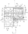
- FIG. 2 is a schematic configuration diagram schematically showing an internal configuration of a motor unit according to the first embodiment of the present invention.
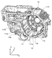
- FIG. 3 is a perspective view of the housing of the motor unit according to the first embodiment of the present invention.
- FIG. 4 is a perspective view of the housing of the motor unit according to the first embodiment of the present invention.
- FIG. 5 is a side view of the housing of the motor unit according to the first embodiment of the present invention.
- FIG. 6 is a schematic configuration diagram schematically showing an internal configuration of a motor unit according to a second embodiment of the present invention.
- FIG. 7 is a side view of the housing of the motor unit according to the third embodiment of the present invention.
- FIG. 8 is a side view of the housing of the motor unit according to the fourth embodiment of the present invention.
- FIG. 9 is a perspective view of the housing of the motor unit according to the fifth embodiment of the present invention.
- FIG. 10 is a schematic configuration diagram schematically showing an internal configuration of a motor unit according to a sixth embodiment of the present invention.
- FIG. 11 is a schematic configuration diagram schematically showing an internal configuration of a motor unit according to a seventh embodiment of the present invention.
- FIG. 12 is a schematic configuration diagram schematically showing an internal configuration of a motor unit according to a seventh embodiment of the present invention.
- FIG. 13 is a perspective view showing a part of the first housing of the motor unit according to the seventh embodiment of the present invention.
- FIG. 14 is a perspective view showing a part of the first housing of the motor unit according to the seventh embodiment of the present invention.
- FIG. 15 is a perspective view showing a part of the first housing of the motor unit according to the seventh embodiment of the present invention.
- the vertical direction will be defined and described based on the positional relationship when the motor unit 1 is mounted on a vehicle located on a horizontal road surface.
- the XYZ coordinate system is shown as a three-dimensional Cartesian coordinate system as appropriate.
- the Z-axis direction is a vertical direction with the + Z side as the upper side and the ⁇ Z side as the lower side.
- the X-axis direction is a direction orthogonal to the Z-axis direction and is a front-rear direction of the vehicle on which the motor unit 1 is mounted.
- the + X side is the front side of the vehicle, and the ⁇ X side is the rear side of the vehicle.
- the Y-axis direction is a direction orthogonal to both the X-axis direction and the Z-axis direction, and is the left-right direction of the vehicle.
- the + Y side is the left side of the vehicle, and the ⁇ Y side is the right side of the vehicle.
- the positional relationship in the front-rear direction is not limited to the positional relationship of the present embodiment, and the + X side may be the rear side of the vehicle and the ⁇ X side may be the front side of the vehicle.
- the + Y side is the right side of the vehicle, and the ⁇ Y side is the left side of the vehicle.
- the motor shaft J1 shown in each figure extends in the Y-axis direction, that is, in the left-right direction of the vehicle.
- the direction parallel to the motor shaft J1 is simply referred to as the "axial direction”
- the radial direction centered on the motor shaft J1 is simply referred to as the "radial direction”
- the motor shaft J1 is referred to as the motor shaft J1.
- the circumferential direction around the center, that is, the circumference of the motor shaft J1 is simply referred to as the "circumferential direction”.
- the "parallel direction” includes a substantially parallel direction
- the “orthogonal direction” also includes a substantially orthogonal direction.
- FIG. 1 is a schematic configuration diagram schematically showing an electric vehicle 100 including a motor unit 1 according to an embodiment of the present invention.
- the electric vehicle 100 includes a motor unit 1, a chassis 130, a pair of left and right drive wheels 110, and a pair of left and right driven wheels 120.
- the drive wheels 110 are rotationally driven by the motor unit 1.
- the chassis 130 constitutes the skeleton of the electric vehicle 100, and the motor unit 1 is arranged in front of the bottom of the electric vehicle 100.
- the motor unit 1 is used as a driving force source for the electric vehicle 100.
- the motor power from the motor unit 1 is transmitted to the pair of drive wheels 110 via the drive shaft DS.
- the drive shaft DS extends along the differential shaft J3 of the motor unit 1, which will be described later.
- FIG. 2 is a diagram schematically showing the internal configuration of the motor unit 1.
- the motor unit 1 includes a cylindrical housing 10, a motor 20, a transmission device 50 including a speed reducer 30 and a differential device 40, a pump 70, a cooler 75, and a pipe 78.
- the housing 10 houses the motor 20 and the transmission device 50 inside.
- the housing 10 has a first housing 11, a second housing 12, a partition wall 13, and a bypass flow path 15.
- the first housing 11, the second housing 12, the partition wall 13, and the bypass flow path 15 are formed by die casting.
- the first housing 11 surrounds the motor 20 from the outside in the radial direction and houses the motor 20.
- the first housing 11 has a cylindrical peripheral wall portion 11a extending in the axial direction and a side wall portion 11b that closes the right side of the peripheral wall portion 11a.
- the peripheral wall portion 11a faces the stator 22 described later in the radial direction.
- the second housing 12 surrounds the speed reducer 30 and the differential device 40 from the outside in the radial direction, and houses the speed reducer 30 and the differential device 40. That is, the transmission device 50 is housed in the second housing 12.
- the second housing 12 has a cylindrical peripheral wall portion 12a extending in the axial direction, and a side wall portion 12b that closes the left side of the peripheral wall portion 12a.
- the second housing 12 is arranged adjacent to the first housing 11.
- the bottom portion inside the second housing 12 is located at least in part below the bottom portion inside the first housing 11.
- the partition wall 13 is formed by partitioning the first housing 11 and the second housing 12 and projecting inward in the radial direction from the inner peripheral surface of the housing 10.
- the partition wall 13 holds a bearing 24, which will be described later.
- the partition wall 13 has a through hole 13a for communicating the inside of the first housing 11 and the inside of the second housing 12.
- the through hole 13a is provided at the lower end of the partition wall 13.
- the bypass flow path 15 is arranged outside the first housing 11 and the second housing 12, and the inflow port 15a opens at one end and the outflow port 15b opens at the other end.
- the inflow port 15a is arranged on the peripheral wall portion 11a and opens toward the inside of the first housing 11.
- the outlet 15b opens facing the inside of the second housing 12.
- the inflow port 15a is arranged in the lower part of the first housing 11, and the outflow port 15b is arranged in the lower part of the second housing 12.
- the housing 10 houses oil (cooling medium) O as a refrigerant inside.
- An oil reservoir P in which the oil O is accumulated is provided in the lower region inside the second housing 12. That is, the second housing 12 stores the oil O (cooling medium) that cools the motor.
- the through hole 13a guides the oil O from the first housing 11 to the second housing 12. Further, oil O flows through the bypass flow path 15.
- the oil O in the oil sump P is sent to the inside of the first housing 11 by the oil passage 90 described later.
- the oil O sent to the inside of the first housing 11 collects in the lower region inside the first housing 11. At least a part of the oil O accumulated inside the first housing 11 flows to the second housing 12 through the through hole 13a and the bypass flow path 15, and returns to the oil reservoir P.
- the bypass flow path 15 By providing the bypass flow path 15 in addition to the through hole 13a, the oil O in the first housing 11 can easily flow to the second housing 12.
- Oil O is a cooling medium for cooling the motor 20, and circulates in the oil passage 90 described later. Oil O is used for lubricating the speed reducer 30 and the differential device 40. As the oil O, it is preferable to use an oil equivalent to the lubricating oil for automatic transmission (ATF: Automatic Transmission Fluid) having a relatively low viscosity in order to perform the functions of the lubricating oil and the cooling oil.
- ATF Automatic Transmission Fluid
- the motor 20 is an inner rotor type motor.
- the motor 20 includes a rotor 21, a stator 22, and bearings 23, 24, and 25.
- the rotor 21 rotates about a motor shaft J1 extending in the horizontal direction.
- the rotor 21 has a shaft 211 and a rotor body 212.
- the rotor main body 212 has a rotor core (not shown) and a rotor magnet (not shown) fixed to the rotor core. The torque of the rotor 21 is transmitted to the transmission device 50.
- the shaft 211 extends along the axial direction with the motor shaft J1 as the center.
- the shaft 211 rotates about the motor shaft J1.
- the shaft 211 is a hollow shaft provided with a hollow portion 211a inside.
- the shaft 211 is provided with a communication hole 211b.
- the communication hole 211b communicates the hollow portion 211a with the outside of the shaft 211.
- the shaft 211 extends across the inside of the first housing 11 and the inside of the second housing 12.
- a first gear 31, which will be described later, of the speed reducer 30 is fixed to the left end of the shaft 211.
- the shaft 211 is rotatably supported by bearings 23, 24, 25.
- Bearings 23, 24 and 25 are, for example, ball bearings.
- the bearing 23 is held by the side wall portion 11b.
- the bearing 24 is held by the partition wall 13.
- the bearing 25 is held by the side wall portion 12b.
- the stator 22 faces the rotor 21 outward in the radial direction through a gap.
- the stator 22 has a stator core 221 and a plurality of coils 222.
- the stator core 221 surrounds the rotor 21.
- the stator core 221 has a cylindrical core back (not shown) extending in the axial direction and a plurality of teeth (not shown) extending radially inward from the core back. The plurality of teeth are arranged at equal intervals along the circumferential direction.
- the plurality of coils 222 are attached to each tooth of the stator core 221 via an insulator (not shown).
- the plurality of coils 222 are arranged along the circumferential direction.
- Transmission device configuration The torque output from the motor 20 is transmitted to the differential device 40 via the speed reducer 30.
- the speed reducer 30 is connected to the motor 20. That is, the transmission device 50 is connected to the motor 20.
- the speed reduction device 30 reduces the rotation speed of the motor 20 and increases the torque output from the motor 20 according to the reduction ratio.
- the speed reducing device 30 transmits the torque output from the motor 20 to the differential device 40.
- the reduction gear 30 includes a first gear 31, a second gear 32, a third gear 33, and an intermediate shaft 35.
- the first gear 31 is fixed to the outer peripheral surface at the left end of the shaft 211.
- the first gear 31 rotates about the motor shaft J1 together with the shaft 211.
- the intermediate shaft 35 extends along an intermediate shaft J2 parallel to the motor shaft J1.
- the intermediate shaft 35 rotates about the intermediate shaft J2.
- the second gear 32 and the third gear 33 are fixed to the outer peripheral surface of the intermediate shaft 35.
- the second gear 32 and the third gear 33 are connected via the intermediate shaft 35 and rotate about the intermediate shaft J2.
- the second gear 32 meshes with the first gear 31.
- the third gear 33 meshes with the ring gear 41 described later of the differential device 40.
- the torque output from the motor 20 is transmitted to the ring gear 41 of the differential device 40 via the shaft 211, the first gear 31, the second gear 32, the intermediate shaft 35, and the third gear 33 in this order.
- the gear ratio of each gear, the number of gears, and the like can be variously changed according to the required reduction ratio.
- the speed reducer 30 is a parallel shaft gear type speed reducer in which the shaft cores of the gears are arranged in parallel.
- the differential device 40 is connected to the motor 20 via the speed reducer 30.
- the differential device 40 transmits the torque output from the motor 20 to the wheels of the vehicle.
- the differential device 40 transmits the same torque to the drive shafts DS of both the left and right wheels while absorbing the speed difference between the left and right drive wheels 110 when the electric vehicle 100 turns.
- the differential device 40 includes a ring gear 41, a gear housing (not shown), a pair of pinion gears (not shown), a pinion shaft (not shown), and a pair of side gears (not shown).
- the ring gear 41 rotates about a differential shaft J3 parallel to the motor shaft J1.
- the torque output from the motor 20 is transmitted to the ring gear 41 via the speed reducer 30.
- Oil channel configuration The motor 20 is provided with an oil passage 90 in which the oil O circulates inside the housing 10.
- the oil passage 90 is a path of the oil O that supplies the oil O from the oil sump P to the motor 20 and leads the oil O to the oil sump P again.
- the oil passage 90 is provided so as to straddle the inside of the first housing 11 and the inside of the second housing 12.
- the "oil passage” means the route of oil O. Therefore, the “oil passage” is a concept that includes not only a “flow path” that constantly creates a flow of oil O in one direction, but also a path for temporarily retaining oil O and a path for oil O to drip. Is.
- the path for temporarily retaining the oil O includes, for example, a reservoir for storing the oil O.
- the oil passage 90 has a first oil passage 91 and a second oil passage 92.
- the first oil passage 91 and the second oil passage 92 circulate the oil O inside the housing 10, respectively.
- the first oil passage 91 has a pumping path 91a, a shaft supply path 91b, an in-shaft path 91c, and an in-rotor path 91d. Further, a first reservoir 93 is provided in the path of the first oil passage 91. The first reservoir 93 is provided in the second housing 12.
- the scooping path 91a is a path in which the oil O is scooped up from the oil sump P by the rotation of the ring gear 41 of the differential device 40, and the oil O is received in the first reservoir 93.
- the first reservoir 93 opens upward.
- the first reservoir 93 receives the oil O scooped up by the ring gear 41.
- the shaft supply path 91b is a path for guiding the oil O from the first reservoir 93 to the hollow portion 211a of the shaft 211.
- the in-shaft path 91c is a path through which the oil O passes through the hollow portion 211a of the shaft 211.
- centrifugal force is applied to the oil O inside the rotor 21 as the rotor 21 rotates.
- the oil O continuously scatters radially outward from the rotor 21.
- the path inside the rotor 21 becomes negative pressure, the oil O accumulated in the first reservoir 93 is sucked into the rotor 21, and the path inside the rotor 21 is filled with the oil O.
- the rotor inner path 91d is a path that passes through the inside of the rotor main body 212 from the communication hole 211b of the shaft 211 and scatters to the stator 22.
- the rotor inner path 91d has a supply port 212a provided on the rotor main body 212.
- the supply port 212a opens facing the inside of the first housing 11.
- the oil O passing through the rotor inner path 91d is injected from the supply port 212a toward the stator 22.
- a plurality of supply ports 212a are provided, for example.
- the oil O that has reached the stator 22 takes heat from the stator 22.
- the oil O that has cooled the stator 22 is dropped downward and accumulated in the lower region in the first housing 11.
- the oil O accumulated in the lower region in the first housing 11 flows to the second housing 12 via the through hole 13a and the bypass flow path 15.
- the first oil passage 91 supplies the oil O to the rotor 21 and the stator 22.
- the second oil passage 92 In the second oil passage 92, the oil O is pulled up from the oil sump P and supplied to the stator 22.
- the second oil passage 92 is provided with a pump 70, a cooler 75, and a pipe 78.
- the second oil passage 92 has a first flow path 92a, a second flow path 92b, a third flow path 92c, and a fourth flow path 92d.
- the first flow path 92a, the second flow path 92b, the third flow path 92c, and the fourth flow path 92d are provided on the wall portion of the housing 10.
- the first flow path 92a communicates the oil sump P with the pump 70.
- the second flow path 92b communicates the pump 70 and the cooler 75.
- the third flow path 92c communicates the cooler 75 with the fourth flow path 92d.
- the fourth flow path 92d communicates the third flow path 92c with the pipe 78.
- the fourth flow path 92d is provided on the partition wall 13.
- the pipe 78 extends linearly in the axial direction and is arranged above the stator 22, for example.
- the pipe 78 is housed inside the housing 10, and the left end of the pipe 78 is fixed to the partition wall 13.
- the pipe 78 is located on the radial outer side of the stator 22.
- the pipe 78 has supply ports 78a and 78b that open toward the inside of the first housing 11.
- the oil O that has flowed into the pipe 78 from the fourth flow path 92d is injected from the supply ports 78a and 78b toward the stator 22.
- the oil O injected from the supply port 78a is supplied to the stator core 221.
- the oil O injected from the supply port 78b is supplied to the coil 222.
- the pump 70 is a pump that sends oil O as a cooling medium.
- the pump 70 is an electric pump driven by electricity.
- the pump 70 sucks oil O from the oil reservoir P via the first flow path 92a, and passes through the second flow path 92b, the cooler 75, the third flow path 92c, the fourth flow path 92d, and the pipe 78.
- Oil O is supplied to the motor 20. That is, the pump 70 circulates the oil (cooling medium) O stored in the second housing 12 to the first housing 11.
- the oil O supplied from the pipe 78 to the stator 22 is dropped downward and accumulated in the lower region in the first housing 11.
- the oil O accumulated in the lower region in the first housing 11 flows to the oil reservoir P in the second housing 12 via the through hole 13a and the bypass flow path 15.
- the second oil passage 92b supplies the oil O to the stator 22.
- the cooler 75 cools the oil O passing through the second oil passage 92b.
- the cooler 75 has a flow path 75a that communicates the second flow path 92b and the third flow path 92c.
- the flow path 75a is a flow path provided inside the cooler 75.
- a cooling water pipe 75b for passing cooling water cooled by a radiator (not shown) is connected to the cooler 75.
- the oil O passing through the flow path 75a provided inside the cooler 75 is cooled by exchanging heat with the cooling water passing through the cooling water pipe 75b.
- the motor unit 1 further includes a temperature sensor (not shown) capable of detecting the temperature of the motor 20.
- the type of the temperature sensor is not particularly limited as long as it can detect the temperature of the motor 20.
- the motor unit 1 controls the drive of the pump 70 based on the detection result of the temperature sensor. For example, when the motor unit 1 determines from the detection result of the temperature sensor that the temperature of the stator 22 is equal to or higher than a predetermined threshold value, the motor unit 1 increases the output of the pump 70.
- FIG. 5 is a side view of the housing 10.
- 3 and 5 are views of the partition wall 13 viewed from the first housing 11 side
- FIG. 4 is a view of the partition wall 13 viewed from the second housing 12 side.
- the first housing 11 is formed in a cylindrical shape, and protrusions 111a, 111b, and 112 are provided inside.
- the protrusions 111a, 111b, 112 project radially inward from the inner surface of the first housing 11.
- a plurality of protrusions 111a and 111b extend in the axial direction and are provided over one circumference in the circumferential direction so as to face the stator 22 in the radial direction.
- the protrusion 112 is arranged adjacent to the partition wall 13 in the axial direction and extends in the circumferential direction.
- the inflow port 15a of the bypass flow path 15 is arranged between the adjacent protrusions 111a. Further, the inflow port 15a opens inward in the radial direction and is arranged so as to face the stator 22 in the radial direction. As a result, the oil O dropped on the lower region in the first housing 11 flows between the adjacent protrusions 111a and smoothly flows into the inflow port 15a.
- one end in the axial direction opposite to one partition wall 13 of the protrusion 111a adjacent to the inflow port 15a is arranged closer to the partition wall 13 than one end in the axial direction opposite to the partition wall 13 of the other protrusion 111b. Will be done.
- the oil O easily wraps around from one end in the axial direction on the side wall portion 11b side of the protrusion 111a and flows into the inflow port 15a. ..
- one end in the axial direction opposite to the partition wall 13 may be arranged on the partition wall 13 side with respect to the other protrusions 111b.
- the motor shaft J1 is arranged in the horizontal direction, the heights of the upper end of the inflow port 15a and the upper end of the through hole 13a are different. As a result, even if the liquid level of the oil O staying in the first housing 11 is tilted, the oil O in the first housing 11 is surely discharged to the second housing 12 from one of the inflow port 15a and the through hole 13a. be able to. Further, the upper end of the inflow port 15a is arranged below the upper end of the through hole 13a. As a result, it is possible to prevent the liquid level of the oil O staying in the first housing 11 from rising beyond the upper end of the through hole 13a and above the lower end of the rotor 21.
- the upper end of the inflow port 15a may be arranged above the upper end of the through hole 13a. In this case, a part of the oil O dropped on the stator 22 flows out from the inflow port 15a before flowing out from the through hole 13a. As a result, it is possible to prevent the liquid level of the oil O staying in the first housing 11 from rising above the lower end of the rotor 21.
- the inflow port 15a and the through hole 13a are opened on opposite sides in the circumferential direction with the surface H (indicated by the alternate long and short dash line in FIG. 5) extending downward from the motor shaft J1 in the vertical direction.
- the oil O in the first housing 11 is surely discharged to the second housing 12 from one of the inflow port 15a and the through hole 13a. Can be done.
- FIG. 6 is a diagram schematically showing the internal configuration of the motor unit 1.
- the same parts as those in the first embodiment shown in FIGS. 1 to 5 described above are designated by the same reference numerals.
- the shape of the bypass flow path 15 is different from that in the first embodiment.
- Other parts are the same as those in the first embodiment.
- the inflow port 15a is arranged on the side wall portion 11b and opens toward the inside of the first housing 11. That is, the surface of the first housing 11 opposite to the partition wall 13 in the axial direction is covered with the side wall portion 11b, and the inflow port 15a is arranged on the side wall portion 11b.
- the oil O staying in the gap between the side wall portion 11b and the stator 22 in the first housing 11 can flow out from the inflow port 15a to the second housing 12 via the bypass flow path 15. Therefore, the same effect as that of the first embodiment can be obtained.
- FIG. 7 is a side view of the housing 10.
- the same parts as those in the first embodiment shown in FIGS. 1 to 5 described above are designated by the same reference numerals.
- the position of the inflow port 15a is different from that in the first embodiment.
- Other parts are the same as those in the first embodiment.
- the inflow port 15a and the through hole 13a are opened unevenly on one side in the circumferential direction with respect to the surface H extending downward in the vertical direction from the motor shaft J1.
- the oil O scattered from the supply port 212a due to the rotation of the rotor main body 212 stays unevenly on the front side (+ X side)
- the oil O in the first housing 11 is transferred from the inflow port 15a and the through hole 13a. 2 It can be smoothly discharged to the housing 12.
- FIG. 8 is a side view of the housing 10.
- the same parts as those in the first embodiment shown in FIGS. 1 to 5 described above are designated by the same reference numerals.
- the position of the inflow port 15a is different from that in the first embodiment.
- Other parts are the same as those in the first embodiment.
- the inflow port 15a is arranged on the lower side of the motor shaft J1 in the vertical direction. As a result, the oil O staying at the bottom of the first housing 11 can flow out from the inflow port 15a to the second housing 12.
- FIG. 9 is a perspective view of the housing 10.
- the same parts as those in the first embodiment shown in FIGS. 1 to 5 described above are designated by the same reference numerals.
- the shape of the protrusion 111a is different from that in the first embodiment.
- Other parts are the same as those in the first embodiment.
- One of the protrusions 111a adjacent to the inflow port 15a has a protrusion groove 111c that is arranged in a part in the axial direction and extends in the circumferential direction. As a result, the oil O flowing along the peripheral wall portion 11a of the first housing 11 easily flows through the protrusion groove portion 111c and flows into the inflow port 15a.
- the protrusions 111c may be provided on both of the protrusions 111a adjacent to the inflow port 15a and on the protrusions 111b not adjacent to the inflow port 15a.
- FIG. 10 is a diagram schematically showing the internal configuration of the housing 10.
- the same parts as those in the first embodiment shown in FIGS. 1 to 5 described above are designated by the same reference numerals.
- the position of the inflow port 15a is different from that in the first embodiment.
- Other parts are the same as those in the first embodiment.
- the upper end of the inflow port 15a is arranged above the lower end of the rotor 21. As a result, the oil O accumulated in the gap between the stator 22 and the rotor 21 can be smoothly flowed into the inflow port 15a.
- the shape and position of the inflow port 15a are not limited to the above-described embodiment.
- FIGS. 1 to 5 are diagrams schematically showing the internal configuration of the motor unit 1.
- FIG. 14 and FIG. 15 are perspective views showing a part of the first housing 11 of the motor unit 1.
- the same parts as those in the first embodiment shown in FIGS. 1 to 5 described above are designated by the same reference numerals.
- the partition wall 13 has a first facing wall portion 131 and a second facing wall portion 132.
- the first facing wall portion 131 is arranged so as to face the inside of the first housing 11.
- the second facing wall portion 132 is arranged so as to face the inside of the second housing 12.
- a space S is formed between the first facing wall portion 131 and the second facing wall portion 132 in the axial direction.
- the first facing wall portion 131 holds the bearing 24a.
- the second facing wall portion 132 holds the bearing 24b.
- the shaft 211 is rotatably supported by bearings 23, 24a, 24b, 25.
- the first facing wall portion 131 has a through hole 131a penetrating in the axial direction.
- the second facing wall portion 132 has a through hole 132a penetrating in the axial direction (see FIG. 12).
- the through hole 131a is a through hole that connects the space S and the inside of the first housing 11.
- the through hole 131a is provided in a portion located below the bearing 24a. The lower end of the through hole 131a is connected to the inner peripheral surface of the peripheral wall portion 11a.
- the through hole 132a is a through hole that connects the space S and the inside of the second housing 12.
- the through hole 132a is provided in a portion located below the bearing 24b.
- the through hole 132a is arranged so as to face the through hole 131a provided in the first facing wall portion 131 with a gap, for example.
- the partition wall 13 is composed of the first facing wall portion 131 and the second facing wall portion 132. That is, the partition wall 13 has through holes 131a and 131b that communicate the inside of the first housing 11 and the inside of the second housing 12 to guide the cooling medium from the first housing 11 to the second housing 12.
- the partition wall 13 is composed of a first facing wall portion 131 and a second facing wall portion 132 facing in the axial direction via the space S, but the space S is not provided and the wall portion is integrated.
- the partition wall 13 may be formed by the above. In this case, the through hole penetrates the integral wall portion in the axial direction.
- the housing 10 has a fluid flow path 350.
- the fluid flow path 350 is a flow path through which water W as a cooling fluid flows inside. At least a part of the fluid flow path 350 is located radially outside the motor 20. In the present embodiment, substantially the entire fluid flow path 350 excluding both ends in the axial direction is located on the outer side in the radial direction of the motor 20. The lower portion of the fluid flow path 350 is located between the recovery flow path main body 393c, which will be described later, and the motor 20 in the radial direction.
- the fluid flow path 350 has a plurality of axial flow path portions 351, a plurality of first circumferential flow path portions 352a, and a plurality of second circumferential flow path portions 352b.
- the plurality of axial flow path portions 351 extend in the axial direction.
- the plurality of axial flow path portions 351 are arranged at intervals in the circumferential direction.
- the axial flow path portion 351 is provided in the first housing 11.
- the two axial flow path portions 351 located on the lower side of the plurality of axial flow path portions 351 are arranged so as to sandwich the groove portion 393a described later in the circumferential direction.
- the first circumferential flow path portion 352a and the second circumferential flow path portion 352b extend in the circumferential direction.
- the plurality of first circumferential flow path portions 352a are arranged at intervals in the circumferential direction.
- the plurality of second circumferential flow path portions 352b are arranged at intervals in the circumferential direction.
- the first circumferential flow path portion 352a connects the ends of the axial flow path portions 351 adjacent to each other in the circumferential direction on one side in the axial direction.
- the second circumferential flow path portion 352b connects the ends of the axial flow path portions 351 adjacent to each other in the circumferential direction on the other side in the axial direction.
- the fluid flow path 350 has a rectangular wavy shape because the ends of the axial flow path 351 on both sides in the axial direction are alternately connected by the first circumferential flow path portion 352a and the second circumferential flow path portion 352b. ing.
- water W flows along a rectangular wavy flow path composed of an axial flow path portion 351, a first circumferential flow path portion 352a, and a second circumferential flow path portion 352b. It goes around the motor 20.
- the oil O supplied to the stator 22 takes heat from the stator 22.
- the oil O that has cooled the stator 22 falls downward and collects in the lower region in the first housing 11.
- the oil O accumulated in the lower region in the first housing 11 returns to the inside of the second housing 12 through the through holes 131a and 131b or the recovery flow path 393.
- the recovery flow path 393 extends from the inside of the first housing 11 to the inside of the second housing 12.
- the recovery flow path 393 is located below the motor 20.
- the recovery flow path 393 has a groove portion 393a, a connection portion 393b, and a recovery flow path main body portion 393c.
- the groove portion 393a is provided on the inner peripheral surface of the first housing 11.
- the groove portion 393a is recessed downward from the portion located on the lower side of the inner peripheral surface of the peripheral wall portion 11a of the first housing 11.
- the groove portion 393a extends in the axial direction. The end of the groove 393a on one side in the axial direction is closed.
- the end portion of the groove portion 393a on the other side in the axial direction is opened to the end surface on the other side in the axial direction of the peripheral wall portion 11a to form an inflow port 15a. That is, the first housing 11 is provided on the inner peripheral surface and has a groove portion 393a extending in the axial direction.
- the inflow port 15a is arranged on the groove 393a, and the inflow port 15a is arranged at the end opposite to the second housing 12 in the axial direction.
- the end of the groove portion 393a on the other side in the axial direction is connected to the connecting portion 393b.
- the bottom surface of the groove portion 393a is located on the lower side toward the other side in the axial direction. That is, the bottom surface of the groove portion 393a is an inclined surface located on the lower side toward the connecting portion 393b. Therefore, the oil O that has entered the groove portion 393a can be easily guided to the connecting portion 393b along the bottom surface of the groove portion 393a by using gravity.
- the bottom surface of the groove portion 393a is a surface of the inner surface of the groove portion 393a that is located on the outer side in the radial direction and faces the inner surface in the radial direction. In the present embodiment, the bottom surface of the groove portion 393a faces upward. As shown in FIG. 15, the circumferential dimension of the groove portion 393a is smaller than the circumferential dimension of the through holes 131a and 131b.
- the connecting portion 393b connects the inflow port 15a on the groove portion 393a and the recovery flow path main body portion 393c.
- the connecting portion 393b is connected to the end portion 393f on the other side in the axial direction of the groove portion 393a.
- the connecting portion 393b is provided on the peripheral wall portion 11a.
- the connecting portion 393b extends downward from a portion located on the lower side of the inner peripheral surface of the peripheral wall portion 11a.
- the connecting portion 393b is open on the upper side.
- the lower end portion of the connecting portion 393b is connected to the end portion 393g on the other side in the axial direction of the recovery flow path main body portion 393c.
- the connecting portion 393b connects the end portion 393f on the other side in the axial direction of the groove portion 393a and the end portion 393g on the other side in the axial direction of the recovery flow path main body portion 393c.
- the recovery flow path main body portion 393c is located radially outside the groove portion 393a. In the present embodiment, the recovery flow path main body portion 393c is located below the groove portion 393a.
- the recovery flow path main body 393c extends in the axial direction and is connected to the inside of the second housing 12.
- the end portion 393p on one side in the axial direction of the recovery flow path main body portion 93c is opened inside the second housing 12 to form an outlet 15b. That is, the recovery flow path main body portion 393c is located radially outside the groove portion 393a, extends in the axial direction, and the outlet 15b opens at the end.
- the recovery flow path main body 393c is located below the through holes 131a and 131b.
- the bypass flow path 15 is included in the recovery flow path 393. That is, the bypass flow path 15 is composed of a connection portion 393b and a recovery flow path main body portion 393c, and is arranged outside the first housing 11 and the second housing 12.
- the bypass flow path 15 communicates the inflow port 15a that opens on the groove 393a and the outflow port 15b that opens at the end of the recovery flow path main body 393c.
- the flow path cross section of the recovery flow path main body 393c has a shape long in the circumferential direction.
- the circumferential dimension of the recovery flow path main body portion 393c is larger than the circumferential dimension of the groove portion 393a and the circumferential dimension of the connection portion 393b. Therefore, the flow rate of the oil O that can flow into the recovery flow path main body 393c can be increased. As a result, the amount of oil O that can be returned from the inside of the first housing 11 to the inside of the second housing 12 can be increased.
- At least a part of the recovery flow path main body 393c is located on the radial outside of the fluid flow path 350. As a result, at least a part of the recovery flow path 393 is located on the radial outer side of the fluid flow path 350. As shown in FIG. 15, a part of the recovery flow path main body portion 393c is a pair of axial flow path portions 351 arranged so as to sandwich the groove portion 393a in the circumferential direction of the fluid flow path 350, and the fluid flow path 350.
- first circumferential flow path portion 352c located on one side of the groove portion 393a in the axial direction, and a pair of second circumferential flow path portions 352b arranged so as to sandwich the connection portion 393b of the fluid flow paths 350 in the circumferential direction.
- the circumferential dimension of the recovery flow path main body 393c is larger than the circumferential dimension of the groove 393a and the circumferential dimension of the connection portion 393b. It can be projected in the circumferential direction from the 393a and the connecting portion 393b. Therefore, the recovery flow path main body 393c can be easily arranged on the radial side of the fluid flow path 350.
- the recovery flow path main body 393c is provided with a partition wall portion 393d that partitions the inside of the recovery flow path main body 393c in the circumferential direction.
- the partition wall portion 393d divides the collection flow path main body portion 393c, which is long in the circumferential direction, into two equal parts in the circumferential direction.
- the partition wall portion 393d can improve the strength of the portion of the housing 10 provided with the recovery flow path main body portion 393c.
- At least a part of the fluid flow path 350 is located on the radial outer side of the motor 20. Therefore, the motor 20 can be cooled by the water W flowing in the fluid flow path 350.
- the stator 22 can be cooled by the water W flowing in the fluid flow path 350.
- at least a part of the recovery flow path 393 is located outside the fluid flow path 350 in the radial direction. Therefore, the recovery flow path 393 can be arranged close to the fluid flow path 350. As a result, the water W flowing in the fluid flow path 350 can easily cool the oil O passing through the recovery flow path 393. Therefore, the temperature of the oil O flowing into the second housing 12 from the recovery flow path 393 can be lowered.
- the temperature of the oil O supplied from the inside of the second housing 12 to the inside of the first housing 11 can be made relatively low.
- the oil O at a relatively low temperature can be supplied to the motor 20 housed in the first housing 11. Therefore, the motor 20 can be suitably cooled by the oil O having a relatively low temperature.
- the motor 20 can be suitably cooled by the water W and the oil O. Therefore, the cooling efficiency of the motor 20 can be improved.
- the motor 20 can be easily cooled without providing a cooler such as an oil cooler for cooling the oil O. Therefore, the number of parts of the motor unit 10 can be reduced by the amount that the cooler is not provided.
- the recovery flow path 393 is provided on the inner peripheral surface of the first housing 11, is located radially outside the groove portion 393a extending in the axial direction and the groove portion 393a, and extends in the axial direction. It has a recovery flow path main body portion 393c connected to the inside of the second housing 12 and a connection portion 393b connecting the groove portion 393a and the recovery flow path main body portion 393c. Therefore, at least a part of the oil O supplied into the first housing 11 can flow into the recovery flow path 393 from the groove portion 393a. Further, the oil O that has flowed into the groove portion 393a can be sent into the second housing 12 via the connecting portion 393b and the recovery flow path main body portion 393c.
- the recovery flow path 393 makes it easy to return the oil O into the second housing 12 in the first housing 11. Further, according to the present embodiment, at least a part of the recovery flow path main body 393c is located outside the fluid flow path 350 in the radial direction. Therefore, the oil O flowing in the recovery flow path main body 393c is easily cooled by the water W flowing in the fluid flow path 350.
- the connecting portion 393b connects the end portion on the other side in the axial direction of the groove portion 393a and the end portion on the other side in the axial direction of the recovery flow path main body portion 393c. That is, the position where the groove portion 393a and the recovery flow path main body portion 393c are connected by the connecting portion 393b can be set to a position relatively distant from the second housing 12 in the axial direction. Therefore, the distance that the oil O flows from the connection portion 393b to the recovery flow path main body portion 393c and reaches the inside of the second housing 12 can be lengthened.
- the time during which the oil O flowing in the recovery flow path main body 393c can be cooled by the water W flowing in the fluid flow path 350 can be lengthened. Therefore, the oil O flowing in the recovery flow path main body 393c can be suitably cooled by the water W flowing in the fluid flow path 350. Therefore, it is possible to easily supply the lower temperature oil O to the motor 20. Thereby, the cooling efficiency of the motor 20 can be further improved.
- bypass flow path 15 only one bypass flow path 15 is provided, but a plurality of bypass flow paths 15 may be provided.
- the oil O in the first housing 11 can flow out to the second housing 12.
- the oil O in the first housing 11 can be more reliably discharged to the second housing 12 via the bypass flow path 15.
- the present invention can be used, for example, in an electric vehicle (EV) having a motor unit and using a motor as a power source (including a hybrid electric vehicle (HEV), a plug-in hybrid electric vehicle (PHV), and the like).
- EV electric vehicle
- HEV hybrid electric vehicle
- PHY plug-in hybrid electric vehicle
- Motor unit 10 Housing 11 1st housing 11a, 12a Peripheral wall 11b, 12b Side wall 12 2nd housing 13 Partition 13a Through hole 15 Bypass flow path 15a Inlet 15b Outlet 20 Motor 21 Rotor 22 stator 23, 24, 25 Bearing 24a, 24b Bearing 30 Reducer 31 1st gear 32 2nd gear 33 3rd gear 35 Intermediate shaft 40 Differential device 41 Ring gear 50 Transmission device 70 Pump 75 Cooler 75a Flow path 75b Cooling water piping 78 Pipe 78a, 78b Supply port 90 Oil passage 91 1st oil passage 91a Pumping route 91b Shaft supply route 91c In-shaft route 91d In-rotor route 92 2nd oil passage 92a 1st flow path 92b 2nd flow path 92c 3rd flow path 92d 4th flow path 93 1st Reservoir 100 Electric Vehicle 110 Drive Wheel 111a, 111b, 112 Protrusion 111c Protrusion Groove 120 Driven Wheel 130 Chassis 211 Shaft 211a Hollow
Landscapes
- Engineering & Computer Science (AREA)
- Mechanical Engineering (AREA)
- General Engineering & Computer Science (AREA)
- Transportation (AREA)
- Power Engineering (AREA)
- Chemical & Material Sciences (AREA)
- Combustion & Propulsion (AREA)
- Life Sciences & Earth Sciences (AREA)
- Sustainable Development (AREA)
- Sustainable Energy (AREA)
- Motor Or Generator Cooling System (AREA)
- Motor Or Generator Frames (AREA)
Abstract
モータと、ハウジングと、を備える。モータは、ロータと、ステータと、を有する。ハウジングは、筒状であり、第1ハウジングと、第2ハウジングと、隔壁と、を有する。第1ハウジングは、モータを収容する。第2ハウジングは、モータ室と隣り合って配置され、モータを冷却する冷却媒体を貯留する。隔壁は、第1ハウジングと第2ハウジングとを仕切り、内周面から径方向内側に突出して形成される。隔壁は、第1ハウジングの内部と第2ハウジングの内部とを連通させる貫通孔が設けられる。ハウジングは、バイパス流路を有する。バイパス流路は、第1ハウジング及び第2ハウジングの外部に配置され、第1ハウジングの内部に臨んで開口する流入口と、第2ハウジングの内部に臨んで開口する流出口と、を連通させる。
Description
本発明は、モータユニット及び電気自動車に関する。
従来のモータユニットは、車体に搭載され、第1ハウジング(モータハウジング)と、第2ハウジング(ギアハウジング)と、第1ハウジングと第2ハウジングとを仕切る隔壁と、を備える。第1ハウジングは、モータ軸を中心として回転するロータを有するモータを収容する。隔壁には貫通孔(連通口)が形成される。モータを冷却した冷却媒体(オイル)は、貫通孔を介して第1ハウジングから第2ハウジングへ流通する(例えば、特開2016-208722号公報参照)。
しかしながら、上記のようなモータユニットは、車体の左右の揺れや傾きに対してオイルが隔壁側に円滑に流通せず、第1ハウジングに滞留することがある。このとき、ロータが回転した際、滞留した冷却媒体の撹拌による損失が大きくなり、ロータの回転抵抗が増加し、モータユニットの駆動効率が低下する問題があった。
本発明は、駆動効率の低下を低減できるモータユニット及びそれを備える電気自動車を提供することを目的とする。
本発明の例示的なモータユニットは、モータと、ハウジングと、を備える。モータは、ロータと、ステータと、を有する。ロータは、モータ軸を中心として回転する。ステータは、ロータと隙間を介して径方向外側に対向する。ハウジングは、筒状であり、第1ハウジングと、第2ハウジングと、隔壁と、を有する。第1ハウジングは、モータを収容する。第2ハウジングは、モータ室と隣り合って配置され、モータを冷却する冷却媒体を貯留する。隔壁は、第1ハウジングと第2ハウジングとを仕切り、内周面から径方向内側に突出して形成される。隔壁は、第1ハウジングの内部と第2ハウジングの内部とを連通させて冷却媒体を第1ハウジングから第2ハウジングに導く貫通孔を有する。ハウジングは、冷却媒体が連通するバイパス流路を有する。バイパス流路は、第1ハウジング及び第2ハウジングの外部に配置され、第1ハウジングの内部に臨んで開口する流入口と、第2ハウジングの内部に臨んで開口する流出口と、を連通させる。
例示的な本発明によれば、駆動効率の低下を低減できるモータユニット及びそれを備える電気自動車を提供することができる。
以下、本発明の例示的な実施形態について、図面を参照しながら詳細に説明する。なお、本明細書では、モータユニット1が水平な路面上に位置する車両に搭載された場合の位置関係を基に、鉛直方向を規定して説明する。また、図面においては、適宜3次元直交座標系としてXYZ座標系を示す。XYZ座標系において、Z軸方向は、+Z側を上側とし、-Z側を下側とする鉛直方向である。X軸方向は、Z軸方向と直交する方向であってモータユニット1が搭載される車両の前後方向である。本実施形態において、+X側は、車両の前側であり、-X側は、車両の後側である。Y軸方向は、X軸方向とZ軸方向との両方と直交する方向であって、車両の左右方向である。本実施形態において、+Y側は、車両の左側であり、-Y側は、車両の右側である。
なお、前後方向の位置関係は、本実施形態の位置関係に限られず、+X側が車両の後側であり、-X側が車両の前側であってもよい。この場合には、+Y側は、車両の右側であり、-Y側は、車両の左側である。
各図に適宜示すモータ軸J1は、Y軸方向、すなわち車両の左右方向に延びる。以下の説明においては、特に断りのない限り、モータ軸J1に平行な方向を単に「軸方向」と呼び、モータ軸J1を中心とする径方向を単に「径方向」と呼び、モータ軸J1を中心とする周方向、すなわち、モータ軸J1の軸回りを単に「周方向」と呼ぶ。なお、本明細書において、「平行な方向」は略平行な方向も含み、「直交する方向」は略直交する方向も含む。
<第1実施形態>
<1.電気自動車の全体構成>
本発明の例示的な第1実施形態の電気自動車100について以下説明する。図1は、本発明の一実施例のモータユニット1を備える電気自動車100を模式的に示す概略構成図である。電気自動車100は、モータユニット1と、シャーシ130と、左右一対の駆動輪110と、左右一対の従動輪120とを備える。駆動輪110は、モータユニット1により回転駆動される。
<1.電気自動車の全体構成>
本発明の例示的な第1実施形態の電気自動車100について以下説明する。図1は、本発明の一実施例のモータユニット1を備える電気自動車100を模式的に示す概略構成図である。電気自動車100は、モータユニット1と、シャーシ130と、左右一対の駆動輪110と、左右一対の従動輪120とを備える。駆動輪110は、モータユニット1により回転駆動される。
シャーシ130は、電気自動車100の骨格を構成し、電気自動車100の底部前方にモータユニット1が配置される。モータユニット1は、電気自動車100の駆動力源として使用される。モータユニット1からのモータ動力は、ドライブシャフトDSを介して一対の駆動輪110に伝達される。ドライブシャフトDSは、後述するモータユニット1の差動軸J3に沿って延びる。
<2.モータユニットの全体構成>
図2は、モータユニット1の内部構成を模式的に示す図である。モータユニット1は、筒状のハウジング10と、モータ20と、減速装置30及び差動装置40を含む伝達装置50と、ポンプ70と、クーラー75と、パイプ78と、を備える。
図2は、モータユニット1の内部構成を模式的に示す図である。モータユニット1は、筒状のハウジング10と、モータ20と、減速装置30及び差動装置40を含む伝達装置50と、ポンプ70と、クーラー75と、パイプ78と、を備える。
<3.ハウジングの構成>
ハウジング10は、内部にモータ20及び伝達装置50を収容する。ハウジング10は、第1ハウジング11と、第2ハウジング12と、隔壁13と、バイパス流路15と、を有する。例えば、第1ハウジング11と、第2ハウジング12と、隔壁13と、バイパス流路15と、は、ダイカストによって成形される。
ハウジング10は、内部にモータ20及び伝達装置50を収容する。ハウジング10は、第1ハウジング11と、第2ハウジング12と、隔壁13と、バイパス流路15と、を有する。例えば、第1ハウジング11と、第2ハウジング12と、隔壁13と、バイパス流路15と、は、ダイカストによって成形される。
第1ハウジング11は、モータ20を径方向外側から囲み、モータ20を収容する。第1ハウジング11は、軸方向に延びる筒状の周壁部11aと、周壁部11aの右側を閉蓋する側壁部11bと、を有する。周壁部11aは、後述するステータ22と径方向に対向する。
第2ハウジング12は、減速装置30及び差動装置40を径方向外側から囲み、減速装置30及び差動装置40を収容する。すなわち、伝達装置50は、第2ハウジング12に収容される。第2ハウジング12は、軸方向に延びる筒状の周壁部12aと、周壁部12aの左側を閉蓋する側壁部12bと、を有する。第2ハウジング12は、第1ハウジング11と隣り合って配置される。第2ハウジング12の内部における底部は、少なくとも一部が第1ハウジング11の内部における底部よりも下側に位置する。
隔壁13は、第1ハウジング11と第2ハウジング12とを仕切り、ハウジング10の内周面から径方向内側に突出して形成される。隔壁13は、後述するベアリング24を保持する。また、隔壁13は、第1ハウジング11の内部と第2ハウジング12の内部とを連通させる貫通孔13aを有する。貫通孔13aは、隔壁13の下端部に設けられる。
バイパス流路15は、第1ハウジング11及び第2ハウジング12の外部に配置され、一端に流入口15aが開口し、他端に流出口15bが開口する。流入口15aは、周壁部11aに配置され、第1ハウジング11の内部に臨んで開口する。流出口15bは、第2ハウジング12の内部に臨んで開口する。
流入口15aは、第1ハウジング11の下部に配置され、流出口15bは、第2ハウジング12の下部に配置される。
ハウジング10は、内部に冷媒としてのオイル(冷却媒体)Oを収容する。第2ハウジング12の内部における下部領域には、オイルOが溜るオイル溜りPが設けられる。すなわち、第2ハウジング12は、モータを冷却するオイルO(冷却媒体)を溜める。貫通孔13aは、オイルOを第1ハウジング11から第2ハウジング12に導く。また、バイパス流路15は、オイルOが流通する。
オイル溜りPのオイルOは、後述する油路90によって第1ハウジング11の内部に送られる。第1ハウジング11の内部に送られたオイルOは、第1ハウジング11の内部における下部領域に溜まる。第1ハウジング11の内部に溜まったオイルOの少なくとも一部は、貫通孔13a及びバイパス流路15を介して第2ハウジング12に流通し、オイル溜りPに戻る。貫通孔13aに加えてバイパス流路15を設けることにより、第1ハウジング11内のオイルOが、第2ハウジング12に流通し易くなる。
モータ軸J1を水平方向に配置した状態において、流出口15bの下端は、流入口15aの下端よりも下方に配置される。これにより、バイパス流路15内でオイルOが、円滑に流通する。また、貫通孔13a及び流入口15aの下端は、後述するロータ21の下端よりも下方に配置される。これにより、第1ハウジング11の内部に溜まるオイルOの液面がロータ21の下端よりも上昇することを防止できる。従って、第1ハウジング11内に滞留するオイルOによってロータ21の回転抵抗が増加することを抑制できる。これにより、モータユニット1の駆動効率の低下を低減できる。
オイルOは、モータ20を冷却する冷却媒体であり、後述する油路90内を循環する。オイルOは、減速装置30及び差動装置40の潤滑用として使用される。オイルOとしては、潤滑油及び冷却油の機能を奏するために、比較的粘度の低いオートマチックトランスミッション用潤滑油(ATF:Automatic Transmission Fluid)と同等のオイルを用いることが好ましい。
<3.モータの構成>
モータ20は、インナーロータ型のモータである。モータ20は、ロータ21と、ステータ22と、ベアリング23、24、25と、を備える。ロータ21は、水平方向に延びるモータ軸J1を中心として回転する。ロータ21は、シャフト211と、ロータ本体212と、を有する。ロータ本体212は、ロータコア(不図示)と、ロータコアに固定されるロータマグネット(不図示)と、を有する。ロータ21のトルクは、伝達装置50に伝達される。
モータ20は、インナーロータ型のモータである。モータ20は、ロータ21と、ステータ22と、ベアリング23、24、25と、を備える。ロータ21は、水平方向に延びるモータ軸J1を中心として回転する。ロータ21は、シャフト211と、ロータ本体212と、を有する。ロータ本体212は、ロータコア(不図示)と、ロータコアに固定されるロータマグネット(不図示)と、を有する。ロータ21のトルクは、伝達装置50に伝達される。
シャフト211は、モータ軸J1を中心として軸方向に沿って延びる。シャフト211は、モータ軸J1を中心として回転する。シャフト211は、内部に中空部211aが設けられた中空シャフトである。シャフト211には、連通孔211bが設けられる。連通孔211bは、中空部211aとシャフト211の外部とを連通させる。
シャフト211は、第1ハウジング11の内部と第2ハウジング12の内部とに跨って延びる。シャフト211の左側の端部には、減速装置30の後述する第1ギヤ31が固定される。シャフト211は、ベアリング23、24、25により回転可能に支持される。ベアリング23、24、25は、例えば、ボールベアリングである。ベアリング23は、側壁部11bに保持される。ベアリング24は、隔壁13に保持される。ベアリング25は、側壁部12bに保持される。
ステータ22は、ロータ21と隙間を介して径方向外側に対向する。ステータ22は、ステータコア221と、複数のコイル222と、を有する。ステータコア221は、ロータ21を囲む。ステータコア221は、軸方向に延びる円筒状のコアバック(不図示)と、コアバックから径方向内側に延びる複数のティース(不図示)と、を有する。複数のティースは、周方向に沿って一周に亘って等間隔に配置される。
複数のコイル222は、インシュレータ(不図示)を介してステータコア221の各ティースにそれぞれ装着される。複数のコイル222は、周方向に沿って配置される。
<4.伝達装置の構成>
モータ20から出力されるトルクは、減速装置30を介して差動装置40に伝達される。
モータ20から出力されるトルクは、減速装置30を介して差動装置40に伝達される。
減速装置30は、モータ20に接続される。すなわち、伝達装置50は、モータ20に接続される。減速装置30は、モータ20の回転速度を減じて、モータ20から出力されるトルクを減速比に応じて増大させる。減速装置30は、モータ20から出力されるトルクを差動装置40へ伝達する。減速装置30は、第1ギヤ31と、第2ギヤ32と、第3ギヤ33と、中間シャフト35と、を有する。
第1ギヤ31は、シャフト211の左側の端部における外周面に固定される。第1ギヤ31は、シャフト211とともにモータ軸J1を中心に回転する。中間シャフト35は、モータ軸J1と平行な中間軸J2に沿って延びる。中間シャフト35は、中間軸J2を中心として回転する。第2ギヤ32及び第3ギヤ33は、中間シャフト35の外周面に固定される。第2ギヤ32と第3ギヤ33は、中間シャフト35を介して接続され、中間軸J2を中心として回転する。第2ギヤ32は、第1ギヤ31に噛み合う。第3ギヤ33は、差動装置40の後述するリングギヤ41と噛み合う。
モータ20から出力されるトルクは、シャフト211、第1ギヤ31、第2ギヤ32、中間シャフト35、及び第3ギヤ33をこの順に介して差動装置40のリングギヤ41へ伝達される。各ギヤのギヤ比及びギヤの個数等は、必要とされる減速比に応じて種々変更可能である。本実施形態において減速装置30は、各ギヤの軸芯が平行に配置される平行軸歯車タイプの減速機である。
差動装置40は、減速装置30を介してモータ20に接続される。差動装置40は、モータ20から出力されるトルクを車両の車輪に伝達する。差動装置40は、電気自動車100の旋回時に、左右の駆動輪110の速度差を吸収しつつ、左右両輪のドライブシャフトDSに同じトルクを伝える。差動装置40は、リングギヤ41と、ギヤハウジング(不図示)と、一対のピニオンギヤ(不図示)と、ピニオンシャフト(不図示)と、一対のサイドギヤ(不図示)と、を有する。リングギヤ41は、モータ軸J1と平行な差動軸J3を中心として回転する。リングギヤ41には、モータ20から出力されるトルクが減速装置30を介して伝えられる。
<5.油路の構成>
モータ20には、ハウジング10の内部においてオイルOが循環する油路90が設けられる。油路90は、オイル溜りPからオイルOをモータ20に供給し、再びオイル溜りPに導くオイルOの経路である。油路90は、第1ハウジング11の内部と第2ハウジング12の内部とに跨って設けられる。
モータ20には、ハウジング10の内部においてオイルOが循環する油路90が設けられる。油路90は、オイル溜りPからオイルOをモータ20に供給し、再びオイル溜りPに導くオイルOの経路である。油路90は、第1ハウジング11の内部と第2ハウジング12の内部とに跨って設けられる。
なお、本明細書において「油路」とは、オイルOの経路を意味する。したがって、「油路」とは、定常的に一方向に向かうオイルOの流動を作る「流路」のみならず、オイルOを一時的に滞留させる経路及びオイルOが滴り落ちる経路をも含む概念である。オイルOを一時的に滞留させる経路とは、例えば、オイルOを貯留するリザーバ等を含む。
油路90は、第1油路91と、第2油路92と、を有する。第1油路91及び第2油路92は、それぞれハウジング10の内部でオイルOを循環させる。
<5-1.第1油路の構成>
第1油路91は、かき上げ経路91aと、シャフト供給経路91bと、シャフト内経路91cと、ロータ内経路91dと、を有する。また、第1油路91の経路中には、第1リザーバ93が設けられる。第1リザーバ93は、第2ハウジング12内に設けられる。
第1油路91は、かき上げ経路91aと、シャフト供給経路91bと、シャフト内経路91cと、ロータ内経路91dと、を有する。また、第1油路91の経路中には、第1リザーバ93が設けられる。第1リザーバ93は、第2ハウジング12内に設けられる。
かき上げ経路91aは、差動装置40のリングギヤ41の回転によってオイル溜りPからオイルOをかき上げて、第1リザーバ93でオイルOを受ける経路である。第1リザーバ93は、上側に開口する。第1リザーバ93は、リングギヤ41がかき上げたオイルOを受ける。
シャフト供給経路91bは、第1リザーバ93からシャフト211の中空部211aにオイルOを誘導する経路である。
シャフト内経路91cは、シャフト211の中空部211a内をオイルOが通過する経路である。シャフト内経路91cにおいて、ロータ21の内部のオイルOには、ロータ21の回転に伴い遠心力が付与される。これにより、オイルOは、ロータ21から径方向外側に連続的に飛散する。また、オイルOの飛散に伴い、ロータ21内部の経路が負圧となり、第1リザーバ93に溜るオイルOが、ロータ21の内部に吸引され、ロータ21内部の経路にオイルOが満たされる。
ロータ内経路91dは、シャフト211の連通孔211bからロータ本体212の内部を通過して、ステータ22に飛散する経路である。ロータ内経路91dは、ロータ本体212に設けられた供給口212aを有する。供給口212aは、第1ハウジング11の内部に臨んで開口する。ロータ内経路91dを通るオイルOは、供給口212aからステータ22に向けて噴射される。供給口212aは、例えば、複数設けられる。
ステータ22に到達したオイルOは、ステータ22から熱を奪う。ステータ22を冷却したオイルOは、下側に滴下され、第1ハウジング11内の下部領域に溜る。第1ハウジング11内の下部領域に溜ったオイルOは、貫通孔13a及びバイパス流路15を介して第2ハウジング12に流通する。以上のようにして、第1油路91は、オイルOをロータ21及びステータ22に供給する。
<5-2.第2油路の構成>
第2油路92においてオイルOは、オイル溜りPから引き上げられてステータ22に供給される。第2油路92には、ポンプ70と、クーラー75と、パイプ78と、が設けられる。第2油路92は、第1流路92aと、第2流路92bと、第3流路92cと、第4流路92dと、を有する。
第2油路92においてオイルOは、オイル溜りPから引き上げられてステータ22に供給される。第2油路92には、ポンプ70と、クーラー75と、パイプ78と、が設けられる。第2油路92は、第1流路92aと、第2流路92bと、第3流路92cと、第4流路92dと、を有する。
第1流路92a、第2流路92b、第3流路92c、及び第4流路92dは、ハウジング10の壁部に設けられる。第1流路92aは、オイル溜りPとポンプ70とを連通させる。第2流路92bは、ポンプ70とクーラー75とを連通させる。第3流路92cは、クーラー75と第4流路92dとを連通させる。第4流路92dは、第3流路92cとパイプ78とを連通させる。第4流路92dは、隔壁13に設けられる。
パイプ78は、軸方向に直線状に延び、例えばステータ22の上側に配置される。パイプ78は、ハウジング10の内部に収容され、パイプ78の左側の端部は、隔壁13に固定される。パイプ78は、ステータ22の径方向外側に位置する。
パイプ78は、第1ハウジング11の内部に臨んで開口する供給口78a、78bを有する。第4流路92dからパイプ78内に流入したオイルOは、供給口78a、78bからステータ22に向けて噴射される。供給口78aから噴射されたオイルOは、ステータコア221に供給される。供給口78bから噴射されたオイルOは、コイル222に供給される。
ポンプ70は、冷却媒体としてのオイルOを送るポンプである。本実施形態においてポンプ70は、電気により駆動する電動ポンプである。ポンプ70は、第1流路92aを介してオイル溜りPからオイルOを吸い上げて、第2流路92b、クーラー75、第3流路92c、第4流路92d、及びパイプ78を介して、オイルOをモータ20に供給する。すなわち、ポンプ70は、第2ハウジング12に貯留したオイル(冷却媒体)Oを第1ハウジング11に循環させる。
パイプ78からステータ22に供給されたオイルOは、下側に滴下され、第1ハウジング11内の下部領域に溜る。第1ハウジング11内の下部領域に溜ったオイルOは、貫通孔13a及びバイパス流路15を介して第2ハウジング12のオイル溜りPに流通する。以上のようにして、第2油路92bは、オイルOをステータ22に供給する。
クーラー75は、第2油路92bを通過するオイルOを冷却する。クーラー75は、第2流路92bと第3流路92cとを連通させる流路75aを有する。流路75aは、クーラー75の内部に設けられた流路である。クーラー75には、ラジエータ(不図示)で冷却された冷却水を通過させる冷却水用配管75bが接続される。クーラー75の内部に設けられた流路75aを通過するオイルOは、冷却水用配管75bを通過する冷却水との間で熱交換されて冷却される。
モータユニット1は、モータ20の温度を検出可能な温度センサ(不図示)をさらに備える。温度センサの種類は、モータ20の温度を検出可能であれば、特に限定されない。モータユニット1は、温度センサの検出結果に基づいて、ポンプ70の駆動を制御する。例えば、モータユニット1は、温度センサの検出結果からステータ22の温度が所定の閾値以上になっていると判断した場合、ポンプ70の出力を上昇させる。
<6.貫通孔とバイパス流路の位置関係>
図3、図4は、ハウジング10の斜視図であり、図5は、ハウジング10の側面図である。なお、図3、図5は、第1ハウジング11側から隔壁13を見た図であり、図4は、第2ハウジング12側から隔壁13を見た図である。
図3、図4は、ハウジング10の斜視図であり、図5は、ハウジング10の側面図である。なお、図3、図5は、第1ハウジング11側から隔壁13を見た図であり、図4は、第2ハウジング12側から隔壁13を見た図である。
第1ハウジング11は、円筒状に形成され、内部に突起部111a、111b、112が設けられている。突起部111a、111b、112は、第1ハウジング11の内面から径方向内側に突出する。突起部111a、111bは、軸方向に延び、周方向に一周に亘って複数設けられ、ステータ22と径方向に対向する。突起部112は、隔壁13と軸方向に隣接して配置され、周方向に延びる。モータユニット1の組み立て時に、ステータ22の一部が、突起部111a、111b、112と接触する。これにより、第1ハウジング11内におけるモータ20の位置決めが、容易になる。
バイパス流路15の流入口15aは、隣り合う突起部111aの間に配置される。また、流入口15aは、径方向内側を向いて開口し、ステータ22と径方向に対向して配置される。これにより、第1ハウジング11内の下部領域に滴下したオイルOは、隣り合う突起部111aの間を流通して円滑に流入口15aに流入する。
また、流入口15aと隣り合う突起部111aの一方の隔壁13とは反対側の軸方向一端は、その他の突起部111bの隔壁13とは反対側の軸方向一端よりも、隔壁13側に配置される。これにより、第1ハウジング11内に滞留するオイルOの液面が上昇した場合に、オイルOが、突起部111aの側壁部11b側の軸方向一端から回り込んで流入口15aに流入し易くなる。なお、流入口15aと隣り合う突起部111aの両方において、その他の突起部111bよりも、隔壁13とは反対側の軸方向一端を、隔壁13側に配置してもよい。
また、モータ軸J1を水平方向に配置した状態において、流入口15aの上端と貫通孔13aの上端との高さが異なる。これにより、第1ハウジング11内に滞留するオイルOの液面が傾いた場合でも、流入口15a及び貫通孔13aの一方から第1ハウジング11内のオイルOを第2ハウジング12へ確実に流出させることができる。また、流入口15aの上端は、貫通孔13aの上端よりも下方に配置される。これにより、第1ハウジング11内に滞留するオイルOの液面が、貫通孔13aの上端を超えてロータ21の下端よりも上方に上昇することを防止できる。なお、流入口15aの上端を、貫通孔13aの上端よりも上方に配置してもよい。この場合、ステータ22に滴下されたオイルOの一部は、貫通孔13aから流出する前に流入口15aから流出する。これにより、第1ハウジング11内に滞留するオイルOの液面がロータ21の下端よりも上方に上昇することを防止できる。
また、流入口15a及び貫通孔13aは、モータ軸J1から鉛直方向下側に延びる面H(図5において一点鎖線で示す)を挟んで周方向反対側にそれぞれ開口する。これにより、例えば、電気自動車100が、坂道等で前後方向に傾いた場合に、流入口15a及び貫通孔13aの一方から第1ハウジング11内のオイルOを第2ハウジング12へ確実に流出させることができる。
<第2実施形態>
次に、本発明の第2実施形態について説明する。図6は、モータユニット1の内部構成を模式的に示す図である。説明の便宜上、前述の図1~図5に示す第1実施形態と同様の部分には同一の符号を付す。第2実施形態ではバイパス流路15の形状が第1実施形態とは異なる。その他の部分は第1実施形態と同様である。
次に、本発明の第2実施形態について説明する。図6は、モータユニット1の内部構成を模式的に示す図である。説明の便宜上、前述の図1~図5に示す第1実施形態と同様の部分には同一の符号を付す。第2実施形態ではバイパス流路15の形状が第1実施形態とは異なる。その他の部分は第1実施形態と同様である。
流入口15aは、側壁部11bに配置され、第1ハウジング11の内部に臨んで開口する。すなわち、第1ハウジング11は、隔壁13とは軸方向に反対側の面が側壁部11bにより覆われ、流入口15aが、側壁部11bに配置される。これにより、第1ハウジング11内において、側壁部11bとステータ22との隙間に滞留するオイルOを流入口15aからバイパス流路15を介して第2ハウジング12へ流出させることができる。従って、第1実施形態と同様の効果が得られる。
<第3実施形態>
次に、本発明の第3実施形態について説明する。図7は、ハウジング10の側面図である。説明の便宜上、前述の図1~図5に示す第1実施形態と同様の部分には同一の符号を付す。第3実施形態では流入口15aの位置が第1実施形態とは異なる。その他の部分は第1実施形態と同様である。
次に、本発明の第3実施形態について説明する。図7は、ハウジング10の側面図である。説明の便宜上、前述の図1~図5に示す第1実施形態と同様の部分には同一の符号を付す。第3実施形態では流入口15aの位置が第1実施形態とは異なる。その他の部分は第1実施形態と同様である。
流入口15a及び貫通孔13aは、モータ軸J1から鉛直方向下側に延びる面Hに対して周方向の一方側に偏って開口する。例えば、ロータ本体212の回転により、供給口212aから飛散したオイルOが、前側(+X側)に偏って滞留した場合に、流入口15a及び貫通孔13aから第1ハウジング11内のオイルOを第2ハウジング12へ円滑に流出させることができる。
<第4実施形態>
次に、本発明の第4実施形態について説明する。図8は、ハウジング10の側面図である。説明の便宜上、前述の図1~図5に示す第1実施形態と同様の部分には同一の符号を付す。第4実施形態では流入口15aの位置が第1実施形態とは異なる。その他の部分は第1実施形態と同様である。
次に、本発明の第4実施形態について説明する。図8は、ハウジング10の側面図である。説明の便宜上、前述の図1~図5に示す第1実施形態と同様の部分には同一の符号を付す。第4実施形態では流入口15aの位置が第1実施形態とは異なる。その他の部分は第1実施形態と同様である。
流入口15aは、モータ軸J1の鉛直方向下側に配置される。これにより、第1ハウジング11内の底部に滞留するオイルOを流入口15aから第2ハウジング12へ流出させることができる。
<第5実施形態>
次に、本発明の第5実施形態について説明する。図9は、ハウジング10の斜視図である。説明の便宜上、前述の図1~図5に示す第1実施形態と同様の部分には同一の符号を付す。第5実施形態では突起部111aの形状が第1実施形態とは異なる。その他の部分は第1実施形態と同様である。
次に、本発明の第5実施形態について説明する。図9は、ハウジング10の斜視図である。説明の便宜上、前述の図1~図5に示す第1実施形態と同様の部分には同一の符号を付す。第5実施形態では突起部111aの形状が第1実施形態とは異なる。その他の部分は第1実施形態と同様である。
流入口15aと隣り合う突起部111aの一方は、軸方向の一部に配置されて周方向に延びる突起溝部111cを有する。これにより、第1ハウジング11の周壁部11aに沿って流通するオイルOが、突起溝部111cを流通して流入口15aに流入し易くなる。なお、流入口15aと隣り合う突起部111aの両方及び流入口15aと隣り合わない突起部111bに突起溝部111cを設けてもよい。
<第6実施形態>
次に、本発明の第6実施形態について説明する。図10は、ハウジング10の内部構成を模式的に示す図である。説明の便宜上、前述の図1~図5に示す第1実施形態と同様の部分には同一の符号を付す。第6実施形態では流入口15aの位置が第1実施形態とは異なる。その他の部分は第1実施形態と同様である。
次に、本発明の第6実施形態について説明する。図10は、ハウジング10の内部構成を模式的に示す図である。説明の便宜上、前述の図1~図5に示す第1実施形態と同様の部分には同一の符号を付す。第6実施形態では流入口15aの位置が第1実施形態とは異なる。その他の部分は第1実施形態と同様である。
流入口15aの上端が、ロータ21の下端よりも上方に配置される。これにより、ステータ22とロータ21と隙間に溜まったオイルOを、流入口15aへ円滑に流入させることができる。なお、流入口15aの形状及び位置は、上述の実施形態に限定されない。
<第7実施形態>
次に、本発明の第7実施形態について説明する。図11、図12は、モータユニット1の内部構成を模式的に示す図である。図13、図14、図15は、モータユニット1の第1ハウジング11の一部を示す斜視図である。説明の便宜上、前述の図1~図5に示す第1実施形態と同様の部分には同一の符号を付す。
次に、本発明の第7実施形態について説明する。図11、図12は、モータユニット1の内部構成を模式的に示す図である。図13、図14、図15は、モータユニット1の第1ハウジング11の一部を示す斜視図である。説明の便宜上、前述の図1~図5に示す第1実施形態と同様の部分には同一の符号を付す。
隔壁13は、第1対向壁部131と第2対向壁部132とを有する。第1対向壁部131は、第1ハウジング11の内部に面して配置される。第2対向壁部132は、第2ハウジング12の内部に面して配置される。第1対向壁部131と第2対向壁部132との軸方向の間には、空間Sが形成される。
第1対向壁部131は、ベアリング24aを保持する。第2対向壁部132は、ベアリング24bを保持する。シャフト211は、ベアリング23、24a、24b、25により回転可能に支持される。
第1対向壁部131は、軸方向に貫通する貫通孔131aを有する。第2対向壁部132は、軸方向に貫通する貫通孔132aを有する(図12参照)。貫通孔131aは、空間Sと、第1ハウジング11の内部とを繋ぐ貫通孔である。貫通孔131aは、ベアリング24aよりも下側に位置する部分に設けられている。貫通孔131aの下側の端部は、周壁部11aの内周面に繋がっている。
貫通孔132aは、空間Sと、第2ハウジング12の内部とを繋ぐ貫通孔である。貫通孔132aは、ベアリング24bよりも下側に位置する部分に設けられている。貫通孔132aは、例えば、第1対向壁部131に設けられた貫通孔131aと隙間を空けて対向して配置されている。
本実施形態では、第1対向壁部131と第2対向壁部132とによって、隔壁13が構成されている。すなわち、隔壁13は、第1ハウジング11の内部と第2ハウジング12の内部とを連通させて冷却媒体を第1ハウジング11から第2ハウジング12に導く貫通孔131a、131bを有する。なお、本実施形態では、隔壁13は空間Sを介して軸方向に対向する第1対向壁部131と第2対向壁部132とで構成されるが、空間Sを設けず、一体の壁部により隔壁13を構成してもよい。この場合、貫通孔は、一体の壁部を軸方向に貫通する。
ハウジング10は、流体流路350を有する。流体流路350は、冷却流体としての水Wが内部に流れる流路である。流体流路350の少なくとも一部は、モータ20の径方向外側に位置する。本実施形態では、流体流路350のうち軸方向両端部を除くほぼ全体が、モータ20の径方向外側に位置する。流体流路350のうち下側に位置する部分は、後述する回収流路本体部393cとモータ20との径方向の間に位置する。
流体流路350は、複数の軸方向流路部351と、複数の第1周方向流路部352aと、複数の第2周方向流路部352bと、を有する。
複数の軸方向流路部351は、軸方向に延びている。複数の軸方向流路部351は、周方向に間隔を空けて並んでいる。本実施形態において軸方向流路部351は、第1ハウジング11に設けられている。図15に示すように、複数の軸方向流路部351のうち下側に位置する2つの軸方向流路部351は、後述する溝部393aを周方向に挟んで配置されている。
第1周方向流路部352aおよび第2周方向流路部352bは、周方向に延びている。複数の第1周方向流路部352aは、周方向に間隔を空けて並んでいる。複数の第2周方向流路部352bは、周方向に間隔を空けて並んでいる。第1周方向流路部352aは、周方向に隣り合う軸方向流路部351の軸方向一方側の端部同士を繋いでいる。第2周方向流路部352bは、周方向に隣り合う軸方向流路部351の軸方向他方側の端部同士を繋いでいる。第1周方向流路部352aと第2周方向流路部352bとによって軸方向流路部351の軸方向両側の端部同士が交互に繋がれることで、流体流路350が矩形波状となっている。
流体流路350は、水Wが、軸方向流路部351と第1周方向流路部352aと第2周方向流路部352bとによって構成された矩形波状の流路に沿って流れつつ、モータ20の周囲を一周する。
一方、ステータ22に供給されたオイルOは、ステータ22から熱を奪う。ステータ22を冷却したオイルOは、下側に落下して、第1ハウジング11内の下部領域に溜まる。第1ハウジング11内の下部領域に溜ったオイルOは、貫通孔131a、131bまたは回収流路393を介して、第2ハウジング12の内部に戻る。
回収流路393は、第1ハウジング11の内部から第2ハウジング12の内部まで延びている。回収流路393は、モータ20の下側に位置する。回収流路393は、溝部393aと、接続部393bと、回収流路本体部393cと、を有する。溝部393aは、第1ハウジング11の内周面に設けられている。本実施形態において溝部393aは、第1ハウジング11の周壁部11aの内周面のうち下側に位置する部分から下側に窪んでいる。溝部393aは、軸方向に延びている。溝部393aの軸方向一方側の端部は、塞がれている。溝部393aの軸方向他方側の端部は、周壁部11aの軸方向他方側の端面に開口して流入口15aが形成されている。すなわち、第1ハウジング11は、内周面に設けられ、軸方向に延びる溝部393aを有する。流入口15aが、溝部393a上に配置され、流入口15aは、軸方向において第2ハウジング12と反対側の端部に配置される。溝部393aの軸方向他方側の端部は、接続部393bに繋がっている。
溝部393aの底面は、軸方向他方側に向かうに従って下側に位置する。つまり、溝部393aの底面は、接続部393bに向かうに従って下側に位置する傾斜面である。そのため、溝部393a内に入ったオイルOを、重力を利用して溝部393aの底面に沿って接続部393bに導きやすくできる。溝部393aの底面は、溝部393aの内面のうち径方向外側に位置し径方向内側を向く面である。本実施形態において溝部393aの底面は、上側を向く。図15に示すように、溝部393aの周方向の寸法は、貫通孔131a、131bの周方向の寸法よりも小さい。
接続部393bは、溝部393a上の流入口15aと回収流路本体部393cとを繋いでいる。接続部393bは、溝部393aの軸方向他方側の端部393fに繋がっている。本実施形態において接続部393bは、周壁部11aに設けられている。接続部393bは、周壁部11aの内周面のうち下側に位置する部分から下側に延びている。接続部393bは、上側に開口している。図12に示すように、接続部393bの下側の端部は、回収流路本体部393cの軸方向他方側の端部393gに繋がっている。これにより、接続部393bは、溝部393aの軸方向他方側の端部393fと回収流路本体部393cの軸方向他方側の端部393gとを繋いでいる。
回収流路本体部393cは、溝部393aよりも径方向外側に位置する。本実施形態において回収流路本体部393cは、溝部393aの下側に位置する。回収流路本体部393cは、軸方向に延びて第2ハウジング12の内部に繋がっている。回収流路本体部93cの軸方向一方側の端部393pは、第2ハウジング12の内部に開口して流出口15bが形成されている。すなわち、回収流路本体部393cは、溝部393aよりも径方向外側に位置し、軸方向に延びて流出口15bが端部に開口する。回収流路本体部393cは、貫通孔131a、131bよりも下側に位置する。
本実施形態では、バイパス流路15は、回収流路393に含まれる。すなわち、バイパス流路15は、接続部393bと回収流路本体部393cとで構成され、第1ハウジング11及び第2ハウジング12の外部に配置される。バイパス流路15は、溝部393a上に開口する流入口15aと回収流路本体部393cの端部に開口する流出口15bとを連通させる。バイパス流路15に連続する溝部393aを設けることにより、電気自動車100が、左右方向に傾いた場合に、流入口15a及び貫通孔13aの一方から第1ハウジング11内のオイルOを第2ハウジング12へより確実に流出させることができる。
図13および図14に示すように、回収流路本体部393cの流路断面は、周方向に長い形状である。回収流路本体部393cの周方向の寸法は、溝部393aの周方向の寸法および接続部393bの周方向の寸法よりも大きい。そのため、回収流路本体部393c内に流せるオイルOの流量を多くできる。これにより、第1ハウジング11内から第2ハウジング12内に戻せるオイルOの量を多くできる。
回収流路本体部393cの少なくとも一部は、流体流路350の径方向外側に位置する。これにより、回収流路393の少なくとも一部は、流体流路350の径方向外側に位置する。図15に示すように、回収流路本体部393cの一部は、流体流路350のうち溝部393aを周方向に挟んで配置された一対の軸方向流路部351と、流体流路350のうち溝部393aの軸方向一方側に位置する第1周方向流路部352cと、流体流路350のうち接続部393bを周方向に挟んで配置された一対の第2周方向流路部352bとの下側に位置する。本実施形態では、上述したように回収流路本体部393cの周方向の寸法が溝部393aの周方向の寸法および接続部393bの周方向の寸法よりも大きいため、回収流路本体部393cを溝部393aおよび接続部393bよりも周方向に突出させることができる。そのため、回収流路本体部393cを流体流路350の径方向外側に容易に配置することができる。
回収流路本体部393cには、回収流路本体部393cの内部を周方向に仕切る仕切壁部393dが設けられている。仕切壁部393dは、周方向に長い回収流路本体部393cをほぼ周方向に2等分している。仕切壁部393dによって、ハウジング10のうち回収流路本体部393cが設けられた部分の強度を向上できる。
本実施形態によれば、流体流路350の少なくとも一部は、モータ20の径方向外側に位置する。そのため、流体流路350内を流れる水Wによってモータ20を冷却することができる。本実施形態では、流体流路350内を流れる水Wによってステータ22を冷却することができる。また、回収流路393の少なくとも一部は、流体流路350の径方向外側に位置する。そのため、回収流路393を流体流路350に近づけて配置することができる。これにより、流体流路350内を流れる水Wによって、回収流路393内を通るオイルOを冷却しやすい。したがって、回収流路393から第2ハウジング12内に流入するオイルOの温度を下げることができる。そのため、第2ハウジング12内から第1ハウジング11の内部に供給されるオイルOの温度を比較的低くすることができる。これにより、第1ハウジング11内に収容されたモータ20に比較的低温のオイルOを供給することができる。したがって、比較的低温のオイルOによってモータ20を好適に冷却することができる。このように、本実施形態では、水WとオイルOとによってモータ20を好適に冷却することができる。したがって、モータ20の冷却効率を向上できる。また、オイルOを冷却するためにオイルクーラなどの冷却器を設けなくてもモータ20を冷却しやすくできる。そのため、冷却器が設けられていない分だけ、モータユニット10の部品点数を少なくできる。
また、本実施形態によれば、回収流路393は、第1ハウジング11の内周面に設けられ、軸方向に延びる溝部393aと、溝部393aよりも径方向外側に位置し、軸方向に延びて第2ハウジング12の内部に繋がる回収流路本体部393cと、溝部393aと回収流路本体部393cとを繋ぐ接続部393bと、を有する。そのため、第1ハウジング11内に供給されたオイルOの少なくとも一部を、溝部393aから回収流路393内に流入させることができる。また、溝部393aに流入したオイルOを、接続部393bおよび回収流路本体部393cを介して、第2ハウジング12内に送ることができる。これにより、回収流路393によって、第1ハウジング11内にオイルOを第2ハウジング12内に戻しやすくできる。また、本実施形態によれば、回収流路本体部393cの少なくとも一部は、流体流路350の径方向外側に位置する。そのため、回収流路本体部393c内を流れるオイルOを、流体流路350内を流れる水Wによって冷却しやすい。
また、本実施形態によれば、接続部393bは、溝部393aの軸方向他方側の端部と回収流路本体部393cの軸方向他方側の端部とを繋いでいる。つまり、接続部393bによって溝部393aと回収流路本体部393cとを繋ぐ位置を、第2ハウジング12から軸方向に比較的離れた位置にすることができる。そのため、オイルOが接続部393bから回収流路本体部393cに流入して第2ハウジング12内に到達するまでに流れる距離を長くできる。これにより、回収流路本体部393c内を流れるオイルOを、流体流路350内を流れる水Wによって冷却できる時間を長くできる。したがって、回収流路本体部393c内を流れるオイルOを、流体流路350内を流れる水Wによって好適に冷却できる。そのため、より低温のオイルOをモータ20に供給しやすくできる。これにより、モータ20の冷却効率をより向上できる。
<7.その他>
以上、本発明の実施形態について説明した。なお、本発明の範囲は上述の実施形態に限定されない。本発明は、発明の主旨を逸脱しない範囲で種々の変更を加えて実施することができる。また、上述の実施形態は適宜任意に組み合わせることができる。
以上、本発明の実施形態について説明した。なお、本発明の範囲は上述の実施形態に限定されない。本発明は、発明の主旨を逸脱しない範囲で種々の変更を加えて実施することができる。また、上述の実施形態は適宜任意に組み合わせることができる。
本実施形態では、バイパス流路15は、1本のみ設けられているが、複数設けてもよい。これにより、第1ハウジング11内のオイルOを第2ハウジング12へ流出させることができる。これにより、バイパス流路15を介して第1ハウジング11内のオイルOを第2ハウジング12へより確実に流出させることができる。
本発明は、例えば、モータユニットを有してモータを動力源とする電気自動車(EV)(ハイブリッド自動車(HEV)、プラグインハイブリッド自動車(PHV)等を含む)に利用できる。
1 モータユニット
10 ハウジング
11 第1ハウジング
11a、12a 周壁部
11b、12b 側壁部
12 第2ハウジング
13 隔壁
13a 貫通孔
15 バイパス流路
15a 流入口
15b 流出口
20 モータ
21 ロータ
22 ステータ
23、24、25 ベアリング
24a、24b ベアリング
30 減速装置
31 第1ギヤ
32 第2ギヤ
33 第3ギヤ
35 中間シャフト
40 差動装置
41 リングギヤ
50 伝達装置
70 ポンプ
75 クーラー
75a 流路
75b 冷却水用配管
78 パイプ
78a、78b 供給口
90 油路
91 第1油路
91a かき上げ経路
91b シャフト供給経路
91c シャフト内経路
91d ロータ内経路
92 第2油路
92a 第1流路
92b 第2流路
92c 第3流路
92d 第4流路
93 第1リザーバ
100 電気自動車
110 駆動輪
111a、111b、112 突起部
111c 突起溝部
120 従動輪
130 シャーシ
211 シャフト
211a 中空部
211b 連通孔
212 ロータ本体
212a 供給口
221 ステータコア
222 コイル
350 流体流路
351 軸方向流路部
352a、352c 第1周方向流路部
352b 第2周方向流路部
393 回収流路
393a 溝部
393b 接続部
393c 回収流路本体部
393d 仕切壁部
393f 端部
393g 端部
393p 端部
DS ドライブシャフト
H 面
J1 モータ軸
J2 中間軸
J3 差動軸
O オイル
P オイル溜り
S 空間
W 水
10 ハウジング
11 第1ハウジング
11a、12a 周壁部
11b、12b 側壁部
12 第2ハウジング
13 隔壁
13a 貫通孔
15 バイパス流路
15a 流入口
15b 流出口
20 モータ
21 ロータ
22 ステータ
23、24、25 ベアリング
24a、24b ベアリング
30 減速装置
31 第1ギヤ
32 第2ギヤ
33 第3ギヤ
35 中間シャフト
40 差動装置
41 リングギヤ
50 伝達装置
70 ポンプ
75 クーラー
75a 流路
75b 冷却水用配管
78 パイプ
78a、78b 供給口
90 油路
91 第1油路
91a かき上げ経路
91b シャフト供給経路
91c シャフト内経路
91d ロータ内経路
92 第2油路
92a 第1流路
92b 第2流路
92c 第3流路
92d 第4流路
93 第1リザーバ
100 電気自動車
110 駆動輪
111a、111b、112 突起部
111c 突起溝部
120 従動輪
130 シャーシ
211 シャフト
211a 中空部
211b 連通孔
212 ロータ本体
212a 供給口
221 ステータコア
222 コイル
350 流体流路
351 軸方向流路部
352a、352c 第1周方向流路部
352b 第2周方向流路部
393 回収流路
393a 溝部
393b 接続部
393c 回収流路本体部
393d 仕切壁部
393f 端部
393g 端部
393p 端部
DS ドライブシャフト
H 面
J1 モータ軸
J2 中間軸
J3 差動軸
O オイル
P オイル溜り
S 空間
W 水
Claims (21)
- モータ軸を中心として回転するロータと、前記ロータと隙間を介して径方向外側に対向するステータと、を有するモータと、
前記モータを収容する第1ハウジングと、前記第1ハウジングと隣り合って配置され、前記モータを冷却する冷却媒体を溜める第2ハウジングと、前記第1ハウジングと前記第2ハウジングとを仕切り、内周面から径方向内側に突出して形成される隔壁と、を有する筒状のハウジングと、
を備え、
前記隔壁は、前記第1ハウジングの内部と前記第2ハウジングの内部とを連通させて前記冷却媒体を前記第1ハウジングから前記第2ハウジングに導く貫通孔を有し、
前記ハウジングは、前記第1ハウジング及び前記第2ハウジングの外部に配置され、前記第1ハウジングの内部に臨んで開口する流入口と、前記第2ハウジングの内部に臨んで開口する流出口と、を連通させて前記冷却媒体が流通するバイパス流路を有する、モータユニット。 - 前記モータ軸を水平方向に配置した状態において、前記流入口の上端と前記貫通孔の上端との高さが異なる、請求項1に記載のモータユニット。
- 前記モータ軸を水平方向に配置した状態において、前記流出口の下端は、前記流入口の下端よりも下方に配置された、請求項1又は請求項2に記載のモータユニット。
- 前記モータ軸を水平方向に配置した状態において、前記流入口の下端は、前記ロータの下端よりも下方に配置された、請求項1~請求項3のいずれかに記載のモータユニット。
- 前記流入口の上端は、前記ロータの下端よりも上方に配置された、請求項4に記載のモータユニット。
- 前記モータ軸を水平方向に配置した状態において、前記流入口及び前記貫通孔は、前記モータ軸から鉛直方向下側に延びる面を挟んで周方向反対側にそれぞれ開口する、請求項1~請求項5のいずれかに記載のモータユニット。
- 前記モータ軸を水平方向に配置した状態において、前記流入口及び前記貫通孔は、前記モータ軸から鉛直方向下側に延びる面に対して周方向の一方側に偏って開口する、請求項1~請求項5のいずれかに記載のモータユニット。
- 前記モータ軸を水平方向に配置した状態において、前記流入口は、前記モータ軸の鉛直方向下側に配置された、請求項1~請求項4のいずれかに記載のモータユニット。
- 前記第1ハウジングは、内周面に設けられ、軸方向に延びる溝部を有し、
前記流入口が、前記溝部上に配置され、
前記バイパス流路は、
前記溝部よりも径方向外側に位置し、軸方向に延びて前記流出口が端部に開口する回収流路本体部と、
前記流入口と前記回収流路本体部とを繋ぐ接続部と、を有する、請求項1~請求項8に記載のモータユニット。 - 前記流入口は、軸方向において前記第2ハウジングと反対側の端部に配置される、請求項9に記載のモータユニット。
- 前記溝部の底面は、前記流出口に向かうに従って鉛直方向下側に傾斜する傾斜面である、請求項9又は請求項10に記載のモータユニット。
- 前記回収流路本体部の周方向の寸法は、前記接続部の周方向の寸法よりも大きい、請求項9~請求項11のいずれかに記載のモータユニット。
- 前記ハウジングは、前記第1ハウジングの外部に配置され、冷却流体が内部に流れる流体流路、を有し、
前記回収流路本体部の少なくとも一部は、前記流体流路の径方向外側に位置する、請求項9~請求項12のいずれかに記載のモータユニット。 - 前記第1ハウジングの内面から径方向内側に突出して軸方向に延び、前記ステータと径方向に対向する突起部が、周方向に複数設けられ、
前記流入口が、隣り合う前記突起部の間に配置された、請求項1~請求項8のいずれかに記載のモータユニット。 - 前記流入口と隣り合う前記突起部の前記隔壁とは反対側の軸方向一端は、その他の前記突起部の前記隔壁とは反対側の軸方向一端よりも、前記隔壁側に配置された、請求項14に記載のモータユニット。
- 前記流入口と隣り合う前記突起部は、軸方向の一部に配置されて周方向に延びる突起溝部を有する、請求項15又は請求項16に記載のモータユニット。
- 前記流入口が、前記ステータと径方向に対向する周壁部に配置された、請求項1~請求項8のいずれかに記載のモータユニット。
- 前記第1ハウジングは、前記隔壁とは軸方向に反対側の面を側壁部により覆われ、
前記流入口が、前記側壁部に配置された、請求項1~請求項8のいずれかに記載のモータユニット。 - 前記バイパス流路が、複数設けられた、請求項1~請求項18のいずれかに記載のモータユニット。
- 前記モータに接続されて前記第2ハウジングに収容される伝達装置と、
前記第2ハウジングに貯留した前記冷却媒体を前記第1ハウジングに循環させるポンプと、をさらに備える、請求項1~請求項19のいずれかに記載のモータユニット。 - 請求項1~請求項20のいずれかに記載のモータユニットを備える電気自動車。
Priority Applications (1)
| Application Number | Priority Date | Filing Date | Title |
|---|---|---|---|
| CN202180024406.1A CN115398783B (zh) | 2020-03-30 | 2021-03-25 | 马达单元以及电动汽车 |
Applications Claiming Priority (2)
| Application Number | Priority Date | Filing Date | Title |
|---|---|---|---|
| JP2020-061125 | 2020-03-30 | ||
| JP2020061125 | 2020-03-30 |
Publications (1)
| Publication Number | Publication Date |
|---|---|
| WO2021200537A1 true WO2021200537A1 (ja) | 2021-10-07 |
Family
ID=77929891
Family Applications (1)
| Application Number | Title | Priority Date | Filing Date |
|---|---|---|---|
| PCT/JP2021/012536 Ceased WO2021200537A1 (ja) | 2020-03-30 | 2021-03-25 | モータユニット及び電気自動車 |
Country Status (2)
| Country | Link |
|---|---|
| CN (1) | CN115398783B (ja) |
| WO (1) | WO2021200537A1 (ja) |
Cited By (4)
| Publication number | Priority date | Publication date | Assignee | Title |
|---|---|---|---|---|
| CN116365783A (zh) * | 2021-12-28 | 2023-06-30 | 日本电产株式会社 | 驱动装置 |
| DE102022100359A1 (de) | 2022-01-10 | 2023-07-13 | Schaeffler Technologies AG & Co. KG | Antriebsvorrichtung mit aktiver Beölung |
| FR3134258A1 (fr) * | 2022-03-31 | 2023-10-06 | Renault S.A.S | Dispositif de récupération de fluide de refroidissement pour machine électrique |
| WO2025263582A1 (ja) * | 2024-06-19 | 2025-12-26 | ニデック株式会社 | 回転電機および駆動装置 |
Families Citing this family (1)
| Publication number | Priority date | Publication date | Assignee | Title |
|---|---|---|---|---|
| CN118659586A (zh) * | 2022-02-11 | 2024-09-17 | 华为数字能源技术有限公司 | 动力总成以及车辆 |
Citations (2)
| Publication number | Priority date | Publication date | Assignee | Title |
|---|---|---|---|---|
| JP2015072054A (ja) * | 2013-10-04 | 2015-04-16 | 日産自動車株式会社 | 駆動ユニット |
| WO2019188844A1 (ja) * | 2018-03-24 | 2019-10-03 | 日本電産株式会社 | 駆動装置 |
Family Cites Families (4)
| Publication number | Priority date | Publication date | Assignee | Title |
|---|---|---|---|---|
| DE102010008584A1 (de) * | 2010-02-19 | 2011-08-25 | Magna Powertrain Ag & Co Kg | Elektrische Antriebseinheit |
| JP5959741B2 (ja) * | 2013-06-14 | 2016-08-02 | 三菱電機株式会社 | 回転電機 |
| JP6515659B2 (ja) * | 2015-04-24 | 2019-05-22 | 日産自動車株式会社 | 駆動ユニット |
| DE112017003994T5 (de) * | 2016-08-09 | 2019-04-18 | Nidec Corporation | Motoreinheit |
-
2021
- 2021-03-25 WO PCT/JP2021/012536 patent/WO2021200537A1/ja not_active Ceased
- 2021-03-25 CN CN202180024406.1A patent/CN115398783B/zh active Active
Patent Citations (2)
| Publication number | Priority date | Publication date | Assignee | Title |
|---|---|---|---|---|
| JP2015072054A (ja) * | 2013-10-04 | 2015-04-16 | 日産自動車株式会社 | 駆動ユニット |
| WO2019188844A1 (ja) * | 2018-03-24 | 2019-10-03 | 日本電産株式会社 | 駆動装置 |
Cited By (5)
| Publication number | Priority date | Publication date | Assignee | Title |
|---|---|---|---|---|
| CN116365783A (zh) * | 2021-12-28 | 2023-06-30 | 日本电产株式会社 | 驱动装置 |
| DE102022100359A1 (de) | 2022-01-10 | 2023-07-13 | Schaeffler Technologies AG & Co. KG | Antriebsvorrichtung mit aktiver Beölung |
| DE102022100359B4 (de) | 2022-01-10 | 2024-05-02 | Schaeffler Technologies AG & Co. KG | Antriebsvorrichtung mit Kühlölkanälen |
| FR3134258A1 (fr) * | 2022-03-31 | 2023-10-06 | Renault S.A.S | Dispositif de récupération de fluide de refroidissement pour machine électrique |
| WO2025263582A1 (ja) * | 2024-06-19 | 2025-12-26 | ニデック株式会社 | 回転電機および駆動装置 |
Also Published As
| Publication number | Publication date |
|---|---|
| CN115398783A (zh) | 2022-11-25 |
| CN115398783B (zh) | 2026-01-13 |
Similar Documents
| Publication | Publication Date | Title |
|---|---|---|
| JP7484552B2 (ja) | 駆動装置 | |
| JP7814458B2 (ja) | モータユニット | |
| JP7439819B2 (ja) | モータユニット | |
| CN115398783B (zh) | 马达单元以及电动汽车 | |
| CN111566910B (zh) | 马达单元 | |
| US11434977B2 (en) | Vehicle drive device | |
| CN112152384B (zh) | 马达单元 | |
| JP7400291B2 (ja) | モータユニット | |
| CN115149732A (zh) | 马达单元 | |
| JP2009303367A (ja) | 車両用駆動モータユニット | |
| CN111295535A (zh) | 马达单元 | |
| JP7424106B2 (ja) | 駆動装置 | |
| JP7281639B2 (ja) | モータユニット | |
| JP2021010217A (ja) | 駆動装置 | |
| CN111512526A (zh) | 马达单元 | |
| JP2023030829A (ja) | 駆動装置 | |
| CN113472137B (zh) | 驱动装置 | |
| US20230136544A1 (en) | Drive apparatus | |
| CN113285564B (zh) | 驱动装置 | |
| JP7797137B2 (ja) | 駆動装置 | |
| CN222089402U (zh) | 驱动装置 | |
| TWI810661B (zh) | 馬達單元以及電動汽車 | |
| JP2023031027A (ja) | 駆動装置 | |
| CN116073590A (zh) | 驱动装置 | |
| CN115706465A (zh) | 驱动装置 |
Legal Events
| Date | Code | Title | Description |
|---|---|---|---|
| 121 | Ep: the epo has been informed by wipo that ep was designated in this application |
Ref document number: 21780569 Country of ref document: EP Kind code of ref document: A1 |
|
| NENP | Non-entry into the national phase |
Ref country code: DE |
|
| 122 | Ep: pct application non-entry in european phase |
Ref document number: 21780569 Country of ref document: EP Kind code of ref document: A1 |
|
| NENP | Non-entry into the national phase |
Ref country code: JP |