WO2021200423A1 - Dispositif de commande de pompe et procédé de commande de pompe - Google Patents
Dispositif de commande de pompe et procédé de commande de pompe Download PDFInfo
- Publication number
- WO2021200423A1 WO2021200423A1 PCT/JP2021/012111 JP2021012111W WO2021200423A1 WO 2021200423 A1 WO2021200423 A1 WO 2021200423A1 JP 2021012111 W JP2021012111 W JP 2021012111W WO 2021200423 A1 WO2021200423 A1 WO 2021200423A1
- Authority
- WO
- WIPO (PCT)
- Prior art keywords
- pump
- pressure
- tank
- fluid
- unit
- Prior art date
Links
- 239000012530 fluid Substances 0.000 claims abstract description 54
- 238000006073 displacement reaction Methods 0.000 claims abstract description 17
- 238000000034 method Methods 0.000 claims description 14
- 230000008569 process Effects 0.000 claims description 14
- 238000001514 detection method Methods 0.000 claims description 6
- 238000004891 communication Methods 0.000 abstract description 4
- 230000005291 magnetic effect Effects 0.000 description 86
- 238000010586 diagram Methods 0.000 description 33
- 238000003780 insertion Methods 0.000 description 8
- 230000037431 insertion Effects 0.000 description 8
- 230000008859 change Effects 0.000 description 6
- 230000036772 blood pressure Effects 0.000 description 5
- 239000000463 material Substances 0.000 description 5
- 230000004044 response Effects 0.000 description 5
- 238000005259 measurement Methods 0.000 description 4
- 238000009530 blood pressure measurement Methods 0.000 description 3
- 238000012545 processing Methods 0.000 description 3
- 206010020772 Hypertension Diseases 0.000 description 2
- 229910000576 Laminated steel Inorganic materials 0.000 description 2
- 230000009471 action Effects 0.000 description 2
- 230000007423 decrease Effects 0.000 description 2
- 230000000694 effects Effects 0.000 description 2
- 239000000696 magnetic material Substances 0.000 description 2
- 238000005192 partition Methods 0.000 description 2
- 230000000630 rising effect Effects 0.000 description 2
- XEEYBQQBJWHFJM-UHFFFAOYSA-N Iron Chemical group [Fe] XEEYBQQBJWHFJM-UHFFFAOYSA-N 0.000 description 1
- 229910000831 Steel Inorganic materials 0.000 description 1
- 238000007792 addition Methods 0.000 description 1
- 210000004204 blood vessel Anatomy 0.000 description 1
- 230000006835 compression Effects 0.000 description 1
- 238000007906 compression Methods 0.000 description 1
- 239000000470 constituent Substances 0.000 description 1
- 238000013016 damping Methods 0.000 description 1
- 238000007599 discharging Methods 0.000 description 1
- 239000013013 elastic material Substances 0.000 description 1
- 239000003302 ferromagnetic material Substances 0.000 description 1
- 230000014509 gene expression Effects 0.000 description 1
- 238000002347 injection Methods 0.000 description 1
- 239000007924 injection Substances 0.000 description 1
- 238000010030 laminating Methods 0.000 description 1
- 230000005389 magnetism Effects 0.000 description 1
- 239000002184 metal Substances 0.000 description 1
- 229910052751 metal Inorganic materials 0.000 description 1
- 239000007769 metal material Substances 0.000 description 1
- 230000007935 neutral effect Effects 0.000 description 1
- 230000009467 reduction Effects 0.000 description 1
- 239000011347 resin Substances 0.000 description 1
- 229920005989 resin Polymers 0.000 description 1
- 229910001220 stainless steel Inorganic materials 0.000 description 1
- 239000010935 stainless steel Substances 0.000 description 1
- 239000010959 steel Substances 0.000 description 1
- 238000012360 testing method Methods 0.000 description 1
Images


Classifications
-
- B—PERFORMING OPERATIONS; TRANSPORTING
- B06—GENERATING OR TRANSMITTING MECHANICAL VIBRATIONS IN GENERAL
- B06B—METHODS OR APPARATUS FOR GENERATING OR TRANSMITTING MECHANICAL VIBRATIONS OF INFRASONIC, SONIC, OR ULTRASONIC FREQUENCY, e.g. FOR PERFORMING MECHANICAL WORK IN GENERAL
- B06B1/00—Methods or apparatus for generating mechanical vibrations of infrasonic, sonic, or ultrasonic frequency
- B06B1/02—Methods or apparatus for generating mechanical vibrations of infrasonic, sonic, or ultrasonic frequency making use of electrical energy
- B06B1/04—Methods or apparatus for generating mechanical vibrations of infrasonic, sonic, or ultrasonic frequency making use of electrical energy operating with electromagnetism
- B06B1/045—Methods or apparatus for generating mechanical vibrations of infrasonic, sonic, or ultrasonic frequency making use of electrical energy operating with electromagnetism using vibrating magnet, armature or coil system
-
- F—MECHANICAL ENGINEERING; LIGHTING; HEATING; WEAPONS; BLASTING
- F04—POSITIVE - DISPLACEMENT MACHINES FOR LIQUIDS; PUMPS FOR LIQUIDS OR ELASTIC FLUIDS
- F04B—POSITIVE-DISPLACEMENT MACHINES FOR LIQUIDS; PUMPS
- F04B45/00—Pumps or pumping installations having flexible working members and specially adapted for elastic fluids
- F04B45/04—Pumps or pumping installations having flexible working members and specially adapted for elastic fluids having plate-like flexible members, e.g. diaphragms
- F04B45/047—Pumps having electric drive
-
- A—HUMAN NECESSITIES
- A61—MEDICAL OR VETERINARY SCIENCE; HYGIENE
- A61B—DIAGNOSIS; SURGERY; IDENTIFICATION
- A61B5/00—Measuring for diagnostic purposes; Identification of persons
- A61B5/0048—Detecting, measuring or recording by applying mechanical forces or stimuli
- A61B5/0051—Detecting, measuring or recording by applying mechanical forces or stimuli by applying vibrations
-
- A—HUMAN NECESSITIES
- A61—MEDICAL OR VETERINARY SCIENCE; HYGIENE
- A61B—DIAGNOSIS; SURGERY; IDENTIFICATION
- A61B5/00—Measuring for diagnostic purposes; Identification of persons
- A61B5/02—Detecting, measuring or recording pulse, heart rate, blood pressure or blood flow; Combined pulse/heart-rate/blood pressure determination; Evaluating a cardiovascular condition not otherwise provided for, e.g. using combinations of techniques provided for in this group with electrocardiography or electroauscultation; Heart catheters for measuring blood pressure
- A61B5/021—Measuring pressure in heart or blood vessels
- A61B5/022—Measuring pressure in heart or blood vessels by applying pressure to close blood vessels, e.g. against the skin; Ophthalmodynamometers
Definitions
- the present invention relates to a control device, and more particularly to a pump control device using a vibration actuator that is driven by resonance.
- a movable wall such as a piston or a diaphragm is displaced by an actuator, and the volume of the pump chamber is changed by the displacement of the movable wall, so that the working fluid flows into the pump chamber and the working fluid flows from the pump chamber. Outflow.
- the motion cycle of the movable wall itself is changed according to the displacement time, the amount of displacement, or the displacement speed of the movable wall in the pump chamber volume compression stroke.
- a fluctuation imparting means that gives a predetermined fluctuation to one or more parameters of a frequency, an amplitude, and a phase in an AC voltage applied to a vibrating body, and a fluctuation that is output by the fluctuation imparting means.
- a frequency response characteristic measuring means for obtaining a frequency response characteristic at one or more predetermined frequencies is provided, which outputs a physical quantity that changes according to the vibration of the vibrating body.
- the frequency range of the AC voltage output by the AC voltage generating means is controlled according to the estimated value of the resonance frequency output from the resonance frequency estimating means.
- the pump device be miniaturized and have a large pump pressure and flow rate.
- the measuring unit for measuring the displacement amount or the displacement speed of the movable wall. Need to be installed in the pump.
- the measuring unit is provided in the pump, there is a problem that it is difficult to reduce the size in order to secure the arrangement space.
- the process of obtaining the frequency response characteristic at one or more predetermined frequencies with respect to the physical quantity that changes according to the vibration of the vibrating body, and the processing of the vibrating body that changes according to the parameter change of the driving voltage There is a problem that it takes time to control because it involves a process of estimating the resonance frequency.
- the present invention has been made in view of the above points, and it is intended to provide a pump control device and a pump control system which can be miniaturized, can secure a more suitable pump pressure and flow rate, and can be stably driven. The purpose.
- a vibrating actuator that vibrates the vibrating body by electromagnetic drive by supplying an electric current to the coil
- a closed chamber having a movable wall that is displaced by the vibration of the vibrating body, and a fluid is sucked into or discharged from the inside by changing the internal volume due to the displacement of the movable wall.
- a discharge unit for communicating the fluid between the tank for collecting the fluid discharged from the closed chamber and increasing the pressure of the fluid and the closed chamber.
- It is a pump control device for controlling a pump having An acquisition unit that acquires pressure value information indicating a pressure value of the fluid in the tank or a value corresponding to the pressure.
- a pump control device including a control unit that controls a drive frequency of a current supplied to the coil based on the acquired pressure value information.
- the control unit controls the drive frequency so that the current is supplied to the coil at the resonance frequency of the vibrating body, which differs depending on the pressure of the fluid in the tank.
- the pump control device according to 1).
- the control unit is between a first drive frequency that maximizes the flow rate of the fluid from the pump to the tank and a second drive frequency that maximizes the pressure of the fluid in the tank.
- the pump control device according to (2) above which switches the drive frequency.
- the acquisition unit is a pump control system that acquires the pressure value information from the pressure detection unit.
- the acquisition unit is a pump control system that acquires the pressure value information from the timer.
- the pump control device has a storage unit that stores a table showing a relationship between a preset drive time of the vibrating body and the pressure of the fluid in the tank that increases due to the drive time drive.
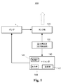
- FIG. 1 is a block diagram showing a schematic configuration of a pump control system according to a first embodiment of the present invention.
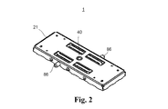
- FIG. 2 is an external perspective view of the pump of the pump control system according to the first embodiment of the present invention.
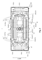
- FIG. 3 is a plan view showing a configuration of a main part of a pump of the pump control system according to the first embodiment of the present invention.
- FIG. 4 is an exploded perspective view of the pump of the pump control system according to the first embodiment of the present invention.
- FIG. 5 is a perspective view of a coil core portion of the pump of the pump control system according to the first embodiment of the present invention.
- FIG. 6 is a perspective view of a vibrating body in the pump of the pump control system according to the first embodiment of the present invention.
- FIG. 7 is a plan sectional view showing an internal configuration of a pump of the pump control system according to the first embodiment of the present invention.
- FIG. 8 is an exploded perspective view of a pump portion of the pump of the pump control system according to the first embodiment of the present invention.
- FIG. 9 is a diagram showing an air flow path of the pump portion of the pump of the pump control system according to the first embodiment of the present invention.
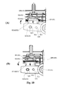
- 10A and 10B are diagrams showing an air discharge / suction operation in the pump of the control system pump according to the first embodiment of the present invention.
- FIG. 11 is a diagram showing a magnetic spring of the pump of the pump control system according to the first embodiment of the present invention.
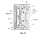
- FIG. 12 is a diagram showing a magnetic circuit configuration of a pump of the pump control system according to the first embodiment of the present invention.
- FIG. 13 is a diagram showing the operating principle of the pump.
- FIG. 14 is a diagram showing the frequency characteristics of the pressure of the air in the tank portion when the pump is open and when the pump is closed when the resonance type pump of the present embodiment is used.
- FIG. 15 is a diagram showing an example of frequency control in the pump control system according to the embodiment of the present invention.
- FIG. 16 is a diagram showing a frequency control flow of the pump control system according to the embodiment of the present invention.
- FIG. 17 is a block diagram showing a schematic configuration of a pump control system according to a second embodiment of the present invention.
- FIG. 18 is a diagram showing a pattern of drive frequency control when the tank capacities are different.
- FIG. 19 is a diagram showing a pattern of drive frequency control when the tank capacities are different.
- FIG. 20 is a diagram showing a table in the case where the drive frequency is switched by the pressure value using the pump control system of the first embodiment.
- 21A and 21B are diagrams showing a table in the case of switching the drive frequency with time using the pump control system of the second embodiment.
- FIG. 22 is a diagram showing a frequency control pattern according to the first embodiment and the second embodiment.
- FIG. 23 is a diagram showing a table in the case where the drive frequency is switched by the pressure value using the control system pump of the first embodiment.
- FIG. 24 is a diagram showing a table in the case of switching the drive frequency with time using the control system pump of the second embodiment.
- FIG. 25 is a diagram schematically showing a pump control system according to a third embodiment of the present invention.
- FIG. 1 is a block diagram showing a schematic configuration of a pump control system 100 according to an embodiment of the present invention.
- the pump control system 100 includes a pump 1, a tank unit 120, a pressure measuring unit (pressure detecting unit) 130, and a microcomputer unit (control unit) 140.
- the pump control system 100 is capable of outputting the fluid discharged from the pump 1, the air (gas) in the present embodiment, by adjusting the pressure in the tank unit 120.
- the frequency of the pump 1 is controlled by the drive signal (current supply) output from the microcomputer unit 140. Specifically, a drive signal having a resonance frequency is input to the vibration actuator constituting the pump 1 to electromagnetically drive the vibration actuator, and supply air as a fluid to the tank unit 120.
- a drive signal having a resonance frequency is input to the vibration actuator constituting the pump 1 to electromagnetically drive the vibration actuator, and supply air as a fluid to the tank unit 120.
- FIG. 2 is an external perspective view of the pump portion of the pump of the pump control system according to the first embodiment of the present invention.
- FIG. 3 is a plan view showing a configuration of a main part of a pump of the pump control system according to the first embodiment of the present invention.
- FIG. 4 is an exploded perspective view of the pump of the pump control system according to the first embodiment of the present invention.
- FIG. 5 is a perspective view of a coil core portion of the pump of the pump control system according to the first embodiment of the present invention.
- FIG. 6 is a perspective view of a vibrating body in the pump of the pump control system according to the first embodiment of the present invention.
- FIG. 7 is a plan sectional view showing an internal configuration of a pump of the pump control system according to the first embodiment of the present invention.
- FIG. 8 is an exploded perspective view of a pump portion of the pump of the pump control system according to the first embodiment of the present invention.
- the vibration direction of the vibrating body that reciprocates in the vibration actuator of the pump in the pump control system is the direction shown in FIG.
- the two directions orthogonal to this direction will be described as a lateral direction (horizontal direction) and a height direction (vertical direction, also referred to as a thickness direction), respectively.
- expressions indicating directions such as left / right (horizontal) and height (up / down) used to explain the configuration and operation of each part of the pump 1 are not absolute but relative. It is appropriate when each part of the pump is in the posture shown in the figure, but when the posture changes, it should be changed and interpreted according to the change in the posture.
- the pump 1 shown in FIGS. 2 and 3 discharges air by the action of an electromagnetically driven vibration actuator 10.
- the pump has been described as discharging and sucking air, but what is discharged and sucked by the pump is not limited to air, but may be a fluid, and a gas is particularly preferable.
- the height (length in the vertical direction in the drawing and corresponding to the thickness) of the pump 1 is horizontal (horizontal direction in the drawing) and vertical (depth direction in the drawing and vibration). It has a flat plate shape that is shorter than both directions. Also, the length is shorter than the width. Note that FIG. 2 is a perspective view of the pump 1 as viewed from the back surface side.
- the pump 1 includes a vibrating actuator 10 in which a vibrating body (movable body) 30 is reciprocally rotatably provided with respect to a fixed body 20 via a shaft portion 40, and a pump portion 80 that discharges and sucks air by driving the vibrating actuator 10. (80a, 80b) and.
- the vibrating body 30 is rotatably provided in the case 21 of the fixed body 20 via the shaft portion 40.
- the vibrating body 30 moves in the axial direction of the shaft portion 40 with respect to the fixed body 20. It reciprocates along, that is, it vibrates.
- the pump 1 can discharge and suck air from the discharge unit 86 by utilizing the vibration of the vibrating body 30.
- a vibrating body 30 is provided in a case 21 having a rectangular shape in a plan view so as to be reciprocally rotatable around a shaft portion 40 arranged at the center thereof.
- the magnets 70a and 70b are provided on the inner surfaces of both end wall portions that are separated from each other in the longitudinal direction of the vibrating body 30.
- the coil core portion 62a including the coil 50a and the core portion 60a is provided on the inner surface of the end wall portion of the case 21 on the side facing the magnet 70a, and the coil core portion 62b including the coil 50b and the core portion 60b faces the magnet 70b. It is provided on the inner surface of the end wall portion of the case 21 on the side of the coil.
- the magnets 70a and 70b are preferably permanent magnets, for example.
- the vibrating actuator 10 includes a fixed body 20, a shaft portion 40, and a vibrating body 30 that is rotatably supported with respect to the fixed body 20 via the shaft portion 40.
- the vibrating actuator 10 is provided with magnets 70 (70a, 70b) on one of the fixed body 20 and the vibrating body 30, and the magnetized surface of the core faces the magnet 70 on the other side of the fixed body 20 and the vibrating body 30.
- Coil core portions 62 (62a, 62b) arranged so as to be provided are provided.
- the vibrating body 30 is provided with magnets 70 (70a, 70b), and the fixed body 20 is provided with coil core portions 62 (62a, 62b).
- the vibrating body 30 includes magnets 70 (70a, 70b), and the fixed body 20 includes coil core portions 62 (62a, 62b).
- the vibrating actuator 10 electromagnetically drives the vibrating body 30 by supplying an electric current to the coils 50a and 50b, and vibrates the vibrating body 30 which is a vibrating body.
- the fixed body 20 has a case 21, a cover 22, and coil core portions 62a and 62b. Further, the fixed body 20 is provided with pump portions 80 (80a, 80b).
- the case 21 functions as a housing for the pump 1 and has a rectangular box shape that opens on one side.
- a shaft portion 40 is erected in the case 21, and rotatably supports the vibrating body 30 arranged in the case 21.
- the coil core portions 62a and 62b are arranged on the inner surfaces of the both end wall portions separated in the longitudinal direction of the case 21 so as to face the magnets 70a and 70b of the vibrating body 30, respectively.
- the opening portion of the case 21, in the present embodiment, the opening portion that opens upward is covered with the cover 22.
- the case 21 and the cover 22 function as a hollow electromagnetic shield, and the pump 1 has a flat plate shape.
- the shaft portion 40 is provided on the bottom surface of the case 21 at the center of the case 21 in the lateral direction and the depth direction so as to extend in the height direction of the case 21.
- the shaft portion 40 is fitted and fixed to the shaft hole 23 of the cover 22 by press fitting or adhesion after insertion in a state of being inserted into the bearing portion 34 of the vibrating body 30.
- the shaft portion 40 is supported in a state of being inserted into the bearing portion 34 of the vibrating body 30 and erected on the bottom surface of the case 21 and the cover 22.
- the coil core portions 62a and 62b are arranged to face each other on the inner surfaces of both end wall portions separated in the longitudinal direction in the case 21. Further, the coil core portions 62a and 62b are arranged so as to sandwich the vibrating body 30 in the longitudinal direction of the case 21.
- the coil core portions 62a and 62b are similarly configured in this embodiment, and are provided at positions symmetrical with respect to the axis of the shaft portion 40 in a plan view.
- the core portions 60a and 60b are magnetic materials that are magnetized by energizing the coils 50a and 50b.
- the core portions 60a and 60b may be made of, for example, electromagnetic stainless steel, a sintered material, a MIM (metal injection mold) material, a laminated steel plate, an electrogalvanized steel plate (SECC), or the like.
- the core portions 60a and 60b are composed of laminated cores made of laminated steel plates.
- the core portions 60a and 60b are magnetic poles (hereinafter, for convenience, referred to as "core magnetic poles") 602a formed continuously at both ends of the cores 601a and 601b around which the coils 50a and 50b are wound and both ends of the cores 601a and 601b. , 603a, 602b, 603b.
- each of the core magnetic poles 602a, 603a, 602b, and 603b has a curved magnetic pole surface having an arc shape in a plan view according to the magnetized surface shape of the reciprocating rotating magnets 70a and 70b.
- the core magnetic poles 602a and 603a of the core portion 60a face the magnet 70a, and the core magnetic poles 602b and 603b of the core portion 60b face the magnet 70b.
- the core magnetic poles 602a, 603a, 602b, and 603b are arranged side by side in the rotation direction of the reciprocating rotation of the vibrating body 30.
- the core magnetic poles 602a, 603a, 602b, and 603b are preferably arranged on the circumference of a circle centered on the shaft portion 40. This circumference is a circumference along the motion trajectory of the magnets 70a and 70b.
- the core magnetic poles 602a, 603a, 602b and 603b of the core portions 60a and 60b around which the coils 50a and 50b are wound are arranged so as to face the magnetizing direction of the magnets 70a and 70b.
- the coils 50a and 50b are connected to, for example, a power supply unit (not shown) in each of the core units 60a and 60b.
- the coils 50a and 50b excite the core magnetic poles 602a, 603a, 602b and 603b by supplying power from the power supply unit.
- the core magnetic poles 602a and 602b and the core magnetic poles 603a and 603b are excited with different polarities.
- the vibrating body 30 has a direction (longitudinal direction of the case 21) orthogonal to the shaft portion 40 (rotating axis of the vibrating body 30) in the case 21 of the fixed body 20. ) Extends and is placed.
- the vibrating body 30 is rotatably supported in the case 21 around the shaft portion 40.
- the vibrating body 30 presses the vibrating body body 32, the bearing portion 34, and a pair of magnets 70a and 70b in which a plurality of magnetic poles (three poles in this embodiment) are alternately arranged in the rotation direction (depth direction). It has a part 35 and.
- a bearing portion 34 is fixed to the vibrating body main body 32, and a shaft portion 40 is inserted through the bearing portion 34.
- a pair of magnets 70a and 70b are fixed to the vibrating body main body 32 so as to sandwich the shaft portion 40 inserted via the bearing portion 34.
- the vibrating body 32 may or may not be a magnetic body (ferromagnetic material), is a yoke in the present embodiment, and functions as a weight of the vibrating body 30.
- the vibrating body body 32 is configured by, for example, laminating yoke iron cores.
- the constituent material of the vibrating body 32 is not limited to the metal material, and a resin material or the like may be used.
- the vibrating body 32 has a central opening 322 to which the bearing portion 34 is fixed in the central portion, and arm portions 324a and 324b extending in opposite directions from the central portion.
- the arm portions 324a and 324b have an elongated flat plate shape, and their respective tip portions are formed so as to project in a direction intersecting the extending direction. Further, magnet fixing portions 326a and 326b are formed on the tip surfaces of the arm portions 324a and 324b.
- the tip surfaces of the magnet fixing portions 326a and 326b are formed by being curved in an arc shape, and the magnets 70a and 70b are fixed to the tip surfaces. Further, the arm portions 324a and 324b are provided with a pressing portion 35.
- Magnetics 70a, 70b The magnets 70a and 70b, together with the coil core portions 62a and 62b arranged to face each other, form a magnetic circuit for driving the vibration actuator 10.
- the magnets 70a and 70b have magnetic pole surfaces 72 that function as a plurality of magnetic poles, and the magnetic pole surfaces 72 of the magnet 70a and the magnetic pole surfaces 72 of the magnet 70b are arranged so as to face opposite to each other with the shaft portion 40 interposed therebetween.
- the magnets 70a and 70b are separated from each other in the extending direction of the vibrating body body 32 into which the shaft portion 40 is inserted at the central portion, that is, at the tip portions of both arm portions 324a and 324b, respectively.
- the magnetic pole surface 72 is provided so as to face outward.
- the magnetic pole surface 72 includes three different magnetic poles 721, 722, and 723 that are alternately arranged, as shown in FIGS. 3-7 and 11.
- the magnets 70a and 70b may be configured by alternately arranging a plurality of magnets (magnet pieces) having different magnetic poles, or may be magnetized so as to be arranged in the rotation direction and have different magnetisms alternately.
- the magnets 70a and 70b are composed of, for example, an Nd sintered magnet or the like.
- the magnetic poles 721, 722, and 723 of the magnets 70a and 70b are arranged adjacent to each other in the depth direction, that is, in the rotation direction, which sandwiches the shaft portion 40 and is orthogonal to the axis of the shaft portion 40.
- the magnets 70a and 70b are arranged at both ends of the vibrating body 30 so that the magnetic pole surfaces 72 are located on the circumference of a circle centered on the shaft portion 40.
- the magnets 70a and 70b are in a normal state, that is, in a non-energized state in which no current is supplied to the coils 50a and 50b, the central position of the length of the central magnetic pole 722 of the respective magnetic pole surfaces 72 in the rotational direction is , Is provided so as to be located at the center position between the core magnetic poles 602a and 603a.
- the magnets 70a and 70b are placed on the inner surfaces of both end walls of the housing (case 21) at positions most distant from each other in the vibrating body 30 via the shaft portions 40 and the arm portions 324a and 324b. It is arranged so as to face each of the coil core portions 62a and 62b provided respectively.
- the pressing portion 35 presses the movable wall 822 of the pair of closed chambers 82 of the pump portion 80 when the vibrating body 30 rotates and moves.
- the pressing portion 35 has a pair of pressing elements 351 that press the movable walls 822 of the pair of closed chambers 82 when the arm portions 324a and 324b reciprocate.
- the pair of pressers 351 of the pressing portion 35 are provided on the arm portions 324a and 324b so as to project in the width direction, that is, in the rotation direction.
- the pressing portion 35 may be formed so as to linearly press the movable wall 822 in the opposite direction even when the vibrating body 30 rotates, for example.
- each presser 351 of the pressing portion 35 moves in an arc shape around the shaft portion 40, abuts on the movable wall 822, and presses the movable wall 822.
- the pressing portion 35 may be configured in any configuration as long as it is displaced toward the movable wall side and presses the movable wall 822 to move the movable wall 822 with the rotational movement of the vibrating body 30. It is desirable that the movable wall 822 is arranged so as to intersect the moving path of the pressing portion 35, and the moving pressing portion 35 is arranged so as to be in surface contact with the movable wall 822.
- the pressing portion 35 has arm portions 324a and 324b via a shaft protrusion 353 rotatably attached to the round hole 328 and a guide protrusion 352 guided to the elongated hole 329. It is fixed for each of.
- the presser 351 swings in an arc shape as the vibrating body 30 reciprocates.
- the guide protrusion 352 is loosely fitted in the elongated hole 329, and the pressing portion 35 can swing with respect to the arm portions 324a and 324b by the guide protrusion 352, so that the tip of the presser 351 can swing. You may.
- the pressing portion 35 moves in an arc shape, but the pressing element 351 can be linearly moved with respect to the movable wall 822 to be pressed.
- the pressing portion 35 is connected to the movable wall 822 of the pump portion 80 via the pressing element 351.
- the presser 351 is inserted into the insertion portion 822a of the movable wall 822, which is a diaphragm, and presses and displaces the movable wall 822 in the rotational direction.
- the pressing portion 35 presses the movable wall 822 when it moves to the movable wall 822 side due to the rotation of the vibrating body 30.
- the bearing portion 34 is formed of, for example, a sintered sleeve bearing.
- the bearing portion 34 is fitted to the central opening 322 of the vibrating body main body 32 so that the shaft portion 40 is located on the central axis of the vibrating body main body 32.
- the vibrating body 32 When the coil 50a and 50b are not fed, the vibrating body 32 is positioned at the center in the longitudinal direction in the case 21 (fixed body 20) by the function of the magnetic spring by the core portions 60a and 60 and the magnets 70a and 70b. Be urged to do.
- Each of the pump portions 80 (80a, 80b) has a movable wall 822, a closed chamber 82 defined by the movable wall 822, a suction portion 83, a valve 84, a discharge portion 86, and a discharge flow path portion 88.
- the movable wall 822 constitutes a wall portion that separates the chamber forming portion 824 and the discharge flow path portion 88, and is provided so as to be displaceable.
- the movable wall 822 changes the volume in the closed chamber 82 by being displaced by the vibration of the vibrating body 30.
- the movable wall 822 and the chamber forming portion 824 form a closed chamber 82.
- the movable wall 822 is formed of, for example, an elastically deformable material, and is provided so as to close the chamber forming portion 824.
- the movable wall 822 is, for example, a diaphragm.
- the movable wall 822 has an insertion portion 822a into which the pressing element 351 of the pressing portion 35 is inserted, and is connected to the pressing portion 35 via the insertion portion 822a.
- the movable wall 822 is pressed and displaced by the pressing portion 35 that moves with the rotation of the vibrating body 30.
- the movable wall 822 is elastically deformed by being pressed toward the chamber forming portion 824 by the pressing portion 35 via the insertion portion 822a, and is deformed so that the volume of the chamber forming portion 824 is reduced.
- the volume of the closed chamber 82 can be changed by displacing the movable wall 822 toward the chamber forming portion 824 and projecting into the chamber forming portion 824.
- the movable wall 822 is inserted into the chamber forming portion 824 by the forward rotation movement of the reciprocating rotation of the vibrating body 30 (swinging to one side in the rotation direction), presses the inside of the chamber forming portion 824, and is inside the closed chamber 82. Reduce capacity and expel air. On the other hand, when the vibrating body 30 revolves (moves to the other side in the rotation direction), the movable wall 822 increases the capacity in the closed chamber 82 and allows air to flow in.
- the closed chamber 82 is a closed space in which the suction unit 83 and the discharge unit 86 are connected and the volume is changed by the displacement of the movable wall 822.
- the discharge unit 86 has a discharge port that communicates with the outside, and discharges air from the pump 1 to the outside through the discharge port.
- the discharge port is an opening that communicates with the discharge portion 86 connected to the bottom surface of the closed chamber 82.
- the movable wall 822 when the movable wall 822 is pressed by the pressing unit 35, the movable wall 822 elastically deforms toward the inside of the closed chamber 82 and presses the air in the closed chamber 82.
- the pressed air in the closed chamber 82 is discharged to the outside via the discharge unit 86.
- the suction portion 83 is moved into the closed chamber 82. Air is sucked in from the outside through.
- the suction unit 83 has a suction port and sucks air into the closed chamber 82 through the suction port.
- the suction port is an opening communicating with the suction section 83 in the chamber forming section 824.
- the pump portions 80 (80a, 80b) are respectively arranged in the case 21 along the extending direction of the vibrating body 30, that is, the side wall portion extending in the longitudinal direction of the case 21. Further, the pump portions 80 (80a, 80b) are arranged so as to sandwich the vibrating body body 32 of the vibrating body 30 in the depth direction of the case 21.
- the pump section 80 includes, for example, a base 801, a diaphragm section 802, a cylinder section 803, a valve section 804, a valve cover section 805, a partition section 806, and a flow path forming section 807.
- the base 801 and the diaphragm portion 802, the cylinder portion 803, the valve portion 804, the valve cover portion 805, the partition portion 806, and the flow path forming portion 807 each have an elongated plate shape extending in the longitudinal direction of the case 21.
- a pump portion 80 having a sealed internal space is formed by being laminated.
- the base 801 has an opening, and the insertion portion 822a of the diaphragm portion 802 is inserted from the back side into the opening, and the insertion portion 822a is arranged in a state of projecting to the front side.
- the base 801 and the flow path forming portion 807 form a housing of the strip-shaped pump portion 80.
- the diaphragm portion 802 is formed of an elastic material such as rubber.
- the diaphragm portion 802 has an insertion portion 822a and a movable wall 822.
- a chamber forming portion 824 of the cylinder portion 803 is arranged on the back surface side of the movable wall 822 that is flexible and elastically deformed.
- the diaphragm portion 802 and the cylinder portion 803 are attached to each other so that the movable wall 822 of the diaphragm portion 802 and the chamber forming portion 824 of the cylinder portion 803 form a closed chamber 82 which is a closed space.
- the cylinder portion 803 has a chamber forming portion 824, and in the closed chamber 82, two communication holes communicating with the discharge portion 86 and the suction portion 83 are formed on the surface facing the movable wall 822.
- the two communication holes are formed from the back side of the cylinder portion 803 via the valve 84 of the valve portion 804 attached so as to overlap the communication holes, respectively, and the discharge flow path portions of the valve cover portion 805 and the flow path forming portion 807, respectively. It is connected to 88 and the suction unit 83.
- the valve portion 804 is attached to the valve cover portion 805.
- the valve 84 connected to the discharge portion 86 is configured to communicate with the discharge portion 86 of the flow path forming portion 807 when the capacity in the closed chamber 82 decreases.
- the valve 84 connected to the discharge portion 86 is configured to close when the capacity in the closed chamber 82 increases.
- the valve 84 connected to the suction unit 83 is configured to close when the capacity in the closed chamber 82 decreases.
- the valve 84 connected to the suction unit 83 is configured to communicate with the suction unit 83 of the flow path forming unit 807 when the capacity of the closed chamber 82 increases.
- each of the pump portions 80 has a pair of closed chambers 82 including a movable wall 822 and a chamber forming portion 824.
- Each of the pump portions 80 (80a, 80b) is arranged such that its pair of closed chambers 82 face each side surface of the arm portions 324a and 324b extending in opposite directions with the shaft portion 40 in between. There is. That is, the pump portion 80 (80a, 80b) is at a position where the pair of closed chambers 82 of the pump portion 80 (80a, 80b) sandwich the arm portions 324a and 324b in the direction in which the arm portions 324a and 324b reciprocate and rotate. And they are arranged so as to face each other.
- FIGS. 10A and 10B are diagrams showing an air discharge / suction operation in the pump of the pump control system according to the first embodiment of the present invention.
- the magnets 70a and 70b arranged at both ends of the vibrating body 30 facing each other with the vibrating body shaft portion 40 sandwiching the vibrating body shaft portion 40 in the case 21 are longitudinally provided with each of the magnets 70a and 70b.
- the core portions 60a and 60b, which are magnetic materials, are arranged so as to face each other so as to be separated from each other in the direction.
- the core portions 60a and 60b are respectively arranged on the inner surfaces of both end wall portions in the longitudinal direction of the case 21 so as to be separated from each other in the longitudinal direction and face each other.
- Magnetic attraction is generated between the core portion 60a and the magnet 70a, and between the core portion 60b and the magnet 70b, respectively.
- the two magnetic attraction forces generated in the longitudinal direction are generated on the same straight line and in opposite directions with the shaft portion 40 in between, so that they cancel each other out.
- FIG. 11 is a diagram showing a magnetic spring of the pump of the pump control system according to the first embodiment of the present invention.
- the magnetic circuit provided by the coil core portion 62a and the magnet 70a and the magnetic circuit provided by the coil core portion 62b and the magnet 70b are point-symmetrically configured around the shaft portion 40. Therefore, in FIG. 11, only the magnetic circuit provided by the coil core portion 62a and the magnet 70a will be described, and the description of the magnetic circuit provided by the coil core portion 62b and the magnet 70b will be omitted.
- the magnet 70a has a configuration in which the magnetic poles 721, 722, and 723 are N poles, S poles, and N poles, respectively, on the magnetic pole surface 72 facing the core portion 60a.
- the magnetic poles 721 to 723 on the magnetic pole surface 72 of the magnet 70a attract the core magnetic poles 602a and 603a, which are close to each other, respectively.
- the central magnetic pole 722 of the magnet 70a attracts both the core magnetic poles 602a and 603a.
- the magnetic pole 721 of the magnet 70a attracts the core magnetic pole 602a, and the magnetic pole 723 of the magnet 70a attracts the core magnetic pole 603a.
- the magnetic pole 722 at the center of the magnet 70a is located between the central portion of the coil core portion 62a, that is, the core magnetic poles 602a and 603a.
- the vibrating body 30 including the magnets 70a and 70b rotates and reciprocates (rotationally reciprocating vibration) in the rotational direction around the shaft portion 40. ..
- FIG. 12 is a diagram showing a magnetic circuit configuration of a pump of the pump control system 100 according to the first embodiment of the present invention.
- the magnetic circuit provided by the coil core portion 62a and the magnet 70a will be described as in the description with reference to FIG. 11, and the coil core portion 62b and the magnet 70b will be described.
- the description of the magnetic circuit provided by the above will be omitted.
- the magnet 70a has three polar poles arranged alternately in the rotation direction of the vibrating body 30 on the magnetic pole surface 72.
- the central magnetic pole 722 is the S pole
- the magnetic poles 721 and 723 sandwiching the central magnetic pole 722 are the N poles, respectively.
- the magnetic pole 723 of the magnet 70a facing the core magnetic pole 603a which is the north pole is the north pole, it repels the core magnetic pole 603a which is the north pole.
- the magnetic pole 722 of the magnet 70a is the S pole, a magnetic attraction force is generated between the magnetic pole 722 and the core magnetic pole 603a which is the N pole, but repels the core magnetic pole 602a which is the S pole.
- the magnetic pole 721 of the magnet 70a is the N pole, a magnetic attraction force is generated between the magnetic pole 721 and the core magnetic pole 602a which is the S pole.
- a current is supplied to the coil 50a in the opposite direction to reverse the polarity of the core portion 60a, that is, the magnetic pole 603a of the core portion 60a facing the magnet 70a is set to the S pole and the magnetic pole 602a is set to the N pole.
- the magnet 70a facing the core portion 60a rotates and moves in the direction opposite to the F1 direction ( ⁇ F1 direction).
- the vibrating body 30 is driven in the ⁇ F1 direction, which is the opposite of the F1 direction.
- the relationship between the magnet 70b arranged on the opposite side of the magnet 70a across the shaft portion 40 and the coil core portion 62b is centered on the shaft portion 40 with respect to the relationship between the magnet 70a and the coil core portion 62a. It becomes point symmetric. Therefore, between the magnet 70b and the coil core portion 62b, a thrust in the F1 direction or the ⁇ F1 direction is similarly generated between the magnet 70a and the coil core portion 62a.
- the vibrating body 30 preferably rotates and reciprocates around the shaft portion 40 due to the magnetic attraction force and the repulsive force effectively generated in the magnetic circuit at both ends of the vibrating body 30.
- Pump 1 includes a coil 50a, and supplies the alternating current of a frequency substantially equal to the resonance frequency f r of the vibrator 30 to 50b, the coil 50a, the core section 60a through 50b, 60b (core in particular magnetic pole 602a, 603a , 602b, 603b) are excited. As a result, the vibrating body 30 can be driven efficiently.
- the vibrating body 30 in the vibrating actuator 10 is supported by a spring mass system structure composed of coil core portions 62a and 62b having coils 50a and 50b and core portions 60a and 60b, respectively, and magnetic springs provided by magnets 70a and 60b. It is in a state.
- the coil 50a, the 50b alternating current having a frequency equal to the resonant frequency f r of the vibrator 30 is supplied to the vibrating body 30 is driven at resonance.
- the equation of motion and the circuit equation showing the driving principle of the vibration actuator 10 are shown below.
- the vibration actuator 10 is driven based on the equation of motion represented by the following equation (2) and the circuit equation represented by the following equation (3).
- the vibration actuator 10 of the pump 1 when the coil 50a, the power supply to 50b was carried out by alternating current corresponding to the resonance frequency f r which is determined by the spring constant K sp moment of inertia J and the magnetic spring of the vibrating body 30
- a large vibration output can be efficiently obtained.
- the pump 1 when the vibrating body 30 reciprocates, the volume inside the closed chamber 82 changes due to the displacement of the movable wall 822 of the pump unit 80 (specifically, the deformation of the diaphragm), and the pump functions as a pump.
- the function of this pump is such that the flow rate is set by the following formula (4) and the pressure is set by the following formula (5).
- the flow rate Q [L / min], the piston area A [m 2 ], the piston displacement x [m], the drive frequency f [Hz], and the like in the pump 1 can be appropriately changed within the range satisfying the equation (4).
- the increasing pressure [kPa], atmospheric pressure P 0 [kPa], closed chamber volume V [m 3 ], fluctuating volume ⁇ V [m 3 ] piston area [m 2 ]
- a * piston displacement [m] is expressed by the equation ( It can be changed as appropriate within the range that satisfies 5).
- the pump 1 of the present embodiment has a vibration actuator 10 that is electromagnetically driven, and pump units 80 (80a, 80b) that suck and discharge air by the electromagnetic drive of the vibration actuator 10.
- the fixed body 20 includes one of a coil core portion 62a having a coil 50a and a core 60a around which the coil 50a is wound, and a magnet 70a arranged to face the end portion of the core 60a.
- the fixed body 20 is provided with a pump portion 80.
- the vibrating body 30 includes the other of the coil core portion 62a and the magnet 70a, and is elastically held by the magnetic attraction force of the magnet 70a.
- the shaft portion 40 supports the vibrating body 30 so as to be reciprocally rotatable.
- the pump unit 80 has a movable wall 822 that is movable by the rotational movement of the vibrating body 30, a closed chamber 82 that communicates with the air discharge port 86 and the air suction port 83, and whose volume is changed by the displacement of the movable wall 822.
- the vibrating body 30 has a pressing portion 35 that moves in an arc shape around the shaft portion 40 with the reciprocating rotational movement of the vibrating body 30 and abuts and presses against the movable wall 822.
- the movable wall 822 is arranged in the moving direction of the pressing portion 35, is displaced when pressed by the pressing portion 35, and discharges the air in the closed chamber 82 through the discharge port 86.
- the tank unit 120 adjusts the pressure of the fluid discharged from the pump unit 1. Specifically, the tank unit 120 collects the air discharged from the closed chamber 82 of the pump 1 and increases the pressure of the air discharged from the tank unit 120. The tank unit 120 is connected to the tank discharge path, and by accommodating the air discharged from the closed chamber 82 without outputting it to the outside, the air is stored in the tank unit 120 and the pressure in the tank unit 120 is released. It is adjustable. The tank portion 120 is connected to the discharge port 86 of the pump 1 and communicates with the closed chamber 82 of the pump 1 (pump portion 80).
- the tank unit 120 may store the supplied fluid, increase the pressure of the fluid in the tank unit 120, and appropriately release the fluid at a desired pressure.
- the tank portion 120 may be any device as long as it has a capacity capable of accumulating air and increasing the pressure of the fluid discharged from the tank portion 120 and uses the supplied air. For example, blood pressure. It may be used as a total cuff or the like.
- the pressure measuring unit 130 measures the state of air (fluid) in the tank unit 120. Specifically, the pressure measuring unit 130 measures the pressure of the air (fluid) in the tank unit 120, obtains pressure value information indicating the pressure value, and outputs the pressure information to the microcomputer unit 140.
- the pressure measuring unit 130 may be configured in any way as long as the pressure of the air (fluid) in the tank unit 120 can be measured.
- the pressure measuring unit 130 may be provided in the tank unit 120, or may be provided in the tank unit 120.
- the microcomputer unit 140 includes an acquisition unit 146, an output unit 144, and a storage unit 142.
- the acquisition unit 146 acquires the value of the air pressure in the tank unit 120 based on the pressure information input from the pressure information measurement unit 130.
- the acquisition unit 146 is connected to the pressure measurement unit 130 and acquires the measured pressure value of the air in the tank unit 120 based on the pressure information input from the pressure measurement unit 130.
- the output unit 144 has a function of outputting a drive frequency to the coils 50a and 50b.
- the output unit 144 outputs the drive frequency based on the information of the pressure value of the air in the tank unit 120 acquired by the acquisition unit 146 to the coils 50a and 50b of the pump 1.
- the microcomputer unit 140 has a function as a control unit, and changes the vibration of the vibration actuator of the pump 1 based on the measured pressure value of the air in the tank unit 120.
- the microcomputer unit 140 acquires the pressure value of the air in the tank unit 120, here, the measured pressure value as the pressure value information, and based on the acquired pressure value information, moves to the coils 50a and 50b. Controls the drive frequency of the supplied current.
- the microcomputer unit 140 changes the frequency of the drive signal output to the pump 1 to change the pressure of the air in the tank unit 120.
- the microcomputer unit 140 controls the drive frequency so that a current having a resonance frequency of a vibrating body 30 that differs depending on the pressure of air in the tank unit 120 is supplied to the coils 50a and 50b.
- the microcomputer unit 140 refers to, for example, a look-up table stored in the built-in ROM used as the storage unit 142 so that the pressure of the air in the tank unit 120 becomes a desired pressure. Control to store air inside.
- a look-up table a table or the like for associating the drive frequency with the pressure value of the air in the tank unit 120 and switching the drive frequency according to the pressure value of the air in the tank unit 120 can be used.
- the microcomputer unit 140 maximizes the first drive frequency that maximizes the flow rate of air from the pump 1 to the tank unit 120 (see G2 in FIG. 14) and the pressure of the air in the tank unit 120 (see G1 in FIG. 14).
- the drive frequency supplied to the coils 50a and 50b is switched between the second drive frequency to be changed.
- the microcomputer unit 140 switches the drive frequency from the first drive frequency (see H1 in FIG. 14) to the second drive frequency (see H2 in FIG. 14) in the process of increasing the pressure of the air in the tank unit 120. ..
- the pressure value at the timing of switching the drive frequency in the process of increasing the pressure of the air in the tank portion 120 is also referred to as a process value for convenience.
- the pressure of the air in the tank portion 120 can be increased more efficiently and in a shorter time than in the case of controlling with the first drive frequency (see H1 in FIG. 14).
- the microcomputer unit 140 controls each unit by a program stored in a ROM or the like. Thereby, for example, the drive signal of the drive frequency changed based on the acquired pressure value information of the air in the tank portion 120 can be supplied to the coils 50a and 50b to control the pump 1.
- the pump control system 100 of the present embodiment has a frequency of a drive signal for driving the vibrating body 30 based on the pressure in the tank portion 120 when driving the vibrating body 30 of the resonance type vibrating actuator 10 of the pump 1.
- the drive signal having a frequency corresponding to the pressure of the air in the tank portion 120 is supplied to the coils 50a and 50b of the pump 1.
- the pump 1 needs to secure the required flow rate of the fluid to be conveyed (air) and the magnitude of the pressure on the fluid to be conveyed (air pressure).
- FIG. 13 is a diagram showing the operating principle of the pump 1 of the pump control system 100.
- FIG. 13A is a conceptual diagram showing a state in which the discharge path of the pump is open in the pump 1, such that the tank portion is not connected to the discharge port (corresponding to the discharge portion 86).
- FIG. 13B is a conceptual diagram showing a state in which the discharge path of the pump is closed by attaching the tank to the discharge port of the pump.
- FIG. 13A when the discharge path of the resonance-driven pump is open (also referred to as “when the pump is open”), when the pump vibrates, that is, when the movable wall is displaced by the drive of the pump portion, the moving wall is displaced from the closed chamber. The discharged air is discharged to the outside of the pump through the discharge port.
- FIG. 13B when the tank portion (corresponding to the tank portion 120) is connected to the pump to be driven by resonance and the discharge path to the outside of the pump is blocked (also referred to as “when the pump is closed”). The air in the tank acts on the vibration of the pump. This is because the closed chamber and the tank portion communicate with each other through a discharge port (corresponding to the discharge portion 86).
- the air in the tank portion that communicates with the closed chamber and the fluid acts on the pump 1 (more specifically, the pump portion 80 and the vibrating body 30) via the supplied air, and acts as an air spring in the pump 1.
- the resonance frequency f when the pump is open which is represented by the following equation (6)
- the resonance frequency f'when the pump is closed which is represented by the following (7). That is, when the pressure in the tank portion 120 is increased by driving the pump 1 when the pump is closed, the springiness is also increased, and the resonance frequency of the pump actuator is higher than when the pump is opened.
- FIG. 14 is a diagram showing the frequency characteristics of the pressure of the air in the tank portion when the pump is open and when the pump is closed when the resonance type pump of the present embodiment is used.
- the air pressure G1 in the tank portion at each drive frequency and the air flow rate from the pump to the tank portion at the time of opening the circuit are shown.
- the maximum value of each pressure G2 (hereinafter, G2 represents the flow rate of air from the pump to the inside of the tank is referred to as the flow rate G2) is realized by driving in different resonance frequency bands (near resonance points H1 and H2).
- the flow rate G2 increases if the pump is driven at the drive frequency H1 (first drive frequency H1) at the time of opening the circuit (FIG. Then the maximum value).
- the circuit is closed, air acts on the vibrating body 30 as a spring, so that the resonance point of the vibrating body 30 of the pump shifts (the resonance point shifts to H2 in FIG. 14), and the pressure G1 is difficult to increase.
- the microcomputer unit 140 when the microcomputer unit 140 (control unit) increases the pressure in the tank unit 120 having a predetermined capacity to a predetermined pressure value, the drive frequency To change.
- the microcomputer unit 140 has a first drive frequency H1 that maximizes the air flow rate G2 from the pump 1 to the tank unit 120, and a second drive frequency that maximizes the air pressure G1 in the tank unit 120.
- the drive frequency is changed by switching the drive frequency between H2 and H2.
- FIG. 15 is a diagram showing an example of frequency control in the pump control system 100 according to the embodiment of the present invention.
- the microcomputer unit 140 supplies air (fluid) into the tank unit 120, and the pressure of the air in the tank unit 120 until the pressure of the air in the tank unit 120 reaches a desired pressure. To increase.
- the desired pressure (value) appropriately differs depending on the application target of the pump control device and the pump control system 100 of the present embodiment.
- the hypertension treatment guideline JSH2004
- the hypertension is 18 kPa (135 mmHg) or more, and the non-invasive mechanical blood pressure.
- T115 the JIS standard
- the desired pressure value may be set to 40 kPa and may be changed from 18 kPa to 40 kPa.
- the microcomputer unit 140 supplies the coil coils 50a and 50b with a drive signal having a frequency in which the pressure increases rapidly from 0, that is, a frequency in which the pressure rises from 0 and has a high degree of increase. More specifically, the lower frequency of the first drive frequency H1 and the second drive frequency H2 (shown by H1 as in FIG. 14), that is, the drive signal of the first drive frequency H1 is transmitted to the coils 50a and 50b. Input and excite.
- FIG. 15 shows the relationship between the drive at the first drive frequency H1 and the pressure due to the drive at the second drive frequency H2 (> H1) (shown by H2 as well as the frequency shown by H2 in FIG. 14) and the pressure increase time. Is shown. Then, the microcomputer unit 140 switches from the processing of the first driving frequency H1 to the processing of the second driving frequency H2 at a predetermined switching timing. This switching timing is changed based on the pressure state of the air in the tank portion 120. In FIG. 15, the timing at which the inclination indicating the increase in the pressure value of the air in the tank portion 120 becomes gentle is indicated by “frequency switching”. At this gradual timing, the drive frequency is changed from the first drive frequency H1 to the second drive frequency H2.
- the pump 1 is driven by the drive signal of the first drive frequency H1 in which the pressure of the air in the tank portion 120 increases quickly, and the drive signal of the first drive frequency H1 is driven. Then, the drive frequency is changed from the first drive frequency H1 to the second drive frequency H2 at the timing when the inclination indicating the increase in the pressure of the air in the tank portion 120 becomes gentle (“frequency switching” in FIG. 15). .. In this way, the characteristic of shifting from the first drive frequency H1 to the second drive frequency H2 to the drive frequency is shown by K1 in FIG.
- the first drive frequency H1 and the second drive frequency H2 are compared, and the pressure value at the timing of rising from 0 and switching the drive frequency, that is, up to the process value (about 10 kPa).
- the coils 50a and 50b are excited to resonately drive the vibrating body 30 at the first driving frequency in which the pressure increase time is short.
- the increase time of the air pressure in the tank portion 120 is short up to about 10 kPa.
- the pressure in the tank portion 120 does not increase to a desired pressure value (for example, 40 kPa).
- the pressure of the air in the tank portion 120 can be exceeded by a desired high pressure (for example, 40 kPa), but the first The pressure increase time from 0 to the process value (about 10 kPa) of the air in the tank portion 120 is longer than that in the case of resonance driving by the drive frequency H1. Therefore, in the present embodiment, the resonance drive of the pump 1 is started by the drive signal of the first drive frequency H1, and the drive frequency of the drive signal is changed to the second drive frequency H2 at a predetermined switching timing, for example, 10 KPa. .. As a result, the pump 1 can be driven by the characteristic K1 shown in FIG.
- the characteristic curve of the characteristic K1 is more than the characteristic curve in the case of resonance driving only at the second drive frequency H2 (the graph shown by the dotted line in FIG. 15).
- the desired high pressure eg 40 kPa
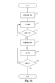
- FIG. 16 is a diagram showing an example of a control flow of the pump according to the embodiment of the present invention.
- the drive frequency of the drive signal of the pump control system 100 is set to the drive frequency 1 (first drive frequency H1).
- the microcomputer unit 140 measures the pressure in the tank unit 120 by the pressure measuring unit 130, and acquires it as the pressure value of the air in the tank unit 120 by the acquisition unit 146.
- the microcomputer unit 140 determines whether or not the acquired air pressure value is a switching pressure value (process value), and repeats the determination until the acquired air pressure value reaches the switching pressure value. ..
- step S13 the first drive frequency H1 for maximizing the flow rate G2 of air (fluid) from the pump 1 to the tank portion 120 and the second driving frequency H1 for maximizing the pressure G1 of the air (fluid) in the tank portion 120 are maximized.
- the drive frequency of the current supplied to the coils 50a and 50b is switched between the drive frequency H2 and the drive frequency H2. If the pressure value reaches the switching pressure value in step S13, the process proceeds to step S14, and the drive frequency of the current supplied to the coils 50a and 50b is set to the drive frequency 2 (second drive frequency H2). do.
- the microcomputer unit 140 measures the pressure of the air in the tank unit 120 (step S15), and determines whether or not the pressure is required, that is, whether or not the desired pressure value has been reached (step S16). , Repeat this until the desired pressure value is reached.
- the pump can be miniaturized, more suitable pump pressure and flow rate can be secured, and stable driving can be performed.
- the pressure of air in the tank portion 120 can be increased in a shorter time than driving at a single frequency.
- FIG. 17 is a block diagram showing a schematic configuration of a pump according to a second embodiment of the present invention.
- the pump control system 100A shown in FIG. 17 uses a timer 160 instead of the pressure detection unit 130 (see FIG. 1) as compared with the pump control system 100.
- the basic configuration of the pump control system 100A according to the second embodiment is the same as the basic configuration of the pump control system 100 of the first embodiment, only different configurations will be described, and the same configuration will be the same. The same name is given and the description is omitted.
- the pump control system 100A includes a pump 1, a tank unit 120, a microcomputer unit 140A, and a timer 160.
- the timer 160 measures the driving time of the vibrating body 30 when increasing the pressure of the air (fluid) in the tank portion 120, and obtains the driving time of the vibrating body 30.
- the acquisition unit 146 acquires the driving time of the vibrating body 30.
- the pressure value information is acquired from the driving time of the vibrating body 30.
- this pressure value information is a table showing the relationship between the preset drive time of the vibrating body 30 and the pressure of air in the tank unit 120 increased by the drive time drive, and is stored in the storage unit 142. Stored. This table shows, for example, the timing of switching the drive frequency of the current supplied to the coils 50a and 50b from the first drive frequency H1 to the second drive frequency H2 in the process of increasing the pressure of the air in the tank portion 120. It is a table.
- the microcomputer unit 140A operates each unit using the table in the storage unit 142, and in particular, controls the drive frequency of the current supplied to the coils 50a and 50b based on the table acquired as the pressure value information by the acquisition unit 146. do.
- the microcomputer unit 140A does not measure the pressure of the tank unit 120, but the microcomputer unit 140A drives the vibrating body 30 during the pressure increase time during which the pressure of the air in the tank unit 120 is increasing.
- the time is acquired by the timer 160, and the pressure value information indicating the value corresponding to the pressure is acquired by the acquisition unit 146.
- the microcomputer unit 140A controls the drive frequency of the current supplied to the coils 50a and 50b based on the acquired information.
- the microcomputer unit 140A can set the frequency switching time (timing) when controlling the drive frequency of the current supplied to the coils 50a and 50b, and can perform the same operation as the microcomputer unit 140.
- An example of the operation of the microcomputer unit 140A will be described with reference to FIG. In FIG. 15, when driven at the first drive frequency H1, the pressure is less likely to increase at the stage where about 5 seconds have elapsed (the position indicated by “frequency switching” in FIG. 15).
- a timing table showing such a frequency switching position may be stored in the storage unit 142 as pressure value information.
- the microcomputer unit 140A Based on the pressure value information stored in the storage unit 142, that is, the timing table indicating the frequency switching position, the microcomputer unit 140A sets the drive frequency of the current supplied to the coils 50a and 50b 5 seconds after the start of the pressure increase. Control is performed to switch from the first drive frequency H1 to the second drive frequency H2. As a result, the microcomputer unit 140A can obtain the characteristics K1 shifted from the first drive frequency H1 to the second drive frequency H2, as in the case of using the pressure value detected by the pressure detection unit 130, so that the coils 50a and 50b can be obtained. The drive frequency of the current supplied to the can be controlled.
- ⁇ Switching pattern 1> 18 and 19 are diagrams showing a pattern of driving frequency control of the current supplied to the coils 50a and 50b when the tank capacities are different.
- FIG. 20 shows a table in which the drive frequency is switched by the pressure value using the pump of the first embodiment.
- 21A and 21B show a table in the case of switching the drive frequency with time using the pump of the second embodiment.
- the initial drive frequencies having different pressures and flow rates are 150 Hz, 250 Hz, and 270 Hz, but this is an example, and the high and low frequencies are not limited as long as they are a plurality of different frequencies.
- the characteristics K2 and K3 shown in FIGS. 18 and 19 are frequencies in the "frequency band (region) in which the flow rate is likely to occur" in the characteristics of the resonance type actuator (see FIG. 14), which have different characteristics when the pump is open and when the pump is closed. It is a characteristic when using.
- the pump control system 100 of the first embodiment performs the drive frequency control shown in FIGS. 18 and 19 using the table of FIG. 20 based on the pressure value in the tank unit 120 measured by the pressure measuring unit 130. ..
- FIGS. 18 and 19 when the drive frequency of the drive signal is frequency-shifted to obtain the characteristics K2 and K3, the drive frequency of the current supplied to the coils 50a and 50b is changed twice to obtain the tank. The time for increasing the pressure in the unit 120 is shortened.
- the two changes in the drive frequency are the drive frequency that maximizes the air flow rate G2 and the drive frequency that maximizes the air pressure G1 in the process of increasing the air pressure in the tank portion 120. This is done by switching the drive frequency of the current supplied to the coils 50a and 50b.
- FIG. 20 as an example of the initial drive frequency, three different frequencies [Hz] are associated with the pressure of the fluid in the tank portion 120 (“target pressure”) when switching to those frequencies.
- target pressure the pressure of the fluid in the tank portion 120
- the pump control system 100 responds to changes in the pressure of the fluid in the tank section 120 regardless of the tank capacity, and is faster than driving the air in the tank section 120 at a single frequency (FIG. 18).
- FIG. 19 see the arrow showing the reduction of the increase time), which can be effectively increased.
- the microcomputer unit 140A of the pump control system 100A of the second embodiment uses the table shown in FIG. 21A to perform control so as to have the characteristic K2 shown in FIG. 18, and uses the table of FIG. 21B to perform the characteristics shown in FIG. Control is performed so as to be K3.
- Each table of FIGS. 21A and 21B has a plurality of different initial drive frequencies, a time driven by each of these initial drive frequencies, and a table in which a target pressure corresponding to the drive time is associated with the storage unit. It is stored in 142.
- the pump control system 100A uses a table according to the tank capacity to respond to the pressure change of the fluid in the tank unit 120 and to effect the air in the tank unit 120 faster than a single frequency drive. Can be increased.
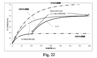
- FIG. 22 is a diagram showing a pattern in which the air in the tank is gradually increased by frequency control according to the first embodiment and 2
- FIG. 23 is a diagram showing a pattern in which the air in the tank is gradually increased by the pressure value using the pump of the first embodiment.
- a table is shown in the case where the drive frequency shown in FIG. 22 is switched and controlled so as to have the characteristic K4.
- FIG. 24 shows a table in the case where the pump of the second embodiment is used to switch the drive frequency shown in FIG. 22 with time to control the characteristic K4.
- the initial drive frequency is set to 300 Hz, 280 Hz, and 270 Hz, but this is an example, and the numerical value is not limited as long as it is a plurality of different frequencies.
- the frequency in the "frequency band (region) in which the flow rate is difficult to output" which is a frequency region higher than the second drive frequency H2 is used.
- the pump control system that controls the drive frequency of the current supplied to the coils 50a and 50b is used when the pressure increase time is extended, such as when the air pressure is to be gradually increased.
- a pump is used when it is necessary to send air gently when performing a blood vessel examination of an infant, tightening a belt to a subject, or the like.
- FIG. 25 is a diagram schematically showing a pump control system according to a third embodiment of the present invention.
- the pump control system shown in FIG. 25 is, for example, a blood pressure device 10D.
- the blood pressure device 10D includes a cuff 102 corresponding to a tank unit 120, a pipe unit 5 for sending air to the cuff, a pump drive unit 101, and a pressure measuring unit 13D.
- the drive unit 101 includes a resonance pump 1D, which is the pump 1 shown in FIG. 1, and a control unit 140 as a microcomputer unit.
- the control unit 140 which is a microcomputer unit, is connected to the resonance pump 1D and the pressure measurement unit 13D, and supplies a drive signal to the resonance pump 1D.
- the resonance pump 1D is driven according to the drive signal from the microcomputer unit 140.
- the pipe portion 5 is connected to the discharge portion 86 of the resonance pump 1D, and in the resonance pump 1D, the vibrating body 30 vibrates to drive the pump portion, and air can be suitably supplied to the cuff such as a sphygmomanometer test. .. Due to the configuration of the pump control system, it is possible to reduce the size, secure more suitable pump pressure and flow rate, and drive stably, and at the same time, the pressure inside the cuff can be adjusted to the desired pressure value in a short time. Can be increased up to.
- the pump according to the present invention can be miniaturized, can secure a more suitable pump pressure and flow rate, and has an effect of being able to be driven stably.
- the pump according to the present invention is useful as a wearable device for which thinning and high output are desired. Therefore, the present invention has industrial applicability.
Abstract
L'invention concerne un dispositif de commande de pompe destiné à commander une pompe (1) présentant un actionneur de vibration (10) qui fait vibrer un corps vibrant (30) par l'intermédiaire d'un entraînement électromagnétique par la fourniture de courant à des bobines (50a, 50b), une chambre étanche (82) qui présente une paroi mobile (822) qui est déplacée par vibration du corps vibrant (30), et dont le volume intérieur est modifié par déplacement de la paroi mobile (822) de sorte qu'un fluide est aspiré dans ou évacué depuis l'intérieur de celui-ci, et une section de décharge (86) qui est destinée à la communication fluidique entre la chambre étanche (82) et un réservoir (120) qui stocke le fluide déchargé à partir de la chambre étanche (82) et qui augmente la pression du fluide, ledit dispositif de commande de pompe présentant : une section d'acquisition (146) qui acquiert des informations de valeur de pression qui indiquent la pression du fluide dans le réservoir (120) ou une valeur correspondant à la pression ; et une section de commande (140) qui, sur la base des informations de valeur de pression acquises, commande la fréquence d'entraînement du courant fourni aux bobines (50a, 50b).
Priority Applications (4)
| Application Number | Priority Date | Filing Date | Title |
|---|---|---|---|
| CN202180025222.7A CN115349058A (zh) | 2020-03-31 | 2021-03-24 | 泵控制装置以及泵控制系统 |
| EP21780666.0A EP4112193A4 (fr) | 2020-03-31 | 2021-03-24 | Dispositif de commande de pompe et procédé de commande de pompe |
| US17/907,528 US20230147348A1 (en) | 2020-03-31 | 2021-03-24 | Pump control device and pump control system |
| JP2022512001A JPWO2021200423A1 (fr) | 2020-03-31 | 2021-03-24 |
Applications Claiming Priority (2)
| Application Number | Priority Date | Filing Date | Title |
|---|---|---|---|
| JP2020064576 | 2020-03-31 | ||
| JP2020-064576 | 2020-03-31 |
Publications (1)
| Publication Number | Publication Date |
|---|---|
| WO2021200423A1 true WO2021200423A1 (fr) | 2021-10-07 |
Family
ID=77928301
Family Applications (1)
| Application Number | Title | Priority Date | Filing Date |
|---|---|---|---|
| PCT/JP2021/012111 WO2021200423A1 (fr) | 2020-03-31 | 2021-03-24 | Dispositif de commande de pompe et procédé de commande de pompe |
Country Status (5)
| Country | Link |
|---|---|
| US (1) | US20230147348A1 (fr) |
| EP (1) | EP4112193A4 (fr) |
| JP (1) | JPWO2021200423A1 (fr) |
| CN (1) | CN115349058A (fr) |
| WO (1) | WO2021200423A1 (fr) |
Citations (6)
| Publication number | Priority date | Publication date | Assignee | Title |
|---|---|---|---|---|
| JPH0216379A (ja) * | 1988-06-30 | 1990-01-19 | Juki Corp | エアーポンプの駆動装置 |
| JPH0663879U (ja) * | 1993-02-22 | 1994-09-09 | 株式会社仲佐 | 振動式エアーポンプ |
| JP4396095B2 (ja) | 2002-06-03 | 2010-01-13 | セイコーエプソン株式会社 | ポンプ |
| JP2012135174A (ja) | 2010-12-24 | 2012-07-12 | Canon Inc | 振動型アクチュエータの制御装置 |
| JP2019075966A (ja) * | 2017-10-13 | 2019-05-16 | 孝仁 今川 | 往復運動モーター |
| JP2020006344A (ja) * | 2018-07-11 | 2020-01-16 | ミネベアミツミ株式会社 | 振動アクチュエーター及び電子機器 |
Family Cites Families (4)
| Publication number | Priority date | Publication date | Assignee | Title |
|---|---|---|---|---|
| JP5502017B2 (ja) * | 2011-04-15 | 2014-05-28 | 株式会社テクノ高槻 | 電磁振動型ダイヤフラムポンプ |
| JP5811766B2 (ja) * | 2011-10-26 | 2015-11-11 | オムロンヘルスケア株式会社 | 電子血圧計 |
| JP2013220321A (ja) * | 2012-04-19 | 2013-10-28 | Omron Healthcare Co Ltd | 血圧測定装置、血圧測定装置における制御装置、および、血圧測定装置の制御方法 |
| CN108071581B (zh) * | 2017-12-13 | 2019-07-05 | 深圳市景新浩科技有限公司 | 一种微型压电泵充气软件控制方法及系统 |
-
2021
- 2021-03-24 CN CN202180025222.7A patent/CN115349058A/zh active Pending
- 2021-03-24 US US17/907,528 patent/US20230147348A1/en active Pending
- 2021-03-24 JP JP2022512001A patent/JPWO2021200423A1/ja active Pending
- 2021-03-24 EP EP21780666.0A patent/EP4112193A4/fr active Pending
- 2021-03-24 WO PCT/JP2021/012111 patent/WO2021200423A1/fr unknown
Patent Citations (6)
| Publication number | Priority date | Publication date | Assignee | Title |
|---|---|---|---|---|
| JPH0216379A (ja) * | 1988-06-30 | 1990-01-19 | Juki Corp | エアーポンプの駆動装置 |
| JPH0663879U (ja) * | 1993-02-22 | 1994-09-09 | 株式会社仲佐 | 振動式エアーポンプ |
| JP4396095B2 (ja) | 2002-06-03 | 2010-01-13 | セイコーエプソン株式会社 | ポンプ |
| JP2012135174A (ja) | 2010-12-24 | 2012-07-12 | Canon Inc | 振動型アクチュエータの制御装置 |
| JP2019075966A (ja) * | 2017-10-13 | 2019-05-16 | 孝仁 今川 | 往復運動モーター |
| JP2020006344A (ja) * | 2018-07-11 | 2020-01-16 | ミネベアミツミ株式会社 | 振動アクチュエーター及び電子機器 |
Non-Patent Citations (1)
| Title |
|---|
| See also references of EP4112193A4 |
Also Published As
| Publication number | Publication date |
|---|---|
| CN115349058A (zh) | 2022-11-15 |
| EP4112193A1 (fr) | 2023-01-04 |
| JPWO2021200423A1 (fr) | 2021-10-07 |
| US20230147348A1 (en) | 2023-05-11 |
| EP4112193A4 (fr) | 2024-04-03 |
Similar Documents
| Publication | Publication Date | Title |
|---|---|---|
| US20140018713A1 (en) | Personal vibration appliance | |
| WO2006071719A2 (fr) | Dispositif de transfert d'energie d'entrainement reactionnel | |
| CN104373327B (zh) | 一种具有混合式电磁力弹簧的压电泵 | |
| JP2009529119A (ja) | 流体エネルギー伝達装置 | |
| JP2009529119A5 (fr) | ||
| US10615677B2 (en) | Actuator, air pump, beauty treatment device, and laser scanning device | |
| JP2003166471A (ja) | 往復動式圧縮機のピストン支持構造 | |
| KR101681588B1 (ko) | 왕복동식 압축기 | |
| WO2015045727A1 (fr) | Dispositif de commande de gaz | |
| WO2017049775A1 (fr) | Moteur miniature à commande auto-adaptative | |
| WO2021200423A1 (fr) | Dispositif de commande de pompe et procédé de commande de pompe | |
| JP2006029284A (ja) | エアーポンプ、生体押圧用吸排気装置及び電子血圧計 | |
| US20240084793A1 (en) | Pump system and electronics device | |
| WO2021200424A1 (fr) | Pompe et dispositif d'alimentation en air | |
| CN204200533U (zh) | 一种具有混合式电磁力弹簧的压电泵 | |
| CN114687985A (zh) | 泵系统、流体供给装置以及压力检测方法 | |
| CN114687986A (zh) | 泵系统、流体供给装置以及泵系统的驱动控制方法 | |
| JP2004092588A (ja) | ポンプ | |
| KR100428508B1 (ko) | 압축기 및 이의 제어방법 | |
| CN104781555B (zh) | 流体泵 | |
| JP2004251292A (ja) | 流体装置 | |
| US20060073039A1 (en) | Linear oscillating pressurizing device | |
| JPH11324927A (ja) | 磁石式小型ポンプ装置およびこれを用いた血圧計 | |
| CN117364408A (zh) | 一种洗涤设备的投放器的控制方法 | |
| JP5667528B2 (ja) | 自動血圧測定装置の排気弁 |
Legal Events
| Date | Code | Title | Description |
|---|---|---|---|
| 121 | Ep: the epo has been informed by wipo that ep was designated in this application |
Ref document number: 21780666 Country of ref document: EP Kind code of ref document: A1 |
|
| ENP | Entry into the national phase |
Ref document number: 2022512001 Country of ref document: JP Kind code of ref document: A |
|
| ENP | Entry into the national phase |
Ref document number: 2021780666 Country of ref document: EP Effective date: 20220928 |
|
| NENP | Non-entry into the national phase |
Ref country code: DE |