WO2021200423A1 - Pump control device and pump control system - Google Patents
Pump control device and pump control system Download PDFInfo
- Publication number
- WO2021200423A1 WO2021200423A1 PCT/JP2021/012111 JP2021012111W WO2021200423A1 WO 2021200423 A1 WO2021200423 A1 WO 2021200423A1 JP 2021012111 W JP2021012111 W JP 2021012111W WO 2021200423 A1 WO2021200423 A1 WO 2021200423A1
- Authority
- WO
- WIPO (PCT)
- Prior art keywords
- pump
- pressure
- tank
- fluid
- unit
- Prior art date
Links
- 239000012530 fluid Substances 0.000 claims abstract description 54
- 238000006073 displacement reaction Methods 0.000 claims abstract description 17
- 238000000034 method Methods 0.000 claims description 14
- 230000008569 process Effects 0.000 claims description 14
- 238000001514 detection method Methods 0.000 claims description 6
- 238000004891 communication Methods 0.000 abstract description 4
- 230000005291 magnetic effect Effects 0.000 description 86
- 238000010586 diagram Methods 0.000 description 33
- 238000003780 insertion Methods 0.000 description 8
- 230000037431 insertion Effects 0.000 description 8
- 230000008859 change Effects 0.000 description 6
- 230000036772 blood pressure Effects 0.000 description 5
- 239000000463 material Substances 0.000 description 5
- 230000004044 response Effects 0.000 description 5
- 238000005259 measurement Methods 0.000 description 4
- 238000009530 blood pressure measurement Methods 0.000 description 3
- 238000012545 processing Methods 0.000 description 3
- 206010020772 Hypertension Diseases 0.000 description 2
- 229910000576 Laminated steel Inorganic materials 0.000 description 2
- 230000009471 action Effects 0.000 description 2
- 230000007423 decrease Effects 0.000 description 2
- 230000000694 effects Effects 0.000 description 2
- 239000000696 magnetic material Substances 0.000 description 2
- 238000005192 partition Methods 0.000 description 2
- 230000000630 rising effect Effects 0.000 description 2
- XEEYBQQBJWHFJM-UHFFFAOYSA-N Iron Chemical group [Fe] XEEYBQQBJWHFJM-UHFFFAOYSA-N 0.000 description 1
- 229910000831 Steel Inorganic materials 0.000 description 1
- 238000007792 addition Methods 0.000 description 1
- 210000004204 blood vessel Anatomy 0.000 description 1
- 230000006835 compression Effects 0.000 description 1
- 238000007906 compression Methods 0.000 description 1
- 239000000470 constituent Substances 0.000 description 1
- 238000013016 damping Methods 0.000 description 1
- 238000007599 discharging Methods 0.000 description 1
- 239000013013 elastic material Substances 0.000 description 1
- 239000003302 ferromagnetic material Substances 0.000 description 1
- 230000014509 gene expression Effects 0.000 description 1
- 238000002347 injection Methods 0.000 description 1
- 239000007924 injection Substances 0.000 description 1
- 238000010030 laminating Methods 0.000 description 1
- 230000005389 magnetism Effects 0.000 description 1
- 239000002184 metal Substances 0.000 description 1
- 229910052751 metal Inorganic materials 0.000 description 1
- 239000007769 metal material Substances 0.000 description 1
- 230000007935 neutral effect Effects 0.000 description 1
- 230000009467 reduction Effects 0.000 description 1
- 239000011347 resin Substances 0.000 description 1
- 229920005989 resin Polymers 0.000 description 1
- 229910001220 stainless steel Inorganic materials 0.000 description 1
- 239000010935 stainless steel Substances 0.000 description 1
- 239000010959 steel Substances 0.000 description 1
- 238000012360 testing method Methods 0.000 description 1
Images


Classifications
-
- B—PERFORMING OPERATIONS; TRANSPORTING
- B06—GENERATING OR TRANSMITTING MECHANICAL VIBRATIONS IN GENERAL
- B06B—METHODS OR APPARATUS FOR GENERATING OR TRANSMITTING MECHANICAL VIBRATIONS OF INFRASONIC, SONIC, OR ULTRASONIC FREQUENCY, e.g. FOR PERFORMING MECHANICAL WORK IN GENERAL
- B06B1/00—Methods or apparatus for generating mechanical vibrations of infrasonic, sonic, or ultrasonic frequency
- B06B1/02—Methods or apparatus for generating mechanical vibrations of infrasonic, sonic, or ultrasonic frequency making use of electrical energy
- B06B1/04—Methods or apparatus for generating mechanical vibrations of infrasonic, sonic, or ultrasonic frequency making use of electrical energy operating with electromagnetism
- B06B1/045—Methods or apparatus for generating mechanical vibrations of infrasonic, sonic, or ultrasonic frequency making use of electrical energy operating with electromagnetism using vibrating magnet, armature or coil system
-
- F—MECHANICAL ENGINEERING; LIGHTING; HEATING; WEAPONS; BLASTING
- F04—POSITIVE - DISPLACEMENT MACHINES FOR LIQUIDS; PUMPS FOR LIQUIDS OR ELASTIC FLUIDS
- F04B—POSITIVE-DISPLACEMENT MACHINES FOR LIQUIDS; PUMPS
- F04B45/00—Pumps or pumping installations having flexible working members and specially adapted for elastic fluids
- F04B45/04—Pumps or pumping installations having flexible working members and specially adapted for elastic fluids having plate-like flexible members, e.g. diaphragms
- F04B45/047—Pumps having electric drive
-
- A—HUMAN NECESSITIES
- A61—MEDICAL OR VETERINARY SCIENCE; HYGIENE
- A61B—DIAGNOSIS; SURGERY; IDENTIFICATION
- A61B5/00—Measuring for diagnostic purposes; Identification of persons
- A61B5/0048—Detecting, measuring or recording by applying mechanical forces or stimuli
- A61B5/0051—Detecting, measuring or recording by applying mechanical forces or stimuli by applying vibrations
-
- A—HUMAN NECESSITIES
- A61—MEDICAL OR VETERINARY SCIENCE; HYGIENE
- A61B—DIAGNOSIS; SURGERY; IDENTIFICATION
- A61B5/00—Measuring for diagnostic purposes; Identification of persons
- A61B5/02—Detecting, measuring or recording pulse, heart rate, blood pressure or blood flow; Combined pulse/heart-rate/blood pressure determination; Evaluating a cardiovascular condition not otherwise provided for, e.g. using combinations of techniques provided for in this group with electrocardiography or electroauscultation; Heart catheters for measuring blood pressure
- A61B5/021—Measuring pressure in heart or blood vessels
- A61B5/022—Measuring pressure in heart or blood vessels by applying pressure to close blood vessels, e.g. against the skin; Ophthalmodynamometers
Definitions
- the present invention relates to a control device, and more particularly to a pump control device using a vibration actuator that is driven by resonance.
- a movable wall such as a piston or a diaphragm is displaced by an actuator, and the volume of the pump chamber is changed by the displacement of the movable wall, so that the working fluid flows into the pump chamber and the working fluid flows from the pump chamber. Outflow.
- the motion cycle of the movable wall itself is changed according to the displacement time, the amount of displacement, or the displacement speed of the movable wall in the pump chamber volume compression stroke.
- a fluctuation imparting means that gives a predetermined fluctuation to one or more parameters of a frequency, an amplitude, and a phase in an AC voltage applied to a vibrating body, and a fluctuation that is output by the fluctuation imparting means.
- a frequency response characteristic measuring means for obtaining a frequency response characteristic at one or more predetermined frequencies is provided, which outputs a physical quantity that changes according to the vibration of the vibrating body.
- the frequency range of the AC voltage output by the AC voltage generating means is controlled according to the estimated value of the resonance frequency output from the resonance frequency estimating means.
- the pump device be miniaturized and have a large pump pressure and flow rate.
- the measuring unit for measuring the displacement amount or the displacement speed of the movable wall. Need to be installed in the pump.
- the measuring unit is provided in the pump, there is a problem that it is difficult to reduce the size in order to secure the arrangement space.
- the process of obtaining the frequency response characteristic at one or more predetermined frequencies with respect to the physical quantity that changes according to the vibration of the vibrating body, and the processing of the vibrating body that changes according to the parameter change of the driving voltage There is a problem that it takes time to control because it involves a process of estimating the resonance frequency.
- the present invention has been made in view of the above points, and it is intended to provide a pump control device and a pump control system which can be miniaturized, can secure a more suitable pump pressure and flow rate, and can be stably driven. The purpose.
- a vibrating actuator that vibrates the vibrating body by electromagnetic drive by supplying an electric current to the coil
- a closed chamber having a movable wall that is displaced by the vibration of the vibrating body, and a fluid is sucked into or discharged from the inside by changing the internal volume due to the displacement of the movable wall.
- a discharge unit for communicating the fluid between the tank for collecting the fluid discharged from the closed chamber and increasing the pressure of the fluid and the closed chamber.
- It is a pump control device for controlling a pump having An acquisition unit that acquires pressure value information indicating a pressure value of the fluid in the tank or a value corresponding to the pressure.
- a pump control device including a control unit that controls a drive frequency of a current supplied to the coil based on the acquired pressure value information.
- the control unit controls the drive frequency so that the current is supplied to the coil at the resonance frequency of the vibrating body, which differs depending on the pressure of the fluid in the tank.
- the pump control device according to 1).
- the control unit is between a first drive frequency that maximizes the flow rate of the fluid from the pump to the tank and a second drive frequency that maximizes the pressure of the fluid in the tank.
- the pump control device according to (2) above which switches the drive frequency.
- the acquisition unit is a pump control system that acquires the pressure value information from the pressure detection unit.
- the acquisition unit is a pump control system that acquires the pressure value information from the timer.
- the pump control device has a storage unit that stores a table showing a relationship between a preset drive time of the vibrating body and the pressure of the fluid in the tank that increases due to the drive time drive.
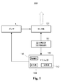
- FIG. 1 is a block diagram showing a schematic configuration of a pump control system according to a first embodiment of the present invention.
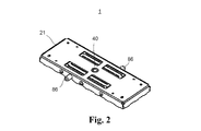
- FIG. 2 is an external perspective view of the pump of the pump control system according to the first embodiment of the present invention.
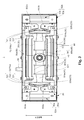
- FIG. 3 is a plan view showing a configuration of a main part of a pump of the pump control system according to the first embodiment of the present invention.
- FIG. 4 is an exploded perspective view of the pump of the pump control system according to the first embodiment of the present invention.
- FIG. 5 is a perspective view of a coil core portion of the pump of the pump control system according to the first embodiment of the present invention.
- FIG. 6 is a perspective view of a vibrating body in the pump of the pump control system according to the first embodiment of the present invention.
- FIG. 7 is a plan sectional view showing an internal configuration of a pump of the pump control system according to the first embodiment of the present invention.
- FIG. 8 is an exploded perspective view of a pump portion of the pump of the pump control system according to the first embodiment of the present invention.
- FIG. 9 is a diagram showing an air flow path of the pump portion of the pump of the pump control system according to the first embodiment of the present invention.
- 10A and 10B are diagrams showing an air discharge / suction operation in the pump of the control system pump according to the first embodiment of the present invention.
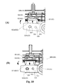
- FIG. 11 is a diagram showing a magnetic spring of the pump of the pump control system according to the first embodiment of the present invention.
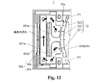
- FIG. 12 is a diagram showing a magnetic circuit configuration of a pump of the pump control system according to the first embodiment of the present invention.
- FIG. 13 is a diagram showing the operating principle of the pump.
- FIG. 14 is a diagram showing the frequency characteristics of the pressure of the air in the tank portion when the pump is open and when the pump is closed when the resonance type pump of the present embodiment is used.
- FIG. 15 is a diagram showing an example of frequency control in the pump control system according to the embodiment of the present invention.
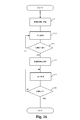
- FIG. 16 is a diagram showing a frequency control flow of the pump control system according to the embodiment of the present invention.
- FIG. 17 is a block diagram showing a schematic configuration of a pump control system according to a second embodiment of the present invention.
- FIG. 18 is a diagram showing a pattern of drive frequency control when the tank capacities are different.
- FIG. 19 is a diagram showing a pattern of drive frequency control when the tank capacities are different.
- FIG. 20 is a diagram showing a table in the case where the drive frequency is switched by the pressure value using the pump control system of the first embodiment.
- 21A and 21B are diagrams showing a table in the case of switching the drive frequency with time using the pump control system of the second embodiment.
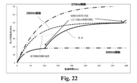
- FIG. 22 is a diagram showing a frequency control pattern according to the first embodiment and the second embodiment.
- FIG. 23 is a diagram showing a table in the case where the drive frequency is switched by the pressure value using the control system pump of the first embodiment.
- FIG. 24 is a diagram showing a table in the case of switching the drive frequency with time using the control system pump of the second embodiment.
- FIG. 25 is a diagram schematically showing a pump control system according to a third embodiment of the present invention.
- FIG. 1 is a block diagram showing a schematic configuration of a pump control system 100 according to an embodiment of the present invention.
- the pump control system 100 includes a pump 1, a tank unit 120, a pressure measuring unit (pressure detecting unit) 130, and a microcomputer unit (control unit) 140.
- the pump control system 100 is capable of outputting the fluid discharged from the pump 1, the air (gas) in the present embodiment, by adjusting the pressure in the tank unit 120.
- the frequency of the pump 1 is controlled by the drive signal (current supply) output from the microcomputer unit 140. Specifically, a drive signal having a resonance frequency is input to the vibration actuator constituting the pump 1 to electromagnetically drive the vibration actuator, and supply air as a fluid to the tank unit 120.
- a drive signal having a resonance frequency is input to the vibration actuator constituting the pump 1 to electromagnetically drive the vibration actuator, and supply air as a fluid to the tank unit 120.
- FIG. 2 is an external perspective view of the pump portion of the pump of the pump control system according to the first embodiment of the present invention.
- FIG. 3 is a plan view showing a configuration of a main part of a pump of the pump control system according to the first embodiment of the present invention.
- FIG. 4 is an exploded perspective view of the pump of the pump control system according to the first embodiment of the present invention.
- FIG. 5 is a perspective view of a coil core portion of the pump of the pump control system according to the first embodiment of the present invention.
- FIG. 6 is a perspective view of a vibrating body in the pump of the pump control system according to the first embodiment of the present invention.
- FIG. 7 is a plan sectional view showing an internal configuration of a pump of the pump control system according to the first embodiment of the present invention.
- FIG. 8 is an exploded perspective view of a pump portion of the pump of the pump control system according to the first embodiment of the present invention.
- the vibration direction of the vibrating body that reciprocates in the vibration actuator of the pump in the pump control system is the direction shown in FIG.
- the two directions orthogonal to this direction will be described as a lateral direction (horizontal direction) and a height direction (vertical direction, also referred to as a thickness direction), respectively.
- expressions indicating directions such as left / right (horizontal) and height (up / down) used to explain the configuration and operation of each part of the pump 1 are not absolute but relative. It is appropriate when each part of the pump is in the posture shown in the figure, but when the posture changes, it should be changed and interpreted according to the change in the posture.
- the pump 1 shown in FIGS. 2 and 3 discharges air by the action of an electromagnetically driven vibration actuator 10.
- the pump has been described as discharging and sucking air, but what is discharged and sucked by the pump is not limited to air, but may be a fluid, and a gas is particularly preferable.
- the height (length in the vertical direction in the drawing and corresponding to the thickness) of the pump 1 is horizontal (horizontal direction in the drawing) and vertical (depth direction in the drawing and vibration). It has a flat plate shape that is shorter than both directions. Also, the length is shorter than the width. Note that FIG. 2 is a perspective view of the pump 1 as viewed from the back surface side.
- the pump 1 includes a vibrating actuator 10 in which a vibrating body (movable body) 30 is reciprocally rotatably provided with respect to a fixed body 20 via a shaft portion 40, and a pump portion 80 that discharges and sucks air by driving the vibrating actuator 10. (80a, 80b) and.
- the vibrating body 30 is rotatably provided in the case 21 of the fixed body 20 via the shaft portion 40.
- the vibrating body 30 moves in the axial direction of the shaft portion 40 with respect to the fixed body 20. It reciprocates along, that is, it vibrates.
- the pump 1 can discharge and suck air from the discharge unit 86 by utilizing the vibration of the vibrating body 30.
- a vibrating body 30 is provided in a case 21 having a rectangular shape in a plan view so as to be reciprocally rotatable around a shaft portion 40 arranged at the center thereof.
- the magnets 70a and 70b are provided on the inner surfaces of both end wall portions that are separated from each other in the longitudinal direction of the vibrating body 30.
- the coil core portion 62a including the coil 50a and the core portion 60a is provided on the inner surface of the end wall portion of the case 21 on the side facing the magnet 70a, and the coil core portion 62b including the coil 50b and the core portion 60b faces the magnet 70b. It is provided on the inner surface of the end wall portion of the case 21 on the side of the coil.
- the magnets 70a and 70b are preferably permanent magnets, for example.
- the vibrating actuator 10 includes a fixed body 20, a shaft portion 40, and a vibrating body 30 that is rotatably supported with respect to the fixed body 20 via the shaft portion 40.
- the vibrating actuator 10 is provided with magnets 70 (70a, 70b) on one of the fixed body 20 and the vibrating body 30, and the magnetized surface of the core faces the magnet 70 on the other side of the fixed body 20 and the vibrating body 30.
- Coil core portions 62 (62a, 62b) arranged so as to be provided are provided.
- the vibrating body 30 is provided with magnets 70 (70a, 70b), and the fixed body 20 is provided with coil core portions 62 (62a, 62b).
- the vibrating body 30 includes magnets 70 (70a, 70b), and the fixed body 20 includes coil core portions 62 (62a, 62b).
- the vibrating actuator 10 electromagnetically drives the vibrating body 30 by supplying an electric current to the coils 50a and 50b, and vibrates the vibrating body 30 which is a vibrating body.
- the fixed body 20 has a case 21, a cover 22, and coil core portions 62a and 62b. Further, the fixed body 20 is provided with pump portions 80 (80a, 80b).
- the case 21 functions as a housing for the pump 1 and has a rectangular box shape that opens on one side.
- a shaft portion 40 is erected in the case 21, and rotatably supports the vibrating body 30 arranged in the case 21.
- the coil core portions 62a and 62b are arranged on the inner surfaces of the both end wall portions separated in the longitudinal direction of the case 21 so as to face the magnets 70a and 70b of the vibrating body 30, respectively.
- the opening portion of the case 21, in the present embodiment, the opening portion that opens upward is covered with the cover 22.
- the case 21 and the cover 22 function as a hollow electromagnetic shield, and the pump 1 has a flat plate shape.
- the shaft portion 40 is provided on the bottom surface of the case 21 at the center of the case 21 in the lateral direction and the depth direction so as to extend in the height direction of the case 21.
- the shaft portion 40 is fitted and fixed to the shaft hole 23 of the cover 22 by press fitting or adhesion after insertion in a state of being inserted into the bearing portion 34 of the vibrating body 30.
- the shaft portion 40 is supported in a state of being inserted into the bearing portion 34 of the vibrating body 30 and erected on the bottom surface of the case 21 and the cover 22.
- the coil core portions 62a and 62b are arranged to face each other on the inner surfaces of both end wall portions separated in the longitudinal direction in the case 21. Further, the coil core portions 62a and 62b are arranged so as to sandwich the vibrating body 30 in the longitudinal direction of the case 21.
- the coil core portions 62a and 62b are similarly configured in this embodiment, and are provided at positions symmetrical with respect to the axis of the shaft portion 40 in a plan view.
- the core portions 60a and 60b are magnetic materials that are magnetized by energizing the coils 50a and 50b.
- the core portions 60a and 60b may be made of, for example, electromagnetic stainless steel, a sintered material, a MIM (metal injection mold) material, a laminated steel plate, an electrogalvanized steel plate (SECC), or the like.
- the core portions 60a and 60b are composed of laminated cores made of laminated steel plates.
- the core portions 60a and 60b are magnetic poles (hereinafter, for convenience, referred to as "core magnetic poles") 602a formed continuously at both ends of the cores 601a and 601b around which the coils 50a and 50b are wound and both ends of the cores 601a and 601b. , 603a, 602b, 603b.
- each of the core magnetic poles 602a, 603a, 602b, and 603b has a curved magnetic pole surface having an arc shape in a plan view according to the magnetized surface shape of the reciprocating rotating magnets 70a and 70b.
- the core magnetic poles 602a and 603a of the core portion 60a face the magnet 70a, and the core magnetic poles 602b and 603b of the core portion 60b face the magnet 70b.
- the core magnetic poles 602a, 603a, 602b, and 603b are arranged side by side in the rotation direction of the reciprocating rotation of the vibrating body 30.
- the core magnetic poles 602a, 603a, 602b, and 603b are preferably arranged on the circumference of a circle centered on the shaft portion 40. This circumference is a circumference along the motion trajectory of the magnets 70a and 70b.
- the core magnetic poles 602a, 603a, 602b and 603b of the core portions 60a and 60b around which the coils 50a and 50b are wound are arranged so as to face the magnetizing direction of the magnets 70a and 70b.
- the coils 50a and 50b are connected to, for example, a power supply unit (not shown) in each of the core units 60a and 60b.
- the coils 50a and 50b excite the core magnetic poles 602a, 603a, 602b and 603b by supplying power from the power supply unit.
- the core magnetic poles 602a and 602b and the core magnetic poles 603a and 603b are excited with different polarities.
- the vibrating body 30 has a direction (longitudinal direction of the case 21) orthogonal to the shaft portion 40 (rotating axis of the vibrating body 30) in the case 21 of the fixed body 20. ) Extends and is placed.
- the vibrating body 30 is rotatably supported in the case 21 around the shaft portion 40.
- the vibrating body 30 presses the vibrating body body 32, the bearing portion 34, and a pair of magnets 70a and 70b in which a plurality of magnetic poles (three poles in this embodiment) are alternately arranged in the rotation direction (depth direction). It has a part 35 and.
- a bearing portion 34 is fixed to the vibrating body main body 32, and a shaft portion 40 is inserted through the bearing portion 34.
- a pair of magnets 70a and 70b are fixed to the vibrating body main body 32 so as to sandwich the shaft portion 40 inserted via the bearing portion 34.
- the vibrating body 32 may or may not be a magnetic body (ferromagnetic material), is a yoke in the present embodiment, and functions as a weight of the vibrating body 30.
- the vibrating body body 32 is configured by, for example, laminating yoke iron cores.
- the constituent material of the vibrating body 32 is not limited to the metal material, and a resin material or the like may be used.
- the vibrating body 32 has a central opening 322 to which the bearing portion 34 is fixed in the central portion, and arm portions 324a and 324b extending in opposite directions from the central portion.
- the arm portions 324a and 324b have an elongated flat plate shape, and their respective tip portions are formed so as to project in a direction intersecting the extending direction. Further, magnet fixing portions 326a and 326b are formed on the tip surfaces of the arm portions 324a and 324b.
- the tip surfaces of the magnet fixing portions 326a and 326b are formed by being curved in an arc shape, and the magnets 70a and 70b are fixed to the tip surfaces. Further, the arm portions 324a and 324b are provided with a pressing portion 35.
- Magnetics 70a, 70b The magnets 70a and 70b, together with the coil core portions 62a and 62b arranged to face each other, form a magnetic circuit for driving the vibration actuator 10.
- the magnets 70a and 70b have magnetic pole surfaces 72 that function as a plurality of magnetic poles, and the magnetic pole surfaces 72 of the magnet 70a and the magnetic pole surfaces 72 of the magnet 70b are arranged so as to face opposite to each other with the shaft portion 40 interposed therebetween.
- the magnets 70a and 70b are separated from each other in the extending direction of the vibrating body body 32 into which the shaft portion 40 is inserted at the central portion, that is, at the tip portions of both arm portions 324a and 324b, respectively.
- the magnetic pole surface 72 is provided so as to face outward.
- the magnetic pole surface 72 includes three different magnetic poles 721, 722, and 723 that are alternately arranged, as shown in FIGS. 3-7 and 11.
- the magnets 70a and 70b may be configured by alternately arranging a plurality of magnets (magnet pieces) having different magnetic poles, or may be magnetized so as to be arranged in the rotation direction and have different magnetisms alternately.
- the magnets 70a and 70b are composed of, for example, an Nd sintered magnet or the like.
- the magnetic poles 721, 722, and 723 of the magnets 70a and 70b are arranged adjacent to each other in the depth direction, that is, in the rotation direction, which sandwiches the shaft portion 40 and is orthogonal to the axis of the shaft portion 40.
- the magnets 70a and 70b are arranged at both ends of the vibrating body 30 so that the magnetic pole surfaces 72 are located on the circumference of a circle centered on the shaft portion 40.
- the magnets 70a and 70b are in a normal state, that is, in a non-energized state in which no current is supplied to the coils 50a and 50b, the central position of the length of the central magnetic pole 722 of the respective magnetic pole surfaces 72 in the rotational direction is , Is provided so as to be located at the center position between the core magnetic poles 602a and 603a.
- the magnets 70a and 70b are placed on the inner surfaces of both end walls of the housing (case 21) at positions most distant from each other in the vibrating body 30 via the shaft portions 40 and the arm portions 324a and 324b. It is arranged so as to face each of the coil core portions 62a and 62b provided respectively.
- the pressing portion 35 presses the movable wall 822 of the pair of closed chambers 82 of the pump portion 80 when the vibrating body 30 rotates and moves.
- the pressing portion 35 has a pair of pressing elements 351 that press the movable walls 822 of the pair of closed chambers 82 when the arm portions 324a and 324b reciprocate.
- the pair of pressers 351 of the pressing portion 35 are provided on the arm portions 324a and 324b so as to project in the width direction, that is, in the rotation direction.
- the pressing portion 35 may be formed so as to linearly press the movable wall 822 in the opposite direction even when the vibrating body 30 rotates, for example.
- each presser 351 of the pressing portion 35 moves in an arc shape around the shaft portion 40, abuts on the movable wall 822, and presses the movable wall 822.
- the pressing portion 35 may be configured in any configuration as long as it is displaced toward the movable wall side and presses the movable wall 822 to move the movable wall 822 with the rotational movement of the vibrating body 30. It is desirable that the movable wall 822 is arranged so as to intersect the moving path of the pressing portion 35, and the moving pressing portion 35 is arranged so as to be in surface contact with the movable wall 822.
- the pressing portion 35 has arm portions 324a and 324b via a shaft protrusion 353 rotatably attached to the round hole 328 and a guide protrusion 352 guided to the elongated hole 329. It is fixed for each of.
- the presser 351 swings in an arc shape as the vibrating body 30 reciprocates.
- the guide protrusion 352 is loosely fitted in the elongated hole 329, and the pressing portion 35 can swing with respect to the arm portions 324a and 324b by the guide protrusion 352, so that the tip of the presser 351 can swing. You may.
- the pressing portion 35 moves in an arc shape, but the pressing element 351 can be linearly moved with respect to the movable wall 822 to be pressed.
- the pressing portion 35 is connected to the movable wall 822 of the pump portion 80 via the pressing element 351.
- the presser 351 is inserted into the insertion portion 822a of the movable wall 822, which is a diaphragm, and presses and displaces the movable wall 822 in the rotational direction.
- the pressing portion 35 presses the movable wall 822 when it moves to the movable wall 822 side due to the rotation of the vibrating body 30.
- the bearing portion 34 is formed of, for example, a sintered sleeve bearing.
- the bearing portion 34 is fitted to the central opening 322 of the vibrating body main body 32 so that the shaft portion 40 is located on the central axis of the vibrating body main body 32.
- the vibrating body 32 When the coil 50a and 50b are not fed, the vibrating body 32 is positioned at the center in the longitudinal direction in the case 21 (fixed body 20) by the function of the magnetic spring by the core portions 60a and 60 and the magnets 70a and 70b. Be urged to do.
- Each of the pump portions 80 (80a, 80b) has a movable wall 822, a closed chamber 82 defined by the movable wall 822, a suction portion 83, a valve 84, a discharge portion 86, and a discharge flow path portion 88.
- the movable wall 822 constitutes a wall portion that separates the chamber forming portion 824 and the discharge flow path portion 88, and is provided so as to be displaceable.
- the movable wall 822 changes the volume in the closed chamber 82 by being displaced by the vibration of the vibrating body 30.
- the movable wall 822 and the chamber forming portion 824 form a closed chamber 82.
- the movable wall 822 is formed of, for example, an elastically deformable material, and is provided so as to close the chamber forming portion 824.
- the movable wall 822 is, for example, a diaphragm.
- the movable wall 822 has an insertion portion 822a into which the pressing element 351 of the pressing portion 35 is inserted, and is connected to the pressing portion 35 via the insertion portion 822a.
- the movable wall 822 is pressed and displaced by the pressing portion 35 that moves with the rotation of the vibrating body 30.
- the movable wall 822 is elastically deformed by being pressed toward the chamber forming portion 824 by the pressing portion 35 via the insertion portion 822a, and is deformed so that the volume of the chamber forming portion 824 is reduced.
- the volume of the closed chamber 82 can be changed by displacing the movable wall 822 toward the chamber forming portion 824 and projecting into the chamber forming portion 824.
- the movable wall 822 is inserted into the chamber forming portion 824 by the forward rotation movement of the reciprocating rotation of the vibrating body 30 (swinging to one side in the rotation direction), presses the inside of the chamber forming portion 824, and is inside the closed chamber 82. Reduce capacity and expel air. On the other hand, when the vibrating body 30 revolves (moves to the other side in the rotation direction), the movable wall 822 increases the capacity in the closed chamber 82 and allows air to flow in.
- the closed chamber 82 is a closed space in which the suction unit 83 and the discharge unit 86 are connected and the volume is changed by the displacement of the movable wall 822.
- the discharge unit 86 has a discharge port that communicates with the outside, and discharges air from the pump 1 to the outside through the discharge port.
- the discharge port is an opening that communicates with the discharge portion 86 connected to the bottom surface of the closed chamber 82.
- the movable wall 822 when the movable wall 822 is pressed by the pressing unit 35, the movable wall 822 elastically deforms toward the inside of the closed chamber 82 and presses the air in the closed chamber 82.
- the pressed air in the closed chamber 82 is discharged to the outside via the discharge unit 86.
- the suction portion 83 is moved into the closed chamber 82. Air is sucked in from the outside through.
- the suction unit 83 has a suction port and sucks air into the closed chamber 82 through the suction port.
- the suction port is an opening communicating with the suction section 83 in the chamber forming section 824.
- the pump portions 80 (80a, 80b) are respectively arranged in the case 21 along the extending direction of the vibrating body 30, that is, the side wall portion extending in the longitudinal direction of the case 21. Further, the pump portions 80 (80a, 80b) are arranged so as to sandwich the vibrating body body 32 of the vibrating body 30 in the depth direction of the case 21.
- the pump section 80 includes, for example, a base 801, a diaphragm section 802, a cylinder section 803, a valve section 804, a valve cover section 805, a partition section 806, and a flow path forming section 807.
- the base 801 and the diaphragm portion 802, the cylinder portion 803, the valve portion 804, the valve cover portion 805, the partition portion 806, and the flow path forming portion 807 each have an elongated plate shape extending in the longitudinal direction of the case 21.
- a pump portion 80 having a sealed internal space is formed by being laminated.
- the base 801 has an opening, and the insertion portion 822a of the diaphragm portion 802 is inserted from the back side into the opening, and the insertion portion 822a is arranged in a state of projecting to the front side.
- the base 801 and the flow path forming portion 807 form a housing of the strip-shaped pump portion 80.
- the diaphragm portion 802 is formed of an elastic material such as rubber.
- the diaphragm portion 802 has an insertion portion 822a and a movable wall 822.
- a chamber forming portion 824 of the cylinder portion 803 is arranged on the back surface side of the movable wall 822 that is flexible and elastically deformed.
- the diaphragm portion 802 and the cylinder portion 803 are attached to each other so that the movable wall 822 of the diaphragm portion 802 and the chamber forming portion 824 of the cylinder portion 803 form a closed chamber 82 which is a closed space.
- the cylinder portion 803 has a chamber forming portion 824, and in the closed chamber 82, two communication holes communicating with the discharge portion 86 and the suction portion 83 are formed on the surface facing the movable wall 822.
- the two communication holes are formed from the back side of the cylinder portion 803 via the valve 84 of the valve portion 804 attached so as to overlap the communication holes, respectively, and the discharge flow path portions of the valve cover portion 805 and the flow path forming portion 807, respectively. It is connected to 88 and the suction unit 83.
- the valve portion 804 is attached to the valve cover portion 805.
- the valve 84 connected to the discharge portion 86 is configured to communicate with the discharge portion 86 of the flow path forming portion 807 when the capacity in the closed chamber 82 decreases.
- the valve 84 connected to the discharge portion 86 is configured to close when the capacity in the closed chamber 82 increases.
- the valve 84 connected to the suction unit 83 is configured to close when the capacity in the closed chamber 82 decreases.
- the valve 84 connected to the suction unit 83 is configured to communicate with the suction unit 83 of the flow path forming unit 807 when the capacity of the closed chamber 82 increases.
- each of the pump portions 80 has a pair of closed chambers 82 including a movable wall 822 and a chamber forming portion 824.
- Each of the pump portions 80 (80a, 80b) is arranged such that its pair of closed chambers 82 face each side surface of the arm portions 324a and 324b extending in opposite directions with the shaft portion 40 in between. There is. That is, the pump portion 80 (80a, 80b) is at a position where the pair of closed chambers 82 of the pump portion 80 (80a, 80b) sandwich the arm portions 324a and 324b in the direction in which the arm portions 324a and 324b reciprocate and rotate. And they are arranged so as to face each other.
- FIGS. 10A and 10B are diagrams showing an air discharge / suction operation in the pump of the pump control system according to the first embodiment of the present invention.
- the magnets 70a and 70b arranged at both ends of the vibrating body 30 facing each other with the vibrating body shaft portion 40 sandwiching the vibrating body shaft portion 40 in the case 21 are longitudinally provided with each of the magnets 70a and 70b.
- the core portions 60a and 60b, which are magnetic materials, are arranged so as to face each other so as to be separated from each other in the direction.
- the core portions 60a and 60b are respectively arranged on the inner surfaces of both end wall portions in the longitudinal direction of the case 21 so as to be separated from each other in the longitudinal direction and face each other.
- Magnetic attraction is generated between the core portion 60a and the magnet 70a, and between the core portion 60b and the magnet 70b, respectively.
- the two magnetic attraction forces generated in the longitudinal direction are generated on the same straight line and in opposite directions with the shaft portion 40 in between, so that they cancel each other out.
- FIG. 11 is a diagram showing a magnetic spring of the pump of the pump control system according to the first embodiment of the present invention.
- the magnetic circuit provided by the coil core portion 62a and the magnet 70a and the magnetic circuit provided by the coil core portion 62b and the magnet 70b are point-symmetrically configured around the shaft portion 40. Therefore, in FIG. 11, only the magnetic circuit provided by the coil core portion 62a and the magnet 70a will be described, and the description of the magnetic circuit provided by the coil core portion 62b and the magnet 70b will be omitted.
- the magnet 70a has a configuration in which the magnetic poles 721, 722, and 723 are N poles, S poles, and N poles, respectively, on the magnetic pole surface 72 facing the core portion 60a.
- the magnetic poles 721 to 723 on the magnetic pole surface 72 of the magnet 70a attract the core magnetic poles 602a and 603a, which are close to each other, respectively.
- the central magnetic pole 722 of the magnet 70a attracts both the core magnetic poles 602a and 603a.
- the magnetic pole 721 of the magnet 70a attracts the core magnetic pole 602a, and the magnetic pole 723 of the magnet 70a attracts the core magnetic pole 603a.
- the magnetic pole 722 at the center of the magnet 70a is located between the central portion of the coil core portion 62a, that is, the core magnetic poles 602a and 603a.
- the vibrating body 30 including the magnets 70a and 70b rotates and reciprocates (rotationally reciprocating vibration) in the rotational direction around the shaft portion 40. ..
- FIG. 12 is a diagram showing a magnetic circuit configuration of a pump of the pump control system 100 according to the first embodiment of the present invention.
- the magnetic circuit provided by the coil core portion 62a and the magnet 70a will be described as in the description with reference to FIG. 11, and the coil core portion 62b and the magnet 70b will be described.
- the description of the magnetic circuit provided by the above will be omitted.
- the magnet 70a has three polar poles arranged alternately in the rotation direction of the vibrating body 30 on the magnetic pole surface 72.
- the central magnetic pole 722 is the S pole
- the magnetic poles 721 and 723 sandwiching the central magnetic pole 722 are the N poles, respectively.
- the magnetic pole 723 of the magnet 70a facing the core magnetic pole 603a which is the north pole is the north pole, it repels the core magnetic pole 603a which is the north pole.
- the magnetic pole 722 of the magnet 70a is the S pole, a magnetic attraction force is generated between the magnetic pole 722 and the core magnetic pole 603a which is the N pole, but repels the core magnetic pole 602a which is the S pole.
- the magnetic pole 721 of the magnet 70a is the N pole, a magnetic attraction force is generated between the magnetic pole 721 and the core magnetic pole 602a which is the S pole.
- a current is supplied to the coil 50a in the opposite direction to reverse the polarity of the core portion 60a, that is, the magnetic pole 603a of the core portion 60a facing the magnet 70a is set to the S pole and the magnetic pole 602a is set to the N pole.
- the magnet 70a facing the core portion 60a rotates and moves in the direction opposite to the F1 direction ( ⁇ F1 direction).
- the vibrating body 30 is driven in the ⁇ F1 direction, which is the opposite of the F1 direction.
- the relationship between the magnet 70b arranged on the opposite side of the magnet 70a across the shaft portion 40 and the coil core portion 62b is centered on the shaft portion 40 with respect to the relationship between the magnet 70a and the coil core portion 62a. It becomes point symmetric. Therefore, between the magnet 70b and the coil core portion 62b, a thrust in the F1 direction or the ⁇ F1 direction is similarly generated between the magnet 70a and the coil core portion 62a.
- the vibrating body 30 preferably rotates and reciprocates around the shaft portion 40 due to the magnetic attraction force and the repulsive force effectively generated in the magnetic circuit at both ends of the vibrating body 30.
- Pump 1 includes a coil 50a, and supplies the alternating current of a frequency substantially equal to the resonance frequency f r of the vibrator 30 to 50b, the coil 50a, the core section 60a through 50b, 60b (core in particular magnetic pole 602a, 603a , 602b, 603b) are excited. As a result, the vibrating body 30 can be driven efficiently.
- the vibrating body 30 in the vibrating actuator 10 is supported by a spring mass system structure composed of coil core portions 62a and 62b having coils 50a and 50b and core portions 60a and 60b, respectively, and magnetic springs provided by magnets 70a and 60b. It is in a state.
- the coil 50a, the 50b alternating current having a frequency equal to the resonant frequency f r of the vibrator 30 is supplied to the vibrating body 30 is driven at resonance.
- the equation of motion and the circuit equation showing the driving principle of the vibration actuator 10 are shown below.
- the vibration actuator 10 is driven based on the equation of motion represented by the following equation (2) and the circuit equation represented by the following equation (3).
- the vibration actuator 10 of the pump 1 when the coil 50a, the power supply to 50b was carried out by alternating current corresponding to the resonance frequency f r which is determined by the spring constant K sp moment of inertia J and the magnetic spring of the vibrating body 30
- a large vibration output can be efficiently obtained.
- the pump 1 when the vibrating body 30 reciprocates, the volume inside the closed chamber 82 changes due to the displacement of the movable wall 822 of the pump unit 80 (specifically, the deformation of the diaphragm), and the pump functions as a pump.
- the function of this pump is such that the flow rate is set by the following formula (4) and the pressure is set by the following formula (5).
- the flow rate Q [L / min], the piston area A [m 2 ], the piston displacement x [m], the drive frequency f [Hz], and the like in the pump 1 can be appropriately changed within the range satisfying the equation (4).
- the increasing pressure [kPa], atmospheric pressure P 0 [kPa], closed chamber volume V [m 3 ], fluctuating volume ⁇ V [m 3 ] piston area [m 2 ]
- a * piston displacement [m] is expressed by the equation ( It can be changed as appropriate within the range that satisfies 5).
- the pump 1 of the present embodiment has a vibration actuator 10 that is electromagnetically driven, and pump units 80 (80a, 80b) that suck and discharge air by the electromagnetic drive of the vibration actuator 10.
- the fixed body 20 includes one of a coil core portion 62a having a coil 50a and a core 60a around which the coil 50a is wound, and a magnet 70a arranged to face the end portion of the core 60a.
- the fixed body 20 is provided with a pump portion 80.
- the vibrating body 30 includes the other of the coil core portion 62a and the magnet 70a, and is elastically held by the magnetic attraction force of the magnet 70a.
- the shaft portion 40 supports the vibrating body 30 so as to be reciprocally rotatable.
- the pump unit 80 has a movable wall 822 that is movable by the rotational movement of the vibrating body 30, a closed chamber 82 that communicates with the air discharge port 86 and the air suction port 83, and whose volume is changed by the displacement of the movable wall 822.
- the vibrating body 30 has a pressing portion 35 that moves in an arc shape around the shaft portion 40 with the reciprocating rotational movement of the vibrating body 30 and abuts and presses against the movable wall 822.
- the movable wall 822 is arranged in the moving direction of the pressing portion 35, is displaced when pressed by the pressing portion 35, and discharges the air in the closed chamber 82 through the discharge port 86.
- the tank unit 120 adjusts the pressure of the fluid discharged from the pump unit 1. Specifically, the tank unit 120 collects the air discharged from the closed chamber 82 of the pump 1 and increases the pressure of the air discharged from the tank unit 120. The tank unit 120 is connected to the tank discharge path, and by accommodating the air discharged from the closed chamber 82 without outputting it to the outside, the air is stored in the tank unit 120 and the pressure in the tank unit 120 is released. It is adjustable. The tank portion 120 is connected to the discharge port 86 of the pump 1 and communicates with the closed chamber 82 of the pump 1 (pump portion 80).
- the tank unit 120 may store the supplied fluid, increase the pressure of the fluid in the tank unit 120, and appropriately release the fluid at a desired pressure.
- the tank portion 120 may be any device as long as it has a capacity capable of accumulating air and increasing the pressure of the fluid discharged from the tank portion 120 and uses the supplied air. For example, blood pressure. It may be used as a total cuff or the like.
- the pressure measuring unit 130 measures the state of air (fluid) in the tank unit 120. Specifically, the pressure measuring unit 130 measures the pressure of the air (fluid) in the tank unit 120, obtains pressure value information indicating the pressure value, and outputs the pressure information to the microcomputer unit 140.
- the pressure measuring unit 130 may be configured in any way as long as the pressure of the air (fluid) in the tank unit 120 can be measured.
- the pressure measuring unit 130 may be provided in the tank unit 120, or may be provided in the tank unit 120.
- the microcomputer unit 140 includes an acquisition unit 146, an output unit 144, and a storage unit 142.
- the acquisition unit 146 acquires the value of the air pressure in the tank unit 120 based on the pressure information input from the pressure information measurement unit 130.
- the acquisition unit 146 is connected to the pressure measurement unit 130 and acquires the measured pressure value of the air in the tank unit 120 based on the pressure information input from the pressure measurement unit 130.
- the output unit 144 has a function of outputting a drive frequency to the coils 50a and 50b.
- the output unit 144 outputs the drive frequency based on the information of the pressure value of the air in the tank unit 120 acquired by the acquisition unit 146 to the coils 50a and 50b of the pump 1.
- the microcomputer unit 140 has a function as a control unit, and changes the vibration of the vibration actuator of the pump 1 based on the measured pressure value of the air in the tank unit 120.
- the microcomputer unit 140 acquires the pressure value of the air in the tank unit 120, here, the measured pressure value as the pressure value information, and based on the acquired pressure value information, moves to the coils 50a and 50b. Controls the drive frequency of the supplied current.
- the microcomputer unit 140 changes the frequency of the drive signal output to the pump 1 to change the pressure of the air in the tank unit 120.
- the microcomputer unit 140 controls the drive frequency so that a current having a resonance frequency of a vibrating body 30 that differs depending on the pressure of air in the tank unit 120 is supplied to the coils 50a and 50b.
- the microcomputer unit 140 refers to, for example, a look-up table stored in the built-in ROM used as the storage unit 142 so that the pressure of the air in the tank unit 120 becomes a desired pressure. Control to store air inside.
- a look-up table a table or the like for associating the drive frequency with the pressure value of the air in the tank unit 120 and switching the drive frequency according to the pressure value of the air in the tank unit 120 can be used.
- the microcomputer unit 140 maximizes the first drive frequency that maximizes the flow rate of air from the pump 1 to the tank unit 120 (see G2 in FIG. 14) and the pressure of the air in the tank unit 120 (see G1 in FIG. 14).
- the drive frequency supplied to the coils 50a and 50b is switched between the second drive frequency to be changed.
- the microcomputer unit 140 switches the drive frequency from the first drive frequency (see H1 in FIG. 14) to the second drive frequency (see H2 in FIG. 14) in the process of increasing the pressure of the air in the tank unit 120. ..
- the pressure value at the timing of switching the drive frequency in the process of increasing the pressure of the air in the tank portion 120 is also referred to as a process value for convenience.
- the pressure of the air in the tank portion 120 can be increased more efficiently and in a shorter time than in the case of controlling with the first drive frequency (see H1 in FIG. 14).
- the microcomputer unit 140 controls each unit by a program stored in a ROM or the like. Thereby, for example, the drive signal of the drive frequency changed based on the acquired pressure value information of the air in the tank portion 120 can be supplied to the coils 50a and 50b to control the pump 1.
- the pump control system 100 of the present embodiment has a frequency of a drive signal for driving the vibrating body 30 based on the pressure in the tank portion 120 when driving the vibrating body 30 of the resonance type vibrating actuator 10 of the pump 1.
- the drive signal having a frequency corresponding to the pressure of the air in the tank portion 120 is supplied to the coils 50a and 50b of the pump 1.
- the pump 1 needs to secure the required flow rate of the fluid to be conveyed (air) and the magnitude of the pressure on the fluid to be conveyed (air pressure).
- FIG. 13 is a diagram showing the operating principle of the pump 1 of the pump control system 100.
- FIG. 13A is a conceptual diagram showing a state in which the discharge path of the pump is open in the pump 1, such that the tank portion is not connected to the discharge port (corresponding to the discharge portion 86).
- FIG. 13B is a conceptual diagram showing a state in which the discharge path of the pump is closed by attaching the tank to the discharge port of the pump.
- FIG. 13A when the discharge path of the resonance-driven pump is open (also referred to as “when the pump is open”), when the pump vibrates, that is, when the movable wall is displaced by the drive of the pump portion, the moving wall is displaced from the closed chamber. The discharged air is discharged to the outside of the pump through the discharge port.
- FIG. 13B when the tank portion (corresponding to the tank portion 120) is connected to the pump to be driven by resonance and the discharge path to the outside of the pump is blocked (also referred to as “when the pump is closed”). The air in the tank acts on the vibration of the pump. This is because the closed chamber and the tank portion communicate with each other through a discharge port (corresponding to the discharge portion 86).
- the air in the tank portion that communicates with the closed chamber and the fluid acts on the pump 1 (more specifically, the pump portion 80 and the vibrating body 30) via the supplied air, and acts as an air spring in the pump 1.
- the resonance frequency f when the pump is open which is represented by the following equation (6)
- the resonance frequency f'when the pump is closed which is represented by the following (7). That is, when the pressure in the tank portion 120 is increased by driving the pump 1 when the pump is closed, the springiness is also increased, and the resonance frequency of the pump actuator is higher than when the pump is opened.
- FIG. 14 is a diagram showing the frequency characteristics of the pressure of the air in the tank portion when the pump is open and when the pump is closed when the resonance type pump of the present embodiment is used.
- the air pressure G1 in the tank portion at each drive frequency and the air flow rate from the pump to the tank portion at the time of opening the circuit are shown.
- the maximum value of each pressure G2 (hereinafter, G2 represents the flow rate of air from the pump to the inside of the tank is referred to as the flow rate G2) is realized by driving in different resonance frequency bands (near resonance points H1 and H2).
- the flow rate G2 increases if the pump is driven at the drive frequency H1 (first drive frequency H1) at the time of opening the circuit (FIG. Then the maximum value).
- the circuit is closed, air acts on the vibrating body 30 as a spring, so that the resonance point of the vibrating body 30 of the pump shifts (the resonance point shifts to H2 in FIG. 14), and the pressure G1 is difficult to increase.
- the microcomputer unit 140 when the microcomputer unit 140 (control unit) increases the pressure in the tank unit 120 having a predetermined capacity to a predetermined pressure value, the drive frequency To change.
- the microcomputer unit 140 has a first drive frequency H1 that maximizes the air flow rate G2 from the pump 1 to the tank unit 120, and a second drive frequency that maximizes the air pressure G1 in the tank unit 120.
- the drive frequency is changed by switching the drive frequency between H2 and H2.
- FIG. 15 is a diagram showing an example of frequency control in the pump control system 100 according to the embodiment of the present invention.
- the microcomputer unit 140 supplies air (fluid) into the tank unit 120, and the pressure of the air in the tank unit 120 until the pressure of the air in the tank unit 120 reaches a desired pressure. To increase.
- the desired pressure (value) appropriately differs depending on the application target of the pump control device and the pump control system 100 of the present embodiment.
- the hypertension treatment guideline JSH2004
- the hypertension is 18 kPa (135 mmHg) or more, and the non-invasive mechanical blood pressure.
- T115 the JIS standard
- the desired pressure value may be set to 40 kPa and may be changed from 18 kPa to 40 kPa.
- the microcomputer unit 140 supplies the coil coils 50a and 50b with a drive signal having a frequency in which the pressure increases rapidly from 0, that is, a frequency in which the pressure rises from 0 and has a high degree of increase. More specifically, the lower frequency of the first drive frequency H1 and the second drive frequency H2 (shown by H1 as in FIG. 14), that is, the drive signal of the first drive frequency H1 is transmitted to the coils 50a and 50b. Input and excite.
- FIG. 15 shows the relationship between the drive at the first drive frequency H1 and the pressure due to the drive at the second drive frequency H2 (> H1) (shown by H2 as well as the frequency shown by H2 in FIG. 14) and the pressure increase time. Is shown. Then, the microcomputer unit 140 switches from the processing of the first driving frequency H1 to the processing of the second driving frequency H2 at a predetermined switching timing. This switching timing is changed based on the pressure state of the air in the tank portion 120. In FIG. 15, the timing at which the inclination indicating the increase in the pressure value of the air in the tank portion 120 becomes gentle is indicated by “frequency switching”. At this gradual timing, the drive frequency is changed from the first drive frequency H1 to the second drive frequency H2.
- the pump 1 is driven by the drive signal of the first drive frequency H1 in which the pressure of the air in the tank portion 120 increases quickly, and the drive signal of the first drive frequency H1 is driven. Then, the drive frequency is changed from the first drive frequency H1 to the second drive frequency H2 at the timing when the inclination indicating the increase in the pressure of the air in the tank portion 120 becomes gentle (“frequency switching” in FIG. 15). .. In this way, the characteristic of shifting from the first drive frequency H1 to the second drive frequency H2 to the drive frequency is shown by K1 in FIG.
- the first drive frequency H1 and the second drive frequency H2 are compared, and the pressure value at the timing of rising from 0 and switching the drive frequency, that is, up to the process value (about 10 kPa).
- the coils 50a and 50b are excited to resonately drive the vibrating body 30 at the first driving frequency in which the pressure increase time is short.
- the increase time of the air pressure in the tank portion 120 is short up to about 10 kPa.
- the pressure in the tank portion 120 does not increase to a desired pressure value (for example, 40 kPa).
- the pressure of the air in the tank portion 120 can be exceeded by a desired high pressure (for example, 40 kPa), but the first The pressure increase time from 0 to the process value (about 10 kPa) of the air in the tank portion 120 is longer than that in the case of resonance driving by the drive frequency H1. Therefore, in the present embodiment, the resonance drive of the pump 1 is started by the drive signal of the first drive frequency H1, and the drive frequency of the drive signal is changed to the second drive frequency H2 at a predetermined switching timing, for example, 10 KPa. .. As a result, the pump 1 can be driven by the characteristic K1 shown in FIG.
- the characteristic curve of the characteristic K1 is more than the characteristic curve in the case of resonance driving only at the second drive frequency H2 (the graph shown by the dotted line in FIG. 15).
- the desired high pressure eg 40 kPa
- FIG. 16 is a diagram showing an example of a control flow of the pump according to the embodiment of the present invention.
- the drive frequency of the drive signal of the pump control system 100 is set to the drive frequency 1 (first drive frequency H1).
- the microcomputer unit 140 measures the pressure in the tank unit 120 by the pressure measuring unit 130, and acquires it as the pressure value of the air in the tank unit 120 by the acquisition unit 146.
- the microcomputer unit 140 determines whether or not the acquired air pressure value is a switching pressure value (process value), and repeats the determination until the acquired air pressure value reaches the switching pressure value. ..
- step S13 the first drive frequency H1 for maximizing the flow rate G2 of air (fluid) from the pump 1 to the tank portion 120 and the second driving frequency H1 for maximizing the pressure G1 of the air (fluid) in the tank portion 120 are maximized.
- the drive frequency of the current supplied to the coils 50a and 50b is switched between the drive frequency H2 and the drive frequency H2. If the pressure value reaches the switching pressure value in step S13, the process proceeds to step S14, and the drive frequency of the current supplied to the coils 50a and 50b is set to the drive frequency 2 (second drive frequency H2). do.
- the microcomputer unit 140 measures the pressure of the air in the tank unit 120 (step S15), and determines whether or not the pressure is required, that is, whether or not the desired pressure value has been reached (step S16). , Repeat this until the desired pressure value is reached.
- the pump can be miniaturized, more suitable pump pressure and flow rate can be secured, and stable driving can be performed.
- the pressure of air in the tank portion 120 can be increased in a shorter time than driving at a single frequency.
- FIG. 17 is a block diagram showing a schematic configuration of a pump according to a second embodiment of the present invention.
- the pump control system 100A shown in FIG. 17 uses a timer 160 instead of the pressure detection unit 130 (see FIG. 1) as compared with the pump control system 100.
- the basic configuration of the pump control system 100A according to the second embodiment is the same as the basic configuration of the pump control system 100 of the first embodiment, only different configurations will be described, and the same configuration will be the same. The same name is given and the description is omitted.
- the pump control system 100A includes a pump 1, a tank unit 120, a microcomputer unit 140A, and a timer 160.
- the timer 160 measures the driving time of the vibrating body 30 when increasing the pressure of the air (fluid) in the tank portion 120, and obtains the driving time of the vibrating body 30.
- the acquisition unit 146 acquires the driving time of the vibrating body 30.
- the pressure value information is acquired from the driving time of the vibrating body 30.
- this pressure value information is a table showing the relationship between the preset drive time of the vibrating body 30 and the pressure of air in the tank unit 120 increased by the drive time drive, and is stored in the storage unit 142. Stored. This table shows, for example, the timing of switching the drive frequency of the current supplied to the coils 50a and 50b from the first drive frequency H1 to the second drive frequency H2 in the process of increasing the pressure of the air in the tank portion 120. It is a table.
- the microcomputer unit 140A operates each unit using the table in the storage unit 142, and in particular, controls the drive frequency of the current supplied to the coils 50a and 50b based on the table acquired as the pressure value information by the acquisition unit 146. do.
- the microcomputer unit 140A does not measure the pressure of the tank unit 120, but the microcomputer unit 140A drives the vibrating body 30 during the pressure increase time during which the pressure of the air in the tank unit 120 is increasing.
- the time is acquired by the timer 160, and the pressure value information indicating the value corresponding to the pressure is acquired by the acquisition unit 146.
- the microcomputer unit 140A controls the drive frequency of the current supplied to the coils 50a and 50b based on the acquired information.
- the microcomputer unit 140A can set the frequency switching time (timing) when controlling the drive frequency of the current supplied to the coils 50a and 50b, and can perform the same operation as the microcomputer unit 140.
- An example of the operation of the microcomputer unit 140A will be described with reference to FIG. In FIG. 15, when driven at the first drive frequency H1, the pressure is less likely to increase at the stage where about 5 seconds have elapsed (the position indicated by “frequency switching” in FIG. 15).
- a timing table showing such a frequency switching position may be stored in the storage unit 142 as pressure value information.
- the microcomputer unit 140A Based on the pressure value information stored in the storage unit 142, that is, the timing table indicating the frequency switching position, the microcomputer unit 140A sets the drive frequency of the current supplied to the coils 50a and 50b 5 seconds after the start of the pressure increase. Control is performed to switch from the first drive frequency H1 to the second drive frequency H2. As a result, the microcomputer unit 140A can obtain the characteristics K1 shifted from the first drive frequency H1 to the second drive frequency H2, as in the case of using the pressure value detected by the pressure detection unit 130, so that the coils 50a and 50b can be obtained. The drive frequency of the current supplied to the can be controlled.
- ⁇ Switching pattern 1> 18 and 19 are diagrams showing a pattern of driving frequency control of the current supplied to the coils 50a and 50b when the tank capacities are different.
- FIG. 20 shows a table in which the drive frequency is switched by the pressure value using the pump of the first embodiment.
- 21A and 21B show a table in the case of switching the drive frequency with time using the pump of the second embodiment.
- the initial drive frequencies having different pressures and flow rates are 150 Hz, 250 Hz, and 270 Hz, but this is an example, and the high and low frequencies are not limited as long as they are a plurality of different frequencies.
- the characteristics K2 and K3 shown in FIGS. 18 and 19 are frequencies in the "frequency band (region) in which the flow rate is likely to occur" in the characteristics of the resonance type actuator (see FIG. 14), which have different characteristics when the pump is open and when the pump is closed. It is a characteristic when using.
- the pump control system 100 of the first embodiment performs the drive frequency control shown in FIGS. 18 and 19 using the table of FIG. 20 based on the pressure value in the tank unit 120 measured by the pressure measuring unit 130. ..
- FIGS. 18 and 19 when the drive frequency of the drive signal is frequency-shifted to obtain the characteristics K2 and K3, the drive frequency of the current supplied to the coils 50a and 50b is changed twice to obtain the tank. The time for increasing the pressure in the unit 120 is shortened.
- the two changes in the drive frequency are the drive frequency that maximizes the air flow rate G2 and the drive frequency that maximizes the air pressure G1 in the process of increasing the air pressure in the tank portion 120. This is done by switching the drive frequency of the current supplied to the coils 50a and 50b.
- FIG. 20 as an example of the initial drive frequency, three different frequencies [Hz] are associated with the pressure of the fluid in the tank portion 120 (“target pressure”) when switching to those frequencies.
- target pressure the pressure of the fluid in the tank portion 120
- the pump control system 100 responds to changes in the pressure of the fluid in the tank section 120 regardless of the tank capacity, and is faster than driving the air in the tank section 120 at a single frequency (FIG. 18).
- FIG. 19 see the arrow showing the reduction of the increase time), which can be effectively increased.
- the microcomputer unit 140A of the pump control system 100A of the second embodiment uses the table shown in FIG. 21A to perform control so as to have the characteristic K2 shown in FIG. 18, and uses the table of FIG. 21B to perform the characteristics shown in FIG. Control is performed so as to be K3.
- Each table of FIGS. 21A and 21B has a plurality of different initial drive frequencies, a time driven by each of these initial drive frequencies, and a table in which a target pressure corresponding to the drive time is associated with the storage unit. It is stored in 142.
- the pump control system 100A uses a table according to the tank capacity to respond to the pressure change of the fluid in the tank unit 120 and to effect the air in the tank unit 120 faster than a single frequency drive. Can be increased.
- FIG. 22 is a diagram showing a pattern in which the air in the tank is gradually increased by frequency control according to the first embodiment and 2
- FIG. 23 is a diagram showing a pattern in which the air in the tank is gradually increased by the pressure value using the pump of the first embodiment.
- a table is shown in the case where the drive frequency shown in FIG. 22 is switched and controlled so as to have the characteristic K4.
- FIG. 24 shows a table in the case where the pump of the second embodiment is used to switch the drive frequency shown in FIG. 22 with time to control the characteristic K4.
- the initial drive frequency is set to 300 Hz, 280 Hz, and 270 Hz, but this is an example, and the numerical value is not limited as long as it is a plurality of different frequencies.
- the frequency in the "frequency band (region) in which the flow rate is difficult to output" which is a frequency region higher than the second drive frequency H2 is used.
- the pump control system that controls the drive frequency of the current supplied to the coils 50a and 50b is used when the pressure increase time is extended, such as when the air pressure is to be gradually increased.
- a pump is used when it is necessary to send air gently when performing a blood vessel examination of an infant, tightening a belt to a subject, or the like.
- FIG. 25 is a diagram schematically showing a pump control system according to a third embodiment of the present invention.
- the pump control system shown in FIG. 25 is, for example, a blood pressure device 10D.
- the blood pressure device 10D includes a cuff 102 corresponding to a tank unit 120, a pipe unit 5 for sending air to the cuff, a pump drive unit 101, and a pressure measuring unit 13D.
- the drive unit 101 includes a resonance pump 1D, which is the pump 1 shown in FIG. 1, and a control unit 140 as a microcomputer unit.
- the control unit 140 which is a microcomputer unit, is connected to the resonance pump 1D and the pressure measurement unit 13D, and supplies a drive signal to the resonance pump 1D.
- the resonance pump 1D is driven according to the drive signal from the microcomputer unit 140.
- the pipe portion 5 is connected to the discharge portion 86 of the resonance pump 1D, and in the resonance pump 1D, the vibrating body 30 vibrates to drive the pump portion, and air can be suitably supplied to the cuff such as a sphygmomanometer test. .. Due to the configuration of the pump control system, it is possible to reduce the size, secure more suitable pump pressure and flow rate, and drive stably, and at the same time, the pressure inside the cuff can be adjusted to the desired pressure value in a short time. Can be increased up to.
- the pump according to the present invention can be miniaturized, can secure a more suitable pump pressure and flow rate, and has an effect of being able to be driven stably.
- the pump according to the present invention is useful as a wearable device for which thinning and high output are desired. Therefore, the present invention has industrial applicability.
Abstract
A pump control device for controlling a pump (1) having a vibration actuator (10) which vibrates a vibrating body (30) via electromagnetic driving by supply of current to coils (50a, 50b), a sealed chamber (82) which has a movable wall (822) that is displaced by vibration of the vibrating body (30), and the inside volume of which is changed by displacement of the movable wall (822) such that fluid is drawn into or discharged from the inside thereof, and a discharge section (86) which is for fluid communication between the sealed chamber (82) and a tank (120) that stores the fluid discharged from the sealed chamber (82) and that increases the pressure of the fluid, said pump control device having: an acquisition section (146) which acquires pressure value information that indicates a the pressure of the fluid in the tank (120) or a value corresponding to the pressure; and a control section (140) which, on the basis of the acquired pressure value information, controls the driving frequency of the current supplied to the coils (50a, 50b).
Description
本出願は、2020年3月31日に出願された日本特許出願第2020-064576号(発明の名称「ポンプ制御装置及びポンプ制御システム」)に基づく優先権を主張し、さらに、この日本特許出願の内容は、参照により本明細書に完全に援用される。
This application claims priority based on Japanese Patent Application No. 2020-064576 (title of the invention "Pump Control Device and Pump Control System") filed on March 31, 2020, and further, this Japanese patent application. Is incorporated herein by reference in its entirety.
本発明は、制御装置に関し、特に、共振駆動する振動アクチュエータを用いたポンプの制御装置に関する。
The present invention relates to a control device, and more particularly to a pump control device using a vibration actuator that is driven by resonance.
従来、共振周波数で駆動するアクチュエータを用いたポンプとしては、例えば、特許文献1、2等のポンプが知られている。
Conventionally, as a pump using an actuator driven at a resonance frequency, for example, pumps such as Patent Documents 1 and 2 are known.
特許文献1のポンプは、アクチュエータにより、ピストンあるいはダイヤフラム等の可動壁を変位させ、この可動壁の変位によりポンプ室の容積を変更して、ポンプ室への動作流体の流入、ポンプ室から動作流体の流出を行う。このポンプでは、可動壁のポンプ室容積圧縮行程での変位時間、変位量、または、変位速度に応じて、可動壁自体の運動周期を変更している。
In the pump of Patent Document 1, a movable wall such as a piston or a diaphragm is displaced by an actuator, and the volume of the pump chamber is changed by the displacement of the movable wall, so that the working fluid flows into the pump chamber and the working fluid flows from the pump chamber. Outflow. In this pump, the motion cycle of the movable wall itself is changed according to the displacement time, the amount of displacement, or the displacement speed of the movable wall in the pump chamber volume compression stroke.
また、特許文献2のポンプ装置では、振動体に印加する交流電圧における周波数、振幅、位相のうちの一つ以上のパラメータに、所定の変動を与える変動付与手段と、変動付与手段が出力する変動を入力とし、振動体の振動に応じて変化する物理量を出力とする、一つ以上の所定周波数での周波数応答特性を求める周波数応答特性計測手段と、を備える。このポンプ装置では、共振周波数推定手段から出力された共振周波数の推定値に応じて、交流電圧生成手段が出力する交流電圧の周波数範囲を決定するように制御している。
Further, in the pump device of Patent Document 2, a fluctuation imparting means that gives a predetermined fluctuation to one or more parameters of a frequency, an amplitude, and a phase in an AC voltage applied to a vibrating body, and a fluctuation that is output by the fluctuation imparting means. Is provided as an input, and a frequency response characteristic measuring means for obtaining a frequency response characteristic at one or more predetermined frequencies is provided, which outputs a physical quantity that changes according to the vibration of the vibrating body. In this pump device, the frequency range of the AC voltage output by the AC voltage generating means is controlled according to the estimated value of the resonance frequency output from the resonance frequency estimating means.
ところで、ポンプ装置においては、近年、小型化が図られるとともにポンプ圧力、流量が大きいものが望まれている。しかしながら、引用文献1のポンプでは、可動壁の変位量、または変位速度などを測定する必要があり、これを実現するためには、可動壁の変位量、または変位速度を計測するための計測部をポンプ内に設ける必要がある。計測部をポンプ内に設ける場合、その配置スペースを確保するために小型化が困難であるという問題がある。また、特許文献2の構成では、振動体の振動に応じて変化する物理量に対する、一つ以上の所定周波数での周波数応答特性を求める処理や、駆動電圧のパラメータ変更に応じて変化する振動体の共振周波数を推定する処理等を伴うため、制御に時間がかかるという問題がある。
By the way, in recent years, it has been desired that the pump device be miniaturized and have a large pump pressure and flow rate. However, in the pump of Cited Document 1, it is necessary to measure the displacement amount or the displacement speed of the movable wall, and in order to realize this, the measuring unit for measuring the displacement amount or the displacement speed of the movable wall. Need to be installed in the pump. When the measuring unit is provided in the pump, there is a problem that it is difficult to reduce the size in order to secure the arrangement space. Further, in the configuration of Patent Document 2, the process of obtaining the frequency response characteristic at one or more predetermined frequencies with respect to the physical quantity that changes according to the vibration of the vibrating body, and the processing of the vibrating body that changes according to the parameter change of the driving voltage. There is a problem that it takes time to control because it involves a process of estimating the resonance frequency.
本発明はかかる点に鑑みてなされたものであり、小型化が可能であるとともに、より好適なポンプ圧力、流量を確保でき、安定して駆動できるポンプ制御装置及びポンプ制御システムを提供することを目的とする。
The present invention has been made in view of the above points, and it is intended to provide a pump control device and a pump control system which can be miniaturized, can secure a more suitable pump pressure and flow rate, and can be stably driven. The purpose.
このような目的は、以下の(1)~(7)の本発明により達成される。
(1)コイルへの電流供給による電磁駆動により振動体を振動させる振動アクチュエータと、
前記振動体の振動により変位する可動壁を有し、前記可動壁の変位により、内部の容積が変更されて流体が前記内部に吸入されまたは前記内部から吐出される密閉室と、
前記密閉室から吐出される前記流体を溜めて前記流体の圧力を増加させるタンクと前記密閉室とを流体連通させる吐出部と、
を有するポンプを制御するためのポンプ制御装置であって、
前記タンク内の前記流体の圧力の値または前記圧力に対応する値を示す圧力値情報を取得する取得部と、
取得された圧力値情報に基づいて、前記コイルへ供給する電流の駆動周波数を制御する制御部と、を有するポンプ制御装置。 Such an object is achieved by the following inventions (1) to (7).
(1) A vibrating actuator that vibrates the vibrating body by electromagnetic drive by supplying an electric current to the coil,
A closed chamber having a movable wall that is displaced by the vibration of the vibrating body, and a fluid is sucked into or discharged from the inside by changing the internal volume due to the displacement of the movable wall.
A discharge unit for communicating the fluid between the tank for collecting the fluid discharged from the closed chamber and increasing the pressure of the fluid and the closed chamber.
It is a pump control device for controlling a pump having
An acquisition unit that acquires pressure value information indicating a pressure value of the fluid in the tank or a value corresponding to the pressure.
A pump control device including a control unit that controls a drive frequency of a current supplied to the coil based on the acquired pressure value information.
(2)前記制御部は、前記電流が、前記タンク内の前記流体の圧力に応じて異なる前記振動体の共振周波数で、前記コイルに供給されるように、前記駆動周波数を制御する、上記(1)に記載のポンプ制御装置。
(2) The control unit controls the drive frequency so that the current is supplied to the coil at the resonance frequency of the vibrating body, which differs depending on the pressure of the fluid in the tank. The pump control device according to 1).
(3)前記制御部は、前記ポンプから前記タンクへの前記流体の流量を最大化する第1駆動周波数と、前記タンク内の前記流体の圧力を最大化する第2駆動周波数と、の間で、前記駆動周波数を切り替える、上記(2)に記載のポンプ制御装置。
(3) The control unit is between a first drive frequency that maximizes the flow rate of the fluid from the pump to the tank and a second drive frequency that maximizes the pressure of the fluid in the tank. , The pump control device according to (2) above, which switches the drive frequency.
(4)前記制御部は、前記タンク内の前記流体の圧力を増加させる過程で、前記駆動周波数を、前記第1駆動周波数から前記第2駆動周波数に切り替える、上記(3)に記載のポンプ制御装置。
(4) The pump control according to (3) above, wherein the control unit switches the drive frequency from the first drive frequency to the second drive frequency in the process of increasing the pressure of the fluid in the tank. Device.
(5)上記(1)に記載のポンプ制御装置と、
前記ポンプと、
前記タンク内の前記流体の圧力を測定して、前記圧力の値を示す前記圧力値情報を得る圧力検出部と、
を有し、
前記取得部は、前記圧力検出部から前記圧力値情報を取得する、ポンプ制御システム。 (5) With the pump control device described in (1) above,
With the pump
A pressure detection unit that measures the pressure of the fluid in the tank and obtains the pressure value information indicating the pressure value.
Have,
The acquisition unit is a pump control system that acquires the pressure value information from the pressure detection unit.
(6)上記(1)に記載のポンプ制御装置と、
前記ポンプと、
前記タンク内の前記流体の圧力を増加させる際に、前記振動体の駆動時間を計測して、前記駆動時間を示す前記圧力値情報を得るタイマーと、
を有し、
前記取得部は、前記タイマーから前記圧力値情報を取得する、ポンプ制御システム。 (6) With the pump control device described in (1) above,
With the pump
A timer that measures the driving time of the vibrating body when increasing the pressure of the fluid in the tank and obtains the pressure value information indicating the driving time.
Have,
The acquisition unit is a pump control system that acquires the pressure value information from the timer.
(7)前記ポンプ制御装置は、予め設定された前記振動体の駆動時間と前記駆動時間駆動により増加する前記タンク内の前記流体の圧力との関係を示すテーブルを記憶する記憶部を有し、
前記制御部は、前記テーブルを用いて、前記駆動周波数を制御する、上記(6)に記載のポンプ制御システム。 (7) The pump control device has a storage unit that stores a table showing a relationship between a preset drive time of the vibrating body and the pressure of the fluid in the tank that increases due to the drive time drive.
The pump control system according to (6) above, wherein the control unit controls the drive frequency using the table.
本発明によれば、小型化が可能であるとともに、より好適なポンプ圧力、流量を確保でき、安定して駆動できる。
According to the present invention, it is possible to reduce the size, secure a more suitable pump pressure and flow rate, and drive stably.
以下、本発明の実施の形態について、図面を参照して詳細に説明する。
Hereinafter, embodiments of the present invention will be described in detail with reference to the drawings.
(第1実施形態)
<ポンプ制御システム100の全体構成>
図1は、本発明の実施の形態に係るポンプ制御システム100の概略構成を示すブロック図である。図1に示すように、本実施の形態に係るポンプ制御システム100は、ポンプ1と、タンク部120と、圧力測定部(圧力検出部)130と、マイコン部(制御部)140とを有する。 (First Embodiment)
<Overall configuration ofpump control system 100>
FIG. 1 is a block diagram showing a schematic configuration of apump control system 100 according to an embodiment of the present invention. As shown in FIG. 1, the pump control system 100 according to the present embodiment includes a pump 1, a tank unit 120, a pressure measuring unit (pressure detecting unit) 130, and a microcomputer unit (control unit) 140.
<ポンプ制御システム100の全体構成>
図1は、本発明の実施の形態に係るポンプ制御システム100の概略構成を示すブロック図である。図1に示すように、本実施の形態に係るポンプ制御システム100は、ポンプ1と、タンク部120と、圧力測定部(圧力検出部)130と、マイコン部(制御部)140とを有する。 (First Embodiment)
<Overall configuration of
FIG. 1 is a block diagram showing a schematic configuration of a
ポンプ制御システム100は、ポンプ1から吐出する流体、本実施形態では、空気(気体)を、タンク部120で圧力調整して出力可能とされている。
The pump control system 100 is capable of outputting the fluid discharged from the pump 1, the air (gas) in the present embodiment, by adjusting the pressure in the tank unit 120.
ポンプ1は、マイコン部140から出力される駆動信号(電流供給)により、周波数制御される。具体的には、ポンプ1を構成する振動アクチュエータに共振周波数の駆動信号が入力されて電磁駆動し、流体である空気をタンク部120に供給する。まず、ポンプ1の一例を図2~図11を参照して説明する。
The frequency of the pump 1 is controlled by the drive signal (current supply) output from the microcomputer unit 140. Specifically, a drive signal having a resonance frequency is input to the vibration actuator constituting the pump 1 to electromagnetically drive the vibration actuator, and supply air as a fluid to the tank unit 120. First, an example of the pump 1 will be described with reference to FIGS. 2 to 11.
<ポンプ1の全体構成>
図2は、本発明の第1実施形態に係るポンプ制御システムのポンプのポンプ部の外観斜視図である。図3は、本発明の第1実施形態に係るポンプ制御システムのポンプの要部構成を示す平面図である。図4は、本発明の第1実施形態に係るポンプ制御システムのポンプの分解斜視図である。図5は、本発明の第1実施形態に係るポンプ制御システムのポンプにおけるコイルコア部の斜視図である。図6は、本発明の第1実施形態に係るポンプ制御システムのポンプにおける振動体の斜視図である。図7は、本発明の第1実施形態に係るポンプ制御システムのポンプの内部構成を示す平断面図である。図8は、本発明の第1実施形態に係るポンプ制御システムのポンプにおけるポンプ部の分解斜視図である。 <Overall configuration ofpump 1>
FIG. 2 is an external perspective view of the pump portion of the pump of the pump control system according to the first embodiment of the present invention. FIG. 3 is a plan view showing a configuration of a main part of a pump of the pump control system according to the first embodiment of the present invention. FIG. 4 is an exploded perspective view of the pump of the pump control system according to the first embodiment of the present invention. FIG. 5 is a perspective view of a coil core portion of the pump of the pump control system according to the first embodiment of the present invention. FIG. 6 is a perspective view of a vibrating body in the pump of the pump control system according to the first embodiment of the present invention. FIG. 7 is a plan sectional view showing an internal configuration of a pump of the pump control system according to the first embodiment of the present invention. FIG. 8 is an exploded perspective view of a pump portion of the pump of the pump control system according to the first embodiment of the present invention.
図2は、本発明の第1実施形態に係るポンプ制御システムのポンプのポンプ部の外観斜視図である。図3は、本発明の第1実施形態に係るポンプ制御システムのポンプの要部構成を示す平面図である。図4は、本発明の第1実施形態に係るポンプ制御システムのポンプの分解斜視図である。図5は、本発明の第1実施形態に係るポンプ制御システムのポンプにおけるコイルコア部の斜視図である。図6は、本発明の第1実施形態に係るポンプ制御システムのポンプにおける振動体の斜視図である。図7は、本発明の第1実施形態に係るポンプ制御システムのポンプの内部構成を示す平断面図である。図8は、本発明の第1実施形態に係るポンプ制御システムのポンプにおけるポンプ部の分解斜視図である。 <Overall configuration of
FIG. 2 is an external perspective view of the pump portion of the pump of the pump control system according to the first embodiment of the present invention. FIG. 3 is a plan view showing a configuration of a main part of a pump of the pump control system according to the first embodiment of the present invention. FIG. 4 is an exploded perspective view of the pump of the pump control system according to the first embodiment of the present invention. FIG. 5 is a perspective view of a coil core portion of the pump of the pump control system according to the first embodiment of the present invention. FIG. 6 is a perspective view of a vibrating body in the pump of the pump control system according to the first embodiment of the present invention. FIG. 7 is a plan sectional view showing an internal configuration of a pump of the pump control system according to the first embodiment of the present invention. FIG. 8 is an exploded perspective view of a pump portion of the pump of the pump control system according to the first embodiment of the present invention.
なお、図2~図8に加えて、図9~図12では、ポンプを説明する場合、ポンプ制御システムにおけるポンプの振動アクチュエータにおいて往復回転する振動体の振動方向を図3に示す方向とする。この方向に対して直交する2方向をそれぞれ、横方向(左右方向)と、高さ方向(上下方向であり、厚み方向とも言う)として説明する。また、本実施形態において、ポンプ1の各部の構成及び動作を説明するために使用される左右(横)、高さ(上下)等の方向を示す表現は、絶対的なものでなく相対的なものであり、ポンプの各部が図に示される姿勢である場合に適切であるが、その姿勢が変化した場合には姿勢の変化に応じて変更して解釈されるべきものである。
In addition to FIGS. 2 to 8, in FIGS. 9 to 12, when the pump is described, the vibration direction of the vibrating body that reciprocates in the vibration actuator of the pump in the pump control system is the direction shown in FIG. The two directions orthogonal to this direction will be described as a lateral direction (horizontal direction) and a height direction (vertical direction, also referred to as a thickness direction), respectively. Further, in the present embodiment, expressions indicating directions such as left / right (horizontal) and height (up / down) used to explain the configuration and operation of each part of the pump 1 are not absolute but relative. It is appropriate when each part of the pump is in the posture shown in the figure, but when the posture changes, it should be changed and interpreted according to the change in the posture.
図2及び図3に示すポンプ1は、電磁駆動する振動アクチュエータ10の作用により空気を吐出する。なお、本実施形態において、ポンプは空気を吐出、吸入するものとして説明したが、ポンプによって吐出、吸入されるものは、空気に限らず、流体であればよく、特に気体であることが好ましい。
The pump 1 shown in FIGS. 2 and 3 discharges air by the action of an electromagnetically driven vibration actuator 10. In the present embodiment, the pump has been described as discharging and sucking air, but what is discharged and sucked by the pump is not limited to air, but may be a fluid, and a gas is particularly preferable.
ポンプ1は、図2に示すように、高さ(図面上では上下方向の長さであり、厚みに相当する)が横(図面上では左右方向)、縦(図面上では奥行方向であり振動方向ともいえる)の双方よりも短い平板形状をなしている。また、縦は横よりも短い。なお、図2は、ポンプ1を裏面側から見た斜視図である。
As shown in FIG. 2, the height (length in the vertical direction in the drawing and corresponding to the thickness) of the pump 1 is horizontal (horizontal direction in the drawing) and vertical (depth direction in the drawing and vibration). It has a flat plate shape that is shorter than both directions. Also, the length is shorter than the width. Note that FIG. 2 is a perspective view of the pump 1 as viewed from the back surface side.
ポンプ1は、固定体20に対し軸部40を介して振動体(可動体)30が往復回転自在に設けられた振動アクチュエータ10と、振動アクチュエータ10の駆動により空気を吐出、吸入するポンプ部80(80a、80b)とを有する。
The pump 1 includes a vibrating actuator 10 in which a vibrating body (movable body) 30 is reciprocally rotatably provided with respect to a fixed body 20 via a shaft portion 40, and a pump portion 80 that discharges and sucks air by driving the vibrating actuator 10. (80a, 80b) and.
本実施形態では、固定体20のケース21内に、軸部40を介して振動体30が往復回転自在に設けられている。
In the present embodiment, the vibrating body 30 is rotatably provided in the case 21 of the fixed body 20 via the shaft portion 40.
コイル50a、50bが巻回されたコア部60(60a、60b)と、マグネット70(70a、70b)との協働により、振動体30が、固定体20に対し、軸部40の軸方向に沿って往復移動、つまり振動する。ポンプ1は、振動体30の振動を利用することにより、吐出部86から空気を吐出、吸入することができる。
By the cooperation of the core portion 60 (60a, 60b) around which the coils 50a and 50b are wound and the magnet 70 (70a, 70b), the vibrating body 30 moves in the axial direction of the shaft portion 40 with respect to the fixed body 20. It reciprocates along, that is, it vibrates. The pump 1 can discharge and suck air from the discharge unit 86 by utilizing the vibration of the vibrating body 30.
ポンプ1では、平面視矩形状のケース21内に、振動体30が、その中央に配置された軸部40を中心に往復回転自在に設けられている。マグネット70a、70bは、振動体30の長手方向で離間する両端壁部のそれぞれの内面上に設けられている。コイル50a及びコア部60aを含むコイルコア部62aは、マグネット70aと対向する側のケース21の端壁部の内面上に設けられ、コイル50b及びコア部60bを含むコイルコア部62bは、マグネット70bと対向する側のケース21の端壁部の内面上に設けられている。マグネット70a、70bは、例えば、永久磁石であることが好ましい。
In the pump 1, a vibrating body 30 is provided in a case 21 having a rectangular shape in a plan view so as to be reciprocally rotatable around a shaft portion 40 arranged at the center thereof. The magnets 70a and 70b are provided on the inner surfaces of both end wall portions that are separated from each other in the longitudinal direction of the vibrating body 30. The coil core portion 62a including the coil 50a and the core portion 60a is provided on the inner surface of the end wall portion of the case 21 on the side facing the magnet 70a, and the coil core portion 62b including the coil 50b and the core portion 60b faces the magnet 70b. It is provided on the inner surface of the end wall portion of the case 21 on the side of the coil. The magnets 70a and 70b are preferably permanent magnets, for example.
<振動アクチュエータ10>
振動アクチュエータ10は、固定体20と、軸部40と、軸部40を介して固定体20に対して往復回転自在に支持される振動体30と、を有する。振動アクチュエータ10は、固定体20及び振動体30の一方に、マグネット70(70a、70b)が設けられ、固定体20及び振動体30の他方に、マグネット70に対してコアの着磁面が対向するよう配置されたコイルコア部62(62a、62b)が設けられている。本実施形態では、振動体30にマグネット70(70a、70b)を設け、固定体20側にコイルコア部62(62a、62b)を設けている。換言すれば、本実施形態では、振動体30は、マグネット70(70a、70b)を含み、固定体20は、コイルコア部62(62a、62b)を含んでいる。振動アクチュエータ10は、コイル50a、50bへ電流供給することによって、振動体30を電磁駆動させ、振動体である振動体30を振動させる。 <Vibration actuator 10>
The vibratingactuator 10 includes a fixed body 20, a shaft portion 40, and a vibrating body 30 that is rotatably supported with respect to the fixed body 20 via the shaft portion 40. The vibrating actuator 10 is provided with magnets 70 (70a, 70b) on one of the fixed body 20 and the vibrating body 30, and the magnetized surface of the core faces the magnet 70 on the other side of the fixed body 20 and the vibrating body 30. Coil core portions 62 (62a, 62b) arranged so as to be provided are provided. In the present embodiment, the vibrating body 30 is provided with magnets 70 (70a, 70b), and the fixed body 20 is provided with coil core portions 62 (62a, 62b). In other words, in the present embodiment, the vibrating body 30 includes magnets 70 (70a, 70b), and the fixed body 20 includes coil core portions 62 (62a, 62b). The vibrating actuator 10 electromagnetically drives the vibrating body 30 by supplying an electric current to the coils 50a and 50b, and vibrates the vibrating body 30 which is a vibrating body.
振動アクチュエータ10は、固定体20と、軸部40と、軸部40を介して固定体20に対して往復回転自在に支持される振動体30と、を有する。振動アクチュエータ10は、固定体20及び振動体30の一方に、マグネット70(70a、70b)が設けられ、固定体20及び振動体30の他方に、マグネット70に対してコアの着磁面が対向するよう配置されたコイルコア部62(62a、62b)が設けられている。本実施形態では、振動体30にマグネット70(70a、70b)を設け、固定体20側にコイルコア部62(62a、62b)を設けている。換言すれば、本実施形態では、振動体30は、マグネット70(70a、70b)を含み、固定体20は、コイルコア部62(62a、62b)を含んでいる。振動アクチュエータ10は、コイル50a、50bへ電流供給することによって、振動体30を電磁駆動させ、振動体である振動体30を振動させる。 <
The vibrating
<固定体20>
固定体20は、ケース21と、カバー22と、コイルコア部62a、62bと、を有する。また、固定体20には、ポンプ部80(80a、80b)が設けられている。 <Fixed body 20>
The fixedbody 20 has a case 21, a cover 22, and coil core portions 62a and 62b. Further, the fixed body 20 is provided with pump portions 80 (80a, 80b).
固定体20は、ケース21と、カバー22と、コイルコア部62a、62bと、を有する。また、固定体20には、ポンプ部80(80a、80b)が設けられている。 <
The fixed
ケース21は、ポンプ1の筐体として機能し、一方に開口した矩形箱形状を有している。ケース21内には軸部40が立設されており、ケース21内に配置される振動体30を回動自在に支持する。
The case 21 functions as a housing for the pump 1 and has a rectangular box shape that opens on one side. A shaft portion 40 is erected in the case 21, and rotatably supports the vibrating body 30 arranged in the case 21.
また、ケース21の長手方向で離間する両端壁部の内面上には、コイルコア部62a、62bが、振動体30のマグネット70a、70bにそれぞれ対向するように配置されている。
Further, the coil core portions 62a and 62b are arranged on the inner surfaces of the both end wall portions separated in the longitudinal direction of the case 21 so as to face the magnets 70a and 70b of the vibrating body 30, respectively.
ケース21の開口部分、本実施形態では、上方に開口する開口部分は、カバー22で覆われている。これにより、ケース21及びカバー22は、中空の電磁シールドとして機能し、且つ、ポンプ1が平板形状を有することになる。
The opening portion of the case 21, in the present embodiment, the opening portion that opens upward is covered with the cover 22. As a result, the case 21 and the cover 22 function as a hollow electromagnetic shield, and the pump 1 has a flat plate shape.
軸部40は、ケース21の底面上であって、ケース21の横方向及び奥行方向の中心に、ケース21の高さ方向に延在するよう設けられている。軸部40は、振動体30の軸受け部34に挿通された状態で、カバー22の軸孔23に圧入、或いは挿入後の接着等により嵌合して固定されている。これにより、軸部40は、振動体30の軸受け部34に挿通された状態で、ケース21の底面と、カバー22とに架設された状態で支持されている。
The shaft portion 40 is provided on the bottom surface of the case 21 at the center of the case 21 in the lateral direction and the depth direction so as to extend in the height direction of the case 21. The shaft portion 40 is fitted and fixed to the shaft hole 23 of the cover 22 by press fitting or adhesion after insertion in a state of being inserted into the bearing portion 34 of the vibrating body 30. As a result, the shaft portion 40 is supported in a state of being inserted into the bearing portion 34 of the vibrating body 30 and erected on the bottom surface of the case 21 and the cover 22.
コイルコア部62a、62bは、ケース21において長手方向で離間する両端壁部のそれぞれの内面上に、互いに対向して配置されている。また、コイルコア部62a、62bは、振動体30を、ケース21の長手方向で挟むように配置されている。
The coil core portions 62a and 62b are arranged to face each other on the inner surfaces of both end wall portions separated in the longitudinal direction in the case 21. Further, the coil core portions 62a and 62b are arranged so as to sandwich the vibrating body 30 in the longitudinal direction of the case 21.
コイルコア部62a、62bは、本実施形態では同様に構成され、平面視において軸部40の軸を中心に対称な位置に設けられている。
The coil core portions 62a and 62b are similarly configured in this embodiment, and are provided at positions symmetrical with respect to the axis of the shaft portion 40 in a plan view.
コア部60a、60bは、コイル50a、50bへの通電により磁化する磁性体である。コア部60a、60bは、例えば、電磁ステンレス、焼結材、MIM(メタルインジェクションモールド)材、積層鋼板、電気亜鉛メッキ鋼板(SECC)等により構成されてもよい。コア部60a、60bは、本実施形態では、積層鋼板により構成される積層コアにより構成されている。
The core portions 60a and 60b are magnetic materials that are magnetized by energizing the coils 50a and 50b. The core portions 60a and 60b may be made of, for example, electromagnetic stainless steel, a sintered material, a MIM (metal injection mold) material, a laminated steel plate, an electrogalvanized steel plate (SECC), or the like. In the present embodiment, the core portions 60a and 60b are composed of laminated cores made of laminated steel plates.
コア部60a、60bは、コイル50a、50bが巻回される芯601a、601bと、芯601a、601bの両端部に連続して形成された磁極(以下、便宜上、「コア磁極」と称する)602a、603a、602b、603bと、を有している。
The core portions 60a and 60b are magnetic poles (hereinafter, for convenience, referred to as "core magnetic poles") 602a formed continuously at both ends of the cores 601a and 601b around which the coils 50a and 50b are wound and both ends of the cores 601a and 601b. , 603a, 602b, 603b.
コア磁極602a、603a、602b、603bのそれぞれは、本実施形態では、往復回転するマグネット70a、70bの着磁面形状に応じた、平面視円弧状の湾曲した磁極面を有する。
In the present embodiment, each of the core magnetic poles 602a, 603a, 602b, and 603b has a curved magnetic pole surface having an arc shape in a plan view according to the magnetized surface shape of the reciprocating rotating magnets 70a and 70b.
コア部60aのコア磁極602a、603aは、マグネット70aに対向しており、コア部60bのコア磁極602b、603bは、マグネット70bに対向している。コア磁極602a、603a、602b、603bは、振動体30の往復回転の回転方向に並んで配置されている。
The core magnetic poles 602a and 603a of the core portion 60a face the magnet 70a, and the core magnetic poles 602b and 603b of the core portion 60b face the magnet 70b. The core magnetic poles 602a, 603a, 602b, and 603b are arranged side by side in the rotation direction of the reciprocating rotation of the vibrating body 30.
コア磁極602a、603a、602b、603bは、軸部40を中心とした円の円周上に配置されていることが好ましい。この円周は、マグネット70a、70bの運動軌道に沿う円周である。
The core magnetic poles 602a, 603a, 602b, and 603b are preferably arranged on the circumference of a circle centered on the shaft portion 40. This circumference is a circumference along the motion trajectory of the magnets 70a and 70b.
コイルコア部62a、62bでは、コイル50a、50bが巻回されたコア部60a、60bのコア磁極602a、603a、602b、603bが、マグネット70a、70bの着磁方向に向くよう配置されている。
In the coil core portions 62a and 62b, the core magnetic poles 602a, 603a, 602b and 603b of the core portions 60a and 60b around which the coils 50a and 50b are wound are arranged so as to face the magnetizing direction of the magnets 70a and 70b.
コイル50a、50bは、コア部60a、60bのそれぞれにおいて、例えば、図示しない電源供給部に接続される。コイル50a、50bは、電源供給部から給電されることにより、コア磁極602a、603a、602b、603bを励磁する。各コア部60a、60bにおいて、コア磁極602a、602b、と、コア磁極603a、603bとを異なる極性で励磁する。
The coils 50a and 50b are connected to, for example, a power supply unit (not shown) in each of the core units 60a and 60b. The coils 50a and 50b excite the core magnetic poles 602a, 603a, 602b and 603b by supplying power from the power supply unit. In the core portions 60a and 60b, the core magnetic poles 602a and 602b and the core magnetic poles 603a and 603b are excited with different polarities.
<振動体30>
振動体30は、図3、図4、図6及び図7に示すように、固定体20のケース21内で軸部40(振動体30の回転軸)と直交する方向(ケース21の長手方向)に延在して配置されている。 <Vibrator 30>
As shown in FIGS. 3, 4, 6, and 7, the vibratingbody 30 has a direction (longitudinal direction of the case 21) orthogonal to the shaft portion 40 (rotating axis of the vibrating body 30) in the case 21 of the fixed body 20. ) Extends and is placed.
振動体30は、図3、図4、図6及び図7に示すように、固定体20のケース21内で軸部40(振動体30の回転軸)と直交する方向(ケース21の長手方向)に延在して配置されている。 <
As shown in FIGS. 3, 4, 6, and 7, the vibrating
振動体30はケース21内において軸部40を中心に往復回転自在に支持されている。振動体30は、振動体本体32と、軸受け部34と、複数の磁極(本実施形態では3極)がそれぞれ回転方向(奥行き方向)に交互に配置された一対のマグネット70a、70bと、押圧部35と、を有する。
The vibrating body 30 is rotatably supported in the case 21 around the shaft portion 40. The vibrating body 30 presses the vibrating body body 32, the bearing portion 34, and a pair of magnets 70a and 70b in which a plurality of magnetic poles (three poles in this embodiment) are alternately arranged in the rotation direction (depth direction). It has a part 35 and.
振動体本体32には、軸受け部34が固定され、軸受け部34には、軸部40が挿通されている。振動体本体32には、軸受け部34を介して挿通される軸部40を挟むように、一対のマグネット70a、70bが固定されている。
A bearing portion 34 is fixed to the vibrating body main body 32, and a shaft portion 40 is inserted through the bearing portion 34. A pair of magnets 70a and 70b are fixed to the vibrating body main body 32 so as to sandwich the shaft portion 40 inserted via the bearing portion 34.
振動体本体32は、磁性体(強磁性体)であってもなくてもよく、本実施形態ではヨークであり、振動体30のウェイトとして機能する。振動体本体32は、例えば、ヨーク鉄心を積層して構成される。振動体本体32の構成材料は、金属材料に限らず、樹脂材料などを使用しても良い。
The vibrating body 32 may or may not be a magnetic body (ferromagnetic material), is a yoke in the present embodiment, and functions as a weight of the vibrating body 30. The vibrating body body 32 is configured by, for example, laminating yoke iron cores. The constituent material of the vibrating body 32 is not limited to the metal material, and a resin material or the like may be used.
振動体本体32は、中央部に軸受け部34が固定される中央開口部322と、この中央部から互いに逆方向に延出したアーム部324a、324bを有する。アーム部324a、324bは細長の平板形状を有し、それぞれの先端部は、延在方向と交差する方向に張り出して形成されている。さらに、アーム部324a、324bの先端面には、マグネット固定部326a、326bが形成されている。
The vibrating body 32 has a central opening 322 to which the bearing portion 34 is fixed in the central portion, and arm portions 324a and 324b extending in opposite directions from the central portion. The arm portions 324a and 324b have an elongated flat plate shape, and their respective tip portions are formed so as to project in a direction intersecting the extending direction. Further, magnet fixing portions 326a and 326b are formed on the tip surfaces of the arm portions 324a and 324b.
マグネット固定部326a、326bの先端面は、円弧状に湾曲して形成され、この先端面に、マグネット70a、70bが固定されている。また、アーム部324a、324bには、押圧部35が設けられている。
The tip surfaces of the magnet fixing portions 326a and 326b are formed by being curved in an arc shape, and the magnets 70a and 70b are fixed to the tip surfaces. Further, the arm portions 324a and 324b are provided with a pressing portion 35.
<マグネット70a、70b>
マグネット70a、70bは、それぞれ対向配置されるコイルコア部62a、62bとともに、振動アクチュエータ10を駆動する磁気回路を構成する。 < Magnets 70a, 70b>
The magnets 70a and 70b, together with the coil core portions 62a and 62b arranged to face each other, form a magnetic circuit for driving the vibration actuator 10.
マグネット70a、70bは、それぞれ対向配置されるコイルコア部62a、62bとともに、振動アクチュエータ10を駆動する磁気回路を構成する。 <
The
マグネット70a、70bは、複数の磁極として機能する磁極面72を有し、マグネット70aの磁極面72と、マグネット70bの磁極面72とが、軸部40を挟み互いに逆側に向くよう、配置される。本実施形態では、マグネット70a、70bは、中央部で軸部40が挿通された振動体本体32の延在方向で離間する両端部、つまり、両アーム部324a、324bの先端部のそれぞれに、磁極面72が外側に向くように、設けられている。
The magnets 70a and 70b have magnetic pole surfaces 72 that function as a plurality of magnetic poles, and the magnetic pole surfaces 72 of the magnet 70a and the magnetic pole surfaces 72 of the magnet 70b are arranged so as to face opposite to each other with the shaft portion 40 interposed therebetween. NS. In the present embodiment, the magnets 70a and 70b are separated from each other in the extending direction of the vibrating body body 32 into which the shaft portion 40 is inserted at the central portion, that is, at the tip portions of both arm portions 324a and 324b, respectively. The magnetic pole surface 72 is provided so as to face outward.
磁極面72は、図3-7及び図11に示すように、交互に配置された3つの異なる磁極721、722、723を含む。なお、マグネット70a、70bは、複数の磁極の異なるマグネット(マグネット片)を交互に並べて構成してもよいし、回転方向に並び交互に異なる磁性を持つように着磁されたものでもよい。マグネット70a、70bは、例えば、Nd焼結マグネット等により構成される。
The magnetic pole surface 72 includes three different magnetic poles 721, 722, and 723 that are alternately arranged, as shown in FIGS. 3-7 and 11. The magnets 70a and 70b may be configured by alternately arranging a plurality of magnets (magnet pieces) having different magnetic poles, or may be magnetized so as to be arranged in the rotation direction and have different magnetisms alternately. The magnets 70a and 70b are composed of, for example, an Nd sintered magnet or the like.
マグネット70a、70bの磁極721、722、723は、軸部40を挟み軸部40の軸線と直交する奥行方向、つまり回転方向で隣接して配置されている。
The magnetic poles 721, 722, and 723 of the magnets 70a and 70b are arranged adjacent to each other in the depth direction, that is, in the rotation direction, which sandwiches the shaft portion 40 and is orthogonal to the axis of the shaft portion 40.
マグネット70a、70bは、振動体30の両端部のそれぞれにおいて、軸部40を中心とする円の円周上に、磁極面72が位置するよう、配置されている。マグネット70a、70bは、常態、つまり、コイル50a、50bへ電流が供給されていない非通電状態にある際、それぞれの磁極面72のうちの中央の磁極722の回転方向の長さの中心位置が、コア磁極602a、603aの間の中心位置に位置するように設けられている。
The magnets 70a and 70b are arranged at both ends of the vibrating body 30 so that the magnetic pole surfaces 72 are located on the circumference of a circle centered on the shaft portion 40. When the magnets 70a and 70b are in a normal state, that is, in a non-energized state in which no current is supplied to the coils 50a and 50b, the central position of the length of the central magnetic pole 722 of the respective magnetic pole surfaces 72 in the rotational direction is , Is provided so as to be located at the center position between the core magnetic poles 602a and 603a.
本実施形態では、マグネット70a、70bは、振動体30において、軸部40からアーム部324a、324bを介して、互いに最も離間した位置で、筐体(ケース21)の両端壁部の内面上にそれぞれ設けられたコイルコア部62a、62bのそれぞれと、対向して配置されている。
In the present embodiment, the magnets 70a and 70b are placed on the inner surfaces of both end walls of the housing (case 21) at positions most distant from each other in the vibrating body 30 via the shaft portions 40 and the arm portions 324a and 324b. It is arranged so as to face each of the coil core portions 62a and 62b provided respectively.
<押圧部35>
押圧部35は、振動体30が回転移動した際に、ポンプ部80の一対の密閉室82の可動壁822を押圧する。具体的には、押圧部35は、アーム部324a、324bが往復回転した際に、一対の密閉室82の可動壁822を押圧する一対の押圧子351を有する。 <Pressingpart 35>
Thepressing portion 35 presses the movable wall 822 of the pair of closed chambers 82 of the pump portion 80 when the vibrating body 30 rotates and moves. Specifically, the pressing portion 35 has a pair of pressing elements 351 that press the movable walls 822 of the pair of closed chambers 82 when the arm portions 324a and 324b reciprocate.
押圧部35は、振動体30が回転移動した際に、ポンプ部80の一対の密閉室82の可動壁822を押圧する。具体的には、押圧部35は、アーム部324a、324bが往復回転した際に、一対の密閉室82の可動壁822を押圧する一対の押圧子351を有する。 <Pressing
The
押圧部35の一対の押圧子351は、アーム部324a、324b上に、幅方向、つまり回転方向に突出するよう設けられている。押圧部35は、例えば、振動体30が回転する場合でも可動壁822を対向方向に直線的に押圧するように形成されてもよい。なお、本実施形態では、押圧部35の各押圧子351は、軸部40を中心に円弧状に移動して、可動壁822に当接して可動壁822を押圧する。押圧部35は、振動体30の回転移動に伴い、可動壁側に変位して可動壁822を押圧して可動壁822を可動させる構成であれば、どのように構成されてもよい。押圧部35の移動経路を交差するように、可動壁822が配置され、移動する押圧部35が可動壁822に面接触するように配置されていることが望ましい。
The pair of pressers 351 of the pressing portion 35 are provided on the arm portions 324a and 324b so as to project in the width direction, that is, in the rotation direction. The pressing portion 35 may be formed so as to linearly press the movable wall 822 in the opposite direction even when the vibrating body 30 rotates, for example. In the present embodiment, each presser 351 of the pressing portion 35 moves in an arc shape around the shaft portion 40, abuts on the movable wall 822, and presses the movable wall 822. The pressing portion 35 may be configured in any configuration as long as it is displaced toward the movable wall side and presses the movable wall 822 to move the movable wall 822 with the rotational movement of the vibrating body 30. It is desirable that the movable wall 822 is arranged so as to intersect the moving path of the pressing portion 35, and the moving pressing portion 35 is arranged so as to be in surface contact with the movable wall 822.
例えば、押圧部35は、図10に示すように、丸穴328に回動可能に軸着される軸突起353と、長穴329にガイドさせるガイド突起352とを介して、アーム部324a、324bのそれぞれに対して固定されている。これにより、押圧子351は振動体30の往復回転運動に伴い、円弧状に揺動する。例えば、長穴329にガイド突起352を遊嵌させ、押圧部35が、アーム部324a、324bに対して、ガイド突起352によって揺動可能とすることにより、押圧子351の先端を揺動可能にしてもよい。この場合、振動体30の回転に伴い、押圧部35は、円弧状に移動するものの、押圧子351を、可動壁822に対して直線的に移動させて押圧させることが可能となる。
For example, as shown in FIG. 10, the pressing portion 35 has arm portions 324a and 324b via a shaft protrusion 353 rotatably attached to the round hole 328 and a guide protrusion 352 guided to the elongated hole 329. It is fixed for each of. As a result, the presser 351 swings in an arc shape as the vibrating body 30 reciprocates. For example, the guide protrusion 352 is loosely fitted in the elongated hole 329, and the pressing portion 35 can swing with respect to the arm portions 324a and 324b by the guide protrusion 352, so that the tip of the presser 351 can swing. You may. In this case, as the vibrating body 30 rotates, the pressing portion 35 moves in an arc shape, but the pressing element 351 can be linearly moved with respect to the movable wall 822 to be pressed.
押圧部35は、本実施形態では、押圧子351を介してポンプ部80の可動壁822に接続されている。押圧子351は、振動体30が回転移動した際に、ダイヤフラムである可動壁822の挿入部822aに挿入され、回転方向に可動壁822を押圧して変位させる。押圧部35は、振動体30の回転により、可動壁822側に移動すると可動壁822を押圧する。一方、押圧部35は、振動体30の逆方向への回転により、可動壁822側と逆側に移動すると、可動壁822への押圧を徐々に減少させて、可動壁822を押圧方向とは逆方向に変位させる。
In the present embodiment, the pressing portion 35 is connected to the movable wall 822 of the pump portion 80 via the pressing element 351. When the vibrating body 30 rotates and moves, the presser 351 is inserted into the insertion portion 822a of the movable wall 822, which is a diaphragm, and presses and displaces the movable wall 822 in the rotational direction. The pressing portion 35 presses the movable wall 822 when it moves to the movable wall 822 side due to the rotation of the vibrating body 30. On the other hand, when the pressing portion 35 moves to the opposite side to the movable wall 822 side due to the rotation of the vibrating body 30 in the opposite direction, the pressing on the movable wall 822 is gradually reduced, and the movable wall 822 is pressed in the pressing direction. Displace in the opposite direction.
軸受け部34は、例えば、焼結スリーブベアリングにより形成される。軸受け部34は、振動体本体32の中心軸上に、軸部40が位置するように、振動体本体32の中央開口部322に嵌合されている。
The bearing portion 34 is formed of, for example, a sintered sleeve bearing. The bearing portion 34 is fitted to the central opening 322 of the vibrating body main body 32 so that the shaft portion 40 is located on the central axis of the vibrating body main body 32.
振動体本体32は、コイル50a、50bに給電されていない場合、コア部60a、60及びマグネット70a、70bによる磁気ばねの機能により、ケース21(固定体20)内で、長手方向の中心に位置するように付勢される。
When the coil 50a and 50b are not fed, the vibrating body 32 is positioned at the center in the longitudinal direction in the case 21 (fixed body 20) by the function of the magnetic spring by the core portions 60a and 60 and the magnets 70a and 70b. Be urged to do.
<ポンプ部80>
ポンプ部80(80a、80b)のそれぞれは、可動壁822、可動壁822により画成される密閉室82、吸入部83、バルブ84、吐出部86、吐出流路部88を有する。 <Pump unit 80>
Each of the pump portions 80 (80a, 80b) has amovable wall 822, a closed chamber 82 defined by the movable wall 822, a suction portion 83, a valve 84, a discharge portion 86, and a discharge flow path portion 88.
ポンプ部80(80a、80b)のそれぞれは、可動壁822、可動壁822により画成される密閉室82、吸入部83、バルブ84、吐出部86、吐出流路部88を有する。 <
Each of the pump portions 80 (80a, 80b) has a
<可動壁822>
可動壁822は、室形成部824と吐出流路部88を仕切る一壁部を構成し、変位可能に設けられている。可動壁822は、振動体30の振動により変位することにより、密閉室82室内の容積を変更する。可動壁822は、室形成部824とともに密閉室82を構成している。 <Movable wall 822>
Themovable wall 822 constitutes a wall portion that separates the chamber forming portion 824 and the discharge flow path portion 88, and is provided so as to be displaceable. The movable wall 822 changes the volume in the closed chamber 82 by being displaced by the vibration of the vibrating body 30. The movable wall 822 and the chamber forming portion 824 form a closed chamber 82.
可動壁822は、室形成部824と吐出流路部88を仕切る一壁部を構成し、変位可能に設けられている。可動壁822は、振動体30の振動により変位することにより、密閉室82室内の容積を変更する。可動壁822は、室形成部824とともに密閉室82を構成している。 <
The
可動壁822は、例えば、弾性変形可能な材料により形成され、室形成部824を閉塞するように設けられている。可動壁822は、例えば、ダイヤフラムである。
The movable wall 822 is formed of, for example, an elastically deformable material, and is provided so as to close the chamber forming portion 824. The movable wall 822 is, for example, a diaphragm.
可動壁822は、押圧部35の押圧子351が挿入される挿入部822aを有し、挿入部822aを介して押圧部35に接続される。可動壁822は、振動体30の回転に伴い移動する押圧部35により押圧されて変位する。
The movable wall 822 has an insertion portion 822a into which the pressing element 351 of the pressing portion 35 is inserted, and is connected to the pressing portion 35 via the insertion portion 822a. The movable wall 822 is pressed and displaced by the pressing portion 35 that moves with the rotation of the vibrating body 30.
可動壁822は、挿入部822aを介して、押圧部35により室形成部824側に押圧されることにより、弾性変形し、室形成部824の容積が小さくなるように変形する。可動壁822は、室形成部824側に変位して、室形成部824内に突出することにより、密閉室82内の容積を可変可能である。
The movable wall 822 is elastically deformed by being pressed toward the chamber forming portion 824 by the pressing portion 35 via the insertion portion 822a, and is deformed so that the volume of the chamber forming portion 824 is reduced. The volume of the closed chamber 82 can be changed by displacing the movable wall 822 toward the chamber forming portion 824 and projecting into the chamber forming portion 824.
振動体30の往復回転の往回転移動(回転方向の一方側への揺動)により可動壁822は室形成部824内に挿入して、室形成部824内部を押圧し、密閉室82内の容量を減少させ、空気を吐出する。一方、振動体30が復回転移動(回転方向の他方側への移動)すると、可動壁822は、密閉室82内の容量を増加させ、空気を流入させる。
The movable wall 822 is inserted into the chamber forming portion 824 by the forward rotation movement of the reciprocating rotation of the vibrating body 30 (swinging to one side in the rotation direction), presses the inside of the chamber forming portion 824, and is inside the closed chamber 82. Reduce capacity and expel air. On the other hand, when the vibrating body 30 revolves (moves to the other side in the rotation direction), the movable wall 822 increases the capacity in the closed chamber 82 and allows air to flow in.
<密閉室82>
密閉室82は、吸入部83及び吐出部86が接続され、且つ、可動壁822の変位により容積が変更する密閉された空間である。なお、吐出部86は、外部に連通する吐出口を有し、吐出口を介して、ポンプ1から空気を外部に吐出する。例えば、吐出口は、密閉室82の底面に接続された吐出部86に連通する開口である。可動壁822が変位すると、密閉室82内の容積が変更され、空気が密閉室82内に吸入、または、空気が密閉室82内から外部へ吐出される。吐出部86は、タンク部120と密閉室82とを流体連通させる。 <Closed room 82>
Theclosed chamber 82 is a closed space in which the suction unit 83 and the discharge unit 86 are connected and the volume is changed by the displacement of the movable wall 822. The discharge unit 86 has a discharge port that communicates with the outside, and discharges air from the pump 1 to the outside through the discharge port. For example, the discharge port is an opening that communicates with the discharge portion 86 connected to the bottom surface of the closed chamber 82. When the movable wall 822 is displaced, the volume inside the closed chamber 82 is changed, and air is sucked into the closed chamber 82 or air is discharged from the closed chamber 82 to the outside. The discharge unit 86 communicates fluid between the tank unit 120 and the closed chamber 82.
密閉室82は、吸入部83及び吐出部86が接続され、且つ、可動壁822の変位により容積が変更する密閉された空間である。なお、吐出部86は、外部に連通する吐出口を有し、吐出口を介して、ポンプ1から空気を外部に吐出する。例えば、吐出口は、密閉室82の底面に接続された吐出部86に連通する開口である。可動壁822が変位すると、密閉室82内の容積が変更され、空気が密閉室82内に吸入、または、空気が密閉室82内から外部へ吐出される。吐出部86は、タンク部120と密閉室82とを流体連通させる。 <
The
ポンプ部80では、可動壁822が押圧部35により押圧されると、可動壁822が密閉室82内に向かって弾性変形し、密閉室82内の空気を押圧する。押圧された密閉室82内の空気は、吐出部86を介して外部に吐出される。可動壁822が元の位置に復帰するように移動すると、つまり、押圧部35による押圧状態が解除され、押圧状態から密閉室82内の容積が増加すると、密閉室82内に、吸入部83を介して外部から空気が吸入される。例えば、吸入部83は、吸入口を有し、吸入口を介して、密閉室82内に空気を吸入する。例えば、吸入口は、室形成部824内において吸入部83に連通する開口である。
In the pump unit 80, when the movable wall 822 is pressed by the pressing unit 35, the movable wall 822 elastically deforms toward the inside of the closed chamber 82 and presses the air in the closed chamber 82. The pressed air in the closed chamber 82 is discharged to the outside via the discharge unit 86. When the movable wall 822 is moved so as to return to the original position, that is, when the pressing state by the pressing portion 35 is released and the volume in the closed chamber 82 increases from the pressed state, the suction portion 83 is moved into the closed chamber 82. Air is sucked in from the outside through. For example, the suction unit 83 has a suction port and sucks air into the closed chamber 82 through the suction port. For example, the suction port is an opening communicating with the suction section 83 in the chamber forming section 824.
ポンプ部80(80a、80b)は、ケース21内において、振動体30の延在方向、すなわち、ケース21の長手方向に延在する側壁部に沿って、それぞれ配置されている。さらに、ポンプ部80(80a、80b)は、ケース21の奥行方向で、振動体30の振動体本体32を挟むように配置されている。
The pump portions 80 (80a, 80b) are respectively arranged in the case 21 along the extending direction of the vibrating body 30, that is, the side wall portion extending in the longitudinal direction of the case 21. Further, the pump portions 80 (80a, 80b) are arranged so as to sandwich the vibrating body body 32 of the vibrating body 30 in the depth direction of the case 21.
ポンプ部80は、例えば、ベース801、ダイヤフラム部802、シリンダ部803、バルブ部804、バルブカバー部805、仕切り部806、及び流路形成部807を有する。ベース801、ダイヤフラム部802、シリンダ部803、バルブ部804、バルブカバー部805、仕切り部806、及び流路形成部807は、それぞれケース21の長手方向に延在する細長板状を有しており、積層されることにより密閉された内部空間を有するポンプ部80を構成する。
The pump section 80 includes, for example, a base 801, a diaphragm section 802, a cylinder section 803, a valve section 804, a valve cover section 805, a partition section 806, and a flow path forming section 807. The base 801 and the diaphragm portion 802, the cylinder portion 803, the valve portion 804, the valve cover portion 805, the partition portion 806, and the flow path forming portion 807 each have an elongated plate shape extending in the longitudinal direction of the case 21. , A pump portion 80 having a sealed internal space is formed by being laminated.
ベース801は、開口部を有し、この開口部内にダイヤフラム部802の挿入部822aが背面側から挿通され、挿入部822aが前面側に突出した状態で配置される。ベース801は、流路形成部807とともに、帯板形状のポンプ部80の筐体を構成している。ダイヤフラム部802は、ゴムなどの弾性材料により形成される。ダイヤフラム部802は、挿入部822aと、可動壁822を有する。可撓性を有し弾性変形する可動壁822の背面側には、シリンダ部803の室形成部824が配置されている。ダイヤフラム部802とシリンダ部803は、ダイヤフラム部802の可動壁822とシリンダ部803の室形成部824とによって、密閉空間である密閉室82が構成されるよう、互いに取り付けられる。
The base 801 has an opening, and the insertion portion 822a of the diaphragm portion 802 is inserted from the back side into the opening, and the insertion portion 822a is arranged in a state of projecting to the front side. The base 801 and the flow path forming portion 807 form a housing of the strip-shaped pump portion 80. The diaphragm portion 802 is formed of an elastic material such as rubber. The diaphragm portion 802 has an insertion portion 822a and a movable wall 822. A chamber forming portion 824 of the cylinder portion 803 is arranged on the back surface side of the movable wall 822 that is flexible and elastically deformed. The diaphragm portion 802 and the cylinder portion 803 are attached to each other so that the movable wall 822 of the diaphragm portion 802 and the chamber forming portion 824 of the cylinder portion 803 form a closed chamber 82 which is a closed space.
シリンダ部803は、室形成部824を有し、密閉室82において、可動壁822と対向する面上には、吐出部86及び吸入部83とそれぞれ連通する2つの連通孔が形成されている。2つの連通孔は、シリンダ部803の背面側から、連通孔にそれぞれ重なるように取り付けられるバルブ部804のバルブ84を介して、それぞれ、バルブカバー部805及び流路形成部807の吐出流路部88と、吸入部83とに接続される。
The cylinder portion 803 has a chamber forming portion 824, and in the closed chamber 82, two communication holes communicating with the discharge portion 86 and the suction portion 83 are formed on the surface facing the movable wall 822. The two communication holes are formed from the back side of the cylinder portion 803 via the valve 84 of the valve portion 804 attached so as to overlap the communication holes, respectively, and the discharge flow path portions of the valve cover portion 805 and the flow path forming portion 807, respectively. It is connected to 88 and the suction unit 83.
バルブ部804は、バルブカバー部805に取り付けられる。吐出部86に接続されるバルブ84は、密閉室82内の容量が減少する際に、流路形成部807の吐出部86と連通するよう構成されている。一方、吐出部86に接続されるバルブ84は、密閉室82内の容量が増加する際に、閉塞するように構成されている。吸入部83に接続されるバルブ84は、密閉室82内の容量が減少する際に、閉塞するよう構成されている。一方、吸入部83に接続されるバルブ84は、密閉室82の容量が増加する際に、流路形成部807の吸入部83と連通するように構成されている。
The valve portion 804 is attached to the valve cover portion 805. The valve 84 connected to the discharge portion 86 is configured to communicate with the discharge portion 86 of the flow path forming portion 807 when the capacity in the closed chamber 82 decreases. On the other hand, the valve 84 connected to the discharge portion 86 is configured to close when the capacity in the closed chamber 82 increases. The valve 84 connected to the suction unit 83 is configured to close when the capacity in the closed chamber 82 decreases. On the other hand, the valve 84 connected to the suction unit 83 is configured to communicate with the suction unit 83 of the flow path forming unit 807 when the capacity of the closed chamber 82 increases.
本実施形態では、ポンプ部80(80a、80b)のそれぞれは、可動壁822及び室形成部824からなる一対の密閉室82を有している。ポンプ部80(80a、80b)のそれぞれは、自身の一対の密閉室82が、軸部40を挟み互いに逆方向に延在するアーム部324a、324bのそれぞれの側面に対向するように配置されている。すなわち、ポンプ部80(80a、80b)は、ポンプ部80(80a、80b)の一対の密閉室82同士が、アーム部324a、324bを、アーム部324a、324bが往復回転運動する方向で挟む位置で、互いに対向して配置されている。
In the present embodiment, each of the pump portions 80 (80a, 80b) has a pair of closed chambers 82 including a movable wall 822 and a chamber forming portion 824. Each of the pump portions 80 (80a, 80b) is arranged such that its pair of closed chambers 82 face each side surface of the arm portions 324a and 324b extending in opposite directions with the shaft portion 40 in between. There is. That is, the pump portion 80 (80a, 80b) is at a position where the pair of closed chambers 82 of the pump portion 80 (80a, 80b) sandwich the arm portions 324a and 324b in the direction in which the arm portions 324a and 324b reciprocate and rotate. And they are arranged so as to face each other.
図10A及び図10Bは、本発明の第1実施形態に係るポンプ制御システムのポンプにおける空気の吐出・吸入動作を示す図である。
10A and 10B are diagrams showing an air discharge / suction operation in the pump of the pump control system according to the first embodiment of the present invention.
図10Aに示すように、押圧部35が可動壁822に向かって移動すると、押圧子351は、挿入部822aを介して可動壁822に当接して押圧する。これにより、可動壁822は、室形成部824側に変位し、密閉室82内の空気は押圧され圧縮される。圧縮された空気は、開放されているバルブ84を介して、唯一連通する吐出部86側に流れる(図10Aの白矢印参照)。
As shown in FIG. 10A, when the pressing portion 35 moves toward the movable wall 822, the pressing element 351 abuts and presses against the movable wall 822 via the inserting portion 822a. As a result, the movable wall 822 is displaced toward the chamber forming portion 824, and the air in the closed chamber 82 is pressed and compressed. The compressed air flows through the open valve 84 to the discharge portion 86 side that communicates only (see the white arrow in FIG. 10A).
一方、図10Bに示すように、押圧部35が、復回転移動、つまり、ポンプ部80側から後退すると、押圧部35に追従して可動壁822が弾性復元して、密閉室82内の容積が復元、つまり、大きくなる。このとき、吐出部86に接続されるバルブ84は締められ、吐出経路を閉塞する一方、吸入部83に接続されるバルブ84は、開放状態となり、吸入部83を介して、密閉室82内に、空気が吸入される(図10Bの白矢印参照)。
On the other hand, as shown in FIG. 10B, when the pressing portion 35 moves in a reverse rotation, that is, retracts from the pump portion 80 side, the movable wall 822 elastically restores following the pressing portion 35, and the volume in the closed chamber 82. Is restored, that is, it becomes larger. At this time, the valve 84 connected to the discharge unit 86 is closed and the discharge path is closed, while the valve 84 connected to the suction unit 83 is in an open state and enters the closed chamber 82 via the suction unit 83. , Air is inhaled (see white arrow in FIG. 10B).
<磁気回路構成>
本実施形態では、図3及び図7に示すように、ケース21内において、振動体軸部40を挟んで対向する振動体30の両端部にそれぞれ配置されるマグネット70a、70bのそれぞれに、長手方向で離間して対向するように、磁性体であるコア部60a、60bが対向して配置されている。コア部60a、60bは、長手方向で離間して互いに対向するよう、ケース21の長手方向の両端壁部の内面上にそれぞれ配置されている。 <Magnetic circuit configuration>
In the present embodiment, as shown in FIGS. 3 and 7, the magnets 70a and 70b arranged at both ends of the vibrating body 30 facing each other with the vibrating body shaft portion 40 sandwiching the vibrating body shaft portion 40 in the case 21 are longitudinally provided with each of the magnets 70a and 70b. The core portions 60a and 60b, which are magnetic materials, are arranged so as to face each other so as to be separated from each other in the direction. The core portions 60a and 60b are respectively arranged on the inner surfaces of both end wall portions in the longitudinal direction of the case 21 so as to be separated from each other in the longitudinal direction and face each other.
本実施形態では、図3及び図7に示すように、ケース21内において、振動体軸部40を挟んで対向する振動体30の両端部にそれぞれ配置されるマグネット70a、70bのそれぞれに、長手方向で離間して対向するように、磁性体であるコア部60a、60bが対向して配置されている。コア部60a、60bは、長手方向で離間して互いに対向するよう、ケース21の長手方向の両端壁部の内面上にそれぞれ配置されている。 <Magnetic circuit configuration>
In the present embodiment, as shown in FIGS. 3 and 7, the
コア部60aとマグネット70aとの間、及び、コア部60bとマグネット70b間にそれぞれ磁気吸引力が発生する。長手方向(アーム部324a、324bの延在方向)に発生する2つの磁気吸引力は、軸部40を挟み互いに同一直線上で、且つ、逆向きに発生するので、互いに相殺される。
Magnetic attraction is generated between the core portion 60a and the magnet 70a, and between the core portion 60b and the magnet 70b, respectively. The two magnetic attraction forces generated in the longitudinal direction (extending direction of the arm portions 324a and 324b) are generated on the same straight line and in opposite directions with the shaft portion 40 in between, so that they cancel each other out.
図11は、本発明の第1実施形態に係るポンプ制御システムのポンプの磁気ばねを示す図である。ポンプ1内では、コイルコア部62a及びマグネット70aにより提供される磁気回路と、コイルコア部62b及びマグネット70bにより提供される磁気回路は、軸部40を中心として点対称に構成される。よって、図11では、コイルコア部62a及びマグネット70aによって提供される磁気回路のみ説明し、コイルコア部62b及びマグネット70bによって提供される磁気回路についての説明は、省略する。
FIG. 11 is a diagram showing a magnetic spring of the pump of the pump control system according to the first embodiment of the present invention. In the pump 1, the magnetic circuit provided by the coil core portion 62a and the magnet 70a and the magnetic circuit provided by the coil core portion 62b and the magnet 70b are point-symmetrically configured around the shaft portion 40. Therefore, in FIG. 11, only the magnetic circuit provided by the coil core portion 62a and the magnet 70a will be described, and the description of the magnetic circuit provided by the coil core portion 62b and the magnet 70b will be omitted.
図11では、マグネット70aは、コア部60aと対向する磁極面72において、磁極721、722、723がそれぞれN極、S極、N極である構成を有している。マグネット70aの磁極面72における各磁極721~723はそれぞれ近いコア磁極602a、603aを吸引する。
In FIG. 11, the magnet 70a has a configuration in which the magnetic poles 721, 722, and 723 are N poles, S poles, and N poles, respectively, on the magnetic pole surface 72 facing the core portion 60a. The magnetic poles 721 to 723 on the magnetic pole surface 72 of the magnet 70a attract the core magnetic poles 602a and 603a, which are close to each other, respectively.
マグネット70aの中央の磁極722は、コア磁極602a、603aの双方を吸引する。マグネット70aの磁極721は、コア磁極602aを吸引し、マグネット70aの磁極723は、コア磁極603aを吸引する。これにより、マグネット70a中央の磁極722は、コイルコア部62aの中央部、つまり、コア磁極602a、603aとの間に位置する。
The central magnetic pole 722 of the magnet 70a attracts both the core magnetic poles 602a and 603a. The magnetic pole 721 of the magnet 70a attracts the core magnetic pole 602a, and the magnetic pole 723 of the magnet 70a attracts the core magnetic pole 603a. As a result, the magnetic pole 722 at the center of the magnet 70a is located between the central portion of the coil core portion 62a, that is, the core magnetic poles 602a and 603a.
ポンプ1では、コイルコア部62aのコイル50aに電流が流れると、コア部60aのコア磁極602a、603aが、異なる極性で励磁される。これにより、コイルコア部62aと対向配置されるマグネット70aとの関係に応じて、振動体30に対する推力が発生する。コイルコア部62bとマグネット70bとによって提供される磁気回路においても同様である。したがって、コイル50a、50bへ供給する電流の向き周期的にを変えることで、マグネット70a、70bを備える振動体30は、軸部40を中心に回動方向に回転往復運動(回転往復振動)する。
In the pump 1, when a current flows through the coil 50a of the coil core portion 62a, the core magnetic poles 602a and 603a of the core portion 60a are excited with different polarities. As a result, thrust is generated on the vibrating body 30 according to the relationship between the coil core portion 62a and the magnet 70a arranged to face each other. The same applies to the magnetic circuit provided by the coil core portion 62b and the magnet 70b. Therefore, by periodically changing the direction of the current supplied to the coils 50a and 50b, the vibrating body 30 including the magnets 70a and 70b rotates and reciprocates (rotationally reciprocating vibration) in the rotational direction around the shaft portion 40. ..
<ポンプ1の動作>
その動作の一例を、図12を参照して説明する。図12は、本発明の第1実施形態に係るポンプ制御システム100のポンプの磁気回路構成を示す図である。なお、図12を参照したポンプ1の動作の一例の説明においても、図11を参照した説明と同様に、コイルコア部62a及びマグネット70aによって提供される磁気回路のみ説明し、コイルコア部62b及びマグネット70bによって提供される磁気回路についての説明は、省略する。 <Operation ofpump 1>
An example of the operation will be described with reference to FIG. FIG. 12 is a diagram showing a magnetic circuit configuration of a pump of thepump control system 100 according to the first embodiment of the present invention. In the description of an example of the operation of the pump 1 with reference to FIG. 12, only the magnetic circuit provided by the coil core portion 62a and the magnet 70a will be described as in the description with reference to FIG. 11, and the coil core portion 62b and the magnet 70b will be described. The description of the magnetic circuit provided by the above will be omitted.
その動作の一例を、図12を参照して説明する。図12は、本発明の第1実施形態に係るポンプ制御システム100のポンプの磁気回路構成を示す図である。なお、図12を参照したポンプ1の動作の一例の説明においても、図11を参照した説明と同様に、コイルコア部62a及びマグネット70aによって提供される磁気回路のみ説明し、コイルコア部62b及びマグネット70bによって提供される磁気回路についての説明は、省略する。 <Operation of
An example of the operation will be described with reference to FIG. FIG. 12 is a diagram showing a magnetic circuit configuration of a pump of the
マグネット70aは、磁極面72において、振動体30の回転方向に交互に並ぶ、3つの極性の磁極を有するものとする。図12に示すマグネット70aでは、コア部60aと対向する磁極面72において、中央の磁極722をS極とし、中央の磁極722を挟む磁極721、723をそれぞれN極としている。
The magnet 70a has three polar poles arranged alternately in the rotation direction of the vibrating body 30 on the magnetic pole surface 72. In the magnet 70a shown in FIG. 12, on the magnetic pole surface 72 facing the core portion 60a, the central magnetic pole 722 is the S pole, and the magnetic poles 721 and 723 sandwiching the central magnetic pole 722 are the N poles, respectively.
そして、図12に示すように、コイルコア部62aのコイル50aに、電流を供給してコア部60aを励磁すると、コア部60aのコア磁極602aがS極、コア磁極603aがN極で磁化する。
Then, as shown in FIG. 12, when a current is supplied to the coil 50a of the coil core portion 62a to excite the core portion 60a, the core magnetic pole 602a of the core portion 60a is magnetized at the S pole and the core magnetic pole 603a is magnetized at the N pole.
図12に示すように、N極となるコア磁極603aに対向するマグネット70aの磁極723は、N極であるため、N極となるコア磁極603aに対して反発する。また、マグネット70aの磁極722は、S極であるので、N極となるコア磁極603aとの間で磁気吸引力が発生する一方、S極となるコア磁極602aとは反発する。また、マグネット70aの磁極721は、N極であるので、S極となるコア磁極602aとの間で磁気吸引力が発生する。
As shown in FIG. 12, since the magnetic pole 723 of the magnet 70a facing the core magnetic pole 603a which is the north pole is the north pole, it repels the core magnetic pole 603a which is the north pole. Further, since the magnetic pole 722 of the magnet 70a is the S pole, a magnetic attraction force is generated between the magnetic pole 722 and the core magnetic pole 603a which is the N pole, but repels the core magnetic pole 602a which is the S pole. Further, since the magnetic pole 721 of the magnet 70a is the N pole, a magnetic attraction force is generated between the magnetic pole 721 and the core magnetic pole 602a which is the S pole.
これにより、マグネット70aとコイルコア部62aとの間には、F1方向の推力が発生し、振動体30は、F1方向に駆動する。コイル50aへの通電をしない状態では、振動体30は、磁気ばねの磁気吸引力により、回転基準位置、往復運動する際の中立位置に位置する。
As a result, a thrust in the F1 direction is generated between the magnet 70a and the coil core portion 62a, and the vibrating body 30 is driven in the F1 direction. When the coil 50a is not energized, the vibrating body 30 is positioned at the rotation reference position and the neutral position during reciprocating motion due to the magnetic attraction force of the magnetic spring.
また、コイル50aへ電流を逆方向に供給して、コア部60aの極性を逆にする、つまり、マグネット70aに対向するコア部60aの磁極603aをS極、磁極602aをN極にする。これにより、コア部60aに対向するマグネット70aは、F1方向とは逆の方向(-F1方向)に回転移動する。振動体30は、F1方向とは真逆の-F1方向に駆動する。
Further, a current is supplied to the coil 50a in the opposite direction to reverse the polarity of the core portion 60a, that is, the magnetic pole 603a of the core portion 60a facing the magnet 70a is set to the S pole and the magnetic pole 602a is set to the N pole. As a result, the magnet 70a facing the core portion 60a rotates and moves in the direction opposite to the F1 direction (−F1 direction). The vibrating body 30 is driven in the −F1 direction, which is the opposite of the F1 direction.
振動体30において、軸部40を挟んでマグネット70aの反対側に配置されるマグネット70bと、コイルコア部62bとの関係は、マグネット70aとコイルコア部62aとの関係に対して、軸部40を中心に点対称となる。よって、マグネット70bと、コイルコア部62bとの間でも、マグネット70aとコイルコア部62aとで、、F1方向または-F1方向の推力が、同様に発生する。これにより、振動体30の両端部での磁気回路において効果的に発生する磁気吸引力及び反発力により、振動体30は、軸部40を中心に好適に回転往復する。
In the vibratingbody 30, the relationship between the magnet 70b arranged on the opposite side of the magnet 70a across the shaft portion 40 and the coil core portion 62b is centered on the shaft portion 40 with respect to the relationship between the magnet 70a and the coil core portion 62a. It becomes point symmetric. Therefore, between the magnet 70b and the coil core portion 62b, a thrust in the F1 direction or the −F1 direction is similarly generated between the magnet 70a and the coil core portion 62a. As a result, the vibrating body 30 preferably rotates and reciprocates around the shaft portion 40 due to the magnetic attraction force and the repulsive force effectively generated in the magnetic circuit at both ends of the vibrating body 30.
In the vibrating
この駆動原理を以下に示す。振動アクチュエータ10では、振動体30の慣性モーメントをJ[kg*m2]、回転方向のばね定数をKspとした場合、振動体30は、固定体20に対して、下記式(1)によって算出される共振周波数fr[Hz]で振動する。
This driving principle is shown below. In the vibrating actuator 10, when the moment of inertia of the vibrating body 30 is J [kg * m 2 ] and the spring constant in the rotation direction is K sp , the vibrating body 30 is based on the following equation (1) with respect to the fixed body 20. It vibrates at the calculated resonance frequency fr [Hz].

ポンプ1は、コイル50a、50bに振動体30の共振周波数frと略等しい周波数の交流電流を供給して、コイル50a、50bを介してコア部60a、60b(詳細にはコア磁極602a、603a、602b、603b)を励磁する。これにより、振動体30を効率良く駆動させることができる。
Pump 1 includes a coil 50a, and supplies the alternating current of a frequency substantially equal to the resonance frequency f r of the vibrator 30 to 50b, the coil 50a, the core section 60a through 50b, 60b (core in particular magnetic pole 602a, 603a , 602b, 603b) are excited. As a result, the vibrating body 30 can be driven efficiently.
振動アクチュエータ10における振動体30は、コイル50a、50bとコア部60a、60bとそれぞれを有するコイルコア部62a、62b及びマグネット70a、60bによって提供される磁気ばねによって構成されたバネマス系構造で支持された状態となっている。よって、コイル50a、50bに振動体30の共振周波数frに等しい周波数の交流電流が供給されると、振動体30は共振状態で駆動される。
The vibrating body 30 in the vibrating actuator 10 is supported by a spring mass system structure composed of coil core portions 62a and 62b having coils 50a and 50b and core portions 60a and 60b, respectively, and magnetic springs provided by magnets 70a and 60b. It is in a state. Thus, the coil 50a, the 50b alternating current having a frequency equal to the resonant frequency f r of the vibrator 30 is supplied to the vibrating body 30 is driven at resonance.
振動アクチュエータ10の駆動原理を示す運動方程式及び回路方程式を以下に示す。振動アクチュエータ10は、下記式(2)で示す運動方程式及び下記式(3)で示す回路方程式に基づいて駆動する。
The equation of motion and the circuit equation showing the driving principle of the vibration actuator 10 are shown below. The vibration actuator 10 is driven based on the equation of motion represented by the following equation (2) and the circuit equation represented by the following equation (3).


すなわち、ポンプ1の振動アクチュエータ10における振動体30の慣性モーメントJ[kg*m2]、変位角(回転角度)θ(t)[rad]、推力定数(トルク定数)Kf[Nm/A]、電流i(t)[A]、ばね定数Ksp[Nm/rad]、減衰係数D[Nm/(rad/s)]等は、式(2)を満たす範囲内で適宜変更できる。また、電圧e(t)[V]、抵抗R[Ω]、インダクタンスL[H]、逆起電力定数Ke[V/(m/s)]は、式(3)を満たす範囲内で適宜変更できる。
That is, the moment of inertia J [kg * m 2 ], the displacement angle (rotation angle) θ (t) [rad], and the thrust constant (torque constant) K f [Nm / A] of the vibrating body 30 in the vibrating actuator 10 of the pump 1. , Current i (t) [A], spring constant K sp [Nm / rad], damping coefficient D [Nm / (rad / s)], etc. can be appropriately changed within the range satisfying the equation (2). Further, the voltage e (t) [V], the resistor R [Ω], the inductance L [H], and the counter electromotive force constant Ke [V / (m / s)] are appropriately set within the range satisfying the equation (3). Can be changed.
このように、ポンプ1の振動アクチュエータ10では、振動体30の慣性モーメントJと磁気ばねのばね定数Kspにより決まる共振周波数frに対応する交流電流によりコイル50a、50bへの通電を行った場合に、効率的に大きな振動出力を得ることができる。
Thus, the vibration actuator 10 of the pump 1, when the coil 50a, the power supply to 50b was carried out by alternating current corresponding to the resonance frequency f r which is determined by the spring constant K sp moment of inertia J and the magnetic spring of the vibrating body 30 In addition, a large vibration output can be efficiently obtained.
なお、ポンプ1では、振動体30が往復回転すると、ポンプ部80の可動壁822の変位(具体的にはダイヤフラムの変形)によって密閉室82内の容積が変化し、ポンプとして機能する。以下では、このポンプとしての機能は、下記式(4)で流量が設定され、下記式(5)により圧力が設定される。
In the pump 1, when the vibrating body 30 reciprocates, the volume inside the closed chamber 82 changes due to the displacement of the movable wall 822 of the pump unit 80 (specifically, the deformation of the diaphragm), and the pump functions as a pump. In the following, the function of this pump is such that the flow rate is set by the following formula (4) and the pressure is set by the following formula (5).


すなわち、ポンプ1における流量Q[L/min]、ピストン面積A[m2]、ピストン変位x[m]、駆動周波数f[Hz]等は、式(4)を満たす範囲内で適宜変更できる。また、増加圧力[kPa]、大気圧P0[kPa]、密閉室体積V[m3]、変動体積ΔV[m3]=ピストン面積[m2]A*ピストン変位[m]は、式(5)を満たす範囲内で適宜変更できる。
That is, the flow rate Q [L / min], the piston area A [m 2 ], the piston displacement x [m], the drive frequency f [Hz], and the like in the pump 1 can be appropriately changed within the range satisfying the equation (4). Further, the increasing pressure [kPa], atmospheric pressure P 0 [kPa], closed chamber volume V [m 3 ], fluctuating volume ΔV [m 3 ] = piston area [m 2 ] A * piston displacement [m] is expressed by the equation ( It can be changed as appropriate within the range that satisfies 5).
このように本実施形態のポンプ1は、電磁駆動する振動アクチュエータ10と、振動アクチュエータ10の電磁駆動により空気を吸入吐出するポンプ部80(80a、80b)とを有する。振動アクチュエータ10では、固定体20は、コイル50a及びコイル50aが巻回されるコア60aを有するコイルコア部62aと、コア60aの端部と対向配置されるマグネット70aとのうちの一方を含む。さらに、固定体20には、ポンプ部80が設けられている。振動体30は、コイルコア部62aとマグネット70aとのうちの他方を含み、マグネット70aの磁気吸引力により弾性保持される。軸部40は、振動体30を往復回転自在に支持する。ポンプ部80は、振動体30の回転移動により可動する可動壁822と、空気の吐出口86及び空気の吸入口83に連通し、可動壁822の変位により容積が変更される密閉室82と、を有する。振動体30は、振動体30の往復回転運動に伴い軸部40を中心に円弧状に移動して、可動壁822に当接して押圧する押圧部35を有する。可動壁822は、押圧部35の移動方向に配置され、押圧部35に押圧された際に変位して密閉室82内の空気を、吐出口86を介して吐出する。
As described above, the pump 1 of the present embodiment has a vibration actuator 10 that is electromagnetically driven, and pump units 80 (80a, 80b) that suck and discharge air by the electromagnetic drive of the vibration actuator 10. In the vibrating actuator 10, the fixed body 20 includes one of a coil core portion 62a having a coil 50a and a core 60a around which the coil 50a is wound, and a magnet 70a arranged to face the end portion of the core 60a. Further, the fixed body 20 is provided with a pump portion 80. The vibrating body 30 includes the other of the coil core portion 62a and the magnet 70a, and is elastically held by the magnetic attraction force of the magnet 70a. The shaft portion 40 supports the vibrating body 30 so as to be reciprocally rotatable. The pump unit 80 has a movable wall 822 that is movable by the rotational movement of the vibrating body 30, a closed chamber 82 that communicates with the air discharge port 86 and the air suction port 83, and whose volume is changed by the displacement of the movable wall 822. Has. The vibrating body 30 has a pressing portion 35 that moves in an arc shape around the shaft portion 40 with the reciprocating rotational movement of the vibrating body 30 and abuts and presses against the movable wall 822. The movable wall 822 is arranged in the moving direction of the pressing portion 35, is displaced when pressed by the pressing portion 35, and discharges the air in the closed chamber 82 through the discharge port 86.
<タンク部120>
図1に戻り、タンク部120は、ポンプ部1から排出される流体の圧力を調整する。具体的には、タンク部120は、ポンプ1の密閉室82から吐出される空気を溜めて、タンク部120から吐出される空気の圧力を増加させる。タンク部120は、タンク吐出経路に接続され、閉塞室82内から吐出される空気を外部に出力せず、収容することにより、タンク部120内に空気を貯留し、タンク部120内の圧力を調整可能である。タンク部120は、ポンプ1の吐出口86に接続され、ポンプ1(ポンプ部80)の密閉室82と流体連通する。 <Tank part 120>
Returning to FIG. 1, thetank unit 120 adjusts the pressure of the fluid discharged from the pump unit 1. Specifically, the tank unit 120 collects the air discharged from the closed chamber 82 of the pump 1 and increases the pressure of the air discharged from the tank unit 120. The tank unit 120 is connected to the tank discharge path, and by accommodating the air discharged from the closed chamber 82 without outputting it to the outside, the air is stored in the tank unit 120 and the pressure in the tank unit 120 is released. It is adjustable. The tank portion 120 is connected to the discharge port 86 of the pump 1 and communicates with the closed chamber 82 of the pump 1 (pump portion 80).
図1に戻り、タンク部120は、ポンプ部1から排出される流体の圧力を調整する。具体的には、タンク部120は、ポンプ1の密閉室82から吐出される空気を溜めて、タンク部120から吐出される空気の圧力を増加させる。タンク部120は、タンク吐出経路に接続され、閉塞室82内から吐出される空気を外部に出力せず、収容することにより、タンク部120内に空気を貯留し、タンク部120内の圧力を調整可能である。タンク部120は、ポンプ1の吐出口86に接続され、ポンプ1(ポンプ部80)の密閉室82と流体連通する。 <
Returning to FIG. 1, the
タンク部120内には、ポンプ1(ポンプ部80)から吐出された流体、本実施形態では気体である空気、が供給される。タンク部120は、供給される流体を貯留し、タンク部120内の流体の圧力を増加させ、所望の圧力で適宜放出してもよい。タンク部120としては、空気を溜めてタンク部120から放出される流体の圧力を増加できるだけの容量を有し、供給される空気を用いる装置で在ればどの様な装置でもよく、例えば、血圧計のカフ等としてもよい。
The fluid discharged from the pump 1 (pump unit 80), air which is a gas in the present embodiment, is supplied to the tank unit 120. The tank unit 120 may store the supplied fluid, increase the pressure of the fluid in the tank unit 120, and appropriately release the fluid at a desired pressure. The tank portion 120 may be any device as long as it has a capacity capable of accumulating air and increasing the pressure of the fluid discharged from the tank portion 120 and uses the supplied air. For example, blood pressure. It may be used as a total cuff or the like.
<圧力測定部130>
圧力測定部130は、タンク部120内の空気(流体)の状態を計測する。具体的には、圧力測定部130は、タンク部120内の空気(流体)の圧力を測定して、圧力の値を示す圧力値情報を得て、該圧力情報をマイコン部140に出力する。圧力測定部130は、タンク部120内の空気(流体)の圧力を測定できれば、どのように構成されてもよい。圧力測定部130はタンク部120に設けられてよく、タンク部120内に設けられてもよい。 <Pressure measuringunit 130>
Thepressure measuring unit 130 measures the state of air (fluid) in the tank unit 120. Specifically, the pressure measuring unit 130 measures the pressure of the air (fluid) in the tank unit 120, obtains pressure value information indicating the pressure value, and outputs the pressure information to the microcomputer unit 140. The pressure measuring unit 130 may be configured in any way as long as the pressure of the air (fluid) in the tank unit 120 can be measured. The pressure measuring unit 130 may be provided in the tank unit 120, or may be provided in the tank unit 120.
圧力測定部130は、タンク部120内の空気(流体)の状態を計測する。具体的には、圧力測定部130は、タンク部120内の空気(流体)の圧力を測定して、圧力の値を示す圧力値情報を得て、該圧力情報をマイコン部140に出力する。圧力測定部130は、タンク部120内の空気(流体)の圧力を測定できれば、どのように構成されてもよい。圧力測定部130はタンク部120に設けられてよく、タンク部120内に設けられてもよい。 <Pressure measuring
The
<マイコン部140>
マイコン部140は、取得部146と、出力部144と、記憶部142とを有する。取得部146は、圧力情報測定部130から入力された圧力情報に基づいて、タンク部120内の空気の圧力の値を取得する。取得部146は、圧力測定部130に接続され、圧力測定部130から入力された圧力情報に基づいて、測定されたタンク部120内の空気の圧力値を取得する。出力部144は、コイル50a、50bに駆動周波数を出力する機能を有している。出力部144は、取得部146によって取得されたタンク部120内の空気の圧力値の情報に基づいた駆動周波数を、ポンプ1のコイル50a、50bへ出力する。 <Microcomputer unit 140>
Themicrocomputer unit 140 includes an acquisition unit 146, an output unit 144, and a storage unit 142. The acquisition unit 146 acquires the value of the air pressure in the tank unit 120 based on the pressure information input from the pressure information measurement unit 130. The acquisition unit 146 is connected to the pressure measurement unit 130 and acquires the measured pressure value of the air in the tank unit 120 based on the pressure information input from the pressure measurement unit 130. The output unit 144 has a function of outputting a drive frequency to the coils 50a and 50b. The output unit 144 outputs the drive frequency based on the information of the pressure value of the air in the tank unit 120 acquired by the acquisition unit 146 to the coils 50a and 50b of the pump 1.
マイコン部140は、取得部146と、出力部144と、記憶部142とを有する。取得部146は、圧力情報測定部130から入力された圧力情報に基づいて、タンク部120内の空気の圧力の値を取得する。取得部146は、圧力測定部130に接続され、圧力測定部130から入力された圧力情報に基づいて、測定されたタンク部120内の空気の圧力値を取得する。出力部144は、コイル50a、50bに駆動周波数を出力する機能を有している。出力部144は、取得部146によって取得されたタンク部120内の空気の圧力値の情報に基づいた駆動周波数を、ポンプ1のコイル50a、50bへ出力する。 <
The
マイコン部140は、制御部としての機能を有し、測定されたタンク部120内の空気の圧力値に基づいて、ポンプ1の振動アクチュエータの振動を変更する。マイコン部140は、タンク部120内の空気の圧力値、ここでは、測定された圧力値を、圧力値の情報として取得し、この取得された圧力値の情報に基づいて、コイル50a、50bへ供給する電流の駆動周波数を制御する。
The microcomputer unit 140 has a function as a control unit, and changes the vibration of the vibration actuator of the pump 1 based on the measured pressure value of the air in the tank unit 120. The microcomputer unit 140 acquires the pressure value of the air in the tank unit 120, here, the measured pressure value as the pressure value information, and based on the acquired pressure value information, moves to the coils 50a and 50b. Controls the drive frequency of the supplied current.
マイコン部140は、ポンプ1に出力する駆動信号の周波数を変更して、タンク部120内の空気の圧力を変更する。マイコン部140は、タンク部120内の空気の圧力に応じて異なる振動体30の共振周波数の電流が、コイル50a、50bに供給されるように、駆動周波数を制御する。
The microcomputer unit 140 changes the frequency of the drive signal output to the pump 1 to change the pressure of the air in the tank unit 120. The microcomputer unit 140 controls the drive frequency so that a current having a resonance frequency of a vibrating body 30 that differs depending on the pressure of air in the tank unit 120 is supplied to the coils 50a and 50b.
マイコン部140は、例えば、記憶部142として用いられる内蔵ROM内に保存されているルックアップテーブルを参照して、タンク部120内の空気の圧力が、所望の圧力となるように、タンク部120内に空気を貯留するように制御する。ルックアップテーブルとしては、駆動周波数とタンク部120内の空気の圧力値とを関連付けて、駆動周波を、タンク部120内の空気の圧力値により切り替えるためのテーブル等を用いることができる。
The microcomputer unit 140 refers to, for example, a look-up table stored in the built-in ROM used as the storage unit 142 so that the pressure of the air in the tank unit 120 becomes a desired pressure. Control to store air inside. As the look-up table, a table or the like for associating the drive frequency with the pressure value of the air in the tank unit 120 and switching the drive frequency according to the pressure value of the air in the tank unit 120 can be used.
マイコン部140は、ポンプ1からタンク部120への空気の流量(図14のG2参照)を最大化する第1駆動周波数と、タンク部120内の空気の圧力(図14のG1参照)を最大化する第2駆動周波数と、の間で、コイル50a、50bに供給する駆動周波数を切り替える。
The microcomputer unit 140 maximizes the first drive frequency that maximizes the flow rate of air from the pump 1 to the tank unit 120 (see G2 in FIG. 14) and the pressure of the air in the tank unit 120 (see G1 in FIG. 14). The drive frequency supplied to the coils 50a and 50b is switched between the second drive frequency to be changed.
また、マイコン部140は、タンク部120内の空気の圧力を増加させる過程で、駆動周波数を、第1駆動周波数(図14のH1参照)から第2駆動周波数(図14のH2参照)に切り替える。なお、タンク部120内の空気の圧力を増加させる過程で駆動周波数を切り替えるタイミングの圧力値を、便宜上、過程値とも称する。これにより、第1駆動周波数(図14のH1参照)で制御する場合よりも、効率よく短時間でタンク部120内の空気の圧力を増加させることできる。マイコン部140は、ROM等に格納されたプログラムにより各部を制御する。これにより、例えば、取得されたタンク部120内の空気の圧力値情報に基づいて変更された駆動周波数の駆動信号を、コイル50a、50bに供給して、ポンプ1を制御することができる。
Further, the microcomputer unit 140 switches the drive frequency from the first drive frequency (see H1 in FIG. 14) to the second drive frequency (see H2 in FIG. 14) in the process of increasing the pressure of the air in the tank unit 120. .. The pressure value at the timing of switching the drive frequency in the process of increasing the pressure of the air in the tank portion 120 is also referred to as a process value for convenience. As a result, the pressure of the air in the tank portion 120 can be increased more efficiently and in a shorter time than in the case of controlling with the first drive frequency (see H1 in FIG. 14). The microcomputer unit 140 controls each unit by a program stored in a ROM or the like. Thereby, for example, the drive signal of the drive frequency changed based on the acquired pressure value information of the air in the tank portion 120 can be supplied to the coils 50a and 50b to control the pump 1.
本実施の形態のポンプ制御システム100は、ポンプ1の共振タイプの振動アクチュエータ10の振動体30を駆動する際に、タンク部120内の圧力に基づいて、振動体30を駆動する駆動信号の周波数変更し、タンク部120内の空気の圧力に応じた周波数の駆動信号を、ポンプ1のコイル50a、50b供給する。
The pump control system 100 of the present embodiment has a frequency of a drive signal for driving the vibrating body 30 based on the pressure in the tank portion 120 when driving the vibrating body 30 of the resonance type vibrating actuator 10 of the pump 1. The drive signal having a frequency corresponding to the pressure of the air in the tank portion 120 is supplied to the coils 50a and 50b of the pump 1.
<マイコン部140(制御部)によるポンプ1の動作原理>
ポンプ1は、必要とされる搬送する流体(空気)の流量、搬送する流体への圧力の大きさ(空気圧力)を確保する必要がある。 <Principle of operation ofpump 1 by microcomputer unit 140 (control unit)>
Thepump 1 needs to secure the required flow rate of the fluid to be conveyed (air) and the magnitude of the pressure on the fluid to be conveyed (air pressure).
ポンプ1は、必要とされる搬送する流体(空気)の流量、搬送する流体への圧力の大きさ(空気圧力)を確保する必要がある。 <Principle of operation of
The
一般的に、共振タイプの振動アクチュエータにタンクを接続した構成では、タンク内の空気圧力の変化に従って、共振周波数が変化する現象が生じることが知られている。
In general, it is known that in a configuration in which a tank is connected to a resonance type vibration actuator, a phenomenon in which the resonance frequency changes according to a change in air pressure in the tank occurs.
図13はポンプ制御システム100のポンプ1の動作原理を示す図である。図13Aは、排出口(吐出部86に相当)にタンク部が繋がれていない等のように、ポンプ1においてポンプの吐出経路が開放されている状態を示す概念図である。図13Bは、ポンプの排出口にタンクが取り付けられることでポンプの吐出経路が閉じている状態を示す概念図である。
FIG. 13 is a diagram showing the operating principle of the pump 1 of the pump control system 100. FIG. 13A is a conceptual diagram showing a state in which the discharge path of the pump is open in the pump 1, such that the tank portion is not connected to the discharge port (corresponding to the discharge portion 86). FIG. 13B is a conceptual diagram showing a state in which the discharge path of the pump is closed by attaching the tank to the discharge port of the pump.
図13Aに示すように、共振駆動するポンプの吐出経路が開放されている場合(「ポンプ開路時」ともいう)、ポンプが振動、つまり、ポンプ部の駆動により可動壁が変位すると、密閉室から吐出される空気は、排出口を介してポンプの外に排出される。これに対して、図13Bに示すように、共振駆動するポンプに、タンク部(タンク部120に相当)が接続され、ポンプ外への吐出経路が閉塞されている場合(「ポンプ閉路時」ともいう)、タンク部内の空気が、ポンプの振動に作用する。なお、これは、密閉室とタンク部とが、排出口(吐出部86に相当)を介して流体連通されていることに起因する。
As shown in FIG. 13A, when the discharge path of the resonance-driven pump is open (also referred to as “when the pump is open”), when the pump vibrates, that is, when the movable wall is displaced by the drive of the pump portion, the moving wall is displaced from the closed chamber. The discharged air is discharged to the outside of the pump through the discharge port. On the other hand, as shown in FIG. 13B, when the tank portion (corresponding to the tank portion 120) is connected to the pump to be driven by resonance and the discharge path to the outside of the pump is blocked (also referred to as “when the pump is closed”). The air in the tank acts on the vibration of the pump. This is because the closed chamber and the tank portion communicate with each other through a discharge port (corresponding to the discharge portion 86).
すなわち、タンク部内の圧力の上がり始めでは、ポンプ1から吐出された空気は、タンク部内にそのまま供給されるので、ポンプ開路時と類似の挙動を示す。一方、タンク部内の圧力が増加すると、ポンプ1から供給された空気の逃げ場がないので、タンク部内に、ポンプ1から供給された空気が貯留する(空気の流れを太い白矢印で示す)。
That is, when the pressure in the tank portion starts to rise, the air discharged from the pump 1 is supplied to the tank portion as it is, so that the behavior is similar to that when the pump is opened. On the other hand, when the pressure in the tank portion increases, there is no escape place for the air supplied from the pump 1, so that the air supplied from the pump 1 is stored in the tank portion (the air flow is indicated by a thick white arrow).
密閉室と流体連通するタンク部内の空気は、供給される空気を介して、ポンプ1(より詳細には、ポンプ部80および振動体30)に作用し、ポンプ1において空気バネとして作用する。このように、ポンプ1の排出口にタンク部が取り付けられている場合、ポンプ閉路時では、ポンプ開路時の状態と比べて、空気バネの作用が働く。よって、下記式(6)で表されるポンプ開路時における共振周波数fは、下記(7)で表されるポンプ閉路時における共振周波数f‘となる。すなわち、ポンプ閉路時において、ポンプ1の駆動によりタンク部120内の圧力が増加すると、バネ性も増加し、ポンプ開路時よりもポンプのアクチュエータの共振周波数が高くなる。
The air in the tank portion that communicates with the closed chamber and the fluid acts on the pump 1 (more specifically, the pump portion 80 and the vibrating body 30) via the supplied air, and acts as an air spring in the pump 1. In this way, when the tank portion is attached to the discharge port of the pump 1, the action of the air spring works when the pump is closed, as compared with the state when the pump is opened. Therefore, the resonance frequency f when the pump is open, which is represented by the following equation (6), is the resonance frequency f'when the pump is closed, which is represented by the following (7). That is, when the pressure in the tank portion 120 is increased by driving the pump 1 when the pump is closed, the springiness is also increased, and the resonance frequency of the pump actuator is higher than when the pump is opened.
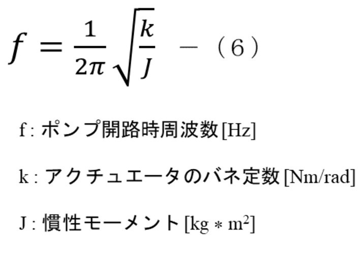
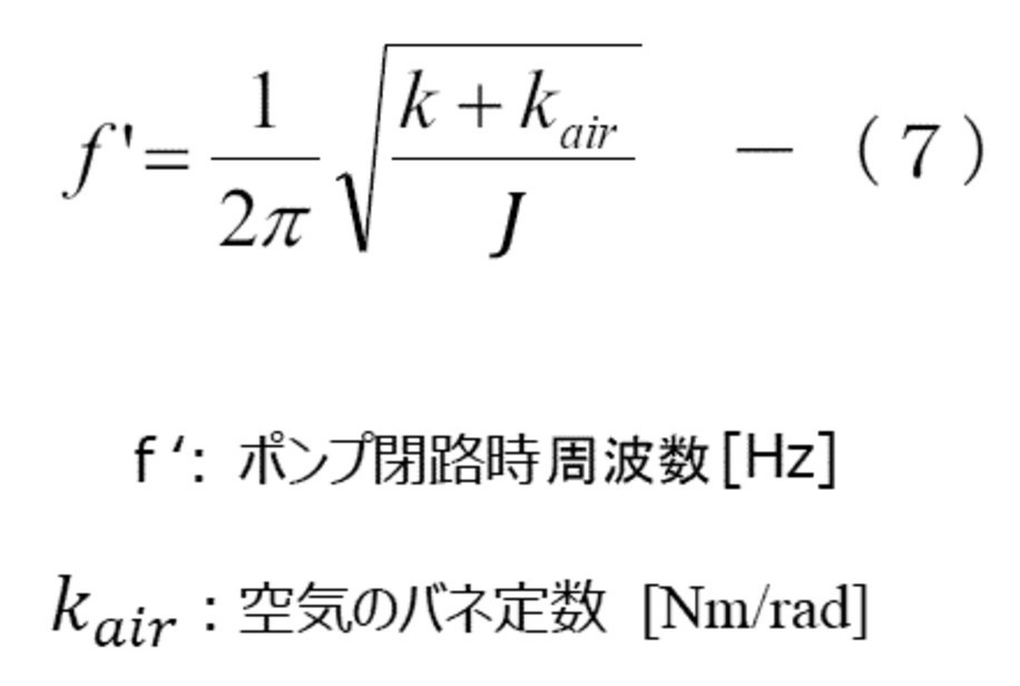
このようなことを踏まえて、ポンプ制御システム100は、図14に示すタンク部内の空気の圧力とタンク部からの空気の流量の周波数特性を有する。図14は、本実施の形態の共振タイプのポンプを用いた際のポンプ開路時とポンプ閉路時のタンク部内の空気の圧力の周波数特性を示す図である。図14に示すように、共振タイプのポンプの場合、各駆動周波数における閉路時のタンク部内の空気の圧力G1と、開路時のポンプからタンク部への空気の流量を表す、タンク部内への空気の圧力G2(以下、G2はポンプからタンク部内への空気の流量を表すので、流量G2という)のそれぞれの最大値は、それぞれ異なる共振周波数帯(共振点H1、H2近傍)での駆動により実現される。例えば、駆動周波数H1(第1駆動周波数H1)で共振駆動する共振タイプのポンプの場合、開路時において、駆動周波数H1(第1駆動周波数H1)で駆動させれば、流量G2は大きくなる(図では最大値)。しかしながら、閉路時では、空気がバネとして振動体30に作用するため、ポンプの振動体30の共振点がシフトしてしまい(図14では共振点がH2にシフト)、圧力G1は上がりにくくなる。一方、共振点がシフトすることを踏まえ、駆動周波数H1よりも高い周波数である駆動周波数H2付近の周波数(第2駆動周波数H2)で共振駆動させれば、圧力G1は大きくなるものの、流量G2の出にくい共振周波数での使用となる。このように、一例としての血圧計のように、タンク部120内において所望の圧力が必要となされる製品においては、単一の周波数で共振駆動した場合、流量・圧力のいずれかにおいて不利な周波数で駆動しなくてはならない。
Based on this, the pump control system 100 has frequency characteristics of the air pressure in the tank portion and the flow rate of the air from the tank portion shown in FIG. FIG. 14 is a diagram showing the frequency characteristics of the pressure of the air in the tank portion when the pump is open and when the pump is closed when the resonance type pump of the present embodiment is used. As shown in FIG. 14, in the case of a resonance type pump, the air pressure G1 in the tank portion at each drive frequency and the air flow rate from the pump to the tank portion at the time of opening the circuit are shown. The maximum value of each pressure G2 (hereinafter, G2 represents the flow rate of air from the pump to the inside of the tank is referred to as the flow rate G2) is realized by driving in different resonance frequency bands (near resonance points H1 and H2). Will be done. For example, in the case of a resonance type pump that is resonantly driven at the drive frequency H1 (first drive frequency H1), the flow rate G2 increases if the pump is driven at the drive frequency H1 (first drive frequency H1) at the time of opening the circuit (FIG. Then the maximum value). However, when the circuit is closed, air acts on the vibrating body 30 as a spring, so that the resonance point of the vibrating body 30 of the pump shifts (the resonance point shifts to H2 in FIG. 14), and the pressure G1 is difficult to increase. On the other hand, based on the fact that the resonance point shifts, if resonance drive is performed at a frequency near the drive frequency H2 (second drive frequency H2), which is a frequency higher than the drive frequency H1, the pressure G1 increases, but the flow rate G2 It will be used at a resonance frequency that is difficult to generate. In this way, in a product that requires a desired pressure in the tank unit 120, such as a blood pressure monitor as an example, when resonance driving is performed at a single frequency, a frequency that is disadvantageous in either flow rate or pressure. Must be driven by.
この特性を利用するため、本実施形態のポンプ制御システム100では、マイコン部140(制御部)は、所定の容量のタンク部120内の圧力を所定の圧力値になるまで増加させる場合、駆動周波数を変更する。具体的には、マイコン部140は、ポンプ1からタンク部120への空気の流量G2を最大化する第1駆動周波数H1と、タンク部120内の空気の圧力G1を最大化する第2駆動周波数H2と、の間で、駆動周波数を切り替えることで駆動周波数を変更する。
In order to utilize this characteristic, in the pump control system 100 of the present embodiment, when the microcomputer unit 140 (control unit) increases the pressure in the tank unit 120 having a predetermined capacity to a predetermined pressure value, the drive frequency To change. Specifically, the microcomputer unit 140 has a first drive frequency H1 that maximizes the air flow rate G2 from the pump 1 to the tank unit 120, and a second drive frequency that maximizes the air pressure G1 in the tank unit 120. The drive frequency is changed by switching the drive frequency between H2 and H2.
図15は、本発明に係る実施の形態のポンプ制御システム100における周波数制御の一例を示す図である。
FIG. 15 is a diagram showing an example of frequency control in the pump control system 100 according to the embodiment of the present invention.
ポンプ制御システム100では、マイコン部140は、タンク部120内に空気(流体)を供給して、タンク部120内の空気の圧力が、所望の圧力になるまで、タンク部120内の空気の圧力を増加させる。
In the pump control system 100, the microcomputer unit 140 supplies air (fluid) into the tank unit 120, and the pressure of the air in the tank unit 120 until the pressure of the air in the tank unit 120 reaches a desired pressure. To increase.
所望の圧力(値)は、本実施形態のポンプ制御装置及びポンプ制御システム100の適用対象によって適宜異なる。ポンプ制御システム100(ポンプ制御装置)を、例えば、血圧計に適用する場合とすると、高血圧治療ガイドライン(JSH2004)では高血圧が、18kPa(135mmHg)以上であるとされ、また、非観血式機械血圧計のJIS規格(T115)では40kPaを超えてはならないとされており、これらに基づいて設定される。所望の圧力値を40kPaとし、18kPa~40kPaまで変更できるものとしてもよい。以下、図15を参照して、タンク容量を一定の容量(例えば、500cc)として、ポンプ制御システム100によりタンク部120の圧力を40kPaまで増加させる場合について詳述する。
The desired pressure (value) appropriately differs depending on the application target of the pump control device and the pump control system 100 of the present embodiment. When the pump control system 100 (pump control device) is applied to a sphygmomanometer, for example, the hypertension treatment guideline (JSH2004) states that the hypertension is 18 kPa (135 mmHg) or more, and the non-invasive mechanical blood pressure. According to the JIS standard (T115) of the total, it should not exceed 40 kPa, and it is set based on these. The desired pressure value may be set to 40 kPa and may be changed from 18 kPa to 40 kPa. Hereinafter, with reference to FIG. 15, a case where the tank capacity is set to a constant capacity (for example, 500 cc) and the pressure of the tank unit 120 is increased to 40 kPa by the pump control system 100 will be described in detail.
この場合、マイコン部140は、圧力0からの増加が早い周波数、つまり、圧力が0から立ち上がる増加度が高い周波数の駆動信号をコイルコイル50a、50bに供給する。より具体的には、第1駆動周波数H1、第2駆動周波数H2のうちの低い周波数(図14と同様にH1で示す)、すなわち、第1駆動周波数H1の駆動信号を、コイル50a、50bに入力して励磁する。
In this case, the microcomputer unit 140 supplies the coil coils 50a and 50b with a drive signal having a frequency in which the pressure increases rapidly from 0, that is, a frequency in which the pressure rises from 0 and has a high degree of increase. More specifically, the lower frequency of the first drive frequency H1 and the second drive frequency H2 (shown by H1 as in FIG. 14), that is, the drive signal of the first drive frequency H1 is transmitted to the coils 50a and 50b. Input and excite.
図15は、第1駆動周波数H1での駆動と、第2駆動周波数H2(>H1)での駆動(図14のH2で示す周波数と同様にH2で示す)よる圧力と、圧力増加時間の関係を示している。そして、マイコン部140は、所定の切り替えタイミングで、第1駆動周波数H1の処理から第2駆動周波数H2の処理に切り替える。この切り替えタイミングは、タンク部120内の空気の圧力状態に基づいて変更される。タンク部120内の空気の圧力値の増加を示す傾きが緩やかになるタイミングは、図15では、「周波数切替」で示されている。この緩やかになったタイミングで、駆動周波数を、第1駆動周波数H1から第2駆動周波数H2に変更する。これにより、立ち上がり時(ポンプ1の起動時)においては、タンク部120内の空気の圧力の増加が早い第1駆動周波数H1の駆動信号でポンプ1を駆動し、第1駆動周波数H1の駆動信号では、タンク部120内の空気の圧力の増加を示す傾きが緩やかになるタイミング(図15中における「周波数切替」)で、駆動周波数を、第1駆動周波数H1から第2駆動周波数H2に変更する。このように、第1駆動周波数H1から第2駆動周波数H2に駆動周波数にシフトすることによる特性を、図15中においてK1で示す。
FIG. 15 shows the relationship between the drive at the first drive frequency H1 and the pressure due to the drive at the second drive frequency H2 (> H1) (shown by H2 as well as the frequency shown by H2 in FIG. 14) and the pressure increase time. Is shown. Then, the microcomputer unit 140 switches from the processing of the first driving frequency H1 to the processing of the second driving frequency H2 at a predetermined switching timing. This switching timing is changed based on the pressure state of the air in the tank portion 120. In FIG. 15, the timing at which the inclination indicating the increase in the pressure value of the air in the tank portion 120 becomes gentle is indicated by “frequency switching”. At this gradual timing, the drive frequency is changed from the first drive frequency H1 to the second drive frequency H2. As a result, at the time of rising (when the pump 1 is started), the pump 1 is driven by the drive signal of the first drive frequency H1 in which the pressure of the air in the tank portion 120 increases quickly, and the drive signal of the first drive frequency H1 is driven. Then, the drive frequency is changed from the first drive frequency H1 to the second drive frequency H2 at the timing when the inclination indicating the increase in the pressure of the air in the tank portion 120 becomes gentle (“frequency switching” in FIG. 15). .. In this way, the characteristic of shifting from the first drive frequency H1 to the second drive frequency H2 to the drive frequency is shown by K1 in FIG.
具体的には、異なる周波数(例えば第1駆動周波数H1、第2駆動周波数H2)を比較して、0から立ち上がり、駆動周波数を切り替えるタイミングでの圧力値、すなわち、過程値(10kPa程度)までの圧力増加時間が短い第1駆動周波数で、コイル50a、50bを励磁し、振動体30を共振駆動する。第1駆動周波数H1での共振駆動では、10kPa程度まではタンク部120内の空気の圧力の増加時間は短い。しかしながら、第1駆動周波数H1での共振駆動を続けた場合、タンク部120内の圧力は、所望の圧力値(例えば、40kPa)まで、増加しない。
Specifically, different frequencies (for example, the first drive frequency H1 and the second drive frequency H2) are compared, and the pressure value at the timing of rising from 0 and switching the drive frequency, that is, up to the process value (about 10 kPa). The coils 50a and 50b are excited to resonately drive the vibrating body 30 at the first driving frequency in which the pressure increase time is short. In the resonance drive at the first drive frequency H1, the increase time of the air pressure in the tank portion 120 is short up to about 10 kPa. However, when the resonance drive at the first drive frequency H1 is continued, the pressure in the tank portion 120 does not increase to a desired pressure value (for example, 40 kPa).
また、第1駆動周波数H1よりも高い第2駆動周波数H2で共振駆動した場合、タンク部120内の空気の圧力を、所望の高い圧力(例えば、40kPa)は超えさせることができるものの、第1駆動周波数H1によって共振駆動した場合に比べて、タンク部120内の空気の0から過程値(10kPa程度)までの圧力増加時間が長い。よって、本実施形態では、第1駆動周波数H1の駆動信号でポンプ1の共振駆動を開始し、所定の切り替えタイミング、例えば、10KPaで、駆動信号の駆動周波数を、第2駆動周波数H2に変更する。これにより、図15に示す特性K1で、ポンプ1の駆動することができる。
Further, when resonance driving is performed at a second driving frequency H2 higher than the first driving frequency H1, the pressure of the air in the tank portion 120 can be exceeded by a desired high pressure (for example, 40 kPa), but the first The pressure increase time from 0 to the process value (about 10 kPa) of the air in the tank portion 120 is longer than that in the case of resonance driving by the drive frequency H1. Therefore, in the present embodiment, the resonance drive of the pump 1 is started by the drive signal of the first drive frequency H1, and the drive frequency of the drive signal is changed to the second drive frequency H2 at a predetermined switching timing, for example, 10 KPa. .. As a result, the pump 1 can be driven by the characteristic K1 shown in FIG.
これにより、単一の周波数(第2駆動周波数H2)での共振駆動と比較して、より早い時間で圧力を増加させることが可能となる。具体的には、図15中において、第2駆動周波数H2でのみ共振駆動した場合の特性曲線(図15中において、点線で示されているグラフ)よりも、特性K1の特性曲線の方が、所望の高い圧力(例えば、40kPa)をより短い時間で達成することができる。
This makes it possible to increase the pressure in a faster time as compared with the resonance drive at a single frequency (second drive frequency H2). Specifically, in FIG. 15, the characteristic curve of the characteristic K1 is more than the characteristic curve in the case of resonance driving only at the second drive frequency H2 (the graph shown by the dotted line in FIG. 15). The desired high pressure (eg 40 kPa) can be achieved in a shorter amount of time.
図16は、本発明の実施の形態に係るポンプの制御フローの一例を示す図である。図16に示すように、まず、ステップS11では、ポンプ制御システム100の駆動信号の駆動周波数を、駆動周波数1(第1駆動周波数H1)を設定する。ステップS12では、マイコン部140は、圧力測定部130によりタンク部120内の圧力を計測して、取得部146で、タンク部120内の空気の圧力値として取得する。ステップS13では、マイコン部140は、取得した空気の圧力値が、切替圧力値(過程値)であるか否かを判定し、取得した空気の圧力値が、切替圧力値になるまで判定を繰り返す。すなわち、ステップS13では、ポンプ1からタンク部120への空気(流体)の流量G2を最大化する第1駆動周波数H1と、タンク部120内の空気(流体)の圧力G1を最大化する第2駆動周波数H2と、の間で、コイル50a、50bに供給する電流の駆動周波数を切り替える。ステップS13において、圧力値が、切替圧力値に到達していれば、ステップS14に移行して、コイル50a、50bに供給する電流の駆動周波数を、駆動周波数2(第2駆動周波数H2)に設定する。
FIG. 16 is a diagram showing an example of a control flow of the pump according to the embodiment of the present invention. As shown in FIG. 16, first, in step S11, the drive frequency of the drive signal of the pump control system 100 is set to the drive frequency 1 (first drive frequency H1). In step S12, the microcomputer unit 140 measures the pressure in the tank unit 120 by the pressure measuring unit 130, and acquires it as the pressure value of the air in the tank unit 120 by the acquisition unit 146. In step S13, the microcomputer unit 140 determines whether or not the acquired air pressure value is a switching pressure value (process value), and repeats the determination until the acquired air pressure value reaches the switching pressure value. .. That is, in step S13, the first drive frequency H1 for maximizing the flow rate G2 of air (fluid) from the pump 1 to the tank portion 120 and the second driving frequency H1 for maximizing the pressure G1 of the air (fluid) in the tank portion 120 are maximized. The drive frequency of the current supplied to the coils 50a and 50b is switched between the drive frequency H2 and the drive frequency H2. If the pressure value reaches the switching pressure value in step S13, the process proceeds to step S14, and the drive frequency of the current supplied to the coils 50a and 50b is set to the drive frequency 2 (second drive frequency H2). do.
次いで、マイコン部140は、タンク部120内の空気の圧力を計測し(ステップS15)、必要な圧力であるかどうか、つまり、所望の圧力値まで達したか否か(ステップS16)を判定し、所望の圧力値になるまでこれを繰り返す。
Next, the microcomputer unit 140 measures the pressure of the air in the tank unit 120 (step S15), and determines whether or not the pressure is required, that is, whether or not the desired pressure value has been reached (step S16). , Repeat this until the desired pressure value is reached.
本実施形態は、例えば、単一周波数毎の駆動を用いた周波数応答計測(設定した各駆動周波数で駆動し、その駆動による圧力が最大圧力値である場合に、現在の駆動周波数が、必要駆動周波数であるかを判定するまでの一連の計測処理)と異なる。つまり、本実施形態によれば、周波数応答計測と異なり、設定した各駆動周波数で最大圧力を出するように制御することがなく、制御時間が増加することがない。本実施形態によれば、ポンプの小型化が可能であるとともに、より好適なポンプ圧力、流量を確保でき、安定して駆動できる。特に、共振タイプの振動アクチュエータを用いたポンプにおいて、単一周波数での駆動に比べて早い時間で、タンク部120内の空気の圧力を増加させることができる。
In this embodiment, for example, frequency response measurement using driving for each single frequency (when driving at each set driving frequency and the pressure due to the driving is the maximum pressure value, the current driving frequency is required driving. It is different from a series of measurement processes until it is determined whether it is a frequency). That is, according to the present embodiment, unlike the frequency response measurement, the control is not performed so as to output the maximum pressure at each set drive frequency, and the control time does not increase. According to this embodiment, the pump can be miniaturized, more suitable pump pressure and flow rate can be secured, and stable driving can be performed. In particular, in a pump using a resonance type vibration actuator, the pressure of air in the tank portion 120 can be increased in a shorter time than driving at a single frequency.
(第2実施形態)
図17は、本発明の第2実施形態に係るポンプの概略構成を示すブロック図である。図17に示すポンプ制御システム100Aは、ポンプ制御システム100と比較して、圧力検出部130(図1参照)に替えてタイマー160を用いる。 (Second Embodiment)
FIG. 17 is a block diagram showing a schematic configuration of a pump according to a second embodiment of the present invention. Thepump control system 100A shown in FIG. 17 uses a timer 160 instead of the pressure detection unit 130 (see FIG. 1) as compared with the pump control system 100.
図17は、本発明の第2実施形態に係るポンプの概略構成を示すブロック図である。図17に示すポンプ制御システム100Aは、ポンプ制御システム100と比較して、圧力検出部130(図1参照)に替えてタイマー160を用いる。 (Second Embodiment)
FIG. 17 is a block diagram showing a schematic configuration of a pump according to a second embodiment of the present invention. The
第2実施形態に係るポンプ制御システム100Aの基本的な構成は、第1実施形態のポンプ制御システム100の基本的な構成と同様であるので、異なる構成のみ説明し、同様の構成については、同符号同名称を付して説明は省略する。
Since the basic configuration of the pump control system 100A according to the second embodiment is the same as the basic configuration of the pump control system 100 of the first embodiment, only different configurations will be described, and the same configuration will be the same. The same name is given and the description is omitted.
ポンプ制御システム100Aは、ポンプ1と、タンク部120と、マイコン部140Aと、タイマー160とを有する。
The pump control system 100A includes a pump 1, a tank unit 120, a microcomputer unit 140A, and a timer 160.
タイマー160は、タンク部120内の空気(流体)の圧力を増加させる際に、振動体30の駆動時間を計測し、振動体30の駆動時間を得る。取得部146は、振動体30の駆動時間を取得する。取得部146がタイマー160から振動体30の駆動時間を取得すると、振動体30の駆動時間から、圧力値情報が取得される。この圧力値情報は、本実施形態では、予め設定された振動体30の駆動時間とこの駆動時間駆動により増加するタンク部120内の空気の圧力との関係を示すテーブルであり、記憶部142に格納される。このテーブルは、例えば、タンク部120内の空気の圧力を増加させる過程で、コイル50a、50bに供給する電流の駆動周波数を、第1駆動周波数H1から第2駆動周波数H2に切り替えるタイミングを示すタイミングテーブルである。
The timer 160 measures the driving time of the vibrating body 30 when increasing the pressure of the air (fluid) in the tank portion 120, and obtains the driving time of the vibrating body 30. The acquisition unit 146 acquires the driving time of the vibrating body 30. When the acquisition unit 146 acquires the driving time of the vibrating body 30 from the timer 160, the pressure value information is acquired from the driving time of the vibrating body 30. In the present embodiment, this pressure value information is a table showing the relationship between the preset drive time of the vibrating body 30 and the pressure of air in the tank unit 120 increased by the drive time drive, and is stored in the storage unit 142. Stored. This table shows, for example, the timing of switching the drive frequency of the current supplied to the coils 50a and 50b from the first drive frequency H1 to the second drive frequency H2 in the process of increasing the pressure of the air in the tank portion 120. It is a table.
マイコン部140Aは、記憶部142内のテーブルを用いて各部を動作し、特に、取得部146で圧力値情報として取得されたテーブルに基づいて、コイル50a、50bへ供給する電流の駆動周波数を制御する。このように、ポンプ制御システム100Aでは、タンク部120の圧力を測定することなく、マイコン部140Aは、タンク部120内の空気の圧力が増加している圧力増加時間、すなわち、振動体30の駆動時間をタイマー160で取得し、圧力に対応する値を示す圧力値情報を取得部146で取得する。マイコン部140Aは、この取得した情報に基づいて、コイル50a、50bへ供給する電流の駆動周波数を制御する。
The microcomputer unit 140A operates each unit using the table in the storage unit 142, and in particular, controls the drive frequency of the current supplied to the coils 50a and 50b based on the table acquired as the pressure value information by the acquisition unit 146. do. As described above, in the pump control system 100A, the microcomputer unit 140A does not measure the pressure of the tank unit 120, but the microcomputer unit 140A drives the vibrating body 30 during the pressure increase time during which the pressure of the air in the tank unit 120 is increasing. The time is acquired by the timer 160, and the pressure value information indicating the value corresponding to the pressure is acquired by the acquisition unit 146. The microcomputer unit 140A controls the drive frequency of the current supplied to the coils 50a and 50b based on the acquired information.
これにより、マイコン部140Aは、コイル50a、50bに供給する電流の駆動周波数を制御する際の周波数切替時間(タイミング)を設定することができ、マイコン部140と同様の動作を行うことができる。マイコン部140Aの動作の一例を、図15を参照して説明する。図15では、第1駆動周波数H1で駆動すると、約5秒経過した段階(図15では「周波数切替」で示す位置)で圧力が増加しにくくなっている。このような周波数切替位置を示すタイミングテーブルが、圧力値情報として、記憶部142に格納されてもよい。
As a result, the microcomputer unit 140A can set the frequency switching time (timing) when controlling the drive frequency of the current supplied to the coils 50a and 50b, and can perform the same operation as the microcomputer unit 140. An example of the operation of the microcomputer unit 140A will be described with reference to FIG. In FIG. 15, when driven at the first drive frequency H1, the pressure is less likely to increase at the stage where about 5 seconds have elapsed (the position indicated by “frequency switching” in FIG. 15). A timing table showing such a frequency switching position may be stored in the storage unit 142 as pressure value information.
マイコン部140Aは、記憶部142に格納された圧力値情報、つまり、周波数切替位置を示すタイミングテーブルに基づいて、圧力増加開始から5秒後に、コイル50a、50bに供給する電流の駆動周波数を、第1駆動周波数H1から第2駆動周波数H2に切り替える制御を行う。これにより、マイコン部140Aは、圧力検出部130で検出した圧力値を用いた場合と同様に、第1駆動周波数H1から第2駆動周波数H2にシフトした特性K1を得られるよう、コイル50a、50bに供給する電流の駆動周波数を制御できる。
Based on the pressure value information stored in the storage unit 142, that is, the timing table indicating the frequency switching position, the microcomputer unit 140A sets the drive frequency of the current supplied to the coils 50a and 50b 5 seconds after the start of the pressure increase. Control is performed to switch from the first drive frequency H1 to the second drive frequency H2. As a result, the microcomputer unit 140A can obtain the characteristics K1 shifted from the first drive frequency H1 to the second drive frequency H2, as in the case of using the pressure value detected by the pressure detection unit 130, so that the coils 50a and 50b can be obtained. The drive frequency of the current supplied to the can be controlled.
<切換パターン1>
図18、図19はタンク容量が異なる場合のコイル50a、50bに供給する電流の駆動周波数制御のパターンを示す図である。図20は、第1実施形態のポンプを用いて、圧力値で駆動周波数を切り替える場合のテーブルを示す。図21A、図21Bは、第2実施形態のポンプを用いて、時間で駆動周波数を切り替える場合のテーブルを示す。なお、各図において、対応する圧力、流量が異なる初期駆動周波数として150Hz、250Hz、270Hzとしているが、これは一例であり、異なる複数の周波数であれば、高低は限定されない。 <Switching pattern 1>
18 and 19 are diagrams showing a pattern of driving frequency control of the current supplied to the coils 50a and 50b when the tank capacities are different. FIG. 20 shows a table in which the drive frequency is switched by the pressure value using the pump of the first embodiment. 21A and 21B show a table in the case of switching the drive frequency with time using the pump of the second embodiment. In each figure, the initial drive frequencies having different pressures and flow rates are 150 Hz, 250 Hz, and 270 Hz, but this is an example, and the high and low frequencies are not limited as long as they are a plurality of different frequencies.
図18、図19はタンク容量が異なる場合のコイル50a、50bに供給する電流の駆動周波数制御のパターンを示す図である。図20は、第1実施形態のポンプを用いて、圧力値で駆動周波数を切り替える場合のテーブルを示す。図21A、図21Bは、第2実施形態のポンプを用いて、時間で駆動周波数を切り替える場合のテーブルを示す。なお、各図において、対応する圧力、流量が異なる初期駆動周波数として150Hz、250Hz、270Hzとしているが、これは一例であり、異なる複数の周波数であれば、高低は限定されない。 <
18 and 19 are diagrams showing a pattern of driving frequency control of the current supplied to the
図18及び図19に示す特性K2、K3は、ポンプ開路時とポンプ閉路時で特性が異なる共振タイプのアクチュエータの特性(図14参照)において、「流量の出やすい周波数帯域(領域)」の周波数を用いたときの特性である。
The characteristics K2 and K3 shown in FIGS. 18 and 19 are frequencies in the "frequency band (region) in which the flow rate is likely to occur" in the characteristics of the resonance type actuator (see FIG. 14), which have different characteristics when the pump is open and when the pump is closed. It is a characteristic when using.
第1実施形態のポンプ制御システム100は、圧力測定部130により計測されるタンク部120内の圧力値に基づいて、図20のテーブルを用いて、図18及び図19に示す駆動周波数制御を行う。図18及び図19では、駆動信号の駆動周波数を、周波数シフトして特性K2、K3となるように制御する際に、2回、コイル50a、50bに供給する電流の駆動周波数を変更し、タンク部120内の圧力の増加時間の短縮化が図られている。2回の駆動周波数の変更は、いずれも、タンク部120内の空気の圧力の増加過程で、空気の流量G2を最大化する駆動周波数と、空気の圧力G1を最大化する駆動周波数と、の間で、コイル50a、50bに供給する電流の駆動周波数を切り替えることで行われている。
The pump control system 100 of the first embodiment performs the drive frequency control shown in FIGS. 18 and 19 using the table of FIG. 20 based on the pressure value in the tank unit 120 measured by the pressure measuring unit 130. .. In FIGS. 18 and 19, when the drive frequency of the drive signal is frequency-shifted to obtain the characteristics K2 and K3, the drive frequency of the current supplied to the coils 50a and 50b is changed twice to obtain the tank. The time for increasing the pressure in the unit 120 is shortened. The two changes in the drive frequency are the drive frequency that maximizes the air flow rate G2 and the drive frequency that maximizes the air pressure G1 in the process of increasing the air pressure in the tank portion 120. This is done by switching the drive frequency of the current supplied to the coils 50a and 50b.
図20では、初期駆動周波数の例として、3つの異なる周波数[Hz]と、それらの周波数に切り替える際のタンク部120内の流体の圧力(「目標圧力」)とを対応させている。これにより、ポンプ制御システム100は、タンク容量に関わらず、タンク部120内の流体の圧力変化に対応して、タンク部120内の空気を、単一の周波数で駆動させるよりも早く(図18及び図19に、増加時間の短縮を示す矢印参照)、効果的に増加させることができる。
In FIG. 20, as an example of the initial drive frequency, three different frequencies [Hz] are associated with the pressure of the fluid in the tank portion 120 (“target pressure”) when switching to those frequencies. As a result, the pump control system 100 responds to changes in the pressure of the fluid in the tank section 120 regardless of the tank capacity, and is faster than driving the air in the tank section 120 at a single frequency (FIG. 18). And in FIG. 19, see the arrow showing the reduction of the increase time), which can be effectively increased.
第2実施形態のポンプ制御システム100Aのマイコン部140Aは、図21Aに示すテーブルを用いて、図18に示す特性K2となるような制御を行い、図21Bのテーブルを用いて図19に示す特性K3となるような制御を行う。図21A、図21Bの各テーブルは、それぞれ異なる複数の初期駆動周波数と、これら初期駆動周波数のそれぞれにより駆動する時間、及び駆動時間に対応した目標圧力とが関連付けられたテーブルを有し、記憶部142に格納される。これにより、ポンプ制御システム100Aは、タンク容量に応じたテーブルを用いて、タンク部120内の流体の圧力変化に対応して、単一の周波数駆動よりも早く、タンク部120内の空気を効果的に増加させることができる。
The microcomputer unit 140A of the pump control system 100A of the second embodiment uses the table shown in FIG. 21A to perform control so as to have the characteristic K2 shown in FIG. 18, and uses the table of FIG. 21B to perform the characteristics shown in FIG. Control is performed so as to be K3. Each table of FIGS. 21A and 21B has a plurality of different initial drive frequencies, a time driven by each of these initial drive frequencies, and a table in which a target pressure corresponding to the drive time is associated with the storage unit. It is stored in 142. As a result, the pump control system 100A uses a table according to the tank capacity to respond to the pressure change of the fluid in the tank unit 120 and to effect the air in the tank unit 120 faster than a single frequency drive. Can be increased.
<切換パターン2>
図22は、本第1実施形態、2による周波数制御により、タンク内の空気を緩やかに増加させたパターンを示す図であり、図23は、第1実施形態のポンプを用いて、圧力値により図22で示す駆動周波数を切り替えて、特性K4となるように制御する場合のテーブルを示す。また、図24は、第2実施形態のポンプを用いて、時間により図22で示す駆動周波数を切り替えて、特性K4となるように制御する場合のテーブルを示す。なお、各図において初期駆動周波数として300Hz、280Hz、270Hzとしているが、これは一例であり、異なる複数の周波数であれば、数値の高低は限定されない。 <Switching pattern 2>
FIG. 22 is a diagram showing a pattern in which the air in the tank is gradually increased by frequency control according to the first embodiment and 2, and FIG. 23 is a diagram showing a pattern in which the air in the tank is gradually increased by the pressure value using the pump of the first embodiment. A table is shown in the case where the drive frequency shown in FIG. 22 is switched and controlled so as to have the characteristic K4. Further, FIG. 24 shows a table in the case where the pump of the second embodiment is used to switch the drive frequency shown in FIG. 22 with time to control the characteristic K4. In each figure, the initial drive frequency is set to 300 Hz, 280 Hz, and 270 Hz, but this is an example, and the numerical value is not limited as long as it is a plurality of different frequencies.
図22は、本第1実施形態、2による周波数制御により、タンク内の空気を緩やかに増加させたパターンを示す図であり、図23は、第1実施形態のポンプを用いて、圧力値により図22で示す駆動周波数を切り替えて、特性K4となるように制御する場合のテーブルを示す。また、図24は、第2実施形態のポンプを用いて、時間により図22で示す駆動周波数を切り替えて、特性K4となるように制御する場合のテーブルを示す。なお、各図において初期駆動周波数として300Hz、280Hz、270Hzとしているが、これは一例であり、異なる複数の周波数であれば、数値の高低は限定されない。 <
FIG. 22 is a diagram showing a pattern in which the air in the tank is gradually increased by frequency control according to the first embodiment and 2, and FIG. 23 is a diagram showing a pattern in which the air in the tank is gradually increased by the pressure value using the pump of the first embodiment. A table is shown in the case where the drive frequency shown in FIG. 22 is switched and controlled so as to have the characteristic K4. Further, FIG. 24 shows a table in the case where the pump of the second embodiment is used to switch the drive frequency shown in FIG. 22 with time to control the characteristic K4. In each figure, the initial drive frequency is set to 300 Hz, 280 Hz, and 270 Hz, but this is an example, and the numerical value is not limited as long as it is a plurality of different frequencies.
図22に示す周波数制御は、図14で示す共振タイプのアクチュエータの特性において、第2駆動周波数H2よりも高い周波数領域である「流量の出難い周波数帯域(領域)」の周波数を用いている。このように、コイル50a、50bに供給する電流の駆動周波数を制御するポンプ制御システムは、緩やかに空気圧を増加させたい場合等、圧力増加時間を延長する場合に用いられる。例えば、ポンプは、乳幼児の血管検査、被検者へのベルトの締め付け等の際に、緩やかに空気を送る必要がある場合で使用される。
In the frequency control shown in FIG. 22, in the characteristics of the resonance type actuator shown in FIG. 14, the frequency in the "frequency band (region) in which the flow rate is difficult to output", which is a frequency region higher than the second drive frequency H2, is used. In this way, the pump control system that controls the drive frequency of the current supplied to the coils 50a and 50b is used when the pressure increase time is extended, such as when the air pressure is to be gradually increased. For example, a pump is used when it is necessary to send air gently when performing a blood vessel examination of an infant, tightening a belt to a subject, or the like.
<第3実施形態>
図25は、本発明の第3実施形態に係るポンプ制御システムを模式的に示す図である。図25に示すポンプ制御システムは、例えば、血圧装置10Dである。血圧装置10Dは、タンク部120に相当するカフ102と、カフに空気を送る管部5と、ポンプ駆動ユニット101と、圧力測定部13Dとを有する。 <Third Embodiment>
FIG. 25 is a diagram schematically showing a pump control system according to a third embodiment of the present invention. The pump control system shown in FIG. 25 is, for example, ablood pressure device 10D. The blood pressure device 10D includes a cuff 102 corresponding to a tank unit 120, a pipe unit 5 for sending air to the cuff, a pump drive unit 101, and a pressure measuring unit 13D.
図25は、本発明の第3実施形態に係るポンプ制御システムを模式的に示す図である。図25に示すポンプ制御システムは、例えば、血圧装置10Dである。血圧装置10Dは、タンク部120に相当するカフ102と、カフに空気を送る管部5と、ポンプ駆動ユニット101と、圧力測定部13Dとを有する。 <Third Embodiment>
FIG. 25 is a diagram schematically showing a pump control system according to a third embodiment of the present invention. The pump control system shown in FIG. 25 is, for example, a
駆動ユニット101は、図1に示すポンプ1である共振ポンプ1Dと、マイコン部としての制御部140とを有する。
The drive unit 101 includes a resonance pump 1D, which is the pump 1 shown in FIG. 1, and a control unit 140 as a microcomputer unit.
マイコン部である制御部140は、共振ポンプ1D、圧力測定部13Dに接続されており、共振ポンプ1Dに対して駆動信号を供給する。
The control unit 140, which is a microcomputer unit, is connected to the resonance pump 1D and the pressure measurement unit 13D, and supplies a drive signal to the resonance pump 1D.
共振ポンプ1Dは、マイコン部140からの駆動信号に従って駆動する。具体的には、共振ポンプ1Dの吐出部86に管部5を接続して共振ポンプ1Dにおいて、振動体30が振動し、ポンプ部を駆動し、血圧計検査等カフに好適に空気を供給できる。ポンプ制御システムの構成により、小型化が可能であるとともに、より好適なポンプ圧力、流量を確保でき、安定して駆動できるともに、カフに対して、短い時間でカフ内の圧力を所望の圧力値まで増加させることができる。
The resonance pump 1D is driven according to the drive signal from the microcomputer unit 140. Specifically, the pipe portion 5 is connected to the discharge portion 86 of the resonance pump 1D, and in the resonance pump 1D, the vibrating body 30 vibrates to drive the pump portion, and air can be suitably supplied to the cuff such as a sphygmomanometer test. .. Due to the configuration of the pump control system, it is possible to reduce the size, secure more suitable pump pressure and flow rate, and drive stably, and at the same time, the pressure inside the cuff can be adjusted to the desired pressure value in a short time. Can be increased up to.
以上、本発明の実施の形態について説明した。なお、以上の説明は本発明の好適な実施の形態の例証であり、本発明の範囲はこれに限定されない。つまり、上記装置の構成や各部分の形状についての説明は一例であり、本発明の範囲においてこれらの例に対する様々な変更や追加が可能であることは明らかである。
The embodiment of the present invention has been described above. The above description is an example of a preferred embodiment of the present invention, and the scope of the present invention is not limited thereto. That is, the description of the configuration of the device and the shape of each part is an example, and it is clear that various changes and additions to these examples are possible within the scope of the present invention.
本発明に係るポンプは、小型化が可能であるとともに、より好適なポンプ圧力、流量を確保でき、安定して駆動できる効果を有する。例えば、本発明に係るポンプは、薄型化高出力化が望まれるウェアラブル装置として有用である。したがって、本発明は産業上の利用可能性を有する。
The pump according to the present invention can be miniaturized, can secure a more suitable pump pressure and flow rate, and has an effect of being able to be driven stably. For example, the pump according to the present invention is useful as a wearable device for which thinning and high output are desired. Therefore, the present invention has industrial applicability.
Claims (7)
- コイルへの電流供給による電磁駆動により振動体を振動させる振動アクチュエータと、
前記振動体の振動により変位する可動壁を有し、前記可動壁の変位により、内部の容積が変更されて流体が前記内部に吸入されまたは前記内部から吐出される密閉室と、
前記密閉室から吐出される前記流体を溜めて前記流体の圧力を増加させるタンクと前記密閉室とを流体連通させる吐出部と、
を有するポンプを制御するためのポンプ制御装置であって、
前記タンク内の前記流体の圧力の値または前記圧力に対応する値を示す圧力値情報を取得する取得部と、
取得された圧力値情報に基づいて、前記コイルへ供給する電流の駆動周波数を制御する制御部と、を有するポンプ制御装置。 A vibrating actuator that vibrates the vibrating body by electromagnetic drive by supplying current to the coil,
A closed chamber having a movable wall that is displaced by the vibration of the vibrating body, and a fluid is sucked into or discharged from the inside by changing the internal volume due to the displacement of the movable wall.
A discharge unit for communicating the fluid between the tank for collecting the fluid discharged from the closed chamber and increasing the pressure of the fluid and the closed chamber.
It is a pump control device for controlling a pump having
An acquisition unit that acquires pressure value information indicating a pressure value of the fluid in the tank or a value corresponding to the pressure, and an acquisition unit.
A pump control device including a control unit that controls a drive frequency of a current supplied to the coil based on the acquired pressure value information. - 前記制御部は、前記電流が、前記タンク内の前記流体の圧力に応じて異なる前記振動体の共振周波数で、前記コイルに供給されるように、前記駆動周波数を制御する、請求項1に記載のポンプ制御装置。 The control unit controls the drive frequency so that the current is supplied to the coil at the resonance frequency of the vibrating body, which differs depending on the pressure of the fluid in the tank. Pump control device.
- 前記制御部は、前記ポンプから前記タンクへの前記流体の流量を最大化する第1駆動周波数と、前記タンク内の前記流体の圧力を最大化する第2駆動周波数と、の間で、前記駆動周波数を切り替える、請求項2に記載のポンプ制御装置。 The control unit drives the drive between a first drive frequency that maximizes the flow rate of the fluid from the pump to the tank and a second drive frequency that maximizes the pressure of the fluid in the tank. The pump control device according to claim 2, wherein the frequency is switched.
- 前記制御部は、前記タンク内の前記流体の圧力を増加させる過程で、前記駆動周波数を、前記第1駆動周波数から前記第2駆動周波数に切り替える、請求項3に記載のポンプ制御装置。 The pump control device according to claim 3, wherein the control unit switches the drive frequency from the first drive frequency to the second drive frequency in the process of increasing the pressure of the fluid in the tank.
- 請求項1に記載のポンプ制御装置と、
前記ポンプと、
前記タンク内の前記流体の圧力を測定して、前記圧力の値を示す前記圧力値情報を得る圧力検出部と、
を有し、
前記取得部は、前記圧力検出部から前記圧力値情報を取得する、ポンプ制御システム。 The pump control device according to claim 1 and
With the pump
A pressure detection unit that measures the pressure of the fluid in the tank and obtains the pressure value information indicating the pressure value.
Have,
The acquisition unit is a pump control system that acquires the pressure value information from the pressure detection unit. - 請求項1に記載のポンプ制御装置と、
前記ポンプと、
前記タンク内の前記流体の圧力を増加させる際に、前記振動体の駆動時間を計測して、前記駆動時間を示す前記圧力値情報を得るタイマーと、
を有し、
前記取得部は、前記タイマーから前記圧力値情報を取得する、ポンプ制御システム。 The pump control device according to claim 1 and
With the pump
A timer that measures the driving time of the vibrating body when increasing the pressure of the fluid in the tank and obtains the pressure value information indicating the driving time.
Have,
The acquisition unit is a pump control system that acquires the pressure value information from the timer. - 前記ポンプ制御装置は、予め設定された前記振動体の駆動時間と前記駆動時間駆動により増加する前記タンク内の前記流体の圧力との関係を示すテーブルを記憶する記憶部を有し、
前記制御部は、前記テーブルを用いて、前記駆動周波数を制御する、請求項6に記載のポンプ制御システム。 The pump control device has a storage unit that stores a table showing a relationship between a preset drive time of the vibrating body and the pressure of the fluid in the tank that increases due to the drive time drive.
The pump control system according to claim 6, wherein the control unit controls the drive frequency using the table.
Priority Applications (4)
| Application Number | Priority Date | Filing Date | Title |
|---|---|---|---|
| EP21780666.0A EP4112193A4 (en) | 2020-03-31 | 2021-03-24 | Pump control device and pump control system |
| US17/907,528 US20230147348A1 (en) | 2020-03-31 | 2021-03-24 | Pump control device and pump control system |
| CN202180025222.7A CN115349058A (en) | 2020-03-31 | 2021-03-24 | Pump control device and pump control system |
| JP2022512001A JPWO2021200423A1 (en) | 2020-03-31 | 2021-03-24 |
Applications Claiming Priority (2)
| Application Number | Priority Date | Filing Date | Title |
|---|---|---|---|
| JP2020064576 | 2020-03-31 | ||
| JP2020-064576 | 2020-03-31 |
Publications (1)
| Publication Number | Publication Date |
|---|---|
| WO2021200423A1 true WO2021200423A1 (en) | 2021-10-07 |
Family
ID=77928301
Family Applications (1)
| Application Number | Title | Priority Date | Filing Date |
|---|---|---|---|
| PCT/JP2021/012111 WO2021200423A1 (en) | 2020-03-31 | 2021-03-24 | Pump control device and pump control system |
Country Status (5)
| Country | Link |
|---|---|
| US (1) | US20230147348A1 (en) |
| EP (1) | EP4112193A4 (en) |
| JP (1) | JPWO2021200423A1 (en) |
| CN (1) | CN115349058A (en) |
| WO (1) | WO2021200423A1 (en) |
Citations (6)
| Publication number | Priority date | Publication date | Assignee | Title |
|---|---|---|---|---|
| JPH0216379A (en) * | 1988-06-30 | 1990-01-19 | Juki Corp | Driving gear for air pump |
| JPH0663879U (en) * | 1993-02-22 | 1994-09-09 | 株式会社仲佐 | Vibration type air pump |
| JP4396095B2 (en) | 2002-06-03 | 2010-01-13 | セイコーエプソン株式会社 | pump |
| JP2012135174A (en) | 2010-12-24 | 2012-07-12 | Canon Inc | Device for controlling vibration type actuator |
| JP2019075966A (en) * | 2017-10-13 | 2019-05-16 | 孝仁 今川 | Reciprocating motor |
| JP2020006344A (en) * | 2018-07-11 | 2020-01-16 | ミネベアミツミ株式会社 | Vibration actuator and electronic equipment |
Family Cites Families (4)
| Publication number | Priority date | Publication date | Assignee | Title |
|---|---|---|---|---|
| JP5502017B2 (en) * | 2011-04-15 | 2014-05-28 | 株式会社テクノ高槻 | Electromagnetic vibration type diaphragm pump |
| JP5811766B2 (en) * | 2011-10-26 | 2015-11-11 | オムロンヘルスケア株式会社 | Electronic blood pressure monitor |
| JP2013220321A (en) * | 2012-04-19 | 2013-10-28 | Omron Healthcare Co Ltd | Blood-pressure measurement apparatus, control device in blood-pressure measurement apparatus and method for controlling blood-pressure measurement apparatus |
| CN108071581B (en) * | 2017-12-13 | 2019-07-05 | 深圳市景新浩科技有限公司 | A kind of minitype piezoelectric pump inflation software control method and system |
-
2021
- 2021-03-24 WO PCT/JP2021/012111 patent/WO2021200423A1/en unknown
- 2021-03-24 EP EP21780666.0A patent/EP4112193A4/en active Pending
- 2021-03-24 JP JP2022512001A patent/JPWO2021200423A1/ja active Pending
- 2021-03-24 US US17/907,528 patent/US20230147348A1/en active Pending
- 2021-03-24 CN CN202180025222.7A patent/CN115349058A/en active Pending
Patent Citations (6)
| Publication number | Priority date | Publication date | Assignee | Title |
|---|---|---|---|---|
| JPH0216379A (en) * | 1988-06-30 | 1990-01-19 | Juki Corp | Driving gear for air pump |
| JPH0663879U (en) * | 1993-02-22 | 1994-09-09 | 株式会社仲佐 | Vibration type air pump |
| JP4396095B2 (en) | 2002-06-03 | 2010-01-13 | セイコーエプソン株式会社 | pump |
| JP2012135174A (en) | 2010-12-24 | 2012-07-12 | Canon Inc | Device for controlling vibration type actuator |
| JP2019075966A (en) * | 2017-10-13 | 2019-05-16 | 孝仁 今川 | Reciprocating motor |
| JP2020006344A (en) * | 2018-07-11 | 2020-01-16 | ミネベアミツミ株式会社 | Vibration actuator and electronic equipment |
Non-Patent Citations (1)
| Title |
|---|
| See also references of EP4112193A4 |
Also Published As
| Publication number | Publication date |
|---|---|
| EP4112193A4 (en) | 2024-04-03 |
| JPWO2021200423A1 (en) | 2021-10-07 |
| US20230147348A1 (en) | 2023-05-11 |
| CN115349058A (en) | 2022-11-15 |
| EP4112193A1 (en) | 2023-01-04 |
Similar Documents
| Publication | Publication Date | Title |
|---|---|---|
| US20140018713A1 (en) | Personal vibration appliance | |
| EP1834092A2 (en) | Reaction drive energy transfer device | |
| CN104373327B (en) | A kind of piezoelectric pump with hybrid battery magnetic force spring | |
| JP2009529119A (en) | Fluid energy transfer device | |
| EP2888479A2 (en) | Systems and methods for supplying reduced pressure using a disc pump with electrostatic actuation | |
| JP2009529119A5 (en) | ||
| JP2003166471A (en) | Piston supporting structure of reciprocating compressor | |
| US10615677B2 (en) | Actuator, air pump, beauty treatment device, and laser scanning device | |
| KR101681588B1 (en) | Linear compressor | |
| WO2021200423A1 (en) | Pump control device and pump control system | |
| JP2006029284A (en) | Air pump, air supply and discharge device for pressing living body, and electronic sphygmomanometer | |
| US20240084793A1 (en) | Pump system and electronics device | |
| WO2021200424A1 (en) | Pump and air supply device | |
| CN204200533U (en) | A kind of piezoelectric pump with hybrid battery magnetic force spring | |
| JP2006219986A (en) | Vibration type compressor | |
| CN114687985A (en) | Pump system, fluid supply device, and pressure detection method | |
| JP2004092588A (en) | Pump | |
| KR100428508B1 (en) | Compressor and control method of compressor | |
| CN104781555B (en) | Fluid pump | |
| US11841012B2 (en) | Pump system, fluid supply device and method for controlling drive of pump system | |
| US20060073039A1 (en) | Linear oscillating pressurizing device | |
| JPH11324927A (en) | Magnet-type small-sized pump device and sphygmomanometer using the same | |
| CN117364408A (en) | Control method of dispenser of washing equipment | |
| JP5667528B2 (en) | Exhaust valve of automatic blood pressure measuring device | |
| CN116916980A (en) | Voice coil vacuum motor with vibration and/or release function |
Legal Events
| Date | Code | Title | Description |
|---|---|---|---|
| 121 | Ep: the epo has been informed by wipo that ep was designated in this application |
Ref document number: 21780666 Country of ref document: EP Kind code of ref document: A1 |
|
| ENP | Entry into the national phase |
Ref document number: 2022512001 Country of ref document: JP Kind code of ref document: A |
|
| ENP | Entry into the national phase |
Ref document number: 2021780666 Country of ref document: EP Effective date: 20220928 |
|
| NENP | Non-entry into the national phase |
Ref country code: DE |