WO2021200170A1 - エネルギー供給システム - Google Patents
エネルギー供給システム Download PDFInfo
- Publication number
- WO2021200170A1 WO2021200170A1 PCT/JP2021/010893 JP2021010893W WO2021200170A1 WO 2021200170 A1 WO2021200170 A1 WO 2021200170A1 JP 2021010893 W JP2021010893 W JP 2021010893W WO 2021200170 A1 WO2021200170 A1 WO 2021200170A1
- Authority
- WO
- WIPO (PCT)
- Prior art keywords
- power
- landing
- aircraft
- power transmission
- unmanned
- Prior art date
- Legal status (The legal status is an assumption and is not a legal conclusion. Google has not performed a legal analysis and makes no representation as to the accuracy of the status listed.)
- Ceased
Links
Images




Classifications
-
- H—ELECTRICITY
- H02—GENERATION; CONVERSION OR DISTRIBUTION OF ELECTRIC POWER
- H02J—ELECTRIC POWER NETWORKS; CIRCUIT ARRANGEMENTS OR SYSTEMS FOR SUPPLYING OR DISTRIBUTING ELECTRIC POWER; SYSTEMS FOR STORING ELECTRIC ENERGY
- H02J3/00—Circuit arrangements for AC mains or AC distribution networks
- H02J3/28—Arrangements for balancing of the load in networks by storage of energy
- H02J3/32—Arrangements for balancing of the load in networks by storage of energy using batteries or super capacitors with converting means
- H02J3/322—Arrangements for balancing of the load in networks by storage of energy using batteries or super capacitors with converting means the battery being on-board an electric or hybrid vehicle, e.g. vehicle to grid arrangements [V2G], power aggregation, use of the battery for network load balancing, coordinated or cooperative battery charging
-
- B—PERFORMING OPERATIONS; TRANSPORTING
- B60—VEHICLES IN GENERAL
- B60L—PROPULSION OF ELECTRICALLY-PROPELLED VEHICLES; SUPPLYING ELECTRIC POWER FOR AUXILIARY EQUIPMENT OF ELECTRICALLY-PROPELLED VEHICLES; ELECTRODYNAMIC BRAKE SYSTEMS FOR VEHICLES IN GENERAL; MAGNETIC SUSPENSION OR LEVITATION FOR VEHICLES; MONITORING OPERATING VARIABLES OF ELECTRICALLY-PROPELLED VEHICLES; ELECTRIC SAFETY DEVICES FOR ELECTRICALLY-PROPELLED VEHICLES
- B60L3/00—Electric devices on electrically-propelled vehicles for safety purposes; Monitoring operating variables, e.g. speed, deceleration or energy consumption
- B60L3/0023—Detecting, eliminating, remedying or compensating for drive train abnormalities, e.g. failures within the drive train
-
- B—PERFORMING OPERATIONS; TRANSPORTING
- B60—VEHICLES IN GENERAL
- B60L—PROPULSION OF ELECTRICALLY-PROPELLED VEHICLES; SUPPLYING ELECTRIC POWER FOR AUXILIARY EQUIPMENT OF ELECTRICALLY-PROPELLED VEHICLES; ELECTRODYNAMIC BRAKE SYSTEMS FOR VEHICLES IN GENERAL; MAGNETIC SUSPENSION OR LEVITATION FOR VEHICLES; MONITORING OPERATING VARIABLES OF ELECTRICALLY-PROPELLED VEHICLES; ELECTRIC SAFETY DEVICES FOR ELECTRICALLY-PROPELLED VEHICLES
- B60L3/00—Electric devices on electrically-propelled vehicles for safety purposes; Monitoring operating variables, e.g. speed, deceleration or energy consumption
- B60L3/0092—Electric devices on electrically-propelled vehicles for safety purposes; Monitoring operating variables, e.g. speed, deceleration or energy consumption with use of redundant elements for safety purposes
-
- B—PERFORMING OPERATIONS; TRANSPORTING
- B60—VEHICLES IN GENERAL
- B60L—PROPULSION OF ELECTRICALLY-PROPELLED VEHICLES; SUPPLYING ELECTRIC POWER FOR AUXILIARY EQUIPMENT OF ELECTRICALLY-PROPELLED VEHICLES; ELECTRODYNAMIC BRAKE SYSTEMS FOR VEHICLES IN GENERAL; MAGNETIC SUSPENSION OR LEVITATION FOR VEHICLES; MONITORING OPERATING VARIABLES OF ELECTRICALLY-PROPELLED VEHICLES; ELECTRIC SAFETY DEVICES FOR ELECTRICALLY-PROPELLED VEHICLES
- B60L50/00—Electric propulsion with power supplied within the vehicle
-
- B—PERFORMING OPERATIONS; TRANSPORTING
- B60—VEHICLES IN GENERAL
- B60L—PROPULSION OF ELECTRICALLY-PROPELLED VEHICLES; SUPPLYING ELECTRIC POWER FOR AUXILIARY EQUIPMENT OF ELECTRICALLY-PROPELLED VEHICLES; ELECTRODYNAMIC BRAKE SYSTEMS FOR VEHICLES IN GENERAL; MAGNETIC SUSPENSION OR LEVITATION FOR VEHICLES; MONITORING OPERATING VARIABLES OF ELECTRICALLY-PROPELLED VEHICLES; ELECTRIC SAFETY DEVICES FOR ELECTRICALLY-PROPELLED VEHICLES
- B60L53/00—Methods of charging batteries, specially adapted for electric vehicles; Charging stations or on-board charging equipment therefor; Exchange of energy storage elements in electric vehicles
- B60L53/60—Monitoring or controlling charging stations
- B60L53/68—Off-site monitoring or control, e.g. remote control
-
- B—PERFORMING OPERATIONS; TRANSPORTING
- B60—VEHICLES IN GENERAL
- B60L—PROPULSION OF ELECTRICALLY-PROPELLED VEHICLES; SUPPLYING ELECTRIC POWER FOR AUXILIARY EQUIPMENT OF ELECTRICALLY-PROPELLED VEHICLES; ELECTRODYNAMIC BRAKE SYSTEMS FOR VEHICLES IN GENERAL; MAGNETIC SUSPENSION OR LEVITATION FOR VEHICLES; MONITORING OPERATING VARIABLES OF ELECTRICALLY-PROPELLED VEHICLES; ELECTRIC SAFETY DEVICES FOR ELECTRICALLY-PROPELLED VEHICLES
- B60L55/00—Arrangements for supplying energy stored within a vehicle to a power network, i.e. vehicle-to-grid [V2G] arrangements
-
- B—PERFORMING OPERATIONS; TRANSPORTING
- B64—AIRCRAFT; AVIATION; COSMONAUTICS
- B64C—AEROPLANES; HELICOPTERS
- B64C39/00—Aircraft not otherwise provided for
- B64C39/02—Aircraft not otherwise provided for characterised by special use
- B64C39/024—Aircraft not otherwise provided for characterised by special use of the remote controlled vehicle type, i.e. RPV
-
- B—PERFORMING OPERATIONS; TRANSPORTING
- B64—AIRCRAFT; AVIATION; COSMONAUTICS
- B64D—EQUIPMENT FOR FITTING IN OR TO AIRCRAFT; FLIGHT SUITS; PARACHUTES; ARRANGEMENT OR MOUNTING OF POWER PLANTS OR PROPULSION TRANSMISSIONS IN AIRCRAFT
- B64D9/00—Equipment for handling freight; Equipment for facilitating passenger embarkation or the like
-
- B—PERFORMING OPERATIONS; TRANSPORTING
- B64—AIRCRAFT; AVIATION; COSMONAUTICS
- B64U—UNMANNED AERIAL VEHICLES [UAV]; EQUIPMENT THEREFOR
- B64U20/00—Constructional aspects of UAVs
- B64U20/80—Arrangement of on-board electronics, e.g. avionics systems or wiring
- B64U20/87—Mounting of imaging devices, e.g. mounting of gimbals
-
- B—PERFORMING OPERATIONS; TRANSPORTING
- B64—AIRCRAFT; AVIATION; COSMONAUTICS
- B64U—UNMANNED AERIAL VEHICLES [UAV]; EQUIPMENT THEREFOR
- B64U50/00—Propulsion; Power supply
- B64U50/10—Propulsion
- B64U50/11—Propulsion using internal combustion piston engines
-
- B—PERFORMING OPERATIONS; TRANSPORTING
- B64—AIRCRAFT; AVIATION; COSMONAUTICS
- B64U—UNMANNED AERIAL VEHICLES [UAV]; EQUIPMENT THEREFOR
- B64U50/00—Propulsion; Power supply
- B64U50/30—Supply or distribution of electrical power
-
- B—PERFORMING OPERATIONS; TRANSPORTING
- B64—AIRCRAFT; AVIATION; COSMONAUTICS
- B64U—UNMANNED AERIAL VEHICLES [UAV]; EQUIPMENT THEREFOR
- B64U50/00—Propulsion; Power supply
- B64U50/30—Supply or distribution of electrical power
- B64U50/37—Charging when not in flight
-
- B—PERFORMING OPERATIONS; TRANSPORTING
- B64—AIRCRAFT; AVIATION; COSMONAUTICS
- B64U—UNMANNED AERIAL VEHICLES [UAV]; EQUIPMENT THEREFOR
- B64U70/00—Launching, take-off or landing arrangements
- B64U70/90—Launching from or landing on platforms
-
- B—PERFORMING OPERATIONS; TRANSPORTING
- B64—AIRCRAFT; AVIATION; COSMONAUTICS
- B64U—UNMANNED AERIAL VEHICLES [UAV]; EQUIPMENT THEREFOR
- B64U80/00—Transport or storage specially adapted for UAVs
- B64U80/20—Transport or storage specially adapted for UAVs with arrangements for servicing the UAV
- B64U80/25—Transport or storage specially adapted for UAVs with arrangements for servicing the UAV for recharging batteries; for refuelling
-
- G—PHYSICS
- G05—CONTROLLING; REGULATING
- G05D—SYSTEMS FOR CONTROLLING OR REGULATING NON-ELECTRIC VARIABLES
- G05D1/00—Control of position, course, altitude or attitude of land, water, air or space vehicles, e.g. using automatic pilots
- G05D1/04—Control of altitude or depth
- G05D1/06—Rate of change of altitude or depth
- G05D1/0607—Rate of change of altitude or depth specially adapted for aircraft
- G05D1/0653—Rate of change of altitude or depth specially adapted for aircraft during a phase of take-off or landing
- G05D1/0676—Rate of change of altitude or depth specially adapted for aircraft during a phase of take-off or landing specially adapted for landing
-
- G—PHYSICS
- G05—CONTROLLING; REGULATING
- G05D—SYSTEMS FOR CONTROLLING OR REGULATING NON-ELECTRIC VARIABLES
- G05D1/00—Control of position, course, altitude or attitude of land, water, air or space vehicles, e.g. using automatic pilots
- G05D1/10—Simultaneous control of position or course in three dimensions
- G05D1/101—Simultaneous control of position or course in three dimensions specially adapted for aircraft
-
- H—ELECTRICITY
- H02—GENERATION; CONVERSION OR DISTRIBUTION OF ELECTRIC POWER
- H02J—ELECTRIC POWER NETWORKS; CIRCUIT ARRANGEMENTS OR SYSTEMS FOR SUPPLYING OR DISTRIBUTING ELECTRIC POWER; SYSTEMS FOR STORING ELECTRIC ENERGY
- H02J15/00—Systems for storing electric energy specially adapted for power networks
-
- H—ELECTRICITY
- H02—GENERATION; CONVERSION OR DISTRIBUTION OF ELECTRIC POWER
- H02J—ELECTRIC POWER NETWORKS; CIRCUIT ARRANGEMENTS OR SYSTEMS FOR SUPPLYING OR DISTRIBUTING ELECTRIC POWER; SYSTEMS FOR STORING ELECTRIC ENERGY
- H02J3/00—Circuit arrangements for AC mains or AC distribution networks
- H02J3/003—Load forecast, e.g. methods or systems for forecasting future load demand
-
- H—ELECTRICITY
- H02—GENERATION; CONVERSION OR DISTRIBUTION OF ELECTRIC POWER
- H02J—ELECTRIC POWER NETWORKS; CIRCUIT ARRANGEMENTS OR SYSTEMS FOR SUPPLYING OR DISTRIBUTING ELECTRIC POWER; SYSTEMS FOR STORING ELECTRIC ENERGY
- H02J3/00—Circuit arrangements for AC mains or AC distribution networks
- H02J3/004—Generation forecast, e.g. methods or systems for forecasting future energy generation
-
- H—ELECTRICITY
- H02—GENERATION; CONVERSION OR DISTRIBUTION OF ELECTRIC POWER
- H02J—ELECTRIC POWER NETWORKS; CIRCUIT ARRANGEMENTS OR SYSTEMS FOR SUPPLYING OR DISTRIBUTING ELECTRIC POWER; SYSTEMS FOR STORING ELECTRIC ENERGY
- H02J3/00—Circuit arrangements for AC mains or AC distribution networks
- H02J3/28—Arrangements for balancing of the load in networks by storage of energy
-
- H—ELECTRICITY
- H02—GENERATION; CONVERSION OR DISTRIBUTION OF ELECTRIC POWER
- H02J—ELECTRIC POWER NETWORKS; CIRCUIT ARRANGEMENTS OR SYSTEMS FOR SUPPLYING OR DISTRIBUTING ELECTRIC POWER; SYSTEMS FOR STORING ELECTRIC ENERGY
- H02J3/00—Circuit arrangements for AC mains or AC distribution networks
- H02J3/38—Arrangements for feeding a single network from two or more generators or sources in parallel; Arrangements for feeding already energised networks from additional generators or sources in parallel
- H02J3/381—Dispersed generators
-
- B—PERFORMING OPERATIONS; TRANSPORTING
- B60—VEHICLES IN GENERAL
- B60L—PROPULSION OF ELECTRICALLY-PROPELLED VEHICLES; SUPPLYING ELECTRIC POWER FOR AUXILIARY EQUIPMENT OF ELECTRICALLY-PROPELLED VEHICLES; ELECTRODYNAMIC BRAKE SYSTEMS FOR VEHICLES IN GENERAL; MAGNETIC SUSPENSION OR LEVITATION FOR VEHICLES; MONITORING OPERATING VARIABLES OF ELECTRICALLY-PROPELLED VEHICLES; ELECTRIC SAFETY DEVICES FOR ELECTRICALLY-PROPELLED VEHICLES
- B60L2200/00—Type of vehicles
- B60L2200/10—Air crafts
-
- B—PERFORMING OPERATIONS; TRANSPORTING
- B64—AIRCRAFT; AVIATION; COSMONAUTICS
- B64D—EQUIPMENT FOR FITTING IN OR TO AIRCRAFT; FLIGHT SUITS; PARACHUTES; ARRANGEMENT OR MOUNTING OF POWER PLANTS OR PROPULSION TRANSMISSIONS IN AIRCRAFT
- B64D2221/00—Electric power distribution systems onboard aircraft
-
- B—PERFORMING OPERATIONS; TRANSPORTING
- B64—AIRCRAFT; AVIATION; COSMONAUTICS
- B64U—UNMANNED AERIAL VEHICLES [UAV]; EQUIPMENT THEREFOR
- B64U10/00—Type of UAV
- B64U10/10—Rotorcrafts
- B64U10/13—Flying platforms
-
- B—PERFORMING OPERATIONS; TRANSPORTING
- B64—AIRCRAFT; AVIATION; COSMONAUTICS
- B64U—UNMANNED AERIAL VEHICLES [UAV]; EQUIPMENT THEREFOR
- B64U2101/00—UAVs specially adapted for particular uses or applications
- B64U2101/10—UAVs specially adapted for particular uses or applications for generating power to be supplied to a remote station, e.g. UAVs with solar panels
-
- B—PERFORMING OPERATIONS; TRANSPORTING
- B64—AIRCRAFT; AVIATION; COSMONAUTICS
- B64U—UNMANNED AERIAL VEHICLES [UAV]; EQUIPMENT THEREFOR
- B64U2101/00—UAVs specially adapted for particular uses or applications
- B64U2101/30—UAVs specially adapted for particular uses or applications for imaging, photography or videography
-
- B—PERFORMING OPERATIONS; TRANSPORTING
- B64—AIRCRAFT; AVIATION; COSMONAUTICS
- B64U—UNMANNED AERIAL VEHICLES [UAV]; EQUIPMENT THEREFOR
- B64U2101/00—UAVs specially adapted for particular uses or applications
- B64U2101/55—UAVs specially adapted for particular uses or applications for life-saving or rescue operations; for medical use
- B64U2101/57—UAVs specially adapted for particular uses or applications for life-saving or rescue operations; for medical use for bringing emergency supplies to persons or animals in danger, e.g. ropes or life vests
-
- B—PERFORMING OPERATIONS; TRANSPORTING
- B64—AIRCRAFT; AVIATION; COSMONAUTICS
- B64U—UNMANNED AERIAL VEHICLES [UAV]; EQUIPMENT THEREFOR
- B64U2101/00—UAVs specially adapted for particular uses or applications
- B64U2101/60—UAVs specially adapted for particular uses or applications for transporting passengers; for transporting goods other than weapons
-
- B—PERFORMING OPERATIONS; TRANSPORTING
- B64—AIRCRAFT; AVIATION; COSMONAUTICS
- B64U—UNMANNED AERIAL VEHICLES [UAV]; EQUIPMENT THEREFOR
- B64U2201/00—UAVs characterised by their flight controls
- B64U2201/10—UAVs characterised by their flight controls autonomous, i.e. by navigating independently from ground or air stations, e.g. by using inertial navigation systems [INS]
-
- B—PERFORMING OPERATIONS; TRANSPORTING
- B64—AIRCRAFT; AVIATION; COSMONAUTICS
- B64U—UNMANNED AERIAL VEHICLES [UAV]; EQUIPMENT THEREFOR
- B64U50/00—Propulsion; Power supply
- B64U50/10—Propulsion
- B64U50/19—Propulsion using electrically powered motors
-
- B—PERFORMING OPERATIONS; TRANSPORTING
- B64—AIRCRAFT; AVIATION; COSMONAUTICS
- B64U—UNMANNED AERIAL VEHICLES [UAV]; EQUIPMENT THEREFOR
- B64U50/00—Propulsion; Power supply
- B64U50/30—Supply or distribution of electrical power
- B64U50/33—Supply or distribution of electrical power generated by combustion engines
-
- Y—GENERAL TAGGING OF NEW TECHNOLOGICAL DEVELOPMENTS; GENERAL TAGGING OF CROSS-SECTIONAL TECHNOLOGIES SPANNING OVER SEVERAL SECTIONS OF THE IPC; TECHNICAL SUBJECTS COVERED BY FORMER USPC CROSS-REFERENCE ART COLLECTIONS [XRACs] AND DIGESTS
- Y02—TECHNOLOGIES OR APPLICATIONS FOR MITIGATION OR ADAPTATION AGAINST CLIMATE CHANGE
- Y02T—CLIMATE CHANGE MITIGATION TECHNOLOGIES RELATED TO TRANSPORTATION
- Y02T90/00—Enabling technologies or technologies with a potential or indirect contribution to GHG emissions mitigation
- Y02T90/40—Application of hydrogen technology to transportation, e.g. using fuel cells
Definitions
- the present invention relates to an energy supply system constituting a regional electric power system in a target area such as a wide area local government.
- a renewable energy power source is provided at a disaster prevention base in normal times, and in the event of a disaster, the premises system of the disaster prevention base is separated from the power transmission and distribution system, and a disaster load and a portable power adjustment facility are connected to the premises system.
- the disaster response power supply system is disclosed.
- Patent Document 1 a storage battery and an engine generator are used as the power adjustment equipment, but since these are equipment specialized for power generation, there is a problem that the equipment utilization efficiency is low. Furthermore, since regular inspections are required to ensure that the generators operate in the event of a disaster, maintenance costs will be high if the number of generators installed is large or if the installation area is wide. Become.
- the present invention has been made in view of such circumstances, and an object of the present invention is to stabilize the power supply to the power transmission and distribution system and to improve the equipment utilization efficiency. It is to provide a possible energy supply system.
- the energy supply system includes a power transmission system installed in the target area and including a first power generation facility that generates power using renewable energy and a second power generation facility that generates power using fossil fuel.
- a power transmission / distribution system in which power is transmitted from the power transmission system and supplies power to consumers in the target area, a mobile body having a transportation function for transporting freight and a power supply function for supplying power to the outside, It includes the power transmission system, the power transmission / distribution system, and a management system for managing the mobile body.
- the management system predicts the power supply amount of the power transmission system and the power demand amount of the power transmission and distribution system, and when the power supply amount is less than the power demand amount, the power supply function of the mobile body is used. Then, a power adjustment process for supplying power from the moving body to the power transmission / distribution system is performed.
- the amount of power supplied by the transmission system falls below the amount of power required by the transmission and distribution system due to fluctuations in the output of the first power generation facility that uses renewable energy, resulting in insufficient power supply to the transmission and distribution system.
- the power supply function of the mobile body can be used to supply power from the mobile body to the power transmission and distribution system.
- the transport function of the mobile body can be used to transport the cargo to the mobile body.
- the mobile body is not a facility specialized for power supply when the power supply to the power transmission and distribution system is insufficient, but is effectively used as a facility for transporting cargo in normal times. As a result, it is possible to improve the utilization efficiency of the mobile body that can be utilized as an adjustment power source.
- FIG. 1 It is a figure which shows the regional electric power system which comprises the energy supply system which concerns on one Embodiment of this invention. It is a top view of an unmanned flying object showing an example of a moving body provided in an energy supply system. It is a side view of an unmanned aircraft. It is a block diagram which shows the control system of an unmanned air vehicle. It is a block diagram which shows the functional structure of the management system provided in the energy supply system. It is a flowchart for demonstrating the power adjustment processing and surplus power correspondence processing performed by a management system. It is a flowchart for demonstrating the disaster response processing performed by a management system. This is the first half of the subroutine that shows the details of disaster response processing.
- FIG. 1 is a diagram showing a configuration of an energy supply system 1 according to an embodiment of the present invention.
- the energy supply system 1 is a system that constitutes a regional electric power system in the target area.
- the target area is, for example, a wide area municipality.
- a wide-area municipality is a wide-area municipality that comprehensively organizes a plurality of basic municipalities such as municipalities, and is a municipality to which a wide-area prefectural system that combines multiple prefectures is applied.
- the energy supply system 1 includes a power transmission system 2, a power transmission / distribution system 3 that supplies power to each consumer 4 in the target area, an external power system 5, and a management system 7 installed at a management base 6 in the target area. And an unmanned air vehicle 8 as a moving body.
- the power transmission system 2 includes a first power generation facility 21, a second power generation facility 22, a first power transmission side substation facility 23, a second power transmission side substation facility 24, a first power transmission line 25, and a second power transmission line installed in the target area. Includes power line 26.
- the first power generation facility 21 is a power generation facility that generates power using renewable energy such as solar power and wind power.
- the second power generation facility 22 is a power generation facility that generates power using fossil fuels.
- the first power transmission side substation facility 23 is a substation facility that converts the voltage and frequency of the electricity generated by the first power generation facility 21.
- the second power transmission side substation facility 24 is a substation facility that converts the voltage and frequency of the electricity generated by the second power generation facility 22.
- the first transmission line 25 is a transmission line connected between the first transmission side substation facility 23 and the transmission / distribution system 3
- the second transmission line 26 is the second transmission side substation facility 24 and the transmission / distribution system 3. It is a transmission line connected to and from.
- the electric power generated by the power generated by the first power generation facility 21 is transmitted from the first transmission line 25 to the power transmission and distribution system 3 via the first power transmission side substation facility 23, and the power is transmitted from the second power generation facility 22 to the power transmission and distribution system 3.
- the electric power generated by the power generation is transmitted from the second transmission line 26 to the transmission / distribution system 3 via the second transmission side substation facility 24.
- the power transmission / distribution system 3 is a system in which electric power is transmitted from the power transmission system 2 and supplies electric power to each of the consumers 4, 4A and 4B in the target area.
- the power transmission / distribution system 3 includes a first distribution side substation facility 31, a second distribution side substation facility 32, and a distribution line 33.
- the first transmission line 25 is connected to the first distribution side substation facility 31.
- the first distribution side substation equipment 31 is a substation equipment that converts the voltage and frequency of electricity transmitted through the first transmission line 25.
- a second transmission line 26 is connected to the second distribution side substation facility 32.
- the second distribution side substation equipment 32 is a substation equipment that converts the voltage and frequency of electricity transmitted through the second transmission line 26.
- the distribution line 33 is a distribution line connected between the first distribution side substation equipment 31 and the second distribution side substation equipment 32 and the consumers 4, 4A and 4B.
- the power transmission and distribution system 3 distributes the electric power transmitted from the power transmission system 2 to the consumers 4, 4A and 4B through the first distribution side substation equipment 31, the second distribution side substation equipment 32, and the distribution line 33.
- the consumer 4 is a general house, building, factory, or the like having a load that consumes the electric power supplied from the power transmission / distribution system 3.
- Customer 4A is a specific customer designated as a disaster prevention base that serves as a disaster prevention base when a disaster such as a storm or flood damage or an earthquake occurs in the target area.
- the specific customer 4A is, for example, a government office, a shelter, a medical facility, a communication facility, or the like.
- In the target area there are one or more specific consumers 4A.
- Consumer 4B is a hydrogen production facility installed in the target area.
- the hydrogen production facility 4B is a facility that operates by electric power supplied from the power transmission / distribution system 3 and electrolyzes water to produce hydrogen. In the target area, one or more hydrogen production facilities 4B are installed.
- the external power system 5 is an external power transmission / distribution system installed outside the target area.
- the external power system 5 is connected to the distribution line 33 of the power transmission / distribution system 3 via the substation facility 50 and the external power transmission system 51. Therefore, power is transmitted to the power transmission / distribution system 3 from the power transmission system 2 installed in the target area, and power is transmitted from the external power system 5 installed outside the target area as needed.
- the unmanned aerial vehicle 8 is a moving body having a transportation function for transporting people and cargo and a power supply function for supplying electric power to the outside, and is generally referred to as a "drone” or a “multicopter". It is an unmanned aerial vehicle called.
- the energy supply system 1 may include, as a moving body having a transportation function and a power supply function, a moving body having a land route as a moving route and a moving body having a sea route as a moving route, in addition to the unmanned flying vehicle 8.
- the number of unmanned aircraft 8 provided in the energy supply system 1 is not particularly limited, but a plurality of unmanned aircraft 8 are provided in consideration of efficient use of the transportation function and the power supply function. Is desirable.
- the unmanned air vehicle 8 is not affected by traffic congestion or blockage of the road network like a mobile body that uses a land route as a movement route, and is not affected by traffic closures that use a sea route as a movement route in a coastal area. Not restricted to movement.
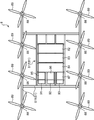
- FIG. 2 and 3 are views showing the configuration of the unmanned air vehicle 8
- FIG. 2 is a plan view of the unmanned air vehicle 8 as viewed from above
- FIG. 3 is a side view of the unmanned air vehicle 8.
- the unmanned air vehicle 8 of the present embodiment is a large unmanned air vehicle 8 m square when viewed from above.
- the unmanned airframe 8 includes an airframe 81, an engine 82, a generator 83, a fuel tank 84, an inverter 85, a battery 86, a converter 87, a motor 88, and a propeller 89 mounted on the airframe 81.
- the airframe 81 includes a main frame 811 having a rectangular frame shape when viewed from above, and a subframe 812 supported by the main frame 811 inside the main frame 811.
- a plurality of motors 88 are attached to the upper surface of the main frame 811 at predetermined intervals, and a propeller 89 is connected to each motor 88.
- eight motors 88 are attached to the upper surface of the main frame 811, and a propeller 89 is connected to each of the motors 88.
- the subframe 812 stores the mounting unit 8121 on which the engine 82, the generator 83, the fuel tank 84, the inverter 85, the battery 86, and the converter 87 are mounted, and people and cargo in order to realize the transport function of the unmanned aircraft 8. It has a storage portion 8122 made possible, and a leg portion 8123 that comes into contact with the ground or the like when the unmanned aircraft 8 lands.
- the engine 82 is driven by the fuel stored in the fuel tank 84, and the generator 83 generates electricity using the driving force of the engine 82 as a power source.
- the generator 83 is for realizing the power supply function of the unmanned aircraft 8.
- the AC power generated by the generator 83 is converted into DC power by the converter 87 and stored in the battery 86.
- the DC power stored in the battery 86 is reversely converted into AC power by the inverter 85 as needed and supplied to the motor 88.
- the motor 88 rotates, and the propeller 89 rotates according to the rotation of the motor 88, so that the unmanned vehicle 8 can fly.
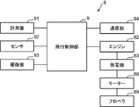
- the unmanned vehicle 8 further includes a flight control unit 9, a measuring instrument 91, a sensor 92, an imaging unit 93, and a communication unit 94.
- the flight control unit 9, the measuring instrument 91, the sensor 92, the imaging unit 93, and the communication unit 94 are provided at appropriate positions on the subframe 812.
- the measuring instrument 91 includes a gyro sensor that measures the tilt angle of the airframe 81 with respect to the gravity axis, an altimeter that measures the altitude from the ground based on the reflected wave obtained by sending ultrasonic waves from the airframe 81 toward the ground. It has a GPS receiver that measures the position of the aircraft 81 based on the received signal obtained from the satellite group. That is, the measuring instrument 91 measures the flight attitude with the gyro sensor, measures the altitude from the ground with the altimeter, and measures the flight position with the GPS receiver during the flight of the unmanned flying object 8. The measurement result of the measuring instrument 91 is input to the flight control unit 9.
- the sensor 92 is a sensor that detects the presence or absence of obstacles or the like around the machine body 81.
- the sensor 92 detects the presence or absence of obstacles or the like around the airframe 81 when the unmanned airframe 8 takes off, and detects the presence or absence of obstacles or the like in front of the airframe 81 during the flight of the unmanned airframe 8.
- the detection result of the sensor 92 is input to the flight control unit 9.
- the imaging unit 93 is an imaging camera that images the lower part of the machine body 81.
- the image pickup unit 93 takes an image of the lower part of the airframe 81 at the time of landing of the unmanned airframe 8, and acquires an image.
- the image acquired by the imaging unit 93 is input to the flight control unit 9.
- the communication unit 94 performs data communication with the management system 7 installed at the management base 6 described later.
- the flight control unit 9 monitors the data communication between the communication unit 94 and the management system 7, and is an unmanned aircraft based on the measurement result of the measuring instrument 91, the detection result of the sensor 92, and the image data of the imaging unit 93. Control flight including takeoff and landing of 8. The details of the control of the flight control unit 9 will be described later.
- a management system 7 is installed at the management base 6 in the target area.
- the management base 6 is also a departure base when a moving body including an unmanned flying object 8 stands by and moves. By consolidating the waiting areas of the moving bodies including the unmanned flying object 8 in the management base 6, it is possible to reduce the maintenance cost of the unmanned flying body 8 and the like.
- a management base transmission line 61 branched from the first transmission line 25 is connected to the management base 6.
- the number of management bases 6 in the target area is not particularly limited, and may be one base or a plurality of two or more bases.
- the location of the management base 6 in the target area is the power supply suitability that indicates the suitability of power supply when using the power supply function of the unmanned aircraft 8, and the suitability for avoiding the disaster in the event of a disaster in the target area. It is desirable to select it in consideration of disaster avoidance suitability.
- the power supply suitability is determined by the distance from the first power generation facility 21 installed in the target area, the transmission capacity of the first transmission line 25 connected to the first power generation facility 21, and the like.
- the management system 7 is a system that manages the power transmission system 2, the power transmission / distribution system 3, and the unmanned aircraft 8. As shown in the block diagram of FIG. 5, the management system 7 includes an arithmetic processing unit 71, an information input / output unit 72, a management side communication unit 73, and a database 74.
- the management system 7 does not need to be installed in the target area, and all or part of its functions may be outside the target area. For example, a command signal from a central ministry, a prefectural office, a cloud server, or the like outside the target area may be transmitted to the management base 6.
- the information input / output unit 72 accepts input of disaster index information which is an index of disaster occurrence in the target area and input of various information transmitted from the specific customer 4A.
- the disaster index information includes information such as precipitation, river water level, tide level, wind speed, and seismic intensity of an earthquake, meteorological warning information, and information indicating a road network blockage status.
- the information input / output unit 72 outputs instruction information indicating the instruction content regarding the handling of the unmanned aircraft 8 when the power supply function of the unmanned aircraft 8 is used at the management base 6 or the specific customer 4A. .. The details of this instruction information will be described later.
- the management side communication unit 73 performs data communication with the communication unit 94 of the unmanned aircraft 8.
- the database 74 stores the supply power index data that is an index for predicting the power supply amount of the power transmission system 2 and the demand power index data that is an index for predicting the demand power amount of the power transmission and distribution system 3. It is a department.
- the power supply index data includes past data on the amount of power supplied by the power transmission system 2 for each season, time zone, and weather change, the power supply and demand plan of the external power system 5 disclosed in the power trading market, and contracted purchased power. Includes data indicating the amount of power generation, maintenance plans for the first power generation facility 21 and the second power generation facility 22, maintenance status, accident information, data indicating the amount of power generation based on the failure occurrence probability, and the like.
- the demand power index data includes seasons, days of the week, time zones, special events, reservation status of accommodation facilities and restaurants, mobile terminal position information, past data for each weather change, and the like regarding the power demand amount of the power transmission and distribution system 3.
- the database 74 does not necessarily have to be stored in the storage unit of the management base 6, and may be stored in the cloud server.
- the arithmetic processing unit 71 performs various arithmetic processing for managing the power transmission system 2, the power transmission / distribution system 3, and the unmanned aircraft 8.
- the arithmetic processing unit 71 has an energy supply and demand monitoring unit 711, a power adjustment processing unit 712, a surplus power handling processing unit 713, a disaster determination unit 714, and a disaster response processing unit 715 as functional configurations.
- the arithmetic processing of the arithmetic processing unit 71 will be described with reference to FIGS. 6 to 10.
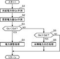
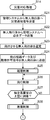
- FIG. 6 is a flowchart for explaining the power adjustment process and the surplus power handling process by the arithmetic processing unit 71
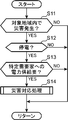
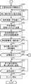
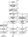
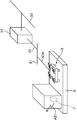
- FIGS. 7 to 10 are flowcharts for explaining the disaster response processing by the arithmetic processing unit 71.
- the energy supply and demand monitoring unit 711 predicts the power supply amount Qs of the power transmission system 2 based on the power supply index data stored in the database 74 (step S1), and stores the power supply system 74 in the database 74.
- the power demand Qd of the power transmission / distribution system 3 is predicted based on the stored power demand index data (step S2).
- the energy supply / demand monitoring unit 711 may be configured to output notification data for notifying each consumer 4 or the like of the power price based on the predicted power demand amount of the power transmission / distribution system 3. By confirming the electric power price indicated by the notification data, each consumer 4 can take measures such as suppressing the electric power demand.
- the energy supply / demand monitoring unit 711 determines whether or not the power supply amount Qs of the power transmission system 2 is less than the power demand Qd of the power transmission / distribution system 3 based on the prediction results of steps S1 and S2 (step S3). ).
- the power adjustment processing unit 712 utilizes the power supply function of the unmanned vehicle body 8 to use the unmanned vehicle body 8.
- a power adjustment process for supplying power from the generator 83 of No. 8 to the power transmission / distribution system 3 is performed (step S4).
- the power adjustment processing unit 712 outputs the power adjustment instruction information AS1 from the information input / output unit 72 in a state where the unmanned aircraft 8 is on standby at the management base 6.
- the power adjustment instruction information AS1 is instruction information indicating that the power supply function of the unmanned aircraft 8 can be used at the management base 6.
- the worker at the management base 6 can grasp that the power supply function of the unmanned aircraft 8 can be used at the management base 6.
- a worker connects a predetermined power cable 83A between the generator 83 of the unmanned vehicle 8 and the management base transmission line 61, and then starts driving the engine 82 of the unmanned vehicle 8. Will be done.
- the generator 83 generates electric power using the driving force of the engine 82 as a power source, and the electric power generated by the power generation is supplied from the unmanned vehicle 8 to the power transmission / distribution system 3.
- the unmanned vehicle 8 may be configured to detect the connection of the power cable 83A and automatically drive the engine 82.
- the power supply function of the unmanned vehicle 8 can be used to supply power from the unmanned vehicle 8 to the power transmission / distribution system 3.
- the power supply function of the unmanned vehicle 8 By utilizing the power supply function of the unmanned vehicle 8 and utilizing the unmanned vehicle 8 as an adjusting power source, it is possible to stabilize the power supply to the power transmission / distribution system 3.
- the transport function of the unmanned vehicle 8 can be used to transport people and cargo to the unmanned vehicle 8. That is, the unmanned aircraft 8 is not a facility specialized for supplying electric power when the electric power supply to the power transmission and distribution system 3 is insufficient, but is effectively used as a facility for transporting people and cargo in a normal state. As a result, it is possible to improve the utilization efficiency of the unmanned aircraft 8 that can be utilized as an adjustment power source.
- the power adjustment processing unit 712 uses the energy cost for procuring the power shortage from the external power system 5 and the power supply function of the unmanned aircraft 8 when the power supply shortage to the power transmission / distribution system 3 occurs. In addition to calculating the energy cost in the case of using the unmanned air vehicle 8, the transportation cost in the case of using the transportation function of the unmanned air vehicle 8 and the transportation cost by other transportation means may be calculated. In this case, the electric power adjustment processing unit 712 determines the usage mode of the transportation function and the electric power supply function of the unmanned aircraft 8 so that the total of the calculated energy cost and the transportation cost is the smallest.
- step S3 the energy supply and demand monitoring unit 711 determines whether or not the power supply Qs of the power transmission system 2 exceeds the power demand Qd of the power transmission and distribution system 3 (step S5). ..
- the surplus power handling processing unit 713 transmits the surplus power from the transmission system 2 to the hydrogen production facility 4B. Performs power processing.
- hydrogen can be produced in the hydrogen production facility 4B by utilizing the surplus electric power.
- the hydrogen produced in the hydrogen production facility 4B can be used, for example, as a fuel for the fuel cell power generation facility.
- the disaster determination unit 714 determines whether or not a disaster has occurred in the target area based on the disaster index information input to the information input / output unit 72 (step S11). ..
- step S11 If YES is determined in step S11 and the occurrence of a disaster in the target area is confirmed, the disaster determination unit 714 determines whether or not the power transmission / distribution system 3 is out of power (step S12).
- the disaster determination unit 714 determines whether or not it is necessary to supply power to the specific consumer 4A (step S13). Specifically, the disaster determination unit 714 determines the specific consumer 4A when the power failure of the power transmission / distribution system 3 continues beyond a predetermined time, or when the expected power failure recovery time of the power transmission / distribution system 3 exceeds the predetermined time. However, it is judged that power supply for disaster response is necessary.
- the disaster determination unit 714 may determine that a disaster has occurred by receiving a command signal from the outside such as a central ministry or a prefectural office via the management side communication unit 73.
- step S13 When YES is determined in step S13, that is, when a disaster occurs in the target area, a power failure of the power transmission / distribution system 3 and the necessity of supplying power to the specific customer 4A are all confirmed.
- the disaster response processing unit 715 performs disaster response processing (step S14). That is, as a disaster response process, the disaster response processing unit 715 flies the unmanned vehicle 8 to the specific customer 4A, and at the same time, the premises system installed in the premises of the specific customer 4A from the generator 83 of the unmanned aircraft 8 Power is supplied to 4A1 (see FIGS. 12 to 14).
- the unmanned aircraft 8 when a power failure occurs in the power transmission / distribution system 3, electric power can be supplied from the unmanned aircraft 8 to the premises system 4A1 of the specific consumer 4A.
- the road network may be cut off in the vicinity of the specific customer 4A, resulting in an isolated state.
- the unmanned aircraft 8 has an air route as a movement route, it can move to the specific customer 4A and can supply electric power to the premises system 4A1 of the specific customer 4A. can.
- the cargo such as daily necessities is stored in the storage unit 8122 of the unmanned air vehicle 8, and the unmanned air vehicle 8 moves to the specified customer 4A in that state to transport the daily necessities, medicines and various other supplies. Is also possible.
- the disaster response processing by the disaster response processing unit 715 and the control of the unmanned aircraft 8 by the flight control unit 9 according to the disaster response processing will be specifically described below.
- the disaster response processing unit 715 sends a disaster notification signal from the management side communication unit 73 to notify the specific consumer 4A that the power supply for the disaster response is necessary. It is transmitted to 8 (step S21).
- the disaster notification signal is transmitted to all the unmanned aircraft 8.
- the transmitted disaster notification signal is received by the communication unit 94 of the unmanned aircraft 8.
- the flight control unit 9 of the unmanned aircraft 8 has, as shown in FIG. 12, the pre-takeoff detection data BS1 showing the detection result around the aircraft 81 by the sensor 92 before takeoff, and the fuel tank 84.
- the remaining fuel data BS2 indicating the remaining fuel amount is transmitted from the communication unit 94 to the management system 7 (step S22).
- the transmitted pre-takeoff detection data BS1 and residual fuel data BS2 are received by the management side communication unit 73.
- the disaster response processing unit 715 selects the unmanned vehicle 8 to be flown to the specific customer 4A (step S23).
- the disaster response processing unit 715 determines that an unmanned airframe 8 having no obstacles around the aircraft 81 is an unmanned airframe 8 that does not hinder takeoff, based on the pre-takeoff detection data BS1.
- the administrator of the management system 7 may refer to the pre-takeoff detection data BS1 to determine that the unmanned aircraft 8 does not interfere with takeoff.
- the remaining fuel amount indicated by the residual fuel data BS2 does not fall below the total of the fuel for flight and the fuel for disaster response power generation, and after taking off from the management base 6, the specified customer An unmanned vehicle 8 to be flown to a specific customer 4A is selected if the time required to arrive at 4A does not exceed a predetermined time.
- the fuel for flight is the fuel required for round-trip flight between the management base 6 and the specific customer 4A
- the fuel for disaster response power generation is the power supply to the specific customer 4A. It is the fuel needed to generate electricity at the time. If the fuel stockpile of the specified customer 4A is sufficiently secured, the unmanned aircraft 8 having the fuel remaining amount required for the outbound route from the management base 6 to the specified customer 4A is selected. You may.
- an inverter may be required when supplying electric power from the generator 83 of the unmanned aircraft 8 to the premises system 4A1 of the specific customer 4A.
- the voltage of the power generated by the generator 83 may be different from the voltage that can be used in the premises system 4A1, and in such a case, it is necessary for the specific customer 4A to prepare an inverter.
- not all specific consumers 4A will be provided with the inverter. Therefore, it is desirable to register in advance the information indicating the presence or absence of the inverter in the specific consumer 4A in the database 74.
- the worker at the management base 6 can confirm whether or not the inverter exists in the specific customer 4A before the flight of the unmanned vehicle 8 based on the information registered in the database 74. As a result of the confirmation, when it is found that the inverter does not exist in the specific customer 4A, the worker mounts the inverter on the unmanned vehicle 8. As a result, it is possible to smoothly proceed with the power supply after the unmanned aircraft 8 arrives at the specific consumer 4A.
- the disaster response processing unit 715 shows the flight path data AS2 (FIG. 12) indicating the flight route from the management base 6 to the specific customer 4A. And the takeoff permission signal is transmitted to the unmanned aircraft 8 selected by the management side communication unit 73 (step S24).
- the disaster response processing unit 715 stops the use corresponding to the power adjustment processing of the unmanned aircraft 8.
- the flight to the specific customer 4A is prioritized by transmitting the flight path data AS2 and the takeoff permission signal.
- the transmitted flight path data AS2 and takeoff clearance signal are received by the communication unit 94 of the unmanned aircraft 8.
- the flight control unit 9 of the unmanned aircraft 8 performs takeoff control for starting the engine 82 and taking off the aircraft 81 from the management base 6 as shown in FIG. 12 (step S25).
- the flight control unit 9 causes the generator 83 to generate electric power by using the driving force of the started engine 82 as a power source, and rotates the motor 88 by the generated electric power.
- the propeller 89 is rotationally driven by the motor 88, and the unmanned aircraft 8 takes off.
- the flight control unit 9 flies the aircraft 81 to the specific customer 4A along the flight path indicated by the flight path data AS2 while monitoring the measurement result of the measuring instrument 91 and the detection result of the sensor 92. Flight control is performed (step S26).
- the flight control unit 9 determines whether or not the unmanned aircraft 8 has arrived over the specific customer 4A (step S27), and when the arrival is confirmed, the flight control unit 9 controls the landing of the unmanned aircraft 8. (Step S28).
- FIG. 10 is a subroutine showing the details of the landing control in step S28.
- the flight control unit 9 causes the image pickup unit 93 to take an image of the vicinity of the predetermined landing location 4A2 set in or near the premises of the specific customer 4A.
- the image data BS3 of the peripheral image obtained by the imaging is transmitted from the communication unit 94 to the management system 7 (step S42).
- the flight control unit 9 determines whether or not there is an obstacle to landing at the planned landing location 4A2 based on the peripheral image data BS3 (step S43).
- the management system 7 may determine whether or not there is an obstacle to landing, instead of the flight control unit 9.
- the flight control unit 9 manages the landing permission request signal BS4 requesting landing permission from the communication unit 94. It is transmitted to the system 7 (step S44).
- the peripheral image data BS3 and the landing permission request signal BS4 transmitted from the unmanned aircraft 8 are received by the management side communication unit 73.
- the administrator of the management system 7 inputs an instruction to transmit the landing permission signal AS3 in response to the landing permission request signal BS4.
- the disaster response processing unit 715 transmits the landing permission signal AS3 from the management side communication unit 73 to the unmanned aircraft 8.
- the flight control unit 9 of the unmanned aircraft 8 determines whether or not the transmitted landing permission signal AS3 has been received by the communication unit 94 (step S45), and when the reception is confirmed, the aircraft is located at the planned landing site 4A2.
- the 81 is landed (step S46), and then the engine 82 is stopped (step S47).
- the flight control unit 9 takes off the unmanned aircraft 8 as part of the disaster response processing by the disaster response processing unit 715 (S25), and the flight control unit 9 is unmanned along the flight path indicated by the flight path data AS2.
- the flight control (S26) for flying the aircraft 8 and the landing control (S28) for landing the unmanned aircraft 8 are executed.
- the unmanned aircraft 8 can automatically perform flight including takeoff and landing under the control of the flight control unit 9.
- the flight control unit 9 determines that there is an obstacle to landing at the planned landing site 4A2 based on the peripheral image data BS3 (YES in step S43). Then, the flight control unit 9 searches for a landing candidate place 4AS whose distance from the planned landing place 4A2 is within a predetermined allowable range and does not hinder landing (step S48), and the landing candidate place 4AS is found by the search. It is determined whether or not the operation has been performed (step S49).
- step S49 When it is determined as YES in step S49 and it is confirmed that the landing candidate location 4AS has been found, the flight control unit 9 receives the landing permission request signal and the landing permission request signal with the management system 7 in the same manner as in steps S44 and S45. After transmitting and receiving the landing permission signal, the aircraft 81 is landed at the landing candidate location 4AS (step S50), and then the engine 82 is stopped (step S51).
- step S49 when it is determined as NO in step S49 and it is confirmed that the landing candidate location 4AS has not been found, the flight control unit 9 flies the aircraft 81 in the direction of returning to the management base 6 (step S53).
- step S54 the flight control unit 9 lands the aircraft 81 at the management base 6 (step S54) and then stops the engine 82 (step S55).
- the disaster response processing unit 715 After landing at the planned landing site 4A2 or the candidate landing site 4AS by the above landing control will be described by returning to FIG.
- the disaster response processing unit 715 outputs the disaster response instruction information AS4 (FIG. 14) from the information input / output unit 72 (step S29).
- the disaster response instruction information AS4 is instruction information indicating that the power supply function of the unmanned aircraft 8 can be used by the specific consumer 4A.
- the disaster response instruction information AS4 is transmitted from the information input / output unit 72 to the specific customer 4A. By recognizing the disaster response instruction information AS4, the worker of the specific consumer 4A can grasp that the power supply function of the unmanned aircraft 8 can be used by the specific consumer 4A.
- the power supply function of the unmanned air vehicle 8 can be used when the unmanned air vehicle 8 lands on the specific customer 4A at the time of a disaster in the target area. good.
- the output of the disaster response instruction information AS4 from the information input / output unit 72 is omitted.
- the worker of the specified customer 4A connects a predetermined power cable 83A between the generator 83 of the unmanned aircraft 8 landing at the planned landing site 4A2 or the landing candidate site 4AS and the premises system 4A1, and then makes an unmanned flight.
- the work of starting the driving of the engine 82 of the body 8 is performed.
- the generator 83 generates electric power using the driving force of the engine 82 as a power source, and the electric power generated by the power generation is supplied from the unmanned aircraft 8 to the premises system 4A1 (step S30).
- the unmanned vehicle 8 may be configured to detect the connection of the power cable 83A and automatically drive the engine 82.
- the specific consumer 4A may have an original power source capable of supplying power to the premises system 4A1 during a power failure of the power transmission / distribution system 3.
- an original power source include a power generation facility using renewable energy and a storage battery prepared for disaster countermeasures.
- the disaster response processing unit 715 refers to the database 74 and determines whether or not the original power source (power generation equipment using renewable energy, storage battery, etc.) connected to the premises system 4A1 exists in the specific consumer 4A. To judge. When the existence of the original power source is confirmed by this determination, the disaster response processing unit 715 has a reference voltage and a reference voltage for enabling the original power source and the generator 83 to supply electric power to the premises system 4A1 in synchronization with each other. The reference frequency is transmitted from the management side communication unit 73 to the specific customer 4A. In response to this, the original power supply of the specific consumer 4A adjusts the voltage and frequency of the AC power supplied by the specific consumer 4A to values that match the reference voltage and the reference frequency. The process of adjusting the voltage and frequency of the original power source in this way may be performed by the control system provided in the specific customer 4A, or may be performed by the management system 7 (disaster response processing unit 715).
- the flight control unit 9 monitors the remaining amount of fuel in the fuel tank 84. Specifically, the flight control unit 9 determines whether or not the remaining amount of fuel in the fuel tank 84 has fallen below a predetermined warning value (step S31), and when it is confirmed that the remaining amount of fuel has fallen below the predetermined warning value, the remaining amount of fuel is low. The remaining fuel warning information indicating that effect is transmitted from the communication unit 94 to the management system 7 (step S32).
- the disaster response processing unit 715 transmits the fuel storage amount information indicating the storage amount of the fuel stored in the specific customer 4A via the information input / output unit 72. Acquire (step S33).
- the disaster response processing unit 715 determines whether or not the fuel storage amount indicated by the fuel storage amount information has fallen below the predetermined warning value (step S34), and when it is confirmed that the fuel storage amount has fallen below the predetermined warning value, the management base 6 is contacted.
- the other unmanned vehicle 8 is made to transport the fuel to the specific consumer 4A (step S35). This makes it possible to refuel the specific consumer 4A.
- the fuel storage amount information may be transmitted to the outside via the management side communication unit 73, or the external device may centrally manage the fuel storage amount information in each region.
- the unmanned aircraft 8 may be provided with a notification mechanism such as an indicator light for notifying the worker of the specific consumer 4A of the residual fuel warning information.
- a notification mechanism such as an indicator light for notifying the worker of the specific consumer 4A of the residual fuel warning information.
- the worker of the specific customer 4A can grasp that the remaining fuel amount in the unmanned aircraft 8 that is supplying power to the premises system 4A1 has decreased, and the specific customer 4A responds accordingly.
- the stored fuel can be replenished to the unmanned aircraft 8.
- the disaster determination unit 714 determines whether or not the power failure of the power transmission / distribution system 3 has been restored (step S36). If the result is YES and the recovery of the power failure is confirmed, that is, if it is confirmed that the power supply for the disaster response to the specific customer 4A is no longer necessary, the disaster response processing unit 715 will perform the disaster response.
- the end command signal for instructing the end of the power supply for the above is transmitted from the management side communication unit 73 to the unmanned aircraft 8 (step S37).
- the flight control unit 9 of the unmanned aircraft 8 determines whether or not the transmitted end command signal has been received by the communication unit 94 (step S38), and when the reception is confirmed, the engine 82 is stopped to cause a disaster.
- the power supply for the response is terminated (step S39). In this way, the unmanned vehicle 8 can automatically end the power supply for disaster response under the control of the flight control unit 9.
- the work of disconnecting the connection of the power cable 83A between the generator 83 and the premises system 4A1 is performed by the worker of the specific customer 4A.
- the flight control unit 9 calculates the amount of fuel required for the flight from the specific customer 4A to the management base 6, and the information of the calculated value is transmitted to the specific customer 4A by the notification mechanism or the like. It may be configured to inform the workers of. In this case, the worker of the specific consumer 4A can replenish the unmanned aviation body 8 with the fuel required for the unmanned aviation body 8 to return to the management base 6.
- the flight control unit 9 controls the takeoff of the unmanned aircraft 8 from the specific customer 4A, the flight control during the flight from the specific customer 4A to the management base 6, and the landing at the management base 6. Perform landing control. As a result, the unmanned aircraft 8 automatically returns from the specific customer 4A to the management base 6.
- the energy supply system includes a power transmission system installed in the target area and including a first power generation facility that generates power using renewable energy and a second power generation facility that generates power using fossil fuel.
- a power transmission / distribution system in which power is transmitted from the power transmission system and supplies power to consumers in the target area, a mobile body having a transportation function for transporting freight and a power supply function for supplying power to the outside, It includes the power transmission system, the power transmission / distribution system, and a management system for managing the mobile body.
- the management system predicts the power supply amount of the power transmission system and the power demand amount of the power transmission and distribution system, and when the power supply amount is less than the power demand amount, the power supply function of the mobile body is used. Then, a power adjustment process for supplying power from the moving body to the power transmission / distribution system is performed.
- the amount of power supplied by the transmission system falls below the amount of power required by the transmission and distribution system due to fluctuations in the output of the first power generation facility that uses renewable energy, resulting in insufficient power supply to the transmission and distribution system.
- the power supply function of the mobile body can be used to supply power from the mobile body to the power transmission and distribution system.
- the transport function of the mobile body can be used to transport the cargo to the mobile body.
- the mobile body is not a facility specialized for power supply when the power supply to the power transmission and distribution system is insufficient, but is effectively used as a facility for transporting cargo in normal times. As a result, it is possible to improve the utilization efficiency of the mobile body that can be utilized as an adjustment power source.
- the above energy supply system may be installed in the target area and further equipped with a hydrogen production facility that electrolyzes water to produce hydrogen.
- the management system performs a surplus power handling process for transmitting surplus power from the power transmission system to the hydrogen production facility when the power supply amount of the power transmission system exceeds the demand power amount of the power transmission and distribution system. Is preferable.
- hydrogen can be produced in the hydrogen production facility by using the surplus electric power.
- the hydrogen produced in the hydrogen production facility can be used as fuel for the fuel cell power generation facility, for example.
- the moving body includes an airframe, an engine mounted on the airframe, a generator mounted on the airframe to realize the power supply function, and a transport function. It may be an unmanned airframe having a storage unit capable of storing cargo.
- the unmanned air vehicle is a mobile body whose movement route is an air route.
- Such an unmanned air vehicle is not affected by traffic congestion or road closures due to road network blockage, unlike a mobile body that uses a land route as a movement route, and a coastal area like a mobile body that uses a sea route as a movement route. You are not restricted to moving around.
- the management system is a disaster response process for supplying electric power from the unmanned vehicle to the specific consumer when a power failure occurs in the power transmission and distribution system at the time of a disaster in the target area. May be the one that does.
- the disaster response process preferably causes the unmanned vehicle to fly along a predetermined flight path to a specific customer designated as a disaster prevention base in the target area, and the identification from the generator of the unmanned vehicle. It is a process to supply electric power to the premises system installed on the premises of the customer.
- power in the event of a power outage in the power transmission and distribution system in the event of a disaster in the target area, power can be supplied from the generator of the unmanned aircraft to the premises system of a specific customer designated as a disaster prevention base. can.
- the road network may be cut off in the vicinity of a specific customer, resulting in an isolated state.
- an unmanned air vehicle whose movement route is an air route can move to a specific customer and can supply electric power to the premises system of the specific customer.
- it is also possible to transport cargo such as daily necessities by storing cargo such as daily necessities in the storage unit of the unmanned air vehicle and moving the unmanned air vehicle to a specific customer in that state.
- the specific consumer may have a unique power source capable of supplying AC power to the premises system during a power failure of the power transmission / distribution system.
- the management system transmits a reference voltage and a reference frequency for supplying AC power to the premises system in synchronization with the original power source and the generator at the time of the disaster response process to the specific consumer. It is preferable to do so.
- the unmanned vehicle further includes an imaging unit, a communication unit that performs data communication between the management system, and a flight control unit that controls flight including takeoff and landing. You may be doing it.
- the flight control unit starts the engine in response to the reception of the flight path and takeoff permission signal transmitted from the management system by the communication unit with the start of the disaster response process. Takeoff control is performed to take off the aircraft from the departure base, and after takeoff, flight control is performed to fly the aircraft to the specific customer along the flight path. Upon arriving above the customer, it is preferable to perform landing control for landing the aircraft on the specific customer.
- the landing control causes the imaging unit to image the area around a predetermined landing location, transmits the peripheral image obtained by the imaging to the management system via the communication unit, and causes a landing permission signal from the management system. Is received, the aircraft is landed on the specific customer and the engine is stopped.
- the flight control unit starts the engine in response to the flight path transmitted from the management system being received by the communication unit with the start of the disaster response process, and the aircraft is started from the departure base.
- the aircraft is controlled to fly to the specific customer along the flight path, and the flight control causes the aircraft to fly over the specific customer.
- the aircraft may be subject to landing control for landing on the specific consumer.
- the landing control is performed by causing the imaging unit to image the area around a predetermined landing site and transmitting a peripheral image obtained by the imaging to the management system via the communication unit, and the landing schedule based on the peripheral image. It is a control that determines whether or not there is an obstacle to landing at a place, and if there is no obstacle, the aircraft is landed on the specific customer and the engine is stopped.
- the unmanned aircraft has a flight control unit, which controls takeoff during takeoff of the unmanned aircraft, flight control during flight along a predetermined flight path, and landing control during landing.
- the unmanned aircraft can automatically perform flight including takeoff and landing under the control of the flight control unit.
- the flight control unit may perform the landing from the planned landing location based on the peripheral image.
- a landing candidate site whose distance is within a predetermined allowable range and which does not hinder landing is searched for, and when the landing candidate site is found, the aircraft is landed at the landing candidate site, the engine is stopped, and the landing is performed.
- the aircraft may be flown in the direction of returning to the departure base, and the aircraft may be landed at the departure base to stop the engine.
- the unmanned aircraft In the event of a disaster in the target area, there is a possibility that damage such as flooding or falling obstacles may occur at the planned landing site of a specific customer. In this case, the landing of the unmanned aircraft at the planned landing site may be hindered. Therefore, the unmanned aircraft automatically searches for a landing candidate location that does not interfere with landing under the control of the flight control unit, and when the landing candidate location is found, it automatically lands at that location, while the landing candidate location If it is not found, it will return to the departure base and land automatically.
Landscapes
- Engineering & Computer Science (AREA)
- Power Engineering (AREA)
- Aviation & Aerospace Engineering (AREA)
- Mechanical Engineering (AREA)
- Transportation (AREA)
- Remote Sensing (AREA)
- Chemical & Material Sciences (AREA)
- Combustion & Propulsion (AREA)
- Sustainable Energy (AREA)
- Life Sciences & Earth Sciences (AREA)
- Sustainable Development (AREA)
- Radar, Positioning & Navigation (AREA)
- Physics & Mathematics (AREA)
- General Physics & Mathematics (AREA)
- Automation & Control Theory (AREA)
- Microelectronics & Electronic Packaging (AREA)
- Management, Administration, Business Operations System, And Electronic Commerce (AREA)
- Supply And Distribution Of Alternating Current (AREA)
Abstract
Description
上述した具体的実施形態には以下の構成を有する発明が主に含まれている。
Claims (8)
- 対象地域内に設置され、再生可能エネルギーを用いて発電する第1発電設備と化石燃料を用いて発電する第2発電設備とを含む送電系統と、
前記送電系統から電力が伝送され、前記対象地域内の需要家へ電力を供給する送配電系統と、
貨物を輸送する輸送機能と外部に電力を供給する電力供給機能とを有する移動体と、
前記送電系統、前記送配電系統及び前記移動体を管理する管理システムと、を備え、
前記管理システムは、前記送電系統の供給電力量と前記送配電系統の需要電力量とを予測し、前記供給電力量が前記需要電力量を下回る場合、前記移動体の前記電力供給機能を利用して、前記移動体から前記送配電系統へ電力を供給させる電力調整処理を行う、エネルギー供給システム。 - 前記対象地域内に設置され、水を電気分解して水素を製造する水素製造設備を更に備え、
前記管理システムは、前記送電系統の前記供給電力量が前記送配電系統の前記需要電力量を上回る場合、余剰電力を前記送電系統から前記水素製造設備へ伝送させる余剰電力対応処理を行う、請求項1に記載のエネルギー供給システム。 - 前記移動体は、機体と、前記機体に搭載されるエンジンと、前記機体に搭載され、前記電力供給機能を実現するための発電機と、前記輸送機能の実現のために貨物を収納可能な収納部と、を有した無人飛行体である、請求項1又は2に記載のエネルギー供給システム。
- 前記管理システムは、前記対象地域の災害発生時において前記送配電系統に停電が生じた場合に、前記無人飛行体から前記特定の需要家に電力を供給する災害対応処理を行い、
前記災害対応処理は、前記対象地域の防災拠点に指定された特定の需要家へ前記無人飛行体を所定の飛行経路に沿って飛行させ、前記無人飛行体の前記発電機から前記特定の需要家の構内に設置された構内系統へ電力を供給させる処理である、請求項3に記載のエネルギー供給システム。 - 前記送配電系統の停電中に前記構内系統に交流電力を供給可能な独自電源が前記特定の需要家に存在する場合、前記管理システムは、前記災害対応処理時に、前記独自電源と前記発電機とが同期して前記構内系統へ交流電力を供給するための基準電圧及び基準周波数を前記特定の需要家に送信する、請求項4に記載のエネルギー供給システム。
- 前記無人飛行体は、撮像部と、前記管理システムとの間でデータ通信を行う通信部と、離陸及び着陸を含む飛行の制御を行う飛行制御部と、を更に有し、
前記飛行制御部は、
前記災害対応処理の開始に伴い前記管理システムから送信された前記飛行経路及び離陸許可信号が前記通信部により受信されるのに応じて、前記エンジンを始動させて出発拠点から前記機体を離陸させる離陸制御を行い、
離陸後においては、前記飛行経路に沿って前記特定の需要家へ前記機体を飛行させる飛行制御を行い、
前記飛行制御により前記機体が前記特定の需要家の上空に到着すると、前記機体を前記特定の需要家に着陸させる着陸制御を行い、
前記着陸制御は、所定の着陸予定場所周辺を前記撮像部に撮像させて当該撮像による周辺画像を前記通信部を介して前記管理システムへ送信させると共に、前記管理システムからの着陸許可信号を受信すると前記機体を前記特定の需要家に着陸させて前記エンジンを停止させる制御である、請求項4又は5に記載のエネルギー供給システム。 - 前記無人飛行体は、撮像部と、前記管理システムとの間でデータ通信を行う通信部と、離陸及び着陸を含む飛行の制御を行う飛行制御部と、を更に有し、
前記飛行制御部は、
前記災害対応処理の開始に伴い前記管理システムから送信された前記飛行経路が前記通信部により受信されるのに応じて、前記エンジンを始動させて出発拠点から前記機体を離陸させる離陸制御を行い、
離陸後においては、前記飛行経路に沿って前記特定の需要家へ前記機体を飛行させる飛行制御を行い、
前記飛行制御により前記機体が前記特定の需要家の上空に到着すると、前記機体を前記特定の需要家に着陸させる着陸制御を行い、
前記着陸制御は、所定の着陸予定場所周辺を前記撮像部に撮像させて当該撮像による周辺画像を前記通信部を介して前記管理システムへ送信させると共に、前記周辺画像に基づき前記着陸予定場所への着陸の支障の有無を判定し、支障が無い場合には前記機体を前記特定の需要家に着陸させて前記エンジンを停止させる制御である、請求項4又は5に記載のエネルギー供給システム。 - 前記飛行制御部は、前記着陸制御において前記着陸予定場所への着陸に支障が有ることが確認された場合には、
前記周辺画像に基づいて、前記着陸予定場所からの距離が所定の許容範囲内で且つ着陸に支障が無い着陸候補場所を探索し、
前記着陸候補場所が発見されたときには、当該着陸候補場所に前記機体を着陸させて前記エンジンを停止させ、
前記着陸候補場所が発見されなかったときには、前記出発拠点に戻る方向に前記機体を飛行させると共に、前記機体を前記出発拠点に着陸させて前記エンジンを停止させる、請求項7に記載のエネルギー供給システム。
Priority Applications (2)
| Application Number | Priority Date | Filing Date | Title |
|---|---|---|---|
| JP2022511854A JP7422216B2 (ja) | 2020-04-01 | 2021-03-17 | エネルギー供給システム |
| US17/916,039 US12244149B2 (en) | 2020-04-01 | 2021-03-17 | Energy supply system |
Applications Claiming Priority (2)
| Application Number | Priority Date | Filing Date | Title |
|---|---|---|---|
| JP2020066217 | 2020-04-01 | ||
| JP2020-066217 | 2020-04-01 |
Publications (1)
| Publication Number | Publication Date |
|---|---|
| WO2021200170A1 true WO2021200170A1 (ja) | 2021-10-07 |
Family
ID=77927235
Family Applications (1)
| Application Number | Title | Priority Date | Filing Date |
|---|---|---|---|
| PCT/JP2021/010893 Ceased WO2021200170A1 (ja) | 2020-04-01 | 2021-03-17 | エネルギー供給システム |
Country Status (3)
| Country | Link |
|---|---|
| US (1) | US12244149B2 (ja) |
| JP (1) | JP7422216B2 (ja) |
| WO (1) | WO2021200170A1 (ja) |
Families Citing this family (2)
| Publication number | Priority date | Publication date | Assignee | Title |
|---|---|---|---|---|
| JP7632154B2 (ja) * | 2021-07-27 | 2025-02-19 | トヨタ自動車株式会社 | エネルギー管理システム |
| WO2024118965A1 (en) * | 2022-12-01 | 2024-06-06 | Johnson Kara E | Aircraft takeoff and landing apparatus |
Citations (7)
| Publication number | Priority date | Publication date | Assignee | Title |
|---|---|---|---|---|
| JPH0491638A (ja) * | 1990-08-06 | 1992-03-25 | Sanyo Electric Co Ltd | エネルギーシステム |
| JPH0576145A (ja) * | 1991-09-12 | 1993-03-26 | Fuji Electric Co Ltd | 電気エネルギー流通方法 |
| JP2008245454A (ja) * | 2007-03-28 | 2008-10-09 | Hitachi Ltd | 災害時対応電力供給方法およびシステム |
| JP2010148350A (ja) * | 2008-12-19 | 2010-07-01 | Siemens Ag | 送電線網を安定させるための装置 |
| JP3163946U (ja) * | 2007-10-09 | 2010-11-11 | スイス・ハイドロゲン・パワー・エスエイチピー・エス アー | 再生可能エネルギーを生成して貯蔵するための装置 |
| US20200070680A1 (en) * | 2018-08-30 | 2020-03-05 | Honda Motor Co., Ltd. | Vehicle-to-grid energy for use with hydrogen generation |
| JP2020082935A (ja) * | 2018-11-21 | 2020-06-04 | 株式会社荏原製作所 | 水素搬送装置、および水素搬送方法 |
Family Cites Families (11)
| Publication number | Priority date | Publication date | Assignee | Title |
|---|---|---|---|---|
| RU2011118460A (ru) | 2008-10-07 | 2012-11-20 | Премиум Пауэр Корпорейшн (Us) | Система и способ для транспортировки энергии |
| WO2017070648A1 (en) * | 2015-10-22 | 2017-04-27 | Delta Energy & Communications, Inc. | Augmentation, expansion and self-healing of a geographically distributed mesh network using unmanned aerial vehicle technology |
| US11600996B2 (en) * | 2017-03-24 | 2023-03-07 | The Noco Company | Electric vehicle (EV) fast recharge station and system |
| WO2019079394A2 (en) * | 2017-10-17 | 2019-04-25 | Top Flight Technologies, Inc. | PORTABLE LAUNCH SYSTEM |
| US10589969B2 (en) * | 2018-04-25 | 2020-03-17 | Rinaldo Brutoco | System, method and apparatus for widespread commercialization of hydrogen as a carbon-free alternative fuel source |
| CN108973979B (zh) * | 2018-07-18 | 2021-09-28 | 乾碳国际公司 | 混动车辆预测性功率控制系统方案 |
| US12038746B2 (en) * | 2018-07-27 | 2024-07-16 | California Institute Of Technology | Modular and dynamically reconfigurable flying systems encompassing flying vehicle modules |
| WO2021069069A1 (en) * | 2019-10-09 | 2021-04-15 | Ejzenberg Geoffrey | A cyber-physical hybrid electric autonomous or semi-autonomous off-highway dump truck for surface mining industry |
| US11298063B2 (en) * | 2019-10-20 | 2022-04-12 | Bao Q Tran | Hydrogen powered device |
| CA3196646A1 (en) * | 2020-10-27 | 2022-05-05 | James M. Ewan | Hydrogen transport, distribution and storage system, method and apparatus |
| US11747781B1 (en) * | 2022-03-21 | 2023-09-05 | Nuvve Corporation | Intelligent local energy management system at local mixed power generating sites for providing grid services |
-
2021
- 2021-03-17 JP JP2022511854A patent/JP7422216B2/ja active Active
- 2021-03-17 US US17/916,039 patent/US12244149B2/en active Active
- 2021-03-17 WO PCT/JP2021/010893 patent/WO2021200170A1/ja not_active Ceased
Patent Citations (7)
| Publication number | Priority date | Publication date | Assignee | Title |
|---|---|---|---|---|
| JPH0491638A (ja) * | 1990-08-06 | 1992-03-25 | Sanyo Electric Co Ltd | エネルギーシステム |
| JPH0576145A (ja) * | 1991-09-12 | 1993-03-26 | Fuji Electric Co Ltd | 電気エネルギー流通方法 |
| JP2008245454A (ja) * | 2007-03-28 | 2008-10-09 | Hitachi Ltd | 災害時対応電力供給方法およびシステム |
| JP3163946U (ja) * | 2007-10-09 | 2010-11-11 | スイス・ハイドロゲン・パワー・エスエイチピー・エス アー | 再生可能エネルギーを生成して貯蔵するための装置 |
| JP2010148350A (ja) * | 2008-12-19 | 2010-07-01 | Siemens Ag | 送電線網を安定させるための装置 |
| US20200070680A1 (en) * | 2018-08-30 | 2020-03-05 | Honda Motor Co., Ltd. | Vehicle-to-grid energy for use with hydrogen generation |
| JP2020082935A (ja) * | 2018-11-21 | 2020-06-04 | 株式会社荏原製作所 | 水素搬送装置、および水素搬送方法 |
Also Published As
| Publication number | Publication date |
|---|---|
| JPWO2021200170A1 (ja) | 2021-10-07 |
| US20230170702A1 (en) | 2023-06-01 |
| US12244149B2 (en) | 2025-03-04 |
| JP7422216B2 (ja) | 2024-01-25 |
Similar Documents
| Publication | Publication Date | Title |
|---|---|---|
| KR102607816B1 (ko) | 무인항공기용 충전장치 및 제어방법 | |
| US11273719B2 (en) | System and method for reduction of power consumption and emissions of marine vessels | |
| AU2018264148B2 (en) | Charging a rechargeable battery of an unmanned aerial vehicle in flight using a high voltage power line | |
| US10919626B2 (en) | Charging a rechargeable battery of an unmanned aerial vehicle in flight using a high voltage power line | |
| US20220081923A1 (en) | Storage unit for an unmanned aerial vehicle | |
| US9387928B1 (en) | Multi-use UAV docking station systems and methods | |
| CN112109576B (zh) | 一种无人机自主循迹充电方法及装置 | |
| EP3124380A1 (fr) | Station d'accueil de drone et ensemble de gestion d'une telle station d'accueil | |
| US9878787B2 (en) | System and method for operating unmanned aircraft | |
| EP3486179B1 (en) | Inpecting utilities by means of an unmanned aerial vehicle and charging a rechargeable battery of the vehicle in flight using a high voltage power line and method and apparatus for generating a flight plan for the vehicle | |
| JP2017131019A (ja) | 送電設備の点検システム | |
| KR102037731B1 (ko) | 비행안전성 향상을 위한 드론통제시스템 | |
| JP7422216B2 (ja) | エネルギー供給システム | |
| CN122048214A (zh) | 一种面向城市末端低空物流的数字孪生物流路径动态优化系统 | |
| JP2026069549A (ja) | 架空線巡視点検システムおよび架空線巡視点検方法 | |
| JP7270440B2 (ja) | 無線電力伝送システムおよび無線電力伝送方法 | |
| CN117151432A (zh) | 一种用于避险模式的无人机自动机场的分配方法 | |
| CN117437814B (zh) | 一种基于气象站和基站的协同飞控方法、设备及存储介质 | |
| RU2821208C1 (ru) | Интеллектуальная система автоматического дистанционного мониторинга состояния и безопасности ЛЭП в непрерывном режиме | |
| Pratap et al. | Challenges of remote border monitoring | |
| RU2829914C1 (ru) | Интеллектуальная система автоматического дистанционного мониторинга состояния и безопасности высоковольтных ЛЭП с применением беспилотных летательных аппаратов | |
| WO2025195818A1 (en) | Maintenance system for offshore wind turbines | |
| CN121485075A (zh) | 一种基于光储充一体化的低空飞行器地面补能系统及其控制方法 | |
| CN121778236A (zh) | 一种高压杆塔无人机自动充电基站系统及其充电方法 |
Legal Events
| Date | Code | Title | Description |
|---|---|---|---|
| 121 | Ep: the epo has been informed by wipo that ep was designated in this application |
Ref document number: 21779044 Country of ref document: EP Kind code of ref document: A1 |
|
| ENP | Entry into the national phase |
Ref document number: 2022511854 Country of ref document: JP Kind code of ref document: A |
|
| NENP | Non-entry into the national phase |
Ref country code: DE |
|
| 122 | Ep: pct application non-entry in european phase |
Ref document number: 21779044 Country of ref document: EP Kind code of ref document: A1 |
|
| WWG | Wipo information: grant in national office |
Ref document number: 17916039 Country of ref document: US |