WO2021200014A1 - センサ及び電子機器 - Google Patents
センサ及び電子機器 Download PDFInfo
- Publication number
- WO2021200014A1 WO2021200014A1 PCT/JP2021/009800 JP2021009800W WO2021200014A1 WO 2021200014 A1 WO2021200014 A1 WO 2021200014A1 JP 2021009800 W JP2021009800 W JP 2021009800W WO 2021200014 A1 WO2021200014 A1 WO 2021200014A1
- Authority
- WO
- WIPO (PCT)
- Prior art keywords
- sensor
- layer
- pressure
- pressure sensor
- deformed
- Prior art date
Links
Images


Classifications
-
- G—PHYSICS
- G01—MEASURING; TESTING
- G01L—MEASURING FORCE, STRESS, TORQUE, WORK, MECHANICAL POWER, MECHANICAL EFFICIENCY, OR FLUID PRESSURE
- G01L5/00—Apparatus for, or methods of, measuring force, work, mechanical power, or torque, specially adapted for specific purposes
- G01L5/0061—Force sensors associated with industrial machines or actuators
- G01L5/0076—Force sensors associated with manufacturing machines
- G01L5/009—Force sensors associated with material gripping devices
-
- G—PHYSICS
- G01—MEASURING; TESTING
- G01L—MEASURING FORCE, STRESS, TORQUE, WORK, MECHANICAL POWER, MECHANICAL EFFICIENCY, OR FLUID PRESSURE
- G01L1/00—Measuring force or stress, in general
- G01L1/14—Measuring force or stress, in general by measuring variations in capacitance or inductance of electrical elements, e.g. by measuring variations of frequency of electrical oscillators
- G01L1/142—Measuring force or stress, in general by measuring variations in capacitance or inductance of electrical elements, e.g. by measuring variations of frequency of electrical oscillators using capacitors
- G01L1/146—Measuring force or stress, in general by measuring variations in capacitance or inductance of electrical elements, e.g. by measuring variations of frequency of electrical oscillators using capacitors for measuring force distributions, e.g. using force arrays
-
- G—PHYSICS
- G01—MEASURING; TESTING
- G01L—MEASURING FORCE, STRESS, TORQUE, WORK, MECHANICAL POWER, MECHANICAL EFFICIENCY, OR FLUID PRESSURE
- G01L5/00—Apparatus for, or methods of, measuring force, work, mechanical power, or torque, specially adapted for specific purposes
- G01L5/16—Apparatus for, or methods of, measuring force, work, mechanical power, or torque, specially adapted for specific purposes for measuring several components of force
- G01L5/165—Apparatus for, or methods of, measuring force, work, mechanical power, or torque, specially adapted for specific purposes for measuring several components of force using variations in capacitance
-
- G—PHYSICS
- G01—MEASURING; TESTING
- G01L—MEASURING FORCE, STRESS, TORQUE, WORK, MECHANICAL POWER, MECHANICAL EFFICIENCY, OR FLUID PRESSURE
- G01L5/00—Apparatus for, or methods of, measuring force, work, mechanical power, or torque, specially adapted for specific purposes
- G01L5/22—Apparatus for, or methods of, measuring force, work, mechanical power, or torque, specially adapted for specific purposes for measuring the force applied to control members, e.g. control members of vehicles, triggers
- G01L5/226—Apparatus for, or methods of, measuring force, work, mechanical power, or torque, specially adapted for specific purposes for measuring the force applied to control members, e.g. control members of vehicles, triggers to manipulators, e.g. the force due to gripping
- G01L5/228—Apparatus for, or methods of, measuring force, work, mechanical power, or torque, specially adapted for specific purposes for measuring the force applied to control members, e.g. control members of vehicles, triggers to manipulators, e.g. the force due to gripping using tactile array force sensors
Definitions
- This technology relates to a sensor that detects force.
- Patent Document 1 discloses a technique for detecting a force (slip) on the palm when an object is gripped by the robot hand by a sensor provided on the palm of the robot hand.
- the sensor has an upper layer pressure detection unit, a lower layer pressure detection unit, and a deformation unit interposed between the two pressure detection units.
- the deformed layer undergoes shear deformation, and the pressure center position detected by the pressure detector in the upper layer and the pressure detected by the pressure detector in the lower layer. There is a difference from the center position. This difference correlates with the applied shear force.
- the purpose of this technique is to provide a technique capable of making the detection sensitivity of the shear force uniform regardless of the position of the shear force in the in-plane direction of the sensor. ..
- the sensor according to this technology includes a sensor unit and a separation layer.
- the sensor unit includes a first pressure sensor on the front side and a second pressure sensor on the back side facing each other, and is based on the pressure detection position in the in-plane direction by the first pressure sensor and the second pressure sensor. , The in-plane force is detected.
- the separation layer has a gap portion and is interposed between the first pressure sensor and the second pressure sensor.
- the detection sensitivity of the shear force can be made uniform regardless of the position of the shear force in the in-plane direction of the sensor.
- the electronic device includes a sensor.
- the sensor has a sensor unit and a separation layer.
- the sensor unit includes a first pressure sensor on the front side and a second pressure sensor on the back side facing each other, and is based on the pressure detection position in the in-plane direction by the first pressure sensor and the second pressure sensor.
- the in-plane force is detected.
- the separation layer has a gap portion and is interposed between the first pressure sensor and the second pressure sensor.
- FIG. 1 is a diagram showing a robot hand 10 according to a first embodiment of the present technology. As shown in FIG. 1, the robot hand 10 has an arm portion 1, a wrist portion 2, and a hand portion 3.
- the arm portion 1 has a plurality of joint portions 1a, and the hand portion 3 can be moved to an arbitrary position by driving the joint portions 1a.
- the wrist portion 2 is rotatably connected to the arm portion 1, and the hand portion 3 can be rotated by the rotation.
- the hand portion 3 has two finger portions 3a facing each other, and it is possible to grip an object between the two finger portions 3a by driving the two finger portions 3a. ..
- the configuration of the hand portion 3 is a two-finger configuration, but the number of finger portions 3a can be changed as appropriate, such as three, four, and so on.
- Sensors 20 are provided on the surfaces of the two fingers 3a facing each other.
- the sensor 20 is capable of detecting a force applied in the direction perpendicular to the sensor 20 (Z-axis direction), and is applied to the sensor 20 in the in-plane direction (X-axis direction and Y-axis direction). It is said that the applied force can be detected. That is, the sensor 20 is a 3-axis sensor capable of detecting a force corresponding to the 3-axis direction.
- the configuration of the sensor 20 will be described later with reference to FIG. 2 and the like.
- the robot hand 10 is driven by the control of a control device (not shown).
- the control device may be a dedicated device for the robot hand 10 or a general-purpose device.
- the control device may be, for example, a PC (Personal Computer), a mobile phone (including a smartphone), a server device on a network, or the like.
- the control device includes a control unit, a storage unit, and the like.
- the control unit is, for example, a CPU (Central Processing Unit), and controls the driving of each unit in the robot hand 10 based on the program stored in the storage unit.
- the control unit acquires information on the force in the three axial directions detected by the sensor 20, and based on the information on the force, the control unit hands so as to stably grip the object with an appropriate gripping force. Controls the drive of unit 3.
- the storage unit includes a non-volatile memory in which various programs and data required for processing of the control unit are stored, and a volatile memory used as a work area of the control unit.
- the various programs may be read from a portable recording medium such as a semiconductor memory, or may be downloaded from a server device on a network.
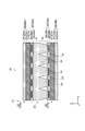
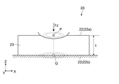
- FIG. 2 is a cross-sectional view of the sensor 20 as viewed from the side.
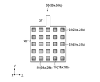
- FIG. 3 is a plan view showing the sensor electrode layer 30 in the sensor 20.
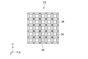
- FIG. 4 is a view of the separation layer 23 of the sensor 20 as viewed from the back side.
- the X-axis direction and the Y-axis direction are in-plane directions parallel to the sensing surface of the sensor 20, and the Z-axis direction is a vertical direction perpendicular to the sensing surface.
- the upper side corresponds to the front side to which an external force is applied
- the lower side corresponds to the back side on the opposite side.
- the sensor 20 has a rectangular flat plate shape as a whole in a plan view.
- the shape of the sensor 20 in a plan view may be appropriately set according to the shape of the portion where the sensor 20 is arranged, and the shape of the sensor 20 in a plan view is not particularly limited. ..
- the shape of the sensor 20 in a plan view may be a polygon other than a quadrangle, a circle, an ellipse, or the like.
- the sensor 20 is a separation layer 23 interposed between the sensor unit 21 including the first pressure sensor 22a on the front side and the second pressure sensor 22b on the back side, and the first pressure sensor 22a and the second pressure sensor 22b. And have. That is, the sensor 20 has a laminated structure in which the second pressure sensor 22b, the separation layer 23, and the first pressure sensor 22a are laminated in order from the lower layer side in the vertical direction. In the following description, when the two pressure sensors 22a and 22b are not particularly distinguished, they are simply referred to as the pressure sensor 22.
- a viscoelastic layer (not shown) having the same hardness as human skin is provided. This viscoelastic layer transmits an external force to the sensor 20 while being deformed in response to an external force.
- the sensor unit 21 is based on the in-plane pressure center position (pressure detection position) by the first pressure sensor 22a and the in-plane pressure center position (pressure detection position) by the second pressure sensor 22b.
- the force (shearing force Fs) applied in the in-plane direction to the sensor 20 is detected. Further, the sensor unit 21 detects a force (load Fz) applied from above in the direction perpendicular to the sensor 20 based on the pressure value detected by the first pressure sensor 22a.
- the sensor unit 21 is in the direction perpendicular to the sensor 20 based on two values, a pressure value detected by the first pressure sensor 22a and a pressure value detected by the second pressure sensor 22b.
- the force applied from above may be detected. That is, typically, the sensor unit 21 is from the upper side in the vertical direction based on the value of the pressure detected by at least the first pressure sensor 22a of the first pressure sensor 22a and the second pressure sensor 22b. It may be configured to detect the applied force.
- the first pressure sensor 22a and the second pressure sensor 22b are arranged so as to face each other in the vertical direction.
- the first pressure sensor 22a has a laminated structure in which the sensor electrode layer 30a, the deformed layer 27a, and the electrode film layer 26a are laminated in this order from the lower layer side in the vertical direction.
- the second pressure sensor 22b has a laminated structure in which the electrode film layer 26b, the deformed layer 27b, and the sensor electrode layer 30b are laminated in this order from the lower layer side in the vertical direction.
- the first pressure sensor 22a and the second pressure sensor 22b are arranged so as to be upside down. Therefore, both the first pressure sensor 22a and the second pressure sensor 22b are configured such that the sensor electrode layer 30 is arranged on the separation layer 23 side.
- the first pressure sensor 22a and the second pressure sensor 22b have basically the same configuration except that they are upside down.
- the first pressure sensor 22a and the second pressure sensor 22b may be arranged so that the top and bottom are the same.
- the sensor electrode layer 30 (see FIGS. 2 and 3) is made of a flexible printed circuit board or the like.
- the sensor electrode layer 30 has a rectangular main body 36 in a plan view and a drawer portion 37 extending outward from the main body 36.
- the pull-out unit 37 is provided to output the pressure information detected by the pressure sensor 22 to the control unit or the like.
- the shape of the sensor electrode layer in a plan view is not limited to a rectangle and can be changed as appropriate.
- the sensor electrode layer 30 has a flexible base material 29 and a plurality of sensing portions 28 provided inside the base material 29.
- a polymer resin such as polyethylene terephthalate, polycarbonate, or acrylic resin is used.
- the sensing units 28 are regularly arranged vertically and horizontally (vertical: Y-axis direction, horizontal: X-axis direction) at predetermined intervals.
- the number of sensing units 28 is 5 ⁇ 5 (vertical ⁇ horizontal), which is a total of 25.
- the number of sensing units 28 can be changed as appropriate.
- the sensing unit 28 is a capacitance type sensor capable of detecting a change in the distance between the electrode film layer 26 and the reference electrode layer 25 as a change in capacitance.
- the sensing unit 28 includes, for example, a comb-shaped pulse electrode (not shown) and a comb-shaped sense electrode.
- the comb-shaped pulse electrode and the comb-shaped sense electrode are arranged so that the comb teeth face each other and the other comb tooth is inserted between one comb tooth. ..
- the method of the sensing unit 28 is not particularly limited, and any method may be used.
- the electrode film layer 26 is flexible and has a film layer 24 and a reference electrode layer 25 provided on one surface side (the surface side of the deformed layer 27) of the film layer 24. ..
- the reference electrode layer 25 is a so-called ground electrode and has a ground potential.
- the thickness of the electrode film layer 26 is, for example, about 10 ⁇ m to 100 ⁇ m.
- the thickness of the reference electrode layer 25 is, for example, about 0.05 ⁇ m to 0.5 ⁇ m.
- the material of the film layer 24 for example, a polymer resin such as polyethylene terephthalate, polycarbonate, or acrylic resin is used.
- a polymer resin such as polyethylene terephthalate, polycarbonate, or acrylic resin is used.
- the inorganic conductive material examples include metals such as aluminum, copper and silver, alloys such as stainless steel, and metal oxides such as zinc oxide and indium oxide.
- the organic conductive material examples include carbon materials such as carbon black and carbon fiber, and conductive polymers such as substituted or unsubstituted polyaniline and polypyrrole. As the material, any material may be used as long as it is a conductive material.
- the reference electrode layer 25 is formed on the film layer 24 by, for example, a method such as thin film deposition, sputtering, adhesion, or coating.
- the film layer 24 may be omitted.
- the reference electrode layer 25 is made of a thin metal plate such as stainless steel or aluminum, a conductive fiber, or a conductive non-woven fabric.
- the deformable layer 27 is interposed between the sensor electrode layer 30 and the electrode film layer 26 (reference electrode layer 25).
- the thickness of the deformable layer 27 is, for example, about 50 ⁇ m to 300 ⁇ m.
- the deformable layer 27 is configured to be elastically deformable in response to an external force.
- an external force is applied in the direction perpendicular to the sensor 20, the deformation layer 27 elastically deforms in response to the external force, and the reference electrode layer 25 approaches the sensor electrode layer 30.
- the sensing unit 28 can detect the change in the capacitance as a pressure value.
- the thickness of the deformed layer 27 is larger than 100 ⁇ m and 1000 ⁇ m or less, and the basis weight of the deformed layer 27 is 50 mg / cm 2 or less. By setting the thickness and basis weight of the deformed layer 27 within this range, it is possible to improve the detection sensitivity of the pressure sensor 22 in the vertical direction.
- the lower limit of the thickness of the deformed layer 27 is not particularly limited as long as it is larger than 100 ⁇ m, but the lower limit may be, for example, 150 ⁇ m or more, 200 ⁇ m or more, 250 ⁇ m or more, 300 ⁇ m or more, and the like.
- the upper limit of the thickness of the deformed layer 27 is not particularly limited as long as it is 1000 ⁇ m or less, but the upper limit may be, for example, 950 ⁇ m or more, 900 ⁇ m or less, 850 ⁇ m or less, 800 or less.
- the thickness of the deformed layer 27 is obtained as follows. First, the pressure sensor 22 is processed by the IB (Focused Ion Beam) method or the like to prepare a cross section, and a scanning electron microscope (SEM) is used to obtain a cross section image (hereinafter referred to as "cross section SEM image"). Be photographed. Next, points are randomly selected from the deformed layer 27 in this cross-sectional SEM image, and the thickness of the deformed layer 27 is measured at the points.
- IB Flucused Ion Beam
- SEM scanning electron microscope
- the upper limit of the basis weight of the deformed layer 27 is not particularly limited as long as it is 50 mg / cm 2 or less, but the upper limit is, for example, 45 mg / cm 2 or less, 40 mg / cm 2 or less, 35 mg / cm 2 or less, and the like. May be done.
- the lower limit of the basis weight of the deformed layer 27 is not particularly limited, but the lower limit is, for example, 3 mg / cm 2 or more, 5 mg / cm 2 or more, 7 mg / cm 2 or more, 10 mg / cm 2 or more, and the like. May be good.
- the deformed layer 27 includes a porous layer.
- the porous layer may be a fiber layer.
- the fiber layer is, for example, a non-woven fabric or a woven fabric.
- the fiber contained in the fiber layer may be a nanofiber or a thicker fiber.
- the sensitivity of the pressure sensor 22 in the vertical direction can be further improved.
- the fiber may contain a polymer resin or may contain an inorganic material. When the fiber contains a polymer resin, the sensitivity of the pressure sensor 22 in the vertical direction can be further improved.
- the porous layer includes a three-dimensional three-dimensional structure (irregular network structure such as a non-woven fabric) formed by a fibrous structure, and may be provided with a plurality of gaps (pores). Since the porous layer contains a three-dimensional three-dimensional structure, a structure having a large porosity can be produced, and thinning is easy.
- a three-dimensional three-dimensional structure such as a non-woven fabric
- the fibrous structure is a fibrous substance having a sufficient length with respect to the fiber diameter (diameter). For example, a plurality of fibrous structures are assembled and randomly overlapped to form a porous layer. One fibrous structure may be randomly entangled to form a porous layer. Alternatively, a porous layer made of one fibrous structure and a porous layer made of a plurality of fibrous structures may be mixed.
- the fibrous structure extends linearly, for example.
- the fibrous structure may have any shape, for example, it may be crimped or bent in the middle. Alternatively, the fibrous structure may be branched in the middle.
- the minimum fiber diameter of the fibrous structure is, for example, 500 nm or less, 300 nm or less, and the like.
- the average fiber diameter is, for example, 0.1 ⁇ m or more and 10 ⁇ m or less. By reducing the average fiber diameter, the pore diameter of the pores increases.
- the average fiber diameter can be measured by, for example, microscopic observation using a scanning electron microscope or the like.
- the average length of the fibrous structure is arbitrary.
- the fibrous structure is formed by, for example, a phase separation method, a phase inversion method, an electrostatic (electric field) spinning method, a melt spinning method, a wet spinning method, a dry spinning method, a gel spinning method, a sol-gel method, a spray coating method, or the like. NS. By using such a method, a fibrous structure having a sufficient length with respect to the fiber diameter can be easily and stably formed.
- the fibrous structure is formed of at least one of a polymer material and an inorganic material, and is particularly composed of nanofibers.
- the nanofiber is a fibrous substance having a fiber diameter of 1 nm or more and 1000 nm or less and a length of 100 times or more of the fiber diameter.
- the fibrous structure made of nanofibers may be formed by an electrostatic spinning method. By using the electrostatic spinning method, a fibrous structure having a small fiber diameter can be easily and stably formed.
- the deformable layer 27 may be composed of, for example, a patterning structure including a pillar structure.
- a patterning structure including a pillar structure.
- various structures such as a matrix shape, a stripe shape, a mesh shape, a radial shape, a geometric shape shape, and a spiral shape can be adopted.
- Separatation layer 23 The separation layer 23 is fixed between the first pressure sensor 22a and the second pressure sensor 22b via an adhesive layer (not shown).
- the separation layer 23 is deformable in response to an external force.
- the separation layer 23 has a gap 33, and has a plurality of vertically extending pillars 34 formed by the gap 33.
- the gap 33 is provided in a groove shape on the back surface side (second pressure sensor 22b side) of the separation layer 23 so as not to penetrate the separation layer 23 in the vertical direction.
- the separation layer 23 has a filling layer 31 (first layer) having a filling structure having no gap 33 on the front side (first pressure sensor 22a side). Further, the separation layer 23 has a pillar layer 32 (second layer) having a gap 33 and having a plurality of pillars 34 formed by the gap 33 on the back side (second pressure sensor 22b side). Have in.
- Each of the plurality of pillar portions 34 has a shape in which the thickness is not constant in the vertical direction and the thickness is different.
- the thickness of the plurality of pillar portions 34 gradually decreases from the front side (first pressure sensor 22a side) to the back side (second pressure sensor 22b side) in the vertical direction. It is formed like this.
- each of the plurality of pillars 34 has an inverted quadrangular frustum shape.
- the pillar portion 34 may be formed in a shape such as an inverted truncated cone, an inverted triangular pyramid, an inverted pentagonal pyramid, an inverted hexagonal pyramid, and the like.
- the pillars 34 are regularly arranged vertically and horizontally. Each of the pillar portions 34 is provided at a position corresponding to the sensing portion 28 in the vertical direction, and therefore, the gap portion 33 for forming the pillar portion 34 is provided at a position not corresponding to the sensing portion 28 in the vertical direction. Has been done.
- the number of pillar portions 34 is the same as the number of sensing portions 28b in the second pressure sensor 22b, and the total number is 5 ⁇ 5 (length ⁇ width). The number of pillars 34 can be changed as appropriate.
- the thickness of the separation layer 23 is, for example, about 1000 ⁇ m to 5000 ⁇ m.
- the vertical height of the column portion 34 (that is, the depth of the groove-shaped gap portion 33) is 20% or more, 25% or more, 30% or more, 35% or more, 40% or more of the thickness of the separation layer 23. , 45% or more.
- the height of the pillar portion 34 may be high (for example, 100% of the thickness of the separation layer 23), but if it is too low (for example, less than 20% of the thickness of the separation layer 23), the pillar portion may be high. There is a possibility that 34 will not function effectively.
- the area (in-plane direction) of the lower surface of the pillar portion 34 (the portion that contacts the second pressure sensor 22b) is set according to the area of the sensing portion 28b of the second pressure sensor 22, for example, the sensing portion.
- the area is about the same as the area of 28b.
- the separation layer 23 is typically made of a viscoelastic material having viscoelastic properties.
- examples of the material used for the separation layer 23 include silicon gel, urethane gel, synthetic rubber, and foam.
- FIG. 5 is a diagram showing each example in the shape of the separation layer 23.
- FIG. 5 shows six patterns of shapes A to F for the shape of the separation layer 23.
- the first pressure sensor 22a and the second pressure sensor 22b are simplified and illustrated.
- Shape A The shape A is the shape already described in FIGS. 2 and 4.
- the gap portion 33 is provided in a groove shape on the back surface side (second pressure sensor 22b side) of the separation layer 23 so as not to penetrate the separation layer 23 in the vertical direction.
- the shape B has a two-layer structure of a filling layer 31 and a pillar layer 32, similarly to the shape A.
- the thickness of the pillar portion 34 is different in the vertical direction, but in the shape B, the thickness of the pillar portion 34 is the same in the vertical direction.
- the shape of the pillar portion 34 has a square columnar shape.
- the shape of the pillar portion 34 may be formed into a columnar shape, a triangular columnar shape, a pentagonal columnar shape, a hexagonal columnar shape, and the like.
- the pillar portion 34 in the shape B is typically provided at a position corresponding to the sensing portion 28b in the second pressure sensor 22b in the vertical direction, similarly to the pillar portion 34 in the shape A.
- the gap 33 has a groove shape that does not penetrate the separation layer 23 in the vertical direction, but in the shape C, the gap 33 has a hole shape that penetrates the separation layer 23 in the vertical direction. ing.
- the height of the pillar portion 34 is higher than that of the shapes A and B, and the height of the pillar portion 34 coincides with the thickness of the separation layer 23. That is, the height of the pillar portion 34 is set to 100% with respect to the thickness of the separation layer 23.
- the separation layer 23 has a two-layer structure of the filling layer 31 and the pillar layer 32, but in the shape C, the filling layer 31 does not exist, and the separation layer 23 is the pillar layer. It has a one-layer structure of 32.
- the shape of the pillar portion 34 is an inverted quadrangular pyramid, but the shape of the pillar portion 34 is an inverted cone, an inverted triangular pyramid, an inverted pentagonal pyramid, an inverted hexagonal pyramid, or an inverted hexagonal pyramid. ⁇ ⁇ It may be.
- the gap portion 33 has a hole shape that penetrates the separation layer 23 in the vertical direction. Further, in the shape D, as in the shape C, the height of the pillar portion 34 coincides with the thickness of the separation layer 23, and the height of the pillar portion 34 is 100% with respect to the thickness of the separation layer 23. Has been done.
- the thickness of the pillar portion 34 is different in the vertical direction, but in the shape D, the thickness of the pillar portion 34 is the same in the vertical direction.
- the shape of the pillar portion 34 has a square columnar shape.
- the shape of the pillar portion 34 may be formed into a columnar shape, a triangular columnar shape, a pentagonal columnar shape, a hexagonal columnar shape, and the like.
- Shape E shows an example of a combination of shapes A to D and the like. That is, the shapes A to D and the like can be combined as appropriate.
- the leftmost pillar portion 34 corresponds to the pillar portion 34 of the shape C.
- the other four pillars 34 correspond to the pillars 34 in the shape D, but each has a different thickness.
- a circular gap portion 33 (a gap portion 33 that does not contact either the first pressure sensor 22a or the second pressure sensor 22b) is provided at the center position in the vertical direction. Have.
- the shape F is a comparative example having no gap 33, and the separation layer 23'has a structure in which the entire separation layer 23'is completely filled.
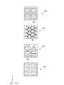
- FIG. 6 is a view of the separation layer 23 viewed from the back surface side, and is a view showing each pattern of the shape of the pillar portion 34 in a plan view.
- the uppermost figure of FIG. 6 shows a state when the pillar portion 34 is made into a square pillar.
- the second figure from the top of FIG. 6 shows a state when the pillar portion 34 has a hexagonal columnar shape (honeycomb structure).
- the third figure from the top of FIG. 6 shows a state when pillar portions 34 having different shapes (cylinder, quadrangular prism, triangular prism, etc.) are combined.
- the bottom figure in FIG. 6 corresponds to a comparative example having no gap 33.
- FIG. 7 is a diagram showing a state when a load Fz is applied downward in the vertical direction with respect to the sensor 20 as a model.
- FIG. 8 is a diagram showing a state when a shearing force Fs is applied in the in-plane direction to the sensor 20 in a state where a load Fz in the vertical direction is applied as a model.
- the contour line of the detected pressure is shown by a broken line circle.
- the pressure center position means a position in the in-plane direction corresponding to the highest pressure in the detected pressure distribution.
- the separation layer 23 is distorted according to the shear force Fs applied in the in-plane direction, and at this time, the separation layer 23 generates a shear stress ⁇ corresponding to the shear force Fs.
- the rigidity of the separation layer 23 is G
- the thickness of the separation layer 23 is t.
- the shear stress ⁇ (shear force Fs) is expressed by the following equation.
- the rigidity G of the separation layer 23 is known on the right side of the equation. Therefore, if the difference d between the pressure center position P in the in-plane direction of the first pressure sensor 22a and the pressure center position Q in the in-plane direction of the second pressure sensor 22b is obtained, shearing The stress Fs, that is, the in-plane force can be detected.
- FIG. 9 is a diagram showing an evaluation of variation in the detection sensitivity of the shear force Fs in the separation layer 23'according to the comparative example.
- the upper view of FIG. 9 is a top view showing the sensor 20 according to the comparative example, and shows the points and directions in the in-plane direction to which the shear force Fs is applied.
- the central figure of FIG. 9 is a side view showing the sensor 20 according to the comparative example.
- the separation layer 23' accordinging to the comparative example does not have the gap 33, and the entire structure is filled. Further, as shown in the upper figure of FIG. 9, in this evaluation test, in the in-plane direction of the sensor 20, the points A near the upper left corner, the point B near the lower left corner, and the point C in the center are separated. At the timing of, a vertical load Fz was applied and a shear force Fs was applied in the X-axis direction.
- the lower figure of FIG. 9 is a view when the shear force Fs is changed at points A, B, and C, and the difference d between the pressure center position P and the pressure center position Q is measured.
- the difference d at point C near the center was smaller than at points A and B near the corner.
- the shear force Fs is calculated at the points A, B, and C based on the difference d.
- the shearing force Fs obtained at the point C becomes smaller than the shearing force Fs obtained at the points A and B.
- the detection sensitivity of the shearing force Fs at each point in the in-plane direction is different.
- the shear stress ⁇ with respect to the shear force Fs is smaller in the separation layer 23'as compared with the vicinity of the center in the in-plane direction, and the separation layer 23'is more likely to be distorted with respect to the shear force Fs.
- the slope of the graph indicates the detection sensitivity of the shear force Fs at each point. That is, the larger the inclination, the better the detection sensitivity of the shear force Fs, and the smaller the inclination, the worse the detection sensitivity of the shear force Fs.
- the detection sensitivity of shear force Fs is worse than at points A and B near the corner. Further, at points A and B near the corners, the detection sensitivity of the shear force Fs is relatively higher than that at the point C near the center, but this detection sensitivity is insufficient as the detection sensitivity of the shear force Fs. Is. That is, in the comparative example, the detection sensitivity of the shearing force Fs itself is poor in the first place.
- the pressure detection sensitivity of the second pressure sensor 22b is poor because the separation layer 23'is a structure that is completely filled. That is, in the case of the comparative example, the separation layer 23'is completely filled up, so that when a vertical load Fz is applied, the entire separation layer 23'becomes a buffer layer, and the second pressure sensor The force is hard to be transmitted to 22b. Therefore, the position of the pressure center position Q detected by the second pressure sensor 22b becomes inaccurate, and the shear force Fs may not be measured accurately.
- the gap portion 33 is formed in the separation layer 23, and the separation layer 23 has a predetermined shape (for example, a shape having a pillar portion 34).
- FIG. 10 is a diagram showing an evaluation of variations in the detection sensitivities of shear forces Fs in the separation layer 23 according to the present embodiment.
- the upper view of FIG. 10 is a top view showing the sensor 20 according to the present embodiment, and shows the points and directions in the in-plane direction to which the shear force Fs is applied.
- the central figure of FIG. 10 is a side view showing the sensor 20 according to the present embodiment.
- the above-mentioned separation layer 23 having a shape B was used as the separation layer 23 according to the present embodiment.
- the separation layer 23 of shape B has a two-layer structure in which the front side is filled with the layer 31 and the back side is a pillar layer 32 by the groove-shaped gap 33. Further, the pillar portion 34 in the pillar layer 32 has a square columnar shape.
- the lower figure of FIG. 10 is a view when the shear force Fs is changed at points A, B, and C, and the difference d between the pressure center position P and the pressure center position Q is measured.
- the slope of the graph at each point in the present embodiment is higher than the slope of the graph at each point according to the comparative example. Is also big. This means that in the present embodiment, the detection sensitivity of the shearing force Fs is larger than that of the comparative example.
- the reason why the detection sensitivity of the shear force Fs is uniform in the in-plane direction and the detection sensitivity of the shear force Fs is improved is that the gap 33 is provided in the separation layer 23. That is, in the present embodiment, since the gap 33 is provided in the separation layer 23, the easiness of distortion (shear stress ⁇ ) of the separation layer 23 with respect to the shear force Fs at each point in the in-plane direction is uniform. Therefore, in the present embodiment, the detection sensitivity of the shear force Fs is uniform in the in-plane direction.
- the separation layer 23 corresponds to the point in the in-plane direction where the shearing force Fs is generated. Is locally distorted, and distortion is not transmitted so much to parts other than the local area. Its local strainability (shear stress ⁇ ) is uniform regardless of the point in the in-plane direction. Therefore, in the present embodiment, the detection sensitivity of the shear force Fs becomes uniform in the in-plane direction.
- the separation layer 23 is easily distorted with respect to the shear force Fs at each point in the in-plane direction (shear stress ⁇ is reduced). ) Therefore, the detection sensitivity of the shearing force Fs is improved.
- the pillar portion 34 formed by the gap portion 33 is provided at a position corresponding to the sensing portion 28 of the second pressure sensor 22b. Therefore, when a load Fz in the vertical direction is applied to the sensor 20, the pillar portion 34 locally pushes the portion corresponding to the sensing portion 28 in the second pressure sensor 22b, so that the second pressure sensor 22b The force can be transmitted efficiently in. Therefore, even if the load Fz in the vertical direction is small, the pressure center position Q can be accurately detected by the second pressure sensor 22b, and the shear force Fs can be accurately measured.
- the pillar layer 32 is made of a material that is relatively harder than the filling layer 31. It may be configured. In this case, when a load Fz in the direction perpendicular to the sensor 20 is applied, the column portion 34 in the relatively hard column layer 32 locally pushes the portion corresponding to the sensing portion 28 in the second pressure sensor 22b. Therefore, the force can be transmitted more efficiently in the second pressure sensor 22b.
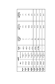
- FIG. 11 is a diagram showing each example and each comparative example in the separation layer 23.
- sensors 20 including separation layers 23 having different thicknesses and shapes are prepared, and for each sensor 20, the detection sensitivity of the shear force Fs in the in-plane direction and the surface of the shear force Fs The variation in the detection sensitivity in the inward direction and the resolution of the detection sensitivity in the in-plane direction of the shear force Fs were evaluated.
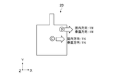
- FIG. 12 is a diagram showing a state when the variation in the detection sensitivity of the shear force Fs and the detection sensitivity of the shear force Fs is evaluated.
- the detection sensitivity of the shearing force Fs in-plane with a load Fz of 1N applied downward in the vertical direction with respect to the central C point by the keystroker of ⁇ 6 in the evaluation device.
- the detection sensitivity (S / N) of the shearing force Fs was measured. That is, the detection sensitivity of the shearing force Fs at the central point C is typically the detection sensitivity of the sensor 20.
- a load Fz of 1N is applied to the lower side in the vertical direction with respect to the D point near the right corner by the keystroker of ⁇ 6 in the evaluation device.
- the detection sensitivity (S / N) of the shearing force Fs was measured by applying a shearing force Fs of 1N in the in-plane direction.
- the ratio of the detection sensitivity at the D point ((the detection sensitivity at the D point / the detection sensitivity at the C point) ⁇ 100) based on the detection sensitivity at the central C point is obtained, and this ratio is the shearing force. It was used as the evaluation value of the variation of Fs in the in-plane direction.
- the evaluation value of variation when it is close to 100%, there is no variation and the detection sensitivity in the in-plane direction is uniform.
- FIG. 13 is a diagram showing a state when the resolution of the detection sensitivity of the shear force Fs in the in-plane direction is evaluated.
- a load Fz of 1N is applied downward in the vertical direction at the same time at the central point C and the point D near the right corner by the keystroker of ⁇ 6 in the evaluation device.
- a shear force Fs of 1N is applied in the in-plane direction only to the central point C.
- the ratio of the detection sensitivity of the shear force Fs at the D point (the detection sensitivity of the D point / the detection sensitivity of the C point) ⁇ 100) is obtained based on the detection sensitivity of the shear force Fs at the central C point. , This ratio was used as the evaluation value of the resolution in the in-plane direction.
- the shearing force Fs is detected only at the point C, and the shearing force Fs is detected only at the point D.
- no shear force Fs is detected, which is the highest resolution. Therefore, the resolution is higher when the evaluation value of the resolution is closer to 0%.
- the resolution of the detection sensitivity of the shear force Fs in the in-plane direction means that when it is necessary to detect the shear force Fs at two or more points, the shear force Fs is sheared at a certain point. When a force Fs is applied, it is an index of whether or not the shear force Fs can be appropriately detected only at that point without affecting other peripheral points.
- Example 1 In Example 1, the thickness of the separation layer 23 was 2000 ⁇ m, and as the material of the separation layer 23, a silicon gel having a hardness of 100 ° needle insertion was used. Further, in Example 1, the separation layer 23 of the shape D (see FIG. 5) was used, and the separation layer 23 in which the pillars 34 were arranged in 3 ⁇ 3 in the vertical and horizontal directions was used. As for the material of the separation layer 23, the same material is used in each Example and each Comparative Example (silicon gel having a hardness of 100 ° needle insertion degree).
- Example 1 the detection sensitivity of the shear force Fs was 4.5, and the variation of the detection sensitivity of the shear force Fs in the in-plane direction was 130%. Further, in Example 1, the resolution of the detection sensitivity of the shear force Fs in the in-plane direction was 50%.
- Example 2 In Example 2, the thickness of the separation layer 23 was set to 4000 ⁇ m. Further, in Example 2, the separation layer 23 of the shape D (see FIG. 5) was used, and the separation layer 23 in which the pillars 34 were arranged in 3 ⁇ 3 in the vertical and horizontal directions was used.
- Example 2 the detection sensitivity of the shear force Fs was 7.5, and the variation of the detection sensitivity of the shear force Fs in the in-plane direction was 130%. Further, in Example 2, the resolution of the detection sensitivity of the shear force Fs in the in-plane direction was 50%.
- Example 2 comparing Example 1 and Example 2, they have the same material and shape of the separation layer 23, but the thickness of the separation layer 23 is different. In Example 2, since the thickness of the separation layer 23 is thicker than that of Example 1, the detection sensitivity of the shear force Fs is higher than that of Example 1.
- Example 3 In Example 3, the thickness of the separation layer 23 was set to 4000 ⁇ m. Further, in Example 3, the separation layer 23 of the shape C (see FIG. 5) was used, and the separation layer 23 in which the pillars 34 were arranged in 3 ⁇ 3 in the vertical and horizontal directions was used.
- Example 3 the detection sensitivity of the shear force Fs was 7.5, and the variation of the detection sensitivity of the shear force Fs in the in-plane direction was 130%. Further, in Example 3, the resolution of the detection sensitivity of the shear force Fs in the in-plane direction was 50%.
- Example 4 In Example 4, the thickness of the separation layer 23 was set to 4000 ⁇ m. Further, in Example 4, the separation layer 23 of the shape B (see FIG. 5) was used, and the separation layer 23 in which the pillars 34 were arranged in 3 ⁇ 3 in the vertical and horizontal directions was used.
- Example 4 the detection sensitivity of the shear force Fs was 10.0, and the variation of the detection sensitivity of the shear force Fs in the in-plane direction was 100%. Further, in Example 4, the resolution of the detection sensitivity of the shear force Fs in the in-plane direction was 25%.
- Example 4 when Example 4 is compared with Examples 2 and 3, they have the same thickness and material of the separation layer 23, and the shapes of the separation layer 23 are different (shape B, and the shape B, and the shape B). , Shape D and Shape C).
- the detection sensitivity, variation, and resolution of the shearing force Fs are improved as compared with Examples 2 and 3. Therefore, it can be seen that the separation layer 23 of shape B has higher performance than the separation layer 23 of shapes D and C.
- the separation layer 23 of the shape B is improved as compared with the separation layer 23 of the shape D and the shape C.
- the separation layer 23 includes the layer 31 and the pillar layer 32. This is because it has a layered structure. That is, in the shape B, the filling layer 31 sufficiently supports the first pressure sensor 22a from below, so that the first pressure sensor 22a can appropriately detect the pressure due to the external force (pressure center position). In addition to this, in the shape B, since the pillar portion 34 by the pillar layer 32 locally pushes the second pressure sensor 22b, the second pressure sensor 22b appropriately detects the pressure due to the external force (pressure center position). Can be done.
- Example 5 In Example 5, the thickness of the separation layer 23 was set to 4000 ⁇ m. Further, in Example 5, the separation layer 23 of the shape A (see FIG. 5) was used, and the separation layer 23 in which the pillars 34 were arranged in 3 ⁇ 3 in the vertical and horizontal directions was used.
- Example 5 the detection sensitivity of the shear force Fs was 10.0, and the variation of the detection sensitivity of the shear force Fs in the in-plane direction was 100%. Further, in Example 5, the resolution of the detection sensitivity of the shear force Fs in the in-plane direction was 25%.
- Examples 4 and 5 comparing Examples 4 and 5, they have the same thickness and material of the separation layer 23, but different shapes of the separation layer 23 (shape B, shape A).
- the detection sensitivity, variation, and resolution of the shear force Fs have the same values. Therefore, it can be seen that the separation layer 23 of the shape B and the shape A has substantially the same performance.
- Both the shape B and the shape A have a two-layer structure including a layer 31 and a pillar layer 32 filled with the separation layer 23.
- Example 6 In Example 6, the thickness of the separation layer 23 was set to 4000 ⁇ m. Further, in Example 6, the separation layer 23 of the shape A (see FIG. 5) was used, and the separation layer 23 in which the column portions 34 were arranged in a vertical and horizontal direction of 9 ⁇ 9 was used.
- Example 6 the detection sensitivity of the shear force Fs was 10.0, and the variation of the detection sensitivity of the shear force Fs in the in-plane direction was 100%. Further, in Example 6, the resolution of the detection sensitivity of the shear force Fs in the in-plane direction was 10%.
- Example 5 and Example 6 when Example 5 and Example 6 are compared, they have the same thickness, material, and shape of the separation layer 23, and differ in the fineness of the gap portion in the separation layer 23 (of the separation layer 23). The number of divisions is different).
- Example 6 the resolution of the shearing force Fs is improved as compared with Example 5. This is because, in Example 6, the gap 33 is finely arranged in the separation layer 23 as compared with Example 5, so that the shearing force Fs at a certain point is more difficult to be transmitted to the surrounding points. Is.
- Comparative Example 1 In Comparative Example 1, the thickness of the separation layer 23 was 2000 ⁇ m. Further, in Comparative Example 1, a separation layer 23'of the shape F (see FIG. 5), that is, a separation layer 23' having a completely filled structure was used.
- Comparative Example 1 the detection sensitivity of the shear force Fs was 3.0, and the variation of the detection sensitivity of the shear force Fs in the in-plane direction was 240%. Further, in Comparative Example 1, the resolution of the detection sensitivity of the shear force Fs in the in-plane direction was 100%.
- Comparative Example 2 In Comparative Example 2, the thickness of the separation layer 23 was set to 4000 ⁇ m. Further, in Comparative Example 2, a separation layer 23'of the shape F (see FIG. 5), that is, a separation layer 23' having a completely filled structure was used.
- the detection sensitivity of the shear force Fs was 5.0, and the variation of the detection sensitivity of the shear force Fs in the in-plane direction was 200%. Further, in Comparative Example 2, the resolution of the detection sensitivity of the shear force Fs in the in-plane direction was 80%.
- Comparative Example 1 and Comparative Example 2 when compared, they have the same material and shape of the separation layer 23, but the thickness of the separation layer 23 is different.
- Comparative Example 2 since the thickness of the separation layer 23 is thicker than that of Comparative Example 1, the detection sensitivity, variation, and resolution of the shear force Fs are improved as compared with Comparative Example 1, but the performance is not good. It is enough.
- the reason why the resolution of the shearing force Fs in the in-plane direction is improved is that the gap 33 is provided in the separation layer 23. That is, when the shear force Fs is applied to the sensor 20, the gap 33 is provided in the separation layer 23, so that the separation layer 23 is locally located at the point corresponding to the point in the in-plane direction where the shear force Fs is generated. Distortion, and distortion is not transmitted so much to parts other than the local area. Therefore, the resolution is improved.
- the first pressure sensor 22a and the second pressure sensor 22b have a sensor electrode layer 30, a deformed layer 27, and an electrode film layer 26 (reference electrode layer 25). It has a laminated three-layer structure.
- the deformation layer 27 is made thinner and the deformation layer 27 is made softer to improve the detection sensitivity to the load Fz in the vertical direction.
- the thickness of the deformed layer 27 is larger than 100 ⁇ m and 1000 ⁇ m or less, and the basis weight in the deformed layer 27 is 50 mg / cm 2 or less.
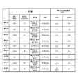
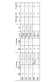
- FIG. 14 is a diagram showing each example and each comparative example in the deformed layer 27 (see FIG. 2).
- FIG. 14 shows the thickness, basis weight, trade name, and material of the deformed layer 27 in each Example and Comparative Example. Further, FIG. 14 shows the detection sensitivity (S / N) in the vertical direction of the sensor 20 when a load Fz of 1 kPa or 100 kPa is applied downward in the vertical direction with respect to the sensor 20. There is.
- the load Fz in the vertical direction with respect to the sensor 20 is obtained based on the value of the pressure detected by the first pressure sensor 22a. Therefore, the detection sensitivity of the sensor 20 in the vertical direction is determined. , The vertical detection sensitivity of the first pressure sensor 22a is used for evaluation.
- FIG. 15 is a diagram showing the relationship between the thickness of the deformed layer 27 and the basis weight amount in each Example and each Comparative Example.
- Example 7 In Example 7, the thickness of the deformed layer 27 was set to 300 ⁇ m, and the basis weight was set to 7.2 mg / cm 2 . Further, in Example 7, PORON (registered trademark) SS-24DP, which is a foamed film made of polyurethane, was used as the material of the deformable layer 27.
- Example 7 the detection sensitivities of the sensor 20 in the vertical direction when a load Fz of 1 kPa and 100 kPa were applied in the vertical direction to the sensor 20 were 3.0 and 80, respectively. This detection sensitivity is considered to be a high value at low pressure and high pressure.
- Example 8 In Example 8, the thickness of the deformed layer 27 was set to 500 ⁇ m, and the basis weight was set to 12 mg / cm 2 . Further, in Example 8, PORON (registered trademark) SS-24DP, which is a foamed film made of polyurethane, was used as the material of the deformable layer 27.
- Example 8 the detection sensitivities of the sensor 20 in the vertical direction when a load Fz of 1 kPa and 100 kPa were applied in the vertical direction to the sensor 20 were 2.5 and 120, respectively. This detection sensitivity is considered to be a high value at low pressure and high pressure.
- Example 9 In Example 9, the thickness of the deformed layer 27 was 1000 ⁇ m, and the basis weight was 24 mg / cm 2 . Further, in Example 9, PORON (registered trademark) SS-24DP, which is a foamed film made of polyurethane, was used as the material of the deformable layer 27.
- Example 9 the detection sensitivities of the sensor 20 in the vertical direction when a load Fz of 1 kPa and 100 kPa were applied in the vertical direction to the sensor 20 were 2.0 and 150, respectively. This detection sensitivity is considered to be a high value at low pressure and high pressure.
- Example 10 In Example 10, the thickness of the deformed layer 27 was 150 ⁇ m, and the basis weight was 4 mg / cm 2 . Further, in Example 10, PORON (registered trademark) SS-15DP, which is a foamed film made of polyurethane, was used as the material of the deformable layer 27.
- Example 10 the detection sensitivities of the sensor 20 in the vertical direction when the loads Fz of 1 kPa and 100 kPa were applied in the vertical direction to the sensor 20 were 4.0 and 200, respectively. This detection sensitivity is considered to be a high value at low pressure and high pressure.
- Example 11 In Example 11, the thickness of the deformed layer 27 was set to 500 ⁇ m, and the basis weight was set to 7.5 mg / cm 2 . Further, in Example 11, nanofibers made of polyurethane were used as the material of the deformable layer 27.
- Example 11 the detection sensitivities of the sensor 20 in the vertical direction when a load Fz of 1 kPa and 100 kPa were applied in the vertical direction to the sensor 20 were 2.0 and 60, respectively. This detection sensitivity is considered to be a high value at low pressure and high pressure.
- Example 12 In Example 12, the thickness of the deformed layer 27 was 1000 ⁇ m, and the basis weight was 48 mg / cm 2 . Further, in Example 12, PORON (registered trademark) SR-S-48, which is a foamed film made of polyurethane, was used as the material of the deformable layer 27.
- Example 12 the detection sensitivities of the sensor 20 in the vertical direction when a load Fz of 1 kPa and 100 kPa were applied in the vertical direction to the sensor 20 were 1.5 and 80, respectively. This detection sensitivity is considered to be a high value at low pressure and high pressure.
- Comparative Example 3 In Comparative Example 3, the thickness of the deformed layer 27 was 100 ⁇ m, and the basis weight was 3 mg / cm 2 . Further, in Example 3, Purecell (registered trademark) S010, which is a foamed film made of polyurethane, was used as the material of the deformable layer 27.
- the detection sensitivities of the sensor 20 in the vertical direction when a load Fz of 1 kPa and 100 kPa were applied in the vertical direction to the sensor 20 were 2.0 and 20, respectively.
- Comparative Example 3 the detection sensitivity when a load Fz of 1 kPa is applied is not a problem, but the detection sensitivity when a load Fz of 100 kPa is applied is too low. That is, in Comparative Example 3, since the thickness of the deformed layer 27 is 100 ⁇ m, which is too thin, the amount of deformation at high pressure is small and the detection sensitivity is poor. Therefore, in the present embodiment, the thickness of the deformed layer 27 is typically larger than 100 ⁇ m (see also that good results are obtained with a thickness of 150 ⁇ m in Example 10).
- Comparative Example 4 In Comparative Example 4, the thickness of the deformed layer 27 was 1000 ⁇ m, and the basis weight was 60 mg / cm 2 . Further, in Example 4, PORON (registered trademark) NU60, which is a foamed film made of polyurethane, was used as the material of the deformable layer 27.
- the detection sensitivities of the sensor 20 in the vertical direction when a load Fz of 1 kPa and 100 kPa were applied in the vertical direction to the sensor 20 were 1 or less and 30, respectively.
- both the detection sensitivity when a load Fz of 1 kPa is applied and the detection sensitivity when a load Fz of 100 kPa is applied are too low.
- the basis weight is 60 mg / cm 2 , and the basis weight is too high, so that the deformed layer 27 is too hard. Therefore, in the present embodiment, the basis weight of the deformed layer 27 is typically 50 mg / cm 2 or less (good results can be obtained with the basis weight of 48 mg / cm 2 in Example 12). reference).
- Comparative Example 5 In Comparative Example 5, the thickness of the deformed layer 27 was 1200 ⁇ m, and the basis weight was 48 mg / cm 2 . Further, in Example 5, PORON (registered trademark) MS40, which is a foamed film made of polyurethane, was used as the material of the deformable layer 27.
- the detection sensitivities of the sensor 20 in the vertical direction when a load Fz of 1 kPa and 100 kPa were applied in the vertical direction to the sensor 20 were 1 or less and 80, respectively.
- the detection sensitivity when a load Fz of 100 kPa is applied is not a problem, but the detection sensitivity when a load Fz of 1 kPa is applied is too low. That is, in Comparative Example 5, since the thickness of the deformed layer 27 is 1200 ⁇ m, which is too thick, the distance between the sensor electrode layer 30 and the reference electrode layer 25 is too long for the amount of deformation at low pressure, and the detection sensitivity is poor. Therefore, in the present embodiment, the thickness of the deformed layer 27 is typically 1000 ⁇ m or less (see also that good results are obtained with a thickness of 1000 ⁇ m in Examples 9 and 12). ..
- the thickness of the deformed layer 27 is larger than 100 ⁇ m and 1000 ⁇ m or less, and the basis weight in the deformed layer 27 is 50 mg / cm 2 or less, the load Fz in the vertical direction is applied. It can be seen that the detection sensitivity can be improved.
- the gap 33 is provided in the separation layer 23.
- the detection sensitivity of the shear force Fs becomes uniform in the in-plane direction, the detection sensitivity of the shear force Fs is improved, and the resolution of the shear force Fs in the in-plane direction is improved.
- the separation layer 23 since the gap 33 is provided in the separation layer 23, when the shear force Fs is applied, the separation layer 23 is located at a position corresponding to the point in the in-plane direction where the shear force Fs is generated. It is locally distorted, and the distortion is not transmitted so much to the parts other than the local area. Its local strainability (shear stress ⁇ ) is uniform regardless of the point in the in-plane direction. Therefore, in the present embodiment, the detection sensitivity of the shear force Fs becomes uniform in the in-plane direction. Further, in the present embodiment, the resolution is also improved due to the characteristic that the separation layer 23 is locally distorted at the point corresponding to the point in the in-plane direction to which the shearing force Fs is applied.
- the separation layer 23 is easily distorted with respect to the shear force Fs at each point in the in-plane direction (shear stress ⁇ becomes small). This makes it possible to improve the detection sensitivity of the shear force Fs.
- the pillar portion 34 formed by the gap portion 33 is provided at a position corresponding to the sensing portion 28 of the second pressure sensor 22b. Therefore, when a load Fz in the vertical direction is applied to the sensor 20, the pillar portion 34 locally pushes the portion corresponding to the sensing portion 28 in the second pressure sensor 22b, so that the second pressure sensor 22b The force can be transmitted efficiently in. Therefore, even if the load Fz in the vertical direction is small, the pressure center position Q can be accurately detected by the second pressure sensor 22b, and the shear force Fs can be accurately measured.
- the filling layer 31 sufficiently supports the first pressure sensor 22a from below.
- the first pressure sensor 22a can appropriately detect the pressure due to the external force (pressure center position).
- the pillar portion 34 formed by the pillar layer 32 locally pushes the second pressure sensor 22b, so that the second pressure sensor 22b appropriately applies the pressure (pressure center position) due to the external force. Can be detected.
- the column layer 32 is made of a material that is relatively harder than the filling layer 31
- a load Fz in the direction perpendicular to the sensor 20 is applied, the columns in the column layer 32 that are relatively hard Since the unit 34 locally pushes the portion corresponding to the sensing unit 28 in the second pressure sensor 22b, the force can be transmitted more efficiently in the second pressure sensor 22b.
- the thickness of the deformed layer 27 is larger than 100 ⁇ m and 1000 ⁇ m or less, and the basis weight in the deformed layer 27 is 50 mg / cm 2 or less. Thereby, the detection sensitivity with respect to the load Fz in the vertical direction can be improved.
- FIG. 16 is a cross-sectional view of the pressure sensor 22'according to the second embodiment as viewed from the side.
- the pressure sensor 22' is located between the first electrode film layer 43 (first reference electrode layer 42), the sensor electrode layer 45, the electrode film layer 43 (first reference electrode layer 42), and the sensor electrode layer 47. It is provided with a first deformation layer 44 interposed therein. Further, the pressure sensor 22'is located between the second electrode film layer 51 (second reference electrode layer 50), the second electrode film layer 51 (second reference electrode layer 50), and the sensor electrode layer 47. It is provided with an intervening second deformation layer 48.
- the pressure sensor 22' is a second electrode film layer 51 (second reference electrode layer 50), a second deformed layer 48, a sensor electrode layer 47, and a first deformed layer in this order from the lower layer side in the vertical direction. 44, the first electrode film layer 43 (first reference electrode layer 42) is laminated to form a laminated structure.
- the first electrode film layer 43 includes a film layer 41 and a first reference electrode layer 42.
- the second electrode film layer 51 includes a film layer 49 and a second reference electrode layer 50.
- the sensor electrode layer 47 includes a base material 46 and a plurality of sensing units 45.
- the first electrode film layer 43 corresponds to the electrode film layer 26 in the first embodiment
- the first deformed layer 44 corresponds to the deformed layer 27 in the first embodiment
- the sensor electrode layer 47 corresponds to the sensor electrode layer 30 in the first embodiment
- the second electrode film layer 51 has the same structure as the first electrode film layer 43 except that the second electrode film layer 51 is upside down.
- the second deformable layer 48 is made of, for example, a material such as double-sided tape, silicon gel, urethane gel, synthetic rubber, or foam.
- the second deformed layer 48 may be configured by, for example, a patterning structure including a column portion 34.
- a patterning structure various structures such as a matrix shape, a stripe shape, a mesh shape, a radial shape, a geometric shape shape, and a spiral shape can be adopted.
- FIG. 17 is a diagram showing each example and each comparative example according to the second embodiment.
- FIG. 17 shows the material, trade name, thickness, area occupancy rate, and basis weight of the first deformed layer 44 in each of the examples and comparative examples. Further, FIG. 17 shows the material and the trade name of the second deformable layer 48.
- FIG. 17 shows the detection sensitivity in the vertical direction of the pressure sensor 22'when a load Fz of 10 gf and 1 kgf is applied downward in the vertical direction with respect to the pressure sensor 22.
- the vertical detection sensitivity of the pressure sensor 22'shown in FIG. 17 does not indicate the sensitivity of the entire sensor 20 but the detection sensitivity of the pressure sensor 22'alone.
- Example 13 In Example 13, nanofibers were used as the material of the first deformed layer 44, the thickness of the first deformed layer 44 was 150 ⁇ m, and the area occupancy was 100%. Further, in Example 13, the basis weight was set to 4 mg / cm 2 . Further, in Example 13, Neofix (registered trademark) 100, which is a double-sided tape, was used as the material for the second deformable layer 48.
- Example 13 the detection sensitivities in the vertical direction of the pressure sensor 22'when a load Fz of 10 gf and 1 kgf were applied in the vertical direction to the pressure sensor 22'was 10 and 150, respectively. This detection sensitivity is considered to be a high value at low pressure and high pressure.
- Example 14 In Example 14, nanofibers were used as the material of the first deformed layer 44, the thickness of the first deformed layer 44 was 400 ⁇ m, and the area occupancy was 100%. Further, in Example 14, the basis weight was set to 10 mg / cm 2 . Further, in Example 14, the double-sided tape Neofix (registered trademark) 100 was used as the material for the second deformable layer 48.
- Example 14 the detection sensitivities in the vertical direction of the pressure sensor 22'when a load Fz of 10 gf and 1 kgf were applied in the vertical direction to the pressure sensor 22'was 40 and 300, respectively. This detection sensitivity is considered to be a high value at low pressure and high pressure.
- Example 15 In Example 15, the foamed film PORON (registered trademark) SR-S-32P is used as the material of the first deformed layer 44, the thickness of the first deformed layer 44 is 200 ⁇ m, and the area occupancy is 100. It was set to%. Further, in Example 15, the basis weight was set to 6 mg / cm 2 . Further, in Example 15, Neofix (registered trademark) 100, which is a double-sided tape, was used as the material for the second deformable layer 48.
- Example 15 the detection sensitivities in the vertical direction of the pressure sensor 22'when a load Fz of 10 gf and 1 kgf were applied in the vertical direction to the pressure sensor 22'was 10 and 200, respectively. This detection sensitivity is considered to be a high value at low pressure and high pressure.
- Example 16 In Example 16, the foamed film PORON (registered trademark) SS-32P was used as the material of the first deformed layer 44, the thickness of the first deformed layer 44 was 500 ⁇ m, and the area occupancy was 100%. Was done. Further, in Example 16, the basis weight was set to 16 mg / cm 2 . Further, in Example 16, Neofix (registered trademark) 100, which is a double-sided tape, was used as the material for the second deformable layer 48.
- Neofix registered trademark
- Example 16 the detection sensitivities of the pressure sensor 22'in the vertical direction when a load Fz of 10 gf and 1 kgf were applied in the direction perpendicular to the pressure sensor 22'was 30 and 350, respectively. This detection sensitivity is considered to be a high value at low pressure and high pressure.
- Example 17 In Example 17, the foamed film PORON (registered trademark) SS-24P is used as the material of the first deformed layer 44, the thickness of the first deformed layer 44 is 300 ⁇ m, and the area occupancy is 100%. Was done. Further, in Example 17, the basis weight was 7 mg / cm 2 . Further, in Example 17, the double-sided tape Neofix (registered trademark) 100 was used as the material of the second deformable layer 48.
- the foamed film PORON (registered trademark) SS-24P is used as the material of the first deformed layer 44
- the thickness of the first deformed layer 44 is 300 ⁇ m
- the area occupancy 100%.
- the basis weight was 7 mg / cm 2 .
- the double-sided tape Neofix (registered trademark) 100 was used as the material of the second deformable layer 48.
- Example 17 the detection sensitivities in the vertical direction of the pressure sensor 22'when a load Fz of 10 gf and 1 kgf were applied in the vertical direction to the pressure sensor 22'was 50 and 350, respectively. This detection sensitivity is considered to be a high value at low pressure and high pressure.
- Example 18 In Example 18, the foamed film PORON (registered trademark) SS-24P is used as the material of the first deformed layer 44, the thickness of the first deformed layer 44 is 500 ⁇ m, and the area occupancy is 100%. Was done. Further, in Example 18, the basis weight was 12 mg / cm 2 . Further, in Example 18, Neofix (registered trademark) 100, which is a double-sided tape, was used as the material for the second deformable layer 48.
- Neofix registered trademark
- Example 18 the detection sensitivities in the vertical direction of the pressure sensor 22'when a load Fz of 10 gf and 1 kgf were applied in the vertical direction to the pressure sensor 22'was 40 and 400, respectively. This detection sensitivity is considered to be a high value at low pressure and high pressure.
- Example 19 In Example 19, the foamed film PORON (registered trademark) SS-15P is used as the material of the first deformed layer 44, the thickness of the first deformed layer 44 is 500 ⁇ m, and the area occupancy is 100%. Was done. Further, in Example 19, the basis weight was 8 mg / cm 2 . Further, in Example 19, Neofix (registered trademark) 100, which is a double-sided tape, was used as the material for the second deformable layer 48.
- Neofix registered trademark
- Example 19 the detection sensitivities in the vertical direction of the pressure sensor 22'when a load Fz of 10 gf and 1 kgf were applied in the vertical direction to the pressure sensor 22'was 50 and 400, respectively. This detection sensitivity is considered to be a high value at low pressure and high pressure.
- Example 20 In Example 20, the foamed film PORON (registered trademark) SR-S-40P is used as the material of the first deformed layer 44, the thickness of the first deformed layer 44 is 1000 ⁇ m, and the area occupancy is 100. It was set to%. Further, in Example 20, the basis weight was set to 40 mg / cm 2 . Further, in Example 20, Neofix (registered trademark) 100, which is a double-sided tape, was used as the material for the second deformable layer 48.
- the foamed film PORON (registered trademark) SR-S-40P is used as the material of the first deformed layer 44, the thickness of the first deformed layer 44 is 1000 ⁇ m, and the area occupancy is 100. It was set to%. Further, in Example 20, the basis weight was set to 40 mg / cm 2 . Further, in Example 20, Neofix (registered trademark) 100, which is a double-sided tape, was used as the material for the second deformable layer 48.
- Example 20 the detection sensitivities in the vertical direction of the pressure sensor 22'when a load Fz of 10 gf and 1 kgf were applied in the vertical direction to the pressure sensor 22'was 15 and 200, respectively. This detection sensitivity is considered to be a high value at low pressure and high pressure.
- Example 21 In Example 21, the foamed film PORON (registered trademark) HH48 was used as the material of the first deformed layer 44, the thickness of the first deformed layer 44 was 1000 ⁇ m, and the area occupancy was 100%. .. Further, in Example 21, the basis weight was 50 mg / cm 2 . Further, in Example 21, the double-sided tape Neofix (registered trademark) 100 was used as the material for the second deformable layer 48.
- Example 21 the detection sensitivities in the vertical direction of the pressure sensor 22'when a load Fz of 10 gf and 1 kgf were applied in the vertical direction to the pressure sensor 22'was 10 and 150, respectively. This detection sensitivity is considered to be a high value at low pressure and high pressure.
- Example 22 In Example 22, the foamed film PORON (registered trademark) SS-24P is used as the material of the first deformed layer 44, the thickness of the first deformed layer 44 is 500 ⁇ m, and the area occupancy is 100%. Was done. Further, in Example 22, the basis weight was 12 mg / cm 2 . Further, in Example 22, the foamed film PORON (registered trademark) SS-24P was used as the material for the second deformable layer 48.
- Example 22 the detection sensitivities in the vertical direction of the pressure sensor 22'when a load Fz of 10 gf and 1 kgf were applied in the vertical direction to the pressure sensor 22'was 60 and 500, respectively. This detection sensitivity is considered to be a high value at low pressure and high pressure.
- Example 23 In Example 23, the foam film PORON (registered trademark) SS-24P is used as the material of the first deformable layer 44, the thickness of the first deformed layer 44 is 500 ⁇ m, and the area occupancy is 100%. Was done. Further, in Example 23, the basis weight was 12 mg / cm 2 . Further, in Example 23, the foamed film PORON (registered trademark) SS-32P was used as the material for the second deformable layer 48.
- Example 23 the detection sensitivities in the vertical direction of the pressure sensor 22'when a load Fz of 10 gf and 1 kgf were applied in the vertical direction to the pressure sensor 22'was 50 and 600, respectively. This detection sensitivity is considered to be a high value at low pressure and high pressure.
- Example 24 In Example 24, the foamed film PORON (registered trademark) SS-24P is used as the material of the first deformed layer 44, the thickness of the first deformed layer 44 is 500 ⁇ m, and the area occupancy is 100%. Was done. Further, in Example 24, the basis weight was 12 mg / cm 2 . Further, in Example 24, FFG-4210-1t of silicon gel was used as the material of the second deformed layer 48.
- Example 24 the detection sensitivities in the vertical direction of the pressure sensor 22'when a load Fz of 10 gf and 1 kgf were applied in the vertical direction to the pressure sensor 22'was 40 and 400, respectively. This detection sensitivity is considered to be a high value at low pressure and high pressure.
- Comparative Example 6 (Comparative Example 6)
- the foam film Purecell (registered trademark) S010 was used as the material of the first deformed layer 44, the thickness of the first deformed layer 44 was 100 ⁇ m, and the area occupancy was 100%. .. Further, in Comparative Example 6, the basis weight was set to 3 mg / cm 2 . Further, in Comparative Example 6, Neofix (registered trademark) 100, which is a double-sided tape, was used as the material for the second deformable layer 48.
- Comparative Example 6 since the thickness of the first deformed layer 44 is 100 ⁇ m, which is too thin, the amount of deformation at low pressure and high pressure is small and the detection sensitivity is poor.
- Comparative Example 7 (Comparative Example 7)
- the foamed film PORON (registered trademark) H48 was used as the material of the first deformed layer 44, the thickness of the first deformed layer 44 was 1500 ⁇ m, and the area occupancy was 100%. .. Further, in Comparative Example 7, the basis weight was 70 mg / cm 2 . Further, in Comparative Example 7, Neofix (registered trademark) 100, which is a double-sided tape, was used as the material for the second deformable layer 48.
- Comparative Example 7 since the basis weight of the first deformed layer 44 is 70, which is too large, the first deformed layer 44 is hard, the amount of deformation at low pressure and high pressure is small, and the detection sensitivity is poor. Further, in Comparative Example 7, the thickness of the first deformed layer 44 is 1500 ⁇ m, which is too thick. Therefore, in terms of the amount of deformation at low pressure, the sensor electrode layer 47, the first reference electrode layer 42, and the second reference electrode layer The distance between the 50 and 50 is too long and the detection sensitivity is poor.
- Comparative Example 8 In Comparative Example 8, the foamed film PORON (registered trademark) H48 was used as the material of the first deformed layer 44, the thickness of the first deformed layer 44 was 1500 ⁇ m, and the area occupancy was 100%. .. Further, in Comparative Example 8, the basis weight was 70 mg / cm 2 . Further, in Comparative Example 8, PORON (registered trademark) H48, which is a foamed film, was used as the material of the second deformable layer 48.
- PORON (registered trademark) H48 which is a foamed film
- the detection sensitivities of the pressure sensor 22 in the vertical direction when a load Fz of 10 gf and 1 kgf were applied in the vertical direction to the pressure sensor 22 were 5 and 50, respectively. This detection sensitivity is set to a low value at low pressure and high pressure.
- Comparative Example 8 since the basis weight of the first deformed layer 44 is 70, which is too large, the first deformed layer 44 is hard, the amount of deformation at low pressure and high pressure is small, and the detection sensitivity is poor. Further, in Comparative Example 8, since the thickness of the first deformed layer 44 is 1500 ⁇ m, which is too thick, the sensor electrode layer 47, the first reference electrode layer 42, and the second reference electrode layer are subjected to the amount of deformation at low pressure. The distance between the 50 and 50 is too long and the detection sensitivity is poor.
- the pressure sensor 22' is the second electrode film layer 51 (second reference electrode layer 50) in order from the lower layer side in the vertical direction. ), The second deformed layer 48, the sensor electrode layer 47, the first deformed layer 44, and the first electrode film layer 43 (first reference electrode layer 42) are laminated.
- the thickness of the first deformed layer 44 is 100 ⁇ m or less, and the basis weight of the first deformed layer 44 is 3 mg / cm 2 or less. Further, in the third embodiment, the thickness of the second deformed layer 48 is larger than 100 ⁇ m and 1000 ⁇ m or less, and the basis weight in the second deformed layer 48 is 50 mg / cm 2 or less. ..
- the first deformation layer 44 and the second deformation layer 48 are configured in the above range, so that the first deformation layer 44 improves the detection sensitivity at low pressure and the second deformation.
- the layer 48 is intended to improve the detection sensitivity at low pressure and high pressure.
- FIG. 18 is a diagram showing each example and each comparative example according to the third embodiment.
- FIG. 18 shows the thickness, basis weight, trade name, and material of the first deformed layer 44 in each Example and Comparative Example. Further, FIG. 18 shows the thickness, basis weight, trade name, and material of the second deformed layer 48.
- FIG. 18 shows the detection sensitivity in the vertical direction of the sensor 20 when a load Fz of 10 kPa or 100 kPa is applied downward in the vertical direction with respect to the sensor 20. Further, FIG. 18 shows the displacement detection sensitivity when the displacement is 5 ⁇ m.
- Example 25 In Example 25, the thickness of the first deformed layer 44 was 100 ⁇ m, and the basis weight was 2.5 mg / cm 2 . Further, in Example 25, nanofibers made of polyurethane were used as the material of the first deformable layer 44.
- Example 25 the thickness of the second deformed layer 48 was set to 500 ⁇ m, and the basis weight was set to 12 mg / cm 2 . Further, in Example 25, PORON (registered trademark) SS-24DP, which is a foamed film made of polyurethane, was used as the material of the second deformable layer 48.
- Example 25 the detection sensitivities of the sensor 20 in the vertical direction when a load Fz of 1 kPa and 100 kPa were applied in the vertical direction to the sensor 20 were 3 and 120, respectively. This detection sensitivity is considered to be a high value at low pressure and high pressure. Further, in Example 25, the displacement detection sensitivity when the displacement was 5 ⁇ m was 5, which was a high value.
- Example 26 In Example 26, the thickness of the first deformed layer 44 was 25 ⁇ m, and the basis weight was 0.9 mg / cm 2 . Further, in Example 26, nanofibers made of polyurethane were used as the material of the first deformable layer 44.
- Example 26 the thickness of the second deformed layer 48 was set to 500 ⁇ m, and the basis weight was set to 12 mg / cm 2 . Further, in Example 26, PORON (registered trademark) SS-24DP, which is a foamed film composed of polyurethane, was used as the material of the second deformable layer 48.
- Example 26 the detection sensitivities of the sensor 20 in the vertical direction when a load Fz of 1 kPa and 100 kPa were applied in the vertical direction to the sensor 20 were 3 and 120, respectively. This detection sensitivity is considered to be a high value at low pressure and high pressure. Further, in Example 26, the displacement detection sensitivity when the displacement was 5 ⁇ m was 10, which was a high value.
- Example 27 In Example 27, the thickness of the first deformed layer 44 was 25 ⁇ m, and the basis weight was 0.9 mg / cm 2 . Further, in Example 27, nanofibers made of polyurethane were used as the material of the first deformable layer 44.
- Example 27 the thickness of the second deformed layer 48 was set to 500 ⁇ m, and the basis weight was set to 7.5 mg / cm 2 . Further, in Example 27, PORON (registered trademark) SS-15DP, which is a foamed film composed of polyurethane, was used as the material of the second deformable layer 48.
- Example 27 the detection sensitivities of the sensor 20 in the vertical direction when a load Fz of 1 kPa and 100 kPa were applied in the vertical direction to the sensor 20 were 10 and 200, respectively. This detection sensitivity is considered to be a high value at low pressure and high pressure. Further, in Example 27, the displacement detection sensitivity when the displacement was 5 ⁇ m was 15, which was a high value.
- Comparative Example 9 In Comparative Example 9, the thickness of the first deformed layer 44 was set to 500 ⁇ m, and the basis weight was set to 12 mg / cm 2 . Further, in Comparative Example 9, PORON (registered trademark) SS-24DP, which is a foamed film made of polyurethane, was used as the material of the first deformable layer 44.
- SS-24DP which is a foamed film made of polyurethane
- the thickness of the second deformable layer 48 was set to 100 ⁇ m, and Neofix® 100, which is a double-sided tape, was used as the material of the second deformable layer 48.
- Comparative Example 9 the detection sensitivities of the sensor 20 in the vertical direction when the loads Fz of 1 kPa and 100 kPa were applied in the vertical direction to the sensor 20 were 3 and 120, respectively. This detection sensitivity is considered to be a high value at low pressure and high pressure. On the other hand, in Comparative Example 9, the displacement detection sensitivity when the displacement was 5 ⁇ m was 1 or less, which was a low value.
- Comparative Example 10 In Comparative Example 10, the thickness of the first deformed layer 44 was 25 ⁇ m, and the basis weight was 0.9 mg / cm 2 . Further, in Comparative Example 10, nanofibers made of polyurethane were used as the material of the first deformable layer 44.
- the thickness of the second deformable layer 48 was set to 100 ⁇ m, and Neofix® 100, which is a double-sided tape, was used as the material of the second deformable layer 48.
- Comparative Example 10 the detection sensitivities of the sensor 20 in the vertical direction when the loads Fz of 1 kPa and 100 kPa were applied in the vertical direction to the sensor 20 were 2 and 20, respectively. This detection sensitivity has no problem at low pressure, but is low at high pressure. Further, in Comparative Example 10, the displacement detection sensitivity when the displacement was 20 ⁇ m was 20, which was a high value.
- the robot hand 10 has been described as an example of the electronic device on which the sensor 20 is mounted.
- the electronic device on which the sensor 20 is mounted is not limited to the robot hand 10, and may be another device such as a mobile phone (including a smartphone) or a PC.
- any device equipped with the sensor 20 is regarded as an electronic device.
- the present technology can also adopt the following configurations. (1) Including a first pressure sensor on the front side and a second pressure sensor on the back side facing each other, based on the pressure detection position in the in-plane direction by the first pressure sensor and the second pressure sensor.
- the sensor unit that detects the in-plane force and A sensor having a gap and including a separation layer interposed between the first pressure sensor and the second pressure sensor.
- the separation layer is a sensor formed by the gap portion and having a plurality of pillar portions extending in a vertical direction perpendicular to the in-plane direction.
- the gap portion is a sensor provided in a groove shape that does not penetrate the separation layer in the vertical direction.
- the gap portion is a sensor provided in the shape of a hole penetrating the separation layer in the vertical direction.
- the separation layer is a sensor including a first layer having no gap portion and a second layer having the gap portion and having the plurality of pillar portions formed by the gap portion.
- the first layer is a layer on the side of the first pressure sensor.
- the second layer is a sensor that is a layer on the second pressure sensor side.
- the second layer is a sensor made of a material that is relatively harder than the first layer.
- the plurality of pillars are in contact with the second pressure sensor, respectively.
- the second pressure sensor has a plurality of sensing units for detecting pressure, and has a plurality of sensing units.
- the plurality of pillars are sensors provided at positions corresponding to the plurality of sensing portions in the vertical direction. (9) The sensor according to any one of (2) to (8) above.
- the plurality of pillars are sensors having a shape having a constant thickness in the vertical direction.
- the plurality of pillars are sensors having different thicknesses in the vertical direction.
- (11) The sensor according to (10) above.
- the plurality of pillars are sensors having a shape in which the thickness decreases from the front side to the back side in the vertical direction. (12) The sensor according to any one of (1) to (11) above.
- the sensor unit applies a force in a vertical direction perpendicular to the in-plane direction based on a pressure value detected by at least the first pressure sensor of the first pressure sensor and the second pressure sensor. Sensor to detect.
- the first pressure sensor is interposed between the first reference electrode layer, the sensor electrode layer including a plurality of sensing units for detecting pressure, and the first reference electrode layer and the sensor electrode layer. Including 1 deformed layer
- the basis weight of the first deformed layer is 50 mg / cm 2 or less.
- a sensor in which the thickness of the first deformed layer is larger than 100 ⁇ m and 1000 ⁇ m or less.
- the first deformed layer is a sensor including a porous layer.
- the first deformation layer is a sensor including a fiber layer.
- the first deformed layer is a sensor containing nanofibers.
- the first pressure sensor is a sensor including a second reference electrode layer and a second deformation layer interposed between the second reference electrode layer and the sensor electrode layer.
- the second pressure sensor is interposed between the first reference electrode layer, the sensor electrode layer including a plurality of sensing units for detecting pressure, and the first reference electrode layer and the sensor electrode layer.
- the basis weight of the first deformed layer is 50 mg / cm 2 or less.
- the first pressure sensor is a first reference electrode layer interposed between the first reference electrode layer, a sensor electrode layer including a plurality of sensing units for detecting pressure, and the first reference electrode layer and the sensor electrode layer.
- the deformed layer, the second reference electrode layer, and the second deformed layer interposed between the second reference electrode layer and the sensor electrode layer are included.
- the basis weight of the first deformed layer is 3 mg / cm 2 or less.
- the thickness of the first deformed layer is 100 ⁇ m or less.
- the basis weight of the second deformed layer is 50 mg / cm 2 or less.
Landscapes
- Chemical & Material Sciences (AREA)
- Analytical Chemistry (AREA)
- Physics & Mathematics (AREA)
- General Physics & Mathematics (AREA)
- Engineering & Computer Science (AREA)
- Power Engineering (AREA)
- Force Measurement Appropriate To Specific Purposes (AREA)
Abstract
【課題】センサの面内方向でのせん断力の位置にかかわらず、せん断力の検出感度を一様にすることが可能な技術を提供すること。 【解決手段】本技術に係るセンサは、センサ部と、離隔層とを具備する。センサ部は、互いに対向する表側の第1の圧力センサ及び裏側の第2の圧力センサを含み、前記第1の圧力センサ及び前記第2の圧力センサによる面内方向での圧力検出位置に基づいて、前記面内方向の力を検出する。前記離隔層は、空隙部を有し、前記第1の圧力センサ及び前記第2の圧力センサの間に介在される。
Description
本技術は、力を検出するセンサに関する。
近年、労働人口の減少に伴いロボットによる作業の自動化が様々な場面において検討されている。ロボットハンドの行動を高精度に制御するためには、ロボットハンドの表面に対してどの程度の力が働いているかを検出する必要がある。
下記特許文献1には、ロボットハンドの掌に設けられたセンサによって、ロボットハンドで対象物を把持したときの掌に対する力(滑り)を検出する技術が開示されている。
センサは、上層の圧力検出部と、下層の圧力検出部と、2つの圧力検出部の間に介在された変形部とを有している。このセンサでは、センサに対して面内方向にせん断力が加えられると、変形層がせん断変形し、上層の圧力検出部で検出された圧力中心位置と、下層の圧力検出部で検出された圧力中心位置との間に差が生じる。この差は、加えられたせん断力と相関がある。
特許文献1に記載の技術では、センサの面内方向においてせん断力がどの位置に加えられたか応じて、変形層がどの程度せん断変形するかに違いがある。このため、せん断力の検出感度にバラつきが生じる。
以上のような事情に鑑み、本技術の目的は、センサの面内方向でのせん断力の位置にかかわらず、せん断力の検出感度を一様にすることが可能な技術を提供することにある。
本技術に係るセンサは、センサ部と、離隔層とを具備する。センサ部は、互いに対向する表側の第1の圧力センサ及び裏側の第2の圧力センサを含み、前記第1の圧力センサ及び前記第2の圧力センサによる面内方向での圧力検出位置に基づいて、前記面内方向の力を検出する。前記離隔層は、空隙部を有し、前記第1の圧力センサ及び前記第2の圧力センサの間に介在される。
このように、離隔層に空隙部を設けることで、センサの面内方向でのせん断力の位置にかかわらず、せん断力の検出感度を一様とすることができる。
本技術に係る電子機器は、センサを具備する。センサは、センサ部と、離隔層とを有する。
センサ部は、互いに対向する表側の第1の圧力センサ及び裏側の第2の圧力センサを含み、前記第1の圧力センサ及び前記第2の圧力センサによる面内方向での圧力の検出位置に基づいて、前記面内方向の力を検出する。
前記離隔層は、空隙部を有し、前記第1の圧力センサ及び前記第2の圧力センサの間に介在される。
センサ部は、互いに対向する表側の第1の圧力センサ及び裏側の第2の圧力センサを含み、前記第1の圧力センサ及び前記第2の圧力センサによる面内方向での圧力の検出位置に基づいて、前記面内方向の力を検出する。
前記離隔層は、空隙部を有し、前記第1の圧力センサ及び前記第2の圧力センサの間に介在される。
以下、本技術に係る実施形態を、図面を参照しながら説明する。
≪第1実施形態≫
<全体構成及び各部の構成>
図1は、本技術の第1実施形態に係るロボットハンド10を示す図である。図1に示すように、ロボットハンド10は、アーム部1、リスト部2及びハンド部3を有している。
<全体構成及び各部の構成>
図1は、本技術の第1実施形態に係るロボットハンド10を示す図である。図1に示すように、ロボットハンド10は、アーム部1、リスト部2及びハンド部3を有している。
アーム部1は、複数の関節部1aを有しており、関節部1aの駆動により、ハンド部3を任意の位置に移動可能とされる。リスト部2は、アーム部1に対して回転可能に接続されており、その回転よりハンド部3を回転させることが可能とされている。
ハンド部3は、互いに対向する2本の指部3aを有しており、2本の指部3aの駆動により2本の指部3aの間に対象物を把持することが可能とされている。なお、図1に示す例では、ハンド部3の構成が2本指の構成とされているが、指部3aの数については3本、4本、・・等、適宜変更可能である。
2本の指部3aにおいて互いに対向する面には、それぞれ、センサ20が設けられている。センサ20は、センサ20に対して垂直方向(Z軸方向)に加えられた力を検出可能とされており、また、センサ20に対して面内方向(X軸方向及びY軸方向)に加えられた力を検出可能とされている。つまり、センサ20は、3軸方向に対応する力を検出可能な3軸センサとされている。なお、センサ20の構成については、図2などを参照して後述する。
ロボットハンド10は、図示しない制御装置の制御により駆動される。制御装置は、ロボットハンド10において専用の機器であってもよいし、汎用の装置であってもよい。制御装置が汎用の装置である場合、制御装置は、例えば、PC(Personal Computer)、携帯電話機(スマートフォンを含む)、ネットワーク上のサーバ装置等であってもよい。
制御装置は、制御部、記憶部等を含む。制御部は、例えば、CPU(Central Processing Unit)であり、記憶部に記憶されたプログラムに基づき、ロボットハンド10における各部の駆動を制御する。典型的には、制御部は、センサ20において検出された3軸方向の力の情報を取得し、この力の情報に基づいて、適切な把持力で安定して対象物を把持するようにハンド部3の駆動を制御する。
記憶部は、制御部の処理に必要な各種のプログラムやデータが記憶される不揮発性のメモリと、制御部の作業領域として用いられる揮発性のメモリとを含む。各種プログラムは、半導体メモリ等の可搬性の記録媒体から読み取られてもよいし、ネットワーク上のサーバ装置からダウンロードされてもよい。
[センサ20]
図2は、センサ20を側方から見た断面図である。図3は、センサ20におけるセンサ電極層30を示す平面図である。図4は、センサ20における離隔層23を裏側から見た図である。
図2は、センサ20を側方から見た断面図である。図3は、センサ20におけるセンサ電極層30を示す平面図である。図4は、センサ20における離隔層23を裏側から見た図である。
センサ20における各図において、X軸方向及びY軸方向は、センサ20におけるセンシング面に平行な面内方向であり、Z軸方向は、センシング面に対して垂直な垂直方向である。なお、図2において、上側が外力が加えられる表側に対応しており、下側がその反対側の裏側に対応している。
図2~図4に示すように、センサ20は、全体として平面視で矩形の平板状の形状を有している。なお、典型的には、センサ20の平面視での形状については、センサ20が配置される箇所の形状に応じて適宜設定されればよく、センサ20の平面視での形状については特に限定されない。例えば、センサ20における平面視での形状は、四角形以外の多角形や、円形、楕円形などであってもよい。
センサ20は、表側の第1の圧力センサ22a及び裏側の第2の圧力センサ22bを含むセンサ部21と、第1の圧力センサ22a及び第2の圧力センサ22bの間に介在された離隔層23とを備えている。つまり、センサ20は、垂直方向で下層側から順番に、第2の圧力センサ22b、離隔層23、第1の圧力センサ22aが積層された積層構造とされている。なお、以降の説明において2つの圧力センサ22a、22bを特に区別しない場合には、単に圧力センサ22と呼ぶ。
第1の圧力センサ22aの上側(表側)には、例えば、人間の皮膚と同様の硬さの粘弾性層(不図示)が設けられる。この粘弾性層は、外力に応じて変形しつつ、センサ20に対して外力を伝達する。
「センサ部21」
センサ部21は、第1の圧力センサ22aによる面内方向での圧力中心位置(圧力検出位置)及び第2の圧力センサ22bによる面内方向での圧力中心位置(圧力検出位置)に基づいて、センサ20に対して面内方向に加えられた力(せん断力Fs)を検出する。また、センサ部21は、第1の圧力センサ22aによって検出された圧力の値に基づいて、センサ20に対して垂直方向の上側から加えられた力(荷重Fz)を検出する。
センサ部21は、第1の圧力センサ22aによる面内方向での圧力中心位置(圧力検出位置)及び第2の圧力センサ22bによる面内方向での圧力中心位置(圧力検出位置)に基づいて、センサ20に対して面内方向に加えられた力(せん断力Fs)を検出する。また、センサ部21は、第1の圧力センサ22aによって検出された圧力の値に基づいて、センサ20に対して垂直方向の上側から加えられた力(荷重Fz)を検出する。
なお、センサ部21は、第1の圧力センサ22aによって検出された圧力の値及び第2の圧力センサ22bによって検出された圧力の値の2つの値に基づいて、センサ20に対して垂直方向の上側から加えられた力を検出してもよい。つまり、典型的には、センサ部21は、第1の圧力センサ22a及び第2の圧力センサ22bのうち少なくとも第1の圧力センサ22aによって検出された圧力の値に基づいて、垂直方向の上側から加えられた力を検出するように構成されていればよい。
(第1の圧力センサ22a及び第2の圧力センサ22b)
第1の圧力センサ22a及び第2の圧力センサ22bは、垂直方向で互いに対向するように配置される。第1の圧力センサ22aは、垂直方向において下層側から順番に、センサ電極層30a、変形層27a、電極フィルム層26aが積層された積層構造とされている。また、第2の圧力センサ22bは、垂直方向において下層側から順番に、電極フィルム層26b、変形層27b、センサ電極層30bが積層された積層構造とされている。
第1の圧力センサ22a及び第2の圧力センサ22bは、垂直方向で互いに対向するように配置される。第1の圧力センサ22aは、垂直方向において下層側から順番に、センサ電極層30a、変形層27a、電極フィルム層26aが積層された積層構造とされている。また、第2の圧力センサ22bは、垂直方向において下層側から順番に、電極フィルム層26b、変形層27b、センサ電極層30bが積層された積層構造とされている。
ここでの説明から理解されるように、第1の圧力センサ22a及び第2の圧力センサ22bは、上下が逆となるように配置されている。このため、第1の圧力センサ22a及び第2の圧力センサ22bは、両者ともセンサ電極層30が離隔層23側に配置される構成とされている。なお、第1の圧力センサ22a及び第2の圧力センサ22bは、上下逆である点を除いて基本的に同様の構成である。なお、第1の圧力センサ22a及び第2の圧力センサ22bは、上下が同じとなるように配置されていてもよい。
(センサ電極層30)
センサ電極層30(図2及び図3参照)は、フレキシブルプリント基板等により構成されている。センサ電極層30は、平面視で矩形の本体36と、本体36から外方に向けて延設された引き出し部37とを有する。引き出し部37は、圧力センサ22によって検出された圧力の情報を制御部等に出力するために設けられている。なお、センサ電極層の平面視での形状については、矩形に限られず、適宜変更することができる。
センサ電極層30(図2及び図3参照)は、フレキシブルプリント基板等により構成されている。センサ電極層30は、平面視で矩形の本体36と、本体36から外方に向けて延設された引き出し部37とを有する。引き出し部37は、圧力センサ22によって検出された圧力の情報を制御部等に出力するために設けられている。なお、センサ電極層の平面視での形状については、矩形に限られず、適宜変更することができる。
センサ電極層30は、可撓性を有する基材29と、基材29の内部に設けられた複数のセンシング部28とを有している。
基材29の材料としては、例えば、ポリエチレンテレフタラート、ポリカーボネード、アクリル樹脂等の高分子樹脂が用いられる。
センシング部28は、縦横(縦:Y軸方向、横:X軸方向)に所定の間隔を開けて規則的に配列されている。図3に示す例では、センシング部28の数は、5×5(縦×横)で合計25個とされている。なお、センシング部28の数については、適宜変更可能である。
センシング部28は、電極フィルム層26におけるリファレンス電極層25との間の距離の変化を静電容量の変化として検出することが可能な静電容量式のセンサとされている。センシング部28は、例えば、図示しない櫛歯状のパルス電極と、櫛歯状のセンス電極とを含む。櫛歯状のパルス電極と、櫛歯状のセンス電極とは、櫛歯が互いに向かいように配置されており、また、一方の櫛歯の間に他方の櫛歯が入り込むように配置されている。なお、センシング部28の方式については、特に限定されず、どのような方式が用いられてもよい。
(電極フィルム層26)
電極フィルム層26は、可撓性を有しており、フィルム層24と、フィルム層24の一方の面側(変形層27の面側)に設けられたリファレンス電極層25とを有している。リファレンス電極層25は、いわゆる接地電極であり、グランド電位とされている。
電極フィルム層26は、可撓性を有しており、フィルム層24と、フィルム層24の一方の面側(変形層27の面側)に設けられたリファレンス電極層25とを有している。リファレンス電極層25は、いわゆる接地電極であり、グランド電位とされている。
電極フィルム層26は、厚さが、例えば、10μm~100μm程度とされる。また、リファレンス電極層25は、厚さが、例えば、0.05μm~0.5μm程度とされる。
フィルム層24の材料としては、例えば、ポリエチレンテレフタラート、ポリカーボネード、アクリル樹脂等の高分子樹脂が用いられる。また、リファレンス電極層25の材料としては、例えば、無機系導電材料や、有機系導電材料、無機系導電材量及び有機系導電材料の両方を含む導電材料等が用いられる。
無機系導電材料としては、例えば、アルミニウム、銅、銀などの金属や、ステンレス鋼などの合金、酸化亜鉛、酸化インジウムなどの金属酸化物などが挙げられる。また、有機系導電材料としては、カーボンブラック、炭素繊維などの炭素材料や、置換又は無置換のポリアニリン、ポリピロール等の導電性ポリマーなどが挙げられる。なお、材料としては、導電性を有する材料であればどのような材料が用いられてもよい。
リファレンス電極層25は、例えば、蒸着や、スパッタリング、接着、塗布等の方法によって、フィルム層24上に形成される。なお、フィルム層24は、省略することもでき、この場合、リファレンス電極層25は、ステンレス鋼、アルミニウムなどの金属薄板や、導電繊維、導電不織布などにより構成される。
(変形層27)
変形層27は、センサ電極層30と、電極フィルム層26(リファレンス電極層25)との間に介在されている。変形層27は、厚さが、例えば、50μm~300μm程度とされる。
変形層27は、センサ電極層30と、電極フィルム層26(リファレンス電極層25)との間に介在されている。変形層27は、厚さが、例えば、50μm~300μm程度とされる。
変形層27は、外力に応じて弾性変形可能に構成されている。センサ20に対して垂直方向に外力が加えられたとき、外力に応じて、変形層27が弾性変形しつつ、リファレンス電極層25がセンサ電極層30に近づく。このとき、センシング部28において、パルス電極と、センス電極間の静電容量が変化するので、センシング部28は、この静電容量の変化を圧力値として検出することができる。
変形層27の厚さは、100μmよりも大きく、かつ、1000μm以下とされており、変形層27における目付量は、50mg/cm2以下とされている。変形層27の厚さ及び目付量がこの範囲内に設定されることで、垂直方向における圧力センサ22の検出感度を向上させることがきる。
変形層27の厚さの下限値は、100μmよりも大きければ特に限定されないが、この下限値は、例えば、150μm以上、200μm以上、250μm以上、300μm以上等とされてもよい。
また、変形層27の厚さの上限値は、1000μm以下であれば特に限定されないが、この上限値は、例えば、950μm以上、900μm以下、850μm以下、800以下等とされてもよい。
変形層27の厚さは以下のようにして求められる。まず、圧力センサ22がIB(Focused Ion Beam)法等により加工されて断面が作製され、走査電子顕微鏡(Scanning Electron Microscope:SEM)が用いられて断面画像(以下「断面SEM像」と呼ぶ)が撮影される。次に、この断面SEM像中の変形層27からポイントが無作為に選び出されて、そのポイントで変形層27の厚さが測定される。
変形層27の目付量の上限値は、50mg/cm2以下であれば特に限定されないが、この上限値は、例えば、45mg/cm2以下、40mg/cm2以下、35mg/cm2以下などとされてもよい。
変形層27の目付量の下限値は、特に限定されないが、この下限値は、例えば、3mg/cm2以上、5mg/cm2以上、7mg/cm2以上、10mg/cm2以上などとされてもよい。
変形層27の目付量は以下のようにして求められる。まず、圧力センサ22から電極フィルム層26が除去される(例えば、引き剥がされる)ことにより、変形層27の表面が露出された後、この状態で圧力センサ22の質量M1が測定される。次に、圧力センサ22から変形層27が除去された(例えば、溶剤で溶かされる)後、この状態で圧力センサ22の質量M2が測定される。最後に、以下の式から目付量が求められる。
変形層27の目付量[mg/cm2]=(質量M1-質量M2)/(変形層27の面積S)
変形層27の目付量[mg/cm2]=(質量M1-質量M2)/(変形層27の面積S)
変形層27は、多孔質層を含む。多孔質層は、ファイバー層であってもよい。ファイバー層は、例えば不織布または織布である。ファイバー層に含まれるファイバーは、ナノファイバーであってもよいし、それよりも太いファイバーであってもよい。なお、変形層27がナノファイバー層である場合、圧力センサ22の垂直方向における感度をさらに向上させることができる。ファイバーは、高分子樹脂を含んでいてもよいし、無機材料を含んでいてもよい。なお、ファイバーが高分子樹脂を含む場合、圧力センサ22の垂直方向における感度をさらに向上させることができる。
多孔質層は、繊維状構造体により形成された3次元立体構造物(不織布のような不規則なネットワーク構造物)を含み、複数の隙間(細孔)が設けられていてもよい。多孔質層が3次元立体構造を含むことで、空孔率が大きい構造が作製可能となり、かつ、薄膜化も容易である。
繊維状構造体は、繊維径(直径)に対して十分な長さを有する繊維状物質である。例えば、複数の繊維状構造体が集合し、ランダムに重なって多孔質層を構成する。1つの繊維状構造体がランダムに絡みあって多孔質層を構成していてもよい。あるいは、1つの繊維状構造体による多孔質層と複数の繊維状構造体による多孔質層とが混在していてもよい。
繊維状構造体は例えば直線状に延在している。繊維状構造体は、どのような形状であってもよく、例えば、縮れていたり、途中で折れ曲がったりしていてもよい。あるいは、繊維状構造体は途中で分岐していてもよい。
繊維状構造体の最小繊維径は、例えば、500nm以下、300nm以下等される。平均繊維径は、例えば0.1μm以上10μm以下等とされる。平均繊維径が小さくされることにより、細孔の孔径が大きくなる。平均繊維径は、例えば、走査型電子顕微鏡等を用いた顕微鏡観察により測定することができる。繊維状構造体の平均長さは任意である。繊維状構造体は、例えば、相分離法、相反転法、静電(電界)紡糸法、溶融紡糸法、湿式紡糸法、乾式紡糸法、ゲル紡糸法、ゾルゲル法またはスプレー塗布法等により形成される。このような方法が用いられることにより、繊維径に対して十分な長さを有する繊維状構造体を容易に、かつ安定して形成することができる。
繊維状構造体は、高分子材料および無機材料の少なくとも一方により形成されており、特に、ナノファイバーにより構成される。ここでナノファイバーとは、繊維径が1nm以上1000nm以下であり、長さが繊維径の100倍以上である繊維状物質である。このようなナノファイバーを繊維状構造体として用いることにより、空孔率が高く、かつ、薄膜化が可能となる。ナノファイバーからなる繊維状構造体は、静電紡糸法により形成されてもよい。静電紡糸法が用いらえることにより繊維径が小さい繊維状構造体を容易に、かつ安定して形成することができる。
変形層27は、例えば、柱構造を含むパターンニング構造により構成されていてもよい。このパターニング構造は、行列状、ストライプ状、メッシュ状、放射状、幾何学様状、螺旋状など、様々な構造を採用することができる。
「離隔層23」
離隔層23は、接着層(不図示)を介して、第1の圧力センサ22a及び第2の圧力センサ22bの間に固定されている。離隔層23は、外力に応じて変形可能とされている。離隔層23は、空隙部33を有しており、空隙部33によって形成された、垂直方向に延在する複数の柱部34を有している。空隙部33は、離隔層23の裏面側(第2の圧力センサ22b側)において、垂直方向で離隔層23を貫通しない溝状に設けられている。
離隔層23は、接着層(不図示)を介して、第1の圧力センサ22a及び第2の圧力センサ22bの間に固定されている。離隔層23は、外力に応じて変形可能とされている。離隔層23は、空隙部33を有しており、空隙部33によって形成された、垂直方向に延在する複数の柱部34を有している。空隙部33は、離隔層23の裏面側(第2の圧力センサ22b側)において、垂直方向で離隔層23を貫通しない溝状に設けられている。
離隔層23は、空隙部33を有しない埋め尽くし構造による埋め尽くし層31(第1の層)を表側(第1の圧力センサ22a側)に有している。また、離隔層23は、空隙部33を有し、かつ、空隙部33によって形成された複数の柱部34を有する柱層32(第2の層)を裏側(第2の圧力センサ22b側)に有している。
複数の柱部34は、それぞれ、垂直方向で太さが一定ではなく、その太さが異なる形状を有している。図2、図4に示す例では、複数の柱部34は、垂直方向で表側(第1の圧力センサ22a側)から裏側(第2の圧力センサ22b側)にかけてその太さが徐々に細くなるように形成されている。具体的には、図2、図4に示す例では、複数の柱部34は、それぞれ、逆四角錐台状の形状を有している。なお、柱部34は、逆円錐台状や、逆三角錐台状、逆五角錐台状、逆六角錐台状、・・等の形状により形成されていてもよい。
柱部34は、縦横に規則的に配列されている。柱部34は、それぞれ、垂直方向でセンシング部28に対応する位置に設けられており、従って、柱部34を形成するための空隙部33は、垂直方向でセンシング部28に対応しない位置に設けられている。柱部34の数は、第2の圧力センサ22bにおけるセンシング部28bの数と同じ数とされており、5×5(縦×横)で合計25個とされている。なお、柱部34の数については、適宜変更可能である。
離隔層23は、その厚さが、例えば、1000μm~5000μm程度とされる。柱部34の垂直方向の高さ(つまり、溝状の空隙部33の深さ)は、離隔層23の厚さの20%以上、25%以上、30%以上、35%以上、40%以上、45%以上等とされる。なお、柱部34の高さは、高くても問題ないが(例えば、離隔層23の厚さの100%)、低すぎると(例えば、離隔層23の厚さの20%未満)、柱部34が有効に機能しなくなってしまう可能性がある。
柱部34の下面(第2の圧力センサ22bに接触する箇所)の面積(面内方向)は、第2の圧力センサ22のセンシング部28bの面積に応じて設定されており、例えば、センシング部28bの面積と同程度の面積とされる。
離隔層23は、典型的には、粘弾性特性を有する粘弾性材料により構成される。離隔層23に用いられる材料としては、例えば、シリコンゲル、ウレタンゲル、合成ゴム、発泡体等が挙げられる。
(離隔層23における各例)
次に、離隔層23の形状における各例について説明する。図5は、離隔層23の形状における各例を示す図である。図5には、離隔層23の形状について、形状A~形状Fの6パターンが示されている。なお、図5では、第1の圧力センサ22a及び第2の圧力センサ22bが簡略して図示されている。
次に、離隔層23の形状における各例について説明する。図5は、離隔層23の形状における各例を示す図である。図5には、離隔層23の形状について、形状A~形状Fの6パターンが示されている。なお、図5では、第1の圧力センサ22a及び第2の圧力センサ22bが簡略して図示されている。
(形状A)
形状Aは、図2及び図4において既に説明した形状である。
形状Aは、図2及び図4において既に説明した形状である。
(形状B)
形状Bでは、形状Aと同様に、空隙部33が、離隔層23の裏面側(第2の圧力センサ22b側)において、垂直方向で離隔層23を貫通しない溝状に設けられている。また、形状Bでは、形状Aと同様に、埋め尽くし層31及び柱層32の2層構造とされている。
形状Bでは、形状Aと同様に、空隙部33が、離隔層23の裏面側(第2の圧力センサ22b側)において、垂直方向で離隔層23を貫通しない溝状に設けられている。また、形状Bでは、形状Aと同様に、埋め尽くし層31及び柱層32の2層構造とされている。
形状Aでは、柱部34の太さが垂直方向で太さが異なる形状とされていたが、形状Bでは、柱部34が垂直方向で同じ太さとされている。具体的には、形状Bでは、柱部34の形状が四角柱状の形状を有している。なお、この柱部34の形状は、円柱状や、三角柱状、五角柱状、六角柱状、・・等の形状により形成されていてもよい。
なお、形状Bにおける柱部34は、形状Aにおける柱部34と同様に、典型的には、垂直方向において、第2の圧力センサ22bにおけるセンシング部28bに対応する位置に設けられる。なお、これについては、形状C~形状Eについても同様である。
(形状C)
形状A及び形状Bでは、空隙部33が、垂直方向で離隔層23を貫通しない溝状とされていたが、形状Cでは、空隙部33が垂直方向で離隔層23を貫通する穴状とされている。この関係で、形状Cでは、柱部34の高さが形状A及び形状Bよりも高く、柱部34の高さが離隔層23の厚さと一致している。つまり、柱部34の高さが、離隔層23の厚さに対して100%とされている。
形状A及び形状Bでは、空隙部33が、垂直方向で離隔層23を貫通しない溝状とされていたが、形状Cでは、空隙部33が垂直方向で離隔層23を貫通する穴状とされている。この関係で、形状Cでは、柱部34の高さが形状A及び形状Bよりも高く、柱部34の高さが離隔層23の厚さと一致している。つまり、柱部34の高さが、離隔層23の厚さに対して100%とされている。
また、形状A及び形状Bでは、離隔層23が埋め尽くし層31及び柱層32の2層構造とされていたが、形状Cでは、埋め尽くし層31が存在せず、離隔層23は柱層32の1層構造である。
形状Cでは、柱部34の形状が逆四角錐台であるが、柱部34の形状については、逆円錐台状や、逆三角錐台状、逆五角錐台状、逆六角錐台状、・・等であってもよい。
(形状D)
形状Dでは、形状Cと同様に、空隙部33が垂直方向で離隔層23を貫通する穴状とされている。また、形状Dでは、形状Cと同様に、柱部34の高さが離隔層23の厚さと一致しており、柱部34の高さが、離隔層23の厚さに対して100%とされている。
形状Dでは、形状Cと同様に、空隙部33が垂直方向で離隔層23を貫通する穴状とされている。また、形状Dでは、形状Cと同様に、柱部34の高さが離隔層23の厚さと一致しており、柱部34の高さが、離隔層23の厚さに対して100%とされている。
形状Cでは、柱部34の太さが垂直方向で太さが異なる形状とされていたが、形状Dでは、柱部34が垂直方向で同じ太さとされている。具体的には、形状Dでは、柱部34の形状が四角柱状の形状を有している。なお、この柱部34の形状は、円柱状や、三角柱状、五角柱状、六角柱状、・・等の形状により形成されていてもよい。
(形状E)
形状Eは、形状A~形状D等の組み合わせの一例を示している。つまり、形状A~形状D等は、適宜組み合わせることができる。
形状Eは、形状A~形状D等の組み合わせの一例を示している。つまり、形状A~形状D等は、適宜組み合わせることができる。
形状Eにおいて、最も左側の柱部34は、形状Cの柱部34に対応している。それ以外の4つの柱部34は、形状Dにおける柱部34に対応しているが、それぞれ太さが異なっている。なお、右から2番目の柱部34については、垂直方向の中央の位置に円形の空隙部33(第1の圧力センサ22a及び第2の圧力センサ22bのどちらにも接しない空隙部33)を有している。
(形状F)
形状Fは、空隙部33を有しない比較例であり、離隔層23'は、その全体が埋め尽くし構造とされている。
形状Fは、空隙部33を有しない比較例であり、離隔層23'は、その全体が埋め尽くし構造とされている。
(平面視での形状)
図6は、離隔層23を裏面側から見た図であり、柱部34の平面視での形状の各パターンを示す図である。
図6は、離隔層23を裏面側から見た図であり、柱部34の平面視での形状の各パターンを示す図である。
図6の一番上の図は、柱部34が四角柱状とされたときの様子を示している。また、図6の上から2番目の図は、柱部34が六角柱状(ハニカム構造)とされたときの様子を示している。また、図6の上から3番目の図は、異なる形状(円柱、四角柱、三角柱等)の柱部34が組み合わされたときの様子が示されている。なお、図6における一番下の図は、空隙部33を有しない比較例に対応している。
<せん断力Fs(面内方向での力)の検出原理>
次に、せん断力Fs(面内方向での力)の検出の原理について説明する。
次に、せん断力Fs(面内方向での力)の検出の原理について説明する。
図7は、センサ20に対して垂直方向の下側に向けて荷重Fzが加えられたときの様子がモデルとして表された図である。図8は、センサ20に対して、垂直方向の荷重Fzが加えられた状態で、面内方向にせん断力Fsが加えられたときの様子がモデルとして表された図である。なお、図7及び図8では、検出された圧力の等高線が破線の円形で示されている。
図7に示すように、センサ20に対して、垂直方向の下側に荷重Fzが加えられた場合、第1の圧力センサ22aによって検出された面内方向での圧力中心位置Pと、第2の圧力センサ22bによって検出された面内方向での圧力中心位置Qとは一致する。なお、圧力中心位置とは、検出された圧力分布のうち最も高い圧力に対応する面内方向での位置を意味する。
一方、図8に示すように、センサ20に対して、垂直方向の下側に荷重Fzが加えられつつ、面内方向にせん断力Fsが加えられた場合、第1の圧力センサ22aによって検出された面内方向での圧力中心位置Pと、第2の圧力センサ22bによって検出された面内方向での圧力中心位置Qとは一致しない。
離隔層23は、面内方向に加えられたせん断力Fsに応じて歪むが、このとき、離隔層23は、せん断力Fsに対応するせん断応力σを生じる。ここで、離隔層23の剛性率をGとし、離隔層23の厚さをtとする。また、第1の圧力センサ22aの圧力中心位置Pと、第2の圧力センサ22bの圧力中心位置Qとの差をd(=t×tanθ)とする。この場合、せん断応力σ(せん断力Fs)は、以下の式により表される。
σ=Fs=G×d
σ=Fs=G×d
ここで、式における右辺において離隔層23の剛性率Gは既知である。従って、第1の圧力センサ22aにおける面内方向での圧力中心位置Pと、第2の圧力センサ22bにおける面内方向での圧力中心位置Qとに基づいて、これらの差dを求めれば、せん断応力Fs、つまり、面内方向の力を検出することができる。
<せん断力Fsの検出感度のバラつきの評価>
次に、比較例に係る離隔層23'及び本実施形態に係る離隔層23におけるせん断力Fsの検出感度のバラつきの評価について説明する。
次に、比較例に係る離隔層23'及び本実施形態に係る離隔層23におけるせん断力Fsの検出感度のバラつきの評価について説明する。
[比較例]
まず、比較例に係る離隔層23'におけるせん断力Fsの検出感度のバラつきの評価について説明する。図9は、比較例に係る離隔層23'におけるせん断力Fsの検出感度のバラつきの評価を示す図である。図9の上側の図は、比較例に係るセンサ20を示す上面図であり、せん断力Fsが加えられた面内方向でのポイント及び方向を示している。図9の中央の図は、比較例に係るセンサ20を示す側面図である。
まず、比較例に係る離隔層23'におけるせん断力Fsの検出感度のバラつきの評価について説明する。図9は、比較例に係る離隔層23'におけるせん断力Fsの検出感度のバラつきの評価を示す図である。図9の上側の図は、比較例に係るセンサ20を示す上面図であり、せん断力Fsが加えられた面内方向でのポイント及び方向を示している。図9の中央の図は、比較例に係るセンサ20を示す側面図である。
図9の中央の図に示されているように、比較例に係る離隔層23'は、空隙部33を有しおらず、その全体が埋め尽くし構造とされている。また、図9の上側の図に示すように、この評価試験では、センサ20の面内方向において、左上角付近のA点、左下角付近のB点、及び中央のC点に対して、別々のタイミングで、垂直方向の荷重Fzが加えられてX軸方向に向けてせん断力Fsが加えられた。
図9の下側の図は、A点、B点及びC点において、それぞれ、せん断力Fsを変化させ、圧力中心位置P及び圧力中心位置Qの差dを測定したときの図である。
図9の下側の図において、せん断力Fsが3Nである箇所に着目する。面内方向の角付近のA点及びB点では、3Nのせん断力Fsが加えられると、第1の圧力センサ22aの圧力中心位置P及び第2の圧力センサ22bの圧力中心位置Qにおいて、約0.5mmの差dが生じる。これに対して、面内方向の中央付近のC点では、3Nのせん断力Fsが加えられたとき、第1の圧力センサ22aの圧力中心位置P及び第2の圧力センサ22bの圧力中心位置Qにおいて、約0.3mmの差しか生じない。
つまり、同じせん断力Fsが加えられたにもかかわらず、中央付近のC点では、角付近のA点及びB点に比べて、差dが小さくなってしまっている。この場合において、A点、B点及びC点において、それぞれの差dに基づいてせん断力Fsが算出されたとする。この場合、同じせん断力Fsが加えられたにもかかわらず、C点で求められるせん断力Fsは、A点及びB点で求められるせん断力Fsよりも小さくなってしまう。このように、比較例では、面内方向における各ポイントでのせん断力Fsの検出感度が異なってしまう。
これは、比較例では、離隔層23'が全体的に埋め尽くし構造となっている関係上、各ポイントに対して同じせん断力Fsが加えられたとしても、各ポイントにおいて離隔層23'で生じるせん断応力σに差があるためである。つまり、面内方向の中央付近では、面内方向の周辺付近に比べて、離隔層23'は、せん断力Fsに対するせん断応力σが大きく、せん断力Fsに対して歪みにくい。逆に、面内方向の周辺付近では、面内方向の中央付近に比べて、離隔層23'は、せん断力Fsに対するせん断応力σが小さく、せん断力Fsに対して歪みやすい。
なお、図9の下側の図では、グラフの傾きが各ポイントでのせん断力Fsの検出感度を示している。つまり、傾きが大きいほどせん断力Fsの検出感度が良く、傾きが小さいほどせん断力Fsの検出感度が悪い。
図9の下側の図から理解されるように、中央付近のC点では、角付近のA点及びB点に比べてせん断力Fsの検出感度が悪い。また、角付近のA点及びB点では、中央付近のC点に比べて、せん断力Fsの検出感度が相対的には高いが、この検出感度では、せん断力Fsの検出感度としては不十分である。つまり、比較例では、そもそも、せん断力Fsの検出感度自体が悪い。
また、比較例の場合、離隔層23'が全体的に埋め尽くし構造とされている関係で、第2の圧力センサ22bにおける圧力の検出感度が悪いといった問題もある。つまり、比較例の場合、離隔層23'が全体的に埋め尽くし構造とされているので、垂直方向の荷重Fzが加えられたとき、離隔層23'全体が緩衝層となり、第2の圧力センサ22bにその力が伝わりにくい。このため、第2の圧力センサ22bにおいて検出される圧力中心位置Qの位置が不正確となり、せん断力Fsが正確に測定できない可能性がある。
以上の説明から理解されるように、比較例では、以下の1.~3.の問題がある。
1.せん断力Fsの検出感度について、面内方向でのバラつきがある。
2.せん断力Fsの検出感度自体が悪い。
3.第2の圧力センサ22bによる圧力の検出感度が悪い。
1.せん断力Fsの検出感度について、面内方向でのバラつきがある。
2.せん断力Fsの検出感度自体が悪い。
3.第2の圧力センサ22bによる圧力の検出感度が悪い。
これらの問題に対処するため、本実施形態においては、離隔層23に空隙部33が形成され、離隔層23が所定の形状(例えば、柱部34を有する形状)とされている。
[本実施形態]
次に、本実施形態に係る離隔層23におけるせん断力Fsの検出感度のバラつきの評価について説明する。図10は、本実施形態に係る離隔層23におけるせん断力Fsの検出感度のバラつきの評価を示す図である。図10の上側の図は、本実施形態に係るセンサ20を示す上面図であり、せん断力Fsが加えられた面内方向でのポイント及び方向を示している。図10の中央の図は、本実施形態に係るセンサ20を示す側面図である。
次に、本実施形態に係る離隔層23におけるせん断力Fsの検出感度のバラつきの評価について説明する。図10は、本実施形態に係る離隔層23におけるせん断力Fsの検出感度のバラつきの評価を示す図である。図10の上側の図は、本実施形態に係るセンサ20を示す上面図であり、せん断力Fsが加えられた面内方向でのポイント及び方向を示している。図10の中央の図は、本実施形態に係るセンサ20を示す側面図である。
図10の中央の図に示されているように、この評価試験では、本実施形態に係る離隔層23として、上述の形状Bの離隔層23が用いられた。形状Bの離隔層23は、溝状の空隙部33によって、表側が埋め尽くし層31、裏側が柱層32とされた2層構造とされている。また、柱層32における柱部34は、四角柱状とされている。
また、図10の上側の図に示すように、この評価試験では、比較例での評価試験と同様に、センサ20の面内方向において、左上角付近のA点、左下角付近のB点、及び中央のC点に対して、別々のタイミングで、垂直方向の荷重Fzが加えられてX軸方向に向けてせん断力Fsが加えられた。
図10の下側の図は、A点、B点及びC点において、それぞれ、せん断力Fsを変化させ、圧力中心位置P及び圧力中心位置Qの差dを測定したときの図である。
図10の下側の図から理解されるように、同じせん断力Fsが加えられたとき、A点、B点及びC点の各ポイントにおいて同じ差d(圧力中心位置P及び圧力中心位置Qの差d)が生じている。これは、つまり、せん断力Fsの検出感度が面内方向において一様であることを意味している。
さらに、図10の下側の図及び8の下側の図の比較から理解されるように、本実施形態における各ポイントでのグラフの傾きは、比較例に係る各ポイントでのグラフの傾きよりも大きい。これは、本実施形態では、せん断力Fsの検出感度が比較例よりも大きいことを意味している。
ここで、せん断力Fsの検出感度が面内方向で一様となり、かつ、せん断力Fsの検出感度が向上するのは、離隔層23に空隙部33が設けられているためである。つまり、本実施形態では、離隔層23に空隙部33が設けられていることで、面内方向の各ポイントでのせん断力Fsに対する離隔層23の歪みやすさ(せん断応力σ)が一様となったため、本実施形態では、せん断力Fsの検出感度が面内方向で一様となっている。
より具体的に説明すると、本実施形態では、空隙部33が設けられているので、せん断力Fsが加えられたとき、離隔層23はせん断力Fsが生じた面内方向のポイントに対応する箇所において局所的に歪み、その局所以外の部分には歪みがあまり伝達されない。その局所的な歪みやすさ(せん断応力σ)は、面内方向のポイントに関係せず一様である。このため、本実施形態では、せん断力Fsの検出感度が面内方向で一様となる。
また、本実施形態では、離隔層23に空隙部33が設けられているので、面内方向の各ポイントにおいてせん断力Fsに対して離隔層23が歪みやすくなった(せん断応力σが小さくなった)ため、せん断力Fsの検出感度が向上している。
また、本実施形態の場合、空隙部33によって形成された柱部34が第2の圧力センサ22bのセンシング部28に対応する位置に設けられている。このため、センサ20に対して垂直方向の荷重Fzが加えられたとき、柱部34が第2の圧力センサ22bにおいてセンシング部28に対応する箇所を局所的に押すので、第2の圧力センサ22bにおいてその力を効率的に伝達することができる。従って、仮に垂直方向の荷重Fzが小さくても、第2の圧力センサ22bにおいて圧力中心位置Qを正確に検出することができ、せん断力Fsを正確に測定することができる。
なお、離隔層23の形状が、形状Aや形状Bのような、埋め尽くし層31及び柱層32の2層構造の場合、柱層32は、埋め尽くし層31よりも相対的に硬い材料により構成されていてもよい。この場合、センサ20に対して垂直方向の荷重Fzが加えられたとき、相対的に硬い柱層32における柱部34が第2の圧力センサ22bにおいてセンシング部28に対応する箇所を局所的に押すので、第2の圧力センサ22bにおいてその力をさらに効率的に伝達することができる。
<離隔層23における各実施例及び各比較例>
次に、離隔層23における各実施例及び各比較例について説明する。図11は、離隔層23における各実施例及び各比較例を示す図である。
次に、離隔層23における各実施例及び各比較例について説明する。図11は、離隔層23における各実施例及び各比較例を示す図である。
各実施例及び各比較例では、厚さや形状などがそれぞれ異なる離隔層23を含むセンサ20が用意され、それぞれのセンサ20について、せん断力Fsの面内方向での検出感度、せん断力Fsの面内方向での検出感度のバラつき、せん断力Fsの面内方向での検出感度の分解能がそれぞれ評価された。
図12は、せん断力Fsの検出感度及びせん断力Fsの検出感度のバラつきを評価したときの様子を示す図である。まず、せん断力Fsの検出感度の評価では、評価装置におけるΦ6の打鍵子により、中央のC点に対して、垂直方向の下側に向けて1Nの荷重Fzが加えられた状態で、面内方向に1Nのせん断力Fsが加えられることで、せん断力Fsの検出感度(S/N)が測定された。つまり、中央のC点におけるせん断力Fsの検出感度が、代表的にそのセンサ20の検出感度とされた。
また、せん断力Fsの面内方向での検出感度のバラつきの評価では、評価装置におけるΦ6の打鍵子により、右角付近のD点に対して、垂直方向の下側に向けて1Nの荷重Fzが加えられた状態で、面内方向に1Nのせん断力Fsが加えられることで、せん断力Fsの検出感度(S/N)が測定された。そして、中央のC点での検出感度を基準としたときのD点での検出感度の割合((D点の検出感度/C点の検出感度)×100)が求められ、この割合がせん断力Fsの面内方向でのバラつきの評価値とされた。なお、バラつきの評価値については、100%に近い方がバラつきがなく面内方向の検出感度が一様である。
図13は、せん断力Fsの面内方向での検出感度の分解能を評価したときの様子を示す図である。この分解能の評価では、まず、評価装置におけるΦ6の打鍵子により、中央のC点及び右角付近のD点において、同時に、垂直方向の下側に向けて1Nの荷重Fzが加えられる。その後、中央のC点にのみ面内方向に1Nのせん断力Fsが加えられる。このときの中央のC点におけるせん断力Fsの検出感度を基準としたときのD点におけるせん断力Fsの検出感度の割合(D点の検出感度/C点の検出感度)×100)が求められ、この割合が面内方向での分解能の評価値とされた。
なお、C点及びD点において同時に垂直方向の荷重Fzが加えられた状態で、中央のC点にのみせん断力Fsが加えられた場合、C点でのみせん断力Fsが検出され、D点ではせん断力Fsが全く検出されないのが理想であり、これが最も分解能が高い。従って、分解能の評価値は、0%に近い方が分解能が高い。
なお、ここでの説明から理解されるように、せん断力Fsの面内方向における検出感度の分解能とは、2点以上のポイントでせん断力Fsを検出する必要がある場合に、あるポイントにせん断力Fsが加えられたとき、他の周辺のポイントにそのせん断力Fsの影響を与えずに、そのポイントでのみ適切にせん断力Fsを検出できるかどうかの指標である。
(実施例1)
実施例1では、離隔層23の厚さが2000μmとされ、離隔層23の材料として、針入度100°の硬度を有するシリコンゲルが用いられた。また、実施例1では、形状D(図5参照)のタイプの離隔層23であり、柱部34が縦横3×3で配列された離隔層23が用いられた。なお、離隔層23の材料については、各実施例及び各比較例で同じ材料が用いられている(針入度100°の硬度のシリコンゲル)。
実施例1では、離隔層23の厚さが2000μmとされ、離隔層23の材料として、針入度100°の硬度を有するシリコンゲルが用いられた。また、実施例1では、形状D(図5参照)のタイプの離隔層23であり、柱部34が縦横3×3で配列された離隔層23が用いられた。なお、離隔層23の材料については、各実施例及び各比較例で同じ材料が用いられている(針入度100°の硬度のシリコンゲル)。
この実施例1では、せん断力Fsの検出感度が4.5であり、せん断力Fsの面内方向における検出感度のバラつきが130%であった。また、実施例1では、せん断力Fsの面内方向における検出感度の分解能が50%であった。
(実施例2)
実施例2では、離隔層23の厚さが4000μmとされた。また、実施例2では、形状D(図5参照)のタイプの離隔層23であり、柱部34が縦横3×3で配列された離隔層23が用いられた。
実施例2では、離隔層23の厚さが4000μmとされた。また、実施例2では、形状D(図5参照)のタイプの離隔層23であり、柱部34が縦横3×3で配列された離隔層23が用いられた。
この実施例2では、せん断力Fsの検出感度が7.5であり、せん断力Fsの面内方向における検出感度のバラつきが130%であった。また、実施例2では、せん断力Fsの面内方向における検出感度の分解能が50%であった。
ここで、実施例1及び実施例2を比較すると、これらは、離隔層23の材料、形状は同じであり、離隔層23の厚さが異なっている。実施例2では、離隔層23の厚さが実施例1よりも厚くされた関係で、実施例1よりもせん断力Fsの検出感度が上がっている。
(実施例3)
実施例3では、離隔層23の厚さが4000μmとされた。また、実施例3では、形状C(図5参照)のタイプの離隔層23であり、柱部34が縦横3×3で配列された離隔層23が用いられた。
実施例3では、離隔層23の厚さが4000μmとされた。また、実施例3では、形状C(図5参照)のタイプの離隔層23であり、柱部34が縦横3×3で配列された離隔層23が用いられた。
この実施例3では、せん断力Fsの検出感度が7.5であり、せん断力Fsの面内方向における検出感度のバラつきが130%であった。また、実施例3では、せん断力Fsの面内方向における検出感度の分解能が50%であった。
ここで、実施例2及び実施例3を比較すると、これらは、離隔層23の厚さ、材料は同じであり、離隔層23の形状が異なっている(形状D、形状C)。一方、実施例2及び実施例3では、せん断力Fsの検出感度、バラつき、分解能は、それぞれ同じ値となっている。従って、形状D及び形状Cの離隔層23は、ほぼ同じ性能を有していることが分かる。
(実施例4)
実施例4では、離隔層23の厚さが4000μmとされた。また、実施例4では、形状B(図5参照)のタイプの離隔層23であり、柱部34が縦横3×3で配列された離隔層23が用いられた。
(実施例4)
実施例4では、離隔層23の厚さが4000μmとされた。また、実施例4では、形状B(図5参照)のタイプの離隔層23であり、柱部34が縦横3×3で配列された離隔層23が用いられた。
この実施例4では、せん断力Fsの検出感度が10.0であり、せん断力Fsの面内方向における検出感度のバラつきが100%であった。また、実施例4では、せん断力Fsの面内方向における検出感度の分解能が25%であった。
ここで、実施例4と、実施例2及び実施例3とを比較すると、これらは、離隔層23の厚さ、材料は同じであり、離隔層23の形状が異なっている(形状B、並びに、形状D及び形状C)。一方、実施例4では、実施例2及び実施例3に比べて、せん断力Fsの検出感度、バラつき、分解能が、それぞれ向上している。従って、形状Bの離隔層23は、形状D及び形状Cの離隔層23よりも高い性能を有していることが分かる。
なお、形状Bの離隔層23が、形状D及び形状Cの離隔層23に比べて性能が向上しているのは、形状Bでは、離隔層23が埋め尽くし層31及び柱層32を含む2層構造とされているためである。つまり、形状Bでは、埋め尽くし層31が第1の圧力センサ22aを下方から十分に支えることによって第1の圧力センサ22aが外力による圧力(圧力中心位置)を適切に検出することができる。これに加えて、形状Bでは、柱層32による柱部34が第2の圧力センサ22bを局所的に押し込むので第2の圧力センサ22bが外力による圧力(圧力中心位置)を適切に検出することができる。
(実施例5)
実施例5では、離隔層23の厚さが4000μmとされた。また、実施例5では、形状A(図5参照)のタイプの離隔層23であり、柱部34が縦横3×3で配列された離隔層23が用いられた。
実施例5では、離隔層23の厚さが4000μmとされた。また、実施例5では、形状A(図5参照)のタイプの離隔層23であり、柱部34が縦横3×3で配列された離隔層23が用いられた。
この実施例5では、せん断力Fsの検出感度が10.0であり、せん断力Fsの面内方向における検出感度のバラつきが100%であった。また、実施例5では、せん断力Fsの面内方向における検出感度の分解能が25%であった。
ここで、実施例4及び実施例5を比較すると、これらは、離隔層23の厚さ、材料は同じであり、離隔層23の形状が異なっている(形状B、形状A)。一方、実施例4及び実施例5では、せん断力Fsの検出感度、バラつき、分解能は、それぞれ同じ値となっている。従って、形状B及び形状Aの離隔層23は、ほぼ同じ性能を有していることが分かる。なお、形状B及び形状Aは、両者ともに、離隔層23が埋め尽くし層31及び柱層32を含む2層構造とされている。
(実施例6)
実施例6では、離隔層23の厚さが4000μmとされた。また、実施例6では、形状A(図5参照)のタイプの離隔層23であり、柱部34が縦横9×9で配列された離隔層23が用いられた。
実施例6では、離隔層23の厚さが4000μmとされた。また、実施例6では、形状A(図5参照)のタイプの離隔層23であり、柱部34が縦横9×9で配列された離隔層23が用いられた。
この実施例6では、せん断力Fsの検出感度が10.0であり、せん断力Fsの面内方向における検出感度のバラつきが100%であった。また、実施例6では、せん断力Fsの面内方向における検出感度の分解能が10%であった。
ここで、実施例5及び実施例6を比較すると、これらは、離隔層23の厚さ、材料、形状は同じであり、離隔層23における空隙部の細かさが異なっている(離隔層23の分割数が異なっている)。一方、実施例6では、実施例5に比べて、せん断力Fsの分解能が向上している。これは、実施例6では、実施例5に比べて、離隔層23において空隙部33が細かく配置されることで、あるポイントでのせん断力Fsが周辺のポイントに対してさらに伝達しにくくなったためである。
(比較例1)
比較例1では、離隔層23の厚さが2000μmとされた。また、比較例1では、形状F(図5参照)のタイプの離隔層23'、つまり、全体が埋め尽くし構造とされた離隔層23'が用いられた。
比較例1では、離隔層23の厚さが2000μmとされた。また、比較例1では、形状F(図5参照)のタイプの離隔層23'、つまり、全体が埋め尽くし構造とされた離隔層23'が用いられた。
この比較例1では、せん断力Fsの検出感度が3.0であり、せん断力Fsの面内方向における検出感度のバラつきが240%であった。また、比較例1では、せん断力Fsの面内方向における検出感度の分解能が100%であった。
(比較例2)
比較例2では、離隔層23の厚さが4000μmとされた。また、比較例2では、形状F(図5参照)のタイプの離隔層23'、つまり、全体が埋め尽くし構造とされた離隔層23'が用いられた。
比較例2では、離隔層23の厚さが4000μmとされた。また、比較例2では、形状F(図5参照)のタイプの離隔層23'、つまり、全体が埋め尽くし構造とされた離隔層23'が用いられた。
この比較例2では、せん断力Fsの検出感度が5.0であり、せん断力Fsの面内方向における検出感度のバラつきが200%であった。また、比較例2では、せん断力Fsの面内方向における検出感度の分解能が80%であった。
ここで、比較例1及び比較例2を比較すると、これらは、離隔層23の材料、形状は同じであり、離隔層23の厚さが異なっている。比較例2では、離隔層23の厚さが比較例1よりも厚くされた関係で、比較例1よりもせん断力Fsの検出感度、バラつき、分解能がそれぞれ向上しているものの、性能としては不十分である。
(各実施例及び各比較例の比較)
図11から理解されるように、実施例1~6は、比較例1~2に比べて、せん断力Fsの検出感度、バラつき、分解能がそれぞれ向上している。なお、せん断力Fsの検出感度が向上し、せん断力Fsの面内方向における検出感度のバラつきが抑制される理由については、上記した通りであり(図10参照)、離隔層23に空隙部33が設けられているためである。
図11から理解されるように、実施例1~6は、比較例1~2に比べて、せん断力Fsの検出感度、バラつき、分解能がそれぞれ向上している。なお、せん断力Fsの検出感度が向上し、せん断力Fsの面内方向における検出感度のバラつきが抑制される理由については、上記した通りであり(図10参照)、離隔層23に空隙部33が設けられているためである。
また、せん断力Fsの面内方向における分解能が向上する理由についても、離隔層23に空隙部33が設けられているためである。つまり、センサ20にせん断力Fsが加えられたとき、離隔層23に空隙部33が設けられているので、離隔層23はせん断力Fsが生じた面内方向のポイントに対応する箇所において局所的に歪み、その局所以外の部分には歪みがあまり伝達されない。このため、分解能が向上する。
<変形層27における各実施例及び各比較例>
次に、変形層27における各実施例及び各比較例について説明する。本実施形態では、図2に示されているように、第1の圧力センサ22a及び第2の圧力センサ22bは、センサ電極層30、変形層27、電極フィルム層26(リファレンス電極層25)が積層された3層構造とされている。本実施形態では、変形層27の薄型化しつつ、変形層27を柔らかくすることで、垂直方向での荷重Fzに対する検出感度の向上を図っている。
次に、変形層27における各実施例及び各比較例について説明する。本実施形態では、図2に示されているように、第1の圧力センサ22a及び第2の圧力センサ22bは、センサ電極層30、変形層27、電極フィルム層26(リファレンス電極層25)が積層された3層構造とされている。本実施形態では、変形層27の薄型化しつつ、変形層27を柔らかくすることで、垂直方向での荷重Fzに対する検出感度の向上を図っている。
このため、本実施形態では、変形層27の厚さが、100μmよりも大きく、かつ、1000μm以下とされ、変形層27における目付量が、50mg/cm2以下とされている。
以降では、変形層27における各実施例及び各比較例を参照しつつ、変形層27の厚さ及び目付量が、上述の範囲内に設定されている理由について説明する。
図14は、変形層27(図2参照)における各実施例及び各比較例を示す図である。図14には、各実施例及び比較例における、変形層27の厚さ、目付量、商品名、材料が示されている。また、図14には、センサ20に対して垂直方向の下側に向けて1kPa、100kPaの荷重Fzが加えられたときのセンサ20における垂直方向での検出感度(S/N)が示されている。
なお、本実施形態では、センサ20に対する垂直方向での荷重Fzについては、第1の圧力センサ22aで検出された圧力の値に基づいて求められるので、センサ20の垂直方向での検出感度については、第1の圧力センサ22aの垂直方向の検出感度が評価に用いられている。
図15は、各実施例及び各比較例における変形層27の厚さと、目付量との関係を示す図である。
(実施例7)
実施例7では、変形層27の厚さが300μmとされ、目付量が7.2mg/cm2とされた。また、実施例7では、変形層27の材料として、ポリウレタンで構成された発泡フィルムであるPORON(登録商標)SS-24DPが用いられた。
実施例7では、変形層27の厚さが300μmとされ、目付量が7.2mg/cm2とされた。また、実施例7では、変形層27の材料として、ポリウレタンで構成された発泡フィルムであるPORON(登録商標)SS-24DPが用いられた。
また、実施例7では、センサ20に対して垂直方向に1kPa及び100kPaの荷重Fzが加えられたときのセンサ20の垂直方向での検出感度は、それぞれ、3.0及び80であった。この検出感度は、低圧時及び高圧時において、高い値とされている。
(実施例8)
実施例8では、変形層27の厚さが500μmとされ、目付量が12mg/cm2とされた。また、実施例8では、変形層27の材料として、ポリウレタンで構成された発泡フィルムであるPORON(登録商標)SS-24DPが用いられた。
実施例8では、変形層27の厚さが500μmとされ、目付量が12mg/cm2とされた。また、実施例8では、変形層27の材料として、ポリウレタンで構成された発泡フィルムであるPORON(登録商標)SS-24DPが用いられた。
また、実施例8では、センサ20に対して垂直方向に1kPa及び100kPaの荷重Fzが加えられたときのセンサ20の垂直方向での検出感度は、それぞれ、2.5及び120であった。この検出感度は、低圧時及び高圧時において、高い値とされている。
(実施例9)
実施例9では、変形層27の厚さが1000μmとされ、目付量が24mg/cm2とされた。また、実施例9では、変形層27の材料として、ポリウレタンで構成された発泡フィルムであるPORON(登録商標)SS-24DPが用いられた。
実施例9では、変形層27の厚さが1000μmとされ、目付量が24mg/cm2とされた。また、実施例9では、変形層27の材料として、ポリウレタンで構成された発泡フィルムであるPORON(登録商標)SS-24DPが用いられた。
また、実施例9では、センサ20に対して垂直方向に1kPa及び100kPaの荷重Fzが加えられたときのセンサ20の垂直方向での検出感度は、それぞれ、2.0及び150であった。この検出感度は、低圧時及び高圧時において、高い値とされている。
(実施例10)
実施例10では、変形層27の厚さが150μmとされ、目付量が4mg/cm2とされた。また、実施例10では、変形層27の材料として、ポリウレタンで構成された発泡フィルムであるPORON(登録商標)SS-15DPが用いられた。
実施例10では、変形層27の厚さが150μmとされ、目付量が4mg/cm2とされた。また、実施例10では、変形層27の材料として、ポリウレタンで構成された発泡フィルムであるPORON(登録商標)SS-15DPが用いられた。
また、実施例10では、センサ20に対して垂直方向に1kPa及び100kPaの荷重Fzが加えられたときのセンサ20の垂直方向での検出感度は、それぞれ、4.0及び200であった。この検出感度は、低圧時及び高圧時において、高い値とされている。
(実施例11)
実施例11では、変形層27の厚さが500μmとされ、目付量が7.5mg/cm2とされた。また、実施例11では、変形層27の材料として、ポリウレタンで構成されたナノファイバーが用いられた。
実施例11では、変形層27の厚さが500μmとされ、目付量が7.5mg/cm2とされた。また、実施例11では、変形層27の材料として、ポリウレタンで構成されたナノファイバーが用いられた。
また、実施例11では、センサ20に対して垂直方向に1kPa及び100kPaの荷重Fzが加えられたときのセンサ20の垂直方向での検出感度は、それぞれ、2.0及び60であった。この検出感度は、低圧時及び高圧時において、高い値とされている。
(実施例12)
実施例12では、変形層27の厚さが1000μmとされ、目付量が48mg/cm2とされた。また、実施例12では、変形層27の材料として、ポリウレタンで構成された発泡フィルムであるPORON(登録商標)SR-S-48が用いられた。
実施例12では、変形層27の厚さが1000μmとされ、目付量が48mg/cm2とされた。また、実施例12では、変形層27の材料として、ポリウレタンで構成された発泡フィルムであるPORON(登録商標)SR-S-48が用いられた。
また、実施例12では、センサ20に対して垂直方向に1kPa及び100kPaの荷重Fzが加えられたときのセンサ20の垂直方向での検出感度は、それぞれ、1.5及び80であった。この検出感度は、低圧時及び高圧時において、高い値とされている。
(比較例3)
比較例3では、変形層27の厚さが100μmとされ、目付量が3mg/cm2とされた。また、実施例3では、変形層27の材料として、ポリウレタンで構成された発泡フィルムであるPurecell(登録商標)S010が用いられた。
比較例3では、変形層27の厚さが100μmとされ、目付量が3mg/cm2とされた。また、実施例3では、変形層27の材料として、ポリウレタンで構成された発泡フィルムであるPurecell(登録商標)S010が用いられた。
また、比較例3では、センサ20に対して垂直方向に1kPa及び100kPaの荷重Fzが加えられたときのセンサ20の垂直方向での検出感度は、それぞれ、2.0及び20であった。
比較例3では、1kPaの荷重Fzが加えられたときの検出感度は問題ないが、100kPaの荷重Fzが加えられたときの検出感度が低すぎる。つまり、比較例3では、変形層27の厚さが100μmで薄すぎるため高圧時の変形量が小さく検出感度が悪い。このため、本実施形態では、変形層27の厚さが、典型的には、100μmよりも大きくされる(実施例10おける厚さ150μmで良い結果が得られていることも参照)。
(比較例4)
比較例4では、変形層27の厚さが1000μmとされ、目付量が60mg/cm2とされた。また、実施例4では、変形層27の材料として、ポリウレタンで構成された発泡フィルムであるPORON(登録商標)NU60が用いられた。
比較例4では、変形層27の厚さが1000μmとされ、目付量が60mg/cm2とされた。また、実施例4では、変形層27の材料として、ポリウレタンで構成された発泡フィルムであるPORON(登録商標)NU60が用いられた。
また、比較例4では、センサ20に対して垂直方向に1kPa及び100kPaの荷重Fzが加えられたときのセンサ20の垂直方向での検出感度は、それぞれ、1以下及び30であった。
比較例4では、1kPaの荷重Fzが加えられたときの検出感度、及び100kPaの荷重Fzが加えられたときの検出感度の両方が低すぎる。これは、比較例4では、目付量が60mg/cm2であり、目付量が高すぎので、変形層27が硬すぎるためである。このため、本実施形態では、変形層27の目付量が、典型的には、50mg/cm2以下とされる(実施例12における目付量48mg/cm2で良い結果が得られていることも参照)。
(比較例5)
比較例5では、変形層27の厚さが1200μmとされ、目付量が48mg/cm2とされた。また、実施例5では、変形層27の材料として、ポリウレタンで構成された発泡フィルムであるPORON(登録商標)MS40が用いられた。
比較例5では、変形層27の厚さが1200μmとされ、目付量が48mg/cm2とされた。また、実施例5では、変形層27の材料として、ポリウレタンで構成された発泡フィルムであるPORON(登録商標)MS40が用いられた。
また、比較例5では、センサ20に対して垂直方向に1kPa及び100kPaの荷重Fzが加えられたときのセンサ20の垂直方向での検出感度は、それぞれ、1以下及び80であった。
比較例5では、100kPaの荷重Fzが加えられたときの検出感度は問題ないが、1kPaの荷重Fzが加えられたときの検出感度が低すぎる。つまり、比較例5では、変形層27の厚さが1200μmで厚すぎるため、低圧時における変形量では、センサ電極層30及びリファレンス電極層25の距離が遠すぎて検出感度が悪い。このため、本実施形態では、変形層27の厚さが、典型的には、1000μm以下とされる(実施例9、実施例12における厚さ1000μmで良い結果が得られていることも参照)。
以上の説明から、変形層27の厚さが、100μmよりも大きく、かつ、1000μm以下とされ、変形層27における目付量が、50mg/cm2以下とされれば、垂直方向での荷重Fzに対する検出感度を向上させることができることが分かる。
<作用等>
以上説明したように、本実施形態では、離隔層23に空隙部33が設けられている。これにより、せん断力Fsの検出感度が面内方向で一様となり、せん断力Fsの検出感度が向上し、また、せん断力Fsの面内方向における分解能が向上する。
以上説明したように、本実施形態では、離隔層23に空隙部33が設けられている。これにより、せん断力Fsの検出感度が面内方向で一様となり、せん断力Fsの検出感度が向上し、また、せん断力Fsの面内方向における分解能が向上する。
つまり、本実施形態では、離隔層23に空隙部33が設けられているので、せん断力Fsが加えられたとき、離隔層23はせん断力Fsが生じた面内方向のポイントに対応する箇所において局所的に歪み、その局所以外の部分には歪みがあまり伝達されない。その局所的な歪みやすさ(せん断応力σ)は、面内方向のポイントに関係せず一様である。このため、本実施形態では、せん断力Fsの検出感度が面内方向で一様となる。また、本実施形態では、せん断力Fsが加えられた面内方向のポイントに対応する箇所において離隔層23が局所的に歪むといった特性から、分解能も向上する。
また、本実施形態では、離隔層23に空隙部33が設けられているので、面内方向の各ポイントにおいてせん断力Fsに対して離隔層23が歪みやすくなっており(せん断応力σが小さくなっており)、これにより、せん断力Fsの検出感度を向上させることができる。
また、本実施形態では、空隙部33によって形成された柱部34が第2の圧力センサ22bのセンシング部28に対応する位置に設けられている。このため、センサ20に対して垂直方向の荷重Fzが加えられたとき、柱部34が第2の圧力センサ22bにおいてセンシング部28に対応する箇所を局所的に押すので、第2の圧力センサ22bにおいてその力を効率的に伝達することができる。従って、仮に垂直方向の荷重Fzが小さくても、第2の圧力センサ22bにおいて圧力中心位置Qを正確に検出することができ、せん断力Fsを正確に測定することができる。
また、離隔層23の形状が、形状Aや形状Bのような、埋め尽くし層31及び柱層32の2層構造の場合、埋め尽くし層31が第1の圧力センサ22aを下方から十分に支えることによって第1の圧力センサ22aが外力による圧力(圧力中心位置)を適切に検出することができる。これに加えて、形状A及び形状Bでは、柱層32による柱部34が第2の圧力センサ22bを局所的に押し込むので第2の圧力センサ22bが外力による圧力(圧力中心位置)を適切に検出することができる。
また、柱層32が、埋め尽くし層31よりも相対的に硬い材料により構成されている場合、センサ20に対して垂直方向の荷重Fzが加えられたとき、相対的に硬い柱層32における柱部34が第2の圧力センサ22bにおいてセンシング部28に対応する箇所を局所的に押すので、第2の圧力センサ22bにおいてその力をさらに効率的に伝達することができる。
また、本実施形態では、変形層27の厚さが、100μmよりも大きく、かつ、1000μm以下とされ、変形層27における目付量が、50mg/cm2以下とされている。これにより、垂直方向での荷重Fzに対する検出感度を向上させることができる。
≪第2実施形態≫
次に、本技術の第2実施形態について説明する。第2実施形態では、圧力センサ22の他の例について説明する。図16は、第2実施形態に係る圧力センサ22'を側方から見た断面図である。
次に、本技術の第2実施形態について説明する。第2実施形態では、圧力センサ22の他の例について説明する。図16は、第2実施形態に係る圧力センサ22'を側方から見た断面図である。
圧力センサ22'は、第1の電極フィルム層43(第1のリファレンス電極層42)と、センサ電極層45と、電極フィルム層43(第1のリファレンス電極層42)及びセンサ電極層47の間に介在された第1の変形層44とを備えている。また、圧力センサ22'は、第2の電極フィルム層51(第2のリファレンス電極層50)と、第2の電極フィルム層51(第2のリファレンス電極層50)及びセンサ電極層47の間に介在された第2の変形層48とを備えている。
この圧力センサ22'は、垂直方向において下層側から順番に、第2の電極フィルム層51(第2のリファレンス電極層50)、第2の変形層48、センサ電極層47、第1の変形層44、第1の電極フィルム層43(第1のリファレンス電極層42)が積層された積層構造とされている。
第1の電極フィルム層43は、フィルム層41及び第1のリファレンス電極層42を含む。第2の電極フィルム層51は、フィルム層49及び第2のリファレンス電極層50を含む。また、センサ電極層47は、基材46と、複数のセンシング部45とを含む。
第1の電極フィルム層43は、第1実施形態における電極フィルム層26に対応しており、第1の変形層44は、第1実施形態における変形層27に対応している。また、センサ電極層47は、第1実施形態におけるセンサ電極層30に対応している。また、第2の電極フィルム層51は、上下が逆である点を除いて第1の電極フィルム層43と同様の構成である。
第2の変形層48は、例えば、両面テープ、シリコンゲル、ウレタンゲル、合成ゴム、発泡体等の材料により構成される。第2の変形層48は、例えば、柱部34を含むパターンニング構造により構成されていてもよい。このパターニング構造は、行列状、ストライプ状、メッシュ状、放射状、幾何学様状、螺旋状など、様々な構造を採用することができる。
<各実施例及び各変形例>
次に、第2実施形態における各実施例及び各比較例について説明する。図17は、第2実施形態に係る各実施例及び各比較例を示す図である。図17には、各実施例及び比較例における第1の変形層44の材料、商品名、厚さ、面積占有率、目付量が示されている。また、図17には、第2の変形層48の材料、商品名が示されている。
次に、第2実施形態における各実施例及び各比較例について説明する。図17は、第2実施形態に係る各実施例及び各比較例を示す図である。図17には、各実施例及び比較例における第1の変形層44の材料、商品名、厚さ、面積占有率、目付量が示されている。また、図17には、第2の変形層48の材料、商品名が示されている。
また、図17には、圧力センサ22に対して垂直方向の下側に向けて10gf、1kgfの荷重Fzが加えられたときの圧力センサ22'における垂直方向での検出感度が示されている。なお、図17に示されている圧力センサ22'における垂直方向での検出感度は、センサ20全体の感度ではなく、圧力センサ22'単体での検出感度を示している。
(実施例13)
実施例13では、第1の変形層44の材料としてナノファイバーが用いられ、第1の変形層44の厚さが150μmとされ、面積占有率が100%とされた。また、実施例13では、目付量が4mg/cm2とされた。また、実施例13では、第2の変形層48の材料として両面テープのNeofix(登録商標)100が用いられた。
実施例13では、第1の変形層44の材料としてナノファイバーが用いられ、第1の変形層44の厚さが150μmとされ、面積占有率が100%とされた。また、実施例13では、目付量が4mg/cm2とされた。また、実施例13では、第2の変形層48の材料として両面テープのNeofix(登録商標)100が用いられた。
実施例13では、圧力センサ22'に対して垂直方向に10gf及び1kgfの荷重Fzが加えられたときの圧力センサ22'の垂直方向での検出感度は、それぞれ、10及び150であった。この検出感度は、低圧時及び高圧時において、高い値とされている。
(実施例14)
実施例14では、第1の変形層44の材料としてナノファイバーが用いられ、第1の変形層44の厚さが400μmとされ、面積占有率が100%とされた。また、実施例14では、目付量が10mg/cm2とされた。また、実施例14では、第2の変形層48の材料として両面テープのNeofix(登録商標)100が用いられた。
実施例14では、第1の変形層44の材料としてナノファイバーが用いられ、第1の変形層44の厚さが400μmとされ、面積占有率が100%とされた。また、実施例14では、目付量が10mg/cm2とされた。また、実施例14では、第2の変形層48の材料として両面テープのNeofix(登録商標)100が用いられた。
実施例14では、圧力センサ22'に対して垂直方向に10gf及び1kgfの荷重Fzが加えられたときの圧力センサ22'の垂直方向での検出感度は、それぞれ、40及び300であった。この検出感度は、低圧時及び高圧時において、高い値とされている。
(実施例15)
実施例15では、第1の変形層44の材料として発泡フィルムのPORON(登録商標)SR-S-32Pが用いられ、第1の変形層44の厚さが200μmとされ、面積占有率が100%とされた。また、実施例15では、目付量が6mg/cm2とされた。また、実施例15では、第2の変形層48の材料として両面テープのNeofix(登録商標)100が用いられた。
実施例15では、第1の変形層44の材料として発泡フィルムのPORON(登録商標)SR-S-32Pが用いられ、第1の変形層44の厚さが200μmとされ、面積占有率が100%とされた。また、実施例15では、目付量が6mg/cm2とされた。また、実施例15では、第2の変形層48の材料として両面テープのNeofix(登録商標)100が用いられた。
実施例15では、圧力センサ22'に対して垂直方向に10gf及び1kgfの荷重Fzが加えられたときの圧力センサ22'の垂直方向での検出感度は、それぞれ、10及び200であった。この検出感度は、低圧時及び高圧時において、高い値とされている。
(実施例16)
実施例16では、第1の変形層44の材料として発泡フィルムのPORON(登録商標)SS-32Pが用いられ、第1の変形層44の厚さが500μmとされ、面積占有率が100%とされた。また、実施例16では、目付量が16mg/cm2とされた。また、実施例16では、第2の変形層48の材料として両面テープのNeofix(登録商標)100が用いられた。
実施例16では、第1の変形層44の材料として発泡フィルムのPORON(登録商標)SS-32Pが用いられ、第1の変形層44の厚さが500μmとされ、面積占有率が100%とされた。また、実施例16では、目付量が16mg/cm2とされた。また、実施例16では、第2の変形層48の材料として両面テープのNeofix(登録商標)100が用いられた。
実施例16では、圧力センサ22'に対して垂直方向に10gf及び1kgfの荷重Fzが加えられたときの圧力センサ22'の垂直方向での検出感度は、それぞれ、30及び350であった。この検出感度は、低圧時及び高圧時において、高い値とされている。
(実施例17)
実施例17では、第1の変形層44の材料として発泡フィルムのPORON(登録商標)SS-24Pが用いられ、第1の変形層44の厚さが300μmとされ、面積占有率が100%とされた。また、実施例17では、目付量が7mg/cm2とされた。また、実施例17では、第2の変形層48の材料として両面テープのNeofix(登録商標)100が用いられた。
実施例17では、第1の変形層44の材料として発泡フィルムのPORON(登録商標)SS-24Pが用いられ、第1の変形層44の厚さが300μmとされ、面積占有率が100%とされた。また、実施例17では、目付量が7mg/cm2とされた。また、実施例17では、第2の変形層48の材料として両面テープのNeofix(登録商標)100が用いられた。
実施例17では、圧力センサ22'に対して垂直方向に10gf及び1kgfの荷重Fzが加えられたときの圧力センサ22'の垂直方向での検出感度は、それぞれ、50及び350であった。この検出感度は、低圧時及び高圧時において、高い値とされている。
(実施例18)
実施例18では、第1の変形層44の材料として発泡フィルムのPORON(登録商標)SS-24Pが用いられ、第1の変形層44の厚さが500μmとされ、面積占有率が100%とされた。また、実施例18では、目付量が12mg/cm2とされた。また、実施例18では、第2の変形層48の材料として両面テープのNeofix(登録商標)100が用いられた。
実施例18では、第1の変形層44の材料として発泡フィルムのPORON(登録商標)SS-24Pが用いられ、第1の変形層44の厚さが500μmとされ、面積占有率が100%とされた。また、実施例18では、目付量が12mg/cm2とされた。また、実施例18では、第2の変形層48の材料として両面テープのNeofix(登録商標)100が用いられた。
実施例18では、圧力センサ22'に対して垂直方向に10gf及び1kgfの荷重Fzが加えられたときの圧力センサ22'の垂直方向での検出感度は、それぞれ、40及び400であった。この検出感度は、低圧時及び高圧時において、高い値とされている。
(実施例19)
実施例19では、第1の変形層44の材料として発泡フィルムのPORON(登録商標)SS-15Pが用いられ、第1の変形層44の厚さが500μmとされ、面積占有率が100%とされた。また、実施例19では、目付量が8mg/cm2とされた。また、実施例19では、第2の変形層48の材料として両面テープのNeofix(登録商標)100が用いられた。
実施例19では、第1の変形層44の材料として発泡フィルムのPORON(登録商標)SS-15Pが用いられ、第1の変形層44の厚さが500μmとされ、面積占有率が100%とされた。また、実施例19では、目付量が8mg/cm2とされた。また、実施例19では、第2の変形層48の材料として両面テープのNeofix(登録商標)100が用いられた。
実施例19では、圧力センサ22'に対して垂直方向に10gf及び1kgfの荷重Fzが加えられたときの圧力センサ22'の垂直方向での検出感度は、それぞれ、50及び400であった。この検出感度は、低圧時及び高圧時において、高い値とされている。
(実施例20)
実施例20では、第1の変形層44の材料として発泡フィルムのPORON(登録商標)SR-S-40Pが用いられ、第1の変形層44の厚さが1000μmとされ、面積占有率が100%とされた。また、実施例20では、目付量が40mg/cm2とされた。また、実施例20では、第2の変形層48の材料として両面テープのNeofix(登録商標)100が用いられた。
実施例20では、第1の変形層44の材料として発泡フィルムのPORON(登録商標)SR-S-40Pが用いられ、第1の変形層44の厚さが1000μmとされ、面積占有率が100%とされた。また、実施例20では、目付量が40mg/cm2とされた。また、実施例20では、第2の変形層48の材料として両面テープのNeofix(登録商標)100が用いられた。
実施例20では、圧力センサ22'に対して垂直方向に10gf及び1kgfの荷重Fzが加えられたときの圧力センサ22'の垂直方向での検出感度は、それぞれ、15及び200であった。この検出感度は、低圧時及び高圧時において、高い値とされている。
(実施例21)
実施例21では、第1の変形層44の材料として発泡フィルムのPORON(登録商標)HH48が用いられ、第1の変形層44の厚さが1000μmとされ、面積占有率が100%とされた。また、実施例21では、目付量が50mg/cm2とされた。また、実施例21では、第2の変形層48の材料として両面テープのNeofix(登録商標)100が用いられた。
実施例21では、第1の変形層44の材料として発泡フィルムのPORON(登録商標)HH48が用いられ、第1の変形層44の厚さが1000μmとされ、面積占有率が100%とされた。また、実施例21では、目付量が50mg/cm2とされた。また、実施例21では、第2の変形層48の材料として両面テープのNeofix(登録商標)100が用いられた。
実施例21では、圧力センサ22'に対して垂直方向に10gf及び1kgfの荷重Fzが加えられたときの圧力センサ22'の垂直方向での検出感度は、それぞれ、10及び150であった。この検出感度は、低圧時及び高圧時において、高い値とされている。
(実施例22)
実施例22では、第1の変形層44の材料として発泡フィルムのPORON(登録商標)SS-24Pが用いられ、第1の変形層44の厚さが500μmとされ、面積占有率が100%とされた。また、実施例22では、目付量が12mg/cm2とされた。また、実施例22では、第2の変形層48の材料として発泡フィルムのPORON(登録商標)SS-24Pが用いられた。
実施例22では、第1の変形層44の材料として発泡フィルムのPORON(登録商標)SS-24Pが用いられ、第1の変形層44の厚さが500μmとされ、面積占有率が100%とされた。また、実施例22では、目付量が12mg/cm2とされた。また、実施例22では、第2の変形層48の材料として発泡フィルムのPORON(登録商標)SS-24Pが用いられた。
実施例22では、圧力センサ22'に対して垂直方向に10gf及び1kgfの荷重Fzが加えられたときの圧力センサ22'の垂直方向での検出感度は、それぞれ、60及び500であった。この検出感度は、低圧時及び高圧時において、高い値とされている。
(実施例23)
実施例23では、第1の変形層44の材料として発泡フィルムのPORON(登録商標)SS-24Pが用いられ、第1の変形層44の厚さが500μmとされ、面積占有率が100%とされた。また、実施例23では、目付量が12mg/cm2とされた。また、実施例23では、第2の変形層48の材料として発泡フィルムのPORON(登録商標)SS-32Pが用いられた。
実施例23では、第1の変形層44の材料として発泡フィルムのPORON(登録商標)SS-24Pが用いられ、第1の変形層44の厚さが500μmとされ、面積占有率が100%とされた。また、実施例23では、目付量が12mg/cm2とされた。また、実施例23では、第2の変形層48の材料として発泡フィルムのPORON(登録商標)SS-32Pが用いられた。
実施例23では、圧力センサ22'に対して垂直方向に10gf及び1kgfの荷重Fzが加えられたときの圧力センサ22'の垂直方向での検出感度は、それぞれ、50及び600であった。この検出感度は、低圧時及び高圧時において、高い値とされている。
(実施例24)
実施例24では、第1の変形層44の材料として発泡フィルムのPORON(登録商標)SS-24Pが用いられ、第1の変形層44の厚さが500μmとされ、面積占有率が100%とされた。また、実施例24では、目付量が12mg/cm2とされた。また、実施例24では、第2の変形層48の材料としてシリコンゲルのFFG-42100-1tが用いられた。
実施例24では、第1の変形層44の材料として発泡フィルムのPORON(登録商標)SS-24Pが用いられ、第1の変形層44の厚さが500μmとされ、面積占有率が100%とされた。また、実施例24では、目付量が12mg/cm2とされた。また、実施例24では、第2の変形層48の材料としてシリコンゲルのFFG-42100-1tが用いられた。
実施例24では、圧力センサ22'に対して垂直方向に10gf及び1kgfの荷重Fzが加えられたときの圧力センサ22'の垂直方向での検出感度は、それぞれ、40及び400であった。この検出感度は、低圧時及び高圧時において、高い値とされている。
(比較例6)
比較例6では、第1の変形層44の材料として発泡フィルムのPurecell(登録商標)S010が用いられ、第1の変形層44の厚さが100μmとされ、面積占有率が100%とされた。また、比較例6では、目付量が3mg/cm2とされた。また、比較例6では、第2の変形層48の材料として両面テープのNeofix(登録商標)100が用いられた。
比較例6では、第1の変形層44の材料として発泡フィルムのPurecell(登録商標)S010が用いられ、第1の変形層44の厚さが100μmとされ、面積占有率が100%とされた。また、比較例6では、目付量が3mg/cm2とされた。また、比較例6では、第2の変形層48の材料として両面テープのNeofix(登録商標)100が用いられた。
比較例6では、圧力センサ22に対して垂直方向に10gf及び1kgfの荷重Fzが加えられたときの圧力センサ22の垂直方向での検出感度は、それぞれ、5及び100であった。この検出感度は、低圧時及び高圧時において、低い値とされている。
つまり、比較例6では、第1の変形層44の厚さが100μmで薄すぎるため低圧時及び高圧時の変形量が小さく検出感度が悪い。
(比較例7)
比較例7では、第1の変形層44の材料として発泡フィルムのPORON(登録商標)H48が用いられ、第1の変形層44の厚さが1500μmとされ、面積占有率が100%とされた。また、比較例7では、目付量が70mg/cm2とされた。また、比較例7では、第2の変形層48の材料として両面テープのNeofix(登録商標)100が用いられた。
比較例7では、第1の変形層44の材料として発泡フィルムのPORON(登録商標)H48が用いられ、第1の変形層44の厚さが1500μmとされ、面積占有率が100%とされた。また、比較例7では、目付量が70mg/cm2とされた。また、比較例7では、第2の変形層48の材料として両面テープのNeofix(登録商標)100が用いられた。
比較例7では、圧力センサ22に対して垂直方向に10gf及び1kgfの荷重Fzが加えられたときの圧力センサ22の垂直方向での検出感度は、それぞれ、5及び30であった。この検出感度は、低圧時及び高圧時において、低い値とされている。
つまり、比較例7では、第1の変形層44の目付量が70で大きすぎるので、第1の変形層44が硬く、低圧時及び高圧時の変形量が小さく検出感度が悪い。また、比較例7では、第1の変形層44の厚さが1500μmで厚すぎるため、低圧時における変形量では、センサ電極層47と、第1のリファレンス電極層42及び第2のリファレンス電極層50と間の距離が遠すぎて検出感度が悪い。
(比較例8)
比較例8では、第1の変形層44の材料として発泡フィルムのPORON(登録商標)H48が用いられ、第1の変形層44の厚さが1500μmとされ、面積占有率が100%とされた。また、比較例8では、目付量が70mg/cm2とされた。また、比較例8では、第2の変形層48の材料として発泡フィルムのPORON(登録商標)H48が用いられた。
比較例8では、第1の変形層44の材料として発泡フィルムのPORON(登録商標)H48が用いられ、第1の変形層44の厚さが1500μmとされ、面積占有率が100%とされた。また、比較例8では、目付量が70mg/cm2とされた。また、比較例8では、第2の変形層48の材料として発泡フィルムのPORON(登録商標)H48が用いられた。
比較例8では、圧力センサ22に対して垂直方向に10gf及び1kgfの荷重Fzが加えられたときの圧力センサ22の垂直方向での検出感度は、それぞれ、5及び50であった。この検出感度は、低圧時及び高圧時において、低い値とされている。
つまり、比較例8では、第1の変形層44の目付量が70で大きすぎるので、第1の変形層44が硬く、低圧時及び高圧時の変形量が小さく検出感度が悪い。また、比較例8では、第1の変形層44の厚さが1500μmで厚すぎるため、低圧時における変形量では、センサ電極層47と、第1のリファレンス電極層42及び第2のリファレンス電極層50と間の距離が遠すぎて検出感度が悪い。
図17に示す結果から、第1の変形層44の厚さが、100μmよりも大きく、かつ、1000μm以下とされ、第1の変形層44における目付量が、50mg/cm2以下とされれば、垂直方向での荷重Fzに対する検出感度を向上させることができることが分かる。
≪第3実施形態≫
次に、本技術の第2実施形態について説明する。第3実施形態では、圧力センサ22のさらに別の例について説明する。第3実施形態に係る圧力センサ22'は、第2実施形態に係る圧力センサ22'と同様に、垂直方向において下層側から順番に、第2の電極フィルム層51(第2のリファレンス電極層50)、第2の変形層48、センサ電極層47、第1の変形層44、第1の電極フィルム層43(第1のリファレンス電極層42)が積層された積層構造とされている。
次に、本技術の第2実施形態について説明する。第3実施形態では、圧力センサ22のさらに別の例について説明する。第3実施形態に係る圧力センサ22'は、第2実施形態に係る圧力センサ22'と同様に、垂直方向において下層側から順番に、第2の電極フィルム層51(第2のリファレンス電極層50)、第2の変形層48、センサ電極層47、第1の変形層44、第1の電極フィルム層43(第1のリファレンス電極層42)が積層された積層構造とされている。
第3実施形態では、第1の変形層44の厚さが、100μm以下であり、第1の変形層44における目付量が、3mg/cm2以下とされる。また、第3実施形態では、第2の変形層48の厚さが、100μmよりも大きく、かつ、1000μm以下とされ、第2の変形層48における目付量が、50mg/cm2以下とされる。
第3実施形態では、第1の変形層44及び第2の変形層48を上記の範囲で構成することで、第1の変形層44により低圧時の検出感度を向上させつつ、第2の変形層48により低圧時及び高圧時の検出感度を向上させることとしている。
<各実施例及び各変形例>
次に、第3実施形態における各実施例及び各比較例について説明する。図18は、第3実施形態に係る各実施例及び各比較例を示す図である。図18には、各実施例及び比較例における第1の変形層44の厚さ、目付量、商品名、材料が示されている。また、図18には、第2の変形層48の厚さ、目付量、商品名、材料が示されている。
次に、第3実施形態における各実施例及び各比較例について説明する。図18は、第3実施形態に係る各実施例及び各比較例を示す図である。図18には、各実施例及び比較例における第1の変形層44の厚さ、目付量、商品名、材料が示されている。また、図18には、第2の変形層48の厚さ、目付量、商品名、材料が示されている。
また、図18には、センサ20に対して垂直方向の下側に向けて10kPa、100kPaの荷重Fzが加えられたときのセンサ20における垂直方向での検出感度が示されている。また、図18には、変位が5μmであるときの変位検出感度が示されている。
(実施例25)
実施例25では、第1の変形層44の厚さが100μmとされ、目付量が2.5mg/cm2とされた。また、実施例25では、第1の変形層44の材料として、ポリウレタンで構成されたナノファイバーが用いられた。
実施例25では、第1の変形層44の厚さが100μmとされ、目付量が2.5mg/cm2とされた。また、実施例25では、第1の変形層44の材料として、ポリウレタンで構成されたナノファイバーが用いられた。
また、実施例25では、第2の変形層48の厚さが500μmとされ、目付量が12mg/cm2とされた。また、実施例25では、第2の変形層48の材料として、ポリウレタンで構成された発泡フィルムであるPORON(登録商標)SS-24DPが用いられた。
実施例25では、センサ20に対して垂直方向に1kPa及び100kPaの荷重Fzが加えられたときのセンサ20の垂直方向での検出感度は、それぞれ、3及び120であった。この検出感度は、低圧時及び高圧時において、高い値とされている。また、実施例25では、変位が5μmであるときの変位検出感度が5であり、高い値であった。
(実施例26)
実施例26では、第1の変形層44の厚さが25μmとされ、目付量が0.9mg/cm2とされた。また、実施例26は、第1の変形層44の材料として、ポリウレタンで構成されたナノファイバーが用いられた。
実施例26では、第1の変形層44の厚さが25μmとされ、目付量が0.9mg/cm2とされた。また、実施例26は、第1の変形層44の材料として、ポリウレタンで構成されたナノファイバーが用いられた。
また、実施例26では、第2の変形層48の厚さが500μmとされ、目付量が12mg/cm2とされた。また、実施例26では、第2の変形層48の材料として、ポリウレタンで構成された発泡フィルムであるPORON(登録商標)SS-24DPが用いられた。
実施例26では、センサ20に対して垂直方向に1kPa及び100kPaの荷重Fzが加えられたときのセンサ20の垂直方向での検出感度は、それぞれ、3及び120であった。この検出感度は、低圧時及び高圧時において、高い値とされている。また、実施例26では、変位が5μmであるときの変位検出感度が10であり、高い値であった。
(実施例27)
実施例27では、第1の変形層44の厚さが25μmとされ、目付量が0.9mg/cm2とされた。また、実施例27では、第1の変形層44の材料として、ポリウレタンで構成されたナノファイバーが用いられた。
実施例27では、第1の変形層44の厚さが25μmとされ、目付量が0.9mg/cm2とされた。また、実施例27では、第1の変形層44の材料として、ポリウレタンで構成されたナノファイバーが用いられた。
また、実施例27では、第2の変形層48の厚さが500μmとされ、目付量が7.5mg/cm2とされた。また、実施例27では、第2の変形層48の材料として、ポリウレタンで構成された発泡フィルムであるPORON(登録商標)SS-15DPが用いられた。
実施例27では、センサ20に対して垂直方向に1kPa及び100kPaの荷重Fzが加えられたときのセンサ20の垂直方向での検出感度は、それぞれ、10及び200であった。この検出感度は、低圧時及び高圧時において、高い値とされている。また、実施例27では、変位が5μmであるときの変位検出感度が15であり、高い値であった。
(比較例9)
比較例9では、第1の変形層44の厚さが500μmとされ、目付量が12mg/cm2とされた。また、比較例9では、第1の変形層44の材料として、ポリウレタンで構成された発泡フィルムであるPORON(登録商標)SS-24DPが用いられた。
比較例9では、第1の変形層44の厚さが500μmとされ、目付量が12mg/cm2とされた。また、比較例9では、第1の変形層44の材料として、ポリウレタンで構成された発泡フィルムであるPORON(登録商標)SS-24DPが用いられた。
また、比較例9では、第2の変形層48の厚さが100μmとされ、第2の変形層48の材料として、両面テープであるNeofix(登録商標)100が用いられた。
比較例9では、センサ20に対して垂直方向に1kPa及び100kPaの荷重Fzが加えられたときのセンサ20の垂直方向での検出感度は、それぞれ、3及び120であった。この検出感度は、低圧時及び高圧時において、高い値とされている。一方、比較例9では、変位が5μmであるときの変位検出感度が1以下であり、低い値であった。
(比較例10)
比較例10では、第1の変形層44の厚さが25μmとされ、目付量が0.9mg/cm2とされた。また、比較例10では、第1の変形層44の材料として、ポリウレタンで構成されたナノファイバーが用いられた。
比較例10では、第1の変形層44の厚さが25μmとされ、目付量が0.9mg/cm2とされた。また、比較例10では、第1の変形層44の材料として、ポリウレタンで構成されたナノファイバーが用いられた。
また、比較例10では、第2の変形層48の厚さが100μmとされ、第2の変形層48の材料として、両面テープであるNeofix(登録商標)100が用いられた。
比較例10では、センサ20に対して垂直方向に1kPa及び100kPaの荷重Fzが加えられたときのセンサ20の垂直方向での検出感度は、それぞれ、2及び20であった。この検出感度は、低圧時は問題ないが、高圧時において、低い値とされている。また、比較例10では、変位が20μmであるときの変位検出感度が20であり、高い値であった。
≪各種変形例≫
以上の説明では、センサ20が搭載される電子機器の一例として、ロボットハンド10を例に挙げて説明した。一方、センサ20が搭載される電子機器は、ロボットハンド10に限られず、携帯電話機(スマートフォンを含む)、PC等の他の機器であっても構わない。典型的には、センサ20が搭載された機器であれば、どのような機器であっても電子機器と見做される。
以上の説明では、センサ20が搭載される電子機器の一例として、ロボットハンド10を例に挙げて説明した。一方、センサ20が搭載される電子機器は、ロボットハンド10に限られず、携帯電話機(スマートフォンを含む)、PC等の他の機器であっても構わない。典型的には、センサ20が搭載された機器であれば、どのような機器であっても電子機器と見做される。
本技術は、以下の構成を採ることもできる。
(1) 互いに対向する表側の第1の圧力センサ及び裏側の第2の圧力センサを含み、前記第1の圧力センサ及び前記第2の圧力センサによる面内方向での圧力検出位置に基づいて、前記面内方向の力を検出するセンサ部と、
空隙部を有し、前記第1の圧力センサ及び前記第2の圧力センサの間に介在された離隔層と
を具備するセンサ。
(2) 上記(1)に記載のセンサであって、
前記離隔層は、前記空隙部によって形成され、前記面内方向に垂直な垂直方向に延在する複数の柱部を有する
センサ。
(3) 上記(2)に記載のセンサであって、
前記空隙部は、前記垂直方向で前記離隔層を貫通しない溝状に設けられる
センサ。
(4) 上記(2)に記載のセンサであって、
前記空隙部は、前記垂直方向で前記離隔層を貫通する穴状に設けられる
センサ。
(5) 上記(3)に記載のセンサであって、
前記離隔層は、前記空隙部を有しない第1の層と、前記空隙部を有し、かつ、前記空隙部によって形成された前記複数の柱部を有する第2の層とを含む
センサ。
(6) 上記(5)に記載のセンサであって、
前記第1の層は、前記第1の圧力センサ側の層であり、
前記第2の層は、前記第2の圧力センサ側の層である
センサ。
(7) 上記(6)に記載のセンサであって、
前記第2の層は、前記第1の層よりも相対的に硬い材料により構成される
センサ。
(8) 上記(2)~(7)のうちいずれか1つに記載のセンサであって、
前記複数の柱部は、それぞれ、前記第2の圧力センサに接し、
前記第2の圧力センサは、圧力を検出する複数のセンシング部を有し、
前記複数の柱部は、前記垂直方向で前記複数のセンシング部に対応する位置に設けられる
センサ。
(9) 上記(2)~(8)のうちいずれか1つに記載のセンサであって、
前記複数の柱部は、前記垂直方向で太さが一定の形状を有する
センサ。
(10) 上記(2)~(8)のうちいずれか1つに記載のセンサであって、
前記複数の柱部は、前記垂直方向で太さが異なる形状を有する
センサ。
(11) 上記(10)に記載のセンサであって、
前記複数の柱部は、前記垂直方向で表側から裏側にかけて太さが細くなる形状を有する
センサ。
(12) 上記(1)~(11)のうちいずれか1つに記載のセンサであって、
前記センサ部は、前記第1の圧力センサ及び前記第2の圧力センサのうち少なくとも前記第1の圧力センサによって検出された圧力の値に基づいて、前記面内方向に垂直な垂直方向の力を検出する
センサ。
(13) 上記(12)に記載のセンサであって、
前記第1の圧力センサは、第1のリファレンス電極層と、圧力を検出する複数のセンシング部を含むセンサ電極層と、前記第1のリファレンス電極層及びセンサ電極層との間に介在された第1の変形層とを含み、
前記第1の変形層の目付量は、50mg/cm2以下であり、
前記第1の変形層の厚みは、100μmよりも大きく、かつ、1000μm以下である
センサ。
(14) 上記(13)に記載のセンサであって、
前記第1の変形層は、多孔質層を含む
センサ。
(15) 上記(13)又は(14)に記載のセンサであって、
前記第1の変形層は、ファイバー層を含む
センサ。
(16) 上記(13)~(15)のうちいずれか1つに記載のセンサであって、
前記第1の変形層は、ナノファイバーを含む
センサ。
(17) 上記(13)~(16)のうちいずれか1つに記載のセンサであって、
前記第1の圧力センサは、第2のリファレンス電極層と、前記第2のリファレンス電極層及びセンサ電極層との間に介在された第2の変形層とを含む
センサ。
(18) 上記(12)~(17)のうちいずれか1つに記載のセンサであって、
前記第2の圧力センサは、第1のリファレンス電極層と、圧力を検出する複数のセンシング部を含むセンサ電極層と、前記第1のリファレンス電極層及びセンサ電極層との間に介在された第1の変形層とを含み、
前記第1の変形層の目付量は、50mg/cm2以下であり、
前記第1の変形層の厚みは、100μmよりも大きく、かつ、1000μm以下である
センサ。
(19) 上記(12)に記載のセンサであって、
前記第1の圧力センサは、第1のリファレンス電極層と、圧力を検出する複数のセンシング部を含むセンサ電極層と、前記第1のリファレンス電極層及びセンサ電極層の間に介在された第1の変形層と、第2のリファレンス電極層と、前記第2のリファレンス電極層及びセンサ電極層の間に介在された第2の変形層とを含み、
前記第1の変形層の目付量は、3mg/cm2以下であり、
前記第1の変形層の厚みは、100μm以下であり、
前記第2の変形層の目付量は、50mg/cm2以下であり、
前記第2の変形層の厚みは、100μmよりも大きく、かつ、1000μm以下である
センサ。
(20) 互いに対向する表側の第1の圧力センサ及び裏側の第2の圧力センサを含み、前記第1の圧力センサ及び前記第2の圧力センサによる面内方向での圧力の検出位置に基づいて、前記面内方向の力を検出するセンサ部と、
空隙部を有し、前記第1の圧力センサ及び前記第2の圧力センサの間に介在された離隔層とを有するセンサ
を具備する電子機器。
10…ロボットハンド
20…センサ
21…センサ部
22…圧力センサ
22a…第1の圧力センサ
22b…第2の圧力センサ
23…離隔層
33…空隙部
34…柱部
20…センサ
21…センサ部
22…圧力センサ
22a…第1の圧力センサ
22b…第2の圧力センサ
23…離隔層
33…空隙部
34…柱部
Claims (20)
- 互いに対向する表側の第1の圧力センサ及び裏側の第2の圧力センサを含み、前記第1の圧力センサ及び前記第2の圧力センサによる面内方向での圧力検出位置に基づいて、前記面内方向の力を検出するセンサ部と、
空隙部を有し、前記第1の圧力センサ及び前記第2の圧力センサの間に介在された離隔層と
を具備するセンサ。 - 請求項1に記載のセンサであって、
前記離隔層は、前記空隙部によって形成され、前記面内方向に垂直な垂直方向に延在する複数の柱部を有する
センサ。 - 請求項2に記載のセンサであって、
前記空隙部は、前記垂直方向で前記離隔層を貫通しない溝状に設けられる
センサ。 - 請求項2に記載のセンサであって、
前記空隙部は、前記垂直方向で前記離隔層を貫通する穴状に設けられる
センサ。 - 請求項3に記載のセンサであって、
前記離隔層は、前記空隙部を有しない第1の層と、前記空隙部を有し、かつ、前記空隙部によって形成された前記複数の柱部を有する第2の層とを含む
センサ。 - 請求項5に記載のセンサであって、
前記第1の層は、前記第1の圧力センサ側の層であり、
前記第2の層は、前記第2の圧力センサ側の層である
センサ。 - 請求項6に記載のセンサであって、
前記第2の層は、前記第1の層よりも相対的に硬い材料により構成される
センサ。 - 請求項2に記載のセンサであって、
前記複数の柱部は、それぞれ、前記第2の圧力センサに接し、
前記第2の圧力センサは、圧力を検出する複数のセンシング部を有し、
前記複数の柱部は、前記垂直方向で前記複数のセンシング部に対応する位置に設けられる
センサ。 - 請求項2に記載のセンサであって、
前記複数の柱部は、前記垂直方向で太さが一定の形状を有する
センサ。 - 請求項2に記載のセンサであって、
前記複数の柱部は、前記垂直方向で太さが異なる形状を有する
センサ。 - 請求項10に記載のセンサであって、
前記複数の柱部は、前記垂直方向で表側から裏側にかけて太さが細くなる形状を有する
センサ。 - 請求項1に記載のセンサであって、
前記センサ部は、前記第1の圧力センサ及び前記第2の圧力センサのうち少なくとも前記第1の圧力センサによって検出された圧力の値に基づいて、前記面内方向に垂直な垂直方向の力を検出する
センサ。 - 請求項12に記載のセンサであって、
前記第1の圧力センサは、第1のリファレンス電極層と、圧力を検出する複数のセンシング部を含むセンサ電極層と、前記第1のリファレンス電極層及びセンサ電極層との間に介在された第1の変形層とを含み、
前記第1の変形層の目付量は、50mg/cm2以下であり、
前記第1の変形層の厚みは、100μmよりも大きく、かつ、1000μm以下である
センサ。 - 請求項13に記載のセンサであって、
前記第1の変形層は、多孔質層を含む
センサ。 - 請求項13に記載のセンサであって、
前記第1の変形層は、ファイバー層を含む
センサ。 - 請求項13に記載のセンサであって、
前記第1の変形層は、ナノファイバーを含む
センサ。 - 請求項13に記載のセンサであって、
前記第1の圧力センサは、第2のリファレンス電極層と、前記第2のリファレンス電極層及びセンサ電極層との間に介在された第2の変形層とを含む
センサ。 - 請求項12に記載のセンサであって、
前記第2の圧力センサは、第1のリファレンス電極層と、圧力を検出する複数のセンシング部を含むセンサ電極層と、前記第1のリファレンス電極層及びセンサ電極層との間に介在された第1の変形層とを含み、
前記第1の変形層の目付量は、50mg/cm2以下であり、
前記第1の変形層の厚みは、100μmよりも大きく、かつ、1000μm以下である
センサ。 - 請求項12に記載のセンサであって、
前記第1の圧力センサは、第1のリファレンス電極層と、圧力を検出する複数のセンシング部を含むセンサ電極層と、前記第1のリファレンス電極層及びセンサ電極層の間に介在された第1の変形層と、第2のリファレンス電極層と、前記第2のリファレンス電極層及びセンサ電極層の間に介在された第2の変形層とを含み、
前記第1の変形層の目付量は、3mg/cm2以下であり、
前記第1の変形層の厚みは、100μm以下であり、
前記第2の変形層の目付量は、50mg/cm2以下であり、
前記第2の変形層の厚みは、100μmよりも大きく、かつ、1000μm以下である
センサ。 - 互いに対向する表側の第1の圧力センサ及び裏側の第2の圧力センサを含み、前記第1の圧力センサ及び前記第2の圧力センサによる面内方向での圧力の検出位置に基づいて、前記面内方向の力を検出するセンサ部と、
空隙部を有し、前記第1の圧力センサ及び前記第2の圧力センサの間に介在された離隔層とを有するセンサ
を具備する電子機器。
Priority Applications (3)
| Application Number | Priority Date | Filing Date | Title |
|---|---|---|---|
| EP21779355.3A EP4130698A4 (en) | 2020-03-31 | 2021-03-11 | SENSOR AND ELECTRONIC DEVICE |
| US17/908,051 US20230009475A1 (en) | 2020-03-31 | 2021-03-11 | Sensor and electronic apparatus |
| JP2022511757A JPWO2021200014A1 (ja) | 2020-03-31 | 2021-03-11 |
Applications Claiming Priority (2)
| Application Number | Priority Date | Filing Date | Title |
|---|---|---|---|
| JP2020065244 | 2020-03-31 | ||
| JP2020-065244 | 2020-03-31 |
Publications (1)
| Publication Number | Publication Date |
|---|---|
| WO2021200014A1 true WO2021200014A1 (ja) | 2021-10-07 |
Family
ID=77928636
Family Applications (1)
| Application Number | Title | Priority Date | Filing Date |
|---|---|---|---|
| PCT/JP2021/009800 WO2021200014A1 (ja) | 2020-03-31 | 2021-03-11 | センサ及び電子機器 |
Country Status (4)
| Country | Link |
|---|---|
| US (1) | US20230009475A1 (ja) |
| EP (1) | EP4130698A4 (ja) |
| JP (1) | JPWO2021200014A1 (ja) |
| WO (1) | WO2021200014A1 (ja) |
Families Citing this family (1)
| Publication number | Priority date | Publication date | Assignee | Title |
|---|---|---|---|---|
| JP2022100447A (ja) * | 2020-12-24 | 2022-07-06 | 横河電機株式会社 | 力検出器及び力検出システム |
Citations (6)
| Publication number | Priority date | Publication date | Assignee | Title |
|---|---|---|---|---|
| JP2008101384A (ja) * | 2006-10-19 | 2008-05-01 | Asahi Kasei Homes Kk | 柱状体の制振構造 |
| JP2009034742A (ja) | 2007-07-31 | 2009-02-19 | Sony Corp | 検出装置 |
| JP2012247297A (ja) * | 2011-05-27 | 2012-12-13 | Tokai Rubber Ind Ltd | 触覚センサ |
| US20160015311A1 (en) * | 2012-10-31 | 2016-01-21 | University Of Southhampton | Apparatus for sensing and measuring pressure and/or shear components of a force at an interface between two surfaces |
| WO2019135401A1 (ja) * | 2018-01-05 | 2019-07-11 | ソニー株式会社 | センサ、入力装置および電子機器 |
| JP2020046375A (ja) * | 2018-09-20 | 2020-03-26 | Nissha株式会社 | 圧力センサーシート |
Family Cites Families (3)
| Publication number | Priority date | Publication date | Assignee | Title |
|---|---|---|---|---|
| CH609774A5 (ja) * | 1977-01-21 | 1979-03-15 | Semperit Ag | |
| EP2071312B1 (en) * | 2007-12-13 | 2015-09-16 | Yamaha Corporation | Pressure sensor and data input apparatus |
| JP6643647B2 (ja) * | 2015-03-19 | 2020-02-12 | パナソニックIpマネジメント株式会社 | 感圧素子 |
-
2021
- 2021-03-11 JP JP2022511757A patent/JPWO2021200014A1/ja active Pending
- 2021-03-11 WO PCT/JP2021/009800 patent/WO2021200014A1/ja unknown
- 2021-03-11 US US17/908,051 patent/US20230009475A1/en active Pending
- 2021-03-11 EP EP21779355.3A patent/EP4130698A4/en active Pending
Patent Citations (6)
| Publication number | Priority date | Publication date | Assignee | Title |
|---|---|---|---|---|
| JP2008101384A (ja) * | 2006-10-19 | 2008-05-01 | Asahi Kasei Homes Kk | 柱状体の制振構造 |
| JP2009034742A (ja) | 2007-07-31 | 2009-02-19 | Sony Corp | 検出装置 |
| JP2012247297A (ja) * | 2011-05-27 | 2012-12-13 | Tokai Rubber Ind Ltd | 触覚センサ |
| US20160015311A1 (en) * | 2012-10-31 | 2016-01-21 | University Of Southhampton | Apparatus for sensing and measuring pressure and/or shear components of a force at an interface between two surfaces |
| WO2019135401A1 (ja) * | 2018-01-05 | 2019-07-11 | ソニー株式会社 | センサ、入力装置および電子機器 |
| JP2020046375A (ja) * | 2018-09-20 | 2020-03-26 | Nissha株式会社 | 圧力センサーシート |
Also Published As
| Publication number | Publication date |
|---|---|
| EP4130698A4 (en) | 2023-10-11 |
| US20230009475A1 (en) | 2023-01-12 |
| JPWO2021200014A1 (ja) | 2021-10-07 |
| EP4130698A1 (en) | 2023-02-08 |
Similar Documents
| Publication | Publication Date | Title |
|---|---|---|
| JP6347292B2 (ja) | センサ装置、入力装置及び電子機器 | |
| KR102358388B1 (ko) | 터치 위치와 가압력을 검출하기 위한 용량 센서 | |
| CN102171632B (zh) | 具有更多功能性的可动跟踪板 | |
| EP3121605B1 (en) | Multi-axis inertial sensor with dual mass and integrated damping structure | |
| WO2021200014A1 (ja) | センサ及び電子機器 | |
| US10371714B2 (en) | Teeter-totter type MEMS accelerometer with electrodes on circuit wafer | |
| KR100997107B1 (ko) | 누름힘의 세기 및 작용위치 검출용 터치입력구조, 이를 이용한 터치입력장치 및 누름힘의 세기 및 작용위치 검출방법 | |
| Chun et al. | A highly sensitive force sensor with fast response based on interlocked arrays of indium tin oxide nanosprings toward human tactile perception | |
| EP3105662B1 (en) | Low-profile pointing stick | |
| EP1879034A9 (en) | Microelectromechanical inertial sensor, in particular for free-fall detection applications | |
| DE102012219165A1 (de) | Aktiver Stylus-Stift mit konfigurierbarem Berührungssensor | |
| WO2013068651A2 (en) | A touch sensitive operation interface | |
| DE202012101911U1 (de) | Kapazitiver Kraftsensor | |
| US20160328068A1 (en) | Touch-sensitive interface module | |
| KR101991578B1 (ko) | 수직 하중과, 전단 하중, 및 비틀림 하중의 측정이 가능한 촉각 센서 | |
| TW201419049A (zh) | 觸摸感應器控制器之感應器集線器 | |
| CN112798156B (zh) | 一种纳米线压力传感器及传感器阵列 | |
| JP5994185B2 (ja) | 静電容量式加速度センサ | |
| DE112018001140T5 (de) | Tastsensor mit normalisierung der kraftsensorreaktion und verwandtes verfahren und vorrichtung | |
| KR102427788B1 (ko) | 터치압력 감지 센서 | |
| US20210173500A1 (en) | Capacitive touch sensor | |
| CN109737942B (zh) | 一种传感器及终端 | |
| EP4249878A1 (en) | Sensor device and robot device | |
| JPWO2019135401A1 (ja) | センサ、入力装置および電子機器 | |
| JP6185847B2 (ja) | タッチパネル |
Legal Events
| Date | Code | Title | Description |
|---|---|---|---|
| 121 | Ep: the epo has been informed by wipo that ep was designated in this application |
Ref document number: 21779355 Country of ref document: EP Kind code of ref document: A1 |
|
| ENP | Entry into the national phase |
Ref document number: 2022511757 Country of ref document: JP Kind code of ref document: A |
|
| NENP | Non-entry into the national phase |
Ref country code: DE |
|
| ENP | Entry into the national phase |
Ref document number: 2021779355 Country of ref document: EP Effective date: 20221031 |