WO2021199910A1 - 医用画像処理システム、医用画像処理システムの作動方法 - Google Patents
医用画像処理システム、医用画像処理システムの作動方法 Download PDFInfo
- Publication number
- WO2021199910A1 WO2021199910A1 PCT/JP2021/008739 JP2021008739W WO2021199910A1 WO 2021199910 A1 WO2021199910 A1 WO 2021199910A1 JP 2021008739 W JP2021008739 W JP 2021008739W WO 2021199910 A1 WO2021199910 A1 WO 2021199910A1
- Authority
- WO
- WIPO (PCT)
- Prior art keywords
- image
- medical image
- region
- processing system
- image processing
- Prior art date
- Legal status (The legal status is an assumption and is not a legal conclusion. Google has not performed a legal analysis and makes no representation as to the accuracy of the status listed.)
- Ceased
Links
Images


Classifications
-
- A—HUMAN NECESSITIES
- A61—MEDICAL OR VETERINARY SCIENCE; HYGIENE
- A61B—DIAGNOSIS; SURGERY; IDENTIFICATION
- A61B1/00—Instruments for performing medical examinations of the interior of cavities or tubes of the body by visual or photographical inspection, e.g. endoscopes; Illuminating arrangements therefor
- A61B1/00002—Operational features of endoscopes
- A61B1/00004—Operational features of endoscopes characterised by electronic signal processing
- A61B1/00009—Operational features of endoscopes characterised by electronic signal processing of image signals during a use of endoscope
- A61B1/000094—Operational features of endoscopes characterised by electronic signal processing of image signals during a use of endoscope extracting biological structures
-
- A—HUMAN NECESSITIES
- A61—MEDICAL OR VETERINARY SCIENCE; HYGIENE
- A61B—DIAGNOSIS; SURGERY; IDENTIFICATION
- A61B1/00—Instruments for performing medical examinations of the interior of cavities or tubes of the body by visual or photographical inspection, e.g. endoscopes; Illuminating arrangements therefor
- A61B1/00002—Operational features of endoscopes
- A61B1/00004—Operational features of endoscopes characterised by electronic signal processing
- A61B1/00009—Operational features of endoscopes characterised by electronic signal processing of image signals during a use of endoscope
- A61B1/000095—Operational features of endoscopes characterised by electronic signal processing of image signals during a use of endoscope for image enhancement
-
- A—HUMAN NECESSITIES
- A61—MEDICAL OR VETERINARY SCIENCE; HYGIENE
- A61B—DIAGNOSIS; SURGERY; IDENTIFICATION
- A61B1/00—Instruments for performing medical examinations of the interior of cavities or tubes of the body by visual or photographical inspection, e.g. endoscopes; Illuminating arrangements therefor
- A61B1/00002—Operational features of endoscopes
- A61B1/00004—Operational features of endoscopes characterised by electronic signal processing
- A61B1/00009—Operational features of endoscopes characterised by electronic signal processing of image signals during a use of endoscope
- A61B1/000096—Operational features of endoscopes characterised by electronic signal processing of image signals during a use of endoscope using artificial intelligence
-
- A—HUMAN NECESSITIES
- A61—MEDICAL OR VETERINARY SCIENCE; HYGIENE
- A61B—DIAGNOSIS; SURGERY; IDENTIFICATION
- A61B1/00—Instruments for performing medical examinations of the interior of cavities or tubes of the body by visual or photographical inspection, e.g. endoscopes; Illuminating arrangements therefor
- A61B1/00002—Operational features of endoscopes
- A61B1/00043—Operational features of endoscopes provided with output arrangements
- A61B1/00045—Display arrangement
-
- A—HUMAN NECESSITIES
- A61—MEDICAL OR VETERINARY SCIENCE; HYGIENE
- A61B—DIAGNOSIS; SURGERY; IDENTIFICATION
- A61B1/00—Instruments for performing medical examinations of the interior of cavities or tubes of the body by visual or photographical inspection, e.g. endoscopes; Illuminating arrangements therefor
- A61B1/00163—Optical arrangements
- A61B1/00188—Optical arrangements with focusing or zooming features
-
- A—HUMAN NECESSITIES
- A61—MEDICAL OR VETERINARY SCIENCE; HYGIENE
- A61B—DIAGNOSIS; SURGERY; IDENTIFICATION
- A61B1/00—Instruments for performing medical examinations of the interior of cavities or tubes of the body by visual or photographical inspection, e.g. endoscopes; Illuminating arrangements therefor
- A61B1/04—Instruments for performing medical examinations of the interior of cavities or tubes of the body by visual or photographical inspection, e.g. endoscopes; Illuminating arrangements therefor combined with photographic or television appliances
- A61B1/045—Control thereof
-
- A—HUMAN NECESSITIES
- A61—MEDICAL OR VETERINARY SCIENCE; HYGIENE
- A61B—DIAGNOSIS; SURGERY; IDENTIFICATION
- A61B1/00—Instruments for performing medical examinations of the interior of cavities or tubes of the body by visual or photographical inspection, e.g. endoscopes; Illuminating arrangements therefor
- A61B1/04—Instruments for performing medical examinations of the interior of cavities or tubes of the body by visual or photographical inspection, e.g. endoscopes; Illuminating arrangements therefor combined with photographic or television appliances
- A61B1/05—Instruments for performing medical examinations of the interior of cavities or tubes of the body by visual or photographical inspection, e.g. endoscopes; Illuminating arrangements therefor combined with photographic or television appliances characterised by the image sensor, e.g. camera, being in the distal end portion
-
- A—HUMAN NECESSITIES
- A61—MEDICAL OR VETERINARY SCIENCE; HYGIENE
- A61B—DIAGNOSIS; SURGERY; IDENTIFICATION
- A61B1/00—Instruments for performing medical examinations of the interior of cavities or tubes of the body by visual or photographical inspection, e.g. endoscopes; Illuminating arrangements therefor
- A61B1/06—Instruments for performing medical examinations of the interior of cavities or tubes of the body by visual or photographical inspection, e.g. endoscopes; Illuminating arrangements therefor with illuminating arrangements
- A61B1/0638—Instruments for performing medical examinations of the interior of cavities or tubes of the body by visual or photographical inspection, e.g. endoscopes; Illuminating arrangements therefor with illuminating arrangements providing two or more wavelengths
-
- A—HUMAN NECESSITIES
- A61—MEDICAL OR VETERINARY SCIENCE; HYGIENE
- A61B—DIAGNOSIS; SURGERY; IDENTIFICATION
- A61B1/00—Instruments for performing medical examinations of the interior of cavities or tubes of the body by visual or photographical inspection, e.g. endoscopes; Illuminating arrangements therefor
- A61B1/06—Instruments for performing medical examinations of the interior of cavities or tubes of the body by visual or photographical inspection, e.g. endoscopes; Illuminating arrangements therefor with illuminating arrangements
- A61B1/0646—Instruments for performing medical examinations of the interior of cavities or tubes of the body by visual or photographical inspection, e.g. endoscopes; Illuminating arrangements therefor with illuminating arrangements with illumination filters
-
- A—HUMAN NECESSITIES
- A61—MEDICAL OR VETERINARY SCIENCE; HYGIENE
- A61B—DIAGNOSIS; SURGERY; IDENTIFICATION
- A61B1/00—Instruments for performing medical examinations of the interior of cavities or tubes of the body by visual or photographical inspection, e.g. endoscopes; Illuminating arrangements therefor
- A61B1/06—Instruments for performing medical examinations of the interior of cavities or tubes of the body by visual or photographical inspection, e.g. endoscopes; Illuminating arrangements therefor with illuminating arrangements
- A61B1/0655—Control therefor
-
- A—HUMAN NECESSITIES
- A61—MEDICAL OR VETERINARY SCIENCE; HYGIENE
- A61B—DIAGNOSIS; SURGERY; IDENTIFICATION
- A61B1/00—Instruments for performing medical examinations of the interior of cavities or tubes of the body by visual or photographical inspection, e.g. endoscopes; Illuminating arrangements therefor
- A61B1/06—Instruments for performing medical examinations of the interior of cavities or tubes of the body by visual or photographical inspection, e.g. endoscopes; Illuminating arrangements therefor with illuminating arrangements
- A61B1/0661—Endoscope light sources
- A61B1/0684—Endoscope light sources using light emitting diodes [LED]
-
- A—HUMAN NECESSITIES
- A61—MEDICAL OR VETERINARY SCIENCE; HYGIENE
- A61B—DIAGNOSIS; SURGERY; IDENTIFICATION
- A61B1/00—Instruments for performing medical examinations of the interior of cavities or tubes of the body by visual or photographical inspection, e.g. endoscopes; Illuminating arrangements therefor
- A61B1/06—Instruments for performing medical examinations of the interior of cavities or tubes of the body by visual or photographical inspection, e.g. endoscopes; Illuminating arrangements therefor with illuminating arrangements
- A61B1/07—Instruments for performing medical examinations of the interior of cavities or tubes of the body by visual or photographical inspection, e.g. endoscopes; Illuminating arrangements therefor with illuminating arrangements using light-conductive means, e.g. optical fibres
-
- A—HUMAN NECESSITIES
- A61—MEDICAL OR VETERINARY SCIENCE; HYGIENE
- A61B—DIAGNOSIS; SURGERY; IDENTIFICATION
- A61B5/00—Measuring for diagnostic purposes; Identification of persons
-
- G—PHYSICS
- G06—COMPUTING OR CALCULATING; COUNTING
- G06T—IMAGE DATA PROCESSING OR GENERATION, IN GENERAL
- G06T7/00—Image analysis
- G06T7/0002—Inspection of images, e.g. flaw detection
- G06T7/0012—Biomedical image inspection
-
- G—PHYSICS
- G06—COMPUTING OR CALCULATING; COUNTING
- G06T—IMAGE DATA PROCESSING OR GENERATION, IN GENERAL
- G06T2207/00—Indexing scheme for image analysis or image enhancement
- G06T2207/10—Image acquisition modality
- G06T2207/10068—Endoscopic image
-
- G—PHYSICS
- G06—COMPUTING OR CALCULATING; COUNTING
- G06T—IMAGE DATA PROCESSING OR GENERATION, IN GENERAL
- G06T2207/00—Indexing scheme for image analysis or image enhancement
- G06T2207/20—Special algorithmic details
- G06T2207/20084—Artificial neural networks [ANN]
-
- G—PHYSICS
- G06—COMPUTING OR CALCULATING; COUNTING
- G06T—IMAGE DATA PROCESSING OR GENERATION, IN GENERAL
- G06T2207/00—Indexing scheme for image analysis or image enhancement
- G06T2207/30—Subject of image; Context of image processing
- G06T2207/30004—Biomedical image processing
- G06T2207/30096—Tumor; Lesion
Definitions
- the present invention relates to a medical image processing system and a method of operating a medical image processing system.
- medical images such as endoscopic images, X-ray images, CT (Computed Tomography) images, and MR (Magnetic Resonanse) images are used to diagnose the patient's medical condition and perform diagnostic imaging such as follow-up. ing. Based on such diagnostic imaging, doctors and the like make decisions on treatment policies.
- Patent Document 1 recognition processing is performed on each of a plurality of medical images sequentially acquired by continuous imaging to calculate the feature amount of the image, and images are taken before and after the image on which the recognition processing is performed. A configuration is described in which the feature amount calculated in the recognition process is corrected using a medical image, and the recognition process is performed again using the corrected feature amount.
- Patent Document 1 the feature amount is corrected and the re-recognition process is performed to obtain a more accurate recognition result, but there is a problem that the processing load for obtaining the recognition result is large.
- the present invention has been made in view of the above background, and provides an operation method of a medical image processing system and a medical image processing system capable of obtaining more accurate recognition results while reducing the processing load. I am aiming.
- the medical image processing system of the present invention is a medical image processing system including a memory for storing a program instruction and a processor for executing the program instruction, in which the processor continuously observes an observation target.
- a region of interest is detected from the medical images and the identification of the plurality of medical images is performed.
- the position information of the region of interest detected by the recognition process performed on the medical image of the above was detected by the recognition process performed on the comparison medical image captured at least one before and after the specific medical image. Correct using the position information of the area of interest.
- the correction may be performed when the certainty of the result of the recognition process falls below a predetermined threshold value.
- the correction may be performed when the user instructs it.
- the linear sum of the position information of the region of interest of the medical image for comparison may be used.
- the position information of the attention area located within a predetermined range from the attention area of the specific medical image among the attention areas of the medical image for comparison may be used.
- the recognition process may include a discrimination process for discriminating the region of interest.
- the result of discrimination may be corrected.
- the number for each type of the discrimination result of the medical image for comparison may be used.
- Convolutional Neural Network may be used.
- the medical image may be an image obtained from an endoscope.
- the method of operating the medical image processing system of the present invention is the method of operating the medical image processing system including a memory for storing program instructions and a processor for executing the program instructions.
- the processor sequentially acquires a plurality of medical images generated by continuously capturing an observation target, and performs recognition processing on each of the plurality of medical images to detect a region of interest from the medical images.
- the position information of the region of interest detected by the recognition process performed on a specific medical image among a plurality of medical images is applied to a comparative medical image captured at least one before and after the specific medical image. Correction is performed using the position information of the region of interest detected by the recognized recognition process.
- the endoscope system 10 (medical image processing system) includes an endoscope 12, a light source device 14, a processor device 16, a monitor 18, and a console 19.
- the endoscope 12 is optically connected to the light source device 14 and electrically connected to the processor device 16.
- the endoscope 12 has an insertion portion 12a to be inserted into the subject, an operation portion 12b provided at the base end portion of the insertion portion 12a, and a curved portion 12c and a tip portion 12d provided on the tip end side of the insertion portion 12a. doing.
- the angle knob 13a of the operation unit 12b By operating the angle knob 13a of the operation unit 12b, the bending unit 12c bends. This bending motion directs the tip 12d in a desired direction.
- the operation unit 12b includes a still image acquisition unit 13b used for still image acquisition operation, a mode switching unit 13c used for observation mode switching operation, and a zoom operation unit 13d used for zoom magnification changing operation. Is provided.
- the still image acquisition unit 13b can perform a freeze operation for displaying the still image to be observed on the monitor 18 and a release operation for saving the still image in the storage.
- the endoscope system 10 has a normal mode, a special mode, and a region of interest mode as observation modes.
- the observation mode is the normal mode
- the normal light obtained by combining the light of a plurality of colors with the light amount ratio Lc for the normal mode is emitted.
- the observation mode is the special mode
- the special light obtained by combining the light of a plurality of colors with the light amount ratio Ls for the special mode is emitted.
- the illumination light for the attention area mode is emitted.
- normal light is emitted as the illumination light for the region of interest mode, but special light may be emitted.
- the processor device 16 is electrically connected to the monitor 18 and the console 19.
- the monitor 18 outputs and displays an image to be observed, information incidental to the image, and the like.
- the console 19 functions as a user interface that accepts input operations such as specifying a region of interest (ROI: RegionOfInterest), specifying an image to perform recognition processing, specifying an image to perform recognition result correction processing or a recognition processing result, and setting functions. do.
- ROI region of interest
- the light source device 14 includes a light source unit 20 that emits illumination light used for illuminating an observation target, and a light source control unit 22 that controls the light source unit 20.
- the light source unit 20 is a semiconductor light source such as a multi-color LED (Light Emitting Diode).
- the light source control unit 22 controls the amount of light emitted from the illumination light by turning on / off the LED and the like, and adjusting the drive current and the drive voltage of the LED and the like. Further, the light source control unit 22 controls the wavelength band of the illumination light by changing the optical filter or the like.
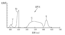
- the light source unit 20 includes a V-LED (VioletLightEmittingDiode) 20a, a B-LED (BlueLightEmittingDiode) 20b, a G-LED (GreenLightEmittingDiode) 20c, and an R-LED (Red). It has a 4-color LED of LightEmittingDiode) 20d and a wavelength cut filter 23. As shown in FIG. 3, the V-LED 20a emits purple light V having a wavelength band of 380 nm to 420 nm.
- the B-LED20b emits blue light B having a wavelength band of 420 nm to 500 nm.
- the blue light B emitted from the B-LED 23b at least the wavelength side longer than the peak wavelength of 450 nm is cut by the wavelength cut filter 23.
- the blue light Bx after passing through the wavelength cut filter 23 is in the wavelength range of 420 to 460 nm.
- the light in the wavelength region longer than 460 nm is cut because the light in the wavelength region longer than 460 nm reduces the vascular contrast of the blood vessel to be observed. Because there is.
- the wavelength cut filter 23 may dimming the light in the wavelength region longer than 460 nm instead of cutting the light in the wavelength region longer than 460 nm.
- the G-LED20c emits green light G having a wavelength band of 480 nm to 600 nm.
- the R-LED20d emits red light R having a wavelength band of 600 nm to 650 nm.
- the light emitted from each of the LEDs 20a to 20d may have the same center wavelength and the peak wavelength, or may be different from each other.
- the light source control unit 22 adjusts the emission timing, emission period, light amount, and spectral spectrum of the illumination light by independently controlling the lighting and extinguishing of the LEDs 20a to 20d and the amount of light emitted at the time of lighting.
- the control of turning on and off in the light source control unit 22 is different for each observation mode.
- the reference brightness can be set by the brightness setting unit of the light source device 14, the console 19, or the like.
- the light source control unit 22 lights all the V-LED20a, B-LED20b, G-LED20c, and R-LED20d.
- the peak of the light intensity of the blue light Bx is the purple light V, the green light G.
- red light R are set to be larger than the peak of any of the light intensities.
- the light source control unit 22 lights all the V-LED20a, B-LED20b, G-LED20c, and R-LED20d.
- the light intensity ratio Ls between the purple light V, the blue light B, the green light G, and the red light R has a peak of the light intensity of the purple light V, which is the blue light Bx and the green light G.
- red light R are set to be larger than the peak of any of the light intensities.
- the peaks of the light intensities of the green light G and the red light R are set to be smaller than the peaks of the light intensities of the purple light V and the blue light Bx.
- the light source device 14 emits multicolored light for the special mode including purple light V, blue light Bx, green light G, and red light R as special light.
- the special light is bluish because the proportion of purple light V is large.
- the special light does not have to include light of all four colors, and may include light from at least one of the four color LEDs 20a to 20d. Further, the special light preferably has a main wavelength range of 450 nm or less, for example, a peak wavelength or a center wavelength.
- the illumination light emitted by the light source unit 20 is incident on the light guide 24 inserted into the insertion unit 12a via an optical path coupling portion (not shown) formed by a mirror, a lens, or the like.
- the light guide 24 is built in the endoscope 12 and the universal cord, and propagates the illumination light to the tip portion 12d of the endoscope 12.
- the universal cord is a cord that connects the endoscope 12, the light source device 14, and the processor device 16.
- a multimode fiber can be used as the light guide 24.
- a fine fiber cable having a core diameter of 105 ⁇ m, a clad diameter of 125 ⁇ m, and a diameter of ⁇ 0.3 mm to ⁇ 0.5 mm including a protective layer serving as an outer skin can be used for the light guide 24.
- the tip portion 12d of the endoscope 12 is provided with an illumination optical system 30a and an imaging optical system 30b.
- the illumination optical system 30a has an illumination lens 32.
- the observation target is illuminated by the illumination light propagating through the illumination lens 32 and propagating through the light guide 24.
- the image pickup optical system 30b includes an objective lens 34, a magnifying optical system 36, and an image pickup sensor 38.
- Various types of light such as reflected light, scattered light, and fluorescence from the observation target are incident on the image pickup sensor 38 through the objective lens 34 and the magnifying optical system 36. As a result, an image to be observed is formed on the image sensor 38.
- the magnifying optical system 36 includes a zoom lens 36a that magnifies the observation target and a lens driving unit 36b that moves the zoom lens 36a in the optical axis direction CL.
- the zoom lens 36a is freely moved between the telephoto end and the wide-angle end according to the zoom control by the lens driving unit 36b, thereby enlarging or reducing the observation target imaged on the image sensor 38.
- the image sensor 38 is a color image sensor that captures an observation target irradiated with illumination light.
- Each pixel of the image sensor 38 is provided with any one of an R (red) color filter, a G (green) color filter, and a B (blue) color filter.
- the image pickup sensor 38 receives purple to blue light from the B pixel provided with the B color filter, receives green light from the G pixel provided with the G color filter, and is provided with the R color filter.
- the existing R pixel receives red light.
- the image signals of each RGB color are output from the pixels of each color.
- the image sensor 38 transmits the output image signal to the CDS circuit 40.
- the image sensor 38 In the normal mode or the region of interest mode, the image sensor 38 outputs a Bc image signal from the B pixel, outputs a Gc image signal from the G pixel, and outputs an R pixel by imaging an observation target illuminated with normal light. Outputs an Rc image signal from. Further, in the special mode, the image sensor 38 outputs a Bs image signal from the B pixel, outputs a Gs image signal from the G pixel, and Rs from the R pixel by imaging the observation target illuminated with the special light. Output the image signal.
- a CCD (Charge Coupled Device) image sensor, a CMOS (Complementary Metal-Oxide Semiconductor) image sensor, or the like can be used.
- a complementary color imaging sensor provided with complementary color filters of C (cyan), M (magenta), Y (yellow) and G (green) may be used. good.
- the image signals of four colors of CMYG are output. Therefore, by converting the image signals of the four colors of CMYG into the image signals of the three colors of RGB by the complementary color-primary color conversion, it is possible to obtain the image signals of each RGB color similar to the image sensor 38.
- a monochrome sensor without a color filter may be used.
- the CDS circuit 40 performs correlated double sampling (CDS: Correlated Double Sampling) on the analog image signal received from the image sensor 38.
- CDS Correlated Double Sampling
- the image signal that has passed through the CDS circuit 40 is input to the AGC circuit 42.
- the AGC circuit 40 performs automatic gain control (AGC: Automatic Gain Control) on the input image signal.
- a / D (Analog to Digital) conversion circuit 44 converts an analog image signal that has passed through the AGC circuit 42 into a digital image signal.
- the A / D conversion circuit 44 inputs the digital image signal after the A / D conversion to the processor device 16.
- the processor device 16 includes a control unit 46 that constitutes the processor of the present invention.
- the control unit 46 is a hardware resource for executing the program instructions stored in the memory 48, and drives and controls each unit of the endoscope system 10 to execute the program instructions.
- the processor device 16 includes the image signal acquisition unit 50, the DSP (Digital Signal Processor) 52, the noise reduction unit 54, the image processing unit 56, and the display control unit. Functions as 58.
- the image signal acquisition unit 50 drives and controls the endoscope 12 (imaging sensor 38, etc.) to perform imaging, and acquires an endoscope image (medical image).
- the image signal acquisition unit 50 sequentially acquires a plurality of endoscopic images by continuously imaging the observation target.
- the image signal acquisition unit 50 acquires an endoscopic image as a digital image signal corresponding to the observation mode. Specifically, in the case of the normal mode or the region of interest mode, the Bc image signal, the Gc image signal, and the Rc image signal are acquired. In the case of the special mode, the Bs image signal, the Gs image signal, and the Rs image signal are acquired.
- one frame of Bc image signal, Gc image signal, and Rc image signal is acquired when the normal light is illuminated
- one frame of Bs image signal, Gs image signal, and Rs is acquired when the special light is illuminated. Acquire an image signal.
- the DSP 52 performs various signal processing such as defect correction processing, offset processing, gain correction processing for DSP, linear matrix processing, gamma conversion processing, and demosaic processing on the image signal acquired by the image signal acquisition unit 50.
- the defect correction process corrects the signal of the defective pixel of the image sensor 38.
- the offset processing removes the dark current component from the defect-corrected image signal and sets an accurate zero level.
- the DSP gain correction process adjusts the signal level by multiplying the offset-processed image signal by a specific DSP gain.
- the linear matrix processing enhances the color reproducibility of the image signal that has been gain-corrected for DSP.
- the gamma conversion process adjusts the brightness and saturation of the image signal processed by the linear matrix.
- the gamma-converted image signal is subjected to demosaic processing (also referred to as isotropic processing or simultaneous processing) to generate a signal of a color lacking in each pixel by interpolation. By this demosaic processing, all the pixels have RGB signals of each color.
- the noise reduction unit 54 reduces noise by performing noise reduction processing by, for example, a moving average method, a median filter method, or the like on an image signal that has undergone demosaic processing or the like by DSP 52.
- the image signal after noise reduction is input to the image processing unit 56.
- the image processing unit 56 includes a normal mode image processing unit 60, a special mode image processing unit 62, and a region of interest mode image processing unit 64.
- the normal mode image processing unit 60 operates when the normal mode is set, and performs color conversion processing, color enhancement processing, and structure enhancement processing on the received Bc image signal, Gc image signal, and Rc image signal. conduct.
- the RGB image signal is subjected to color conversion processing by 3 ⁇ 3 matrix processing, gradation conversion processing, three-dimensional LUT (Look Up Table) processing, or the like.
- the color enhancement process is performed on the RGB image signal that has undergone the color conversion process.
- the structure enhancement process is a process for emphasizing the structure of the observation target, and is performed on the RGB image signal after the color enhancement process.
- a normal image can be obtained by performing various image processing and the like as described above. Since the normal image is an image obtained based on normal light in which purple light V, blue light Bx, green light G, and red light R are emitted in a well-balanced manner, it is an image having a natural hue.
- the special mode image processing unit 62 operates when the special mode is set.
- the special mode image processing unit 62 performs color conversion processing, color enhancement processing, and structure enhancement processing on the received Bs image signal, Gs image signal, and Rs image signal.
- the processing contents of the color conversion processing, the color enhancement processing, and the structure enhancement processing are the same as those of the normal mode image processing unit 60.
- a special image can be obtained by performing various image processing as described above.
- the special image is an image obtained based on special light in which purple light V, which has a high absorption coefficient of hemoglobin in blood vessels, emits more light than blue light Bx, green light G, and red light R of other colors. Therefore, the resolution of the vascular structure and the ductal structure is higher than that of other structures.
- the attention area mode image processing unit 64 operates when it is set in the attention area mode.
- the attention area mode image processing unit 64 performs the same image processing as the normal mode image processing unit 60 on the received Bc image signal, Gc image signal, and Rc image signal, such as color conversion processing.
- the attention area mode image processing unit 64 functions as the recognition processing unit 72 and the recognition result correction unit 73 by the drive control of the control unit 46 (see FIG. 2) accompanying the execution of the program instruction described above. do.
- the recognition processing unit 72 sequentially acquires endoscopic images by the same image processing as the normal mode image processing unit 60, analyzes the acquired endoscopic images, and performs recognition processing.
- the recognition process performed by the recognition processing unit 72 includes a detection process for detecting a region of interest from a recognition image (endoscopic image in the present embodiment) and a discrimination process for distinguishing the type of lesion included in the recognition image. And are included. Further, the discrimination process includes a process performed on the region of interest and a process performed on the entire recognition image.
- the recognition processing unit 72 performs detection processing for detecting a rectangular region including a lesion portion as a region of interest from an endoscopic image.
- the recognition processing unit 72 first divides the endoscopic image into a plurality of small areas, for example, a square area for several pixels. Next, the image feature amount is calculated from the divided endoscopic images. Subsequently, based on the calculated feature amount, it is determined whether or not each small region is a lesion. Finally, a group of small regions identified as the same type is extracted as one lesion, and a rectangular region including the extracted lesion is detected as a region of interest.
- a machine learning algorithm such as a convolutional neural network or deep learning is preferable.
- the feature amount calculated from the endoscopic image by the recognition processing unit 72 is preferably an index value obtained from the shape and color of a predetermined portion in the observation target or those shapes and colors.
- an index value obtained from the shape and color of a predetermined portion in the observation target or those shapes and colors.
- the value is at least one of the length, the degree of tortuosity of the blood vessel, and the color information, or a combination of two or more of them.
- the recognition result correction unit 73 performs the recognition result correction process for correcting the recognition process result performed by the recognition processing unit 72.
- the recognition result correction process will be described.
- the endoscopic image obtained from which the recognition process result to be the target of the recognition result correction process is obtained is referred to as a specific image 80 (specific medical image) (FIG. 8).
- the position information of the attention region 82ROI of the pre-image 82 (medical image for comparison) acquired (imaged) before the specific image 80 and the specific image 80 are used.
- the position information of the attention region 80ROI of the specific image 80 is corrected by using the position information of the attention region 84ROI of the image 84 (medical image for comparison) after being acquired (imaged) later.
- the front image 82 is an endoscopic image acquired (captured) at the time “t ⁇ ” when the time when the specific image 80 was acquired (captured) is “t”.
- the value of " ⁇ ” can be set as appropriate, in the present embodiment, the value of " ⁇ ” is set so that the image acquired (captured) immediately before the specific image 80 becomes the front image 82. That is, for example, when an image is taken at a cycle of 60 times per second (frame) to acquire an endoscopic image, " ⁇ " is set to "1/60 (second)".
- the rear image 84 is an endoscopic image acquired (captured) at the time "t + ⁇ " when the time when the specific image 80 was acquired (captured) is "t".
- the value of " ⁇ ” can be set as appropriate, in the present embodiment, the value of " ⁇ ” is set so that the image acquired (captured) immediately after the specific image 80 becomes the front image 82. That is, for example, when an image is taken at a cycle of 60 times per second (frame) to acquire an endoscopic image, " ⁇ " is set to "1/60 (second)".
- the specific image so that the intermediate position between the center of the attention region 82ROI of the front image 82 and the center of the attention region 84ROI of the rear image 84 coincides with the center of the attention region 80ROI of the specific image 80.
- the position (position information) of the area of interest 80ROI of 80 is changed (corrected). That is, the position information of the attention region 80ROI of the specific image 80 is corrected by using the linear sum of the position information of the attention regions 82ROI and 84ROI of the front image 82 and the rear image 84.
- the normal image generated by the normal mode image processing unit 60, the special image generated by the special mode image processing unit 62, and the processing result performed by the attention area mode image processing unit 64 (recognition processing).
- the result and the result of the recognition result correction process) are input to the display control unit 58.
- the display control unit 58 generates a display screen using the input information and outputs and displays it on the monitor 18.
- the normal image, the special image, and the processing result may be stored in the memory 48 or the like instead of or in addition to being output and displayed on the monitor 18.
- the feature amount used for the recognition process and / or the processing algorithm of the recognition process is not changed, and the recognition process is not performed again after such a change.
- the recognition processing result of the specific image 80 is corrected by using the recognition processing result of the above and the recognition processing result of the rear image 84.
- a more accurate recognition processing result can be obtained while reducing the processing load as compared with the case where the feature amount used for the recognition processing and / or the algorithm of the recognition processing is changed or the re-recognition processing is performed. be able to.
- the position (center position) of the attention region 80ROI of the specific image 80 is changed (see FIG. 8), but the size of the attention region 80ROI of the specific image 80 is changed. You may change it.
- the size of the attention area 80ROI of the specific image 80 is the average size (area) of the size (area) of the attention area 82ROI of the front image 82 and the size (area) of the attention area 84ROI of the rear image 84. Can be changed (enlarged or reduced).
- the intermediate position between the upper right corner of the attention area 82ROI of the front image 82 and the upper right corner of the attention area 84ROI of the rear image 84 becomes the upper right corner of the attention area 80ROI of the specific image 80, and the lower right corner of the attention area 80ROI.
- the intermediate position between the corner and the lower right corner of the attention area 84ROI is the lower right corner of the attention area 80ROI, and the intermediate position between the upper left corner of the attention area 82ROI and the upper left corner of the attention area 84ROI is the upper left corner of the attention area 80ROI.
- the size and center position of the region of interest 80ROI may be changed so that the intermediate position between the lower left corner of the region of interest 82ROI and the lower left corner of the region of interest 84ROI is the lower left corner of the region of interest 80ROI. ..
- the medical image for comparison pre-image 82 and rear image 84 in the first embodiment
- there may be a lesion portion that does not exist in the specific image 80 and such a comparative image is used.
- an appropriate correction cannot be performed. Therefore, it is preferable to correct the recognition result of the specific image 80 by using only the medical image for comparison in which the position of the region of interest is within a predetermined range from the position of the region of interest 80ROI of the specific image 80. By doing so, appropriate correction is performed, and a more accurate recognition processing result can be obtained.
- the recognition processing unit 72 detects the lesion portion from the specific image 80 as in the first embodiment, and further performs a discrimination process for discriminating the type of lesion or the like from the detected lesion portion, or the specific image. Discrimination processing is performed on the entire 80. Then, the recognition result correction unit 73 corrects the discrimination result of the specific image 80 by using the discrimination result of the front image 82 and the discrimination result of the rear image 84.
- the differentiation result of the attention region 82ROI of the front image 82 is “tumor”
- the differentiation result of the attention region 80ROI of the specific image 80 is “non-tumor”
- the differentiation result of the attention region 84ROI of the rear image 84 is “tumor”.
- the discrimination result of is "tumor”
- the discrimination result of the region of interest 80ROI of the specific image 80 is changed (corrected) to "tumor”. That is, among the numbers of the discrimination results of the front image 82 and the rear image 84 for each type, the discrimination result of the specific image 80 is corrected to the largest number of discrimination results (for each type of the discrimination result of the medical image for comparison). The number is used to correct the discrimination result of the specific image 80).
- AI Artificial Intelligence
- Convolutional neural network Convolutional Neural Network
- template matching texture analysis, frequency analysis, or the like. ..
- the recognition processing result of the specific image 80 is corrected by using the recognition processing result of one front image 82 and the recognition processing result of one rear image 84. Not limited. For example, as shown in FIGS. 10 and 11, even if the recognition processing result of the specific image 80 is corrected by using the recognition processing result of the plurality of front images 82 and the recognition processing result of the plurality of rear images 84. good.
- the recognition processing result of the specific image 80 is corrected by using the recognition processing result of the two front images 82 and the recognition processing result of the two rear images 84.
- the average position of the center position of the attention region 82ROI of the two front images 82 and the center position of the attention region 84ROI of the two rear images 84 is calculated, and the calculated position is The center position of the attention region 80ROI is corrected so as to be the center position of the attention region 80ROI of the specific image 80.
- the discrimination result of the specific image 80 is corrected to “tumor”, which is the most common discrimination result among the discrimination result of the two front images 82 and the discrimination result of the two rear images 84. ing.
- the recognition processing result of the specific image 80 may be corrected by using three or more front images 82 and rear images 84.
- the recognition processing result of the specific image 80 is corrected by using both the front image 82 and the rear image 84
- the recognition of the specific image 80 is performed by using only one of the front image 82 and the rear image 84.
- the processing result may be corrected.
- FIG. 10 when the recognition result of the specific image 80 is corrected using only the front image 82, the movement amount and the movement direction of the center of the attention region 82 ROI per unit time are compared by comparing the two front images 82.
- the position of the center of the region of interest 80ROI of the specific image 80 may be corrected by using the calculated movement amount and movement direction.
- FIG. 11 when the recognition result of the specific image 80 is corrected using only the front image 82, the specific image 80 is divided into the most types of the discrimination results of the two front images 82.
- the discrimination result may be corrected.
- the recognition result correction process may be performed.
- the recognition processing unit 72 executes the recognition process, calculates the certainty of the executed recognition process, and notifies the recognition result correction unit 73. Then, the recognition result correction unit 73 performs the recognition result correction process when the certainty of the result of the recognition process is less than a predetermined threshold value.
- the recognition processing result may be corrected when the user specifies it.
- the endoscope image acquired by the attention area mode image processing unit 64 or the recognition processing result performed by the recognition processing unit 72 is displayed on the monitor 18, and the user operates the console 19 while observing the monitor 18. Therefore, the target (endoscopic image or recognition processing result) to be subjected to the recognition result correction processing may be specified.
- the still image acquisition unit 13b is operated, it is considered that the user has specified the endoscopic image acquired by the operation of the still image acquisition unit 13b, and the recognition result correction processing may be performed.
- the recognition processing result correction processing is performed according to the user's designation
- what is required for the recognition processing result correction processing is the result of the recognition processing of the front image 82 and / or the rear image 84. Therefore, the recognition process for the endoscopic image other than this may be omitted.
- the processor device 16 which is a part of the endoscope system 10 functions as the processor of the present invention, that is, the control unit 46 which is the processor of the present invention is the endoscope system 10 (processor device 16).
- the endoscopic system 10 has been described as an example of functioning as the region of interest mode image processing unit 64, but the present invention is not limited thereto.
- an image processing device 110 is provided separately from the endoscope system 100, and the image processing device 110 is provided with a control unit 46 and a memory 48, and the image processing device 110 is provided.
- the configuration may be configured to function as the attention area mode image processing unit 64.
- the image processing device 110 is connected to the endoscope system 100, and an endoscope image is transmitted from the endoscope system 100 to the image processing device 110.
- the attention area mode image processing unit 64 performs the above-mentioned recognition processing and recognition result correction processing, and notifies the result of the recognition processing and recognition result correction processing to a predetermined notification destination (endoscope in the example of FIG. 14). Send to system 100).
- the above-mentioned image processing device 110 is connected to a device or system for acquiring a medical image other than the endoscopic image, and the medical image other than the endoscopic image is recognized and the recognition result is corrected. It may be configured as a processing system. Medical images other than endoscopy include ultrasonic images obtained by an ultrasonic diagnostic apparatus, X-ray images obtained by an X-ray inspection apparatus, CT images obtained by a CT (Computed Tomography) inspection apparatus, and MRI (Magnetic Resonance Imaging). ) MRI inspection image obtained by the inspection device and the like can be mentioned.
- the control unit 46 (processor) of the present invention includes a CPU (Central Processing Unit), a GPU (Graphical Processing Unit), which are general-purpose processors that function as various processing units such as the attention area mode image processing unit 64. FPGA (Field Programmable Gate Array) etc. are included. Further, the control unit 46 (processor) of the present invention includes not only a programmable logic device (Programmable Logic Device: PLD), which is a processor whose circuit configuration can be changed after manufacturing, such as a CPU, GPU, and FPGA, but also various types. It also includes a dedicated electric circuit, which is a processor having a circuit configuration designed exclusively for executing processing.
- PLD programmable logic device
- One processing unit may be composed of one of these various processors, or a combination of two or more processors of the same type or different types (for example, a plurality of FPGAs, a combination of a CPU and an FPGA, or a CPU. And GPU, etc.). Further, a plurality of processing units may be configured by one processor. As an example of configuring a plurality of processing units with one processor, first, as represented by a computer such as a client or a server, one processor is configured by a combination of one or more CPUs and software. There is a form in which this processor functions as a plurality of processing units.
- SoC System On Chip
- a processor that realizes the functions of the entire system including a plurality of processing units with one IC (Integrated Circuit) chip is used.
- the various processing units are configured by using one or more of the above-mentioned various processors as a hardware-like structure.
Landscapes
- Health & Medical Sciences (AREA)
- Life Sciences & Earth Sciences (AREA)
- Engineering & Computer Science (AREA)
- Surgery (AREA)
- Physics & Mathematics (AREA)
- Medical Informatics (AREA)
- General Health & Medical Sciences (AREA)
- Radiology & Medical Imaging (AREA)
- Nuclear Medicine, Radiotherapy & Molecular Imaging (AREA)
- Molecular Biology (AREA)
- Veterinary Medicine (AREA)
- Biomedical Technology (AREA)
- Heart & Thoracic Surgery (AREA)
- Optics & Photonics (AREA)
- Biophysics (AREA)
- Animal Behavior & Ethology (AREA)
- Pathology (AREA)
- Public Health (AREA)
- Signal Processing (AREA)
- Quality & Reliability (AREA)
- Computer Vision & Pattern Recognition (AREA)
- General Physics & Mathematics (AREA)
- Theoretical Computer Science (AREA)
- Artificial Intelligence (AREA)
- Evolutionary Computation (AREA)
- Microelectronics & Electronic Packaging (AREA)
- Endoscopes (AREA)
- Measuring And Recording Apparatus For Diagnosis (AREA)
Priority Applications (2)
| Application Number | Priority Date | Filing Date | Title |
|---|---|---|---|
| JP2022511709A JP7402314B2 (ja) | 2020-04-02 | 2021-03-05 | 医用画像処理システム、医用画像処理システムの作動方法 |
| US17/937,266 US20230029239A1 (en) | 2020-04-02 | 2022-09-30 | Medical image processing system and method for operating medical image processing system |
Applications Claiming Priority (2)
| Application Number | Priority Date | Filing Date | Title |
|---|---|---|---|
| JP2020066912 | 2020-04-02 | ||
| JP2020-066912 | 2020-04-02 |
Related Child Applications (1)
| Application Number | Title | Priority Date | Filing Date |
|---|---|---|---|
| US17/937,266 Continuation US20230029239A1 (en) | 2020-04-02 | 2022-09-30 | Medical image processing system and method for operating medical image processing system |
Publications (1)
| Publication Number | Publication Date |
|---|---|
| WO2021199910A1 true WO2021199910A1 (ja) | 2021-10-07 |
Family
ID=77930201
Family Applications (1)
| Application Number | Title | Priority Date | Filing Date |
|---|---|---|---|
| PCT/JP2021/008739 Ceased WO2021199910A1 (ja) | 2020-04-02 | 2021-03-05 | 医用画像処理システム、医用画像処理システムの作動方法 |
Country Status (3)
| Country | Link |
|---|---|
| US (1) | US20230029239A1 (https=) |
| JP (1) | JP7402314B2 (https=) |
| WO (1) | WO2021199910A1 (https=) |
Cited By (1)
| Publication number | Priority date | Publication date | Assignee | Title |
|---|---|---|---|---|
| EP4327718A1 (en) * | 2022-08-26 | 2024-02-28 | FUJIFILM Corporation | Image processing device, method for operating the same, and endoscope system |
Families Citing this family (3)
| Publication number | Priority date | Publication date | Assignee | Title |
|---|---|---|---|---|
| EP3337419B1 (en) * | 2015-08-19 | 2020-08-12 | Brainlab AG | Reference array holder |
| WO2021172131A1 (ja) * | 2020-02-28 | 2021-09-02 | 富士フイルム株式会社 | 内視鏡システム、及び内視鏡システムの作動方法 |
| JP7603560B2 (ja) * | 2021-09-17 | 2024-12-20 | Hoya株式会社 | コンピュータプログラム、情報処理方法及び内視鏡 |
Citations (7)
| Publication number | Priority date | Publication date | Assignee | Title |
|---|---|---|---|---|
| JP2007330764A (ja) * | 2006-01-10 | 2007-12-27 | Toshiba Corp | 超音波診断装置及び超音波画像生成方法 |
| JP2008006188A (ja) * | 2006-06-30 | 2008-01-17 | Fujifilm Corp | 医用画像表示処理装置、及び、医用画像表示処理プログラム |
| JP2010131371A (ja) * | 2008-10-27 | 2010-06-17 | Toshiba Corp | X線診断装置および画像処理装置 |
| JP2013013569A (ja) * | 2011-07-04 | 2013-01-24 | Hoya Corp | 画像処理装置、画像処理方法、及び画像処理ソフトウェア |
| WO2018216617A1 (ja) * | 2017-05-25 | 2018-11-29 | 日本電気株式会社 | 情報処理装置、制御方法、及びプログラム |
| WO2019123986A1 (ja) * | 2017-12-22 | 2019-06-27 | 富士フイルム株式会社 | 医療画像処理装置及び方法、内視鏡システム、プロセッサ装置、診断支援装置並びにプログラム |
| WO2019235195A1 (ja) * | 2018-06-04 | 2019-12-12 | 富士フイルム株式会社 | 画像処理装置、内視鏡システム、及び画像処理方法 |
-
2021
- 2021-03-05 JP JP2022511709A patent/JP7402314B2/ja active Active
- 2021-03-05 WO PCT/JP2021/008739 patent/WO2021199910A1/ja not_active Ceased
-
2022
- 2022-09-30 US US17/937,266 patent/US20230029239A1/en active Pending
Patent Citations (7)
| Publication number | Priority date | Publication date | Assignee | Title |
|---|---|---|---|---|
| JP2007330764A (ja) * | 2006-01-10 | 2007-12-27 | Toshiba Corp | 超音波診断装置及び超音波画像生成方法 |
| JP2008006188A (ja) * | 2006-06-30 | 2008-01-17 | Fujifilm Corp | 医用画像表示処理装置、及び、医用画像表示処理プログラム |
| JP2010131371A (ja) * | 2008-10-27 | 2010-06-17 | Toshiba Corp | X線診断装置および画像処理装置 |
| JP2013013569A (ja) * | 2011-07-04 | 2013-01-24 | Hoya Corp | 画像処理装置、画像処理方法、及び画像処理ソフトウェア |
| WO2018216617A1 (ja) * | 2017-05-25 | 2018-11-29 | 日本電気株式会社 | 情報処理装置、制御方法、及びプログラム |
| WO2019123986A1 (ja) * | 2017-12-22 | 2019-06-27 | 富士フイルム株式会社 | 医療画像処理装置及び方法、内視鏡システム、プロセッサ装置、診断支援装置並びにプログラム |
| WO2019235195A1 (ja) * | 2018-06-04 | 2019-12-12 | 富士フイルム株式会社 | 画像処理装置、内視鏡システム、及び画像処理方法 |
Cited By (1)
| Publication number | Priority date | Publication date | Assignee | Title |
|---|---|---|---|---|
| EP4327718A1 (en) * | 2022-08-26 | 2024-02-28 | FUJIFILM Corporation | Image processing device, method for operating the same, and endoscope system |
Also Published As
| Publication number | Publication date |
|---|---|
| JPWO2021199910A1 (https=) | 2021-10-07 |
| JP7402314B2 (ja) | 2023-12-20 |
| US20230029239A1 (en) | 2023-01-26 |
Similar Documents
| Publication | Publication Date | Title |
|---|---|---|
| JP6785948B2 (ja) | 医療用画像処理装置及び内視鏡システム並びに医療用画像処理装置の作動方法 | |
| JP7542585B2 (ja) | 画像処理装置、内視鏡システム及び画像処理装置の作動方法 | |
| US11627864B2 (en) | Medical image processing apparatus, endoscope system, and method for emphasizing region of interest | |
| JP7402314B2 (ja) | 医用画像処理システム、医用画像処理システムの作動方法 | |
| JP7335399B2 (ja) | 医用画像処理装置及び内視鏡システム並びに医用画像処理装置の作動方法 | |
| US20230027950A1 (en) | Medical image processing apparatus, endoscope system, method of operating medical image processing apparatus, and non-transitory computer readable medium | |
| JP6917518B2 (ja) | 内視鏡システム | |
| US20190246874A1 (en) | Processor device, endoscope system, and method of operating processor device | |
| EP4183311A1 (en) | Image analysis processing device, endoscopy system, operation method for image analysis processing device, and program for image analysis processing device | |
| JP7610342B2 (ja) | 内視鏡システム | |
| US11969152B2 (en) | Medical image processing system | |
| JP7130043B2 (ja) | 医用画像処理装置及び内視鏡システム並びに医用画像処理装置の作動方法 | |
| US11744437B2 (en) | Medical image processing system | |
| JP7447243B2 (ja) | プロセッサ装置及びその作動方法 | |
| US12620474B2 (en) | Medical image processing apparatus, endoscope system, method of operating medical image processing apparatus, and non-transitory computer readable medium | |
| WO2021210676A1 (ja) | 医療画像処理装置、内視鏡システム及び医療画像処理装置の作動方法並びに医療画像処理装置用プログラム | |
| JP2022090759A (ja) | 医用画像処理システム、医用画像処理システムの作動方法 |
Legal Events
| Date | Code | Title | Description |
|---|---|---|---|
| 121 | Ep: the epo has been informed by wipo that ep was designated in this application |
Ref document number: 21782080 Country of ref document: EP Kind code of ref document: A1 |
|
| ENP | Entry into the national phase |
Ref document number: 2022511709 Country of ref document: JP Kind code of ref document: A |
|
| NENP | Non-entry into the national phase |
Ref country code: DE |
|
| 122 | Ep: pct application non-entry in european phase |
Ref document number: 21782080 Country of ref document: EP Kind code of ref document: A1 |