WO2021199910A1 - Medical image processing system and method for operating medical image processing system - Google Patents
Medical image processing system and method for operating medical image processing system Download PDFInfo
- Publication number
- WO2021199910A1 WO2021199910A1 PCT/JP2021/008739 JP2021008739W WO2021199910A1 WO 2021199910 A1 WO2021199910 A1 WO 2021199910A1 JP 2021008739 W JP2021008739 W JP 2021008739W WO 2021199910 A1 WO2021199910 A1 WO 2021199910A1
- Authority
- WO
- WIPO (PCT)
- Prior art keywords
- image
- medical image
- region
- processing system
- image processing
- Prior art date
Links
Images


Classifications
-
- A—HUMAN NECESSITIES
- A61—MEDICAL OR VETERINARY SCIENCE; HYGIENE
- A61B—DIAGNOSIS; SURGERY; IDENTIFICATION
- A61B1/00—Instruments for performing medical examinations of the interior of cavities or tubes of the body by visual or photographical inspection, e.g. endoscopes; Illuminating arrangements therefor
- A61B1/00002—Operational features of endoscopes
- A61B1/00004—Operational features of endoscopes characterised by electronic signal processing
- A61B1/00009—Operational features of endoscopes characterised by electronic signal processing of image signals during a use of endoscope
- A61B1/000094—Operational features of endoscopes characterised by electronic signal processing of image signals during a use of endoscope extracting biological structures
-
- A—HUMAN NECESSITIES
- A61—MEDICAL OR VETERINARY SCIENCE; HYGIENE
- A61B—DIAGNOSIS; SURGERY; IDENTIFICATION
- A61B1/00—Instruments for performing medical examinations of the interior of cavities or tubes of the body by visual or photographical inspection, e.g. endoscopes; Illuminating arrangements therefor
- A61B1/00002—Operational features of endoscopes
- A61B1/00004—Operational features of endoscopes characterised by electronic signal processing
- A61B1/00009—Operational features of endoscopes characterised by electronic signal processing of image signals during a use of endoscope
- A61B1/000095—Operational features of endoscopes characterised by electronic signal processing of image signals during a use of endoscope for image enhancement
-
- A—HUMAN NECESSITIES
- A61—MEDICAL OR VETERINARY SCIENCE; HYGIENE
- A61B—DIAGNOSIS; SURGERY; IDENTIFICATION
- A61B1/00—Instruments for performing medical examinations of the interior of cavities or tubes of the body by visual or photographical inspection, e.g. endoscopes; Illuminating arrangements therefor
- A61B1/00002—Operational features of endoscopes
- A61B1/00004—Operational features of endoscopes characterised by electronic signal processing
- A61B1/00009—Operational features of endoscopes characterised by electronic signal processing of image signals during a use of endoscope
- A61B1/000096—Operational features of endoscopes characterised by electronic signal processing of image signals during a use of endoscope using artificial intelligence
-
- A—HUMAN NECESSITIES
- A61—MEDICAL OR VETERINARY SCIENCE; HYGIENE
- A61B—DIAGNOSIS; SURGERY; IDENTIFICATION
- A61B1/00—Instruments for performing medical examinations of the interior of cavities or tubes of the body by visual or photographical inspection, e.g. endoscopes; Illuminating arrangements therefor
- A61B1/00002—Operational features of endoscopes
- A61B1/00043—Operational features of endoscopes provided with output arrangements
- A61B1/00045—Display arrangement
-
- A—HUMAN NECESSITIES
- A61—MEDICAL OR VETERINARY SCIENCE; HYGIENE
- A61B—DIAGNOSIS; SURGERY; IDENTIFICATION
- A61B1/00—Instruments for performing medical examinations of the interior of cavities or tubes of the body by visual or photographical inspection, e.g. endoscopes; Illuminating arrangements therefor
- A61B1/00163—Optical arrangements
- A61B1/00188—Optical arrangements with focusing or zooming features
-
- A—HUMAN NECESSITIES
- A61—MEDICAL OR VETERINARY SCIENCE; HYGIENE
- A61B—DIAGNOSIS; SURGERY; IDENTIFICATION
- A61B1/00—Instruments for performing medical examinations of the interior of cavities or tubes of the body by visual or photographical inspection, e.g. endoscopes; Illuminating arrangements therefor
- A61B1/04—Instruments for performing medical examinations of the interior of cavities or tubes of the body by visual or photographical inspection, e.g. endoscopes; Illuminating arrangements therefor combined with photographic or television appliances
- A61B1/045—Control thereof
-
- A—HUMAN NECESSITIES
- A61—MEDICAL OR VETERINARY SCIENCE; HYGIENE
- A61B—DIAGNOSIS; SURGERY; IDENTIFICATION
- A61B1/00—Instruments for performing medical examinations of the interior of cavities or tubes of the body by visual or photographical inspection, e.g. endoscopes; Illuminating arrangements therefor
- A61B1/04—Instruments for performing medical examinations of the interior of cavities or tubes of the body by visual or photographical inspection, e.g. endoscopes; Illuminating arrangements therefor combined with photographic or television appliances
- A61B1/05—Instruments for performing medical examinations of the interior of cavities or tubes of the body by visual or photographical inspection, e.g. endoscopes; Illuminating arrangements therefor combined with photographic or television appliances characterised by the image sensor, e.g. camera, being in the distal end portion
-
- A—HUMAN NECESSITIES
- A61—MEDICAL OR VETERINARY SCIENCE; HYGIENE
- A61B—DIAGNOSIS; SURGERY; IDENTIFICATION
- A61B1/00—Instruments for performing medical examinations of the interior of cavities or tubes of the body by visual or photographical inspection, e.g. endoscopes; Illuminating arrangements therefor
- A61B1/06—Instruments for performing medical examinations of the interior of cavities or tubes of the body by visual or photographical inspection, e.g. endoscopes; Illuminating arrangements therefor with illuminating arrangements
- A61B1/0638—Instruments for performing medical examinations of the interior of cavities or tubes of the body by visual or photographical inspection, e.g. endoscopes; Illuminating arrangements therefor with illuminating arrangements providing two or more wavelengths
-
- A—HUMAN NECESSITIES
- A61—MEDICAL OR VETERINARY SCIENCE; HYGIENE
- A61B—DIAGNOSIS; SURGERY; IDENTIFICATION
- A61B1/00—Instruments for performing medical examinations of the interior of cavities or tubes of the body by visual or photographical inspection, e.g. endoscopes; Illuminating arrangements therefor
- A61B1/06—Instruments for performing medical examinations of the interior of cavities or tubes of the body by visual or photographical inspection, e.g. endoscopes; Illuminating arrangements therefor with illuminating arrangements
- A61B1/0646—Instruments for performing medical examinations of the interior of cavities or tubes of the body by visual or photographical inspection, e.g. endoscopes; Illuminating arrangements therefor with illuminating arrangements with illumination filters
-
- A—HUMAN NECESSITIES
- A61—MEDICAL OR VETERINARY SCIENCE; HYGIENE
- A61B—DIAGNOSIS; SURGERY; IDENTIFICATION
- A61B1/00—Instruments for performing medical examinations of the interior of cavities or tubes of the body by visual or photographical inspection, e.g. endoscopes; Illuminating arrangements therefor
- A61B1/06—Instruments for performing medical examinations of the interior of cavities or tubes of the body by visual or photographical inspection, e.g. endoscopes; Illuminating arrangements therefor with illuminating arrangements
- A61B1/0655—Control therefor
-
- A—HUMAN NECESSITIES
- A61—MEDICAL OR VETERINARY SCIENCE; HYGIENE
- A61B—DIAGNOSIS; SURGERY; IDENTIFICATION
- A61B1/00—Instruments for performing medical examinations of the interior of cavities or tubes of the body by visual or photographical inspection, e.g. endoscopes; Illuminating arrangements therefor
- A61B1/06—Instruments for performing medical examinations of the interior of cavities or tubes of the body by visual or photographical inspection, e.g. endoscopes; Illuminating arrangements therefor with illuminating arrangements
- A61B1/0661—Endoscope light sources
- A61B1/0684—Endoscope light sources using light emitting diodes [LED]
-
- A—HUMAN NECESSITIES
- A61—MEDICAL OR VETERINARY SCIENCE; HYGIENE
- A61B—DIAGNOSIS; SURGERY; IDENTIFICATION
- A61B1/00—Instruments for performing medical examinations of the interior of cavities or tubes of the body by visual or photographical inspection, e.g. endoscopes; Illuminating arrangements therefor
- A61B1/06—Instruments for performing medical examinations of the interior of cavities or tubes of the body by visual or photographical inspection, e.g. endoscopes; Illuminating arrangements therefor with illuminating arrangements
- A61B1/07—Instruments for performing medical examinations of the interior of cavities or tubes of the body by visual or photographical inspection, e.g. endoscopes; Illuminating arrangements therefor with illuminating arrangements using light-conductive means, e.g. optical fibres
-
- A—HUMAN NECESSITIES
- A61—MEDICAL OR VETERINARY SCIENCE; HYGIENE
- A61B—DIAGNOSIS; SURGERY; IDENTIFICATION
- A61B5/00—Measuring for diagnostic purposes; Identification of persons
-
- G—PHYSICS
- G06—COMPUTING; CALCULATING OR COUNTING
- G06T—IMAGE DATA PROCESSING OR GENERATION, IN GENERAL
- G06T7/00—Image analysis
- G06T7/0002—Inspection of images, e.g. flaw detection
- G06T7/0012—Biomedical image inspection
-
- G—PHYSICS
- G06—COMPUTING; CALCULATING OR COUNTING
- G06T—IMAGE DATA PROCESSING OR GENERATION, IN GENERAL
- G06T2207/00—Indexing scheme for image analysis or image enhancement
- G06T2207/10—Image acquisition modality
- G06T2207/10068—Endoscopic image
-
- G—PHYSICS
- G06—COMPUTING; CALCULATING OR COUNTING
- G06T—IMAGE DATA PROCESSING OR GENERATION, IN GENERAL
- G06T2207/00—Indexing scheme for image analysis or image enhancement
- G06T2207/20—Special algorithmic details
- G06T2207/20084—Artificial neural networks [ANN]
-
- G—PHYSICS
- G06—COMPUTING; CALCULATING OR COUNTING
- G06T—IMAGE DATA PROCESSING OR GENERATION, IN GENERAL
- G06T2207/00—Indexing scheme for image analysis or image enhancement
- G06T2207/30—Subject of image; Context of image processing
- G06T2207/30004—Biomedical image processing
- G06T2207/30096—Tumor; Lesion
Definitions
- the present invention relates to a medical image processing system and a method of operating a medical image processing system.
- medical images such as endoscopic images, X-ray images, CT (Computed Tomography) images, and MR (Magnetic Resonanse) images are used to diagnose the patient's medical condition and perform diagnostic imaging such as follow-up. ing. Based on such diagnostic imaging, doctors and the like make decisions on treatment policies.
- Patent Document 1 recognition processing is performed on each of a plurality of medical images sequentially acquired by continuous imaging to calculate the feature amount of the image, and images are taken before and after the image on which the recognition processing is performed. A configuration is described in which the feature amount calculated in the recognition process is corrected using a medical image, and the recognition process is performed again using the corrected feature amount.
- Patent Document 1 the feature amount is corrected and the re-recognition process is performed to obtain a more accurate recognition result, but there is a problem that the processing load for obtaining the recognition result is large.
- the present invention has been made in view of the above background, and provides an operation method of a medical image processing system and a medical image processing system capable of obtaining more accurate recognition results while reducing the processing load. I am aiming.
- the medical image processing system of the present invention is a medical image processing system including a memory for storing a program instruction and a processor for executing the program instruction, in which the processor continuously observes an observation target.
- a region of interest is detected from the medical images and the identification of the plurality of medical images is performed.
- the position information of the region of interest detected by the recognition process performed on the medical image of the above was detected by the recognition process performed on the comparison medical image captured at least one before and after the specific medical image. Correct using the position information of the area of interest.
- the correction may be performed when the certainty of the result of the recognition process falls below a predetermined threshold value.
- the correction may be performed when the user instructs it.
- the linear sum of the position information of the region of interest of the medical image for comparison may be used.
- the position information of the attention area located within a predetermined range from the attention area of the specific medical image among the attention areas of the medical image for comparison may be used.
- the recognition process may include a discrimination process for discriminating the region of interest.
- the result of discrimination may be corrected.
- the number for each type of the discrimination result of the medical image for comparison may be used.
- Convolutional Neural Network may be used.
- the medical image may be an image obtained from an endoscope.
- the method of operating the medical image processing system of the present invention is the method of operating the medical image processing system including a memory for storing program instructions and a processor for executing the program instructions.
- the processor sequentially acquires a plurality of medical images generated by continuously capturing an observation target, and performs recognition processing on each of the plurality of medical images to detect a region of interest from the medical images.
- the position information of the region of interest detected by the recognition process performed on a specific medical image among a plurality of medical images is applied to a comparative medical image captured at least one before and after the specific medical image. Correction is performed using the position information of the region of interest detected by the recognized recognition process.
- the endoscope system 10 (medical image processing system) includes an endoscope 12, a light source device 14, a processor device 16, a monitor 18, and a console 19.
- the endoscope 12 is optically connected to the light source device 14 and electrically connected to the processor device 16.
- the endoscope 12 has an insertion portion 12a to be inserted into the subject, an operation portion 12b provided at the base end portion of the insertion portion 12a, and a curved portion 12c and a tip portion 12d provided on the tip end side of the insertion portion 12a. doing.
- the angle knob 13a of the operation unit 12b By operating the angle knob 13a of the operation unit 12b, the bending unit 12c bends. This bending motion directs the tip 12d in a desired direction.
- the operation unit 12b includes a still image acquisition unit 13b used for still image acquisition operation, a mode switching unit 13c used for observation mode switching operation, and a zoom operation unit 13d used for zoom magnification changing operation. Is provided.
- the still image acquisition unit 13b can perform a freeze operation for displaying the still image to be observed on the monitor 18 and a release operation for saving the still image in the storage.
- the endoscope system 10 has a normal mode, a special mode, and a region of interest mode as observation modes.
- the observation mode is the normal mode
- the normal light obtained by combining the light of a plurality of colors with the light amount ratio Lc for the normal mode is emitted.
- the observation mode is the special mode
- the special light obtained by combining the light of a plurality of colors with the light amount ratio Ls for the special mode is emitted.
- the illumination light for the attention area mode is emitted.
- normal light is emitted as the illumination light for the region of interest mode, but special light may be emitted.
- the processor device 16 is electrically connected to the monitor 18 and the console 19.
- the monitor 18 outputs and displays an image to be observed, information incidental to the image, and the like.
- the console 19 functions as a user interface that accepts input operations such as specifying a region of interest (ROI: RegionOfInterest), specifying an image to perform recognition processing, specifying an image to perform recognition result correction processing or a recognition processing result, and setting functions. do.
- ROI region of interest
- the light source device 14 includes a light source unit 20 that emits illumination light used for illuminating an observation target, and a light source control unit 22 that controls the light source unit 20.
- the light source unit 20 is a semiconductor light source such as a multi-color LED (Light Emitting Diode).
- the light source control unit 22 controls the amount of light emitted from the illumination light by turning on / off the LED and the like, and adjusting the drive current and the drive voltage of the LED and the like. Further, the light source control unit 22 controls the wavelength band of the illumination light by changing the optical filter or the like.
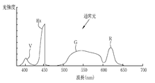
- the light source unit 20 includes a V-LED (VioletLightEmittingDiode) 20a, a B-LED (BlueLightEmittingDiode) 20b, a G-LED (GreenLightEmittingDiode) 20c, and an R-LED (Red). It has a 4-color LED of LightEmittingDiode) 20d and a wavelength cut filter 23. As shown in FIG. 3, the V-LED 20a emits purple light V having a wavelength band of 380 nm to 420 nm.
- the B-LED20b emits blue light B having a wavelength band of 420 nm to 500 nm.
- the blue light B emitted from the B-LED 23b at least the wavelength side longer than the peak wavelength of 450 nm is cut by the wavelength cut filter 23.
- the blue light Bx after passing through the wavelength cut filter 23 is in the wavelength range of 420 to 460 nm.
- the light in the wavelength region longer than 460 nm is cut because the light in the wavelength region longer than 460 nm reduces the vascular contrast of the blood vessel to be observed. Because there is.
- the wavelength cut filter 23 may dimming the light in the wavelength region longer than 460 nm instead of cutting the light in the wavelength region longer than 460 nm.
- the G-LED20c emits green light G having a wavelength band of 480 nm to 600 nm.
- the R-LED20d emits red light R having a wavelength band of 600 nm to 650 nm.
- the light emitted from each of the LEDs 20a to 20d may have the same center wavelength and the peak wavelength, or may be different from each other.
- the light source control unit 22 adjusts the emission timing, emission period, light amount, and spectral spectrum of the illumination light by independently controlling the lighting and extinguishing of the LEDs 20a to 20d and the amount of light emitted at the time of lighting.
- the control of turning on and off in the light source control unit 22 is different for each observation mode.
- the reference brightness can be set by the brightness setting unit of the light source device 14, the console 19, or the like.
- the light source control unit 22 lights all the V-LED20a, B-LED20b, G-LED20c, and R-LED20d.
- the peak of the light intensity of the blue light Bx is the purple light V, the green light G.
- red light R are set to be larger than the peak of any of the light intensities.
- the light source control unit 22 lights all the V-LED20a, B-LED20b, G-LED20c, and R-LED20d.
- the light intensity ratio Ls between the purple light V, the blue light B, the green light G, and the red light R has a peak of the light intensity of the purple light V, which is the blue light Bx and the green light G.
- red light R are set to be larger than the peak of any of the light intensities.
- the peaks of the light intensities of the green light G and the red light R are set to be smaller than the peaks of the light intensities of the purple light V and the blue light Bx.
- the light source device 14 emits multicolored light for the special mode including purple light V, blue light Bx, green light G, and red light R as special light.
- the special light is bluish because the proportion of purple light V is large.
- the special light does not have to include light of all four colors, and may include light from at least one of the four color LEDs 20a to 20d. Further, the special light preferably has a main wavelength range of 450 nm or less, for example, a peak wavelength or a center wavelength.
- the illumination light emitted by the light source unit 20 is incident on the light guide 24 inserted into the insertion unit 12a via an optical path coupling portion (not shown) formed by a mirror, a lens, or the like.
- the light guide 24 is built in the endoscope 12 and the universal cord, and propagates the illumination light to the tip portion 12d of the endoscope 12.
- the universal cord is a cord that connects the endoscope 12, the light source device 14, and the processor device 16.
- a multimode fiber can be used as the light guide 24.
- a fine fiber cable having a core diameter of 105 ⁇ m, a clad diameter of 125 ⁇ m, and a diameter of ⁇ 0.3 mm to ⁇ 0.5 mm including a protective layer serving as an outer skin can be used for the light guide 24.
- the tip portion 12d of the endoscope 12 is provided with an illumination optical system 30a and an imaging optical system 30b.
- the illumination optical system 30a has an illumination lens 32.
- the observation target is illuminated by the illumination light propagating through the illumination lens 32 and propagating through the light guide 24.
- the image pickup optical system 30b includes an objective lens 34, a magnifying optical system 36, and an image pickup sensor 38.
- Various types of light such as reflected light, scattered light, and fluorescence from the observation target are incident on the image pickup sensor 38 through the objective lens 34 and the magnifying optical system 36. As a result, an image to be observed is formed on the image sensor 38.
- the magnifying optical system 36 includes a zoom lens 36a that magnifies the observation target and a lens driving unit 36b that moves the zoom lens 36a in the optical axis direction CL.
- the zoom lens 36a is freely moved between the telephoto end and the wide-angle end according to the zoom control by the lens driving unit 36b, thereby enlarging or reducing the observation target imaged on the image sensor 38.
- the image sensor 38 is a color image sensor that captures an observation target irradiated with illumination light.
- Each pixel of the image sensor 38 is provided with any one of an R (red) color filter, a G (green) color filter, and a B (blue) color filter.
- the image pickup sensor 38 receives purple to blue light from the B pixel provided with the B color filter, receives green light from the G pixel provided with the G color filter, and is provided with the R color filter.
- the existing R pixel receives red light.
- the image signals of each RGB color are output from the pixels of each color.
- the image sensor 38 transmits the output image signal to the CDS circuit 40.
- the image sensor 38 In the normal mode or the region of interest mode, the image sensor 38 outputs a Bc image signal from the B pixel, outputs a Gc image signal from the G pixel, and outputs an R pixel by imaging an observation target illuminated with normal light. Outputs an Rc image signal from. Further, in the special mode, the image sensor 38 outputs a Bs image signal from the B pixel, outputs a Gs image signal from the G pixel, and Rs from the R pixel by imaging the observation target illuminated with the special light. Output the image signal.
- a CCD (Charge Coupled Device) image sensor, a CMOS (Complementary Metal-Oxide Semiconductor) image sensor, or the like can be used.
- a complementary color imaging sensor provided with complementary color filters of C (cyan), M (magenta), Y (yellow) and G (green) may be used. good.
- the image signals of four colors of CMYG are output. Therefore, by converting the image signals of the four colors of CMYG into the image signals of the three colors of RGB by the complementary color-primary color conversion, it is possible to obtain the image signals of each RGB color similar to the image sensor 38.
- a monochrome sensor without a color filter may be used.
- the CDS circuit 40 performs correlated double sampling (CDS: Correlated Double Sampling) on the analog image signal received from the image sensor 38.
- CDS Correlated Double Sampling
- the image signal that has passed through the CDS circuit 40 is input to the AGC circuit 42.
- the AGC circuit 40 performs automatic gain control (AGC: Automatic Gain Control) on the input image signal.
- a / D (Analog to Digital) conversion circuit 44 converts an analog image signal that has passed through the AGC circuit 42 into a digital image signal.
- the A / D conversion circuit 44 inputs the digital image signal after the A / D conversion to the processor device 16.
- the processor device 16 includes a control unit 46 that constitutes the processor of the present invention.
- the control unit 46 is a hardware resource for executing the program instructions stored in the memory 48, and drives and controls each unit of the endoscope system 10 to execute the program instructions.
- the processor device 16 includes the image signal acquisition unit 50, the DSP (Digital Signal Processor) 52, the noise reduction unit 54, the image processing unit 56, and the display control unit. Functions as 58.
- the image signal acquisition unit 50 drives and controls the endoscope 12 (imaging sensor 38, etc.) to perform imaging, and acquires an endoscope image (medical image).
- the image signal acquisition unit 50 sequentially acquires a plurality of endoscopic images by continuously imaging the observation target.
- the image signal acquisition unit 50 acquires an endoscopic image as a digital image signal corresponding to the observation mode. Specifically, in the case of the normal mode or the region of interest mode, the Bc image signal, the Gc image signal, and the Rc image signal are acquired. In the case of the special mode, the Bs image signal, the Gs image signal, and the Rs image signal are acquired.
- one frame of Bc image signal, Gc image signal, and Rc image signal is acquired when the normal light is illuminated
- one frame of Bs image signal, Gs image signal, and Rs is acquired when the special light is illuminated. Acquire an image signal.
- the DSP 52 performs various signal processing such as defect correction processing, offset processing, gain correction processing for DSP, linear matrix processing, gamma conversion processing, and demosaic processing on the image signal acquired by the image signal acquisition unit 50.
- the defect correction process corrects the signal of the defective pixel of the image sensor 38.
- the offset processing removes the dark current component from the defect-corrected image signal and sets an accurate zero level.
- the DSP gain correction process adjusts the signal level by multiplying the offset-processed image signal by a specific DSP gain.
- the linear matrix processing enhances the color reproducibility of the image signal that has been gain-corrected for DSP.
- the gamma conversion process adjusts the brightness and saturation of the image signal processed by the linear matrix.
- the gamma-converted image signal is subjected to demosaic processing (also referred to as isotropic processing or simultaneous processing) to generate a signal of a color lacking in each pixel by interpolation. By this demosaic processing, all the pixels have RGB signals of each color.
- the noise reduction unit 54 reduces noise by performing noise reduction processing by, for example, a moving average method, a median filter method, or the like on an image signal that has undergone demosaic processing or the like by DSP 52.
- the image signal after noise reduction is input to the image processing unit 56.
- the image processing unit 56 includes a normal mode image processing unit 60, a special mode image processing unit 62, and a region of interest mode image processing unit 64.
- the normal mode image processing unit 60 operates when the normal mode is set, and performs color conversion processing, color enhancement processing, and structure enhancement processing on the received Bc image signal, Gc image signal, and Rc image signal. conduct.
- the RGB image signal is subjected to color conversion processing by 3 ⁇ 3 matrix processing, gradation conversion processing, three-dimensional LUT (Look Up Table) processing, or the like.
- the color enhancement process is performed on the RGB image signal that has undergone the color conversion process.
- the structure enhancement process is a process for emphasizing the structure of the observation target, and is performed on the RGB image signal after the color enhancement process.
- a normal image can be obtained by performing various image processing and the like as described above. Since the normal image is an image obtained based on normal light in which purple light V, blue light Bx, green light G, and red light R are emitted in a well-balanced manner, it is an image having a natural hue.
- the special mode image processing unit 62 operates when the special mode is set.
- the special mode image processing unit 62 performs color conversion processing, color enhancement processing, and structure enhancement processing on the received Bs image signal, Gs image signal, and Rs image signal.
- the processing contents of the color conversion processing, the color enhancement processing, and the structure enhancement processing are the same as those of the normal mode image processing unit 60.
- a special image can be obtained by performing various image processing as described above.
- the special image is an image obtained based on special light in which purple light V, which has a high absorption coefficient of hemoglobin in blood vessels, emits more light than blue light Bx, green light G, and red light R of other colors. Therefore, the resolution of the vascular structure and the ductal structure is higher than that of other structures.
- the attention area mode image processing unit 64 operates when it is set in the attention area mode.
- the attention area mode image processing unit 64 performs the same image processing as the normal mode image processing unit 60 on the received Bc image signal, Gc image signal, and Rc image signal, such as color conversion processing.
- the attention area mode image processing unit 64 functions as the recognition processing unit 72 and the recognition result correction unit 73 by the drive control of the control unit 46 (see FIG. 2) accompanying the execution of the program instruction described above. do.
- the recognition processing unit 72 sequentially acquires endoscopic images by the same image processing as the normal mode image processing unit 60, analyzes the acquired endoscopic images, and performs recognition processing.
- the recognition process performed by the recognition processing unit 72 includes a detection process for detecting a region of interest from a recognition image (endoscopic image in the present embodiment) and a discrimination process for distinguishing the type of lesion included in the recognition image. And are included. Further, the discrimination process includes a process performed on the region of interest and a process performed on the entire recognition image.
- the recognition processing unit 72 performs detection processing for detecting a rectangular region including a lesion portion as a region of interest from an endoscopic image.
- the recognition processing unit 72 first divides the endoscopic image into a plurality of small areas, for example, a square area for several pixels. Next, the image feature amount is calculated from the divided endoscopic images. Subsequently, based on the calculated feature amount, it is determined whether or not each small region is a lesion. Finally, a group of small regions identified as the same type is extracted as one lesion, and a rectangular region including the extracted lesion is detected as a region of interest.
- a machine learning algorithm such as a convolutional neural network or deep learning is preferable.
- the feature amount calculated from the endoscopic image by the recognition processing unit 72 is preferably an index value obtained from the shape and color of a predetermined portion in the observation target or those shapes and colors.
- an index value obtained from the shape and color of a predetermined portion in the observation target or those shapes and colors.
- the value is at least one of the length, the degree of tortuosity of the blood vessel, and the color information, or a combination of two or more of them.
- the recognition result correction unit 73 performs the recognition result correction process for correcting the recognition process result performed by the recognition processing unit 72.
- the recognition result correction process will be described.
- the endoscopic image obtained from which the recognition process result to be the target of the recognition result correction process is obtained is referred to as a specific image 80 (specific medical image) (FIG. 8).
- the position information of the attention region 82ROI of the pre-image 82 (medical image for comparison) acquired (imaged) before the specific image 80 and the specific image 80 are used.
- the position information of the attention region 80ROI of the specific image 80 is corrected by using the position information of the attention region 84ROI of the image 84 (medical image for comparison) after being acquired (imaged) later.
- the front image 82 is an endoscopic image acquired (captured) at the time “t ⁇ ” when the time when the specific image 80 was acquired (captured) is “t”.
- the value of " ⁇ ” can be set as appropriate, in the present embodiment, the value of " ⁇ ” is set so that the image acquired (captured) immediately before the specific image 80 becomes the front image 82. That is, for example, when an image is taken at a cycle of 60 times per second (frame) to acquire an endoscopic image, " ⁇ " is set to "1/60 (second)".
- the rear image 84 is an endoscopic image acquired (captured) at the time "t + ⁇ " when the time when the specific image 80 was acquired (captured) is "t".
- the value of " ⁇ ” can be set as appropriate, in the present embodiment, the value of " ⁇ ” is set so that the image acquired (captured) immediately after the specific image 80 becomes the front image 82. That is, for example, when an image is taken at a cycle of 60 times per second (frame) to acquire an endoscopic image, " ⁇ " is set to "1/60 (second)".
- the specific image so that the intermediate position between the center of the attention region 82ROI of the front image 82 and the center of the attention region 84ROI of the rear image 84 coincides with the center of the attention region 80ROI of the specific image 80.
- the position (position information) of the area of interest 80ROI of 80 is changed (corrected). That is, the position information of the attention region 80ROI of the specific image 80 is corrected by using the linear sum of the position information of the attention regions 82ROI and 84ROI of the front image 82 and the rear image 84.
- the normal image generated by the normal mode image processing unit 60, the special image generated by the special mode image processing unit 62, and the processing result performed by the attention area mode image processing unit 64 (recognition processing).
- the result and the result of the recognition result correction process) are input to the display control unit 58.
- the display control unit 58 generates a display screen using the input information and outputs and displays it on the monitor 18.
- the normal image, the special image, and the processing result may be stored in the memory 48 or the like instead of or in addition to being output and displayed on the monitor 18.
- the feature amount used for the recognition process and / or the processing algorithm of the recognition process is not changed, and the recognition process is not performed again after such a change.
- the recognition processing result of the specific image 80 is corrected by using the recognition processing result of the above and the recognition processing result of the rear image 84.
- a more accurate recognition processing result can be obtained while reducing the processing load as compared with the case where the feature amount used for the recognition processing and / or the algorithm of the recognition processing is changed or the re-recognition processing is performed. be able to.
- the position (center position) of the attention region 80ROI of the specific image 80 is changed (see FIG. 8), but the size of the attention region 80ROI of the specific image 80 is changed. You may change it.
- the size of the attention area 80ROI of the specific image 80 is the average size (area) of the size (area) of the attention area 82ROI of the front image 82 and the size (area) of the attention area 84ROI of the rear image 84. Can be changed (enlarged or reduced).
- the intermediate position between the upper right corner of the attention area 82ROI of the front image 82 and the upper right corner of the attention area 84ROI of the rear image 84 becomes the upper right corner of the attention area 80ROI of the specific image 80, and the lower right corner of the attention area 80ROI.
- the intermediate position between the corner and the lower right corner of the attention area 84ROI is the lower right corner of the attention area 80ROI, and the intermediate position between the upper left corner of the attention area 82ROI and the upper left corner of the attention area 84ROI is the upper left corner of the attention area 80ROI.
- the size and center position of the region of interest 80ROI may be changed so that the intermediate position between the lower left corner of the region of interest 82ROI and the lower left corner of the region of interest 84ROI is the lower left corner of the region of interest 80ROI. ..
- the medical image for comparison pre-image 82 and rear image 84 in the first embodiment
- there may be a lesion portion that does not exist in the specific image 80 and such a comparative image is used.
- an appropriate correction cannot be performed. Therefore, it is preferable to correct the recognition result of the specific image 80 by using only the medical image for comparison in which the position of the region of interest is within a predetermined range from the position of the region of interest 80ROI of the specific image 80. By doing so, appropriate correction is performed, and a more accurate recognition processing result can be obtained.
- the recognition processing unit 72 detects the lesion portion from the specific image 80 as in the first embodiment, and further performs a discrimination process for discriminating the type of lesion or the like from the detected lesion portion, or the specific image. Discrimination processing is performed on the entire 80. Then, the recognition result correction unit 73 corrects the discrimination result of the specific image 80 by using the discrimination result of the front image 82 and the discrimination result of the rear image 84.
- the differentiation result of the attention region 82ROI of the front image 82 is “tumor”
- the differentiation result of the attention region 80ROI of the specific image 80 is “non-tumor”
- the differentiation result of the attention region 84ROI of the rear image 84 is “tumor”.
- the discrimination result of is "tumor”
- the discrimination result of the region of interest 80ROI of the specific image 80 is changed (corrected) to "tumor”. That is, among the numbers of the discrimination results of the front image 82 and the rear image 84 for each type, the discrimination result of the specific image 80 is corrected to the largest number of discrimination results (for each type of the discrimination result of the medical image for comparison). The number is used to correct the discrimination result of the specific image 80).
- AI Artificial Intelligence
- Convolutional neural network Convolutional Neural Network
- template matching texture analysis, frequency analysis, or the like. ..
- the recognition processing result of the specific image 80 is corrected by using the recognition processing result of one front image 82 and the recognition processing result of one rear image 84. Not limited. For example, as shown in FIGS. 10 and 11, even if the recognition processing result of the specific image 80 is corrected by using the recognition processing result of the plurality of front images 82 and the recognition processing result of the plurality of rear images 84. good.
- the recognition processing result of the specific image 80 is corrected by using the recognition processing result of the two front images 82 and the recognition processing result of the two rear images 84.
- the average position of the center position of the attention region 82ROI of the two front images 82 and the center position of the attention region 84ROI of the two rear images 84 is calculated, and the calculated position is The center position of the attention region 80ROI is corrected so as to be the center position of the attention region 80ROI of the specific image 80.
- the discrimination result of the specific image 80 is corrected to “tumor”, which is the most common discrimination result among the discrimination result of the two front images 82 and the discrimination result of the two rear images 84. ing.
- the recognition processing result of the specific image 80 may be corrected by using three or more front images 82 and rear images 84.
- the recognition processing result of the specific image 80 is corrected by using both the front image 82 and the rear image 84
- the recognition of the specific image 80 is performed by using only one of the front image 82 and the rear image 84.
- the processing result may be corrected.
- FIG. 10 when the recognition result of the specific image 80 is corrected using only the front image 82, the movement amount and the movement direction of the center of the attention region 82 ROI per unit time are compared by comparing the two front images 82.
- the position of the center of the region of interest 80ROI of the specific image 80 may be corrected by using the calculated movement amount and movement direction.
- FIG. 11 when the recognition result of the specific image 80 is corrected using only the front image 82, the specific image 80 is divided into the most types of the discrimination results of the two front images 82.
- the discrimination result may be corrected.
- the recognition result correction process may be performed.
- the recognition processing unit 72 executes the recognition process, calculates the certainty of the executed recognition process, and notifies the recognition result correction unit 73. Then, the recognition result correction unit 73 performs the recognition result correction process when the certainty of the result of the recognition process is less than a predetermined threshold value.
- the recognition processing result may be corrected when the user specifies it.
- the endoscope image acquired by the attention area mode image processing unit 64 or the recognition processing result performed by the recognition processing unit 72 is displayed on the monitor 18, and the user operates the console 19 while observing the monitor 18. Therefore, the target (endoscopic image or recognition processing result) to be subjected to the recognition result correction processing may be specified.
- the still image acquisition unit 13b is operated, it is considered that the user has specified the endoscopic image acquired by the operation of the still image acquisition unit 13b, and the recognition result correction processing may be performed.
- the recognition processing result correction processing is performed according to the user's designation
- what is required for the recognition processing result correction processing is the result of the recognition processing of the front image 82 and / or the rear image 84. Therefore, the recognition process for the endoscopic image other than this may be omitted.
- the processor device 16 which is a part of the endoscope system 10 functions as the processor of the present invention, that is, the control unit 46 which is the processor of the present invention is the endoscope system 10 (processor device 16).
- the endoscopic system 10 has been described as an example of functioning as the region of interest mode image processing unit 64, but the present invention is not limited thereto.
- an image processing device 110 is provided separately from the endoscope system 100, and the image processing device 110 is provided with a control unit 46 and a memory 48, and the image processing device 110 is provided.
- the configuration may be configured to function as the attention area mode image processing unit 64.
- the image processing device 110 is connected to the endoscope system 100, and an endoscope image is transmitted from the endoscope system 100 to the image processing device 110.
- the attention area mode image processing unit 64 performs the above-mentioned recognition processing and recognition result correction processing, and notifies the result of the recognition processing and recognition result correction processing to a predetermined notification destination (endoscope in the example of FIG. 14). Send to system 100).
- the above-mentioned image processing device 110 is connected to a device or system for acquiring a medical image other than the endoscopic image, and the medical image other than the endoscopic image is recognized and the recognition result is corrected. It may be configured as a processing system. Medical images other than endoscopy include ultrasonic images obtained by an ultrasonic diagnostic apparatus, X-ray images obtained by an X-ray inspection apparatus, CT images obtained by a CT (Computed Tomography) inspection apparatus, and MRI (Magnetic Resonance Imaging). ) MRI inspection image obtained by the inspection device and the like can be mentioned.
- the control unit 46 (processor) of the present invention includes a CPU (Central Processing Unit), a GPU (Graphical Processing Unit), which are general-purpose processors that function as various processing units such as the attention area mode image processing unit 64. FPGA (Field Programmable Gate Array) etc. are included. Further, the control unit 46 (processor) of the present invention includes not only a programmable logic device (Programmable Logic Device: PLD), which is a processor whose circuit configuration can be changed after manufacturing, such as a CPU, GPU, and FPGA, but also various types. It also includes a dedicated electric circuit, which is a processor having a circuit configuration designed exclusively for executing processing.
- PLD programmable logic device
- One processing unit may be composed of one of these various processors, or a combination of two or more processors of the same type or different types (for example, a plurality of FPGAs, a combination of a CPU and an FPGA, or a CPU. And GPU, etc.). Further, a plurality of processing units may be configured by one processor. As an example of configuring a plurality of processing units with one processor, first, as represented by a computer such as a client or a server, one processor is configured by a combination of one or more CPUs and software. There is a form in which this processor functions as a plurality of processing units.
- SoC System On Chip
- a processor that realizes the functions of the entire system including a plurality of processing units with one IC (Integrated Circuit) chip is used.
- the various processing units are configured by using one or more of the above-mentioned various processors as a hardware-like structure.
Abstract
Provided are: a medical image processing system capable of obtaining more accurate recognition results while reducing processing loads; and a method for operating the medical image processing system. An endoscope system (10) sequentially acquires multiple endoscope images by continuously imaging an object to be observed. A recognition processing unit (72) detects, as an attention region, a region including a lesion from the acquired endoscope image. A recognition result correction unit (73) corrects the position of an attention region (80ROI) of a specific image (80) using the position of an attention region (82ROI) of an anterior image (82) acquired anterior to the specific image (80) and the position of an attention region (84ROI) of a posterior image (84) acquired posterior to the specific image (80).
Description
本発明は、医用画像処理システム、医用画像処理システムの作動方法に関する。
The present invention relates to a medical image processing system and a method of operating a medical image processing system.
医療分野においては、内視鏡画像、X線画像、CT(Computed Tomography)画像、MR(Magnetic Resonanse)画像などの医用画像を用いて、患者の病状の診断や経過観察などの画像診断が行われている。このような画像診断に基づいて、医師などは治療方針の決定などを行っている。
In the medical field, medical images such as endoscopic images, X-ray images, CT (Computed Tomography) images, and MR (Magnetic Resonanse) images are used to diagnose the patient's medical condition and perform diagnostic imaging such as follow-up. ing. Based on such diagnostic imaging, doctors and the like make decisions on treatment policies.
近年、医用画像を用いた画像診断においては、臓器内の病変や腫瘍など注意して観察すべき注目領域を、医用画像処理装置によって認識処理することが行われつつある。特に、ディープラーニングなどの機械学習の手法は、認識処理の能力や効率の向上に寄与している。
In recent years, in image diagnosis using medical images, areas of interest such as lesions and tumors in organs that should be carefully observed are recognized and processed by a medical image processing device. In particular, machine learning methods such as deep learning contribute to improving the ability and efficiency of recognition processing.
一方、医用画像処理装置によって行われた認識処理の結果は必ずしも完全なものではない。このため、下記特許文献1では、連続した撮影により順次取得された複数の医用画像の各々について認識処理を行って画像の特徴量を算出するとともに、認識処理を行った画像の前後に撮影された医用画像を用いて、認識処理において算出した特徴量の補正をし、補正した特徴量を用いて再度認識処理を行う構成が記載されている。
On the other hand, the result of the recognition process performed by the medical image processing device is not always perfect. Therefore, in Patent Document 1 below, recognition processing is performed on each of a plurality of medical images sequentially acquired by continuous imaging to calculate the feature amount of the image, and images are taken before and after the image on which the recognition processing is performed. A configuration is described in which the feature amount calculated in the recognition process is corrected using a medical image, and the recognition process is performed again using the corrected feature amount.
上記特許文献1では、特徴量の補正と再認識処理とを行うことで、より精度の高い認識結果を得られる反面、認識結果を得るための処理負荷が大きいといった問題があった。
In Patent Document 1, the feature amount is corrected and the re-recognition process is performed to obtain a more accurate recognition result, but there is a problem that the processing load for obtaining the recognition result is large.
本発明は、上記背景を鑑みてなされたものであり、処理負荷を軽減しながらより精度の高い認識結果を得ることが可能な医用画像処理システム、医用画像処理システムの作動方法を提供することを目的としている。
The present invention has been made in view of the above background, and provides an operation method of a medical image processing system and a medical image processing system capable of obtaining more accurate recognition results while reducing the processing load. I am aiming.
上記目的を達成するために、本発明の医用画像処理システムは、プログラム命令を記憶するメモリと、プログラム命令を実行させるプロセッサと、を備えた医用画像処理システムにおいて、プロセッサは、観察対象を連続して撮像することにより生成された複数の医用画像を順次取得し、複数の医用画像の各々に対して認識処理を行うことにより、医用画像から注目領域を検出し、複数の医用画像のうちの特定の医用画像に対して行われた認識処理で検出した注目領域の位置情報を、特定の医用画像の前後の少なくとも一方に撮像された比較用の医用画像に対して行われた認識処理で検出した注目領域の位置情報を用いて補正する。
In order to achieve the above object, the medical image processing system of the present invention is a medical image processing system including a memory for storing a program instruction and a processor for executing the program instruction, in which the processor continuously observes an observation target. By sequentially acquiring a plurality of medical images generated by imaging and performing recognition processing on each of the plurality of medical images, a region of interest is detected from the medical images and the identification of the plurality of medical images is performed. The position information of the region of interest detected by the recognition process performed on the medical image of the above was detected by the recognition process performed on the comparison medical image captured at least one before and after the specific medical image. Correct using the position information of the area of interest.
補正は、認識処理の結果の確信度が所定の閾値を下回る場合に行われるものでもよい。
The correction may be performed when the certainty of the result of the recognition process falls below a predetermined threshold value.
補正は、ユーザーが指示した場合に行われるものでもよい。
The correction may be performed when the user instructs it.
補正では、比較用の医用画像の注目領域の位置情報の線形和を用いてもよい。
In the correction, the linear sum of the position information of the region of interest of the medical image for comparison may be used.
補正では、比較用の医用画像の注目領域のうち、特定の医用画像の注目領域から所定範囲内に位置する注目領域の位置情報を用いてもよい。
In the correction, the position information of the attention area located within a predetermined range from the attention area of the specific medical image among the attention areas of the medical image for comparison may be used.
認識処理には、注目領域を鑑別する鑑別処理が含まれていてもよい。
The recognition process may include a discrimination process for discriminating the region of interest.
補正では、鑑別の結果の補正を行ってもよい。
In the correction, the result of discrimination may be corrected.
鑑別の結果の補正では、比較用の医用画像の鑑別の結果の種類毎の数を用いてもよい。
In the correction of the discrimination result, the number for each type of the discrimination result of the medical image for comparison may be used.
認識処理では、Convolutional Neural Networkを用いてもよい。
In the recognition process, Convolutional Neural Network may be used.
医用画像は、内視鏡から得られた画像であってもよい。
The medical image may be an image obtained from an endoscope.
また、上記目的を達成するために、本発明の医用画像処理システムの作動方法は、プログラム命令を記憶するメモリと、プログラム命令を実行させるプロセッサと、を備えた医用画像処理システムの作動方法において、プロセッサは、観察対象を連続して撮像することにより生成された複数の医用画像を順次取得し、複数の医用画像の各々に対して認識処理を行うことにより、医用画像から注目領域を検出し、複数の医用画像のうちの特定の医用画像に対して行われた認識処理で検出した注目領域の位置情報を、特定の医用画像の前後の少なくとも一方に撮像された比較用の医用画像に対して行われた認識処理で検出した注目領域の位置情報を用いて補正する。
Further, in order to achieve the above object, the method of operating the medical image processing system of the present invention is the method of operating the medical image processing system including a memory for storing program instructions and a processor for executing the program instructions. The processor sequentially acquires a plurality of medical images generated by continuously capturing an observation target, and performs recognition processing on each of the plurality of medical images to detect a region of interest from the medical images. The position information of the region of interest detected by the recognition process performed on a specific medical image among a plurality of medical images is applied to a comparative medical image captured at least one before and after the specific medical image. Correction is performed using the position information of the region of interest detected by the recognized recognition process.
本発明によれば、処理負荷を軽減しながらより精度の高い認識結果を得ることが可能な医用画像処理システム、医用画像処理システムの作動方法を提供できる。
According to the present invention, it is possible to provide a medical image processing system and a method of operating a medical image processing system that can obtain more accurate recognition results while reducing the processing load.
[第1実施形態]
図1に示すように、内視鏡システム10(医用画像処理システム)は、内視鏡12と、光源装置14と、プロセッサ装置16と、モニタ18と、コンソール19とを有する。内視鏡12は、光源装置14と光学的に接続し、かつ、プロセッサ装置16と電気的に接続する。内視鏡12は、被検体内に挿入する挿入部12aと、挿入部12aの基端部分に設けた操作部12bと、挿入部12aの先端側に設けた湾曲部12c及び先端部12dを有している。操作部12bのアングルノブ13aを操作することにより、湾曲部12cが湾曲動作する。この湾曲動作によって、先端部12dが所望の方向に向けられる。 [First Embodiment]
As shown in FIG. 1, the endoscope system 10 (medical image processing system) includes anendoscope 12, a light source device 14, a processor device 16, a monitor 18, and a console 19. The endoscope 12 is optically connected to the light source device 14 and electrically connected to the processor device 16. The endoscope 12 has an insertion portion 12a to be inserted into the subject, an operation portion 12b provided at the base end portion of the insertion portion 12a, and a curved portion 12c and a tip portion 12d provided on the tip end side of the insertion portion 12a. doing. By operating the angle knob 13a of the operation unit 12b, the bending unit 12c bends. This bending motion directs the tip 12d in a desired direction.
図1に示すように、内視鏡システム10(医用画像処理システム)は、内視鏡12と、光源装置14と、プロセッサ装置16と、モニタ18と、コンソール19とを有する。内視鏡12は、光源装置14と光学的に接続し、かつ、プロセッサ装置16と電気的に接続する。内視鏡12は、被検体内に挿入する挿入部12aと、挿入部12aの基端部分に設けた操作部12bと、挿入部12aの先端側に設けた湾曲部12c及び先端部12dを有している。操作部12bのアングルノブ13aを操作することにより、湾曲部12cが湾曲動作する。この湾曲動作によって、先端部12dが所望の方向に向けられる。 [First Embodiment]
As shown in FIG. 1, the endoscope system 10 (medical image processing system) includes an
また、操作部12bには、アングルノブ13aの他、静止画像の取得操作に用いる静止画像取得部13b、観察モードの切り替え操作に用いるモード切替部13c、ズーム倍率の変更操作に用いるズーム操作部13dを設けている。静止画像取得部13bは、モニタ18に観察対象の静止画像を表示するフリーズ操作と、ストレージに静止画像を保存するレリーズ操作が可能である。
In addition to the angle knob 13a, the operation unit 12b includes a still image acquisition unit 13b used for still image acquisition operation, a mode switching unit 13c used for observation mode switching operation, and a zoom operation unit 13d used for zoom magnification changing operation. Is provided. The still image acquisition unit 13b can perform a freeze operation for displaying the still image to be observed on the monitor 18 and a release operation for saving the still image in the storage.
内視鏡システム10は、観察モードとして、通常モードと、特殊モードと、注目領域モードとを有している。観察モードが通常モードである場合、複数色の光を通常モード用の光量比Lcで合波した通常光を発光する。また、観察モードが特殊モードである場合、複数色の光を特殊モード用の光量比Lsで合波した特殊光を発光する。
The endoscope system 10 has a normal mode, a special mode, and a region of interest mode as observation modes. When the observation mode is the normal mode, the normal light obtained by combining the light of a plurality of colors with the light amount ratio Lc for the normal mode is emitted. Further, when the observation mode is the special mode, the special light obtained by combining the light of a plurality of colors with the light amount ratio Ls for the special mode is emitted.
また、観察モードが注目領域モードである場合、注目領域モード用照明光を発光する。本実施形態では、注目領域モード用照明光として、通常光を発光するが、特殊光を発光するようにしてもよい。
Also, when the observation mode is the attention area mode, the illumination light for the attention area mode is emitted. In the present embodiment, normal light is emitted as the illumination light for the region of interest mode, but special light may be emitted.
プロセッサ装置16は、モニタ18及びコンソール19と電気的に接続する。モニタ18は、観察対象の画像や、画像に付帯する情報等を出力表示する。コンソール19は、注目領域(ROI:Region Of Interest)の指定、認識処理を行う画像の指定、認識結果補正処理を行う画像または認識処理結果の指定、機能設定などの入力操作を受け付けるユーザインタフェースとして機能する。
The processor device 16 is electrically connected to the monitor 18 and the console 19. The monitor 18 outputs and displays an image to be observed, information incidental to the image, and the like. The console 19 functions as a user interface that accepts input operations such as specifying a region of interest (ROI: RegionOfInterest), specifying an image to perform recognition processing, specifying an image to perform recognition result correction processing or a recognition processing result, and setting functions. do.
図2に示すように、光源装置14は、観察対象の照明に用いる照明光を発する光源部20と、光源部20を制御する光源制御部22とを備えている。光源部20は、複数色のLED(Light Emitting Diode)等の半導体光源である。光源制御部22は、LED等のオン/オフや、LED等の駆動電流や駆動電圧の調整によって、照明光の発光量を制御する。また、光源制御部22は、光学フィルタの変更等によって、照明光の波長帯域を制御する。
As shown in FIG. 2, the light source device 14 includes a light source unit 20 that emits illumination light used for illuminating an observation target, and a light source control unit 22 that controls the light source unit 20. The light source unit 20 is a semiconductor light source such as a multi-color LED (Light Emitting Diode). The light source control unit 22 controls the amount of light emitted from the illumination light by turning on / off the LED and the like, and adjusting the drive current and the drive voltage of the LED and the like. Further, the light source control unit 22 controls the wavelength band of the illumination light by changing the optical filter or the like.
第1実施形態では、光源部20は、V-LED(Violet Light Emitting Diode)20a、B-LED(Blue Light Emitting Diode)20b、G-LED(Green Light Emitting Diode)20c、及びR-LED(Red Light Emitting Diode)20dの4色のLEDと、波長カットフィルタ23とを有している。図3に示すように、V-LED20aは、波長帯域380nm~420nmの紫色光Vを発する。
In the first embodiment, the light source unit 20 includes a V-LED (VioletLightEmittingDiode) 20a, a B-LED (BlueLightEmittingDiode) 20b, a G-LED (GreenLightEmittingDiode) 20c, and an R-LED (Red). It has a 4-color LED of LightEmittingDiode) 20d and a wavelength cut filter 23. As shown in FIG. 3, the V-LED 20a emits purple light V having a wavelength band of 380 nm to 420 nm.
B-LED20bは、波長帯域420nm~500nmの青色光Bを発する。B-LED23bから出射した青色光Bのうち少なくともピーク波長の450nmよりも長波長側は、波長カットフィルタ23によりカットされる。これにより、波長カットフィルタ23を透過した後の青色光Bxは、420~460nmの波長範囲になる。このように、460nmよりも長波長側の波長域の光をカットしているのは、この460nmよりも長波長側の波長域の光は、観察対象である血管の血管コントラストを低下させる要因であるためである。なお、波長カットフィルタ23は、460nmよりも長波長側の波長域の光をカットする代わりに、460nmよりも長波長側の波長域の光を減光させてもよい。
The B-LED20b emits blue light B having a wavelength band of 420 nm to 500 nm. Of the blue light B emitted from the B-LED 23b, at least the wavelength side longer than the peak wavelength of 450 nm is cut by the wavelength cut filter 23. As a result, the blue light Bx after passing through the wavelength cut filter 23 is in the wavelength range of 420 to 460 nm. In this way, the light in the wavelength region longer than 460 nm is cut because the light in the wavelength region longer than 460 nm reduces the vascular contrast of the blood vessel to be observed. Because there is. The wavelength cut filter 23 may dimming the light in the wavelength region longer than 460 nm instead of cutting the light in the wavelength region longer than 460 nm.
G-LED20cは、波長帯域が480nm~600nmに及ぶ緑色光Gを発する。R-LED20dは、波長帯域が600nm~650nmに及び赤色光Rを発する。なお、各LED20a~20dから発せられる光は、それぞれの中心波長とピーク波長とが同じであっても良いし、異なっていても良い。
The G-LED20c emits green light G having a wavelength band of 480 nm to 600 nm. The R-LED20d emits red light R having a wavelength band of 600 nm to 650 nm. The light emitted from each of the LEDs 20a to 20d may have the same center wavelength and the peak wavelength, or may be different from each other.
光源制御部22は、各LED20a~20dの点灯や消灯、及び点灯時の発光量等を独立に制御することによって、照明光の発光タイミング、発光期間、光量、及び分光スペクトルの調節を行う。光源制御部22における点灯及び消灯の制御は、観察モードごとに異なっている。なお、基準の明るさは光源装置14の明るさ設定部又はコンソール19等によって設定可能である。
The light source control unit 22 adjusts the emission timing, emission period, light amount, and spectral spectrum of the illumination light by independently controlling the lighting and extinguishing of the LEDs 20a to 20d and the amount of light emitted at the time of lighting. The control of turning on and off in the light source control unit 22 is different for each observation mode. The reference brightness can be set by the brightness setting unit of the light source device 14, the console 19, or the like.
通常モード又は注目領域モードの場合、光源制御部22は、V-LED20a、B-LED20b、G-LED20c、及びR-LED20dを全て点灯させる。その際、図4に示すように、紫色光V、青色光B、緑色光G、及び赤色光R間の光量比Lcは、青色光Bxの光強度のピークが、紫色光V、緑色光G、及び赤色光Rのいずれの光強度のピークよりも大きくなるように、設定されている。これにより、通常モード又は注目領域モードでは、光源装置14から、紫色光V、青色光Bx、緑色光G、及び赤色光Rを含む通常モード用又は注目領域モード用の多色光が、通常光として、が発せられる。通常光は、青色帯域から赤色帯域まで一定以上の強度を有しているため、ほぼ白色となっている。
In the normal mode or the attention area mode, the light source control unit 22 lights all the V-LED20a, B-LED20b, G-LED20c, and R-LED20d. At that time, as shown in FIG. 4, as for the light amount ratio Lc between the purple light V, the blue light B, the green light G, and the red light R, the peak of the light intensity of the blue light Bx is the purple light V, the green light G. , And red light R are set to be larger than the peak of any of the light intensities. As a result, in the normal mode or the region of interest mode, the multicolored light for the normal mode or the region of interest including the purple light V, the blue light Bx, the green light G, and the red light R is used as the normal light from the light source device 14. , Is emitted. Normal light is almost white because it has a certain intensity or more from the blue band to the red band.
特殊モードの場合、光源制御部22は、V-LED20a、B-LED20b、G-LED20c、及びR-LED20dを全て点灯させる。その際、図5に示すように、紫色光V、青色光B、緑色光G、及び赤色光R間の光量比Lsは、紫色光Vの光強度のピークが、青色光Bx、緑色光G、及び赤色光Rのいずれの光強度のピークよりも大きくなるように、設定されている。また、緑色光G及び赤色光Rの光強度のピークは、紫色光V及び青色光Bxの光強度のピークよりも小さくなるように、設定されている。これにより、特殊モードでは、光源装置14から、紫色光V、青色光Bx、緑色光G、及び赤色光Rを含む特殊モード用の多色光が、特殊光として発せられる。特殊光は、紫色光Vが占める割合が大きいことから、青みを帯びた光となっている。なお、特殊光は、4色全ての光が含まれていなくてもよく、4色のLED20a~20dのうち少なくとも1色のLEDからの光が含まれていればよい。また、特殊光は、450nm以下に主な波長域、例えばピーク波長又は中心波長を有することが好ましい。
In the special mode, the light source control unit 22 lights all the V-LED20a, B-LED20b, G-LED20c, and R-LED20d. At that time, as shown in FIG. 5, the light intensity ratio Ls between the purple light V, the blue light B, the green light G, and the red light R has a peak of the light intensity of the purple light V, which is the blue light Bx and the green light G. , And red light R are set to be larger than the peak of any of the light intensities. Further, the peaks of the light intensities of the green light G and the red light R are set to be smaller than the peaks of the light intensities of the purple light V and the blue light Bx. As a result, in the special mode, the light source device 14 emits multicolored light for the special mode including purple light V, blue light Bx, green light G, and red light R as special light. The special light is bluish because the proportion of purple light V is large. The special light does not have to include light of all four colors, and may include light from at least one of the four color LEDs 20a to 20d. Further, the special light preferably has a main wavelength range of 450 nm or less, for example, a peak wavelength or a center wavelength.
図2に戻り、光源部20が発した照明光は、ミラーやレンズ等で形成される光路結合部(図示しない)を介して、挿入部12a内に挿通したライトガイド24に入射する。ライトガイド24は、内視鏡12及びユニバーサルコードに内蔵され、照明光を内視鏡12の先端部12dまで伝搬する。ユニバーサルコードは、内視鏡12と光源装置14及びプロセッサ装置16とを接続するコードである。なお、ライトガイド24としては、マルチモードファイバを使用することができる。一例として、ライトガイド24には、コア径105μm、クラッド径125μm、外皮となる保護層を含めた径がφ0.3mm~φ0.5mmの細径なファイバケーブルを使用することができる。
Returning to FIG. 2, the illumination light emitted by the light source unit 20 is incident on the light guide 24 inserted into the insertion unit 12a via an optical path coupling portion (not shown) formed by a mirror, a lens, or the like. The light guide 24 is built in the endoscope 12 and the universal cord, and propagates the illumination light to the tip portion 12d of the endoscope 12. The universal cord is a cord that connects the endoscope 12, the light source device 14, and the processor device 16. A multimode fiber can be used as the light guide 24. As an example, a fine fiber cable having a core diameter of 105 μm, a clad diameter of 125 μm, and a diameter of φ0.3 mm to φ0.5 mm including a protective layer serving as an outer skin can be used for the light guide 24.
内視鏡12の先端部12dには、照明光学系30aと撮像光学系30bとを設けている。照明光学系30aは、照明レンズ32を有している。この照明レンズ32を介して、ライトガイド24を伝搬した照明光によって観察対象を照明する。撮像光学系30bは、対物レンズ34と、拡大光学系36と、撮像センサ38とを有している。これら対物レンズ34及び拡大光学系36を介して、観察対象からの反射光、散乱光、及び蛍光等の各種の光が撮像センサ38に入射する。これにより、撮像センサ38に観察対象の像が結像する。
The tip portion 12d of the endoscope 12 is provided with an illumination optical system 30a and an imaging optical system 30b. The illumination optical system 30a has an illumination lens 32. The observation target is illuminated by the illumination light propagating through the illumination lens 32 and propagating through the light guide 24. The image pickup optical system 30b includes an objective lens 34, a magnifying optical system 36, and an image pickup sensor 38. Various types of light such as reflected light, scattered light, and fluorescence from the observation target are incident on the image pickup sensor 38 through the objective lens 34 and the magnifying optical system 36. As a result, an image to be observed is formed on the image sensor 38.
拡大光学系36は、観察対象を拡大するズームレンズ36aと、ズームレンズ36aを光軸方向CLに移動させるレンズ駆動部36bとを備えている。ズームレンズ36aは、レンズ駆動部36bによるズーム制御に従って、テレ端とワイド端の間で自在に移動させることで、撮像センサ38に結像する観察対象を拡大又は縮小させる。
The magnifying optical system 36 includes a zoom lens 36a that magnifies the observation target and a lens driving unit 36b that moves the zoom lens 36a in the optical axis direction CL. The zoom lens 36a is freely moved between the telephoto end and the wide-angle end according to the zoom control by the lens driving unit 36b, thereby enlarging or reducing the observation target imaged on the image sensor 38.
撮像センサ38は、照明光が照射された観察対象を撮像するカラー撮像センサである。撮像センサ38の各画素には、R(赤色)カラーフィルタ、G(緑色)カラーフィルタ、B(青色)カラーフィルタのいずれかが設けられている。撮像センサ38は、Bカラーフィルタが設けられているB画素で紫色から青色の光を受光し、Gカラーフィルタが設けられているG画素で緑色の光を受光し、Rカラーフィルタが設けられているR画素で赤色の光を受光する。そして、各色の画素から、RGB各色の画像信号を出力する。撮像センサ38は、出力した画像信号を、CDS回路40に送信する。
The image sensor 38 is a color image sensor that captures an observation target irradiated with illumination light. Each pixel of the image sensor 38 is provided with any one of an R (red) color filter, a G (green) color filter, and a B (blue) color filter. The image pickup sensor 38 receives purple to blue light from the B pixel provided with the B color filter, receives green light from the G pixel provided with the G color filter, and is provided with the R color filter. The existing R pixel receives red light. Then, the image signals of each RGB color are output from the pixels of each color. The image sensor 38 transmits the output image signal to the CDS circuit 40.
通常モード又は注目領域モードにおいては、撮像センサ38は、通常光が照明された観察対象を撮像することにより、B画素からBc画像信号を出力し、G画素からGc画像信号を出力し、R画素からRc画像信号を出力する。また、特殊モードにおいては、撮像センサ38は、特殊光が照明された観察対象を撮像することにより、B画素からBs画像信号を出力し、G画素からGs画像信号を出力し、R画素からRs画像信号を出力する。
In the normal mode or the region of interest mode, the image sensor 38 outputs a Bc image signal from the B pixel, outputs a Gc image signal from the G pixel, and outputs an R pixel by imaging an observation target illuminated with normal light. Outputs an Rc image signal from. Further, in the special mode, the image sensor 38 outputs a Bs image signal from the B pixel, outputs a Gs image signal from the G pixel, and Rs from the R pixel by imaging the observation target illuminated with the special light. Output the image signal.
撮像センサ38としては、CCD(Charge Coupled Device)撮像センサやCMOS(Complementary Metal-Oxide Semiconductor)撮像センサ等を利用可能である。また、RGBの原色のカラーフィルタを設けた撮像センサ38の代わりに、C(シアン)、M(マゼンタ)、Y(イエロー)及びG(緑)の補色フィルタを備えた補色撮像センサを用いても良い。補色撮像センサを用いる場合には、CMYGの4色の画像信号を出力する。このため、補色-原色色変換によって、CMYGの4色の画像信号をRGBの3色の画像信号に変換することにより、撮像センサ38と同様のRGB各色の画像信号を得ることができる。また、撮像センサ38の代わりに、カラーフィルタを設けていないモノクロセンサを用いても良い。
As the image sensor 38, a CCD (Charge Coupled Device) image sensor, a CMOS (Complementary Metal-Oxide Semiconductor) image sensor, or the like can be used. Further, instead of the imaging sensor 38 provided with the RGB primary color filters, a complementary color imaging sensor provided with complementary color filters of C (cyan), M (magenta), Y (yellow) and G (green) may be used. good. When a complementary color image sensor is used, the image signals of four colors of CMYG are output. Therefore, by converting the image signals of the four colors of CMYG into the image signals of the three colors of RGB by the complementary color-primary color conversion, it is possible to obtain the image signals of each RGB color similar to the image sensor 38. Further, instead of the image sensor 38, a monochrome sensor without a color filter may be used.
CDS回路40は、撮像センサ38から受信したアナログの画像信号に、相関二重サンプリング(CDS:Correlated Double Sampling)を行う。CDS回路40を経た画像信号はAGC回路42に入力される。AGC回路40は、入力された画像信号に対して、自動利得制御(AGC:Automatic Gain Control)を行う。A/D(Analog to Digital)変換回路44は、AGC回路42を経たアナログ画像信号を、デジタルの画像信号に変換する。A/D変換回路44は、A/D変換後のデジタル画像信号を、プロセッサ装置16に入力する。
The CDS circuit 40 performs correlated double sampling (CDS: Correlated Double Sampling) on the analog image signal received from the image sensor 38. The image signal that has passed through the CDS circuit 40 is input to the AGC circuit 42. The AGC circuit 40 performs automatic gain control (AGC: Automatic Gain Control) on the input image signal. The A / D (Analog to Digital) conversion circuit 44 converts an analog image signal that has passed through the AGC circuit 42 into a digital image signal. The A / D conversion circuit 44 inputs the digital image signal after the A / D conversion to the processor device 16.
図2に示すように、プロセッサ装置16は、本発明のプロセッサを構成する制御部46を備えている。制御部46は、メモリ48に記憶されたプログラム命令を実行させるためのハードウェア資源であり、内視鏡システム10の各部を駆動制御してプログラム命令を実行させる。プログラム命令の実行に伴う制御部46の駆動制御により、プロセッサ装置16は、画像信号取得部50と、DSP(Digital Signal Processor)52と、ノイズ低減部54と、画像処理部56と、表示制御部58として機能する。
As shown in FIG. 2, the processor device 16 includes a control unit 46 that constitutes the processor of the present invention. The control unit 46 is a hardware resource for executing the program instructions stored in the memory 48, and drives and controls each unit of the endoscope system 10 to execute the program instructions. By the drive control of the control unit 46 accompanying the execution of the program instruction, the processor device 16 includes the image signal acquisition unit 50, the DSP (Digital Signal Processor) 52, the noise reduction unit 54, the image processing unit 56, and the display control unit. Functions as 58.
画像信号取得部50は、内視鏡12(撮像センサ38など)を駆動制御して撮像を行い、内視鏡画像(医用画像)を取得する。画像信号取得部50は、観察対象を連続して撮像することにより、複数の内視鏡画像を順次取得する。画像信号取得部50は、観察モードに対応したデジタル画像信号として内視鏡画像を取得する。具体的には、通常モード又は注目領域モードの場合には、Bc画像信号、Gc画像信号、Rc画像信号を取得する。特殊モードの場合には、Bs画像信号、Gs画像信号、Rs画像信号を取得する。注目領域モードの場合には、通常光の照明時に1フレーム分のBc画像信号、Gc画像信号、Rc画像信号を取得し、特殊光の照明時に1フレーム分のBs画像信号、Gs画像信号、Rs画像信号を取得する。
The image signal acquisition unit 50 drives and controls the endoscope 12 (imaging sensor 38, etc.) to perform imaging, and acquires an endoscope image (medical image). The image signal acquisition unit 50 sequentially acquires a plurality of endoscopic images by continuously imaging the observation target. The image signal acquisition unit 50 acquires an endoscopic image as a digital image signal corresponding to the observation mode. Specifically, in the case of the normal mode or the region of interest mode, the Bc image signal, the Gc image signal, and the Rc image signal are acquired. In the case of the special mode, the Bs image signal, the Gs image signal, and the Rs image signal are acquired. In the attention region mode, one frame of Bc image signal, Gc image signal, and Rc image signal is acquired when the normal light is illuminated, and one frame of Bs image signal, Gs image signal, and Rs is acquired when the special light is illuminated. Acquire an image signal.
DSP52は、画像信号取得部50が取得した画像信号に対して、欠陥補正処理、オフセット処理、DSP用ゲイン補正処理、リニアマトリクス処理、ガンマ変換処理、及びデモザイク処理等の各種信号処理を施す。欠陥補正処理は、撮像センサ38の欠陥画素の信号を補正する。オフセット処理は、欠陥補正処理した画像信号から暗電流成分を除き、正確なゼロレベルを設定する。DSP用ゲイン補正処理は、オフセット処理した画像信号に特定のDSP用ゲインを乗じることにより信号レベルを整える。
The DSP 52 performs various signal processing such as defect correction processing, offset processing, gain correction processing for DSP, linear matrix processing, gamma conversion processing, and demosaic processing on the image signal acquired by the image signal acquisition unit 50. The defect correction process corrects the signal of the defective pixel of the image sensor 38. The offset processing removes the dark current component from the defect-corrected image signal and sets an accurate zero level. The DSP gain correction process adjusts the signal level by multiplying the offset-processed image signal by a specific DSP gain.
リニアマトリクス処理は、DSP用ゲイン補正処理した画像信号の色再現性を高める。ガンマ変換処理は、リニアマトリクス処理した画像信号の明るさや彩度を整える。ガンマ変換処理した画像信号には、デモザイク処理(等方化処理、又は同時化処理とも言う)を施すことによって、各画素で不足した色の信号を補間によって生成する。このデモザイク処理によって、全画素がRGB各色の信号を有するようになる。ノイズ低減部54は、DSP52でデモザイク処理等を施した画像信号に対して、例えば、移動平均法やメディアンフィルタ法等によるノイズ低減処理を施し、ノイズを低減する。ノイズ低減後の画像信号は画像処理部56に入力される。
The linear matrix processing enhances the color reproducibility of the image signal that has been gain-corrected for DSP. The gamma conversion process adjusts the brightness and saturation of the image signal processed by the linear matrix. The gamma-converted image signal is subjected to demosaic processing (also referred to as isotropic processing or simultaneous processing) to generate a signal of a color lacking in each pixel by interpolation. By this demosaic processing, all the pixels have RGB signals of each color. The noise reduction unit 54 reduces noise by performing noise reduction processing by, for example, a moving average method, a median filter method, or the like on an image signal that has undergone demosaic processing or the like by DSP 52. The image signal after noise reduction is input to the image processing unit 56.
画像処理部56は、通常モード画像処理部60と、特殊モード画像処理部62と、注目領域モード画像処理部64を備えている。通常モード画像処理部60は、通常モードに設定されている場合に作動し、受信したBc画像信号、Gc画像信号、Rc画像信号に対して、色変換処理、色彩強調処理、及び構造強調処理を行う。色変換処理では、RGB画像信号に対して3×3のマトリックス処理、階調変換処理、及び3次元LUT(Look Up Table)処理などにより色変換処理を行う。
The image processing unit 56 includes a normal mode image processing unit 60, a special mode image processing unit 62, and a region of interest mode image processing unit 64. The normal mode image processing unit 60 operates when the normal mode is set, and performs color conversion processing, color enhancement processing, and structure enhancement processing on the received Bc image signal, Gc image signal, and Rc image signal. conduct. In the color conversion process, the RGB image signal is subjected to color conversion processing by 3 × 3 matrix processing, gradation conversion processing, three-dimensional LUT (Look Up Table) processing, or the like.
色彩強調処理は、色変換処理済みのRGB画像信号に対して行われる。構造強調処理は、観察対象の構造を強調する処理であり、色彩強調処理後のRGB画像信号に対して行われる。上記のような各種画像処理等を行うことによって、通常画像が得られる。通常画像は、紫色光V、青色光Bx、緑色光G、赤色光Rがバランス良く発せられた通常光に基づいて得られた画像であるため、自然な色合いの画像となっている。
The color enhancement process is performed on the RGB image signal that has undergone the color conversion process. The structure enhancement process is a process for emphasizing the structure of the observation target, and is performed on the RGB image signal after the color enhancement process. A normal image can be obtained by performing various image processing and the like as described above. Since the normal image is an image obtained based on normal light in which purple light V, blue light Bx, green light G, and red light R are emitted in a well-balanced manner, it is an image having a natural hue.
特殊モード画像処理部62は、特殊モードに設定されている場合に作動する。特殊モード画像処理部62では、受信したBs画像信号、Gs画像信号、Rs画像信号に対して、色変換処理、色彩強調処理、及び構造強調処理を行う。色変換処理、色彩強調処理、及び構造強調処理の処理内容は、通常モード画像処理部60と同様である。上記のような各種画像処理を行うことによって、特殊画像が得られる。特殊画像は、血管のヘモグロビンの吸収係数が高い紫色光Vが、他の色の青色光Bx、緑色光G、赤色光Rよりも大きい発光量となっている特殊光に基づいて得られた画像であるため、血管構造や腺管構造の解像度が他の構造よりも高くなっている。
The special mode image processing unit 62 operates when the special mode is set. The special mode image processing unit 62 performs color conversion processing, color enhancement processing, and structure enhancement processing on the received Bs image signal, Gs image signal, and Rs image signal. The processing contents of the color conversion processing, the color enhancement processing, and the structure enhancement processing are the same as those of the normal mode image processing unit 60. A special image can be obtained by performing various image processing as described above. The special image is an image obtained based on special light in which purple light V, which has a high absorption coefficient of hemoglobin in blood vessels, emits more light than blue light Bx, green light G, and red light R of other colors. Therefore, the resolution of the vascular structure and the ductal structure is higher than that of other structures.
注目領域モード画像処理部64は、注目領域モード時に設定されている場合に作動する。注目領域モード画像処理部64では、受信したBc画像信号、Gc画像信号、Rc画像信号に対して、色変換処理など通常モード画像処理部60と同様の画像処理を行う。
The attention area mode image processing unit 64 operates when it is set in the attention area mode. The attention area mode image processing unit 64 performs the same image processing as the normal mode image processing unit 60 on the received Bc image signal, Gc image signal, and Rc image signal, such as color conversion processing.
図6に示すように、注目領域モード画像処理部64は、前述したプログラム命令の実行に伴う制御部46(図2参照)の駆動制御により、認識処理部72と、認識結果補正部73として機能する。図7に示すように、認識処理部72は、通常モード画像処理部60と同様の画像処理により内視鏡画像を順次取得し、取得した内視鏡画像を画像解析し、認識処理を行う。認識処理部72が行う認識処理としては、認識用画像(本実施形態では、内視鏡画像)から注目領域を検出する検出処理と、認識用画像に含まれる病変の種類などを鑑別する鑑別処理とが含まれる。また、鑑別処理には、注目領域に対して行われる処理と、認識用画像全体に対して行われる処理とが含まれる。なお、本実施形態では、認識処理部72は、内視鏡画像から病変部を含む矩形の領域を注目領域として検出する検出処理を行う。
As shown in FIG. 6, the attention area mode image processing unit 64 functions as the recognition processing unit 72 and the recognition result correction unit 73 by the drive control of the control unit 46 (see FIG. 2) accompanying the execution of the program instruction described above. do. As shown in FIG. 7, the recognition processing unit 72 sequentially acquires endoscopic images by the same image processing as the normal mode image processing unit 60, analyzes the acquired endoscopic images, and performs recognition processing. The recognition process performed by the recognition processing unit 72 includes a detection process for detecting a region of interest from a recognition image (endoscopic image in the present embodiment) and a discrimination process for distinguishing the type of lesion included in the recognition image. And are included. Further, the discrimination process includes a process performed on the region of interest and a process performed on the entire recognition image. In the present embodiment, the recognition processing unit 72 performs detection processing for detecting a rectangular region including a lesion portion as a region of interest from an endoscopic image.
認識処理部72は、認識処理において、先ず内視鏡画像を複数の小領域、例えば画素数個分の正方領域に分割する。次いで、分割した内視鏡画像から画像的な特徴量を算出する。続いて、算出した特徴量に基づき、各小領域が病変部であるか否かを判断する。最後に、同じ種類と特定された、ひとかたまりの小領域を1つの病変部として抽出し、抽出した病変部を含む矩形の領域を注目領域として検出する。なお、上記の判断手法としては、畳み込みニューラルネットワーク(Convolutional Neural Network)や、深層学習(Deep Learning)などの機械学習アルゴリズムであることが好ましい。
In the recognition process, the recognition processing unit 72 first divides the endoscopic image into a plurality of small areas, for example, a square area for several pixels. Next, the image feature amount is calculated from the divided endoscopic images. Subsequently, based on the calculated feature amount, it is determined whether or not each small region is a lesion. Finally, a group of small regions identified as the same type is extracted as one lesion, and a rectangular region including the extracted lesion is detected as a region of interest. As the above-mentioned determination method, a machine learning algorithm such as a convolutional neural network or deep learning is preferable.
また、認識処理部72により内視鏡画像から算出される特徴量としては、観察対象における所定部位の形状、色又はそれら形状や色などから得られる指標値であることが好ましい。例えば、特徴量として、血管密度、血管形状、血管の分岐数、血管の太さ、血管の長さ、血管の蛇行度、血管の深達度、腺管形状、腺管開口部形状、腺管の長さ、腺管の蛇行度、色情報の少なくともいずれか、もしくは、それらを2以上組み合わせた値であることが好ましい。
Further, the feature amount calculated from the endoscopic image by the recognition processing unit 72 is preferably an index value obtained from the shape and color of a predetermined portion in the observation target or those shapes and colors. For example, as feature quantities, blood vessel density, blood vessel shape, number of blood vessel branches, blood vessel thickness, blood vessel length, blood vessel serpentine degree, blood vessel invasion depth, glandular duct shape, glandular duct opening shape, glandular duct It is preferable that the value is at least one of the length, the degree of tortuosity of the blood vessel, and the color information, or a combination of two or more of them.
図6、図7において、認識結果補正部73は、認識処理部72によって行われた認識処理結果を補正する認識結果補正処理を行う。以下、認識結果補正処理についての説明を行うが、以下の説明では、認識結果補正処理の対象となる認識処理結果が得られた内視鏡画像を、特定画像80(特定の医用画像)(図8参照)と称する。
In FIGS. 6 and 7, the recognition result correction unit 73 performs the recognition result correction process for correcting the recognition process result performed by the recognition processing unit 72. Hereinafter, the recognition result correction process will be described. In the following description, the endoscopic image obtained from which the recognition process result to be the target of the recognition result correction process is obtained is referred to as a specific image 80 (specific medical image) (FIG. 8).
図8に示すように、認識結果補正処理では、特定画像80よりも前に取得(撮像)された前画像82(比較用の医用画像)の注目領域82ROIの位置情報、及び、特定画像80よりも後に取得(撮像)された後画像84(比較用の医用画像)の注目領域84ROIの位置情報を用いて、特定画像80の注目領域80ROIの位置情報が補正される。
As shown in FIG. 8, in the recognition result correction process, the position information of the attention region 82ROI of the pre-image 82 (medical image for comparison) acquired (imaged) before the specific image 80 and the specific image 80 are used. The position information of the attention region 80ROI of the specific image 80 is corrected by using the position information of the attention region 84ROI of the image 84 (medical image for comparison) after being acquired (imaged) later.
前画像82は、特定画像80が取得(撮像)された時刻を「t」としたときに、時刻「t-Δ」に取得(撮像)された内視鏡画像である。なお、「Δ」の値は適宜設定できるが、本実施形態では、特定画像80の直前に取得(撮像)された画像が前画像82となるように「Δ」の値を設定している。すなわち、例えば、毎秒60回(フレーム)のサイクルで撮像を行って内視鏡画像を取得する場合、「Δ」を「1/60(秒)」としている。
The front image 82 is an endoscopic image acquired (captured) at the time “t−Δ” when the time when the specific image 80 was acquired (captured) is “t”. Although the value of "Δ" can be set as appropriate, in the present embodiment, the value of "Δ" is set so that the image acquired (captured) immediately before the specific image 80 becomes the front image 82. That is, for example, when an image is taken at a cycle of 60 times per second (frame) to acquire an endoscopic image, "Δ" is set to "1/60 (second)".
後画像84は、特定画像80が取得(撮像)された時刻を「t」としたときに、時刻「t+Δ」に取得(撮像)された内視鏡画像である。なお、「Δ」の値は適宜設定できるが、本実施形態では、特定画像80の直後に取得(撮像)された画像が前画像82となるように「Δ」の値を設定している。すなわち、例えば、毎秒60回(フレーム)のサイクルで撮像を行って内視鏡画像を取得する場合、「Δ」を「1/60(秒)」としている。
The rear image 84 is an endoscopic image acquired (captured) at the time "t + Δ" when the time when the specific image 80 was acquired (captured) is "t". Although the value of "Δ" can be set as appropriate, in the present embodiment, the value of "Δ" is set so that the image acquired (captured) immediately after the specific image 80 becomes the front image 82. That is, for example, when an image is taken at a cycle of 60 times per second (frame) to acquire an endoscopic image, "Δ" is set to "1/60 (second)".
そして、認識結果補正処理では、前画像82の注目領域82ROIの中心と後画像84の注目領域84ROIの中心との中間位置が、特定画像80の注目領域80ROIの中心と一致するように、特定画像80の注目領域80ROIの位置(位置情報)が変更(補正)される。すなわち、前画像82及び後画像84の注目領域82ROI、84ROIの位置情報の線形和を用いて、特定画像80の注目領域80ROIの位置情報が補正される。
Then, in the recognition result correction process, the specific image so that the intermediate position between the center of the attention region 82ROI of the front image 82 and the center of the attention region 84ROI of the rear image 84 coincides with the center of the attention region 80ROI of the specific image 80. The position (position information) of the area of interest 80ROI of 80 is changed (corrected). That is, the position information of the attention region 80ROI of the specific image 80 is corrected by using the linear sum of the position information of the attention regions 82ROI and 84ROI of the front image 82 and the rear image 84.
図2に戻り、通常モード画像処理部60により生成された通常画像、特殊モード画像処理部62により生成された特殊画像、及び、注目領域モード画像処理部64で行われた処理結果(認識処理の結果並びに認識結果補正処理の結果)は、表示制御部58に入力される。表示制御部58は、入力された情報を用いて表示用画面を生成し、モニタ18に出力表示する。なお、通常画像、特殊画像、処理結果は、モニタ18に出力表示することに代えてまたは加えて、メモリ48などに記憶してもよい。
Returning to FIG. 2, the normal image generated by the normal mode image processing unit 60, the special image generated by the special mode image processing unit 62, and the processing result performed by the attention area mode image processing unit 64 (recognition processing). The result and the result of the recognition result correction process) are input to the display control unit 58. The display control unit 58 generates a display screen using the input information and outputs and displays it on the monitor 18. The normal image, the special image, and the processing result may be stored in the memory 48 or the like instead of or in addition to being output and displayed on the monitor 18.
以上のように、第1実施形態では、認識処理に用いる特徴量、及び/または、認識処理の処理アルゴリズムなどを変更したり、このような変更後に再度認識処理を行うといったことなく、前画像82の認識処理結果と後画像84の認識処理結果とを用いて特定画像80の認識処理結果を補正している。これにより、認識処理に用いる特徴量、及び/または、認識処理のアルゴリズムなどを変更したり、再認識処理を行う場合と比較して、処理負荷を軽減しながらより精度の高い認識処理結果を得ることができる。
As described above, in the first embodiment, the feature amount used for the recognition process and / or the processing algorithm of the recognition process is not changed, and the recognition process is not performed again after such a change. The recognition processing result of the specific image 80 is corrected by using the recognition processing result of the above and the recognition processing result of the rear image 84. As a result, a more accurate recognition processing result can be obtained while reducing the processing load as compared with the case where the feature amount used for the recognition processing and / or the algorithm of the recognition processing is changed or the re-recognition processing is performed. be able to.
上記第1実施形態では、認識結果補正処理において、特定画像80の注目領域80ROIの位置(中心の位置)の変更を行っている(図8参照)が、特定画像80の注目領域80ROIのサイズを変更してもよい。この場合、前画像82の注目領域82ROIのサイズ(面積)と後画像84の注目領域84ROIのサイズ(面積)とを平均したサイズ(面積)となるように、特定画像80の注目領域80ROIのサイズを変更(拡大または縮小)すればよい。
In the first embodiment, in the recognition result correction process, the position (center position) of the attention region 80ROI of the specific image 80 is changed (see FIG. 8), but the size of the attention region 80ROI of the specific image 80 is changed. You may change it. In this case, the size of the attention area 80ROI of the specific image 80 is the average size (area) of the size (area) of the attention area 82ROI of the front image 82 and the size (area) of the attention area 84ROI of the rear image 84. Can be changed (enlarged or reduced).
また、前画像82の注目領域82ROIの右上の角と後画像84の注目領域84ROIの右上の角との中間位置が特定画像80の注目領域80ROIの右上の角となり、注目領域80ROIの右下の角と注目領域84ROIの右下の角との中間位置が注目領域80ROIの右下の角となり、注目領域82ROIの左上の角と注目領域84ROIの左上の角との中間位置が注目領域80ROIの左上の角となり、注目領域82ROIの左下の角と注目領域84ROIの左下の角との中間位置が注目領域80ROIの左下の角となるように、注目領域80ROIのサイズ及び中心位置を変更してもよい。このように、注目領域80ROIのサイズについても補正を行うことで、より精度の高い認識処理結果を得ることができる。
Further, the intermediate position between the upper right corner of the attention area 82ROI of the front image 82 and the upper right corner of the attention area 84ROI of the rear image 84 becomes the upper right corner of the attention area 80ROI of the specific image 80, and the lower right corner of the attention area 80ROI. The intermediate position between the corner and the lower right corner of the attention area 84ROI is the lower right corner of the attention area 80ROI, and the intermediate position between the upper left corner of the attention area 82ROI and the upper left corner of the attention area 84ROI is the upper left corner of the attention area 80ROI. The size and center position of the region of interest 80ROI may be changed so that the intermediate position between the lower left corner of the region of interest 82ROI and the lower left corner of the region of interest 84ROI is the lower left corner of the region of interest 80ROI. .. By correcting the size of the region of interest 80ROI in this way, it is possible to obtain a more accurate recognition processing result.
なお、比較用の医用画像(上記第1実施形態では前画像82と後画像84)の中には、特定画像80には存在しない病変部が存在する場合などがあり、このような比較用の医用画像を用いて特定画像80の認識処理結果を補正しても適切な補正を行うことはできない。このため、注目領域の位置が、特定画像80の注目領域80ROIの位置から所定範囲内に存在する比較用の医用画像のみを用いて、特定画像80の認識結果を補正することが好ましい。こうすることで、適切な補正が行われて、より精度の高い認識処理結果を得ることができる。
In addition, in the medical image for comparison (pre-image 82 and rear image 84 in the first embodiment), there may be a lesion portion that does not exist in the specific image 80, and such a comparative image is used. Even if the recognition processing result of the specific image 80 is corrected using the medical image, an appropriate correction cannot be performed. Therefore, it is preferable to correct the recognition result of the specific image 80 by using only the medical image for comparison in which the position of the region of interest is within a predetermined range from the position of the region of interest 80ROI of the specific image 80. By doing so, appropriate correction is performed, and a more accurate recognition processing result can be obtained.
[第2実施形態]
第1実施形態では、認識処理結果補正処理において、特定画像80の注目領域80ROIの位置情報を補正する例で説明をしたが、認識処理結果補正処理において、特定画像80の鑑別結果を補正する構成としてもよい。この場合、認識処理部72が、第1実施形態と同様に特定画像80から病変部を検出し、さらに検出した病変部に対して病変の種類などを鑑別する鑑別処理を行う、あるいは、特定画像80全体に対して鑑別処理を行う。そして、認識結果補正部73が、前画像82の鑑別結果と、後画像84の鑑別結果とを用いて、特定画像80の鑑別結果を補正する。 [Second Embodiment]
In the first embodiment, the example of correcting the position information of the region of interest 80ROI of thespecific image 80 in the recognition processing result correction processing has been described, but in the recognition processing result correction processing, the discrimination result of the specific image 80 is corrected. May be. In this case, the recognition processing unit 72 detects the lesion portion from the specific image 80 as in the first embodiment, and further performs a discrimination process for discriminating the type of lesion or the like from the detected lesion portion, or the specific image. Discrimination processing is performed on the entire 80. Then, the recognition result correction unit 73 corrects the discrimination result of the specific image 80 by using the discrimination result of the front image 82 and the discrimination result of the rear image 84.
第1実施形態では、認識処理結果補正処理において、特定画像80の注目領域80ROIの位置情報を補正する例で説明をしたが、認識処理結果補正処理において、特定画像80の鑑別結果を補正する構成としてもよい。この場合、認識処理部72が、第1実施形態と同様に特定画像80から病変部を検出し、さらに検出した病変部に対して病変の種類などを鑑別する鑑別処理を行う、あるいは、特定画像80全体に対して鑑別処理を行う。そして、認識結果補正部73が、前画像82の鑑別結果と、後画像84の鑑別結果とを用いて、特定画像80の鑑別結果を補正する。 [Second Embodiment]
In the first embodiment, the example of correcting the position information of the region of interest 80ROI of the
具体的には、図9に示すように、前画像82の注目領域82ROIの鑑別結果が「腫瘍」、特定画像80の注目領域80ROIの鑑別結果が「非腫瘍」、後画像84の注目領域84ROIの鑑別結果が「腫瘍」、であった場合、特定画像80の注目領域80ROIの鑑別結果を「腫瘍」へと変更(補正)する。すなわち、前画像82と後画像84の鑑別結果の種類毎の数のうち、最も数の多い鑑別結果へと特定画像80の鑑別結果を補正する(比較用の医用画像の鑑別結果の種類毎の数を用いて特定画像80の鑑別結果を補正する)。
Specifically, as shown in FIG. 9, the differentiation result of the attention region 82ROI of the front image 82 is “tumor”, the differentiation result of the attention region 80ROI of the specific image 80 is “non-tumor”, and the differentiation result of the attention region 84ROI of the rear image 84 is “tumor”. When the discrimination result of is "tumor", the discrimination result of the region of interest 80ROI of the specific image 80 is changed (corrected) to "tumor". That is, among the numbers of the discrimination results of the front image 82 and the rear image 84 for each type, the discrimination result of the specific image 80 is corrected to the largest number of discrimination results (for each type of the discrimination result of the medical image for comparison). The number is used to correct the discrimination result of the specific image 80).
なお、認識処理部72による鑑別処理の方法としては、人工知能(AI(Artificial Intelligence))、深層学習、畳み込みニューラルネットワーク(Convolutional Neural Network)、テンプレートマッチング、テクスチャ解析、周波数解析等を用いることが好ましい。
As a method of discrimination processing by the recognition processing unit 72, it is preferable to use artificial intelligence (AI (Artificial Intelligence)), deep learning, convolutional neural network (Convolutional Neural Network), template matching, texture analysis, frequency analysis, or the like. ..
[第3実施形態]
上記実施形態では、1枚の前画像82の認識処理結果と1枚の後画像84の認識処理結果とを用いて、特定画像80の認識処理結果を補正しているが、本発明はこれに限定されない。例えば、図10、図11に示すように、複数枚の前画像82の認識処理結果と複数枚の後画像84の認識処理結果とを用いて、特定画像80の認識処理結果を補正してもよい。 [Third Embodiment]
In the above embodiment, the recognition processing result of thespecific image 80 is corrected by using the recognition processing result of one front image 82 and the recognition processing result of one rear image 84. Not limited. For example, as shown in FIGS. 10 and 11, even if the recognition processing result of the specific image 80 is corrected by using the recognition processing result of the plurality of front images 82 and the recognition processing result of the plurality of rear images 84. good.
上記実施形態では、1枚の前画像82の認識処理結果と1枚の後画像84の認識処理結果とを用いて、特定画像80の認識処理結果を補正しているが、本発明はこれに限定されない。例えば、図10、図11に示すように、複数枚の前画像82の認識処理結果と複数枚の後画像84の認識処理結果とを用いて、特定画像80の認識処理結果を補正してもよい。 [Third Embodiment]
In the above embodiment, the recognition processing result of the
図10、図11では、2枚の前画像82の認識処理結果と2枚の後画像84の認識処理結果とを用いて、特定画像80の認識処理結果を補正している。具体的には、図10では、2枚の前画像82の注目領域82ROIの中心位置と、2枚の後画像84の注目領域84ROIの中心位置との平均位置を算出し、算出した位置が、特定画像80の注目領域80ROIの中心位置となるように、注目領域80ROIの中心位置を補正している。また、図11では、2枚の前画像82の鑑別結果と2枚の後画像84の鑑別結果とのうち最も種類が多い鑑別結果である「腫瘍」へと特定画像80の鑑別結果を補正している。なお、3枚以上の前画像82及び後画像84を用いて特定画像80の認識処理結果を補正してもよい。
In FIGS. 10 and 11, the recognition processing result of the specific image 80 is corrected by using the recognition processing result of the two front images 82 and the recognition processing result of the two rear images 84. Specifically, in FIG. 10, the average position of the center position of the attention region 82ROI of the two front images 82 and the center position of the attention region 84ROI of the two rear images 84 is calculated, and the calculated position is The center position of the attention region 80ROI is corrected so as to be the center position of the attention region 80ROI of the specific image 80. Further, in FIG. 11, the discrimination result of the specific image 80 is corrected to “tumor”, which is the most common discrimination result among the discrimination result of the two front images 82 and the discrimination result of the two rear images 84. ing. The recognition processing result of the specific image 80 may be corrected by using three or more front images 82 and rear images 84.
また、前画像82と後画像84との両方を用いて特定画像80の認識処理結果を補正しているが、前画像82と後画像84とのいずれか一方のみを用いて特定画像80の認識処理結果を補正してもよい。例えば、図10において、前画像82のみを用いて特定画像80の認識結果を補正する場合、2枚の前画像82を比較して注目領域82ROIの中心の単位時間あたりの移動量及び移動方向を算出し、算出した移動量及び移動方向を用いて、特定画像80の注目領域80ROIの中心の位置を補正すればよい。また、図11において、前画像82のみを用いて特定画像80の認識結果を補正する場合、2枚の前画像82の鑑別結果の種類のうち、最も多い種類の鑑別結果へと特定画像80の鑑別結果を補正すればよい。
Further, although the recognition processing result of the specific image 80 is corrected by using both the front image 82 and the rear image 84, the recognition of the specific image 80 is performed by using only one of the front image 82 and the rear image 84. The processing result may be corrected. For example, in FIG. 10, when the recognition result of the specific image 80 is corrected using only the front image 82, the movement amount and the movement direction of the center of the attention region 82 ROI per unit time are compared by comparing the two front images 82. The position of the center of the region of interest 80ROI of the specific image 80 may be corrected by using the calculated movement amount and movement direction. Further, in FIG. 11, when the recognition result of the specific image 80 is corrected using only the front image 82, the specific image 80 is divided into the most types of the discrimination results of the two front images 82. The discrimination result may be corrected.
[第4実施形態]
上述した実施形態では、注目領域モード画像処理部64が取得した全ての内視鏡画像に対して認識処理並びに認識結果補正処理を行う例で説明をしたが、本発明はこれに限定されない。例えば、所定時間毎にまたは所定フレーム毎に認識処理並びに認識結果補正処理を行ってもよい。 [Fourth Embodiment]
In the above-described embodiment, an example in which recognition processing and recognition result correction processing are performed on all the endoscopic images acquired by the attention region modeimage processing unit 64 has been described, but the present invention is not limited to this. For example, the recognition process and the recognition result correction process may be performed at predetermined time intervals or at predetermined frame intervals.
上述した実施形態では、注目領域モード画像処理部64が取得した全ての内視鏡画像に対して認識処理並びに認識結果補正処理を行う例で説明をしたが、本発明はこれに限定されない。例えば、所定時間毎にまたは所定フレーム毎に認識処理並びに認識結果補正処理を行ってもよい。 [Fourth Embodiment]
In the above-described embodiment, an example in which recognition processing and recognition result correction processing are performed on all the endoscopic images acquired by the attention region mode
また、図12に示すように、認識処理の結果の確信度が所定の閾値を下回る場合に、認識結果補正処理を行う構成としてもよい。この場合、認識処理部72が、認識処理を実行するとともに実行した認識処理の確信度を算出して認識結果補正部73に通知する。そして、認識結果補正部73が、認識処理の結果の確信度が所定の閾値を下回る場合に認識結果補正処理を行う。
Further, as shown in FIG. 12, when the certainty of the result of the recognition process falls below a predetermined threshold value, the recognition result correction process may be performed. In this case, the recognition processing unit 72 executes the recognition process, calculates the certainty of the executed recognition process, and notifies the recognition result correction unit 73. Then, the recognition result correction unit 73 performs the recognition result correction process when the certainty of the result of the recognition process is less than a predetermined threshold value.
さらに、図13に示すように、ユーザーが指定した場合に、認識処理結果を補正してもよい。この場合、注目領域モード画像処理部64が取得した内視鏡画像あるいは認識処理部72が行った認識処理結果をモニタ18に表示して、ユーザーがモニタ18を観察しながらコンソール19を操作することにより、認識結果補正処理を行う対象(内視鏡画像あるいは認識処理結果)を指定すればよい。また、静止画像取得部13bの操作があった場合にユーザーの指定があったとみなし、静止画像取得部13bの操作により取得された内視鏡画像について、認識結果補正処理を行う構成としてもよい。なお、ユーザーの指定で認識処理結果補正処理を行う構成の場合、認識処理結果補正処理で必要となるものは、前画像82及び/または後画像84の認識処理の結果である。このため、これ以外の内視鏡画像についての認識処理は省略してもよい。
Further, as shown in FIG. 13, the recognition processing result may be corrected when the user specifies it. In this case, the endoscope image acquired by the attention area mode image processing unit 64 or the recognition processing result performed by the recognition processing unit 72 is displayed on the monitor 18, and the user operates the console 19 while observing the monitor 18. Therefore, the target (endoscopic image or recognition processing result) to be subjected to the recognition result correction processing may be specified. Further, when the still image acquisition unit 13b is operated, it is considered that the user has specified the endoscopic image acquired by the operation of the still image acquisition unit 13b, and the recognition result correction processing may be performed. In the case of a configuration in which the recognition processing result correction processing is performed according to the user's designation, what is required for the recognition processing result correction processing is the result of the recognition processing of the front image 82 and / or the rear image 84. Therefore, the recognition process for the endoscopic image other than this may be omitted.
[第5実施形態]
上述した実施形態では、内視鏡システム10の一部であるプロセッサ装置16が本発明のプロセッサとして機能する例、すなわち、本発明のプロセッサである制御部46が内視鏡システム10(プロセッサ装置16)に内蔵され、内視鏡システム10(プロセッサ装置16)が、注目領域モード画像処理部64として機能する例で説明をしたが、本発明はこれに限定されない。図14に示す医用画像処理システム90ように、内視鏡システム100とは別体に画像処理装置110を設け、この画像処理装置110に、制御部46及びメモリ48を設け、画像処理装置110を、注目領域モード画像処理部64として機能させる構成としてもよい。図14において、画像処理装置110は、内視鏡システム100と接続され、画像処理装置110には、内視鏡システム100から内視鏡画像が送信される。画像処理装置110では、注目領域モード画像処理部64において前述した認識処理及び認識結果補正処理を行い、認識処理及び認識結果補正処理の結果を、所定の通知先(図14の例では内視鏡システム100)に送信する。 [Fifth Embodiment]
In the above-described embodiment, an example in which theprocessor device 16 which is a part of the endoscope system 10 functions as the processor of the present invention, that is, the control unit 46 which is the processor of the present invention is the endoscope system 10 (processor device 16). ), The endoscopic system 10 (processor device 16) has been described as an example of functioning as the region of interest mode image processing unit 64, but the present invention is not limited thereto. Like the medical image processing system 90 shown in FIG. 14, an image processing device 110 is provided separately from the endoscope system 100, and the image processing device 110 is provided with a control unit 46 and a memory 48, and the image processing device 110 is provided. , The configuration may be configured to function as the attention area mode image processing unit 64. In FIG. 14, the image processing device 110 is connected to the endoscope system 100, and an endoscope image is transmitted from the endoscope system 100 to the image processing device 110. In the image processing device 110, the attention area mode image processing unit 64 performs the above-mentioned recognition processing and recognition result correction processing, and notifies the result of the recognition processing and recognition result correction processing to a predetermined notification destination (endoscope in the example of FIG. 14). Send to system 100).
上述した実施形態では、内視鏡システム10の一部であるプロセッサ装置16が本発明のプロセッサとして機能する例、すなわち、本発明のプロセッサである制御部46が内視鏡システム10(プロセッサ装置16)に内蔵され、内視鏡システム10(プロセッサ装置16)が、注目領域モード画像処理部64として機能する例で説明をしたが、本発明はこれに限定されない。図14に示す医用画像処理システム90ように、内視鏡システム100とは別体に画像処理装置110を設け、この画像処理装置110に、制御部46及びメモリ48を設け、画像処理装置110を、注目領域モード画像処理部64として機能させる構成としてもよい。図14において、画像処理装置110は、内視鏡システム100と接続され、画像処理装置110には、内視鏡システム100から内視鏡画像が送信される。画像処理装置110では、注目領域モード画像処理部64において前述した認識処理及び認識結果補正処理を行い、認識処理及び認識結果補正処理の結果を、所定の通知先(図14の例では内視鏡システム100)に送信する。 [Fifth Embodiment]
In the above-described embodiment, an example in which the
もちろん、上述の画像処理装置110を、内視鏡画像以外の医用画像を取得する装置またはシステムに接続し、内視鏡画像以外の医用画像に対して認識処理及び認識結果補正処理を行う医用画像処理システムとして構成してもよい。内視鏡以外の医用画像としては、超音波診断装置により得られる超音波画像、X線検査装置により得られるX線画像、CT(Computed Tomography)検査装置により得られるCT画像、MRI(Magnetic Resonance Imaging)検査装置により得られるMRI検査画像などが挙げられる。
Of course, the above-mentioned image processing device 110 is connected to a device or system for acquiring a medical image other than the endoscopic image, and the medical image other than the endoscopic image is recognized and the recognition result is corrected. It may be configured as a processing system. Medical images other than endoscopy include ultrasonic images obtained by an ultrasonic diagnostic apparatus, X-ray images obtained by an X-ray inspection apparatus, CT images obtained by a CT (Computed Tomography) inspection apparatus, and MRI (Magnetic Resonance Imaging). ) MRI inspection image obtained by the inspection device and the like can be mentioned.
なお、本発明の制御部46(プロセッサ)には、注目領域モード画像処理部64などの各種の処理部として機能する汎用的なプロセッサであるCPU(Central Processing Unit)、GPU(Graphical Processing Unit)、FPGA(Field Programmable Gate Array)などが含まれる。また、本発明の制御部46(プロセッサ)には、CPU、GPU、FPGAなどのように製造後に回路構成を変更可能なプロセッサであるプログラマブルロジックデバイス(Programmable Logic Device:PLD)だけでなく、各種の処理を実行するために専用に設計された回路構成を有するプロセッサである専用電気回路なども含まれる。
The control unit 46 (processor) of the present invention includes a CPU (Central Processing Unit), a GPU (Graphical Processing Unit), which are general-purpose processors that function as various processing units such as the attention area mode image processing unit 64. FPGA (Field Programmable Gate Array) etc. are included. Further, the control unit 46 (processor) of the present invention includes not only a programmable logic device (Programmable Logic Device: PLD), which is a processor whose circuit configuration can be changed after manufacturing, such as a CPU, GPU, and FPGA, but also various types. It also includes a dedicated electric circuit, which is a processor having a circuit configuration designed exclusively for executing processing.
1つの処理部は、これら各種のプロセッサのうちの1つで構成されてもよいし、同種または異種の2つ以上のプロセッサの組み合せ(例えば、複数のFPGAや、CPUとFPGAの組み合わせ、またはCPUとGPUの組み合わせ等)で構成されてもよい。また、複数の処理部を1つのプロセッサで構成してもよい。複数の処理部を1つのプロセッサで構成する例としては、第1に、クライアントやサーバなどのコンピュータに代表されるように、1つ以上のCPUとソフトウエアの組み合わせで1つのプロセッサを構成し、このプロセッサが複数の処理部として機能する形態がある。第2に、システムオンチップ(System On Chip:SoC)などに代表されるように、複数の処理部を含むシステム全体の機能を1つのIC(Integrated Circuit)チップで実現するプロセッサを使用する形態がある。このように、各種の処理部は、ハードウェア的な構造として、上記各種のプロセッサを1つ以上用いて構成される。
One processing unit may be composed of one of these various processors, or a combination of two or more processors of the same type or different types (for example, a plurality of FPGAs, a combination of a CPU and an FPGA, or a CPU. And GPU, etc.). Further, a plurality of processing units may be configured by one processor. As an example of configuring a plurality of processing units with one processor, first, as represented by a computer such as a client or a server, one processor is configured by a combination of one or more CPUs and software. There is a form in which this processor functions as a plurality of processing units. Secondly, as typified by System On Chip (SoC), there is a form in which a processor that realizes the functions of the entire system including a plurality of processing units with one IC (Integrated Circuit) chip is used. be. As described above, the various processing units are configured by using one or more of the above-mentioned various processors as a hardware-like structure.
さらに、これらの各種のプロセッサのハードウェア的な構造は、より具体的には、半導体素子などの回路素子を組み合わせた形態の電気回路(circuitry)である。
Furthermore, the hardware structure of these various processors is, more specifically, an electric circuit (circuitry) in which circuit elements such as semiconductor elements are combined.
10 内視鏡システム(医用画像処理システム)
12 内視鏡
12a 挿入部
12b 操作部
12c 湾曲部
12d 先端部
13a アングルノブ
13b 静止画像取得部
13c モード切替部
13d ズーム操作部
14 光源装置
16 プロセッサ装置
18 モニタ
19 コンソール
20 光源部
20a V-LED
20b B-LED
20c G-LED
20d R-LED
22 光源制御部
23 波長カットフィルタ
24 ライトガイド
30a 照明光学系
30b 撮像光学系
32 照明レンズ
34 対物レンズ
36 拡大光学系
36a ズームレンズ
36b レンズ駆動部
38 撮像センサ
40 CDS回路
42 AGC回路
44 A/D変換回路
46 制御部(プロセッサ)
48 メモリ
50 画像信号取得部
52 DSP
54 ノイズ低減部
56 画像処理部
58 表示制御部
60 通常モード画像処理部
62 特殊モード画像処理部
64 注目領域モード画像処理部
72 認識処理部
73 認識結果補正部
80 特定画像(特定の医用画像)
80ROI 注目領域
82 前画像(比較用の医用画像)
82ROI 注目領域
84 後画像(比較用の医用画像)
84 ROI 注目領域
90 医用画像処理システム
100 内視鏡システム
110 画像処理装置 10 Endoscope system (medical image processing system)
12Endoscope 12a Insertion part 12b Operation part 12c Curved part 12d Tip part 13a Angle knob 13b Still image acquisition part 13c Mode switching part 13d Zoom operation part 14 Light source device 16 Processor device 18 Monitor 19 Console 20 Light source part 20a V-LED
20b B-LED
20c G-LED
20d R-LED
22 Lightsource control unit 23 Wavelength cut filter 24 Light guide 30a Illumination optical system 30b Imaging optical system 32 Illumination lens 34 Objective lens 36 Magnifying optical system 36a Zoom lens 36b Lens drive unit 38 Imaging sensor 40 CDS circuit 42 AGC circuit 44 A / D conversion Circuit 46 Control unit (processor)
48Memory 50 Image signal acquisition unit 52 DSP
54Noise reduction unit 56 Image processing unit 58 Display control unit 60 Normal mode image processing unit 62 Special mode image processing unit 64 Attention area mode image processing unit 72 Recognition processing unit 73 Recognition result correction unit 80 Specific image (specific medical image)
80ROI Area ofinterest 82 Previous image (medical image for comparison)
82 ROI area ofinterest 84 posterior image (medical image for comparison)
84 ROI Area ofInterest 90 Medical Image Processing System 100 Endoscope System 110 Image Processing Device
12 内視鏡
12a 挿入部
12b 操作部
12c 湾曲部
12d 先端部
13a アングルノブ
13b 静止画像取得部
13c モード切替部
13d ズーム操作部
14 光源装置
16 プロセッサ装置
18 モニタ
19 コンソール
20 光源部
20a V-LED
20b B-LED
20c G-LED
20d R-LED
22 光源制御部
23 波長カットフィルタ
24 ライトガイド
30a 照明光学系
30b 撮像光学系
32 照明レンズ
34 対物レンズ
36 拡大光学系
36a ズームレンズ
36b レンズ駆動部
38 撮像センサ
40 CDS回路
42 AGC回路
44 A/D変換回路
46 制御部(プロセッサ)
48 メモリ
50 画像信号取得部
52 DSP
54 ノイズ低減部
56 画像処理部
58 表示制御部
60 通常モード画像処理部
62 特殊モード画像処理部
64 注目領域モード画像処理部
72 認識処理部
73 認識結果補正部
80 特定画像(特定の医用画像)
80ROI 注目領域
82 前画像(比較用の医用画像)
82ROI 注目領域
84 後画像(比較用の医用画像)
84 ROI 注目領域
90 医用画像処理システム
100 内視鏡システム
110 画像処理装置 10 Endoscope system (medical image processing system)
12
20b B-LED
20c G-LED
20d R-LED
22 Light
48
54
80ROI Area of
82 ROI area of
84 ROI Area of
Claims (11)
- プログラム命令を記憶するメモリと、前記プログラム命令を実行させるプロセッサと、を備えた医用画像処理システムにおいて、
前記プロセッサは、
観察対象を連続して撮像することにより生成された複数の医用画像を順次取得し、
前記複数の医用画像の各々に対して認識処理を行うことにより、前記医用画像から注目領域を検出し、
前記複数の医用画像のうちの特定の医用画像に対して行われた認識処理で検出した注目領域の位置情報を、前記特定の医用画像の前後の少なくとも一方に撮像された比較用の医用画像に対して行われた認識処理で検出した注目領域の位置情報を用いて補正する、医用画像処理システム。 In a medical image processing system including a memory for storing a program instruction and a processor for executing the program instruction.
The processor
A plurality of medical images generated by continuously imaging the observation target are sequentially acquired, and the images are sequentially acquired.
By performing recognition processing on each of the plurality of medical images, a region of interest is detected from the medical images, and a region of interest is detected.
The position information of the region of interest detected by the recognition process performed on the specific medical image among the plurality of medical images is converted into a comparative medical image captured at least one before and after the specific medical image. A medical image processing system that corrects using the position information of the region of interest detected by the recognition process performed on the subject. - 前記補正は、前記認識処理の結果の確信度が所定の閾値を下回る場合に行われる請求項1に記載の医用画像処理システム。 The medical image processing system according to claim 1, wherein the correction is performed when the certainty of the result of the recognition processing falls below a predetermined threshold value.
- 前記補正は、ユーザーが指示した場合に行われる請求項1または2に記載の医用画像処理システム。 The medical image processing system according to claim 1 or 2, wherein the correction is performed when instructed by the user.
- 前記補正では、前記比較用の医用画像の注目領域の位置情報の線形和を用いる請求項1~3のいずれか1項に記載の医用画像処理システム。 The medical image processing system according to any one of claims 1 to 3, wherein in the correction, a linear sum of position information of a region of interest of the medical image for comparison is used.
- 前記補正では、前記比較用の医用画像の注目領域のうち、前記特定の医用画像の注目領域から所定範囲内に位置する注目領域の位置情報を用いる請求項1~4のいずれか1項に記載の医用画像処理システム。 The correction according to any one of claims 1 to 4, wherein the position information of the attention region located within a predetermined range from the attention region of the specific medical image among the attention regions of the medical image for comparison is used. Medical image processing system.
- 前記認識処理には、前記注目領域を鑑別する鑑別処理が含まれる請求項1~5のいずれか1項に記載の医用画像処理システム。 The medical image processing system according to any one of claims 1 to 5, wherein the recognition process includes a discrimination process for discriminating the region of interest.
- 前記補正では、前記鑑別の結果の補正が行われる請求項6に記載の医用画像処理システム。 The medical image processing system according to claim 6, wherein the correction is performed by correcting the result of the discrimination.
- 前記鑑別の結果の補正では、前記比較用の医用画像の前記鑑別の結果の種類毎の数を用いる請求項7記載の医用画像処理システム。 The medical image processing system according to claim 7, wherein in the correction of the discrimination result, the number of the comparison medical image for each type of the discrimination result is used.
- 前記認識処理では、Convolutional Neural Networkを用いる請求項1~8のいずれか1項に記載の医用画像処理システム。 The medical image processing system according to any one of claims 1 to 8 using a Convolutional Neural Network in the recognition process.
- 前記医用画像は、内視鏡から得られた画像である請求項1~9のいずれか1項に記載の医用画像処理システム。 The medical image processing system according to any one of claims 1 to 9, wherein the medical image is an image obtained from an endoscope.
- プログラム命令を記憶するメモリと、前記プログラム命令を実行させるプロセッサと、を備えた医用画像処理システムの作動方法において、
前記プロセッサは、
観察対象を連続して撮像することにより生成された複数の医用画像を順次取得し、
前記複数の医用画像の各々に対して認識処理を行うことにより、前記医用画像から注目領域を検出し、
前記複数の医用画像のうちの特定の医用画像に対して行われた認識処理で検出した注目領域の位置情報を、前記特定の医用画像の前後の少なくとも一方に撮像された比較用の医用画像に対して行われた認識処理で検出した注目領域の位置情報を用いて補正する、医用画像処理システムの作動方法。 In a method of operating a medical image processing system including a memory for storing a program instruction and a processor for executing the program instruction.
The processor
A plurality of medical images generated by continuously imaging the observation target are sequentially acquired, and the images are sequentially acquired.
By performing recognition processing on each of the plurality of medical images, a region of interest is detected from the medical images, and a region of interest is detected.
The position information of the region of interest detected by the recognition process performed on the specific medical image among the plurality of medical images is converted into a comparative medical image captured at least one before and after the specific medical image. A method of operating a medical image processing system that corrects using the position information of a region of interest detected by the recognition process performed on the subject.
Priority Applications (2)
| Application Number | Priority Date | Filing Date | Title |
|---|---|---|---|
| JP2022511709A JP7402314B2 (en) | 2020-04-02 | 2021-03-05 | Medical image processing system, operating method of medical image processing system |
| US17/937,266 US20230029239A1 (en) | 2020-04-02 | 2022-09-30 | Medical image processing system and method for operating medical image processing system |
Applications Claiming Priority (2)
| Application Number | Priority Date | Filing Date | Title |
|---|---|---|---|
| JP2020-066912 | 2020-04-02 | ||
| JP2020066912 | 2020-04-02 |
Related Child Applications (1)
| Application Number | Title | Priority Date | Filing Date |
|---|---|---|---|
| US17/937,266 Continuation US20230029239A1 (en) | 2020-04-02 | 2022-09-30 | Medical image processing system and method for operating medical image processing system |
Publications (1)
| Publication Number | Publication Date |
|---|---|
| WO2021199910A1 true WO2021199910A1 (en) | 2021-10-07 |
Family
ID=77930201
Family Applications (1)
| Application Number | Title | Priority Date | Filing Date |
|---|---|---|---|
| PCT/JP2021/008739 WO2021199910A1 (en) | 2020-04-02 | 2021-03-05 | Medical image processing system and method for operating medical image processing system |
Country Status (3)
| Country | Link |
|---|---|
| US (1) | US20230029239A1 (en) |
| JP (1) | JP7402314B2 (en) |
| WO (1) | WO2021199910A1 (en) |
Cited By (1)
| Publication number | Priority date | Publication date | Assignee | Title |
|---|---|---|---|---|
| EP4327718A1 (en) * | 2022-08-26 | 2024-02-28 | FUJIFILM Corporation | Image processing device, method for operating the same, and endoscope system |
Citations (7)
| Publication number | Priority date | Publication date | Assignee | Title |
|---|---|---|---|---|
| JP2007330764A (en) * | 2006-01-10 | 2007-12-27 | Toshiba Corp | Ultrasonic diagnostic apparatus and ultrasonic image creating method |
| JP2008006188A (en) * | 2006-06-30 | 2008-01-17 | Fujifilm Corp | Medical image display processing apparatus and medical image display processing program |
| JP2010131371A (en) * | 2008-10-27 | 2010-06-17 | Toshiba Corp | X-ray diagnostic apparatus and image processing apparatus |
| JP2013013569A (en) * | 2011-07-04 | 2013-01-24 | Hoya Corp | Image processor, image processing method, and image processing software |
| WO2018216617A1 (en) * | 2017-05-25 | 2018-11-29 | 日本電気株式会社 | Information processing device, control method, and program |
| WO2019123986A1 (en) * | 2017-12-22 | 2019-06-27 | 富士フイルム株式会社 | Medical image processing device and method, endoscope system, processor device, and diagnosis support device and program |
| WO2019235195A1 (en) * | 2018-06-04 | 2019-12-12 | 富士フイルム株式会社 | Image processing device, endoscope system, and image processing method |
-
2021
- 2021-03-05 WO PCT/JP2021/008739 patent/WO2021199910A1/en active Application Filing
- 2021-03-05 JP JP2022511709A patent/JP7402314B2/en active Active
-
2022
- 2022-09-30 US US17/937,266 patent/US20230029239A1/en active Pending
Patent Citations (7)
| Publication number | Priority date | Publication date | Assignee | Title |
|---|---|---|---|---|
| JP2007330764A (en) * | 2006-01-10 | 2007-12-27 | Toshiba Corp | Ultrasonic diagnostic apparatus and ultrasonic image creating method |
| JP2008006188A (en) * | 2006-06-30 | 2008-01-17 | Fujifilm Corp | Medical image display processing apparatus and medical image display processing program |
| JP2010131371A (en) * | 2008-10-27 | 2010-06-17 | Toshiba Corp | X-ray diagnostic apparatus and image processing apparatus |
| JP2013013569A (en) * | 2011-07-04 | 2013-01-24 | Hoya Corp | Image processor, image processing method, and image processing software |
| WO2018216617A1 (en) * | 2017-05-25 | 2018-11-29 | 日本電気株式会社 | Information processing device, control method, and program |
| WO2019123986A1 (en) * | 2017-12-22 | 2019-06-27 | 富士フイルム株式会社 | Medical image processing device and method, endoscope system, processor device, and diagnosis support device and program |
| WO2019235195A1 (en) * | 2018-06-04 | 2019-12-12 | 富士フイルム株式会社 | Image processing device, endoscope system, and image processing method |
Cited By (1)
| Publication number | Priority date | Publication date | Assignee | Title |
|---|---|---|---|---|
| EP4327718A1 (en) * | 2022-08-26 | 2024-02-28 | FUJIFILM Corporation | Image processing device, method for operating the same, and endoscope system |
Also Published As
| Publication number | Publication date |
|---|---|
| JP7402314B2 (en) | 2023-12-20 |
| JPWO2021199910A1 (en) | 2021-10-07 |
| US20230029239A1 (en) | 2023-01-26 |
Similar Documents
| Publication | Publication Date | Title |
|---|---|---|
| JP6785948B2 (en) | How to operate medical image processing equipment, endoscopic system, and medical image processing equipment | |
| JP7335399B2 (en) | MEDICAL IMAGE PROCESSING APPARATUS, ENDOSCOPE SYSTEM, AND METHOD OF OPERATION OF MEDICAL IMAGE PROCESSING APPARATUS | |
| JP6917518B2 (en) | Endoscope system | |
| US20230027950A1 (en) | Medical image processing apparatus, endoscope system, method of operating medical image processing apparatus, and non-transitory computer readable medium | |
| JP2020065685A (en) | Endoscope system | |
| JP7130043B2 (en) | MEDICAL IMAGE PROCESSING APPARATUS, ENDOSCOPE SYSTEM, AND METHOD OF OPERATION OF MEDICAL IMAGE PROCESSING APPARATUS | |
| US11627864B2 (en) | Medical image processing apparatus, endoscope system, and method for emphasizing region of interest | |
| JP6891294B2 (en) | Endoscopic system and how to operate it | |
| US20230029239A1 (en) | Medical image processing system and method for operating medical image processing system | |
| US20230101620A1 (en) | Medical image processing apparatus, endoscope system, method of operating medical image processing apparatus, and non-transitory computer readable medium | |
| US20190246874A1 (en) | Processor device, endoscope system, and method of operating processor device | |
| EP4183311A1 (en) | Image analysis processing device, endoscopy system, operation method for image analysis processing device, and program for image analysis processing device | |
| US11744437B2 (en) | Medical image processing system | |
| WO2021205777A1 (en) | Processor device and operation method for same | |
| US11969152B2 (en) | Medical image processing system | |
| US20210006757A1 (en) | Medical image processing system | |
| WO2022004056A1 (en) | Endoscope system and method for operating same | |
| JP2022090759A (en) | Medical image processing system and operation method of medical image processing system | |
| JP2022018842A (en) | Endoscope system and operation method of the same |
Legal Events
| Date | Code | Title | Description |
|---|---|---|---|
| 121 | Ep: the epo has been informed by wipo that ep was designated in this application |
Ref document number: 21782080 Country of ref document: EP Kind code of ref document: A1 |
|
| ENP | Entry into the national phase |
Ref document number: 2022511709 Country of ref document: JP Kind code of ref document: A |
|
| NENP | Non-entry into the national phase |
Ref country code: DE |
|
| 122 | Ep: pct application non-entry in european phase |
Ref document number: 21782080 Country of ref document: EP Kind code of ref document: A1 |