WO2021199827A1 - ベルト及び心電測定装置 - Google Patents
ベルト及び心電測定装置 Download PDFInfo
- Publication number
- WO2021199827A1 WO2021199827A1 PCT/JP2021/007619 JP2021007619W WO2021199827A1 WO 2021199827 A1 WO2021199827 A1 WO 2021199827A1 JP 2021007619 W JP2021007619 W JP 2021007619W WO 2021199827 A1 WO2021199827 A1 WO 2021199827A1
- Authority
- WO
- WIPO (PCT)
- Prior art keywords
- electrode
- belt
- electrodes
- cap
- electrocardiographic
- Prior art date
- Legal status (The legal status is an assumption and is not a legal conclusion. Google has not performed a legal analysis and makes no representation as to the accuracy of the status listed.)
- Ceased
Links
Images


Classifications
-
- A—HUMAN NECESSITIES
- A61—MEDICAL OR VETERINARY SCIENCE; HYGIENE
- A61B—DIAGNOSIS; SURGERY; IDENTIFICATION
- A61B5/00—Measuring for diagnostic purposes; Identification of persons
- A61B5/68—Arrangements of detecting, measuring or recording means, e.g. sensors, in relation to patient
- A61B5/6801—Arrangements of detecting, measuring or recording means, e.g. sensors, in relation to patient specially adapted to be attached to or worn on the body surface
- A61B5/6813—Specially adapted to be attached to a specific body part
- A61B5/6824—Arm or wrist
-
- A—HUMAN NECESSITIES
- A61—MEDICAL OR VETERINARY SCIENCE; HYGIENE
- A61B—DIAGNOSIS; SURGERY; IDENTIFICATION
- A61B5/00—Measuring for diagnostic purposes; Identification of persons
- A61B5/24—Detecting, measuring or recording bioelectric or biomagnetic signals of the body or parts thereof
- A61B5/25—Bioelectric electrodes therefor
- A61B5/279—Bioelectric electrodes therefor specially adapted for particular uses
- A61B5/28—Bioelectric electrodes therefor specially adapted for particular uses for electrocardiography [ECG]
- A61B5/282—Holders for multiple electrodes
-
- A—HUMAN NECESSITIES
- A61—MEDICAL OR VETERINARY SCIENCE; HYGIENE
- A61B—DIAGNOSIS; SURGERY; IDENTIFICATION
- A61B5/00—Measuring for diagnostic purposes; Identification of persons
- A61B5/02—Detecting, measuring or recording for evaluating the cardiovascular system, e.g. pulse, heart rate, blood pressure or blood flow
- A61B5/021—Measuring pressure in heart or blood vessels
- A61B5/02141—Details of apparatus construction, e.g. pump units or housings therefor, cuff pressurising systems, arrangements of fluid conduits or circuits
-
- A—HUMAN NECESSITIES
- A61—MEDICAL OR VETERINARY SCIENCE; HYGIENE
- A61B—DIAGNOSIS; SURGERY; IDENTIFICATION
- A61B5/00—Measuring for diagnostic purposes; Identification of persons
- A61B5/24—Detecting, measuring or recording bioelectric or biomagnetic signals of the body or parts thereof
- A61B5/25—Bioelectric electrodes therefor
- A61B5/271—Arrangements of electrodes with cords, cables or leads, e.g. single leads or patient cord assemblies
- A61B5/273—Connection of cords, cables or leads to electrodes
-
- A—HUMAN NECESSITIES
- A61—MEDICAL OR VETERINARY SCIENCE; HYGIENE
- A61B—DIAGNOSIS; SURGERY; IDENTIFICATION
- A61B5/00—Measuring for diagnostic purposes; Identification of persons
- A61B5/24—Detecting, measuring or recording bioelectric or biomagnetic signals of the body or parts thereof
- A61B5/316—Modalities, i.e. specific diagnostic methods
- A61B5/318—Heart-related electrical modalities, e.g. electrocardiography [ECG]
- A61B5/332—Portable devices specially adapted therefor
-
- A—HUMAN NECESSITIES
- A61—MEDICAL OR VETERINARY SCIENCE; HYGIENE
- A61B—DIAGNOSIS; SURGERY; IDENTIFICATION
- A61B5/00—Measuring for diagnostic purposes; Identification of persons
- A61B5/68—Arrangements of detecting, measuring or recording means, e.g. sensors, in relation to patient
- A61B5/6801—Arrangements of detecting, measuring or recording means, e.g. sensors, in relation to patient specially adapted to be attached to or worn on the body surface
- A61B5/683—Means for maintaining contact with the body
- A61B5/6831—Straps, bands or harnesses
-
- A—HUMAN NECESSITIES
- A61—MEDICAL OR VETERINARY SCIENCE; HYGIENE
- A61B—DIAGNOSIS; SURGERY; IDENTIFICATION
- A61B2560/00—Constructional details of operational features of apparatus; Accessories for medical measuring apparatus
- A61B2560/04—Constructional details of apparatus
- A61B2560/0443—Modular apparatus
-
- A—HUMAN NECESSITIES
- A61—MEDICAL OR VETERINARY SCIENCE; HYGIENE
- A61B—DIAGNOSIS; SURGERY; IDENTIFICATION
- A61B5/00—Measuring for diagnostic purposes; Identification of persons
- A61B5/02—Detecting, measuring or recording for evaluating the cardiovascular system, e.g. pulse, heart rate, blood pressure or blood flow
- A61B5/024—Measuring pulse rate or heart rate
- A61B5/02438—Measuring pulse rate or heart rate with portable devices, e.g. worn by the patient
-
- A—HUMAN NECESSITIES
- A61—MEDICAL OR VETERINARY SCIENCE; HYGIENE
- A61B—DIAGNOSIS; SURGERY; IDENTIFICATION
- A61B5/00—Measuring for diagnostic purposes; Identification of persons
- A61B5/02—Detecting, measuring or recording for evaluating the cardiovascular system, e.g. pulse, heart rate, blood pressure or blood flow
- A61B5/024—Measuring pulse rate or heart rate
- A61B5/0245—Measuring pulse rate or heart rate by using sensing means generating electric signals, i.e. ECG signals
-
- A—HUMAN NECESSITIES
- A61—MEDICAL OR VETERINARY SCIENCE; HYGIENE
- A61B—DIAGNOSIS; SURGERY; IDENTIFICATION
- A61B5/00—Measuring for diagnostic purposes; Identification of persons
- A61B5/24—Detecting, measuring or recording bioelectric or biomagnetic signals of the body or parts thereof
- A61B5/316—Modalities, i.e. specific diagnostic methods
- A61B5/318—Heart-related electrical modalities, e.g. electrocardiography [ECG]
- A61B5/346—Analysis of electrocardiograms
- A61B5/349—Detecting specific parameters of the electrocardiograph cycle
- A61B5/352—Detecting R peaks, e.g. for synchronising diagnostic apparatus; Estimating R-R interval
-
- A—HUMAN NECESSITIES
- A61—MEDICAL OR VETERINARY SCIENCE; HYGIENE
- A61B—DIAGNOSIS; SURGERY; IDENTIFICATION
- A61B5/00—Measuring for diagnostic purposes; Identification of persons
- A61B5/74—Details of notification to user or communication with user or patient; User input means
- A61B5/742—Details of notification to user or communication with user or patient; User input means using visual displays
Definitions
- the present invention relates to a belt and an electrocardiographic measuring device used for measuring a biological signal according to an electric potential on the surface of a living body caused by the movement of the heart.
- an electrocardiographic measuring device that detects an electrocardiographic signal which is a voltage generated on the surface of a living body caused by the movement of the heart and generates an electrocardiogram waveform of a user.
- Japanese Patent No. 542889 has, as such an electrocardiographic measuring device, a belt body wrapped around the user's upper arm and a plurality of electrodes fixed to the inner surface of the belt body at equal intervals in one direction.
- An electrocardiographic measuring device using a belt is disclosed.
- the above-mentioned electrocardiographic measuring device has a large number of a plurality of electrodes provided on the belt in order to correspond to the upper arms of various users. That is, the length of the upper arm in the circumferential direction differs depending on the user. Therefore, the belt of the electrocardiographic measuring device requires many electrodes to accommodate upper arms having different circumferential lengths. Further, when the number of electrodes is large, an electrocardiographic waveform is formed based on the output of each electrode, which complicates the circuit and processing.
- an object of the present invention is to provide a belt capable of suitably detecting an electrocardiographic signal with a small number of electrodes and an electrocardiographic measuring device.
- a belt main body to be wrapped around a living body, three or more base electrodes provided in the longitudinal direction of the belt main body, and two or more base electrodes detachable from the base electrode and from the base electrode.
- Belts are provided that also include a small number of cap electrodes.
- the cap electrode can be selectively attached to a plurality of base electrodes. Therefore, the cap electrode can be provided at a preferable position with respect to the distribution of the potential on the surface of the living body caused by the movement of the heart of the person to be measured for the electrocardiographic measurement. Therefore, the electrocardiographic signal can be suitably detected with a small number of electrodes. For example, by arranging the cap electrode at a position where the detection intensity of the electrocardiographic signal is high, the intensity of the detected electrocardiographic signal can be improved.
- the base electrode is attached, sewn, fitted, caulked, or magnetically fixed to the belt body, and the cap electrode is selectively fitted to the base electrode.
- a belt is provided that is detachably fixed by magnetic force or screwing.
- the base electrode is fixed to the belt body, only the cap electrode can be selectively attached to the base electrode. Therefore, the belt only needs to move the cap electrode in order to change the electrode in contact with the living body.
- the belt of the above aspect wherein the shape of the surface of the cap electrode in contact with the living body is formed in a circular shape or a polygonal shape.
- the cap electrode that comes into contact with the living body can be formed into a shape suitable for contacting the living body.
- one of the base electrode and the cap electrode has a recess and the other has an insertion portion to be inserted into the recess.
- the base electrode and the cap electrode can be fixed by inserting one of the base electrode and the cap electrode into the other.
- the belt of the above aspect wherein the recess and the insertion portion have a shape in which rotation around the axis of the insertion portion is restricted.
- the rotation of the cap electrode can be suppressed. Therefore, for example, even if the surface of the cap electrode that contacts the living body is formed in a shape that contacts the adjacent cap electrode by rotating the cap electrode. , It is possible to prevent the cap electrodes from coming into contact with each other.
- cap electrode is a dry electrode or a wet electrode is provided.
- the cap electrode when the cap electrode detects an electrocardiographic signal, it can be a suitable electrode.
- an electrocardiographic measuring device including the belt of the above aspect and a device main body for detecting the electrocardiogram waveform by the cap electrodes attached to the plurality of base electrodes.
- the electrocardiogram waveform can be detected by using a belt provided with a cap electrode selectively according to the person to be measured.
- a belt capable of suitably detecting an electrocardiographic signal with a small number of electrodes and an electrocardiographic measuring device.
- FIG. 1 is an explanatory diagram showing a configuration of an electrocardiographic measuring device according to the first embodiment of the present invention.
- FIG. 2 is a plan view showing the configuration of the concentric electrocardiographic measuring device.
- FIG. 3 is a block diagram showing a configuration of a concentric electrocardiographic measuring device.
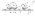
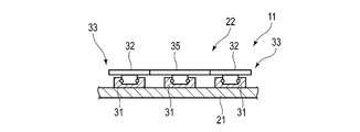
- FIG. 4 is a cross-sectional view showing a structure of a belt used in an electrocardiographic measuring device with a part omitted.
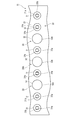
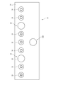
- FIG. 5 is a plan view showing the structure of the belt with a part omitted.
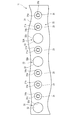
- FIG. 6 is a plan view showing the structure of the belt with a part omitted.
- FIG. 7 is an explanatory view showing the arrangement of the first electrode to the ninth electrode when the cross-sectional shape of the upper arm is assumed to be circular.
- FIG. 7 is an explanatory view showing the arrangement of the first electrode to the ninth electrode when the cross-sectional shape of the upper arm is assumed to be circular.
- FIG. 8 is a graph showing an example of time-series changes in the electrocardiogram waveform detected by each pair of electrodes.
- FIG. 9 is a graph showing an example of time-series changes in the electrocardiogram waveform detected by each pair of electrodes and ground electrodes in different subjects.
- FIG. 10 is an explanatory view showing an example of the distance between two electrodes on the upper arm.
- FIG. 11 is an explanatory diagram showing a histogram of the distances of the electrodes having the maximum potential difference.
- FIG. 12 is a cross-sectional view showing the structure of the belt according to the second embodiment with some omissions.
- FIG. 13 is a cross-sectional view showing the structure of the belt according to the third embodiment with some omissions.
- FIG. 14 is a cross-sectional view showing the structure of the belt according to the fourth embodiment with some omissions.
- FIG. 15 is a plan view showing the structure of the belt according to the fifth embodiment with some omissions.
- FIG. 16 is a plan view showing the structure of the belt according to the sixth embodiment with some omissions.
- FIG. 17 is a cross-sectional view showing the structure of the belt according to the seventh embodiment with some omissions.
- FIG. 18 is a plan view showing the structure of the belt according to another embodiment with some omissions.
- FIG. 19 is a plan view showing a belt configuration according to another embodiment with some omissions.
- FIG. 20 is a cross-sectional view showing a belt configuration according to another embodiment with some omissions.
- FIG. 21 is a cross-sectional view showing a belt configuration according to another embodiment with some omissions.
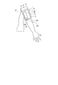
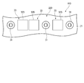
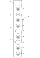
- FIG. 1 is an explanatory view showing the configuration of the electrocardiographic measuring device 1 according to the first embodiment of the present invention and showing a state in which the electrocardiographic measuring device 1 is attached to the upper arm 100 of a living body.
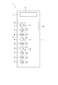
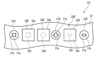
- FIG. 2 is a plan view showing the configuration of the electrocardiographic measuring device 1 from the living body side.
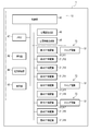
- FIG. 3 is a block diagram showing the configuration of the electrocardiographic measuring device 1.
- the electrocardiographic measuring device 1 is a potential measuring device that is attached to a living body, detects potentials at a plurality of locations on the surface of the skin of the living body, and generates electrocardiographic information necessary for generating an electrocardiogram based on the detected voltages. ..
- the electrocardiogram measuring device 1 may generate and display an electrocardiogram waveform, or may be configured to display information necessary for generating an electrocardiogram and output it to an external terminal.
- the electrocardiographic measuring device 1 includes a belt 11 and a device main body 12.
- the belt 11 and the device main body 12 are integrally formed.
- the electrocardiographic measuring device 1 functions as a so-called wearable device that is attached to the upper arm as a living body by, for example, a belt 11.
- FIG. 1 shows an example of a state in which the electrocardiographic measuring device 1 is attached to the upper arm 100 of the person to be measured.
- the electrocardiographic measuring device 1 may be configured such that the belt 11 and the device main body 12 are separately configured and connected via a signal line or the like.
- the belt 11 holds the device main body 12.
- the belt 11 is wrapped around the living body.
- the belt 11 is attached to, for example, the upper arm of the person to be measured.
- the belt 11 includes a belt main body 21, an electrode array 22, and fixing means 23.
- a part of the belt main body 21, a part of the structure of the electrode array 22, and the fixing means 23 are omitted, and in FIGS. 5 and 6, a part of the belt main body 21 and the fixing means 23 are omitted. And show.
- the belt body 21 is made of, for example, a flexible resin or fiber.
- the belt body 21 is set to a length that can be worn on the upper arm of the person to be measured who wears the electrocardiographic measuring device 1.
- the belt body 21 is formed in a long strip shape in one direction.
- the electrode array 22 is electrically connected to the device main body 12 via a signal line or the like.
- the electrode array 22 includes a plurality of base electrodes 31 and a plurality of cap electrodes 32.
- the plurality of base electrodes 31 are arranged side by side at equal intervals in the longitudinal direction of the belt body 21.
- the plurality of base electrodes 31 are electrically connected to the device main body 12, respectively.
- the base electrode 31 is formed so that the cap electrode 32 can be attached and detached.
- the number of base electrodes 31 can be appropriately set to a number capable of generating an electrocardiogram waveform even if the length of the upper arm of the subject to be measured is different.
- the base electrode 31 is set to the number of electrodes required to generate the electrocardiogram waveform, specifically, more than two, in order to correspond to the upper arms of various subjects.
- the cap electrode 32 is detachably formed on the base electrode 31.
- the number of cap electrodes 32 smaller than the number of base electrodes 31 is used to detect an electrocardiographic signal for generating an electrocardiogram waveform. That is, at least two cap electrodes 32 are provided so that the number of electrocardiographic signals required to generate the electrocardiogram waveform can be detected, specifically, two. For example, three cap electrodes 32 may be provided. In this case, the two cap electrodes 32 are used for the electrodes 33 that detect the potential on the surface of the skin of the upper arm. Further, one cap electrode 32 constitutes a ground electrode 33A. These three cap electrodes 32 have nine bases so that the electrocardiographic signal detected from the subject becomes a strong signal when the electrocardiographic measuring device 1 is attached to the upper arm of the subject. It is selectively mounted on the electrode 31.
- the base electrode 31 and the cap electrode 32 attached to the base electrode 31 constitute electrodes 33 and 33A for detecting an electrocardiographic signal.
- a base electrode 31 and a cap electrode 32 Specific examples of such a base electrode 31 and a cap electrode 32 are shown below.
- the base electrode 31 and the cap electrode 32 are formed so as to be fitted.
- FIGS. 2, 5 and 6 examples of different arrangements of the cap electrodes 32 mounted on the base electrodes 31 are shown.
- one of the base electrode 31 and the cap electrode 32 has a spring, and the other is formed in a snap button shape having a genko (convex shape).
- the base electrode 31 has a recess 31a and a spring 31b provided in the recess 31a.
- the base electrode 31 is fixed to the belt body 21 by sticking, sewing, fitting, caulking, or magnetic force.
- FIG. 4 shows an example in which the base electrode 31 is fixed to the belt body 21 by sticking or sewing.
- the cap electrode 32 is, for example, a dry electrode. As shown in FIGS. 4 to 6, the cap electrode 32 includes a flat plate-shaped electrode portion 32a that comes into contact with a living body and a genko 32b that is an insertion portion that is inserted into the recess 31a.
- the electrode portion 32a is formed, for example, with a circular flat surface having a surface in contact with a living body.
- the genko 32b is a protrusion, is inserted into the recess 31a of the base electrode 31, and is held by a spring 31b provided in the recess 31a to be selectively fixed to the base electrode 31.
- the fixing means 23 fixes the belt body 21 with the belt body 21 wrapped around the upper arm.
- the fixing means 23 is, for example, a hook-and-loop fastener.
- the hook-and-loop fastener includes a loop surface member and a hook surface member fixed to the front surface side and the back surface side of the belt body 21, respectively.
- the loop surface member and the hook surface member can be appropriately set for the area provided on the belt main body 21 and the like.
- the apparatus main body 12 includes a case 41, an operation unit 42, a display unit 43, a power supply unit 44, an electrocardiographic information generation unit 45, an electrocardiogram generation unit 46, a memory 47, and a control unit 48. ing. Further, the device main body 12 includes a communication unit that transmits / receives information to / from an external terminal. The communication unit transmits / receives information to / from an external terminal wirelessly and / or by wire.
- the case 41 accommodates a part of the operation unit 42, a part of the display unit 43, an electrocardiographic information generation unit 45, an electrocardiogram generation unit 46, a memory 47, and a control unit 48. Further, the case 41 exposes a part of the operation unit 42 and a part of the display unit 43 from the outer surface.
- the case 41 is fixed to the belt 11.
- the operation unit 42 inputs a command from the user.
- the operation unit 42 includes a plurality of buttons 42a and sensors that detect the operation of the buttons 42a.
- the operation unit 42 may include a pressure-sensitive touch panel, a capacitive touch panel, or the like, a microphone that receives a sound command, or the like provided on the case 41, the display unit 43, or the like.
- the operation unit 42 converts a command into an electric signal and outputs the electric signal to the control unit 48 when the user operates the operation unit 42.
- the display unit 43 is electrically connected to the control unit 48.
- the display unit 43 is, for example, a liquid crystal display (LCD: Liquid Crystal Display) or an organic electroluminescence display (OELD: Organic Electro Luminescence Display).
- the display unit 43 displays the date and time, electrocardiographic information, electrocardiogram waveform, and the like according to the control signal from the control unit 48.
- the display unit 43 displays various information including blood pressure values such as the displayed systolic blood pressure and diastolic blood pressure and measurement results such as heart rate. May be displayed.
- the power supply unit 44 is a power source.
- the power supply unit 44 is a secondary battery such as a lithium ion battery, for example.
- the power supply unit 44 is electrically connected to the control unit 48.
- the power supply unit 44 supplies power to the control unit 48.
- the power supply unit 44 supplies driving power to the operation unit 42, the display unit 43, the electrocardiographic information generation unit 45, the electrocardiogram generation unit 46, and the memory 47 via the control unit 48 and the control unit 48.
- the electrocardiographic information generation unit 45 is electrically connected to a plurality of base electrodes 31 of the electrode array 22 via, for example, a signal line.
- the electrocardiographic information generation unit 45 calculates the potential difference from the voltages detected by the two cap electrodes 32. Specifically, the electrocardiographic information generation unit 45 calculates the potential difference between the two cap electrodes 32 mounted at the two locations of the nine base electrodes 31, and generates electrocardiographic information.
- the electrocardiogram generation unit 46 is electrically connected to the electrocardiographic information generation unit 45.
- the electrocardiogram generation unit 46 generates electrocardiogram information based on the electrocardiographic information generated by the electrocardiographic information generation unit 45.
- the ECG information may include an ECG waveform.
- Such an electrocardiographic information generation unit 45 and an electrocardiogram generation unit 46 are processing circuits capable of executing the functions of the electrocardiographic information generation unit 45 and the electrocardiogram generation unit 46, respectively.
- the electrocardiographic information generation unit 45 and the electrocardiogram generation unit 46 are electrically connected to the control unit 48.
- the control unit 48 includes the processing circuits of the electrocardiographic information generation unit 45 and the electrocardiogram generation unit 46, and executes the program stored in the memory 47 to perform the functions of the electrocardiographic information generation unit 45 and the electrocardiogram generation unit 46. You may do it.
- the electrocardiographic information generation unit 45 or the electrocardiogram generation unit 46 may have a low-pass filter, an amplifier, and an analog / digital converter.
- a potential difference signal is converted into a digital signal by an analog / digital converter after removing unnecessary noise components with a low-pass filter and then amplifying the signal with an amplifier.
- the memory 47 includes, for example, SSD (Solid State Drive), RAM (Random Access Memory), ROM (Read Only Memory), and the like as storage media.
- the memory 47 stores a program necessary for executing various control processes. Further, the memory 47 stores the detected electrocardiographic signal, the generated electrocardiographic information, the electrocardiogram information, and the like. Further, for example, the memory 47 stores such information in chronological order.
- the control unit 48 includes a single processor or a plurality of processors.
- the control unit 48 is formed by one or more processing circuits.
- the control unit 48 is, for example, a CPU (Central Processing Unit).
- the control unit 48 executes the entire operation of the electrocardiographic measuring device 1 and a predetermined operation (function) based on the program stored in the memory 47.
- the control unit 48 executes a predetermined calculation, analysis, processing, or the like according to the read program.
- the control unit 48 controls the operation of the operation unit 42, the display unit 43, the electrocardiographic information generation unit 45, and the electrocardiogram generation unit 46, transmits / receives signals, and supplies electric power.
- cap electrodes 32 are attached to two selected locations suitable for electrocardiographic measurement of a plurality of base electrodes 31, and a pair of cap electrodes 32 having a suitable distance is formed. .. As a result, a pair of electrodes 33 for detecting the electrocardiographic signal is formed. Further, for example, the cap electrode 32 is attached to any one of the remaining base electrodes 31 to form the ground electrode 33A.
- the device main body 12 is arranged on the upper arm 100, and the belt main body 21 is fixed to the upper arm by the fixing means 23.
- the electrocardiographic measuring device 1 is attached to the upper arm of the person to be measured.
- the control unit 48 controls each configuration and detects the electrocardiographic signal via the base electrode 31 provided with the cap electrode 32.
- the electrocardiographic information generation unit 45 generates electrocardiographic information from the electrocardiographic signal
- the electrocardiogram generation unit 46 generates electrocardiographic information from the electrocardiographic information.
- the control unit 48 stores the electrocardiographic information and the electrocardiogram information in the memory 47, and displays information such as the date and time and the electrocardiogram on the display unit 43. Further, the control unit 48 may control the communication unit to transmit various information such as date and time, electrocardiographic information, and electrocardiogram information to an external terminal.
- An electrocardiographic measuring device 1 may be used as a device for deriving a pair of electrodes 33 having a suitable distance for each person to be measured, and electrodes having the same arrangement as the plurality of base electrodes 31 of the electrocardiographic measuring device 1 may be used. Other devices capable of electrocardiographic measurement may be used.
- the nine base electrodes 31 will be described as the first base electrode 311 to the ninth base electrode 319 in the order of arrangement.
- the electrocardiographic measuring device 1 when the electrocardiographic measuring device 1 is attached to the upper arm, the upper arm is in a posture in which the palm is facing upward, and as shown in FIG. 7, when the cross-sectional shape of the upper arm 100 is assumed to be circular, it is counterclockwise. It is assumed that the first electrode 311 to the ninth electrode 319 are located at intervals of 40 °.
- FIG. 7 is an explanatory view showing the arrangement of the first electrode 311 to the ninth electrode 319 when the cross-sectional shape of the upper arm 100 is assumed to be circular
- FIG. 8 is an electrocardiogram waveform detected by each pair of electrodes 33. It is a graph which shows an example of a time series change.
- the first electrode 311 to the ninth electrode 319 define pairs of electrodes having substantially the same interval, and the time series of the electrocardiogram waveform obtained from the potential difference detected in each electrode pair. This is a method of finding a change and finding the intensity of an electrocardiogram waveform in each electrode pair.
- the electrocardiographic measuring device 1 As a specific example, for example, as shown in FIG. 7, from the first electrode 311 to the ninth electrode 319 of the electrocardiographic measuring device 1 mounted on the upper arm 100, the first electrode 311 and the fifth electrode 315, the second electrode 312 Each pair of the 6th electrode 316, the 3rd electrode 313 and the 7th electrode 317, the 4th electrode 314 and the 8th electrode 318, and the 5th electrode 315 and the 9th electrode 319 is defined. Then, the electrocardiographic measuring device 1 is operated, electrocardiographic signals corresponding to the potentials of each of these electrode pairs are detected, and the electrocardiographic information generation unit 45 generates electrocardiographic information.
- the electrocardiogram waveform is generated from the electrocardiographic information by the electrocardiogram generation unit 46, as shown in FIG. 8, the electrocardiogram waveform by the pair of each electrode 33 is generated.
- An example of the time-series change of the electrocardiogram waveform V48 between the four electrodes 314 and the eighth electrode 318 and the electrocardiogram waveform V59 between the fifth electrode 315 and the ninth electrode 319 is shown.
- the electrocardiogram waveforms generated by each pair of electrodes 33 have different intensities.
- the maximum peak intensity of the electrocardiogram waveform V15 between the first electrode 311 and the fifth electrode 315 is the strongest, and the electrocardiogram waveform V26 between the second electrode 312 and the sixth electrode 316, the third electrode 313, and the seventh electrode 317.
- the intensities decrease in the order of the electrocardiogram waveform V37, and the electrocardiogram waveform V48 between the fourth electrode 314 and the eighth electrode 318 and the electrocardiogram waveform V59 between the fifth electrode 315 and the ninth electrode 319 become negative values.
- the electrocardiogram waveform V15 between the first electrode 311 and the fifth electrode 315 is selected for the electrocardiogram measurement, and the other pair of electrodes 33 becomes unnecessary. Therefore, thereafter, when the person to be measured detects the electrocardiogram information, the cap electrode 32 is attached to the first base electrode 311 and the fifth base electrode 315, and the electrode 33 for detecting the electrocardiographic signal is attached. A pair may be formed, and the cap electrode 32 for the ground electrode 33A may be attached to any of the other base electrodes 312, 313, 314, 316, 317, 318, and 319. As described above, according to the first example of the method of deriving the pair of electrodes 33, the position of the electrodes 33 having a high detection intensity of the electrocardiographic signal can be obtained according to the person to be measured.
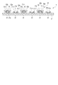
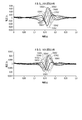
- FIG. 9 is a graph showing an example of time-series changes in the electrocardiogram waveform detected by each pair of electrodes 311 to 319 and a reference electrode in different subjects.
- the average value of the potential values of the first electrodes 311 to 9th electrodes 319 and the reference electrode such as the ground electrode is obtained as the reference potential, and the reference potential, the reference electrode, and each of the first electrodes 311 to 9th electrodes are obtained.
- the time-series changes of the electrocardiogram waveform obtained from the potential difference from the potential between 319 are obtained. Then, it is a method of defining the electrodes at which the voltage peaks on the plus side and the minus side as a pair.
- the electrocardiographic measuring device 1 mounted on the upper arm 100 shown in FIG. 7 is operated to detect an electrocardiographic signal corresponding to each potential from the first electrode 311 to the ninth electrode 319 and the reference electrode.
- the electrocardiographic information generation unit 45 generates electrocardiographic information.
- the electrocardiographic information generation unit 45 or the control unit 48 obtains an average value (AV) of an electrocardiographic signal corresponding to each potential.
- the electrocardiogram generation unit 46 generates an electrocardiogram waveform from the respective potentials of the ground electrode 33A and the first electrode 311 to the ninth electrode 319 and the average value (reference potential). As a result, as shown in FIG.
- an electrocardiogram waveform is generated by a pair of each electrode 311 to 319 and an average value of the electrocardiographic signal.
- the first electrode 311 and the average value electrocardiogram waveform V1AV, the second electrode 312 and the average value electrocardiogram waveform V2AV, the third electrode 313 and the average value electrocardiogram waveform are V3AV, the fourth electrode 314 and the average value electrocardiogram.
- Waveform V4AV, 5th electrode 315 and average ECG waveform V5AV, 6th electrode 316 and average ECG waveform V6AV, 7th electrode 317 and average ECG waveform V7AV, 8th electrode 318 and average ECG waveform V8AV , 9th electrode 319 and the time-series change of the electrocardiogram waveform V9AV of the average value are shown. Further, in FIG. 9, the electrocardiogram waveforms V1AV to V9AV of different subjects (Mr. A and Mr. B) are shown, respectively. The posture of the person to be measured when generating the electrocardiogram waveform was the supine position.
- the intensities of the electrocardiogram waveforms V1AV to V9AV differ on the positive side and the negative side of the voltage, respectively.
- the peak intensity of the fourth electrode 314 and the average value of the electrocardiogram waveform V4AV is maximized on the positive side of the voltage, and the first electrode 311 and the average value are on the negative side of the voltage.
- the peak intensity of the electrocardiogram waveform V1AV is maximized. Therefore, it can be estimated that the maximum peak intensity of the electrocardiogram waveform between the first electrode 311 and the fourth electrode 314 is the highest by pairing the first electrode 311 and the fourth electrode 314.
- the first electrode 311 and the fourth electrode 314 are selected for the electrocardiogram measurement, and the other electrodes 33 are unnecessary. Therefore, thereafter, when Mr. A, who is the subject to be measured, detects the electrocardiogram information, the cap electrode 32 is attached to the first base electrode 311 and the fourth base electrode 314 to detect the electrocardiographic signal. The electrode 33 of the above is formed. Then, the cap electrode 32 for the ground electrode 33A is attached to any of the other base electrodes 312, 313, 314, 316, 317, 318, and 319.
- the peak intensity of the electrocardiogram waveform and the peak intensity and The peak position is different.
- the peak intensity of the 6th electrode 316 and the average value of the electrocardiogram waveform V6AV is maximized on the positive side of the voltage, and the 2nd electrode 312 and the average value are on the negative side of the voltage.
- the peak intensity of the electrocardiogram waveform V2AV is maximized. Therefore, by pairing the second electrode 312 and the sixth electrode 316, it can be estimated that the maximum peak intensity of the electrocardiogram waveform between the second electrode 312 and the sixth electrode 316 is the highest.
- the second electrode 312 and the sixth electrode 316 are selected for the electrocardiogram measurement, and the other electrodes 33 are unnecessary. Therefore, thereafter, when Mr. B, who is the subject to be measured, detects the electrocardiogram information, the cap electrode 32 for detecting the electrocardiographic signal is attached to the second base electrode 312 and the sixth base electrode 316. , The cap electrode 32 for the ground electrode 33A may be attached to any of the other base electrodes 31. As described above, according to the second example, a suitable pair of electrodes 33 can be obtained according to the person to be measured.
- an example of the electrocardiogram waveforms of different subjects A and B as the subjects to be measured is shown, but the potential distribution of the electrocardiogram obtained for each subject is shown. different. Therefore, by deriving a pair of electrode positions suitable for the person to be measured and selecting the base electrode 31 on which the cap electrode 32 is mounted, two positions of the electrode 33 having a high maximum peak intensity can be obtained with a small number of cap electrodes 32. Can be done.
- FIG. 10 is an explanatory diagram showing an example of the distance between the two electrodes 33 on the upper arm 100.
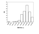
- FIG. 11 shows a histogram of the distance between the electrodes 33, which is the maximum potential difference.
- the cross section of the upper arm 100 is approximately circular, an electrode is placed at one point on the surface of the upper arm 100 from the center thereof, and a straight line having a predetermined angle ⁇ and the upper arm surface with respect to a straight line connecting the center to the upper arm surface. Place another electrode at the intersection with. Then, when the angle ⁇ is increased, the distance between the electrodes is increased.
- the angle should be 140 to 170 [deg] intervals. Therefore, for example, in the case of defining two electrode pairs in the first example, the angle may be defined within the range of 140 to 170 [deg] intervals. Further, in the second example, it is preferable to select a pair of electrodes having an angle of 140 to 170 [deg] intervals.
- the belt 11 and the electrocardiographic measuring device 1 configured in this way, a plurality of base electrodes 31 are provided in a number larger than the number required for generating electrocardiogram information, and the electrocardiographic signal is detected in these base electrodes 31.
- the cap electrode 32 for this purpose is selectively attached. Therefore, the electrocardiographic measuring device 1 can suitably detect an electrocardiographic signal with a small number of electrodes by attaching the cap electrode 32 to the base electrode 31 that can form a pair of electrodes 33 having a high maximum peak intensity.
- the pair of suitable electrodes 33 can generate electrocardiographic information. Further, by obtaining a suitable pair of electrodes 33 for each person to be measured in advance, the cap electrode 32 can be arranged at a position where the detection intensity of the electrocardiographic signal is high. The strength of the detected electrocardiographic signal can be improved.
- the cap electrodes 32 need only be provided at at least two of the plurality of base electrodes 31 and at three locations when the ground electrode 33A is formed. Therefore, since the electrocardiographic measuring device 1 can generate the electrocardiographic information and the electrocardiogram information by the pair of cap electrodes 32, the processing required for generating the electrocardiographic information and the electrocardiogram information can be reduced.
- each pair of electrodes has electrocardiographic information. And it is necessary to generate electrocardiogram information. Therefore, in the conventional electrocardiographic measuring device, it takes time and power consumption to process the generation of the electrocardiogram information, and the circuit for generating the electrocardiogram information becomes complicated.
- the electrocardiographic measuring device 1 it is sufficient to generate the electrocardiographic information and the electrocardiogram information with only one pair of electrodes 33. Therefore, the electrocardiographic measuring device 1 can suppress the processing time and power consumption, and can suppress the complexity of the circuit for generating the electrocardiogram waveform.
- the base electrode 31 and the cap electrode 32 constituting the electrode 33 removable, the position of the cap electrode 32 can be easily changed. Further, the base electrode 31 and the cap electrode 32 are configured in a snap button shape having a spring 31b on one side and a genko 32b on the other side. Therefore, the cap electrode 32 can be attached and detached more easily.
- the base electrode 31 is fixed to the belt body 21, only the cap electrode 32 can be selectively attached to the base electrode 31. Therefore, in order to change the electrode 33 in contact with the upper arm 100, the belt 11 only needs to move the cap electrode 32, and the position of the electrode 33 can be easily changed. Further, the base electrode 31 and the cap electrode 32 can easily fix the base electrode 31 and the cap electrode 32 by inserting one genko 32b into the other recess 31a and holding the genko 32b by the spring 31b. ..
- the electrocardiographic signal can be suitably detected with a small number of electrodes.
- FIG. 12 is a cross-sectional view schematically showing the configuration of the belt 11A.
- the belt 11A includes a belt main body 21 and an electrode array 22A.
- the electrode array 22A is electrically connected to the device main body 12 via a signal line or the like.
- the electrode array 22A includes a plurality of base electrodes 31A and a plurality of cap electrodes 32.
- the plurality of base electrodes 31A are arranged side by side at equal intervals in the longitudinal direction of the belt body 21.
- the plurality of base electrodes 31A are electrically connected to the device main body 12, respectively.
- the base electrode 31A is formed so that the cap electrode 32 can be attached and detached.
- the number of base electrodes 31A can be appropriately set to a number capable of generating an electrocardiogram waveform even if the length around the upper arm of the subject to be measured, which is expected to measure the electrocardiogram waveform, is different.
- the base electrodes 31A are set to a number larger than the number of electrodes required to generate the electrocardiogram waveform in order to correspond to the upper arms of various subjects. For example, nine base electrodes 31A are provided. In FIG. 12, the base electrode 31A is partially omitted.
- the base electrode 31A and the cap electrode 32 are shown below.
- the base electrode 31A and the cap electrode 32 are formed so as to be fitted.
- one of the base electrode 31A and the cap electrode 32 has a spring, and the other is formed in a snap button shape having a genko.
- the base electrode 31A has a recess 31a and a spring 31b provided in the recess 31a. Further, the base electrode 31A is fixed to the belt body 21 by fitting or caulking.
- the base electrode 31A has a main body 31c having a recess 31a and a spring 31b, and a hoso 31d for fixing the main body 31c to the belt main body 21. Then, the main body 31c and the hoso 31d are arranged on both main surfaces of the belt main body 21, respectively, and the base electrode 31A is fixed to the belt main body 21 by crimping the hoso 31d to the main body 31c.
- the belt 11A having such a configuration has the same effect as the belt 11 according to the first embodiment described above.
- the belt 11A has a structure in which the main body 31c and the hoso 31d are crimped with the belt main body 21 sandwiched between them, so that the base electrode 31A can be firmly fixed to the belt main body 21.
- FIG. 13 is a cross-sectional view schematically showing the configuration of the belt 11B.
- the belt 11B includes a belt main body 21 and an electrode array 22B.
- the electrode array 22B is electrically connected to the device main body 12 via a signal line or the like.
- the electrode array 22B includes a plurality of base electrodes 31B and a plurality of cap electrodes 32.
- the plurality of base electrodes 31B are arranged side by side at equal intervals in the longitudinal direction of the belt body 21.
- the plurality of base electrodes 31B are electrically connected to the device main body 12, respectively.
- the base electrode 31B is formed so that the cap electrode 32 can be attached and detached.
- the number of base electrodes 31B can be appropriately set to a number capable of generating an electrocardiogram waveform even if the length around the upper arm of the subject to be measured, which is expected to measure the electrocardiogram waveform, is different.
- the base electrodes 31B are set to a number larger than the number of electrodes required to generate the electrocardiogram waveform in order to correspond to the upper arms of various subjects. For example, nine base electrodes 31B are provided. In FIG. 13, the base electrode 31B is partially omitted.
- the base electrode 31B and the cap electrode 32 are shown below.
- the base electrode 31B and the cap electrode 32 are formed so as to be fitted.
- one of the base electrode 31B and the cap electrode 32 has a spring, and the other is formed in a snap button shape having a genko.
- the base electrode 31B has a recess 31a and a spring 31b provided in the recess 31a. Further, the base electrode 31B is fixed to the belt body 21 by a magnetic force.
- the base electrode 31B has a main body 31c having a recess 31a and a spring 31b, and a hoso 31d for fixing the main body 31c to the belt main body 21. Then, the main body 31c and the hoso 31d are formed by a magnet or have a magnet, have different magnetic poles in regions facing each other, and attract each other.
- the main body 31c and the hoso 31d are arranged on both main surfaces of the belt main body 21, respectively, and the base electrode 31B is fixed to the belt main body 21 by the magnetic force of the main body 31c and the hoso 31d.
- One of the main body 31c and the hoso 31d may be formed of a magnet, or may include a magnet and the other may be made of a magnetic metal material.
- the belt 11B having such a configuration has the same effect as the belt 11 according to the first embodiment described above.
- it can be fixed to the base electrode 31B by magnetic force on the belt body 21.
- FIG. 14 is a cross-sectional view schematically showing the configuration of the belt 11C.
- the belt 11C includes a belt body 21 and an electrode array 22C.
- the electrode array 22C is electrically connected to the device main body 12 via a signal line or the like.
- the electrode array 22C includes a plurality of base electrodes 31C and a plurality of cap electrodes 32C.
- the plurality of base electrodes 31C are arranged side by side at equal intervals in the longitudinal direction of the belt body 21.
- the plurality of base electrodes 31C are electrically connected to the device main body 12, respectively.
- the base electrode 31C is formed so that the cap electrode 32C can be attached and detached.
- the number of base electrodes 31C can be appropriately set to a number capable of generating an electrocardiogram waveform even if the length around the upper arm of the subject to be measured, which is expected to measure the electrocardiogram waveform, is different.
- the base electrodes 31C are set to a number larger than the number of electrodes required to generate the electrocardiogram waveform in order to correspond to the upper arms of various subjects. For example, nine base electrodes 31C are provided. In FIG. 14, the base electrode 31C is partially omitted.
- the base electrode 31C and the cap electrode 32C are formed so as to be fixed by a magnetic force.
- the base electrode 31C and the cap electrode 32C has a recess, and the other has a genko.
- the base electrode 31C and the cap electrode 32C have different magnetic poles in regions facing each other, and by inserting a genko into the recess, they are attracted to each other and fixed to each other.
- the base electrode 31C has a recess 31a. Further, the base electrode 31C is fixed by, for example, sticking, sewing, fitting, caulking, or magnetic force. For example, the base electrode 31C is fixed to the belt body 21 by sticking or sewing, as shown in FIG. 14 from the second from the left to the first from the right. As shown first from the left in FIG. 14, the base electrode 31C has a main body 31c and a hoso 31d, and the main body 31c and the hoso 31d are also formed of a magnet or have a magnet and face each other. It may be configured to have different magnetic poles in the regions to be formed and to attract each other. That is, the electrode 33 may have a configuration in which the main body 31c and the hoso 31d are fixed by a magnetic force, and the main body 31c and the cap electrode 32C are fixed by a magnetic force.
- the belt 11C having such a configuration has the same effect as the belt 11 according to the first embodiment described above.
- the base electrode 31C and the cap electrode 32C are configured to be attracted to each other by a magnetic force, the cap electrode 32C need only be attached to the base electrode 31C by bringing the cap electrode 32C closer to the base electrode 31C. Therefore, the wearability of the cap electrode 32C can be improved.
- the present invention is not limited to the above-described embodiment.
- the cap electrode 32 has been described in which the surface of the electrode portion 32a in contact with the living body is formed in a circular planar shape, but the present invention is not limited thereto.
- a polygonal shape specifically a rectangular shape, more specifically, a square shape or a rectangular shape. It may be configured in a plane shape of.
- the cap electrode 32D By forming the cap electrode 32D into a polygonal shape, more preferably a rectangular shape, the area of the electrode portion 32a of the cap electrode 32D in contact with the living body can be increased as compared with the circular shape.
- the electrode 33 (cap electrode 32D) is used for acquiring an electrocardiographic signal, it is desirable that the electrode 33 has a large size in contact with a living body in order to secure a necessary signal / noise ratio.
- the surface shape of the electrode portion 32a of the suitable cap electrode 32D capable of increasing the size of the electrode 33 is typically a square or rectangular rectangular shape. Therefore, by making the surface shape of the electrode portion 32a of the cap electrode 32D rectangular, the size of the electrode 33 in contact with the living body can be increased, and the required signal / noise ratio can be easily secured.
- the cap electrode 32D rotates around the axis of the genko 32b. Therefore, when the cap electrodes 32D are adjacent to each other, the adjacent cap electrodes 32D may interfere with each other.
- the recess 31a provided on one of the base electrode 31E and the cap electrode 32E, and the base electrode The genko 32b provided on the other side of the 31E and the cap electrode 32E may have an opening cross-sectional shape other than a circular shape or a cross-sectional shape.
- the shapes of the depression 31a and the genko 32b in a plan view may be a shape other than a circle such as a rectangle including a square, a rectangle, a trapezoid, an ellipse, a star, and a cross.
- the belt 11E having such a configuration when the cap electrode 32E is attached to the base electrode 31E in a predetermined posture, the recess 31a and the genko 32b interfere with each other around the axis, so that the base electrode 31E is the shaft of the genko 32b. It can suppress the rotation around the heart. Therefore, it is possible to prevent the adjacent cap electrodes 32E from coming into contact with each other.
- the posture of the genko 32b when the genko 32b is inserted into the recess 31a is limited, the posture of the cap electrode 32E is also limited. Therefore, the cap electrode 32E can be attached to the base electrode 31E in a suitable posture only by inserting the genko 32b into the recess 31a.
- the cap electrode 32 is used as a dry electrode, but the present invention is not limited to this.
- the cap electrode may be a wet electrode.
- a conductive wet member 32c is provided on the surface of the electrode portion 32a on the living body side, such as the cap electrode 32F of the electrode array 22F of the belt 11F according to the seventh embodiment shown in FIG. The configuration may be provided.
- the wet member 32c can reduce the surface resistance between the surface of the electrode portion 32a of the electrodes 33 and 33A (cap electrode 32F) and the surface of the living body such as a conductive gel sheet, and can reduce the signal / noise ratio of the electrocardiographic signal. If it is made of a material that can be enlarged, it can be set as appropriate.
- the ground electrode 33A may not be configured by attaching the cap electrode 32 to the base electrode 31, but may be configured to be provided on the belt 11 in advance.
- the ground electrode 33A may be arranged at a position deviated from the base electrode 31 in a direction orthogonal to the arrangement direction of the base electrodes 31, and FIG. 19 shows.
- the configuration may be such that the plurality of arranged base electrodes 31 are arranged side by side with the base electrodes 31 arranged at one end in the arrangement direction.
- a ground electrode 33A may have a circular electrode portion, a rectangular shape, or a polygonal shape other than the rectangular shape.
- the belt 11 may have a configuration that does not have a ground electrode.
- the configuration in which the base electrode 31 without the cap electrode 32 is attached is described as being exposed to the outside as it is, but the present invention is not limited to this.
- the base electrode 31 without the cap electrode 32 is not attached.
- the electrode 31 may be provided with a cap 35 made of a non-conductive material.
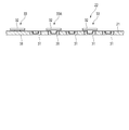
- the configuration in which the base electrode 31 is provided on the main surface of the belt body 21 on the living body side has been described, but the present invention is not limited to this, and as shown in FIG. May be good.
- the present invention is not limited to this, and the base electrode 31 has the genko 32b and the cap electrode 32 has the genko 32b. It may be configured to have a recess 31a.
- the base electrode 31 and the cap electrode 32 have been described with various configurations having the recess 31a and the genko 32b, but the above-mentioned configuration is not limited to the above-mentioned example.
- the recess 31a and the genko 32b may have a female screw and a male screw, and the recess 31a and the genko 32b may be fixed by screwing the recess 31a and the genko 32b.
- the base electrode 31 and the cap electrode 32 may have a configuration that does not have a recess 31a, a spring 31b, and a genko 32b.
- the electrocardiographic measuring device 1 has been described by using an example in which the belt 11 is attached to the upper arm, but the electrocardiographic measuring device 1 may be attached to the chest or other parts of the living body.
- the belt 11 may have a configuration used in a biometric information measuring device provided for electrocardiographic measurement and blood pressure measurement.
- the biological information measuring device produces a blood pressure measuring function of generating a blood pressure value from the pulse wave sensor and the pulse wave information detected by the pulse wave sensor. It may be configured to have a processing circuit or the like.
- Such a biological information measuring device exerts a function of calculating a pulse wave velocity (PTT) for each heartbeat and estimating a blood pressure value.
- PTT pulse wave velocity
- such a biological information measuring device is, for example, a pulse for each heartbeat, which is one of the feature quantities from the R wave peak RP detected by the electrocardiographic signal and the pulse wave signal detected by the pulse wave sensor.
- the pulse wave propagation time (PTT) for each heartbeat is calculated based on the time difference from the wave rising PS.
- the present invention can constitute various inventions by an appropriate combination of a plurality of constituent elements disclosed in each of the above embodiments. For example, some components may be removed from all the components shown in each embodiment. In addition, components from different embodiments may be combined as appropriate.
- Electrocardiographic measuring device 11 ... Belt 11A ... Belt 11B ... Belt 11C ... Belt 11D ... Belt 11E ... Belt 11F ... Belt 12 ... Device body 21 ... Belt body 22 ... Electrode array 22A ... Electrode array 22B ... Electrode array 22C ... Electrode Array 22D ... Electrode array 22E ... Electrode array 22F ... Electrode array 23 ... Fixing means 31 ... Base electrode 31A ... Base electrode 31b ... Spring 31B ... Base electrode 31c ... Main body 31C ... Base electrode 31d ... 32a ... Electrode portion 32b ... Genko 32c ... Wet member 32C ... Cap electrode 32D ... Cap electrode 32E ... Cap electrode 32F ... Cap electrode 33 ...
- Electrode 33A Ground electrode 35 ... Cap 41 ... Case 42 ... Operation unit 42a ... Button 43 ... Display Unit 44 ... Power supply unit 45 ... Electrocardiographic information generation unit 46 ... Electrocardiogram generation unit 47 ... Memory 48 ... Control unit 100 ... Upper arm
Landscapes
- Health & Medical Sciences (AREA)
- Life Sciences & Earth Sciences (AREA)
- Medical Informatics (AREA)
- Biophysics (AREA)
- Pathology (AREA)
- Engineering & Computer Science (AREA)
- Biomedical Technology (AREA)
- Heart & Thoracic Surgery (AREA)
- Physics & Mathematics (AREA)
- Molecular Biology (AREA)
- Surgery (AREA)
- Animal Behavior & Ethology (AREA)
- General Health & Medical Sciences (AREA)
- Public Health (AREA)
- Veterinary Medicine (AREA)
- Cardiology (AREA)
- Vascular Medicine (AREA)
- Physiology (AREA)
- Measurement And Recording Of Electrical Phenomena And Electrical Characteristics Of The Living Body (AREA)
Priority Applications (3)
| Application Number | Priority Date | Filing Date | Title |
|---|---|---|---|
| CN202180017522.0A CN115243613A (zh) | 2020-03-31 | 2021-03-01 | 带及心电测定装置 |
| DE112021000590.1T DE112021000590T5 (de) | 2020-03-31 | 2021-03-01 | Manschette und elektrokardiographische messvorrichtung |
| US17/934,929 US20230021062A1 (en) | 2020-03-31 | 2022-09-23 | Belt and electrocardiographic measurement device |
Applications Claiming Priority (2)
| Application Number | Priority Date | Filing Date | Title |
|---|---|---|---|
| JP2020-062900 | 2020-03-31 | ||
| JP2020062900A JP7404976B2 (ja) | 2020-03-31 | 2020-03-31 | ベルト及び心電測定装置 |
Related Child Applications (1)
| Application Number | Title | Priority Date | Filing Date |
|---|---|---|---|
| US17/934,929 Continuation US20230021062A1 (en) | 2020-03-31 | 2022-09-23 | Belt and electrocardiographic measurement device |
Publications (1)
| Publication Number | Publication Date |
|---|---|
| WO2021199827A1 true WO2021199827A1 (ja) | 2021-10-07 |
Family
ID=77928380
Family Applications (1)
| Application Number | Title | Priority Date | Filing Date |
|---|---|---|---|
| PCT/JP2021/007619 Ceased WO2021199827A1 (ja) | 2020-03-31 | 2021-03-01 | ベルト及び心電測定装置 |
Country Status (5)
| Country | Link |
|---|---|
| US (1) | US20230021062A1 (enExample) |
| JP (1) | JP7404976B2 (enExample) |
| CN (1) | CN115243613A (enExample) |
| DE (1) | DE112021000590T5 (enExample) |
| WO (1) | WO2021199827A1 (enExample) |
Cited By (2)
| Publication number | Priority date | Publication date | Assignee | Title |
|---|---|---|---|---|
| US12178580B2 (en) | 2019-12-23 | 2024-12-31 | Alimetry Limited | Electrode patch and connection system |
| EP4440434A4 (en) * | 2021-11-29 | 2025-09-03 | Demedar Spolka Z Ograniczona Odpowiedzialnoscia | ARM-WORN ELECTROCARDIOGRAPHIC DEVICE AND METHOD FOR MEASURING ELECTROCARDIOGRAPHIC SIGNAL |
Families Citing this family (1)
| Publication number | Priority date | Publication date | Assignee | Title |
|---|---|---|---|---|
| JP2025131201A (ja) * | 2024-02-28 | 2025-09-09 | オムロンヘルスケア株式会社 | 生体情報測定装置 |
Citations (2)
| Publication number | Priority date | Publication date | Assignee | Title |
|---|---|---|---|---|
| JPS57187505U (enExample) * | 1981-05-27 | 1982-11-29 | ||
| JP2020005863A (ja) * | 2018-07-06 | 2020-01-16 | オムロンヘルスケア株式会社 | ベルト及び心電測定装置 |
Family Cites Families (6)
| Publication number | Priority date | Publication date | Assignee | Title |
|---|---|---|---|---|
| JP5428889B2 (ja) | 2010-01-21 | 2014-02-26 | セイコーエプソン株式会社 | 心電計測装置 |
| CN103505201B (zh) * | 2013-10-24 | 2015-10-07 | 刘卫明 | 可配置干湿方式的穿戴式心电电极 |
| CN107708542B (zh) * | 2015-07-08 | 2021-01-15 | 日本电信电话株式会社 | 活体电极及可穿戴式电极 |
| KR101745423B1 (ko) * | 2015-11-17 | 2017-06-12 | 서울대학교산학협력단 | 다채널 뇌파 측정 장치 |
| CN107928662A (zh) * | 2017-12-07 | 2018-04-20 | 深圳市优科无线有限公司 | 一种支持在腕部和胸口同时测量的心电可穿戴装置 |
| CN209529122U (zh) * | 2018-11-26 | 2019-10-25 | 北京汇芯通电子科技有限公司 | 一种穿戴式远程心电数据监测仪 |
-
2020
- 2020-03-31 JP JP2020062900A patent/JP7404976B2/ja active Active
-
2021
- 2021-03-01 CN CN202180017522.0A patent/CN115243613A/zh active Pending
- 2021-03-01 DE DE112021000590.1T patent/DE112021000590T5/de active Pending
- 2021-03-01 WO PCT/JP2021/007619 patent/WO2021199827A1/ja not_active Ceased
-
2022
- 2022-09-23 US US17/934,929 patent/US20230021062A1/en active Pending
Patent Citations (2)
| Publication number | Priority date | Publication date | Assignee | Title |
|---|---|---|---|---|
| JPS57187505U (enExample) * | 1981-05-27 | 1982-11-29 | ||
| JP2020005863A (ja) * | 2018-07-06 | 2020-01-16 | オムロンヘルスケア株式会社 | ベルト及び心電測定装置 |
Cited By (3)
| Publication number | Priority date | Publication date | Assignee | Title |
|---|---|---|---|---|
| US12178580B2 (en) | 2019-12-23 | 2024-12-31 | Alimetry Limited | Electrode patch and connection system |
| US12245862B2 (en) | 2019-12-23 | 2025-03-11 | Alimetry Limited | Electrode patch and connection system |
| EP4440434A4 (en) * | 2021-11-29 | 2025-09-03 | Demedar Spolka Z Ograniczona Odpowiedzialnoscia | ARM-WORN ELECTROCARDIOGRAPHIC DEVICE AND METHOD FOR MEASURING ELECTROCARDIOGRAPHIC SIGNAL |
Also Published As
| Publication number | Publication date |
|---|---|
| CN115243613A (zh) | 2022-10-25 |
| JP2021159253A (ja) | 2021-10-11 |
| JP7404976B2 (ja) | 2023-12-26 |
| US20230021062A1 (en) | 2023-01-19 |
| DE112021000590T5 (de) | 2022-12-01 |
Similar Documents
| Publication | Publication Date | Title |
|---|---|---|
| US20230021062A1 (en) | Belt and electrocardiographic measurement device | |
| KR20190065102A (ko) | 심전도 측정 장치 | |
| US20140073979A1 (en) | eCard ECG Monitor | |
| EP3900622B1 (en) | Wireless electrocardiogram monitoring device | |
| US12295734B2 (en) | Wireless electrocardiogram monitoring device | |
| EP2049013A2 (en) | Device for mobile electrocardiogram recording | |
| KR101012810B1 (ko) | 단채널 휴대용 무선 심전도 측정장치 및 방법 | |
| US20170156615A1 (en) | Disposable heart monitoring system, apparatus and method | |
| US8060191B2 (en) | Wireless cardiogram signal diagnostic instrument | |
| US20230012616A1 (en) | Belt and electrocardiographic measurement device | |
| JP2007195690A (ja) | 携帯型心電計測装置 | |
| KR20220003170A (ko) | 보조 심전도(ecg) 조립체 및 보조 ecg 조립체를 포함하는 임상 데이터 획득 시스템(auxiliary electrocardiogram (ecg) assemblies and clinical data acquisition systems including auxiliary ecg assemblies) | |
| CN107530008B (zh) | 传感器单元 | |
| JP2006506160A (ja) | 簡単化された電極を有する個人との生体電気的相互作用のためのシステム | |
| EP3723597B1 (en) | An ecg device | |
| JP6215987B2 (ja) | 生体信号モニタシステム | |
| JP5913485B2 (ja) | 生体信号モニタシステム | |
| KR20100059159A (ko) | 생체 신호 측정모듈용 센서 및 이의 제조방법, 그리고 생체신호 측정모듈용 센서를 부착한 의류 | |
| KR20050001145A (ko) | 경락진단장치 | |
| KR102669215B1 (ko) | 심전도 측정 장치 및 방법 | |
| KR20200000406A (ko) | 심전도 측정 장치 | |
| TWM582824U (zh) | 多重生理檢測裝置 | |
| CN210931404U (zh) | 心电记录仪 | |
| KR20200024044A (ko) | 인체 신호 검출 헤드셋 장치 | |
| JP2025118443A (ja) | 生体情報測定装置 |
Legal Events
| Date | Code | Title | Description |
|---|---|---|---|
| 121 | Ep: the epo has been informed by wipo that ep was designated in this application |
Ref document number: 21779239 Country of ref document: EP Kind code of ref document: A1 |
|
| 122 | Ep: pct application non-entry in european phase |
Ref document number: 21779239 Country of ref document: EP Kind code of ref document: A1 |