WO2021199180A1 - 内視鏡の湾曲部、内視鏡挿入部、内視鏡 - Google Patents
内視鏡の湾曲部、内視鏡挿入部、内視鏡 Download PDFInfo
- Publication number
- WO2021199180A1 WO2021199180A1 PCT/JP2020/014614 JP2020014614W WO2021199180A1 WO 2021199180 A1 WO2021199180 A1 WO 2021199180A1 JP 2020014614 W JP2020014614 W JP 2020014614W WO 2021199180 A1 WO2021199180 A1 WO 2021199180A1
- Authority
- WO
- WIPO (PCT)
- Prior art keywords
- curved
- tip
- endoscope
- curved piece
- groove
- Prior art date
- Legal status (The legal status is an assumption and is not a legal conclusion. Google has not performed a legal analysis and makes no representation as to the accuracy of the status listed.)
- Ceased
Links
Images




















Classifications
-
- A—HUMAN NECESSITIES
- A61—MEDICAL OR VETERINARY SCIENCE; HYGIENE
- A61B—DIAGNOSIS; SURGERY; IDENTIFICATION
- A61B1/00—Instruments for performing medical examinations of the interior of cavities or tubes of the body by visual or photographical inspection, e.g. endoscopes; Illuminating arrangements therefor
- A61B1/005—Flexible endoscopes
- A61B1/0051—Flexible endoscopes with controlled bending of insertion part
- A61B1/0055—Constructional details of insertion parts, e.g. vertebral elements
-
- A—HUMAN NECESSITIES
- A61—MEDICAL OR VETERINARY SCIENCE; HYGIENE
- A61B—DIAGNOSIS; SURGERY; IDENTIFICATION
- A61B1/00—Instruments for performing medical examinations of the interior of cavities or tubes of the body by visual or photographical inspection, e.g. endoscopes; Illuminating arrangements therefor
- A61B1/005—Flexible endoscopes
- A61B1/0051—Flexible endoscopes with controlled bending of insertion part
- A61B1/0057—Constructional details of force transmission elements, e.g. control wires
-
- A—HUMAN NECESSITIES
- A61—MEDICAL OR VETERINARY SCIENCE; HYGIENE
- A61B—DIAGNOSIS; SURGERY; IDENTIFICATION
- A61B1/00—Instruments for performing medical examinations of the interior of cavities or tubes of the body by visual or photographical inspection, e.g. endoscopes; Illuminating arrangements therefor
- A61B1/005—Flexible endoscopes
- A61B1/008—Articulations
Definitions
- the present invention relates to a curved portion of an endoscope provided in an endoscope insertion portion, an endoscope insertion portion, and an endoscope, which are curved by being pulled by a wire.
- endoscopes have been widely used in the medical and industrial fields.
- the endoscope can observe and treat the test site in the subject by inserting the elongated insertion portion into the subject.
- a curved portion that can be curved in a plurality of directions is provided on the tip side of the insertion portion of the endoscope.
- the curved portion improves the progress of the insertion portion at the bent portion in the pipeline, and also changes the observation direction of the observation optical system provided at the tip portion located in front of the curved portion at the insertion portion.
- the curved portion is composed of, for example, a plurality of curved pieces having a predetermined length along the longitudinal axis of the insertion portion and having a cylindrical meat portion.
- the curved portion a plurality of rotatable rivets and curved portions in which adjacent curved pieces are curved in the vertical direction in a direction along the longitudinal axis of the plurality of curved pieces (hereinafter referred to as the longitudinal axis direction).
- the sword can be bent in four directions, up, down, left and right, by being connected via a plurality of rotatable rivets that bend in the left-right direction.
- tow wires which are movable back and forth in the longitudinal axis direction and whose tip is fixed to the curved piece located at the most tip side among the plurality of curved pieces (hereinafter, , Simply referred to as a wire) is inserted.
- the curved part By pulling one of the four wires from the operation part of the endoscope, the curved part can be bent in either the up, down, left, or right direction.
- curved pieces adjacent to each other in the longitudinal axis direction are connected by a pair of rivets, and a pair of wires inserted in the insertion portion, that is, two wires, either vertically or horizontally.
- a pair of wires inserted in the insertion portion that is, two wires, either vertically or horizontally.
- a configuration that can be bent in two directions in that direction is also well known.
- an endoscope used in the medical field for example, in a configuration such as a renal pelvis ureteroscope that requires a small-diameter insertion portion having a diameter of 5 mm or 3 mm or less, in a configuration using a rivet as described above, , There is a problem that it becomes difficult to reduce the diameter of the curved portion by the amount that each rivet is used.
- Japanese Patent Application Laid-Open No. 2005-7068 states that in order to reduce the diameter of the curved portion, the abutting portions provided at the ends oriented in the longitudinal axis direction abut each other and each other.
- a plurality of rotatable curved pieces are continuously provided along the longitudinal axis direction, and four wires penetrate the annular meat portion of each curved piece, so that the annular meat portion functions as a wire receiver.
- the configuration of the curved portion having a less structure is disclosed.
- the meat portion has a predetermined wall thickness and also has a configuration in which the meat portion protrudes inward in the radial direction of the longitudinal axis from the inner circumference of the curved piece. ..
- each curved piece is formed thinly, but when each curved piece is formed from resin, there is also a problem that the meat portion cannot be formed thinly due to a molding problem. ..
- each curved piece or a plurality of wire receivers of the tubular member Since the wires are passed through the through holes one by one from the front or the rear over the entire length of the curved portion in the longitudinal axis direction, it takes time to assemble the wires, that is, the wire can be assembled to the curved portion. There was also a problem that the manufacturing cost was high due to the bad condition.
- the present invention has been made in view of the above problems, and is an endoscope having a configuration in which the accommodation space for internal objects can be secured as large as possible and the wire assembling property is improved while reducing the diameter. It is an object of the present invention to provide a curved portion, an endoscope insertion portion, and an endoscope.
- the curved portion of the endoscope is a curved portion of the endoscope provided in the endoscope insertion portion, which is curved by pulling a wire.
- the first curved piece has a width substantially the same as the outer diameter of the wire, which communicates with the hole and is formed from the inner circumference of the first curved piece toward the outer side in the radial direction of the longitudinal axis.
- the wire has a second groove formed in, and the wire is arranged in the first groove and the second groove.
- the endoscope insertion portion is formed in a tubular shape and includes a curved portion of the endoscope.
- the endoscope according to one aspect of the present invention includes the endoscope insertion portion.
- FIG. 6 is a cross-sectional view showing a modified example in which each tip portion and each base end portion in the first groove of the first curved piece and the second groove of the second curved piece are notched.
- FIG. 7 is a cross-sectional view showing a modified example in which each tip portion and each base end portion in the first groove of the first curved piece and the second groove of the second curved piece are notched.
- FIG. 8 is a cross-sectional view showing a modified example in which each tip portion and each base end portion in the first groove of the first curved piece and the second groove of the second curved piece are notched.
- Partial cross-sectional view showing a plurality of curved pieces constituting the curved portion of the third embodiment together with two wires. The cross section of the first curved piece along the XIII-XIII line in FIG. 12 is shown side by side with the wire along with the cross section of the second curved piece along the XIII'-XIII' line in FIG.
- Partial cross-sectional view of the curved part of a general endoscope Partial cross-sectional view showing a plurality of curved pieces constituting the curved portion of this configuration
- Perspective view of the other curved piece of FIG. Partial cross-sectional view at the connecting portion between the active bending part and the passive bending part in the bending part of this configuration
- Enlarged perspective view of the main part showing the schematic configuration of the tip of the endoscope according to the fourth embodiment in an enlarged manner.
- Side view of the tip of the endoscope in FIG. An exploded perspective view showing a state in which the tip cover is removed at the tip of the endoscope in FIG.
- FIG. 22 An exploded perspective view showing a state in which the tip cover is removed at the tip of the endoscope in FIG. 22.
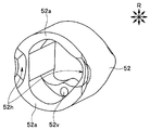
- FIG. 25 when viewed from the direction of arrow [28].
- Schematic perspective view showing a part of the internal structure of the endoscope operation unit In the seventh embodiment, a cross-sectional view showing a configuration example in which the sleeve at the tip of the wire is connected to the curved tip piece.
- Cross-sectional view showing a configuration example in which the sleeve provided at the tip of the wire is heat-welded to the outer skin of the curved portion through the notch hole in the first modification of the seventh embodiment.
- FIG. 9 is a cross-sectional view showing a configuration example of a passive curved portion provided between the curved portion and the flexible pipe portion in the ninth embodiment.
- FIG. 9 is a cross-sectional view showing an example in which the three-layer flexible tube is covered with the outer skin of the passive bending portion to form the passive bending portion in the ninth embodiment.
- Sectional view showing In the ninth embodiment, the tip of the three-layer flexible tube and the outer peripheral surface of the rear end curved piece, and the rear end of the three-layer flexible tube and the outer peripheral surface of the front mouthpiece of the flexible tube portion are connected by laser welding.
- the tip end of the three-layer flexible tube is connected to the inner peripheral surface of the rear end curved piece
- the rear end portion of the three-layer flexible tube is connected to the inner peripheral surface of the front mouthpiece of the flexible tube portion.
- Cross-sectional view showing a configuration example In the first modification of the ninth embodiment, a cross-sectional view showing a configuration example in which a rear end curved piece is insert-molded into a metal pipe and a three-layer flexible tube of a passive curved portion is laser-welded to the metal pipe.
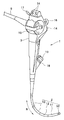
- FIG. 1 is a partial perspective view showing an endoscope having a curved portion of the endoscope of the present embodiment in the endoscope insertion portion. Twice
- the endoscope 1 is an elongated and flexible tubular endoscope insertion portion (hereinafter, referred to as a longitudinal axis direction) along a direction N along a longitudinal axis (hereinafter referred to as a longitudinal axis direction). (Simply referred to as an insertion portion) 2, an operation portion 3 provided on the base end side of the insertion portion 2, a universal cord 5 extending from the operation portion 3, and an extension end of the universal cord 5.
- the main part is composed of an image processing device (not shown) and a connector (not shown) connected to a light source device or the like.
- the insertion portion 2 is, in order from the tip side, a rigid tip portion 10 having an observation optical system or the like (not shown) inside, and a plurality of directions, for example, upper (U), which are connected to the base end side of the tip portion 10.
- a bending portion 11 which is an active bending portion that can be actively bent in the lower two directions, and a passive bending portion 12 that is connected to the base end side of the bending portion 11 and is passively bendable in a plurality of directions.
- a flexible flexible tube portion 13 which is connected to the base end side of the passive bending portion 12 and has flexibility, constitutes a main portion.
- the curved portion 11 is moved in either the upper or lower direction by pulling one of the wires 30u and 30d (both of which are referred to in FIG. 2) described later with the operation of the bending operation lever 15 described later. Be curved.
- the curved portion 11 may have a configuration that can be bent in two directions, left and right, and may be configured so that it can be bent in four directions of up, down, left, and right, and further, a configuration that can be bent in a composite direction of up, down, left, and right.
- the configuration in which the passive bending portion 12 is provided in the endoscope 1 is shown as an example, but the flexible tube portion 13 is directly provided on the base end side of the bending portion 11. It may be a continuous configuration.
- a remote switch 14 for giving image control instructions such as freeze and release, a bending operation lever 15 for bending operation of the bending part 11, and suction for performing suction operation.
- a button 16 and a suction base 17 communicating with a suction channel (not shown) provided in the insertion portion 2 are provided. Twice
- a treatment tool insertion port 18 for inserting a treatment tool such as a forceps into the suction channel is provided on the tip end side of the operation unit 3, and the forceps plug 19 can be detached from the treatment tool insertion port 18. ing.
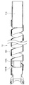
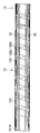
- FIG. 2 is a partial cross-sectional view showing a plurality of bending pieces constituting the bending portion of FIG. 1 together with two wires
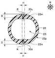
- FIG. 3 is a first bending piece of the bending portion along the line III-III in FIG.
- FIG. 4 is a diagram showing a cross section together with a wire
- FIG. 4 is a diagram showing a cross section of a second curved piece of a curved portion along the IV-IV line in FIG. 2 together with a wire.
- a plurality of first bending pieces 21 and a plurality of second bending pieces 22 are connected along the longitudinal axis direction N. It is composed of.
- first curved piece 21 and the second curved piece 22 are connected and arranged so as to be adjacent to each other along the longitudinal axis direction N.
- the first curved piece 21, the second curved piece 22, the first curved piece 21, the second curved piece 22, and so on, the longitudinal axis direction N They are arranged alternately connected along the line.
- first curved pieces 21 and three second curved pieces 22 are alternately connected along the longitudinal axis direction N, as an example.
- the number of the first curved piece 21 and the second curved piece 22 is not limited thereto.
- first curved piece 21 and the second curved piece 22 may be one or a plurality of each. Further, the number of the first curved piece 21 and the number of the second curved piece 22 may be the same, or the number may be different.
- first curved piece 21 and the second curved piece 22 are covered with a known blade and a known curved rubber, but in FIG. 2, they are omitted for simplification of the drawings. ing.
- the first curved piece 21 has a predetermined length along the longitudinal axis direction N, penetrates in the longitudinal axis direction, and various known internal objects such as a light guide and an imaging cable are arranged in the curved portion 11. It is formed in a tubular shape by forming the holes 21i to be formed.
- the first curved piece 21 is made of, for example, resin.
- the second curved piece 22 also has a predetermined length along the longitudinal axis direction N, and is formed with a hole 22i that penetrates inside in the longitudinal axis direction and in which the above-mentioned various known internal objects are arranged. By doing so, it is formed into a tubular shape.
- the second curved piece 22 is made of, for example, resin.
- the first curved piece 21 and the second curved piece 22 are formed to have the same outer diameter in the radial direction R of the longitudinal axis. Further, the first curved piece 21 and the second curved piece 22 may be formed to have the same length or different lengths in the longitudinal axis direction N.
- first curved piece 21 extends rearward in the longitudinal axis direction N to the base end surface which is an end portion in the longitudinal axis direction N, and is a pair and a semicircle symmetrical with the central axis of the first curved piece 21. It has a convex portion 21t.
- first curved piece 21 is recessed rearward in the longitudinal direction N at the tip surface which is the end portion in the longitudinal axis direction N, and has a pair and a semicircular shape symmetrical with the central axis of the first curved piece 21. It has a recess 21h.
- the second curved piece 22 extends rearward in the longitudinal axis direction N to the base end surface which is an end portion in the longitudinal axis direction N, and is a pair and a semicircle symmetrical to the central axis of the second curved piece 22. It has a circular convex portion 22t.
- the second curved piece 22 is recessed rearward in the longitudinal direction N at the tip surface which is the end portion in the longitudinal axis direction N, and has a pair and a semicircular shape symmetrical with the central axis of the second curved piece 22. It has a recess 22h.
- the pair of convex portions 22t of the second curved piece 22 is the first curved piece.
- the pair of concave portions 21h of 21 are in contact with each other, and the pair of convex portions 21t of the first curved piece 21 are in contact with the pair of concave portions 22h of the second curved piece 22.
- the contact between the first curved piece 21 and the second curved piece 22 is performed in a state of being compressed (a state of biting) in the longitudinal axis direction N by the wires 30u and 30d described later.
- first curved piece 21 and the second curved piece 22 are configured to be rotatable with each other between adjacent curved pieces in the longitudinal axis direction N.
- first curved piece 21 and the second curved piece 22 adjacent to each other in the longitudinal axis direction N are in contact with each other so as to be rotatable in the vertical direction (UD).
- the maximum rotation angle of the pair of convex portions 21t in contact with the pair of concave portions 22h in the upward direction (U) is such that the shoulder portion 22a at the tip of the second curved piece 22 is the base end of the first curved piece 21. It is defined by the contact of the shoulder portion 21b of the. Further, the maximum rotation angle of the pair of convex portions 22t in contact with the pair of concave portions 21h in the upward direction (U) is such that the shoulder portion 21a at the tip of the first curved piece 21 and the base end of the second curved piece 22. It is defined by the abutment of the shoulder portion 22b of the.
- the maximum rotation angle of the pair of convex portions 21t in contact with the pair of concave portions 22h in the downward direction (D) is such that the shoulder portion 22a at the tip of the second curved piece 22 is the base end of the first curved piece 21. It is defined by the contact of the shoulder portion 21b of the. Further, the maximum rotation angle of the pair of convex portions 22t in contact with the pair of concave portions 21h in the downward direction (D) is such that the shoulder portion 21a at the tip of the first curved piece 21 and the base end of the second curved piece 22. It is defined by the abutment of the shoulder portion 22b of the.
- the curved portion 11 of the present embodiment has a known rivetless structure that does not use rivets to connect the first curved piece 21 and the second curved piece 22 to each other.
- the holes 21i are communicated with each other at positions facing each other, for example, in the vertical direction (UD), and the inner circumference 21n is in the radial direction R.
- Two first grooves 21 m are formed toward the outside.
- the first groove 21m has a width H substantially the same as the outer diameter K of the wires 30u and 30d described later, is formed at a depth D equal to or larger than the outer diameter K, and is further based from the tip of the first curved piece 21. It is formed along the longitudinal axis direction N to the end.
- the first groove 21m is formed at a constant depth D from the tip end to the base end of the first curved piece 21. Further, with the formation of the first groove 21 m, a wall surface is formed on the first curved piece 21 in a direction rotated by approximately 90 ° from the vertical direction (UD) from the tip end to the base end in the longitudinal axis direction N. ..
- wires 30u and 30d can be freely inserted and removed from the holes 21i in the radial direction R with respect to the first groove 21m.
- two second grooves 22m are formed from the outer circumference 22g toward the hole 22i at positions facing each other, for example, in the vertical direction (UD). Has been done.
- the second groove 22m has substantially the same width H as the outer diameter K of the wires 30u and 30d described later, is formed at a depth D equal to or larger than the outer diameter K, and is further based from the tip of the second curved piece 22. It is formed along the longitudinal axis direction N to the end.
- the second groove 22m is formed at a constant depth D from the tip end to the base end of the second curved piece 22. Further, with the formation of the second groove 22m, a wall surface is formed on the second curved piece 22 in a direction rotated by approximately 90 ° from the vertical direction (UD) from the tip end to the base end in the longitudinal axis direction N. ..
- the width H and depth D of the first groove 21 m are the same as the width H and depth D of the second groove 22 m.
- wires 30u and 30d can be freely inserted and removed from the outside in the radial direction R with respect to the second groove 22m.
- two wires 30u and 30d for rotating the first curved piece 21 and the second curved piece 22 by pulling are arranged in the first groove 21m and the second groove 22m as described above. ..
- the wire 30u is arranged along the longitudinal axis direction N in the first groove 21m and the second groove 22m located in the upward direction (U), and is located in the downward direction (D).
- Wires 30d are arranged along the longitudinal axis direction N in the groove 21 m and the second groove 22 m.
- the tips of the wires 30u and 30d are connected to the curved pieces located on the tip side of the first curved piece 21 and the second curved piece connected along the longitudinal axis direction N, and the wires 30u and 30d are connected to each other.
- 30d is connected to a pulley or the like that is rotated by a bending operation lever 15.
- the wires 30u and 30d are inserted into the holes 21i of the plurality of first curved pieces 21 from the front or the rear. Is inserted along the longitudinal axis direction N.
- the wires 30u and 30d are moved from the holes 21i in the radial direction R and fitted into the upper and lower first grooves 21m, respectively.
- the second curved piece 22 is arranged in the gap between the first curved pieces 21 in the longitudinal axis direction so that the wires 30u and 30d are fitted into the second groove 22m from the outside in the radial direction R. .. In this way, the first curved piece 21 and the second curved piece 22 are rivetlessly connected and arranged.
- the configuration and assembly method of the other curved portions 11 are the same as those of the curved portions used in the conventional rivetless curved portion structure.
- the wires 30u and 30d are inserted and removed in the radial direction R with respect to the first groove 21m of the first curved piece 21 and the second groove 22m of the second curved piece 22. Shown to be free.
- the curved portion 11 has a first curved piece 21 in which the wires 30u and 30d can be inserted and removed inside the radial direction R with respect to the first groove 21m, and wires 30u and 30d with respect to the second groove 22m. It is shown that the second curved piece 22 that can be inserted and removed from the outside in the radial direction R is connected by being connected along the longitudinal axis direction N.
- the second groove prevents the wires 30u and 30d from coming out inward (toward the hole 21i side) in the radial direction R.
- the first groove 21m can prevent 22m from coming off to the outside.
- the first groove 21m communicates with the hole 21i, it is not necessary to provide a sufficiently thick meat portion having a through hole through which the conventional wires 30u and 30d are inserted on the inner circumference 21n side. Therefore, the diameter of the first curved piece 21 can be reduced accordingly.
- the second groove 22m communicates with the outside, it is not necessary to provide a sufficiently thick meat portion having a through hole through which the conventional wires 30u and 30d are inserted on the outer circumference 22g side.
- the diameter of the second curved piece 22 can be reduced by a minute.
- the diameter of the curved portion 11 can be reduced by the first curved piece 21 and the second curved piece 22 whose diameter is reduced. Further, even if the diameter of the curved portion 11 is reduced, the space for accommodating the internal components that can be incorporated in the curved portion 11 may be reduced due to the shapes of the first groove 21 m and the second groove 22 m as described above. Since there is no such thing, the performance of the internal components is not limited.
- the wires 30u and 30d can be easily fitted into the first groove 21m by simply moving them from the holes 21i to the outside in the radial direction R, and the wires 30u and 30d can be easily fitted into the second groove 22m.
- the 30d can be easily fitted by simply moving it from the outside to the inside in the radial direction R.
- the wires 30u and 30d can be easily inserted through the through holes formed in the meat portions of the curved pieces connected in the longitudinal axis direction N from the front or the rear. Since it can be assembled in a short time, the curved portion 11 can be manufactured at low cost.
- first curved piece 21 and the second curved piece 22 are alternately arranged in the longitudinal axis direction N.
- the first curved piece 21 and the second curved piece 22 are subjected to.
- the bending force applied from the wire 30u or the wire 30d that is, the above-mentioned rotational power becomes uniform, the bending shape of the bending portion 11 can be stabilized.
- the wire 30u or the wire 30d is pulled to pull the curved portion 11 up or down.
- the wire 30u or the wire 30d comes out from each of the second grooves 22m to the outside of the radial direction R, and a plurality of the first bending pieces 21 and the second curved pieces 21 and the second are connected along the longitudinal axis direction N.
- the rotational force in the upward direction (U) cannot be sufficiently applied to the curved piece 22, that is, the bending force applied from the wire 30u becomes non-uniform, and the curved shape of the curved portion 11 becomes unstable. be.
- the wires 30u and the wires 30d are likely to come out of the holes 21i.
- the wires 30u and 30d are difficult to move in the radial direction R from the first groove 21m and the second groove 22m, the first curved piece 21 and the second curved piece 21 and the second curved piece 21 and the second due to the movement to the outside in the radial direction R. It is possible to minimize the load on the curved rubber coated on the outer periphery of the curved piece 22 and the load on the internal components due to the inward movement in the radial direction R.
- the curved portion 11, the endoscope insertion portion 2, and the inside of the endoscope are provided with a configuration in which the accommodation space for internal objects can be secured as large as possible while the diameter is reduced and the wire assembling property is improved.
- the endoscope 1 can be provided.
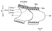
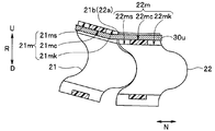
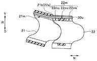
- FIG. 5 is a cross-sectional view showing a state in which the first bending piece is rotated upward to the maximum rotation angle with respect to the second bending piece of FIG. 2
- FIG. 6 is a cross-sectional view of the endoscope of the present embodiment. It is sectional drawing which shows the state which the 1st curved piece rotated upward to the maximum rotation angle with respect to the 2nd curved piece in the curved piece which constitutes a curved part.
- FIG. 7 is a cross-sectional view showing a modified example of the shape of the second groove of the second curved piece of FIG. 6, and FIG. 8 is a modified example of the shape of the first groove of the first curved piece of FIG. It is sectional drawing which shows.
- the configuration of the curved portion, the insertion portion, and the endoscope of the endoscope of the second embodiment has a first groove and a first groove as compared with the first embodiment shown in FIGS. 1 to 4 described above.
- the shape of at least one of the two grooves is different.
- the first groove 21 m with respect to the first curved piece 21 is in the longitudinal axis direction N from the tip end to the base end of the first curved piece 21. It was formed at a constant depth D.
- the second groove 22m with respect to the second curved piece 22 was formed at a constant depth D in the longitudinal axis direction N from the tip end to the base end of the second curved piece 22.
- the depth of the tip portion 21 ms and the base end portion 21 mk in the longitudinal axis direction N is formed deeper than the intermediate portion 21 mc. There is.
- the tip portion 21 ms and the base end portion 21 mk are formed thinner than the intermediate portion 21 mc.
- the tip portion 21 ms and the base end portion 21 mk are formed outside the intermediate portion 21 mc in the radial direction R, and the tip portion 21 ms, the base end portion 21 mk, and the intermediate portion 21 mc are formed.
- An inclined surface is formed between the two.
- the depth of the tip portion 22 ms and the base end portion 22 mk in the longitudinal axis direction N is formed deeper than the intermediate portion 22 mc.
- the tip portion 22 ms and the base end portion 22 mk are formed thinner than the intermediate portion 22 mc.
- the tip portion 22 ms and the base end portion 22 mk are formed inside the intermediate portion 22 mc in the radial direction R, and the tip portion 22 ms, the base end portion 22 mk, and the intermediate portion 22 mc are formed.
- An inclined surface is formed between the two.
- the second groove 22m is formed at a constant depth D along the longitudinal axis direction N, and only the first groove 21m is formed in the same shape as in FIG.
- the first groove 21 m is formed at a constant depth D along the longitudinal axis direction N, and only the second groove 22 m is formed in the same shape as in FIG. It doesn't matter.
- the first curved piece 21 and the shoulder portion 22a shoulder the second curved piece 22. It rotates upward (U) up to the maximum rotation angle that abuts on the portion 21b. At this time, at the contact portion between the shoulder portion 22a and the shoulder portion 21b, the first groove 21m and the second groove 22m are bent into the wire 30u as shown in FIG. The portion T is not formed. Therefore, it is possible to prevent the wire 30u from being damaged.
- the wire 30u can move smoothly in the longitudinal axis direction N, so that the maximum rotation angle can be easily reached until the shoulder portion 22a and the shoulder portion 21b come into contact with each other. Since it can rotate, a desired bending shape and bending angle can be obtained with respect to the curved portion 11.
- FIG. 9 is a cross-sectional view showing a modified example in which each tip end portion and each base end portion in the first groove of the first curved piece and the second groove of the second curved piece of FIG. 6 are notched.
- FIG. 10 is a cross-sectional view showing a modified example in which each tip end portion and each base end portion in the first groove of the first curved piece and the second groove of the second curved piece of FIG. 7 are notched.
- FIG. 11 is a cross-sectional view showing a modified example in which each tip end portion and each base end portion in the first groove of the first curved piece and the second groove of the second curved piece of FIG. 8 are notched.
- the tip portion 21 ms and the base end portion 21 mk of the first groove 21 m in the first curved piece 21 are made deeper than the intermediate portion 21 mc, and the second curved piece 22
- the configuration in which the tip portion 22 ms and the base end portion 22 mk of the second groove 22 m are deeper than the intermediate portion 22 mc is a configuration in which the first curved piece 21 and the second curved piece 21 and the second curved piece are as shown in FIGS. 6 to 8 described above.
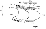
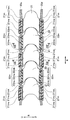
- FIG. 12 is a partial cross-sectional view showing a plurality of curved pieces constituting the curved portion of the present embodiment together with two wires
- FIG. 13 is a cross-sectional view of the first curved piece along the line XIII-XIII in FIG. Is shown side by side with the cross section of the second curved piece along the XIII'-XIII' line in FIG. 12 together with the wire.
- the configuration of the curved portion, the endoscope insertion portion, and the endoscope of the endoscope of the third embodiment is shown in the first embodiment shown in FIGS. 1 to 4 and FIGS. 5 to 11 described above.
- the shapes of the first groove and the second groove are different from those of the second embodiment.
- the length Z in the radial direction R between the bottoms is smaller than the outer diameter K of the wires 30u and 30d.
- the positions of the wires 30u and 30d in the radial direction R are higher than those of the first groove 21m. It is located outside the radial direction R in the groove 22 m of 2.
- first groove 21m and the second groove 22m are formed at a constant depth D along the longitudinal axis direction N, or as shown in FIG. 12, the first groove. Even when the tip portion 21 ms and the base end portion 21 mk are formed deeper than the intermediate portion 21 mc at 21 m, and the tip portion 22 ms and the base end portion 22 mk are formed deeper than the intermediate portion 22 mc in the second groove 22 m. The same is true.
- the wires 30u and 30d inserted into the first groove 21m and the second groove 22m along the longitudinal axis direction N meander along the longitudinal axis direction N.
- the meandering wires 30u and 30d tend to return to the shape along the longitudinal axis direction N, so that the first groove 21m Since it is pressed against each bottom of the second groove 22 m in the radial direction R, it becomes more difficult to move to the outside or the inside of the radial direction R than in the configurations of the first and second embodiments.
- the friction on the bottoms of the first groove 21m and the second groove 22m increases, so that the curved portion 11 is curved upward (U) or downward (D).
- the curved shape can be easily fixed without using a known shape locking mechanism separately provided in the operation unit 3, so that the manufacturing cost can be reduced.
- the operator can fix the bending shape of the bending portion 11 even if the finger is released from the bending operation lever 15, so that the operated bending is performed. Since it is not necessary to keep pressing the operation lever 15 with the fingers, the burden on the fingers can be reduced.
- the curved portion 11 is shown to be bendable in the vertical direction by the wires 30u and 30d, but the curved portion 11 may be bendable in the horizontal direction. ..
- the first groove 21m is formed at two positions so as to face the inner circumference 21n of the first curved piece 21 at a position corresponding to the left-right direction in the circumferential direction of the first curved piece 21.
- the second groove 22m is formed at two positions so as to face the outer circumference 22g of the second curved piece 22 at a position corresponding to the left-right direction in the circumferential direction of the second curved piece 22.
- the curved portion 11 may be freely curved in the vertical and horizontal directions by the four wires.
- the first groove 21m is located at a position corresponding to the vertical and horizontal directions in the circumferential direction of the first curved piece 21 with respect to the inner circumference 21n of the first curved piece 21, approximately every 90 ° in the circumferential direction.
- the second groove 22 m is formed at four locations in the circumferential direction, and the second groove 22 m is located at a position corresponding to the vertical and horizontal directions in the circumferential direction of the second curved piece 22 with respect to the outer circumference 22 g of the second curved piece 22. It is formed at 4 points every °.
- the first curved piece 21 and the second curved piece 22 are shown to be made of resin, but they may be made of metal. ..
- the first curved piece 21 and the second curved piece 22 are made of resin, and the curved portion 11 has a smaller diameter.
- the configuration of the first to third embodiments described above is more effective in the conversion.
- first curved piece 21 and the second curved piece 22 are connected by a rivetless structure, but the present invention is not limited to this. It goes without saying that the above-described configurations of the first to third embodiments can be applied to the rivet structure.
- first bending piece 21 and the second bending piece 22 are alternately arranged in the longitudinal axis direction N, but the present invention is limited to this. However, as long as the curved shape of the curved portions 11 as described above does not become unstable, they do not necessarily have to be arranged alternately.
- the first curved piece 21, the first curved piece 21, the second curved piece 22, the second curved piece 22, the first curved piece 21, and so on are arranged along the longitudinal axis direction N. It doesn't matter if you do.
- the endoscope 1 is shown by taking a renal pelvis ureteroscope as an example, but it goes without saying that the endoscope 1 is not limited to the renal pelvis ureteroscope. In particular, it is desirable to apply it to endoscopes that require smaller diameters and lower manufacturing costs.
- FIG. 14 is a partial cross-sectional view of a curved portion of a general endoscope.
- the first groove 21m is formed so as to penetrate the entire length from the tip end to the base end of the first curved piece 21 in the longitudinal axial direction N.
- the second groove 22m is also formed so as to penetrate in the longitudinal axis direction N over the entire length from the tip end to the base end of the second curved piece 22.
- this can also be applied to the through holes 41v and 42v formed in the wire receivers of the bending pieces 41 and 42 constituting the curved portion of a general endoscope.
- the through hole 41v is formed in the wire receiver along the longitudinal axial direction N over the entire length from the tip end to the base end of the curved piece 41, and the through hole 42v has the entire length from the tip end to the base end of the curved piece 42. It is formed in the wire receiver along the longitudinal axis direction N.
- the shoulder space N1 between the curved pieces 41 in the longitudinal axis direction N1, the shoulder space N2 between the curved piece 41 and the curved piece 42 in the longitudinal axis direction N, and the shoulder space N3 between the curved pieces 42 in the longitudinal axis direction are through holes.
- the wires 30u and 30d are inserted through the first groove 21m and the through holes 41v and 42v from the front or the rear in the longitudinal axis direction N, rather than the configuration in which the holes 41v and 42v are partially formed. Easy to insert.
- the outer periphery of the curved pieces 41 and 42 is covered with a known blade.
- the outer periphery of the blade may be coated with the heat shrink tube 40.
- this configuration can also be applied to the first to third embodiments described above, and if the outer periphery of the first curved piece 21 and the second curved piece 22 is covered with a heat shrinkable tube, It is possible to effectively prevent the first curved piece 21 and the second curved piece 22 from being displaced in the radial direction R.
- the curved pieces adjacent to each other in the longitudinal axis direction of the endoscope insertion portion are formed in a semicircular (fan-shaped) recess formed at the end of one of the curved pieces.
- a rivetless connection configuration of a curved piece that only abuts a semicircular (fan-shaped) convex portion formed on the end of the other curved piece is well known, and is disclosed in, for example, US Pat. No. 8,465,420.
- a force may be applied to the curved portion not only in the longitudinal axis direction but also in the radial direction of the longitudinal axis, or a torsional force may be applied.
- This configuration provides a curved portion configuration that can prevent vertical displacement and twisting of a plurality of connected curved pieces.
- FIGS. 15 to 17 is a partial cross-sectional view showing a plurality of curved pieces constituting the curved portion of the present configuration
- FIG. 16 is a perspective view of one curved piece of FIG.
- FIG. 17 is a perspective view of the other curved piece of FIG. be.
- the curved piece 51 extends to the base end surface, which is the end of the insertion portion in the longitudinal axis direction N, to the rear in the longitudinal axis direction N, and is a pair symmetrical to the central axis of the curved piece 51. It has a convex portion 51t.
- the convex portion 51t has a semicircular shape (fan shape).
- the curved piece 51 has a pair of recesses 51h that are recessed rearward in the longitudinal axis direction N and symmetrical to the central axis of the curved piece 51 on the tip surface which is the end portion in the longitudinal axis direction N.
- the recess 51h has a semicircular shape (fan shape).
- the curved piece 52 has a pair of convex portions 52t that extend rearward in the longitudinal axis direction N and are symmetrical to the central axis of the curved piece 52 on the base end surface that is the end portion in the longitudinal axis direction N. There is.
- the convex portion 52t has a semicircular shape (fan shape).
- the curved piece 52 has a pair of recesses 52h that are recessed rearward in the longitudinal axis direction N and symmetrical to the central axis of the curved piece 52 on the tip surface which is the end portion in the longitudinal axis direction N.
- the recess 52h has a semicircular shape (fan shape).
- the pair of convex portions 51t of the curved piece 51 are in contact with the pair of concave portions 52h of the curved piece 52.
- the contact between the curved piece 51 and the curved piece 52 is compressed in the longitudinal axis direction N by a wire (not shown) inserted into the through holes 51v and 52v of the wire receivers provided in the curved pieces 51 and 52, respectively. It is done in the state of.
- the curved piece 51 and the curved piece 52 are configured to be rotatable with each other. Specifically, the curved piece 51 and the curved piece 52 are in contact with each other so as to be rotatable in the vertical direction (UD) in the radial direction R of the longitudinal axis N.
- the maximum rotation angle of the pair of convex portions 51t in contact with the pair of concave portions 52h in the upward direction (U) is such that the shoulder portion 52a at the tip of the curved piece 52 and the shoulder portion at the base end of the first curved piece 21. It is defined by the contact of 51b.
- the maximum rotation angle of the pair of convex portions 51t in the downward direction (D) that abuts on the pair of concave portions 52h is defined by the shoulder portion 51b abutting on the shoulder portion 52a.
- the curved portion of this configuration has a known rivetless structure in which rivets are not used to connect the curved pieces 51 and 52 to each other.
- the convex portion 51t bites into the concave portion 52h as much as possible and comes into contact with the concave piece 52h.
- the center point (radial center) 51 tk when the radius of the fan shape of the convex portion 51 t of the curved piece 51 is J is the shoulder of the curved piece 52 in the radial direction R. It is configured on the same plane as the portion 52a.
- the center point 51 tk is located on the same plane as the central axis of the curved pieces 51 and 52 in the longitudinal axis direction.
- the center of radius of the convex portion 52t of the curved piece 52 is also configured in the same manner.
- the above configuration can also be applied to a configuration in which a convex portion 52t is provided at the tip of the curved piece 52 and abuts on a concave portion 51h provided at the base end of the curved piece 51.
- the convex portion 52t does not bite too much into the concave portion 51h and bites into the concave portion 51h with an appropriate contact amount to come into contact with the concave piece 51h, so that the connected curved pieces 51 and 52 may be displaced in the vertical direction. Since it is possible to reliably prevent twisting, the curvature of the curved portion is not hindered.
- the convex portion 51t, the concave portion 51h, the convex portion 52t, and the concave portion 52h are formed in a semicircular shape (fan shape).
- the convex portion 51t is formed in a conical shape in which the surface abutting the concave portion 52h is not a surface substantially perpendicular to the longitudinal axes of the curved pieces 51 and 52 but is abutting diagonally.
- the concave portion 52h may also be formed in a conical shape in which the surface with which the convex portion 51t abuts is obliquely abutted according to the shape of the convex portion 51t.
- the outer diameters of the concave portions 52h and 51h are formed larger than the outer diameters of the convex portions 51t and 52t.
- the convex portion 52t and the concave portion 51h may also be formed in the same shape as the convex portion 51t and the concave portion 52h.
- the distal bending piece is provided at the proximal end bending piece to which the tip of the passive bending portion is connected while being located at the proximal end side in the longitudinal axis direction of the endoscope insertion portion.
- the wire through hole of the wire receiver is generally arranged inside the wire through hole of the wire receiver of the other curved piece in the radial direction on the longitudinal axis of the insertion portion.
- the wire through hole of the base end curved piece is located inside the wire through hole of the curved piece immediately before the base end through hole in the radial direction, the wire is inserted into the wire through hole of each curved piece. At that time, the wire may meander greatly between the base end curved piece and the immediately preceding curved piece, and the wire may be broken.
- the present configuration of the endoscope aims to reduce the meandering of the wire between the bending piece located at the base end of the active bending portion and the bending piece immediately before the bending piece.
- a curved portion configuration is provided.
- FIG. 18 is a partial cross-sectional view of the connecting portion between the active bending portion and the passive bending portion in the bending portion of the present configuration.
- the curved portion of the endoscope is composed of an active curved portion (hereinafter, simply referred to as a curved portion) 11 and a passive curved portion 12.
- the curved portion 11 is configured to be bendable in two directions, for example, in the vertical direction, as the wires 30u and 30d are pulled.
- the curved portion 11 may be configured to be bendable in two directions in the left-right direction, or may be configured to be bendable in four directions of up, down, left, and right.
- the curved portion 11 is configured by connecting a plurality of curved pieces 61 in the longitudinal axis direction N of the insertion portion.
- a reference numeral 62 is attached to a curved piece located on the proximal end side of the plurality of connected curved pieces.
- the passive bending portion 12 is made of a known flex or the like, and is flexibly configured so that it can be passively bent by an external force.
- a wire receiver is formed on the tip end side of each curved piece 61, and a through hole 61v is formed in each wire receiver. Further, a wire receiver is also formed on the base end side of each curved piece 62, and a through hole 62v is formed in the wire receiver.
- the meandering of the wires 30u and 30d described above generated in the W between the curved piece 62 and the curved piece 61 in the longitudinal axis direction N is caused by the through hole 62v and one of the curved piece 62. This can be reduced because the through holes 61v of the previous curved piece 61 are arranged at a large distance in the longitudinal axis direction N.
- various built-in units such as an imaging unit, a lighting unit, and a treatment tool channel are arranged inside the tip of the insertion portion.
- Each of these various built-in units is fixed at a predetermined position with respect to the tip hard member constituting the tip of the endoscope, for example, by using an adhesive or the like.
- a very small lighting lens is placed at the tip of the tip hard member. It is arranged at a predetermined position near the surface. After that, the tip of the light guide cable is arranged at a predetermined position in contact with the illumination lens incorporated in the hard tip member.
- the relative positional relationship between the illumination lens and the tip of the light guide cable is strictly defined. For this reason, high-precision incorporating technology is required for the incorporation of the lighting unit.
- This configuration was made in view of the above points, and the purpose is to simplify the work process when incorporating various built-in units arranged inside the tip of the endoscope into the hard tip member. It is an object of the present invention to provide an endoscope tip portion having a structure capable of ensuring highly accurate and stable incorporation accuracy.
- the endoscope tip portion of one aspect of the present configuration is formed in a substantially tubular shape and covers the outer surface of the endoscope tip portion, and inside the endoscope tip portion.
- the plurality of built-in units When the plurality of built-in units are fixed at each predetermined position, the plurality of built-in units have a notch portion that exposes a part of each of the plurality of built-in units to the outside.
- FIG. 19 to 21 are diagrams showing a fourth embodiment of the present configuration.
- FIG. 19 is an enlarged perspective view of a main part showing an enlarged schematic configuration of the tip of the endoscope according to the present embodiment.
- FIG. 20 is a side view of the tip of the endoscope of FIG.
- FIG. 21 is an exploded perspective view showing a state in which the tip cover is removed at the tip of the endoscope in FIG.
- various built-in units such as an imaging unit 201, a lighting unit 202, and a treatment tool channel 203 are built and fixed in the tip portion 10 of the endoscope having this configuration.
- the tip hard member 200 is arranged.
- the tip rigid member 200 is configured as a two-body structure of the tip cover member 10a and the tip base member 10b.
- the tip cover member 10a is a frame component that is formed in a substantially cylindrical shape and covers the outer surface of various built-in units when the tip base member 10b is loaded inside. As shown in FIG. 21, an observation window 10aa, an illumination window 10ab, and a channel opening 10ac are formed on the tip surface of the tip cover member 10a. In this embodiment, two lighting windows 10ab are provided. In this case, the two illumination windows 10ab are arranged so as to sandwich the observation window 10aa in the vicinity of the periphery of the observation window 10aa.
- the tip base member 10b is a base member that integrates a plurality of built-in units (201, 202, 203) built in the tip 10 in the vicinity of each tip in a fixed state.
- the tip base member 10b is loaded inside the tip cover member 10a after the plurality of built-in units (201, 202, 203) are fixed and integrated. Then, the tip base member 10b is, for example, adhesively fixed in a state of being loaded at a predetermined position inside the tip cover member 10a.
- the image pickup unit 201 is composed of, for example, an image pickup element such as a CCD or CMOS, an image pickup board on which a drive circuit for driving the image pickup element, or the like is mounted, and an image pickup signal cable extending from the image pickup board.
- an image pickup element such as a CCD or CMOS
- an image pickup signal cable extending from the image pickup board.
- the lighting unit 202 is mainly composed of a lighting lens 202a and a light guide cable 202b.
- the illumination lens 202a is provided so as to obtain a predetermined light distribution when irradiating the illumination light guided by the light guide cable 202b from a light source device (not shown) toward the front of the tip portion 10. It is an optical lens.
- the illumination lens 202a is fixed at a predetermined position on the tip base member 10b. Then, when the tip base member 10b is loaded into the tip cover member 10a, the illumination lens 202a is arranged in the illumination window 10ab of the tip cover member 10a.
- the light guide cable 202b is an optical fiber cable for guiding the illumination light from a light source device (not shown) to the tip portion 10.
- the light guide cable 202b is fixed at a predetermined position of the tip base member 10b in a state where the tip surface thereof is arranged at a position facing the illumination lens 202a.
- One end of the treatment tool channel 203 is connected to the treatment tool insertion port (not shown) of the operation unit (not shown in FIG. 19 and the like) of the endoscope, and the other end is the tip base of the tip portion 10 of the endoscope. It is a tubular member that is inserted and arranged inside an insertion portion of an endoscope in a state of being fixed at a predetermined position of the member 10b. Various predetermined treatment tools inserted from the treatment tool insertion port are inserted into the treatment tool channel 203. Then, the tip of the treatment tool inserted into the treatment tool channel 203 projects forward from the channel opening 10ac on the front surface of the tip cover member 10a of the tip portion 10.
- the tip base member 10b is formed with a plurality of receiving portions (10ba, 10bb, 10bc) for arranging and fixing a part in the vicinity of each tip portion of various built-in units (201, 202, 203). That is, there are a receiving unit 10ba in which the imaging unit 201 is arranged, a receiving unit 10bb in which the lighting unit 202 is arranged, and a receiving unit 10bc in which the treatment tool channel 203 is arranged. Since the present embodiment is a configuration example in which two lighting units 202 are arranged, two receiving units 10bb corresponding to the lighting unit 202 are also provided. These two receiving portions 10bb are arranged so as to sandwich the receiving portion 10ba corresponding to the image pickup unit 201. Then, when each predetermined built-in unit is fixed to each of these plurality of receiving portions (10ba, 10bb, 10bc), a notch for exposing a part of each built-in unit to the outside is formed. The part is formed.
- a wire fixing portion 204 for fixing the tip of the curved wire 30 is formed at a predetermined portion of the tip base member 10b.
- the wire fixing portion 204 is formed to have a groove through which the curved wire 30 is inserted and a storage chamber for accommodating the spherical locking member 30a fixed to the tip of the curved wire 30.
- the wire fixing portion 204 shows a configuration example provided on the outer peripheral surface of the tip base member 10b near the base end.
- the curved wire 30 is a towing wire for curving the direction in which the tip surface of the tip of the insertion portion of the endoscope faces, for example, in two directions of left / right or up / down or in four directions of up / down / left / right. Therefore, two or four curved wires 30 are arranged.
- an example in which two curved wires 30 are provided is shown.
- FIGS. 19 to 21 only one curved wire 30 is shown, and the other one is arranged at a hidden position.
- the tip cover member 10a and the tip base member 10b are formed by using, for example, a resin material having an insulating property.
- the endoscope tip portion 10 configured as described above is roughly assembled as follows. First, various built-in units (201, 202, 203) are incorporated into the tip base member 10b at predetermined positions in a predetermined form.
- the imaging unit 201 is arranged on the receiving portion 10ba of the tip base member 10b, and is adhered using, for example, an ultraviolet curable adhesive. At this time, for example, the light receiving surface of the imaging unit 201 is arranged so as to be flush with the tip surface of the receiving portion 10ba.
- the tips of the two lighting units 202 are arranged on the two receiving portions 10bb of the tip base member 10b, and are bonded using, for example, an ultraviolet curable adhesive.
- the illumination lens 202a is arranged and adhered to the tip portion of each receiving portion 10bb of the tip base member 10b.
- the optical axis (not shown) of the illumination lens 202a is arranged so as to be substantially orthogonal to the tip surface of the receiving portion 10bb.
- the tip surface of the light guide cable 202b is arranged and adhered so as to face the illumination lens 202a already fixed at a predetermined position of the tip base member 10b.
- the optical axis of the illumination lens 202a and the illumination optical axis of the light guide cable 202b are arranged so as to substantially coincide with each other.
- the tip of the treatment tool channel 203 is arranged on the receiving portion 10bb of the tip base member 10b and adhered using, for example, an ultraviolet curable adhesive.
- each of these various built-in units (201, 202, 203) is arranged with respect to each predetermined receiving portion (10ba, 10bb, 10bc) of the tip base member 10b, the built-in unit (201, 202, 203) A part of each is exposed to the outside from the notch. Therefore, the operator can easily confirm during the work whether or not each of the built-in units (201, 202, 203) is arranged at a predetermined position on the tip base member 10b in a predetermined state. can.
- the operator can proceed with the work while checking the assembling state during the work of assembling each built-in unit (201, 202, 203) to the tip base member 10b, so that the assembling work is always reliable and accurate. be able to.
- the tip base member 10b in which each built-in unit (201, 202, 203) is assembled and integrated is loaded at a predetermined position inside the tip cover member 10a, and for example, an ultraviolet curable adhesive or the like is used. And glue.
- the tip cover member 10a and the tip base member 10b are assembled as a tip hard member 200 in an integrated state.
- the tip hard member 200 is composed of two parts, the tip cover member 10a and the tip base member 10b, and various built-in units (201) are previously provided for the tip base member 10b. , 202, 203), and then the integrated tip base member 10b is assembled to the tip cover member 10a. Therefore, while ensuring assembly accuracy, complicated work can be simplified and work efficiency can be achieved. Can contribute to the improvement of.
- the work can proceed while checking the assembling state of each unit. Therefore, it is possible to ensure reliable and accurate assembly work at all times, and thus it is possible to maintain high-precision assembly at all times and contribute to an improvement in yield.
- FIG. 22 to 24 are diagrams showing a fifth embodiment of the present configuration.
- FIG. 22 is an enlarged perspective view of a main part showing an enlarged schematic configuration of the tip of the endoscope according to the present embodiment.
- FIG. 23 is a side view of the tip of the endoscope in FIG. 22.
- FIG. 24 is an exploded perspective view showing a state in which the tip cover is removed at the tip of the endoscope in FIG. 22.
- the basic configuration of this embodiment is substantially the same as that of the fourth embodiment described above.
- the structure of the tip base member 10Ab is slightly different. Therefore, the same configurations as those of the above-described fourth embodiment are designated by the same reference numerals, the description thereof will be omitted, and only the different parts will be described below.
- each of the various built-in units (201, 202, 203) is attached to each receiving portion (10ba, 10bb, 10bc) of the tip base member 10b.
- each receiving portion (10ba, 10bb, 10bc) of the tip base member 10b When arranging and fixing, a part near each tip of various built-in units was fixed.
- the configurations of the tip cover member 10Aa constituting the tip rigid member 200A and the cable holding portion 10Aba are slightly different.
- the tip cover member 10Aa is formed so that a part of the tip cover member 10Aa protrudes from the base end surface toward the base end side, and a protective wall 10Aaa is provided to cover and protect a part of the outer peripheral surface.
- the protective wall 10Aaa is formed so as to mainly cover the side surface of the lighting unit 202. Therefore, the protective wall 10Aaa has a function of blocking unnecessary light leaking from the light guide cable 202b of the lighting unit 202 toward the side or the like.
- the tip base member 10Ab is configured by providing a cable holding portion 10Aba on the base end side in addition to a configuration in which a part in the vicinity of the tip portion is adhesively fixed (similar to the configuration of the fourth embodiment).
- the cable holding portion 10Aba includes various cables (for example, imaging signal cable 201a, light guide cable 202b, etc.) extending from various built-in units (201, 202) toward the rear (base end side), and a treatment tool channel 203. It is a component that holds and in a bundled form.
- the cable holding portion 10Aba is integrally formed at a portion of the tip base member 10Ab near the base end, and is formed in, for example, an annular shape.
- a wire fixing portion 204A for fixing the tip of the curved wire 30 is formed on the outer peripheral surface side of the cable holding portion 10Aba.
- the wire fixing portion 204A is formed as having a groove through which the curved wire 30 is inserted and a storage chamber for accommodating the tip spherical locking member 30a of the curved wire 30, as in the fourth embodiment. be.
- the wire fixing portion 204A is formed by cutting out the cable holding portion 10Aba of the tip base member 10Ab, and the curved wire 30 and the tip spherical locking member 30a are embedded in the cable holding portion 10Aba. It differs in that it is formed to be arranged. Other configurations are the same as those in the fourth embodiment described above.
- the imaging signal cable 201a extending from the imaging unit 201 and the lighting unit 202
- the extending light guide cable 202b, the treatment tool channel 203, and the cable holding portion 10Aba are inserted from the base end side to the tip end side.
- a part of the various built-in units (201, 202, 203) near the tip is adhesively fixed.
- the subsequent assembly work procedure is the same as that of the fourth embodiment described above.
- the same effect as that of the fourth embodiment can be obtained.
- the protective wall 10Aaa is provided on the tip cover member 10Aa, it is possible to block unnecessary light leaking from the light guide cable 202b. Therefore, it is possible to suppress an adverse effect on the video data acquired by the imaging unit 201.
- the imaging signal cable 201a and the light guide cable 202b extending rearward from various built-in units and the treatment tool channel 203 are bundled. Can be held at.
- the various cables (201a, 202b) and the treatment tool channel 203 are adhesively fixed at the tip end side and held by the cable holding portion 10Aba at the base end side. Therefore, various cables (201a, 202b) and the treatment tool channel 203 can be fixed to the tip base member 10Ab (tip hard member 200A) in a more stable form.
- the wire fixing portion 204A is configured so as to embed the curved wire 30 and the tip spherical locking member 30a in the cable holding portion 10Aba of the tip base member 10Ab, the wire fixing portion protrudes in the radial direction. Can be deterred. Therefore, it is possible to contribute to reducing the diameter of the tip hard member 200A.
- various built-in units such as an imaging unit, a lighting unit, and a treatment tool channel are arranged inside the tip of the insertion portion.
- Each of these various built-in units is fixed at a predetermined position with respect to the tip hard member constituting the tip of the endoscope, for example, by using an adhesive or the like.
- the lighting unit is generally composed of a lighting lens, a light guide cable, and the like.
- the light guide cable is extended from the universal cable through the inside of the operation unit and the endoscope insertion unit to the tip of the endoscope, and the illumination light emitted from the light source device to which the universal cable connector is connected.
- the illumination light guided to the tip of the endoscope is configured to be emitted from the front window of the tip of the endoscope toward the front of the endoscope.
- the light guide cable is used at the tip of the endoscope.
- an endoscope at a position facing the most advanced surface, for example, in which an optical lens having a predetermined shape (for example, concave shape or convex shape) is provided on a front window at the tip of the endoscope.
- a member for fixing a light guide cable for example, a predetermined portion of a hard tip member (that is, a position facing the tip surface of the light guide cable) of an optical lens.
- An endoscope that is integrally configured with a function is considered.
- the member (hard tip member) itself for fixing the light guide cable with a transparent material. Therefore, the illumination light emitted from the light guide cable may enter an unintended direction, for example, the imaging surface of the imaging unit. In this case, the imaging unit has a problem that it cannot acquire a normal image. Therefore, in this type of conventional endoscope, for example, a light-shielding member for suppressing the intrusion of unnecessary light into the imaging unit is required. Therefore, even in this case, there are problems that the manufacturing process is complicated and the manufacturing cost is increased due to the increase in the number of parts.
- the endoscope disclosed in JP-A-09-80324 and the like is large by arranging a plurality of optical fibers around the imaging unit and providing an outward tapered surface on the tip surface of each optical fiber.
- the irradiation angle is obtained to realize a wide range of light distribution.
- the light emitted from the outwardly tapered surface provided on the tip surface of each optical fiber contributes to the expansion of the outward light distribution.
- This configuration was made in view of the above points, and its purpose is to be able to irradiate an observation object in front of the endoscope with sufficient illumination light and to increase the number of parts. It is an object of the present invention to provide an endoscope tip portion having a structure capable of realizing distribution of illumination light over a wider range without accompanying.
- the endoscope tip portion of one aspect of this configuration includes an imaging unit, a plurality of light guides, and a tip rigid member that fixes and holds the imaging unit and the tip of the light guide.
- the plurality of light guides have a tip shape of a convex sphere facing forward or a concave shape facing backward.
- FIG. 25 to 27 are diagrams showing the sixth embodiment of this configuration.
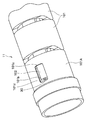
- FIG. 25 is an enlarged external perspective view of a main part showing the appearance of the tip of the endoscope according to the present embodiment.
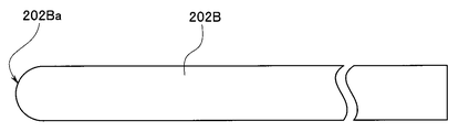
- FIG. 26 is a side view showing the vicinity of the tip of a light guide cable applied to the tip of the endoscope of the present embodiment.
- FIG. 27 is a side view showing the vicinity of the tip of another form of the light guide cable applied to the tip of the endoscope of the present embodiment.
- the tip portion 10B is a tip frame member that is a tip frame member that incorporates and fixes various built-in units such as an image pickup unit 201, a light guide cable 202B that is a lighting unit, and a treatment tool channel 203.
- the member 200B is arranged.
- the tip hard member 200B is a frame component that is formed in a substantially cylindrical shape and in which various built-in units are arranged. As shown in FIG. 25, an observation window 10aa, an illumination window 10ab, and a channel opening 10ac are formed on the tip surface of the tip rigid member 200B. In this embodiment, two lighting windows 10ab are provided. In this case, the two illumination windows 10ab are arranged so as to sandwich the observation window 10aa in the vicinity of the periphery of the observation window 10aa.
- the image pickup unit 201 is adhesively fixed inside the observation window 10aa. Further, the tip portion of the light guide cable 202B is adhesively fixed to the inside of the illumination window 10ab. Further, the tip portion of the treatment tool channel 203 is adhesively fixed inside the channel opening 10ac.
- the image pickup unit 201 is composed of, for example, an image pickup element such as a CCD or CMOS, an image pickup board on which a drive circuit for driving the image pickup element, or the like is mounted, and an image pickup signal cable extending from the image pickup board.
- an image pickup element such as a CCD or CMOS
- an image pickup signal cable extending from the image pickup board.
- the lighting unit is configured by using the light guide cable 202B.
- the light guide cable 202B is formed so that the shape of the tip portion thereof is a convex spherical shape (hereinafter, simply referred to as a convex shape) 202Ba facing forward.
- the "front” refers to, for example, the tip side (the side closer to the tip) of the insertion portion in the endoscope.
- the light guide cable 202B is an optical fiber cable for guiding the illumination light from a light source device (not shown) to the tip portion 10B.
- the tip of the light guide cable 202B is formed in a convex shape 202Ba. With such a shape, it is possible to obtain a predetermined light distribution when irradiating the illumination light guided by the light guide cable 202B from a light source device (not shown) toward the front of the tip portion 10B. can.
- the tip of the light guide cable 202B is formed so as to have a convex shape 202Ba. A predetermined front light distribution can be obtained.
- One end of the treatment tool channel 203 is connected to the treatment tool insertion port (not shown) of the operation portion (not shown) of the endoscope, and the other end is inside the tip hard member 200B of the tip portion 10B of the endoscope. It is a tubular member that is inserted and arranged inside an insertion portion of an endoscope in a state of being fixed at a predetermined position.
- Various predetermined treatment tools inserted from the treatment tool insertion port are inserted into the treatment tool channel 203. Then, the tip of the treatment tool inserted into the treatment tool channel 203 projects forward from the channel opening 10ac on the front surface of the tip rigid member 200B of the tip portion 10B.
- the tip of the light guide cable 202B constituting the lighting unit is adhesively fixed at a predetermined position inside the tip hard member 200B. Then, in the present embodiment, as shown in FIG. 25, two light guide cables 202B are provided. Here, these two light guide cables 202B are arranged so as to sandwich the image pickup unit 201.
- the advanced hard member 200B of the present embodiment is colored (for example, black) other than transparent in order to block the leakage of this kind of unnecessary light.
- Other configurations are the same as those of the conventional endoscope tip.
- the shape of the tip of the light guide cable 202B constituting the lighting unit is a convex shape 202Ba, so that the lighting lens can be formed without providing the lighting lens. It is possible to configure a lighting unit having the same function as the configuration when used, that is, a lighting unit having a desired light distribution characteristic. For example, according to the above configuration, a wider range of light distribution can be obtained without using an illumination lens.
- the number of parts can be reduced, which can contribute to the simplification of the assembly process and the reduction of the manufacturing cost.
- the shape of the tip of the light guide cable 202B is not limited to the convex shape 202Ba as in the above-described configuration, and the shape of the tip of the light guide cable 202B may be appropriately redesigned. Therefore, a desired light distribution can be obtained.
- the shape of the tip of the light guide cable 202B may be a concave shape 202Bb facing rearward.
- the "rear" means, for example, the proximal end side (the side closer to the operating portion) of the insertion portion in the endoscope. Even with such a configuration, desired light distribution characteristics can be obtained.
- various built-in units such as an imaging unit 201 and a lighting unit (light guide cable 202B) are contained inside the tip rigid member 200B.
- the treatment tool channel 203 and the like are arranged (see FIG. 25 and the like).
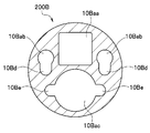
- FIG. 28 is a cross-sectional view of the cut surface shown by the alternate long and short dash line in FIG. 25 as viewed from the direction of the arrow [28].
- the tip rigid member 200B is formed with a plurality of arrangement portions (10Baa, 10Bab, 10Bac) having a shape corresponding to each of the various built-in units.
- the portion indicated by reference numeral 10Baa is an arrangement portion for arranging the imaging unit 201. Further, the portion indicated by the reference numeral 10Bab is an arrangement portion (plurality) for arranging the lighting unit 202. The portion indicated by reference numeral 10Bac is an arrangement portion for arranging the treatment tool channel 203.
- These plurality of arrangement portions (10Baa, 10Bab, 10Bac) communicate with the observation window 10aa, the illumination window 10ab, and the channel opening 10ac provided on the tip surface of the tip rigid member 200B, and are through holes toward the rear (closer to the base end). It is formed in a shape.
- the outer surface of the image pickup unit 201 and the inner surface of the arrangement portion 10Baa are adhesively fixed in a state where the image pickup unit 201 is arranged on the arrangement portion 10Baa.
- the outer surface of the light guide cable 202B and the inner surface of the arrangement portion 10Bab are adhesively fixed.
- the outer surface of the treatment tool channel 203 and the inner surface of the arrangement portion 10Bac are adhesively fixed.
- the adhesive applied in this case is, for example, an ultraviolet curable adhesive.
- the light guide cable 202B and the treatment tool channel 203 are members formed in an elongated tube shape. Therefore, for example, the inner diameter of the arrangement portion 10Bab is set to be slightly larger than the outer diameter of the light guide cable 202B. Further, for example, the inner diameter of the arrangement portion 10Bac is set to be slightly larger than the outer diameter of the treatment tool channel 203.
- An adhesive storage portion 10Be is formed at a portion communicating with the adhesive storage portion 10Be.
- the adhesive storage portions 10Bd and 10Be are formed in a groove shape that communicates from the base end side to the tip end side of the tip hard member 200B.
- the adhesive storage portions 10Bd and 10Be are provided for the predetermined arrangement portions 10Bab and 10Bac to form the adhesive storage portions 10Bd and 10Be, so that a larger amount of adhesive is applied. can do. Therefore, when various built-in units are bonded and fixed inside the tip rigid member 200B, the bonding can be performed more firmly and in a short time.
- various constituent units are arranged inside the operation unit of the endoscope, for example, various cables (imaging signal cable, light guide cable, curved wire, etc.) extending from the insertion unit and various types.
- Tubular members suction pipes, air supply and water supply pipes, etc.
- These cables and tubular members are inserted into the operation unit and then extended to the universal cable.
- the operation unit is provided with a treatment tool insertion port.
- a treatment tool channel communicates with the treatment tool insertion port.
- Various treatment tools inserted from the treatment tool insertion port are inserted and arranged in the treatment tool channel.
- the following structure is provided as a device for avoiding interference between various constituent units arranged inside.
- FIG. 29 is a schematic perspective view showing a part of the internal structure of the endoscope operation unit. Note that FIG. 29 omits the illustration of various constituent units arranged inside the operation unit, and shows only a part of the housing unit constituting the operation unit.
- the arrangement paths of various cables (imaging signal cable, light guide cable, etc .; not shown) that pass through the inside of the operation unit 3 are secured, and these are secured.
- a plurality of ribs 3a, 3b, 3c which are structures for preventing interference between various cables and other built-in objects (not shown), are provided.
- the plurality of ribs 3a, 3b, 3c are thin plate wall-shaped portions having one or a plurality of portions whose cross sections are formed in a substantially concave shape. As shown in FIG. 29, the ribs 3a, 3b, and 3c are shown with different reference numerals because their shapes are slightly different.
- the structure of the rib basically needs to have a portion where the cross section is formed in a substantially concave shape as described above, and the number of the substantially concave portion and the overall shape of the rib itself are described. It may be set appropriately according to the corresponding cables and the like.
- these plurality of ribs 3a, 3b, 3c are formed by, for example, integrally molding with the housing member of the operation unit 3.
- the rib 3a is not limited to this configuration, and the rib 3a may be formed of a separate member from the operation unit 3 and may be appropriately arranged at a predetermined position inside the operation unit 3 by adhesion or the like. ..
- These plurality of ribs 3a are arranged along a predetermined arrangement path corresponding to each predetermined cable. Specifically, for example, after inserting an insertion portion (not shown) and extending it to the inside of the operation portion 3, the operation portion 3 is inserted and further into a universal cable (not shown). There are cables that are extended. Of these, for example, the light guide cable or the like is arranged inside the operation unit 3 along, for example, the alternate long and short dash line with the reference numerals L1 and L2 shown in FIG.
- a plurality of ribs 3a are arranged side by side at predetermined intervals along the arrangement path of the light guide cable.
- the light guide cable is inserted between the concave portions of the ribs 3a, so that the arrangement path thereof is secured.
- the light guide cable can avoid interference with other internals.
- rib members having the same shape as the ribs (3a, 3b, 3c) are arranged at corresponding positions, and the cables are arranged along the rib members. The same effect can be obtained by arranging.
- a treatment tool (not shown) is inserted into the treatment tool insertion port 18. Then, the treatment tool inserted from the treatment tool insertion port 18 is configured to be naturally and reasonably inserted into the treatment tool channel.
- the route along the alternate long and short dash line with the reference numeral T shown in FIG. 29 is shown.
- a guide wall 18a is formed to prevent the light guide cable and the like from being pressed by moving in the directions of L1 and L2 where the light guide cable and the like are arranged. Further, a plurality of ribs 18b having substantially the same shape as the ribs 3a are arranged side by side at predetermined intervals along the guide wall 18a.
- FIG. 30 and 31 show a seventh embodiment
- FIG. 30 is a cross-sectional view showing a configuration example in which the sleeve 102 at the tip of the wire 30 is connected to the tip curved piece 101A
- FIG. 31 shows the wire 30 being inserted. It is a perspective view which shows the structural example of the notch hole 101b provided in the tip curved piece 101A for this purpose.
- a plurality of bending pieces 101 are continuously provided in the bending portion 11, and the bending piece 101 located at the most tip is the tip bending piece 101A. Then, for example, a rectangular notch hole 101b is provided in the cylindrical tip curved piece 101A.
- the rear end side (operation unit 3 side) of the wire 30 can be inserted into the hole 101a of the tip curved piece 101A.
- a sleeve 102 is integrally provided on the tip end side of the wire 30 by, for example, swaging.
- the wire 30 can slide and move through the hole 101a.
- the movement of the wire 30 toward the rear end side in the insertion axis direction is restricted by the contact between the sleeve 102 and the outlet end surface 101c of the hole 101a. Further, the movement of the wire 30 toward the tip end side in the insertion axis direction is restricted by the contact between the sleeve 102 and the tip end surface 101d of the notch hole 101b.
- the radial position of the wire 30 in the tip curved piece 101A is the radial position of the wire 30 in the curved piece 101 adjacent to the tip curved piece 101A. It is on the outer diameter side.
- the tip surface 101d can be positioned on the movement path in the insertion axis direction of the sleeve 102 without thickening the portion of the tip surface 101d of the tip bending piece 101A.
- the movement of the wire 30 to the front end side and the rear end side can be regulated by the sleeve 102, so that the sleeve 102 can be prevented from being displaced and the angle of the curve can be lowered. , Curved lock, etc. can be prevented.
- the wire 30 since the movement of the wire 30 toward the tip end side is restricted, the wire 30 does not extend into the tip portion 10, and the wire 30 can be prevented from coming into contact with the internal components of the tip portion 10. can.
- FIG. 32 shows a first modification of the seventh embodiment, in which the sleeve 102 provided at the tip of the wire 30 is heat-welded (fused) to the curved outer skin 103 through the notch hole 101b. It is sectional drawing which shows the structural example.
- the outer peripheral side of the curved portion 11 is covered with a curved portion outer skin 103 made of resin (or rubber or the like).
- the curved portion outer skin 103 is fixed to the curved portion 11 by being heat-welded to the peripheral surface of the tip curved piece 101A.
- the sleeve 102 is integrally fixed to the tip curved piece 101A by heat-welding the curved outer skin 103 to the sleeve 102. Even in this case, the step of fixing the sleeve 102 and the tip curved piece 101A with an adhesive, solder, welding, or the like can be omitted.
- the curved outer skin 103 when the curved outer skin 103 is heat-welded to the peripheral surface of the tip curved piece 101A, it is also heat-welded to the sleeve 102. Therefore, it is possible to more reliably regulate the movement of the sleeve 102 in the insertion axis direction without increasing the number of steps.
- FIG. 33 shows a second modification of the seventh embodiment, and shows a cross section showing a configuration example in which the sleeve 102 provided at the tip of the wire 30 is press-fitted into the mounting hole 101e provided at the tip curved piece 101A. It is a figure.
- the tip curved piece 101A is provided with a mounting hole 101e on the tip side of the hole 101a through which the wire 30 is inserted.
- the mounting hole 101e communicates coaxially with the hole 101a.
- the mounting hole 101e is surrounded by the wall of the tip curved piece 101A, and has a larger diameter than the hole 101a (however, a slightly smaller diameter than the outer diameter of the sleeve 102).
- the length of the mounting hole 101e in the insertion axis direction is, for example, about the same as the length of the sleeve 102 in the insertion axis direction.
- the sleeve 102 is fixed to the tip curved piece 101A by press-fitting the sleeve 102 into the mounting hole 101e (however, the fixing process by adhesive, solder, welding, etc. is omitted). As a result, even if the wire 30 is pulled or loosened, the sleeve 102 does not move from the mounting hole 101e.
- the movement of the sleeve 102 in the insertion axis direction can be more reliably regulated.
- FIG. 34 shows a third modification of the seventh embodiment, and is a configuration example in which the sleeve 102 provided at the tip of the wire 30 is restricted from moving toward the tip side in the insertion axis direction by the regulating member 111. It is a cross-sectional view which shows.
- a tubular regulating member 111 is arranged on the tip end side of the sleeve 102.
- the regulating member 111 is provided on another member located on the tip side of the tip curved piece 101A, and is integrally formed with, for example, the tip rigid portion 150 (see FIG. 51 and the like) in the tip portion 10.
- the regulation member When the rear end surface of the sleeve 102 is in contact with the outlet end surface 101c, the regulation member is kept at a predetermined distance from the front end surface of the sleeve 102 so that the front end surface of the sleeve 102 does not come into contact with the rear end surface 111a of the regulation member 111. 111 is arranged.
- the tip portion of the wire 30 protruding from the tip end surface of the sleeve 102 is housed inside the cylindrical shape of the regulation member 111.
- FIG. 34 shows an example in which the regulating member 111 has a cylindrical shape
- the present invention is not limited to this, and for example, a columnar shape may be used, or another boss shape or the like may be used.
- the front end surface of the sleeve 102 comes into contact with the rear end surface 111a of the regulation member 111, so that the sleeve 102 with respect to the curved portion 11 It is possible to prevent the misalignment of.
- the rear end surface of the sleeve 102 abuts on the outlet end surface 101c of the tip bending piece 101A, and the bending can be reliably performed.
- FIG. 35 and 36 show an eighth embodiment, and FIG. 35 shows a configuration of a rough surface 101f provided on the surface of a metal tip curved piece 101A for heat welding the curved outer skin 103. It is sectional drawing which shows an example.
- a wire 30, a light guide 202b, a treatment tool channel 203, and the like are inserted in the curved portion 11, and an imaging cable and the like are also inserted, although not shown.
- the tip curved piece 101A in such a curved portion 11 needs to have strength against the traction of the wire 30, for example, metal is selected as the material instead of resin.
- the curved outer skin 103 is made of resin (or rubber or the like). In this case, the adhesive strength between the tip curved piece 101A and the curved outer skin 103 is weakened, and the curved outer skin 103 may be turned over.
- the outer peripheral surface of the tip curved piece 101A made of metal, which is in contact with the outer skin 103 of the curved portion, is roughened (surface roughened) by chemical treatment, mechanical treatment, or the like.
- a rough surface 101f is formed.
- the curved portion outer skin 103 is heat-welded to the rough surface 101f of the tip curved piece 101A.
- the curved portion blade 130 is arranged on the inner peripheral side of the curved portion outer skin 103 on the rear end side of the rough surface 101f.
- FIG. 36 is a cross-sectional view showing a configuration example in which a cut surface 101h is provided on the rear end side of the circumferential convex portion 101g of the tip curved piece 101A.
- the cut surface 101h is configured as a chamfered slope corresponding to the height of, for example, the circumferential convex portion 101g, and has a structure for facilitating and ensuring heat welding of the curved portion outer skin 103.
- the connection strength of the curved portion outer skin 103 to the tip curved piece 101A is increased. be able to. In this way, even if the step of winding and fixing the thread around the tip end side of the curved portion outer skin 103 is omitted, it is possible to prevent the curved portion outer skin 103 from being turned over.
- FIG. 37 shows a modified example of the eighth embodiment, and is a cross-sectional view showing a configuration example in which the curved portion outer skin 103 is sandwiched between the connecting tube 110 and the tip curved piece 101A.
- connection tube 110 is a cylindrical member formed of, for example, metal, which connects the tip curved piece 101A and the tip hard portion 150 in the tip portion 10 (see FIG. 51 and the like).
- the curved portion outer skin 103 can be surely turned over by sandwiching the tip portion 103a of the curved portion outer skin 103 between the tip curved piece 101A and the connecting tube 110. Can be prevented.
- FIG. 38 to 44 show a ninth embodiment
- FIG. 38 is a cross-sectional view and a view showing a configuration example of a passive curved portion 12 provided between the curved portion 11 and the flexible pipe portion 13.
- 39 is a perspective view showing a configuration example of the three-layer flexible tube 120
- FIG. 40 is a cross-sectional view showing a configuration example of the three-layer flexible tube 120
- FIG. 42 shows a flexible tube portion in which the tip end portion of the three-layer flexible tube 120 is connected to the outer peripheral surface 101k of the rear end curved piece 101B and the rear end portion of the three-layer flexible tube 120 is connected.
- FIG. 13 is a cross-sectional view showing a configuration example connected to the outer peripheral surface of the front mouthpiece 115
- FIG. 43 shows the front end portion of the three-layer flexible tube 120, the outer peripheral surface 101k of the rear end curved piece 101B, and the rear end portion of the three-layer flexible tube 120.
- FIG. It is sectional drawing which shows the structural example which connected to the inner peripheral surface of the front mouthpiece 115 of the flexible tube part 13 which connected to the rear end part of the three-layer flexible tube 120.
- the passive bending portion 12 is provided between the bending portion 11 and the flexible tube portion 13.
- the passively curved portion 12 is a portion that passively bends when receiving an external force.
- the passive bending portion 12 can be assembled inexpensively and easily while ensuring torque followability. Further, the passive curved portion 12 is also required to have a small outer diameter. Further, the passive bending portion 12 is preferably configured so that the force when the bending operation of the bending portion 11 is performed by the bending operation lever 15 can be reduced (or the force is not increased).
- the passive bending portion 12 in the present embodiment is composed of a three-layer flexible tube 120 instead of the conventional one-layer flexible tube.
- the three-layer flexible tube 120 is made of metal, for example, and has a three-layer structure of an outer layer flexible tube 120a, a middle layer flexible tube 120b, and an inner layer flexible tube 120c.
- the outer layer flexible tube 120a, the middle layer flexible tube 120b, and the inner layer flexible tube 120c are configured in the order of right-handed, left-handed, and right-handed, or left-handed, right-handed, and left-handed. It is composed of.
- the outer layer flexible tube 120a, the middle layer flexible tube 120b, and the inner layer flexible tube 120c may have different widths and thicknesses of the spirally wound material and different pitches when winding.
- the width, thickness, and pitch of each layer the bending stress required for the passive bending portion 12 can be adjusted as desired. Therefore, by using the adjusted three-layer flexible tube 120, it is possible to construct the passive bending portion 12 having preferable characteristics according to the application field of the endoscope 1.
- a passive curved portion outer skin 121 made of a resin (for example, PETF) is provided on the outer peripheral side of the three-layer flexible tube 120, for example, by integral molding.
- the outer peripheral side of the three-layer flexible tube 120 is not provided with a mesh-like blade for providing torque followability as in the conventional case. Therefore, the passive bending portion 12 has a bladeless structure.
- the three-layer flexible tube 120 is formed so that the length in the insertion axis direction is longer than that of the passive curved portion outer skin 121. As a result, both ends of the three-layer flexible tube 120 extend from both ends of the passive curved portion outer skin 121, enabling laser welding.
- the tip end portion (including the cut end portion) of the three-layer flexible tube 120 is connected to the outer peripheral surface 101k of the rear end curved piece 101B made of metal.
- the rear end bending piece 101B is the bending piece 101 located at the rearmost end among the plurality of bending pieces 101 serially provided in the bending portion 11.
- the rear end portion (including the cut end portion) of the three-layer flexible tube 120 is connected to the outer peripheral surface of the front mouthpiece 115 (made of metal) provided on the tip end side of the flexible tube portion 13.
- the inner diameter of the three-layer flexible tube 120 alone (the inner diameter of the inner layer flexible tube 120c) is smaller than the outer diameter of the outer peripheral surface 101k of the rear end curved piece 101B, and the front mouthpiece 115 It is configured to be smaller than the outer diameter of.
- the tip of the three-layer flexible tube 120 is assembled to the rear end curved piece 101B after the diameter is expanded, and the portion including the cut end is connected to the rear end curved piece 101B by, for example, laser welding.
- the rear end portion of the three-layer flexible tube 120 is assembled to the front cap 115 after the diameter is expanded, and the portion including the cut end is connected to the front cap 115 by, for example, laser welding.
- the three-layer flexible tube 120 is integrated with the rear end curved piece 101B at the tip portion, and is integrated with the front mouthpiece 115 at the rear end portion.
- the tip end portion (including the cut end portion) of the three-layer flexible tube 120 is connected to the inner peripheral surface 101 m of the rear end curved piece 101B. Further, the rear end portion (including the cut end portion) of the three-layer flexible tube 120 is connected to the inner peripheral surface of the front mouthpiece 115 provided on the tip end side of the flexible tube portion 13.
- the outer diameter of the three-layer flexible tube 120 alone (the outer diameter of the outer layer flexible tube 120a) is larger than the inner diameter of the inner peripheral surface 101m of the rear end curved piece 101B, and It is configured to be larger than the inner diameter of the front mouthpiece 115.
- the tip of the three-layer flexible tube 120 is assembled to the rear end curved piece 101B after the diameter is reduced, and the portion including the cut end is connected to the rear end curved piece 101B by, for example, laser welding.
- the rear end portion of the three-layer flexible tube 120 is assembled to the front cap 115 after the diameter is reduced, and the portion including the cut end is connected to the front cap 115 by, for example, laser welding.
- the three-layer flexible tube 120 is integrated with the rear end curved piece 101B at the tip portion, and is integrated with the front mouthpiece 115 at the rear end portion.
- the passive bending portion 12 is composed of the three-layer flexible tube 120, the mesh-like blade in the passive bending portion outer skin 121 can be omitted while ensuring the torque followability. .. And since the net-like blade is omitted, the price can be suppressed and the assembly can be facilitated. Further, the bladeless configuration can reduce the outer diameter of the passive bending portion 12 and reduce the force of the bending operation of the bending portion 11 by the bending operation lever 15.
- FIG. 45 shows a first modification of the ninth embodiment, in which a rear end curved piece 101B'is insert-molded into a metal pipe 125, and a three-layer flexible tube of a passive curved portion 12 is formed into the metal pipe 125. It is sectional drawing which shows the structural example of laser welding 120.
- the rear end curved piece 101B' is insert-molded with resin on the metal pipe 125.
- the complicated shape portion can be made of resin, and it is sufficient to form only the metal pipe 125 having a simple shape with metal.
- the three-layer flexible tube 120 is integrated with the metal pipe 125, and thus is integrated with the rear end curved piece 101B'.
- the assembly can be simplified, the cost can be reduced, and the cut end portion of the three-layer flexible tube 120 can be prevented from being dissociated from the metal pipe 125.
- the rear end curved piece 101B' may be insert-molded with resin on the three-layer flexible tube 120 itself without using the metal pipe 125. In this case, the cost can be further suppressed.
- FIG. 46 shows a second modification of the ninth embodiment, and is a cross-sectional view showing a configuration example in which a two-layer flexible tube 122 and a heat-shrinkable tube 123 are used for the passive bending portion 12.
- a two-layer flexible tube 122 and a heat-shrinkable tube 123 may be used as shown in FIG.
- the two-layer flexible tube 122 is made of metal, for example, and has a two-layer structure of an outer layer flexible tube 122a and an inner layer flexible tube 122b.
- the outer layer flexible tube 122a and the inner layer flexible tube 122b are configured in the order of right-handed winding and left-handed winding, or in the order of left-handed winding and right-handed winding.
- a heat-shrinkable tube 123 for ensuring torque followability is arranged on the outer peripheral side of the two-layer flexible tube 122, and is integrated with the two-layer flexible tube 122 by applying heat.
- FIG. 47 shows the tenth embodiment, and is a side view showing a configuration example of the curved portion blade 130.
- a curved portion blade 130 is arranged on the outer peripheral side of the curved piece 101 (including the tip curved piece 101A and the rear end curved piece 101B or 101B') of the curved portion 11 in order to increase the torsional strength of the curved portion 11. NS. Since the curved portion blade 130 is configured as a metal net, steps such as soldering are required to fix the curved portion blade 130 to the curved portion 11, which increases the assembly cost.
- the resin is contained in the front end 130f and the rear end 130r of the curved blade 130.
- the resin portion of the tip portion 130f of the curved portion blade 130 having such a configuration is fixed to the member on the front end side by heat welding, and the resin portion of the rear end portion 130r is heat-welded to the member on the rear end side. Can be fixed.
- the tip portion 130f is located only on the tip side rather than between the tip curved piece 101A and the adjacent curved piece 101.
- the rear end portion 130r is preferably located only on the rear end side rather than between the rear end curved piece 101B or 101B'and the adjacent curved piece 101.
- the bending blade 130 can be fixed by heat welding the resin. Become. As a result, the soldering process becomes unnecessary, the fixing work becomes easy, and the assembly cost can be reduced.
- FIG. 48 shows a modified example of the tenth embodiment, and is a chart showing a processing example for manufacturing the curved portion blade 130. In addition, each column of FIG. 48 shows the cross section of the main part.
- FIG. 48 shows a first method for manufacturing the curved portion blade 130.
- the blade 130 is formed.
- the resin layer 130b is formed on the blade layer 130a containing the resin.
- column B in FIG. 48 shows a second method for manufacturing the curved portion blade 130.
- the blade material 130m and the resin material 131 are integrated by superimposing the resin material 132 whose length in the insertion axis direction is longer than the blade material 130m on the blade material 130m so that both ends protrude and laminating by applying heat.
- the curved portion blade 130 is formed.
- the resin layer 130b is formed on the blade layer 130a containing the resin, and the resin portion 130c having no blade material 130m on the front end side is further on the rear end side. Resin portions 130d that do not contain the blade material 130 m are formed respectively.
- the curved portion blade 130 can be fixed by heat welding, the fixing work can be facilitated, and the assembly cost can be reduced. Since the resin layer 130b is integrally formed with the curved portion blade 130, it is not necessary to provide the passive curved portion outer skin as a separate component, and the manufacturing process can be simplified.
- the resin is laminated, the torque followability of the curved portion 11 can be ensured, and the curved portion blade 130 can be prevented from protruding in the outer diameter direction.
- FIG. 49 shows the eleventh embodiment, in which the flexible pipe portion blade 140 is inserted into the front mouthpiece 115 of the flexible pipe portion 13, and the flexible pipe portion blade 140 is formed by the tapered member 141 in the outer diameter direction. It is sectional drawing which shows the structural example which locks in.
- the flexible tube portion blade 140 has, for example, a three-layer structure in which both sides of the blade are sandwiched between resins.
- the flexible pipe portion blade 140 When such a flexible pipe portion blade 140 is heat-welded to the inner diameter side of the front mouthpiece 115, the flexible pipe portion blade 140 may pop out to the inner diameter side at a portion where the diameter of the front mouthpiece 115 changes.
- a tapered member 141 provided with a tapered surface 141a is provided on the outer peripheral side, and the flexible pipe portion blade 140 is locked on the tapered surface 141a in the outer diameter direction.
- the eleventh embodiment it is possible to prevent the flexible pipe portion blade 140 from protruding toward the inner diameter side. Therefore, the flexible tube portion blade 140 does not come into contact with the internal object, and damage to the internal object can be prevented.
- FIG. 50 shows a modified example of the eleventh embodiment, in which the flexible tube portion blade 140 is externally inserted into the front mouthpiece 115 of the flexible tube portion 13, and the flexible tube portion blade 140 is formed into an inner diameter by a resin tube. It is sectional drawing which shows the structural example which locks in a direction.
- the end portion of the flexible pipe portion blade 140 may protrude to the outer diameter side.
- the end of the flexible tube blade 140 is covered with the resin tube 142, and the resin tube 142 is heat-welded or heat-shrinked so that the end of the flexible tube blade 140 protrudes to the outer diameter side. Hold it so that it does not exist.
- the length of the resin tube 142 in the insertion axis direction is a length Lm or more that can cover at least a part of the tip of the flexible tube portion blade 140 and the front mouthpiece 115, and a length LM that can cover the entire front mouthpiece 115. The following is sufficient.
- a resin layer 143 is provided on the outer peripheral side of the resin tube 142 so that the diameter change at the end portion of the resin tube 142 is gentle.
- FIG. 50 shows a configuration example in which the curved portion 11 is continuously provided on the tip end side of the flexible pipe portion 13 and the passive curved portion 12 is omitted, the passive curved portion 12 is provided. The same can be applied to the existing configuration.
- FIG. 51 shows the twelfth embodiment, and is a cross-sectional view showing a configuration example in which the connection tube 110 and the curved portion blade 130 are laser-welded to the tip curved piece 101A.
- the tip portion 10 and the curved portion 11 of the endoscope 1 be assembled at the lowest possible cost, and a configuration example for that purpose will be described.
- the tip 10 of the endoscope 1 includes a hard tip 150, an image pickup unit 151 including an image pickup lens and an image pickup element, a circuit board 152 electrically connected to the image pickup section 151, a treatment tool channel 203, and the like. Is placed.
- a metal connecting tube 110 is arranged between the rear end side of the outer circumference of the hard tip portion 150 and the tip side of the outer circumference of the metal tip curved piece 101A.
- the rear end 110r of the metal connecting tube 110 is connected to the metal tip curved piece 101A by laser welding in the insertion axial range RW1.
- the tip portion 130 g of the curved portion blade 130 is laser-welded to the metal tip curved piece 101A in the insertion axial direction range RW2. Be connected.
- the manufacturing process can be further simplified by performing the laser welding of the connecting tube 110 and the laser welding of the curved portion blade 130 together in the same process.
- connection tube 110 and the curved portion blade 130 are laser-welded together to the tip curved piece 101A, the manufacturing process can be simplified and the assembly cost can be reduced. can.
Landscapes
- Health & Medical Sciences (AREA)
- Life Sciences & Earth Sciences (AREA)
- Surgery (AREA)
- Biomedical Technology (AREA)
- Medical Informatics (AREA)
- Optics & Photonics (AREA)
- Pathology (AREA)
- Radiology & Medical Imaging (AREA)
- Biophysics (AREA)
- Engineering & Computer Science (AREA)
- Physics & Mathematics (AREA)
- Heart & Thoracic Surgery (AREA)
- Nuclear Medicine, Radiotherapy & Molecular Imaging (AREA)
- Molecular Biology (AREA)
- Animal Behavior & Ethology (AREA)
- General Health & Medical Sciences (AREA)
- Public Health (AREA)
- Veterinary Medicine (AREA)
- Endoscopes (AREA)
- Instruments For Viewing The Inside Of Hollow Bodies (AREA)
Priority Applications (5)
| Application Number | Priority Date | Filing Date | Title |
|---|---|---|---|
| PCT/JP2020/014614 WO2021199180A1 (ja) | 2020-03-30 | 2020-03-30 | 内視鏡の湾曲部、内視鏡挿入部、内視鏡 |
| CN202080099205.3A CN115397302B (zh) | 2020-03-30 | 2020-03-30 | 内窥镜的弯曲部、内窥镜插入部、内窥镜 |
| JP2022512920A JP7245388B2 (ja) | 2020-03-30 | 2020-03-30 | 内視鏡の湾曲部、内視鏡挿入部、内視鏡 |
| US17/954,797 US20230016068A1 (en) | 2020-03-30 | 2022-09-28 | Bending section of endoscope, endoscope insertion section, and endoscope |
| US19/328,475 US20260069117A1 (en) | 2020-03-30 | 2025-09-15 | Bending section of endoscope, endoscope insertion section, and endoscope |
Applications Claiming Priority (1)
| Application Number | Priority Date | Filing Date | Title |
|---|---|---|---|
| PCT/JP2020/014614 WO2021199180A1 (ja) | 2020-03-30 | 2020-03-30 | 内視鏡の湾曲部、内視鏡挿入部、内視鏡 |
Related Child Applications (1)
| Application Number | Title | Priority Date | Filing Date |
|---|---|---|---|
| US17/954,797 Continuation US20230016068A1 (en) | 2020-03-30 | 2022-09-28 | Bending section of endoscope, endoscope insertion section, and endoscope |
Publications (1)
| Publication Number | Publication Date |
|---|---|
| WO2021199180A1 true WO2021199180A1 (ja) | 2021-10-07 |
Family
ID=77928164
Family Applications (1)
| Application Number | Title | Priority Date | Filing Date |
|---|---|---|---|
| PCT/JP2020/014614 Ceased WO2021199180A1 (ja) | 2020-03-30 | 2020-03-30 | 内視鏡の湾曲部、内視鏡挿入部、内視鏡 |
Country Status (4)
| Country | Link |
|---|---|
| US (2) | US20230016068A1 (https=) |
| JP (1) | JP7245388B2 (https=) |
| CN (1) | CN115397302B (https=) |
| WO (1) | WO2021199180A1 (https=) |
Cited By (2)
| Publication number | Priority date | Publication date | Assignee | Title |
|---|---|---|---|---|
| EP4227867A1 (de) | 2022-02-15 | 2023-08-16 | Olympus Winter & Ibe Gmbh | Verfahren zur handhabung von statusinformationen medizinischer geräte, und system |
| WO2024204002A1 (ja) * | 2023-03-28 | 2024-10-03 | Sbカワスミ株式会社 | ガイドワイヤ、カテーテル |
Families Citing this family (3)
| Publication number | Priority date | Publication date | Assignee | Title |
|---|---|---|---|---|
| CN113876284B (zh) * | 2020-07-03 | 2025-02-28 | 杭州莱恩瑟特医疗技术有限公司 | 电子内窥镜 |
| EP4302677A1 (en) * | 2022-07-08 | 2024-01-10 | Ambu A/S | A bending section for an endoscope |
| CN120751973A (zh) * | 2023-02-14 | 2025-10-03 | 波士顿科学医学有限公司 | 具有轴上斜面铰链切口的单件铰接链节 |
Citations (3)
| Publication number | Priority date | Publication date | Assignee | Title |
|---|---|---|---|---|
| JP2005230182A (ja) * | 2004-02-18 | 2005-09-02 | Seiko Instruments Inc | 湾曲装置、湾曲装置の製造方法、及びカテーテル |
| US20070208294A1 (en) * | 2004-06-17 | 2007-09-06 | Biomet Sports Medicine, Inc. | Method And Apparatus For Retaining A Fixation Pin To A Cannula |
| JP2016034352A (ja) * | 2014-08-01 | 2016-03-17 | 富士フイルム株式会社 | 内視鏡、内視鏡の部品固定構造、及び内視鏡の部品固定方法 |
Family Cites Families (10)
| Publication number | Priority date | Publication date | Assignee | Title |
|---|---|---|---|---|
| JPH0523291A (ja) * | 1991-07-24 | 1993-02-02 | Machida Endscope Co Ltd | 内視鏡の湾曲管 |
| US8118732B2 (en) * | 2003-04-01 | 2012-02-21 | Boston Scientific Scimed, Inc. | Force feedback control system for video endoscope |
| US20090137875A1 (en) * | 2005-09-22 | 2009-05-28 | Hideya Kitagawa | Endoscope insertion portion |
| JP2008279055A (ja) * | 2007-05-10 | 2008-11-20 | Olympus Corp | 内視鏡の湾曲管、内視鏡、および、内視鏡の湾曲管の湾曲駒の製造方法 |
| JP5678204B2 (ja) * | 2010-12-02 | 2015-02-25 | ジャイラス・エーシーエムアイ・インコーポレーテッド | 内視鏡シャフト |
| JP5253676B2 (ja) * | 2011-05-20 | 2013-07-31 | オリンパスメディカルシステムズ株式会社 | 内視鏡 |
| EP2732751A4 (en) * | 2011-12-06 | 2015-04-08 | Olympus Medical Systems Corp | flexure |
| JPWO2014192446A1 (ja) * | 2013-05-29 | 2017-02-23 | オリンパス株式会社 | 内視鏡 |
| JP6084348B1 (ja) * | 2015-05-28 | 2017-02-22 | オリンパス株式会社 | 内視鏡湾曲部 |
| CN209750985U (zh) * | 2018-12-25 | 2019-12-10 | 深圳市先赞科技有限公司 | 内窥镜 |
-
2020
- 2020-03-30 WO PCT/JP2020/014614 patent/WO2021199180A1/ja not_active Ceased
- 2020-03-30 JP JP2022512920A patent/JP7245388B2/ja active Active
- 2020-03-30 CN CN202080099205.3A patent/CN115397302B/zh active Active
-
2022
- 2022-09-28 US US17/954,797 patent/US20230016068A1/en not_active Abandoned
-
2025
- 2025-09-15 US US19/328,475 patent/US20260069117A1/en active Pending
Patent Citations (3)
| Publication number | Priority date | Publication date | Assignee | Title |
|---|---|---|---|---|
| JP2005230182A (ja) * | 2004-02-18 | 2005-09-02 | Seiko Instruments Inc | 湾曲装置、湾曲装置の製造方法、及びカテーテル |
| US20070208294A1 (en) * | 2004-06-17 | 2007-09-06 | Biomet Sports Medicine, Inc. | Method And Apparatus For Retaining A Fixation Pin To A Cannula |
| JP2016034352A (ja) * | 2014-08-01 | 2016-03-17 | 富士フイルム株式会社 | 内視鏡、内視鏡の部品固定構造、及び内視鏡の部品固定方法 |
Cited By (3)
| Publication number | Priority date | Publication date | Assignee | Title |
|---|---|---|---|---|
| EP4227867A1 (de) | 2022-02-15 | 2023-08-16 | Olympus Winter & Ibe Gmbh | Verfahren zur handhabung von statusinformationen medizinischer geräte, und system |
| DE102022103586A1 (de) | 2022-02-15 | 2023-08-17 | Olympus Winter & Ibe Gmbh | Verfahren zur Handhabung von Statusinformationen medizinischer Geräte, und System |
| WO2024204002A1 (ja) * | 2023-03-28 | 2024-10-03 | Sbカワスミ株式会社 | ガイドワイヤ、カテーテル |
Also Published As
| Publication number | Publication date |
|---|---|
| US20260069117A1 (en) | 2026-03-12 |
| JPWO2021199180A1 (https=) | 2021-10-07 |
| CN115397302B (zh) | 2026-02-03 |
| CN115397302A (zh) | 2022-11-25 |
| JP7245388B2 (ja) | 2023-03-23 |
| US20230016068A1 (en) | 2023-01-19 |
Similar Documents
| Publication | Publication Date | Title |
|---|---|---|
| WO2021199180A1 (ja) | 内視鏡の湾曲部、内視鏡挿入部、内視鏡 | |
| CN111065312B (zh) | 内窥镜的插入部和内窥镜 | |
| JP5192559B2 (ja) | 内視鏡 | |
| US6503193B1 (en) | Flexible tube for endoscope | |
| CN102958421B (zh) | 电子内窥镜及内窥镜系统 | |
| JP5702818B2 (ja) | 内視鏡挿入部及びその接合方法 | |
| JP2013034787A (ja) | 内視鏡 | |
| CN104203076A (zh) | 旋转单元、插入装置、插入体、配设有该插入体的插入装置、以及具有插入体和插入装置的插入系统 | |
| JP2005055811A (ja) | 光学部材、この光学部材を組み込む光学機器、及びその光学機器の組み立て方法 | |
| WO2015122487A1 (ja) | 挿入機器 | |
| JP2010005277A (ja) | 内視鏡およびその組立方法 | |
| CN112165891B (zh) | 晶片透镜阵列、层叠透镜阵列、摄像单元、层叠透镜阵列的制造方法、内窥镜 | |
| JP3183819U (ja) | 内視鏡挿入部 | |
| WO2025053078A1 (ja) | 光コネクタ | |
| JP4847120B2 (ja) | 内視鏡湾曲部の製造方法 | |
| JP4709593B2 (ja) | 電子内視鏡の撮像装置 | |
| JP4586115B2 (ja) | 極細径内視鏡 | |
| WO2017098786A1 (ja) | 内視鏡 | |
| WO2017086372A1 (ja) | 内視鏡 | |
| WO2021199206A1 (ja) | 内視鏡 | |
| JP5059663B2 (ja) | 内視鏡照明機構および内視鏡照明機構の組立方法 | |
| JPH07194518A (ja) | 内視鏡 | |
| JP2007151748A (ja) | 内視鏡 | |
| JP2004236684A (ja) | 内視鏡用湾曲管および節輪の接続方法 | |
| JP2007143850A (ja) | 内視鏡の挿入部の接続管、内視鏡、および、内視鏡の挿入部の製造方法 |
Legal Events
| Date | Code | Title | Description |
|---|---|---|---|
| 121 | Ep: the epo has been informed by wipo that ep was designated in this application |
Ref document number: 20928808 Country of ref document: EP Kind code of ref document: A1 |
|
| ENP | Entry into the national phase |
Ref document number: 2022512920 Country of ref document: JP Kind code of ref document: A |
|
| NENP | Non-entry into the national phase |
Ref country code: DE |
|
| 122 | Ep: pct application non-entry in european phase |
Ref document number: 20928808 Country of ref document: EP Kind code of ref document: A1 |