WO2021193915A1 - 撮像装置及び電子機器 - Google Patents
撮像装置及び電子機器 Download PDFInfo
- Publication number
- WO2021193915A1 WO2021193915A1 PCT/JP2021/012841 JP2021012841W WO2021193915A1 WO 2021193915 A1 WO2021193915 A1 WO 2021193915A1 JP 2021012841 W JP2021012841 W JP 2021012841W WO 2021193915 A1 WO2021193915 A1 WO 2021193915A1
- Authority
- WO
- WIPO (PCT)
- Prior art keywords
- semiconductor substrate
- image pickup
- light receiving
- receiving surface
- region
- Prior art date
Links
- 238000003384 imaging method Methods 0.000 title claims abstract description 147
- 239000000758 substrate Substances 0.000 claims abstract description 382
- 239000004065 semiconductor Substances 0.000 claims abstract description 330
- 238000000926 separation method Methods 0.000 claims abstract description 301
- 238000009792 diffusion process Methods 0.000 claims abstract description 140
- 239000012535 impurity Substances 0.000 claims abstract description 68
- 238000006243 chemical reaction Methods 0.000 claims description 60
- 239000000463 material Substances 0.000 claims description 26
- 239000011159 matrix material Substances 0.000 claims description 14
- 230000004888 barrier function Effects 0.000 claims description 6
- 238000000034 method Methods 0.000 description 94
- 238000001514 detection method Methods 0.000 description 77
- 239000012071 phase Substances 0.000 description 62
- 239000010410 layer Substances 0.000 description 57
- 238000012545 processing Methods 0.000 description 46
- 238000012546 transfer Methods 0.000 description 38
- 238000004891 communication Methods 0.000 description 33
- 238000005468 ion implantation Methods 0.000 description 31
- 230000006866 deterioration Effects 0.000 description 30
- 238000004519 manufacturing process Methods 0.000 description 30
- 238000010586 diagram Methods 0.000 description 29
- 230000006870 function Effects 0.000 description 21
- 230000000875 corresponding effect Effects 0.000 description 20
- 238000005516 engineering process Methods 0.000 description 19
- 238000002156 mixing Methods 0.000 description 18
- 230000003287 optical effect Effects 0.000 description 18
- 239000011229 interlayer Substances 0.000 description 17
- 239000004020 conductor Substances 0.000 description 16
- 238000005520 cutting process Methods 0.000 description 16
- 230000008569 process Effects 0.000 description 15
- 238000002674 endoscopic surgery Methods 0.000 description 12
- 238000007667 floating Methods 0.000 description 12
- 229920006395 saturated elastomer Polymers 0.000 description 12
- 239000007790 solid phase Substances 0.000 description 12
- 230000000052 comparative effect Effects 0.000 description 11
- 238000012986 modification Methods 0.000 description 11
- 230000004048 modification Effects 0.000 description 11
- 238000003860 storage Methods 0.000 description 11
- 230000007246 mechanism Effects 0.000 description 10
- 241000519995 Stachys sylvatica Species 0.000 description 9
- 230000005540 biological transmission Effects 0.000 description 9
- 230000000694 effects Effects 0.000 description 9
- 238000005530 etching Methods 0.000 description 8
- 229910021420 polycrystalline silicon Inorganic materials 0.000 description 8
- 230000035945 sensitivity Effects 0.000 description 8
- 210000001519 tissue Anatomy 0.000 description 8
- OGIDPMRJRNCKJF-UHFFFAOYSA-N titanium oxide Inorganic materials [Ti]=O OGIDPMRJRNCKJF-UHFFFAOYSA-N 0.000 description 8
- GWEVSGVZZGPLCZ-UHFFFAOYSA-N Titan oxide Chemical compound O=[Ti]=O GWEVSGVZZGPLCZ-UHFFFAOYSA-N 0.000 description 7
- 230000008859 change Effects 0.000 description 7
- 229910052782 aluminium Inorganic materials 0.000 description 6
- XAGFODPZIPBFFR-UHFFFAOYSA-N aluminium Chemical compound [Al] XAGFODPZIPBFFR-UHFFFAOYSA-N 0.000 description 6
- 239000010949 copper Substances 0.000 description 6
- 238000013461 design Methods 0.000 description 6
- 230000000149 penetrating effect Effects 0.000 description 6
- VYPSYNLAJGMNEJ-UHFFFAOYSA-N Silicium dioxide Chemical compound O=[Si]=O VYPSYNLAJGMNEJ-UHFFFAOYSA-N 0.000 description 5
- XUIMIQQOPSSXEZ-UHFFFAOYSA-N Silicon Chemical compound [Si] XUIMIQQOPSSXEZ-UHFFFAOYSA-N 0.000 description 5
- 230000003321 amplification Effects 0.000 description 5
- 230000015572 biosynthetic process Effects 0.000 description 5
- 238000005229 chemical vapour deposition Methods 0.000 description 5
- 230000001276 controlling effect Effects 0.000 description 5
- 238000010030 laminating Methods 0.000 description 5
- 229910052751 metal Inorganic materials 0.000 description 5
- 239000002184 metal Substances 0.000 description 5
- 238000003199 nucleic acid amplification method Methods 0.000 description 5
- 229910052710 silicon Inorganic materials 0.000 description 5
- 239000010703 silicon Substances 0.000 description 5
- 229910052814 silicon oxide Inorganic materials 0.000 description 5
- 238000004544 sputter deposition Methods 0.000 description 5
- 238000001356 surgical procedure Methods 0.000 description 5
- WFKWXMTUELFFGS-UHFFFAOYSA-N tungsten Chemical compound [W] WFKWXMTUELFFGS-UHFFFAOYSA-N 0.000 description 5
- 229910052721 tungsten Inorganic materials 0.000 description 5
- 239000010937 tungsten Substances 0.000 description 5
- 229910052581 Si3N4 Inorganic materials 0.000 description 4
- 229910021417 amorphous silicon Inorganic materials 0.000 description 4
- 238000000149 argon plasma sintering Methods 0.000 description 4
- 239000013078 crystal Substances 0.000 description 4
- 230000007547 defect Effects 0.000 description 4
- 238000009826 distribution Methods 0.000 description 4
- 229920006227 ethylene-grafted-maleic anhydride Polymers 0.000 description 4
- 230000005284 excitation Effects 0.000 description 4
- 229920002120 photoresistant polymer Polymers 0.000 description 4
- 239000000047 product Substances 0.000 description 4
- HQVNEWCFYHHQES-UHFFFAOYSA-N silicon nitride Chemical compound N12[Si]34N5[Si]62N3[Si]51N64 HQVNEWCFYHHQES-UHFFFAOYSA-N 0.000 description 4
- ZOXJGFHDIHLPTG-UHFFFAOYSA-N Boron Chemical compound [B] ZOXJGFHDIHLPTG-UHFFFAOYSA-N 0.000 description 3
- RYGMFSIKBFXOCR-UHFFFAOYSA-N Copper Chemical compound [Cu] RYGMFSIKBFXOCR-UHFFFAOYSA-N 0.000 description 3
- PXHVJJICTQNCMI-UHFFFAOYSA-N Nickel Chemical compound [Ni] PXHVJJICTQNCMI-UHFFFAOYSA-N 0.000 description 3
- 230000001133 acceleration Effects 0.000 description 3
- 229910052796 boron Inorganic materials 0.000 description 3
- 229910052802 copper Inorganic materials 0.000 description 3
- 238000010336 energy treatment Methods 0.000 description 3
- 238000002955 isolation Methods 0.000 description 3
- 238000001451 molecular beam epitaxy Methods 0.000 description 3
- 238000000059 patterning Methods 0.000 description 3
- 230000002093 peripheral effect Effects 0.000 description 3
- 238000005240 physical vapour deposition Methods 0.000 description 3
- 238000007639 printing Methods 0.000 description 3
- 229920005989 resin Polymers 0.000 description 3
- 239000011347 resin Substances 0.000 description 3
- 238000004904 shortening Methods 0.000 description 3
- 238000004528 spin coating Methods 0.000 description 3
- 208000005646 Pneumoperitoneum Diseases 0.000 description 2
- PPBRXRYQALVLMV-UHFFFAOYSA-N Styrene Chemical compound C=CC1=CC=CC=C1 PPBRXRYQALVLMV-UHFFFAOYSA-N 0.000 description 2
- 230000004913 activation Effects 0.000 description 2
- 238000000137 annealing Methods 0.000 description 2
- 238000000231 atomic layer deposition Methods 0.000 description 2
- 210000004204 blood vessel Anatomy 0.000 description 2
- 230000003139 buffering effect Effects 0.000 description 2
- 238000005266 casting Methods 0.000 description 2
- 239000003153 chemical reaction reagent Substances 0.000 description 2
- 238000001312 dry etching Methods 0.000 description 2
- 238000010894 electron beam technology Methods 0.000 description 2
- MOFVSTNWEDAEEK-UHFFFAOYSA-M indocyanine green Chemical compound [Na+].[O-]S(=O)(=O)CCCCN1C2=CC=C3C=CC=CC3=C2C(C)(C)C1=CC=CC=CC=CC1=[N+](CCCCS([O-])(=O)=O)C2=CC=C(C=CC=C3)C3=C2C1(C)C MOFVSTNWEDAEEK-UHFFFAOYSA-M 0.000 description 2
- 229960004657 indocyanine green Drugs 0.000 description 2
- 238000009434 installation Methods 0.000 description 2
- 230000001678 irradiating effect Effects 0.000 description 2
- 230000033001 locomotion Effects 0.000 description 2
- 238000005498 polishing Methods 0.000 description 2
- 230000009467 reduction Effects 0.000 description 2
- 230000008439 repair process Effects 0.000 description 2
- 238000005070 sampling Methods 0.000 description 2
- 239000007921 spray Substances 0.000 description 2
- 239000000126 substance Substances 0.000 description 2
- 239000013589 supplement Substances 0.000 description 2
- 230000001629 suppression Effects 0.000 description 2
- 230000002194 synthesizing effect Effects 0.000 description 2
- 239000010936 titanium Substances 0.000 description 2
- 238000007740 vapor deposition Methods 0.000 description 2
- 125000003345 AMP group Chemical group 0.000 description 1
- 239000004925 Acrylic resin Substances 0.000 description 1
- 229920000178 Acrylic resin Polymers 0.000 description 1
- ZOKXTWBITQBERF-UHFFFAOYSA-N Molybdenum Chemical compound [Mo] ZOKXTWBITQBERF-UHFFFAOYSA-N 0.000 description 1
- 240000007594 Oryza sativa Species 0.000 description 1
- 235000007164 Oryza sativa Nutrition 0.000 description 1
- 240000004050 Pentaglottis sempervirens Species 0.000 description 1
- 235000004522 Pentaglottis sempervirens Nutrition 0.000 description 1
- 229910004298 SiO 2 Inorganic materials 0.000 description 1
- 229910000577 Silicon-germanium Inorganic materials 0.000 description 1
- RTAQQCXQSZGOHL-UHFFFAOYSA-N Titanium Chemical compound [Ti] RTAQQCXQSZGOHL-UHFFFAOYSA-N 0.000 description 1
- 230000003187 abdominal effect Effects 0.000 description 1
- 239000011230 binding agent Substances 0.000 description 1
- 230000000740 bleeding effect Effects 0.000 description 1
- 230000000903 blocking effect Effects 0.000 description 1
- 230000036772 blood pressure Effects 0.000 description 1
- 238000004364 calculation method Methods 0.000 description 1
- 238000003486 chemical etching Methods 0.000 description 1
- HPNSNYBUADCFDR-UHFFFAOYSA-N chromafenozide Chemical compound CC1=CC(C)=CC(C(=O)N(NC(=O)C=2C(=C3CCCOC3=CC=2)C)C(C)(C)C)=C1 HPNSNYBUADCFDR-UHFFFAOYSA-N 0.000 description 1
- 229920006026 co-polymeric resin Polymers 0.000 description 1
- 238000000576 coating method Methods 0.000 description 1
- 238000002485 combustion reaction Methods 0.000 description 1
- 230000000295 complement effect Effects 0.000 description 1
- 239000002131 composite material Substances 0.000 description 1
- 238000012937 correction Methods 0.000 description 1
- 230000002596 correlated effect Effects 0.000 description 1
- 238000013500 data storage Methods 0.000 description 1
- 238000011161 development Methods 0.000 description 1
- KPUWHANPEXNPJT-UHFFFAOYSA-N disiloxane Chemical class [SiH3]O[SiH3] KPUWHANPEXNPJT-UHFFFAOYSA-N 0.000 description 1
- 230000009977 dual effect Effects 0.000 description 1
- 230000005684 electric field Effects 0.000 description 1
- 238000007772 electroless plating Methods 0.000 description 1
- 238000005401 electroluminescence Methods 0.000 description 1
- 238000009713 electroplating Methods 0.000 description 1
- 238000002073 fluorescence micrograph Methods 0.000 description 1
- 238000007646 gravure printing Methods 0.000 description 1
- 238000007654 immersion Methods 0.000 description 1
- 239000007943 implant Substances 0.000 description 1
- 238000002513 implantation Methods 0.000 description 1
- 230000006872 improvement Effects 0.000 description 1
- 238000007641 inkjet printing Methods 0.000 description 1
- 239000012212 insulator Substances 0.000 description 1
- 238000007733 ion plating Methods 0.000 description 1
- 150000002500 ions Chemical class 0.000 description 1
- 238000000608 laser ablation Methods 0.000 description 1
- 230000031700 light absorption Effects 0.000 description 1
- 239000004973 liquid crystal related substance Substances 0.000 description 1
- 238000001755 magnetron sputter deposition Methods 0.000 description 1
- 238000012423 maintenance Methods 0.000 description 1
- 238000005259 measurement Methods 0.000 description 1
- 239000007769 metal material Substances 0.000 description 1
- 238000000813 microcontact printing Methods 0.000 description 1
- 239000003595 mist Substances 0.000 description 1
- 230000000116 mitigating effect Effects 0.000 description 1
- 229910052750 molybdenum Inorganic materials 0.000 description 1
- 239000011733 molybdenum Substances 0.000 description 1
- 210000004400 mucous membrane Anatomy 0.000 description 1
- 229910052759 nickel Inorganic materials 0.000 description 1
- 150000004767 nitrides Chemical class 0.000 description 1
- 238000007645 offset printing Methods 0.000 description 1
- 239000013307 optical fiber Substances 0.000 description 1
- 125000002524 organometallic group Chemical group 0.000 description 1
- 230000001151 other effect Effects 0.000 description 1
- 239000002245 particle Substances 0.000 description 1
- 238000000206 photolithography Methods 0.000 description 1
- 239000000049 pigment Substances 0.000 description 1
- 238000005268 plasma chemical vapour deposition Methods 0.000 description 1
- 229920001296 polysiloxane Polymers 0.000 description 1
- 238000005036 potential barrier Methods 0.000 description 1
- 230000001737 promoting effect Effects 0.000 description 1
- 239000011241 protective layer Substances 0.000 description 1
- 238000011160 research Methods 0.000 description 1
- 230000002441 reversible effect Effects 0.000 description 1
- 235000009566 rice Nutrition 0.000 description 1
- 238000007650 screen-printing Methods 0.000 description 1
- 238000007789 sealing Methods 0.000 description 1
- LIVNPJMFVYWSIS-UHFFFAOYSA-N silicon monoxide Chemical compound [Si-]#[O+] LIVNPJMFVYWSIS-UHFFFAOYSA-N 0.000 description 1
- 239000002356 single layer Substances 0.000 description 1
- 229920001909 styrene-acrylic polymer Polymers 0.000 description 1
- 239000002344 surface layer Substances 0.000 description 1
- 230000002123 temporal effect Effects 0.000 description 1
- 238000002230 thermal chemical vapour deposition Methods 0.000 description 1
- 229910052719 titanium Inorganic materials 0.000 description 1
Images


Classifications
-
- H—ELECTRICITY
- H01—ELECTRIC ELEMENTS
- H01L—SEMICONDUCTOR DEVICES NOT COVERED BY CLASS H10
- H01L27/00—Devices consisting of a plurality of semiconductor or other solid-state components formed in or on a common substrate
- H01L27/14—Devices consisting of a plurality of semiconductor or other solid-state components formed in or on a common substrate including semiconductor components sensitive to infrared radiation, light, electromagnetic radiation of shorter wavelength or corpuscular radiation and specially adapted either for the conversion of the energy of such radiation into electrical energy or for the control of electrical energy by such radiation
- H01L27/144—Devices controlled by radiation
- H01L27/146—Imager structures
- H01L27/14601—Structural or functional details thereof
- H01L27/14625—Optical elements or arrangements associated with the device
-
- H—ELECTRICITY
- H01—ELECTRIC ELEMENTS
- H01L—SEMICONDUCTOR DEVICES NOT COVERED BY CLASS H10
- H01L27/00—Devices consisting of a plurality of semiconductor or other solid-state components formed in or on a common substrate
- H01L27/14—Devices consisting of a plurality of semiconductor or other solid-state components formed in or on a common substrate including semiconductor components sensitive to infrared radiation, light, electromagnetic radiation of shorter wavelength or corpuscular radiation and specially adapted either for the conversion of the energy of such radiation into electrical energy or for the control of electrical energy by such radiation
- H01L27/144—Devices controlled by radiation
- H01L27/146—Imager structures
- H01L27/14601—Structural or functional details thereof
- H01L27/1463—Pixel isolation structures
-
- H—ELECTRICITY
- H01—ELECTRIC ELEMENTS
- H01L—SEMICONDUCTOR DEVICES NOT COVERED BY CLASS H10
- H01L27/00—Devices consisting of a plurality of semiconductor or other solid-state components formed in or on a common substrate
- H01L27/14—Devices consisting of a plurality of semiconductor or other solid-state components formed in or on a common substrate including semiconductor components sensitive to infrared radiation, light, electromagnetic radiation of shorter wavelength or corpuscular radiation and specially adapted either for the conversion of the energy of such radiation into electrical energy or for the control of electrical energy by such radiation
- H01L27/144—Devices controlled by radiation
- H01L27/146—Imager structures
- H01L27/14601—Structural or functional details thereof
- H01L27/14609—Pixel-elements with integrated switching, control, storage or amplification elements
-
- H—ELECTRICITY
- H01—ELECTRIC ELEMENTS
- H01L—SEMICONDUCTOR DEVICES NOT COVERED BY CLASS H10
- H01L27/00—Devices consisting of a plurality of semiconductor or other solid-state components formed in or on a common substrate
- H01L27/14—Devices consisting of a plurality of semiconductor or other solid-state components formed in or on a common substrate including semiconductor components sensitive to infrared radiation, light, electromagnetic radiation of shorter wavelength or corpuscular radiation and specially adapted either for the conversion of the energy of such radiation into electrical energy or for the control of electrical energy by such radiation
- H01L27/144—Devices controlled by radiation
- H01L27/146—Imager structures
- H01L27/14601—Structural or functional details thereof
- H01L27/1462—Coatings
- H01L27/14621—Colour filter arrangements
-
- H—ELECTRICITY
- H01—ELECTRIC ELEMENTS
- H01L—SEMICONDUCTOR DEVICES NOT COVERED BY CLASS H10
- H01L27/00—Devices consisting of a plurality of semiconductor or other solid-state components formed in or on a common substrate
- H01L27/14—Devices consisting of a plurality of semiconductor or other solid-state components formed in or on a common substrate including semiconductor components sensitive to infrared radiation, light, electromagnetic radiation of shorter wavelength or corpuscular radiation and specially adapted either for the conversion of the energy of such radiation into electrical energy or for the control of electrical energy by such radiation
- H01L27/144—Devices controlled by radiation
- H01L27/146—Imager structures
- H01L27/14601—Structural or functional details thereof
- H01L27/14625—Optical elements or arrangements associated with the device
- H01L27/14627—Microlenses
-
- H—ELECTRICITY
- H01—ELECTRIC ELEMENTS
- H01L—SEMICONDUCTOR DEVICES NOT COVERED BY CLASS H10
- H01L27/00—Devices consisting of a plurality of semiconductor or other solid-state components formed in or on a common substrate
- H01L27/14—Devices consisting of a plurality of semiconductor or other solid-state components formed in or on a common substrate including semiconductor components sensitive to infrared radiation, light, electromagnetic radiation of shorter wavelength or corpuscular radiation and specially adapted either for the conversion of the energy of such radiation into electrical energy or for the control of electrical energy by such radiation
- H01L27/144—Devices controlled by radiation
- H01L27/146—Imager structures
- H01L27/14643—Photodiode arrays; MOS imagers
- H01L27/14645—Colour imagers
-
- H—ELECTRICITY
- H01—ELECTRIC ELEMENTS
- H01L—SEMICONDUCTOR DEVICES NOT COVERED BY CLASS H10
- H01L27/00—Devices consisting of a plurality of semiconductor or other solid-state components formed in or on a common substrate
- H01L27/14—Devices consisting of a plurality of semiconductor or other solid-state components formed in or on a common substrate including semiconductor components sensitive to infrared radiation, light, electromagnetic radiation of shorter wavelength or corpuscular radiation and specially adapted either for the conversion of the energy of such radiation into electrical energy or for the control of electrical energy by such radiation
- H01L27/144—Devices controlled by radiation
- H01L27/146—Imager structures
- H01L27/14683—Processes or apparatus peculiar to the manufacture or treatment of these devices or parts thereof
-
- H—ELECTRICITY
- H01—ELECTRIC ELEMENTS
- H01L—SEMICONDUCTOR DEVICES NOT COVERED BY CLASS H10
- H01L31/00—Semiconductor devices sensitive to infrared radiation, light, electromagnetic radiation of shorter wavelength or corpuscular radiation and specially adapted either for the conversion of the energy of such radiation into electrical energy or for the control of electrical energy by such radiation; Processes or apparatus specially adapted for the manufacture or treatment thereof or of parts thereof; Details thereof
- H01L31/08—Semiconductor devices sensitive to infrared radiation, light, electromagnetic radiation of shorter wavelength or corpuscular radiation and specially adapted either for the conversion of the energy of such radiation into electrical energy or for the control of electrical energy by such radiation; Processes or apparatus specially adapted for the manufacture or treatment thereof or of parts thereof; Details thereof in which radiation controls flow of current through the device, e.g. photoresistors
- H01L31/10—Semiconductor devices sensitive to infrared radiation, light, electromagnetic radiation of shorter wavelength or corpuscular radiation and specially adapted either for the conversion of the energy of such radiation into electrical energy or for the control of electrical energy by such radiation; Processes or apparatus specially adapted for the manufacture or treatment thereof or of parts thereof; Details thereof in which radiation controls flow of current through the device, e.g. photoresistors characterised by potential barriers, e.g. phototransistors
-
- H—ELECTRICITY
- H04—ELECTRIC COMMUNICATION TECHNIQUE
- H04N—PICTORIAL COMMUNICATION, e.g. TELEVISION
- H04N25/00—Circuitry of solid-state image sensors [SSIS]; Control thereof
- H04N25/70—SSIS architectures; Circuits associated therewith
- H04N25/703—SSIS architectures incorporating pixels for producing signals other than image signals
- H04N25/704—Pixels specially adapted for focusing, e.g. phase difference pixel sets
Definitions
- This disclosure relates to an imaging device and an electronic device.
- a semiconductor substrate and a plurality of imaging devices that are arranged on the semiconductor substrate in a matrix along the row direction and the column direction and perform photoelectric conversion on the incident light are provided.
- Each of the plurality of image pickup elements is provided in the semiconductor substrate so as to be adjacent to each other, surrounds the plurality of pixels containing the first conductive type impurity, the plurality of pixels, and penetrates the semiconductor substrate.
- An element separation wall provided so as to be provided, an on-chip lens provided above the light receiving surface of the semiconductor substrate so as to be shared by the plurality of pixels, and an area surrounded by the element separation wall.
- first separating portion for separating the plurality of pixels, and the first separating portion is provided so as to extend in the thickness direction of the semiconductor substrate and is located around the first separating portion.
- a first diffusion region containing impurities of a second conductive type having a conductive type opposite to that of the first conductive type is provided in the region extending in the thickness direction of the semiconductor substrate.
- a semiconductor substrate and a plurality of imaging elements that are arranged on the semiconductor substrate in a matrix along the row direction and the column direction and perform photoelectric conversion on the incident light are provided.
- Each of the plurality of image pickup elements is provided in the semiconductor substrate so as to be adjacent to each other, and includes a plurality of pixels containing the first conductive type impurities, a pixel separation wall for separating the plurality of pixels, and a pixel separation wall. It has an on-chip lens provided above the light receiving surface of the semiconductor substrate so as to be shared by the plurality of pixels, and the pixel separation wall is formed from the light receiving surface along the thickness direction of the semiconductor substrate.
- the region that is provided so as to extend halfway through the semiconductor substrate and is located on the side opposite to the light receiving surface with respect to the pixel separation wall in the thickness direction of the semiconductor substrate is different from that of the first conductive type.
- An image pickup apparatus is provided that contains a second conductive type impurity having the opposite conductive type.
- a semiconductor substrate and a plurality of imaging devices that are arranged on the semiconductor substrate in a matrix along the row direction and the column direction and perform photoelectric conversion on the incident light are provided.
- Each of the plurality of image pickup elements is provided in the semiconductor substrate so as to be adjacent to each other, and surrounds the plurality of pixels including the first conductive type impurity and the plurality of pixels.
- the element separation wall provided so as to penetrate the semiconductor substrate, the on-chip lens provided above the light receiving surface of the semiconductor substrate so as to be shared by the plurality of pixels, and the element separation wall.
- the first separating portion is provided in the above-mentioned region and has a first separating portion for separating the plurality of pixels, and the first separating portion is provided so as to extend in the thickness direction of the semiconductor substrate.
- a first diffusion region containing impurities of a second conductive type having a conductive type opposite to that of the first conductive type is formed.
- Electronic devices provided are provided.
- FIG. 3 is an explanatory diagram (No. 3) showing a part of a cross section of the image sensor 100 for each color according to the eighth embodiment of the present disclosure.
- FIG. 5 is an explanatory diagram (No. 5) showing a part of a cross section of the image pickup device 100 according to the eighth embodiment of the present disclosure. It is a process sectional view for demonstrating a part of the manufacturing process of the image pickup device 100 which concerns on 8th Embodiment of this disclosure.
- FIG. 3 is an explanatory diagram (No. 3) showing a part of a cross section of the image pickup device 100 according to the ninth embodiment of the present disclosure.
- FIG. 4 which shows a part of the cross section of the image pickup device 100 which concerns on 9th Embodiment of this disclosure.
- FIG. 5 is an explanatory diagram (No. 5) showing a part of a cross section of the image pickup device 100 according to the ninth embodiment of the present disclosure.
- FIG. 6 is an explanatory diagram (No. 6) showing a part of a cross section of the image pickup device 100 according to the ninth embodiment of the present disclosure.
- FIG. 7 is an explanatory diagram (No. 7) showing a part of a cross section of the image pickup device 100 according to the ninth embodiment of the present disclosure.
- It is explanatory drawing (the 2) which shows the plane of the image pickup device 100 which concerns on 9th Embodiment of this disclosure.
- FIG. 2 is a process cross-sectional view (No. 2) for explaining a part of the manufacturing process of the image pickup device 100 according to the ninth embodiment of the present disclosure.
- FIG. 3 is an explanatory diagram (No. 3) showing a plane of the image sensor 100 according to the tenth embodiment of the present disclosure.
- FIG. 6 is an explanatory diagram (No. 6) showing a plane of the image sensor 100 according to the tenth embodiment of the present disclosure.
- FIG. (7) which shows the plane of the image pickup device 100 which concerns on tenth Embodiment of this disclosure.
- drawing (the 1) which shows the plane of the image pickup device 100 which concerns on 11th Embodiment of this disclosure.
- FIG. 3 is an explanatory diagram (No. 3) showing a plane of the image sensor 100 according to the eleventh embodiment of the present disclosure. It is explanatory drawing (the 4) which shows the plane of the image pickup device 100 which concerns on 11th Embodiment of this disclosure.
- FIG. 3 is an explanatory diagram (No. 3) showing a cross section of the image pickup device 100 according to the twelfth embodiment of the present disclosure. It is explanatory drawing (the 4) which shows the cross section of the image pickup device 100 which concerns on the twelfth embodiment of this disclosure.
- FIG. 5 is an explanatory diagram (No. 5) showing a cross section of the image pickup device 100 according to the twelfth embodiment of the present disclosure.
- FIG. 6 is an explanatory diagram (No. 6) showing both sides and a cross section of the image pickup device 100 according to the twelfth embodiment of the present disclosure. It is explanatory drawing (7) which shows the cross section of the image pickup device 100 which concerns on the twelfth embodiment of this disclosure.
- FIG. 9 is an explanatory diagram (No. 9) showing both sides and a cross section of the image pickup device 100 according to the twelfth embodiment of the present disclosure. It is explanatory drawing (the 10) which shows both sides and the cross section of the image pickup device 100 which concerns on the twelfth embodiment of this disclosure.
- 11 is an explanatory diagram (11) showing both sides of the image sensor 100 according to the twelfth embodiment of the present disclosure. It is explanatory drawing (12) which shows both sides of the image sensor 100 which concerns on the twelfth embodiment of this disclosure.
- FIG. 3 is an explanatory diagram (No. 3) showing a plane of the image sensor 100 according to the thirteenth embodiment of the present disclosure.
- a plurality of components having substantially the same or similar functional configurations may be distinguished by adding different numbers after the same reference numerals. However, if it is not necessary to distinguish each of the plurality of components having substantially the same or similar functional configurations, only the same reference numerals are given. Further, similar components of different embodiments may be distinguished by adding different alphabets after the same reference numerals. However, if it is not necessary to distinguish each of the similar components, only the same reference numerals are given.
- the drawings referred to in the following description are drawings for explaining one embodiment of the present disclosure and promoting its understanding, and for the sake of clarity, the shapes, dimensions, ratios, etc. shown in the drawings are actually shown. May differ from.
- the image pickup apparatus shown in the drawing can be appropriately redesigned in consideration of the following description and known techniques.
- the vertical direction of the laminated structure of the image pickup device corresponds to the relative direction when the light receiving surface on which the light incident on the image pickup device enters is facing up. It may differ from the vertical direction according to the actual gravitational acceleration.
- the dimensions expressed in the following description not only mean the dimensions defined mathematically or geometrically, but also the degree of difference (error / strain) that is allowed in the operation of the image pickup device and the manufacturing process of the image pickup device. ) Is also included. Furthermore, the term "substantially identical" used for specific dimensions in the following description does not mean only when they are mathematically or geometrically perfectly matched, but also the operation of the imaging device and imaging. It shall be included that there is an allowable difference (error / strain) in the manufacturing process of the device.
- electrically connecting means connecting a plurality of elements directly or indirectly via other elements.
- sharing means using one other element (for example, an on-chip lens) together between elements different from each other (for example, a pixel or the like).
- FIG. 1 is an explanatory diagram showing a plan configuration example of the image pickup apparatus 1 according to the embodiment of the present disclosure.
- the image pickup apparatus 1 according to the embodiment of the present disclosure includes a pixel array unit 20 in which a plurality of image pickup elements 100 are arranged in a matric manner on a semiconductor substrate 10 made of silicon, for example, and the pixels. It has a peripheral circuit unit provided so as to surround the array unit 20.
- the image pickup apparatus 1 includes a vertical drive circuit unit 21, a column signal processing circuit unit 22, a horizontal drive circuit unit 23, an output circuit unit 24, a control circuit unit 25, and the like as the peripheral circuit unit. The details of each block of the image pickup apparatus 1 will be described below.
- the pixel array unit 20 has a plurality of image pickup elements 100 arranged two-dimensionally on the semiconductor substrate 10 in a matrix along the row direction and the column direction.
- Each image pickup element 100 is an element that performs photoelectric conversion with respect to the incident light, and has a photoelectric conversion unit (not shown) and a plurality of pixel transistors (for example, MOS (Metal-Oxide-Semiconductor) transistors) (not shown). ) And.
- the pixel transistor includes, for example, four MOS transistors: a transfer transistor, a selection transistor, a reset transistor, and an amplification transistor.
- a plurality of image pickup devices 100 are arranged two-dimensionally according to, for example, a Bayer arrangement.
- image pickup devices 100 that absorb light having a green wavelength (for example, a wavelength of 495 nm to 570 nm) and generate a charge are arranged in a checkered pattern, and the remaining portion has a red wavelength (for example, a wavelength of 620 nm).
- the image sensor 100 that absorbs light having a wavelength of up to 750 nm and generates a charge, and the image sensor 100 that absorbs light having a blue wavelength (for example, a wavelength of 450 nm to 495 nm) and generates a charge are alternately arranged in a row. It is an array pattern that is lined up. The detailed structure of the image sensor 100 will be described later.
- the vertical drive circuit unit 21 is formed by, for example, a shift register, selects the pixel drive wiring 26, supplies a pulse for driving the image pickup element 100 to the selected pixel drive wiring 26, and causes the image pickup element 100 in a row unit. Drive. That is, the vertical drive circuit unit 21 selectively scans each image sensor 100 of the pixel array unit 20 in a row-by-row vertical direction (vertical direction in FIG. 1), and a photoelectric conversion unit (not shown) of each image sensor 100. A pixel signal based on the signal charge generated according to the amount of received light is supplied to the column signal processing circuit unit 22 described later through the vertical signal line 27.
- the column signal processing circuit unit 22 is arranged for each column of the image sensor 100, and performs signal processing such as noise removal for each pixel signal output from the image sensor 100 for one row.
- the column signal processing circuit unit 22 performs signal processing such as CDS (Correlated Double Sampling: Correlation Double Sampling) and AD (Analog-Digital) conversion in order to remove fixed pattern noise peculiar to pixels.
- CDS Correlated Double Sampling: Correlation Double Sampling
- AD Analog-Digital
- the horizontal drive circuit unit 23 is formed by, for example, a shift register, and by sequentially outputting horizontal scanning pulses, each of the above-mentioned column signal processing circuit units 22 is sequentially selected, and pixels from each of the column signal processing circuit units 22. The signal is output to the horizontal signal line 28.
- the output circuit unit 24 performs signal processing on pixel signals sequentially supplied from each of the column signal processing circuit units 22 described above through the horizontal signal line 28 and outputs the signals.
- the output circuit unit 24 may function as, for example, a functional unit that performs buffering, or may perform processing such as black level adjustment, column variation correction, and various digital signal processing. Note that buffering refers to temporarily storing pixel signals in order to compensate for differences in processing speed and transfer speed when exchanging pixel signals.
- the input / output terminal 29 is a terminal for exchanging signals with an external device.
- Control circuit unit 25 receives an input clock and data for instructing an operation mode and the like, and outputs data such as internal information of the image pickup apparatus 1. That is, the control circuit unit 25 is based on the vertical synchronization signal, the horizontal synchronization signal, and the master clock, and is a clock signal that serves as a reference for the operation of the vertical drive circuit unit 21, the column signal processing circuit unit 22, the horizontal drive circuit unit 23, and the like. Generate a control signal. Then, the control circuit unit 25 outputs the generated clock signal and control signal to the vertical drive circuit unit 21, the column signal processing circuit unit 22, the horizontal drive circuit unit 23, and the like.
- the present inventors in order to improve the accuracy of the phase difference detection in the all-pixel phase difference detection, to avoid mixing the outputs of the pair of phase difference detection pixels in the phase difference detection.
- the idea was to provide an element that physically and electrically separates the phase difference detection pixels.
- the present inventors have conceived to provide an overflow path between a pair of phase difference detection pixels in order to avoid deterioration of the captured image in all pixel phase difference detection. Specifically, when the charge of one of the phase difference detection pixels is about to saturate during normal imaging, the charge is transferred to the other pixel via the overflow path, thereby causing one of the pixels. Pixel saturation can be avoided. By providing such an overflow path, the linearity of the pixel signal output from the image pickup device can be ensured, and deterioration of the captured image can be prevented.
- the present inventors have created an embodiment according to the present disclosure, which makes it possible to avoid deterioration of the captured image while improving the accuracy of phase difference detection. rice field.
- the details of the embodiments according to the present disclosure created by the present inventors will be sequentially described below.
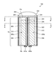
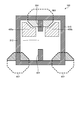
- FIGS. 2 and 3 are explanatory views showing a part of a cross section of the image pickup device 100 according to the present embodiment. Specifically, the image pickup device 100 is cut at different positions along the thickness direction of the semiconductor substrate 10. Corresponds to the cross section.
- the image sensor 100 includes an on-chip lens 200, a color filter 202, a light-shielding portion (light-shielding film) 204, and a semiconductor substrate 10 as in the comparative example. , And transfer gates 400a and 400b.
- the semiconductor substrate 10 has a pair of pixels 300a and 300b each having a photoelectric conversion unit 302.
- the semiconductor substrate 10 has a protruding portion (an example of a first separating portion) 304 that separates the pair of pixels 300a and 300b, and has an element separation wall 310 that surrounds the pixels 300a and 300b, and the protruding portion 304 and the element.
- FIG. 2 corresponds to a cross section in which the image sensor 100 is cut at a position where the above-mentioned protrusion 304 is cut
- FIG. 3 shows the space between the protrusions 304 facing each other (see slit 312 and FIG. 4).
- the image sensor 100 is provided above the light receiving surface 10a of the semiconductor substrate 10 and has one on-chip lens 200 that collects the incident light on the photoelectric conversion unit 302.
- the image sensor 100 has a structure in which a pair of pixels 300a and 300b are provided for one on-chip lens 200. That is, the on-chip lens 200 is shared by the two pixels 300a and 300b.
- the on-chip lens 200 may be formed of, for example, a silicon nitride film (SiN) or a resin-based material such as a styrene resin, an acrylic resin, a styrene-acrylic copolymer resin, or a siloxane resin. can.
- the color filter 202 is either a color filter that transmits a red wavelength component, a color filter that transmits a green wavelength component, or a color filter that transmits a blue wavelength component.
- the color filter 202 can be formed from a material in which a pigment or dye is dispersed in a transparent binder such as silicone.
- a light-shielding portion 204 is provided on the light-receiving surface 10a of the semiconductor substrate 10 so as to surround the color filter 202.
- the light-shielding portion 204 can be formed of, for example, a metal material containing tungsten (W), aluminum (Al), copper (Cu), titanium (Ti), molybdenum (Mo), nickel (Ni), or the like.
- the photoelectric conversion unit 302 having the impurities of the first conductive type (for example, N type) in the semiconductor substrate 10 of the second conductive type (for example, P type) is adjacent to each of the pixels 300a and 300b. It is provided in. As described above, the photoelectric conversion unit 302 absorbs light L having a red wavelength component, a green wavelength component, or a blue wavelength component incident through the color filter 202 to charge an electric charge. Generate. Then, in the present embodiment, the photoelectric conversion unit 302 of the pixel 300a and the photoelectric conversion unit 302 of the pixel 300b can function as a pair of phase difference detection pixels at the time of phase difference detection. That is, in the present embodiment, the phase difference can be detected by detecting the difference in the pixel signal based on the electric charge generated by the photoelectric conversion unit 302 of the pixel 300a and the photoelectric conversion unit 302 of the pixel 300b.
- the phase difference can be detected by detecting the difference in the pixel signal based on the electric charge generated by the photoelectric
- the photoelectric conversion unit 302 changes the amount of charge generated, that is, the sensitivity, depending on the incident angle of light with respect to its own optical axis (axis perpendicular to the light receiving surface). For example, the photoelectric conversion unit 302 has the highest sensitivity when the incident angle is 0 degrees, and the sensitivity of the photoelectric conversion unit 302 is the target axis when the incident angle is 0 degrees with respect to the incident angle. It has a line-symmetrical relationship. Therefore, in the photoelectric conversion unit 302 of the pixel 300a and the photoelectric conversion unit 302 of the pixel 300b, light from the same point is incident at different angles of incidence, and an amount of electric charge corresponding to the angle of incidence is generated.
- phase difference can be detected by detecting the difference in the pixel signal based on the amount of electric charge generated by the photoelectric conversion unit 302 of the pixel 300a and the photoelectric conversion unit 302 of the pixel 300b. Therefore, such a difference in pixel signals (phase difference) is detected as a difference signal by, for example, a detection unit (not shown) of the output circuit unit 24, and the defocus amount is calculated based on the detected phase difference. Autofocus can be achieved by adjusting (moving) the imaging lens (not shown).
- the phase difference is detected as the difference between the pixel signals of the photoelectric conversion unit 302 of the pixel 300a and the photoelectric conversion unit 302 of the pixel 300b, but the present embodiment is limited to this.
- the phase difference may be detected as the ratio of the pixel signals of the photoelectric conversion unit 302 of the pixel 300a and the photoelectric conversion unit 302 of the pixel 300b.
- the protruding portion 304 serves as a penetrating DTI (Deep Research Isolation) in a groove portion (trench) (not shown) provided so as to penetrate the semiconductor substrate 10 along the thickness direction of the semiconductor substrate 10 and in the trench. It is made of an embedded material composed of an oxide film (SiO), a silicon nitride film, an amorphous silicon, a polycrystalline silicon, a titanium oxide film (TiO), an oxide film such as aluminum or tungsten, or a metal film.
- DTI Deep Research Isolation
- Trench not shown
- It is made of an embedded material composed of an oxide film (SiO), a silicon nitride film, an amorphous silicon, a polycrystalline silicon, a titanium oxide film (TiO), an oxide film such as aluminum or tungsten, or a metal film.
- the accuracy of the phase difference detection deteriorates.
- the protruding portion 304 penetrates the semiconductor substrate 10
- the pair of pixels 300a and 300b can be effectively physically separated, and as a result, the occurrence of color mixing is suppressed and the phase difference is achieved.
- the accuracy of detection can be further improved.
- a slit 312 (see FIG. 4) corresponding to the space between the two protrusions 304 is provided near the center of the image sensor 100.
- the region of the slit 312 (an example of a region located around the protrusion 304 and extending in the thickness direction of the semiconductor substrate 10) is subjected to conformal doping via the protrusion 304.
- Second conductive type (for example, P type) impurities are diffused to form a diffusion region 306 (an example of the first diffusion region) (details, as will be described later, the diffusion region 306 is a device separation. It is also formed around the wall 310).
- the pair of pixels 300a and 300b can be electrically separated to prevent color mixing.
- the depth in the semiconductor substrate 10 is deepened by the conformal doping via the protruding portion 304 (here, the depth is the semiconductor substrate 10).
- a diffusion region 306 can be formed on the back surface 10a and the front surface 10b of the semiconductor substrate 10 along the thickness direction). Therefore, in the present embodiment, since the desired diffusion region 306 can be formed with high accuracy, the pair of pixels 300a and 300b can be effectively electrically separated, and as a result, the occurrence of color mixing is suppressed. , The accuracy of phase difference detection can be further improved. The details of the region of the slit 312 will be described later.
- a first conductive type (for example, N type) impurity is implanted below the diffusion region 306 provided in the slit 312 (on the surface 10b side) by ion implantation.
- a diffusion region 320 is formed.
- the diffusion region 320 is formed by ion-implanting the first conductive type impurity into the lower region in the diffusion region 306 described above so as to make a hole in the diffusion region 306. Then, the diffusion region 320 functions as an overflow path capable of exchanging the electric charges generated between the pixels 300a and 300b.
- a gate (not shown) may be provided on the surface 10b of the semiconductor substrate 10 between the transfer gates 400a and 400b.
- the pair of pixels 300a and 300b are electrically separated at the time of phase difference detection, and an overflow path is formed in the region on the surface 10b side of the slit 312 at the time of normal imaging. Channels may be formed.
- the semiconductor substrate 10 is provided with an element separation wall 310 that surrounds the pixels 300a and 300b and physically separates the adjacent image pickup elements 100.
- the element separation wall 310 includes a groove (trench) (not shown) provided so as to penetrate the semiconductor substrate 10 along the thickness direction of the semiconductor substrate 10, and a silicon oxide film and silicon embedded in the trench. It is made of a material composed of an oxide film such as a nitride film, amorphous silicon, polycrystalline silicon, a titanium oxide film, aluminum or tungsten, or a metal film. That is, the protrusion 304 and the element separation wall 310 may be formed of the same material.
- the element separation wall 310 and the projecting portion 304 have the same configuration, they can have an integrated form, and therefore can be formed at the same time.
- the protruding portion 304 can be formed at the same time as the element separation wall 310, so that the increase in the process process of the image pickup device 100 can be suppressed.
- the electric charges generated by the photoelectric conversion unit 302 of the pixel 300a and the photoelectric conversion unit 302 of the pixel 300b are provided on the surface 10b located on the side opposite to the light receiving surface 10a of the semiconductor substrate 10.
- the transfer transistor (one of the pixel transistors described above) is transferred via the transfer gates 400a and 400b.
- the transfer gates 400a and 400b can be formed from, for example, a metal film.
- the charge is accumulated in, for example, a floating diffusion portion (charge storage portion) (not shown) provided in a semiconductor region having a first conductive type (for example, N type) provided in the semiconductor substrate 10. May be good.
- the floating diffusion portion is not limited to being provided in the semiconductor substrate 10, and is provided, for example, on another substrate (not shown) laminated on the semiconductor substrate 10. It may have been.
- a plurality of pixel transistors (not shown) other than the transfer transistor described above, which are used for reading the electric charge as a pixel signal or the like, may be provided.
- the pixel transistor may be provided on the semiconductor substrate 10 or may be provided on another substrate (not shown) laminated on the semiconductor substrate 10.
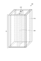
- FIG. 4 is an explanatory view showing a plane of the image sensor 100 according to the present embodiment, and more specifically, corresponds to a cross section of the image sensor 100 cut along the AA'line shown in FIG.
- the pixels 300a and 300b adjacent to each other are separated by a protruding portion 304 formed integrally with the element separation wall 310.
- the element separation wall 310 projects toward the center O of the image sensor 100 along the row direction, and two projecting portions (first) facing each other. (Example) of the separation part) 304.
- the region between the two protrusions 304 located near the center of the image sensor 100 is referred to as a slit 312.
- impurities of the second conductive type are diffused through the protrusion 304 by conformal doping, and diffused so as to surround the protrusion 304.
- Region 306 is formed.
- the pair of pixels 300a and 300b can be electrically separated to prevent color mixing.
- the second conductive type impurities are diffused through the element separation wall 310, and the diffusion region 306 is formed along the element separation wall 310.
- the two projecting portions 304 are provided at the center of the image pickup element 100 in the row direction when the image pickup element 100 is viewed from above the light receiving surface 10a, and the projecting lengths (lengths in the column direction) are mutually different. It is almost the same. Then, as described above, the two protrusions 304 are provided so as to penetrate the semiconductor substrate 10.
- the width of the protruding portion 304 is not particularly limited as long as the pair of pixels 300a and 300b can be separated.
- the projecting portion 304 and the element separation wall 310 according to the present embodiment described so far have a form as shown in FIG. 5, which is a transmission perspective view of the image pickup device 100 according to the present embodiment. That is, the protrusion 304 and the element separation wall 310 according to the present embodiment are provided so as to penetrate the semiconductor substrate 10. Further, a slit 312 is provided near the center of the image pickup device 100 between the two protrusions 304.
- the slit 312 is located near the center O of the image sensor 100, the scattering of light by the protruding portion 304 is suppressed. Therefore, according to the present embodiment, the light incident on the center O of the image sensor 100 can be incident on the photoelectric conversion unit 302 without being scattered. As a result, according to the present embodiment, the image sensor 100 can more reliably capture the light incident on the center O of the image sensor 100, so that deterioration of the image sensor can be avoided.
- the first conductive type impurities are introduced by ion implantation, and a channel serving as an overflow path is provided. Can be formed. Therefore, according to the present embodiment, the pair of pixels 300a and 300b can be separated at the time of phase difference detection, and an overflow path can be formed at the time of normal shooting. Therefore, the accuracy of the phase difference detection can be improved and the captured image can be captured. Deterioration can be avoided.
- the present embodiment since impurities can be introduced into the region of the slit 312 through the protrusion 304 by conformal doping to form the diffusion region 306, it is possible to avoid using ion implantation. .. Therefore, according to the present embodiment, since ion implantation is not used, it is possible to avoid the introduction of impurities into the photoelectric conversion unit 302, and it is possible to avoid shrinkage and damage of the photoelectric conversion unit 302. Furthermore, by using conformal doping, it is possible to repair crystal defects while applying a high temperature to uniformly diffuse impurities. As a result, according to the present embodiment, it is possible to suppress a decrease in the sensitivity of the image sensor 100 and a reduction in the dynamic range.
- the element separation wall 310 projects toward the center O of the image sensor 100 along the row direction, and two protrusions facing each other. It may have a part (an example of a first separation part) 304. Further, in this case, the two projecting portions 304 may be provided at the center of the image pickup element 100 in the row direction when the image pickup element 100 is viewed from above the light receiving surface 10a.
- the diffusion region 306 that electrically separates the pair of pixels 300a and 300b from the protruding portion 304 that physically separates the pair of pixels 300a and 300b, and the pair of pixels 300a and 300b. Since the diffusion region 320 and the like for electrically separating the two are provided, it is possible to improve the accuracy of phase difference detection and avoid deterioration of the captured image. Specifically, in the present embodiment, the pair of pixels 300a and 300b can be effectively separated by the protrusion 304 and the diffusion region 306, and as a result, the occurrence of color mixing is suppressed and the accuracy of phase difference detection is suppressed. Can be further improved.
- the overflow path is provided, when the charge of one of the pixels 300a and 300b is about to be saturated during normal imaging, the overflow path is used. By transferring the charge to the other pixel, saturation of one pixel can be avoided. Therefore, according to the present embodiment, by providing such an overflow path, the linearity of the pixel signal output from the image pickup device 100 can be ensured, and deterioration of the captured image can be prevented.
- the present embodiment since impurities can be diffused into the region of the slit 312 through the protrusion 304 by conformal doping to form the diffusion region 306, it is possible to avoid using ion implantation. .. Therefore, according to the present embodiment, since ion implantation is not used, it is possible to avoid the introduction of impurities into the photoelectric conversion unit 302, and it is possible to avoid shrinkage and damage of the photoelectric conversion unit 302. Furthermore, by using conformal doping, it is possible to repair crystal defects while applying a high temperature to uniformly diffuse impurities. As a result, according to the present embodiment, it is possible to suppress a decrease in the sensitivity of the image sensor 100 and a reduction in the dynamic range.
- the diffusion region 306 can be formed in a deep region in the semiconductor substrate 10 by conformal doping through the protruding portion 304. Therefore, in the present embodiment, since the desired diffusion region 306 can be formed with high accuracy, the pair of pixels 300a and 300b can be effectively electrically separated, and as a result, the occurrence of color mixing is suppressed. , The accuracy of phase difference detection can be further improved. Further, according to the present embodiment, since the element separation wall 310 and the projecting portion 304 have the same form, the projecting portion 304 can be formed at the same time as the element separation wall 310, which is a process step of the image pickup device 100. The increase can be suppressed.
- the slit 312 is provided in the center O of the image sensor 100, the scattering of light by the protruding portion 304 is suppressed, and the light incident on the center O of the image sensor 100 is scattered. It can be incident on the photoelectric conversion unit 302 without any problem.
- the image sensor 100 can more reliably capture the light incident on the center O of the image sensor 100, so that deterioration of the image sensor can be avoided.
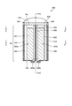
- FIG. 6 is an explanatory diagram showing a configuration example of the light-shielding portion 204 according to the present embodiment
- FIG. 7 is an explanatory diagram showing a configuration example of the light-shielding portion 204 according to a modified example of the present embodiment.
- the figure shown in the lower row corresponds to the cross section of the image sensor 100 cut along the line AA'shown in FIG. 3, and the figure shown in the upper row is BB shown in FIG. Corresponds to the cross section of the image sensor 100 cut along the'line.
- the light-shielding portion (light-shielding film) 204 is placed on the element separation wall 310 on the element separation wall 310. It may be provided along the line.
- the light-shielding portion (light-shielding film) 204 is placed on the element separation wall 310. Not only may it be provided along the element separation wall 310, but it may also be provided along the protrusion 304 on the protrusion 304 (an example of the first separation portion).
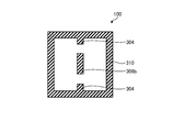
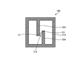
- FIG. 8 is an explanatory view showing a plane of the image sensor 100 according to the present embodiment, and more specifically, corresponds to a cross section of the image sensor 100 cut along the AA'line shown in FIG.
- the element separation wall 310 is in the row direction toward the center O (not shown) of the image sensor 100. It has two protrusions (an example of a first separation) 304 that project along and face each other. Further, the protruding lengths of the two protruding portions 304 are different from each other.
- the two projecting portions 304 may project along the row direction toward the center O (not shown) of the image sensor 100.
- the protrusions 304 are not limited to being provided in two so as to face each other, and for example, one may be provided.
- a second conductive type for example, P type
- P type the conductive type impurity
- the two protrusions 304 are not limited to being provided at the center of the image pickup device 100 in the row direction when the image pickup device 100 is viewed from above the light receiving surface 10a. , In the row direction, it may be provided at a position deviated from the center of the image sensor 100 by a predetermined distance. Therefore, a third embodiment of the present disclosure will be described in which the two protrusions 304 are provided at positions deviated from the center of the image pickup device 100 by a predetermined distance in the row direction with reference to FIG. 9.
- FIG. 9 is an explanatory view showing a plane of the image sensor 100 according to the present embodiment, and more specifically, corresponds to a cross section of the image sensor 100 cut along the AA'line shown in FIG.
- the element separation walls 310 face each other when the image sensor 100 is viewed from above the light receiving surface 10a, and are oriented along the row direction. It has two projecting portions (an example of a first separating portion) 304. Further, in the present embodiment, these projecting portions 304 are provided at positions deviated from the center of the image pickup device 100 by a predetermined distance in the row direction. In the present embodiment, the predetermined distance is not particularly limited.
- the two protrusions 304 are not limited to the form shown in FIG. 9, for example, the two protrusions protruding along the row direction (of the first separation portion).
- Example In the case of 304, it may be provided at a position deviated from the center of the image sensor 100 by a predetermined distance in the row direction.
- the present embodiment may be combined with the second embodiment described above, and therefore the protruding lengths of the two protrusions 304 may be different from each other.
- the element separation walls 310 face each other when the image pickup device 100 is viewed from above the light receiving surface 10a, and face each other in the row direction. It has two protrusions (an example of a first separation) 304 protruding along. Further, in the present embodiment, a plurality of rectangular additional walls 308 are arranged in a dot shape between the protrusions 304 (slit 312). The additional wall 308 is provided so as to penetrate the semiconductor substrate 10 in the same manner as the protrusion 304. In addition, although not shown in FIG. 10, a second conductive type (for example, P type) impurity is introduced around the additional wall 308 by conformal doping through the additional wall 308. The formed diffusion region 306 is provided.
- P type for example, P type
- a plurality of additional walls 308 are provided between the two protrusions 304 (slit 312), and a diffusion region 306 is also provided around the additional walls 308 to sufficiently provide a pair of pixels 300a and 300b. It is possible to secure more separation. Further, in the present embodiment, by providing the additional wall 308 in a dot shape, the scattering of light by the additional wall 308 is suppressed, and the light incident on the center O (not shown) of the image sensor 100 is scattered. It can be incident on the photoelectric conversion unit 302 without any light. As a result, according to the present embodiment, the image sensor 100 can more reliably capture the light incident on the center O of the image sensor 100, so that deterioration of the image sensor can be avoided.
- the cross section of the additional wall 308 is not limited to the rectangular shape as shown in FIG. 10, and the number of the additional walls 308 is also 2 as shown in FIG. The number is not limited to one, and may be one or three or more.
- one additional wall 308a is arranged between the two protrusions 304 (slit 312), and the additional wall 308a may be used as the back surface DTI. ..
- the back surface DTI forms a trench that penetrates halfway through the semiconductor substrate 10 from the light receiving surface 10a (back surface) side of the semiconductor substrate 10 along the thickness direction of the semiconductor substrate 10, and an oxide film or the like is embedded in the trench. Is formed by.
- a channel serving as the overflow path is formed.
- the cross section of the additional wall 308a is not limited to the rectangular shape as shown in FIG. 11, and the number of the additional walls 308a is also 2 as shown in FIG. The number is not limited to one, and may be one or three or more.
- a second conductivity is provided by ion implantation between the two protrusions 304 (slit 312).
- a diffusion region 306a (an example of a first diffusion region) formed by introducing a mold (for example, P-type) impurity may be provided.
- the protruding portion 304 may be formed of a material different from that of the element separation wall 310.
- FIG. 13 is an explanatory view showing a plane of the image sensor 100 according to the present embodiment, and more specifically, corresponds to a cross section of the image sensor 100 cut along the AA'line shown in FIG.
- the projecting portion 304 and the element separation wall 310 are made of a material made of an oxide film such as a silicon oxide film, a silicon nitride film, an amorphous silicon, polycrystalline silicon, a titanium oxide film, aluminum, tungsten, or a metal film. Consists of. Therefore, in the present embodiment, as shown in FIG. 13, the material selected from the above-mentioned materials, and the protrusion 304 and the element separation wall 310 may be formed from different materials.
- the element separation wall 310 is formed of a silicon oxide film
- the protruding portion 304 is formed of a titanium oxide film having a high refractive index, which has a small difference in refractive index from the silicon forming the semiconductor substrate 10.
- the scattering of light by the protruding portion 304 is suppressed, and the light incident on the center O (not shown) of the image sensor 100 can be incident on the photoelectric conversion unit 302 without being scattered.
- the image sensor 100 can more reliably capture the light incident on the center O of the image sensor 100, so that deterioration of the image sensor can be avoided.
- the protrusion 304 is not limited to being formed of a titanium oxide film, and for example, another material may be used as long as the material has a small difference in refractive index from the material forming the semiconductor substrate 10. There may be.
- FIG. 14 is an explanatory view showing a plane of the image sensor 100 according to the present embodiment, and more specifically, corresponds to a cross section of the image sensor 100 cut along the AA'line shown in FIG.
- the element separation walls 310 project toward the center of the image sensor 100 along the row direction and mutually.
- the four protrusions 304 and 324 are provided so as to penetrate the semiconductor substrate 10.
- a diffusion region 306 an example of a first diffusion region and an example of a second diffusion region.
- a first conductive type for example, N type
- a diffusion region 320 that functions as an overflow path is formed.
- the inside of the image sensor 100 is separated into four pixels 300a, 300b, 300c, and 300d by such four protrusions 304.
- one image sensor 100 can detect the phase difference in both the row direction and the column direction.
- the present invention is not limited to the four protrusions 304 and 324, and four or more protrusions may be provided (for example, eight).
- FIG. 15 is an explanatory view showing a plane of the image sensor 100 according to the present embodiment, and more specifically, corresponds to a cross section of the image sensor 100 cut along the AA'line shown in FIG.
- a pixel separation wall (an example of a separation portion) 334 composed of a back surface DTI is provided between the pair of pixels 300a and 300b.
- the back surface DTI forms a trench that penetrates from the light receiving surface 10a (back surface) side of the semiconductor substrate 10 to the middle of the semiconductor substrate 10 along the thickness direction of the semiconductor substrate 10 and is inside the trench. It is formed by embedding an oxide film or the like in the.
- the region on the surface 10b side of the pixel separation wall 334, which is not penetrated by the pixel separation wall 334 is the overflow path.
- an overflow path may be formed by introducing a first conductive type impurity into the region by ion implantation.
- the pixel separation wall 334 may or may not be in contact with the element separation wall 310, and is not particularly limited. If they are not in contact with each other, a second conductive type (for example, P type) impurity is formed by conformal doping via the element separation wall 310 or ion implantation between the pixel separation wall 334 and the element separation wall 310. Is formed by introducing the above, and a diffusion region (not shown) that electrically separates the pair of pixels 300a and 300b is provided.
- the pair of pixels 300a and 300b are effective by providing the pixel separation wall 334 composed of the back surface DTI that physically separates the pair of pixels 300a and 300b at the time of phase difference detection.
- the occurrence of color mixing can be suppressed and the accuracy of phase difference detection can be further improved.
- the charge of one of the pixels 300a and 300b is likely to be saturated during normal imaging due to the overflow path located in the region on the surface 10b side of the pixel separation wall 334, By transferring the charge to the other pixel through the overflow path, saturation of one pixel can be avoided.
- the linearity of the pixel signal output from the image pickup device 100 can be ensured and the deterioration of the captured image can be prevented.
- a pixel separation wall 334 formed by introducing a second conductive type (for example, P type) impurity by ion implantation is provided between the pair of pixels 300a and 300b. May be done. Even in such a modification, the pixel separation wall 334 formed by ion implantation extends from the light receiving surface 10a (back surface) side of the semiconductor substrate 10 to the middle of the semiconductor substrate 10 along the thickness direction of the semiconductor substrate 10. It is formed in a penetrating form. In the modification, the region on the surface 10b side of the pixel separation wall 334, which is not penetrated by the pixel separation wall 334, is the overflow path in the thickness direction of the semiconductor substrate 10.
- a second conductive type for example, P type
- the overflow path may be formed by preventing impurities from being implanted into the region on the surface 10b side of the pixel separation wall 334 at the time of ion implantation for forming the pixel separation wall 334. It may be formed by introducing a first conductive type impurity into the region by ion implantation. In this modification as well, the pixel separation wall 334 may or may not be in contact with the element separation wall 310, and is not particularly limited.
- the pair of pixels 300a and 300b can be effectively electrically separated, and as a result, the pair of pixels 300a and 300b can be effectively electrically separated. It is possible to suppress the occurrence of color mixing and further improve the accuracy of phase difference detection. Further, in the present embodiment, when the charge of one of the pixels 300a and 300b is likely to be saturated during normal imaging due to the overflow path located in the region on the surface 10b side of the pixel separation wall 334, By transferring the charge to the other pixel through the overflow path, saturation of one pixel can be avoided. By providing such an overflow path, the linearity of the pixel signal output from the image pickup device 100 can be ensured, and deterioration of the captured image can be prevented.
- FIG. 16 is an explanatory diagram showing a configuration example of the light-shielding portion 204 according to the present embodiment.
- the figure shown in the lower row corresponds to a cross section obtained by cutting the image sensor 100 along the line AA'shown in FIG. 3, and the figure shown in the upper row is the line BB'shown in FIG. Corresponds to the cross section of the image sensor 100 cut.
- the light-shielding portion (light-shielding film) 204 is placed on the element separation wall 310. It may have two projecting portions 206 that are provided along the element separation wall 310 and project toward the center O of the image sensor 100 along the row direction and face each other. Alternatively, in the present embodiment and the modified example, the light-shielding portion 204 may be provided along the element separation wall 310 and may not have the protruding portion 206.
- FIG. 17 is an explanatory view showing a part of a cross section of the image pickup device 100 according to the present embodiment, and more specifically, corresponds to a cross section of the image pickup device 100 cut along the thickness direction of the semiconductor substrate 10.
- FIG. 18 is an explanatory view showing a plane of the image sensor 100 according to the present embodiment, and more specifically, corresponds to a cross section of the image sensor 100 cut along the CC'line shown in FIG. FIG.
- FIG. 19 is an explanatory view showing a plane of the image sensor 100 according to the present embodiment, and more specifically, corresponds to a cross section of the image sensor 100 cut along the DD'line shown in FIG.
- FIG. 20 is an explanatory view showing a part of a cross section of the image pickup device 100 according to the present embodiment, and more specifically, corresponds to a cross section obtained by cutting the semiconductor substrate 10 along the line EE shown in FIG.
- FIG. 21 is an explanatory view showing a part of a cross section of the image sensor 100 for each color according to the present embodiment, and more specifically, corresponds to a cross section obtained by cutting the semiconductor substrate 10 along the thickness direction of the semiconductor substrate 10. ..
- one additional wall 308b is arranged between the two protrusions 304 (slit 312), and the additional wall 308b is designated as a surface DTI. ..
- the surface DTI forms a trench extending from the surface 10b side, which is the opposite surface of the light receiving surface 10a of the semiconductor substrate 10, to the middle of the semiconductor substrate 10 along the thickness direction of the semiconductor substrate 10. It is formed by embedding an oxide film or the like in the trench. By adjusting the depth of the trench, it is possible to adjust the length of the semiconductor substrate 10 in the thickness direction of the additional wall 308b.
- a channel serving as the overflow path may be formed by introducing impurities into the region on the back surface 10a side of the additional wall 308b, which is not penetrated by the additional wall 308b.
- the additional wall 308b extends from the surface 10b, which is the surface opposite to the light receiving surface 10a of the semiconductor substrate 10, to the middle of the semiconductor substrate 10 along the thickness direction of the semiconductor substrate 10 (the substrate thickness direction). Provided. As a result, the length of the additional wall 308b in the substrate thickness direction becomes shorter than the length of the two protrusions 304 in the substrate thickness direction. Therefore, since the end surface (the surface on the light receiving surface 10a side) of the additional wall 308b is separated from the light receiving surface 10a, scattering of incident light by the additional wall 308b in the vicinity of the light receiving surface 10a can be suppressed.
- the volume of the additional wall 308b can be reduced on the light receiving surface 10a side, and the incident light can be reliably scattered in the vicinity of the light receiving surface 10a by the additional wall 308b. Can be suppressed.
- incident light may be scattered by two protrusions 304 arranged near the center of the image sensor 100 on the light receiving surface 10a, which may cause deterioration of color mixing.
- the suppression of sensitivity decrease may be insufficient.
- the additional wall 308b disappears near the center of the image sensor 100 on the light receiving surface 10a side, and incident light scattering can be suppressed. As a result, it is possible to suppress color mixing, a decrease in sensitivity, a decrease in the amount of saturated charge, and the like.
- the additional wall 308b is formed according to the wavelength of the incident light in each of the RGB (Red, Green, Blue) image pickup elements 100, that is, the photoelectric conversion depth.
- the trench depth for this purpose may be adjusted.
- the trench depth is set to be shallow.
- the trench depth is set deep.
- the trench depth is set between the trench depth of the R pixel and the trench depth of the B pixel.
- the trench depth that is, the length of the additional wall 308a in the substrate thickness direction may be determined according to the wavelength of the incident light incident on the light receiving surface 10a. This makes it possible to minimize the scattering of incident light for each color. As a result, it is possible to suppress incident light scattering according to the wavelength of the incident light, so that it is possible to reliably suppress color mixing, a decrease in sensitivity, a decrease in the amount of saturated charge, and the like.
- FIG. 22 is an explanatory view showing a plane of the image sensor 100 according to the present embodiment. Specifically, FIG. 22 is a cross section obtained by cutting the image sensor 100 along a plane direction (a direction orthogonal to the thickness direction of the semiconductor substrate 10). handle.
- FIG. 23 is an explanatory view showing a part of a cross section of the image sensor 100 for each color according to the present embodiment, and more specifically, corresponds to a cross section obtained by cutting the semiconductor substrate 10 along the thickness direction of the semiconductor substrate 10. .. FIG.
- FIG. 24 is an explanatory view showing a plane of the image sensor 100 according to the present embodiment, and more specifically, corresponds to a cross section of the image sensor 100 cut along the plane direction.
- FIG. 25 is an explanatory view showing a part of a cross section of the image sensor 100 for each color according to the present embodiment, and more specifically, corresponds to a cross section obtained by cutting the semiconductor substrate 10 along the thickness direction of the semiconductor substrate 10. ..
- the width of the central portion of the additional wall 308b (for example, the length in the row direction) is the width of both ends of the additional wall 308b (for example, the length in the row direction). For example, it may be narrower than the length in the row direction).
- the length of the central portion of the additional wall 308b in the substrate thickness direction may be shorter than the length of both end portions of the additional wall 308b in the substrate thickness direction.
- the line width of the central portion of the additional wall 308b is reduced with respect to both ends, and the depth of the trench for forming the central portion of the additional wall 308b is made shallower in the substrate thickness direction of the central portion of the additional wall 308b.
- the width of the central portion of the additional wall 308b is narrower than that of both ends of the additional wall 308b, and the length of the central portion of the semiconductor substrate 10 in the thickness direction is the both ends of the additional wall 308b.
- the present invention is not limited to this, and either the width or the length thereof may be reduced. Further, the width of the additional wall 308b may be shorter than the width of the two protrusions 304.
- the individual widths (for example, the lengths in the row direction) of the two protrusions 304 are the widths of the additional wall 308b (for example, the length in the row direction). For example, it may be narrower than the length in the row direction).
- the two protrusions 304 may be provided so as to extend from the surface 10b of the semiconductor substrate 10 to the middle of the semiconductor substrate 10 along the thickness direction of the semiconductor substrate 10. At this time, the length of the additional wall 308b in the substrate thickness direction may be shorter than the length of the two protrusions 304 in the individual substrate thickness direction.
- the line widths of the two protrusions 304 are narrowed, and the depth of the trench for forming the two protrusions 304 is made shallow.
- the volume of the two protrusions 304 can be reduced in addition to the volume of the wall 308b, scattering of incident light by the additional wall 308b and the two protrusions 304 in the vicinity of the light receiving surface 10a can be reliably suppressed.
- the individual widths of the two protrusions 304 are narrower than, but not limited to, the width of the additional wall 308b, and are not limited to, for example, one of the two protrusions 304.
- the width may be narrower than the width of the additional wall 308b.
- FIG. 26 is a process cross-sectional view for explaining a part of the manufacturing process of the image pickup device 100 according to the present embodiment. Specifically, FIG. 26 is a cross-sectional view obtained by cutting the semiconductor substrate 10 along the thickness direction of the semiconductor substrate 10. handle.
- a mask M1 such as a photomask is formed on the surface 10b of the semiconductor substrate 10 (see the first figure from the left in FIG. 26).
- the mask M1 is formed, for example, by laminating a photoresist layer on the surface 10b of the semiconductor substrate 10 by a spin coating method or the like, and patterning the photoresist layer in accordance with a trench forming pattern.
- a mask M2 that functions as a protective layer is formed on the mask M1, and a part of the trench T1 for forming the element separation wall 310 is formed by etching such as dry etching (second from the left in FIG. 26). reference). After that, the mask M2 is removed (see the third figure from the left in FIG.
- etching is performed to form a trench T1 for forming the element separation wall 310 and a trench T2 for forming the additional wall 308b.
- a material such as an oxide film is embedded in the trench T1 and the trench T2 to form the element separation wall 310 and the additional wall 308b.
- the mask M1 is also removed, and the image sensor 100 having the final structure is formed through a post-process.
- the effect related to the other embodiment can be obtained. That is, it is possible to avoid deterioration of the captured image while improving the accuracy of phase difference detection. Further, since the end surface of the additional wall 308b (the surface on the light receiving surface 10a side) is separated from the light receiving surface 10a and the volume of the additional wall 308b can be reduced on the light receiving surface 10a side, the additional wall 308b or the protrusion Scattering of incident light near the light receiving surface 10a by the unit 304 can be suppressed.
- FIG. 27 is an explanatory view showing a plane of the image sensor 100 according to the present embodiment, and more specifically, corresponds to a cross section of the image sensor 100 cut along the plane direction.
- FIG. 27 is an explanatory view showing a plane of the image sensor 100 according to the present embodiment, and more specifically, corresponds to a cross section of the image sensor 100 cut along the plane direction.
- FIG. 28 is an explanatory view showing a part of a cross section of the image pickup device 100 according to the present embodiment, and more specifically, corresponds to a cross section obtained by cutting the semiconductor substrate 10 along the thickness direction of the semiconductor substrate 10.
- FIG. 29 is an explanatory view showing a part of a cross section of the image sensor 100 of the comparative example according to the present embodiment, and more specifically, corresponds to a cross section obtained by cutting the semiconductor substrate 10 along the thickness direction of the semiconductor substrate 10. ..
- the diffusion region 306b is formed in a shape that expands from the front surface 10b of the semiconductor substrate 10 toward the inside of the semiconductor substrate 10 and narrows from the inside of the semiconductor substrate 10 toward the back surface 10a of the semiconductor substrate 10. That is, the diffusion region 306b has a first region R1 extending from the front surface 10b of the semiconductor substrate 10 toward the inside of the semiconductor substrate 10 and a second region R1 narrowing from the inside of the semiconductor substrate 10 toward the back surface 10a of the semiconductor substrate 10. It has a region R2. These first region R1 and second region R2 are connected.
- the central axis of the first region R1 and the central axis of the second region R2 are positioned so as not to deviate from each other, but the present invention is not limited to this, and for example, left and right. It may be positioned so as to deviate in the direction (for example, the row direction). This also applies to the configurations shown in FIGS. 30 to 35 below.
- the diffusion region 306b is formed in a shape that expands from the front surface 10b of the semiconductor substrate 10 toward the inside of the semiconductor substrate 10 and narrows from the inside of the semiconductor substrate 10 toward the back surface 10a of the semiconductor substrate 10.
- the diffusion region 306b is narrower than the diffusion region 306a (see FIG. 29), so that the photoelectric conversion region can be widened.
- the diffusion region 306b can be deformed as follows. Therefore, the detailed configuration of the diffusion region 306b will be described with reference to FIGS. 30 to 35.
- 30 to 35 are explanatory views showing a part of a cross section of the image sensor 100 according to the present embodiment, and more specifically, correspond to a cross section obtained by cutting the semiconductor substrate 10 along the thickness direction of the semiconductor substrate 10. ..
- the diffusion region 306b may be formed so that the first region R1 and the second region R2 are separated from each other without being connected. Even in the diffusion region 306b having such a shape, it is possible to suppress the spread of the diffusion region 306b, and the photoelectric conversion region can be widened.
- the first region R1 and the second region R2 are compared with the first region R1 and the second region R2 shown in FIG. 28. It may be formed so as to be thin. The first region R1 and the second region R2 are connected. In the diffusion region 306b having such a shape, it is possible to further suppress the spread of the diffusion region 306b as compared with the first region R1 and the second region R2 shown in FIG. 28, and the photoelectric conversion region is surely widened. be able to.
- the impurity concentrations in the first region R1 and the second region R2 are the first region R1 and the second region shown in FIG. 28. It may be formed so as to be darker than R2.
- the first region R1 and the second region R2 are connected. According to such a diffusion region 306b, potential adjustment (potential design) can be easily performed by changing the impurity concentrations in the first region R1 and the second region R2.
- the diffusion region 306b has a length (depth) in the substrate thickness direction of the first region R1 as a length (depth) in the substrate thickness direction of the second region R2. It may be formed to be longer than the depth).
- the first region R1 and the second region R2 are connected. According to such a diffusion region 306b, potential adjustment (potential design) can be easily performed by changing the lengths of the first region R1 and the second region R2 in the thickness direction of each substrate.
- the diffusion region 306b may be formed so that the lengths of the first region R1 and the second region R2 in the thickness direction of the individual substrates are different.
- the substrate of the second region R2 may be formed in the opposite manner to the above. It may be formed so that the length in the thickness direction is longer than the length in the substrate thickness direction of the first region R1.
- the diffusion region 306b may be formed so that the first region R1 is thinner than the second region R2. That is, the length in the direction orthogonal to the substrate thickness direction in the first region R1 is shorter than the length in the direction orthogonal to the substrate thickness direction in the first region R1.
- the first region R1 and the second region R2 are connected. According to such a diffusion region 306b, potential adjustment (potential design) can be easily performed by changing the individual thicknesses of the first region R1 and the second region R2.
- the diffusion region 306b may be formed so that the individual thicknesses of the first region R1 and the second region R2 are different.
- the second region R2 is the first region R1 as described above. It may be formed to be thinner.
- the diffusion region 306b may be formed so that the impurity concentration in the first region R1 is lower than the impurity concentration in the second region R2.
- the first region R1 and the second region R2 are connected.
- potential adjustment potential design
- the diffusion region 306b may be formed so that the individual impurity concentrations of the first region R1 and the second region R2 are different.
- the impurity concentration of the second region R2 is the first. It may be formed so as to be thinner than the impurity concentration in the region R1 of.
- Ion implantation is performed to form the diffusion regions 306b having various shapes as shown in FIGS. 28, 30 to 35.
- various conditions such as power, implantation time, processing temperature, and electric field are adjusted. By appropriately adjusting these various conditions, it is possible to obtain diffusion regions 306b having various shapes as shown in FIGS. 28, 30 to 35.
- one additional wall 308 may be provided between the two protrusions 304 (slit 312).
- a diffusion region 306b is provided between each of the two protrusions 304 and one additional wall 308 (two regions).
- the cross section of the image sensor 100 cut along the GG'line shown in FIG. 36 is the same as the cross section shown by FIG. 28, and the cross section of the image sensor 100 cut along the HH'line shown in FIG. 36 is the same as the cross section shown in FIG. It is the same as the cross section shown in FIG. 34.
- a potential gradient see the white arrow in FIG. 36
- the electric charge can be easily rolled (moved) toward the transfer gates 400a and 400b. That is, potential adjustment (potential design) such as forming a potential gradient can be easily performed by combining various shapes of the first region R1 and the second region R2 constituting the diffusion region 306b, a combination of impurity concentrations, and the like. be able to.
- FIGS. 37 and 38 are process cross-sectional views for explaining a part of the manufacturing process of the image pickup apparatus 1 according to the present embodiment. Note that, in FIGS. 37 and 38, for the sake of clarity, only the main parts of the imaging apparatus 1 related to the present embodiment are shown, and the other parts are not shown.
- a photodiode, a floating diffusion (all not shown), transfer gates 400a and 400b, an element separation wall 310, a protrusion 304, and the like are formed.
- Ion implantation is performed on the semiconductor substrate 10 of the above.
- ion implantation is performed from the surface 10b of the first semiconductor substrate 10.
- the first semiconductor substrate 10 and the second semiconductor substrate 11 are joined via the interlayer insulating film 10A.
- CMP Chemical Mechanical Polishing
- a grinder, or the like is used for the first semiconductor substrate 10, and thinning is performed from the back surface 10a of the first semiconductor substrate 10 as shown in the middle of FIG.
- ion implantation is executed again into the first semiconductor substrate 10.
- ion implantation is performed from the back surface 10a of the first semiconductor substrate 10.
- the support substrate 12 is bonded to the first semiconductor substrate 10, and for example, activation annealing is executed.
- various transistors, signal lines (for example, pixel drive wiring 26, horizontal signal line 28, etc.) and the like are formed on the second semiconductor substrate 11.
- the logic substrate 13 is joined to the second semiconductor substrate 11.
- the logic board 13 has a plurality of circuits such as various circuit units 21 to 25, for example.
- a CMP, a grinder, or the like is used for the support substrate 12, and the wall thickness is reduced as shown in the lower part of FIG. 38.
- the effect related to the other embodiment can be obtained. That is, it is possible to avoid deterioration of the captured image while improving the accuracy of phase difference detection.
- the diffusion region 306b is formed in a shape that extends from the front surface 10b of the semiconductor substrate 10 toward the inside of the semiconductor substrate 10 and narrows from the inside of the semiconductor substrate 10 toward the back surface 10a of the semiconductor substrate 10. As a result, the diffusion region 306b (see FIG. 28) is narrower than the diffusion region 306a (see FIG. 29), so that the photoelectric conversion region can be widened.
- the protruding portion 304 may be composed of the extending portion 304a and the protruding portion 304b.
- FIG. 39 is an explanatory view showing a plane of the image sensor 100 according to the present embodiment, and more specifically, corresponds to a cross section of the image sensor 100 cut along the plane direction.
- FIG. 40 is an explanatory view showing a part of a cross section of the image pickup device 100 according to the present embodiment, and more specifically, corresponds to a cross section obtained by cutting the semiconductor substrate 10 along the I-I'line shown in FIG. 39.
- FIG. 41 is an explanatory view showing a part of a cross section of the image pickup device 100 according to the comparative example of the present embodiment, and more specifically, corresponds to a cross section obtained by cutting the semiconductor substrate 10 along the thickness direction of the semiconductor substrate 10. ..
- the two protrusions 304 have an extension portion 304a and a protrusion 304b, respectively.
- the extending portion 304a is connected to the element separation wall 310 and extends in the row direction from the element separation wall 310.
- the protrusion 304b is provided at the end of the extension 304a and extends in the row direction.
- the shape of the stretched portion 304a and the shape of the protruding portion 304b are rectangular, and in the example of FIG. 39, the protruding portion 304 has a T-shape.
- Each protrusion 304b has facing surfaces S1 facing each other. When viewed from above the light receiving surface 10a, the individual width of each facing surface S1 (for example, the length in the row direction) is wider than the individual line width (for example, the length in the row direction) of each extending portion 304a.
- a diffusion layer that is, a diffusion region 306 is formed only by conformal doping on the wall surface of the element separation wall 310, and the slit 312 is filled with the diffusion region 306. Be done. This is because the two protrusions 304 forming the slit 312 are formed straight so as to be orthogonal to the light receiving surface 10a. That is, the shape of the slit 312 is not a tapered shape but a linear shape.
- the processed shape of the full trench may become a tapered shape due to the influence of the microloading effect during etching.
- the region of the slit 312 may not be completely filled by the diffusion region 306, and sufficient potential separation may not be possible.
- the etching rate can be improved in the case of forming a trench (sparse) with a wide line width as compared with the case of forming a trench (dense) with a narrow line width.
- the etching rate is increased and the shape of the slit 312 is tapered as compared with the case where the protruding portion 304 is formed only by the stretched portion 304a. It is possible to make a linear shape without. As a result, ion implantation can be omitted and an increase in the number of manufacturing steps can be suppressed. Further, since the verticality of the slit 312 (verticality of the trench) is improved, the saturation charge amount Qs can be improved as compared with the case where ion implantation is indispensable, and further, the color mixing and the quantum efficiency Qe can be improved. In addition, it is possible to reduce crystal defect damage and improve white spots.
- FIG. 42 is a graph showing the relationship between the width of the slit 312 and the width of the protrusion 304 according to the present embodiment.
- the line width (length in the row direction) of the stretched portion 304a is L1
- the width of the protrusion 304b length in the row direction
- the semiconductor substrate 10 Assuming that the width (length in the row direction) of the slit 312 on the back surface 10a side is L3 and the width (length in the row direction) of the slit 312 on the front surface 10b side of the semiconductor substrate 10 is L4, as shown in FIG.
- a graph showing the relationship between "L2 / L1 (ratio)” and “L4-L3 (difference)” is required. From this graph, by making the width L2 of the protrusion 304b 1.2 times or more the line width L1 of the stretched portion 304a, the slit 312 can be made vertical, and a sufficient effect can be obtained at a practical level. can. Further, when verticalization is required, it is desirable that the width L2 of the protrusion 304b is 1.4 times or more the line width L1 of the stretched portion 304a.
- the formation position of the slit 312 it is also possible to move the formation position of the slit 312 in the row direction. In this case, the length of the stretched portion 304a (for example, the length in the row direction) is adjusted. Such movement of the formation position of the slit 312 is also possible in the subsequent configurations of FIGS. 45 to 50.
- the transfer gates 400a and 400b and the floating diffusion region can be separated from the blooming path region for transfer and transfer. It is possible to improve the margin for white spots and the like.
- FIG. 43 is a process cross-sectional view for explaining a part of the manufacturing process of the image pickup device 100 according to the present embodiment.
- FIG. 43 is a cross-sectional view of the semiconductor substrate 10 cut along the LL'line shown in FIG. 39.
- FIG. 44 is a process cross-sectional view for explaining a part of the manufacturing process of the image pickup device 100 according to the present embodiment.
- FIG. 44 is a cross-sectional view of the semiconductor substrate 10 cut along the line I-I shown in FIG. Corresponds to.
- the mask M1 (for example, an inorganic mask such as SiO 2) is formed on the back surface 10a (or the front surface 10b) of the semiconductor substrate 10.
- the mask M2 is formed on the mask M1.
- the mask M2 is formed, for example, by laminating a photoresist layer on the mask M1 on the surface 10b of the semiconductor substrate 10 by a spin coating method or the like, and patterning the photoresist layer according to a trench forming pattern.
- the protrusion 304 and the trench for forming the element separation wall 310 are formed by etching such as dry etching, and the mask M2 is removed.
- conformal doping is performed to form the diffusion region 306.
- a material such as an oxide film is embedded in each trench to form a protruding portion 304 and an element separation wall 310.
- the mask M1 is removed, and the image sensor 100 having the final structure is formed through a post-process.
- the protruding portion 304 can be deformed as follows. Therefore, the detailed configuration of the protruding portion 304 will be described with reference to FIGS. 45 to 50.
- 45 to 50 are explanatory views showing a plane of the image sensor 100 according to the present embodiment, and more specifically, correspond to a cross section of the image sensor 100 cut along the plane direction.
- the protruding portion 304 has a stretched portion 304a and a protruding portion 304b.
- the extending portion 304a is connected to the element separation wall 310 and extends in the row direction from the element separation wall 310.
- the protrusion 304b is provided at the end of the extension 304a and extends in the row direction.
- the shape of the stretched portion 304a and the shape of the protrusion 304b are rectangular, and in the example of FIG. 45, the shape of the protrusion 304 is T-shaped.
- the protrusion 304b has a facing surface S1 facing the wall surface of the element separation wall 310.
- the width of the facing surface S1 of the protrusion 304b (for example, the length in the row direction) is longer than the line width of the extension portion 304a (for example, the length in the row direction).
- the two protrusions 304 are each bent in the middle so that the slit 312 is formed to be slanted.
- Each protrusion 304 has facing surfaces S1 facing each other.
- the individual lengths of the facing surfaces S1 eg, the length in the tilt direction
- the individual line widths of the two protrusions 304 eg, the length in the row direction.
- each protrusion 304 is formed so as to be displaced in the row direction.
- Each protrusion 304 has facing surfaces S1 facing each other.
- the individual length of each facing surface S1 (for example, the length in the column direction) is longer than the individual line width (for example, the length in the row direction) of each protrusion 304.
- the two protrusions 304 have an extension portion 304a and a protrusion 304b, respectively.
- the extending portion 304a is connected to the element separation wall 310 and extends in the row direction from the element separation wall 310.
- the protrusion 304b is provided at the end of the extension 304a, and is formed in a shape extending in the row direction and the column direction.
- the shape of the stretched portion 304a is rectangular, and in the example of FIG. 48, the shape of the protrusion 304b is L-shaped.
- Each protrusion 304 has facing surfaces S1 facing each other.
- each additional wall 308c in addition to the two protruding portions 304, two additional walls (an example of the separating portion) 308c are provided so as to face each other with the center of the image sensor 100 in between. Has been done.
- Each additional wall 308c has facing surfaces S1 facing each other. When viewed from above the light receiving surface 10a, the individual length of each facing surface S1 (for example, the length in the column direction) is longer than the individual line width (for example, the length in the row direction) of each protrusion 304.
- the two protrusions 304 have an extension portion 304a and a protrusion 304b, respectively.
- the configuration of the protrusion 304b when viewed from above the light receiving surface 10a, is the same as that of FIG. 39 except that the shape is circular.
- the shape of the protrusion 304b may be various shapes such as an elliptical shape and a trapezoidal shape in addition to the circular shape.
- the effect related to the other embodiment can be obtained. That is, it is possible to avoid deterioration of the captured image while improving the accuracy of phase difference detection.
- the width of the facing surface S1 of the protruding portion 304 (for example, the length in the row direction) is wider than the line width (for example, the length in the row direction) of the extending portion 304a of the protruding portion 304.
- the etching rate on the facing surface S1 side of the protruding portion 304 can be increased, and the shape of the slit 312 can be made into a linear shape instead of a tapered shape.
- the verticality of the slit 312 verticality of the trench
- the saturation charge amount Qs can be improved as compared with the case where ion implantation is indispensable, and further, the color mixing and the quantum efficiency Qe can be improved.
- FIG. 51 is an explanatory view showing a plane of the image sensor 100 according to the present embodiment, and more specifically, corresponds to a cross section of the image sensor 100 cut along the plane direction.
- FIG. 52 is an explanatory view showing a plane of the image sensor 100 according to the comparative example of the present embodiment, and more specifically, corresponds to a cross section of the image sensor 100 according to the comparative example cut along the plane direction.
- the two pixel separation walls 334a are arranged in a row direction so as to face each other with the center of the image sensor 100 in between.
- Each pixel separation wall 334a is separated from the element separation wall 310 without contacting the element separation wall 310, and is further separated from each other.
- the individual shape of each pixel separation wall 334a is rectangular.
- the diffusion region 306 includes a first region 306A and a second region 306B.
- the first region 306A is a region formed by a solid phase diffusion process for each trench for forming the two pixel separation barriers 334a.
- the second region 306B is a region formed by a solid phase diffusion process on the trench for forming the device separation wall 310. That is, the diffusion from the trench corresponding to the element separation wall 310 on the outer periphery and the diffusion from each trench corresponding to the two protrusions 304 occur independently, so that the diffusion region 306 becomes the first region 306A and the first region 306A. It will have 2 regions 306B.
- the boron diffusion region 306 is formed. It will be formed widely.
- the wide formation of the diffusion region 306 causes a decrease in the saturated charge amount. Therefore, as described above, by arranging the element separation wall 310 and the two pixel separation walls 334a apart from each other and forming the separation structure independently, it is possible to independently diffuse the solid phase of the separation structure.
- boron is diffused by a solid phase diffusion process (an example of a diffusion process), but the diffusion process is not limited to the solid phase diffusion process, and the diffusion process is not limited to the solid phase diffusion process. It is also possible to use a doping technique that performs doping.
- the two pixel separation walls 334a are positioned on the center line passing through the center of the image sensor 100, but the present invention is not limited to this, and for example, the left-right direction of FIG. 51 (as an example). , In the row direction). This also applies to the configurations shown in FIGS. 54 to 57 below.
- FIG. 53 is a process cross-sectional view for explaining a part of the manufacturing process of the image pickup device 100 according to the present embodiment, and more specifically, corresponds to a cross section of the image pickup device 100 cut along a plane direction.
- the individual trenches T4 for forming the two pixel separation walls 334a are formed at internal positions away from the formation position of the element separation wall 310 (from the left of FIG. 53). See the first figure).
- a solid phase diffusion process is then used for those trenches T4 to form a solid phase diffusion layer (eg P-type layer) or first region 306A around each trench T4 and then into those trenches T4.
- a material such as an oxide film is embedded to form a pixel separation wall 334a (see the second figure from the left in FIG. 53).
- a trench T5 for forming the element separation wall 310 is formed in a rectangular shape of a predetermined size surrounding each trench T4, and a solid phase diffusion process is used for the trench T5 to form a solid phase diffusion layer (for example, a P-type layer).
- a solid phase diffusion layer for example, a P-type layer.
- a second region 306B is formed around the trench T5, and finally, a material such as an oxide film is embedded in the trench T5 to form an element separation wall 310 (see the third figure from the left in FIG. 53). ).
- the diffusion region 306 including the first region 306A and the second region 306B is formed.
- the pixel separation wall 334a can be deformed as follows. Therefore, the detailed configuration of the pixel separation wall 334a will be described with reference to FIGS. 54 to 57.
- 54 to 57 are explanatory views showing a plane of the image sensor 100 according to the present embodiment, and more specifically, correspond to a cross section of the image sensor 100 cut along the plane direction.
- each pixel separation wall 334a is separated from the element separation wall 310 without contacting the element separation wall 310, and is further separated from each other.
- the individual shapes of the pixel separation walls 334a are rectangular, and the pixel separation walls 334a are arranged so as to form a cross shape.
- two pixel separation walls 334a having a plane area smaller than those pixel separation walls 334a are provided. These pixel separation walls 334a having a small area (size) are arranged in the row direction so as to face each other with the center of the image sensor 100 in between. Individual parts of the two pixel separation walls 334a are located in the region between the other two pixel separation walls 334a.
- the individual shape of each pixel separation wall 334a is rectangular.
- each pixel separation wall 334a is provided.
- the four pixel separation walls 334a are arranged in dots in the row direction passing through the center of the image sensor 100.
- Each pixel separation wall 334a is separated from the element separation wall 310 without contacting the element separation wall 310, and is further separated from each other.
- each pixel separation wall 334a when viewed from above the light receiving surface 10a, each pixel separation wall 334a has a rectangular shape, and each pixel separation wall 334a is arranged on one straight line.
- the two pixel separation walls 334a are formed in a circular shape when viewed from above the light receiving surface 10a.
- the configuration of each pixel separation wall 334a is the same as that of FIG. 51 except that the shape is circular.
- the shape of the pixel separation wall 334a may be various shapes such as an elliptical shape and a trapezoidal shape in addition to the circular shape.
- the effect related to the other embodiment can be obtained. That is, it is possible to avoid deterioration of the captured image while improving the accuracy of phase difference detection. Further, by arranging the element separation wall 310 and each pixel separation wall 334a separately and forming the separation structure independently, it becomes possible to independently perform a diffusion process such as solid phase diffusion of the separation structure. , It is possible to suppress a decrease in the amount of saturated electric charge.
- FIG. 58 is an explanatory view showing a plane of the image sensor 100 according to the present embodiment, and more specifically, corresponds to a cross section of the image sensor 100 cut along the plane direction.
- FIG. 59 is an explanatory view showing both sides and a cross section of the image sensor 100 according to the present embodiment, and the cross section corresponds to a cross section obtained by cutting the image sensor 100 along the MM'line shown in FIG. 58.
- FIG. 60 is an explanatory diagram showing the relationship between the slit width (length of the slit gap) of the image pickup device 100 according to the present embodiment, the light collection characteristic, and the pixel characteristic.
- the pair of protruding portions 304 are formed in a tapered shape in which the separation distance (slit width) from each other gradually changes in the depth direction.
- the distance between the pair of protrusions 304 from each other gradually increases in the depth direction from the front surface 10b toward the back surface (light receiving surface) 10a (from the upper surface to the lower surface in FIG. 58) (a). ⁇ B).
- the protrusion amount As a result, it is possible to secure the protrusion amount as a whole while keeping the light receiving surface 10a side of the pair of projecting portions 304 away from the center.
- FIG. 60 it is possible to reduce light scattering while maintaining the pixel characteristics, and it is possible to eliminate the trade-off between the light collection characteristics and the pixel characteristics.
- ba 2 ⁇ (t / tan ( ⁇ )).
- a is the length of the slit 312 on the front surface 10b side
- b is the length of the slit 312 on the back surface (light receiving surface) 10a side
- t is the thickness (in the depth direction) from the front surface 10b to the back surface 10a.
- Length where ⁇ is the taper angle of the slit 312 with respect to the surface 10b. Even if the taper angle ⁇ is small, there is a large difference in the slit width from the front surface 10b to the back surface 10a depending on the thickness t from the front surface 10b to the back surface 10a.
- the pair of protrusions 304 can be deformed as follows. Therefore, the detailed configuration of the pair of protrusions 304 will be described with reference to FIGS. 61 to 71.
- 61, 65, 68, and 69 are explanatory views showing both sides and a cross section of the image sensor 100 according to the present embodiment, respectively.
- 62 to 64 and 66 are explanatory views showing a cross section of the image pickup device 100 according to the present embodiment, respectively.
- 67, 70, and 71 are explanatory views showing both sides of the image pickup device 100 according to the present embodiment.
- the pair of protrusions 304 are separated from each other by a predetermined depth in the depth direction from the front surface 10b to the back surface 10a (from the upper surface to the lower surface in FIG. 61). It is substantially the same, and is formed so as to gradually widen in the depth direction from the middle in the depth direction (a ⁇ b).
- the trench shape in the condensing portion is dominant, so it is effective if the condensing portion is changed.
- the separation distance on the back surface (light receiving surface) 10a side is preferably wide because it is effective for light collection, and the separation distance on the front surface 10b side is preferably wide from the viewpoint of potential design.
- the central separation distance is effective for Qs, so it is better to be narrow.
- the pair of projecting portions 304 are separated from each other in multiple stages in the depth direction from the front surface 10b to the back surface 10a (from the upper surface to the lower surface in FIG. 63). Each is formed to change.
- the distance between the pair of protrusions 304 changes in two steps in the depth direction, and the distance on the front surface 10b side is narrower than the distance on the back surface 10a (). a ⁇ b). Therefore, each of the pair of protrusions 304 has a step.
- the separation distance of the pair of protrusions 304 may change discontinuously rather than continuously, and may change in multiple steps such as three steps or four steps instead of two steps.
- the pair of protrusions 304 are separated from each other in two steps in the depth direction from the front surface 10b to the back surface 10a (from the upper surface to the lower surface in FIG. 64). It is formed so as to gradually widen in the depth direction from the middle of the depth direction (a ⁇ c ⁇ b).
- the intermediate taper shape shown in FIGS. 61 and 62, the multi-stage processing shape shown in FIG. 63, and the like may be combined.
- one protruding portion 304 has a depth of separation distance from the element separation wall 310 from the front surface 10b to the back surface 10a (from the upper surface to the lower surface in FIG. 65). It is formed so as to gradually widen in the direction (a ⁇ b).
- one protrusion 304 changes in two steps in the depth direction from the front surface 10b to the back surface 10a (from the upper surface to the lower surface in FIG. 66). It is formed.
- the separation distance on the front surface 10b side is narrower than the separation distance on the back surface 10a side (a ⁇ b).
- the four protrusions 304 are gradually separated from each other by the pair of protrusions 304 facing each other from the front surface 10b toward the back surface 10a in the depth direction. It is formed to be wide (a ⁇ b). These protrusions 304 are arranged in a cross shape.
- the intermediate taper shape shown in FIGS. 61 and 62 and the multi-step processing shown in FIG. 63 are applied to a plurality of protruding portions 304 such as one protruding portion 304 and four protruding portions 304. Shapes and the like may be applied, or they may be applied in combination.
- one protruding portion 304 has a line width (direction orthogonal to the stretching direction) from the front surface 10b to the back surface 10a (from the upper surface to the lower surface in FIG. 69).
- the width is formed so as to gradually narrow in the depth direction (d> e).
- the distance between the protruding portion 304 and the element separation wall 310 gradually increases from the front surface 10b toward the back surface 10a along the depth direction (a ⁇ b).
- the four pixel separation walls 334a are formed so that the individual line widths gradually narrow in the depth direction from the front surface 10b to the back surface 10a. There is. These pixel separation walls 334a are arranged in dots in the row direction passing through the center of the image sensor 100. Each pixel separation wall 334a is separated from the element separation wall 310 without contacting the element separation wall 310, and is further separated from each other.
- the gap (width of the slit 312) of the slit 312 on the light receiving surface 10a side scattering by each protruding portion 304 is suppressed, and the light collecting characteristic is particularly effective in the vicinity of the light receiving surface 10a.
- FIG. 72 is a process cross-sectional view for explaining a part of the manufacturing process of the image pickup device 100 according to the present embodiment. Specifically, FIG. 72 is a cross section obtained by cutting the semiconductor substrate 10 along the thickness direction of the semiconductor substrate 10. handle.
- FFTI surface FTI: Full Trench Isolation
- the semiconductor substrate 10 and the bonded substrate 501 are bonded to each other to reduce the wall thickness.
- the thinned semiconductor substrate 10 is backfilled, and the color filter 202 and the on-chip lens 200 are laminated.
- the bonded substrate 502 for example, a logic substrate, a semiconductor substrate, or the like is used.
- FIG. 73 is an explanatory view showing a plane of the image sensor 100 according to the present embodiment, and more specifically, corresponds to a cross section of the image sensor 100 cut along the plane direction.
- FIG. 74 is an explanatory view showing a plane of the image sensor 100 according to the comparative example of the present embodiment, and more specifically, corresponds to a cross section of the image sensor 100 according to the comparative example cut along the plane direction.
- the two transfer gates 400a and 400b are positioned on one end side (for example, the upper side of FIG. 73) of the cell region surrounded by the element separation wall 310.
- the cell region is included in the image sensor 100.
- the cell area is square.
- the FD unit 601 is a floating diffusion shared by two adjacent cell areas (see the dotted line area in FIG. 73).
- the FD unit 601 is positioned on one end side (for example, the upper side of FIG. 73) of the cell region.
- the shape of the FD portion 601 is not a regular octagon but an octagon having a long side and a short side.
- the FD portion 601 is horizontally long, and in the FD portion 601 the length in the direction orthogonal to the extending direction of the protruding portion 304 is longer than the length in the extending direction of the protruding portion 304.
- the FD unit 601 for example, Poly—Si (polycrystalline Si) is used.
- the ground portion 602 is a ground portion shared by two adjacent cell areas (see the dotted line area in FIG. 73).
- the ground portion 602 is positioned on one end side (for example, the lower side of FIG. 73) of the cell region.
- the shape of the ground portion 602 is not a regular octagon but an octagon having a long side and a short side.
- the ground portion 602 is horizontally long, and in the ground portion 602, the length in the direction orthogonal to the extending direction of the protruding portion 304 is longer than the length in the extending direction of the protruding portion 304.
- As the ground portion 602 for example, Poly—Si (polycrystalline Si) is used.
- the ground portion 602 is a ground (GND) potential and functions as, for example, a well contact.
- the width g of the slit 312 (the length in the vertical direction of FIG. 74) is the slit shown in FIG. 75. It is narrower than the width f of 312 (the length in the vertical direction in FIG. 75).
- the region (divided portion) of the slit 312 comes closer to the FD portion 601 (for example, N + diffusion layer) and the ground portion 602 (for example, P + diffusion layer). Therefore, the FD portion 601 and the ground portion 602 may interfere with the region of the slit 312, resulting in an increase in variation in single pixel Qs, deterioration of FD white spots, and the like.
- the shapes of the FD portion 601 and the ground portion 602 are each horizontally long.
- the length of the protruding portion 304 in the extending direction is shorter than the length in the direction orthogonal to the extending direction of the protruding portion 304.
- the FD portion 601 and the ground portion 602 are separated from the region (divided portion) of the slit 312 as compared with FIG. 74.
- the shapes of the transfer gates 400a and 400b for example, the shape of the transfer gates 400a and 400b on the slit 312 side can be enlarged to improve the transfer (improve the transfer characteristics) and suppress the variation of the potential barrier. be able to.
- the ground portion 602 can be deformed as follows. Therefore, the detailed configuration of the ground portion 602 will be described with reference to FIGS. 75 to 78.
- 75 to 78 are explanatory views showing a plane of the image sensor 100 according to the present embodiment, and in detail, correspond to a cross section of the image sensor 100 cut along the plane direction.
- ground portions 602 are provided at two corners of the cell region. These ground portions 602 are ground portions shared by four adjacent cell regions. In the example of FIG. 75, it is provided at the lower left and lower right of the four corners of the cell area. Each ground portion 602 is deviated from the FD portion 601 by half the cell pitch (length in the left-right direction in FIG. 75) of the cell region. As a result, each ground portion 602 is farther away from the region of the slit 312 than in FIGS. 73 and 74. Therefore, it is possible to reliably suppress an increase in single-pixel Qs variation and deterioration of FD white spots.
- the ground portion 602 shown in FIG. 75 is provided so as to be rotated by 90 degrees (other configurations are the same as those in FIG. 75). As a result, each ground portion 602 is farther away from the region of the slit 312 than in FIG. 75. Therefore, it is possible to more reliably suppress an increase in single-pixel Qs variation and deterioration of FD white spots.
- the ground portion 602 shown in FIG. 75 is formed in a regular octagon shape (other configurations are the same as those in FIG. 75). Even in this case, each ground portion 602 is separated from the region of the slit 312 as compared with FIG. 74. Therefore, it is possible to reliably suppress an increase in single-pixel Qs variation and deterioration of FD white spots.
- the FD portion 601 shown in FIG. 77 is formed in a regular octagonal shape, and the shapes of the transfer gates 400a and 400b are the same as those in FIG. 74 (other configurations). Is the same as in FIG. 77). Even in this case, each ground portion 602 is separated from the region of the slit 312 as compared with FIG. 74. Therefore, it is possible to reliably suppress an increase in single-pixel Qs variation and deterioration of FD white spots.
- the shapes of the FD portion 601 and the ground portion 602 may be the same (see FIGS. 73 to 76 and 78) or may be different (see FIG. 77). Further, the shape of the FD portion 601 or the ground portion 602 may be a shape having a long side and a short side, for example, a shape symmetrical in the vertical and horizontal directions (see FIGS. 73 to 78), or a shape asymmetrical in the vertical and horizontal directions. It may be.
- the FD unit 601 and the ground unit 602 are arranged in an array (for example, in a matrix along the row direction and the column direction), but may be arranged at the same pitch as the cell pitch of the cell region, or half of each other. They may be arranged with the pitch shifted.
- the shape of the FD portion 601 and the ground portion 602 may be, for example, another polygonal shape or an elliptical shape in addition to the octagonal shape having the long side and the short side.
- the image pickup device 100 in which the first conductive type is N-type, the second conductive type is P-type, and electrons are used as signal charges has been described.
- the embodiment is not limited to such an example.
- this embodiment can be applied to an image pickup device 100 in which the first conductive type is P-type, the second conductive type is N-type, and holes are used as signal charges.
- the semiconductor substrate 10 does not necessarily have to be a silicon substrate, and may be another substrate (for example, an SOI (Silicon On Insulator) substrate, a SiGe substrate, or the like). Further, the semiconductor substrate 10 may have a semiconductor structure or the like formed on such various substrates.
- SOI Silicon On Insulator
- the image pickup device 1 is not limited to the image pickup device 1 that detects the distribution of the incident light amount of visible light and captures the image as an image.
- the present embodiment includes an imaging device that captures the distribution of incident amounts of infrared rays, X-rays, particles, etc. as an image, and fingerprints that detect the distribution of other physical quantities such as pressure and capacitance and capture the image as an image. It can be applied to an image pickup device (physical quantity distribution detection device) such as a detection sensor.
- the image pickup apparatus 1 according to the embodiment of the present disclosure can be manufactured by using the methods, devices, and conditions used for manufacturing a general semiconductor device. That is, the image pickup apparatus 1 according to the present embodiment can be manufactured by using the manufacturing process of the existing semiconductor device.
- Examples of the above-mentioned method include a PVD (Physical Vapor Deposition) method, a CVD (Chemical Vapor Deposition) method, and an ALD (Atomic Layer Deposition) method.
- the PVD method includes a vacuum vapor deposition method, an EB (electron beam) vapor deposition method, various sputtering methods (magnetron sputtering method, RF (Radio Frequency) -DC (Direct Curent) combined bias sputtering method, and ECR (Electron Cyclotron Resonance) sputtering method.
- examples of the CVD method include a plasma CVD method, a thermal CVD method, an organometallic (MO) CVD method, and an optical CVD method.
- Various printing methods such as method and flexo printing method; stamp method; spray method; air doctor coater method, blade coater method, rod coater method, knife coater method, squeeze coater method, reverse roll coater method, transfer roll coater method, gravure coater method.
- Kiss coater method, cast coater method, spray coater method, slit orifice coater method, calendar coater method and various other coating methods can be mentioned.
- examples of the patterning method include chemical etching such as shadow mask, laser transfer, and photolithography, and physical etching by ultraviolet rays, laser, and the like.
- examples of the flattening technique include a CMP (Chemical Mechanical Polishing) method, a laser flattening method, and a reflow method.
- the protrusion an example of the separation part 304,324, the additional wall (an example of the separation part) 308, 308a, 308b, 308c, and the pixel separation wall (an example of the separation part) 334.
- the structure of 334a has been described, the structure according to the embodiment of the present disclosure is not limited thereto.
- various aspects of the structure of each part will be described in detail with reference to FIGS. 79 to 84.
- FIG. 79 is an explanatory view showing a plane of the image sensor 100 according to the present embodiment (modification example), and more specifically, corresponds to a cross section of the image sensor 100 cut along the plane direction.
- FIG. 80 is an explanatory view showing a part of a cross section of the image sensor 100 for each structure, that is, the semiconductor substrate 10 for each structure according to the present embodiment (modification example), and in detail, FIG. It corresponds to the cross section obtained by cutting the semiconductor substrate 10 for each structure with a ′ line.
- the pixel separation wall 334 has a structure of any one of RDTI (back surface DTI), FDTI (front surface DTI), FFTI (front surface FTI: Full Trench Isolation), RFTI (back surface FTI), and RDTI + FDTI. Is formed in.
- the trench T3 is formed in the thickness direction of the semiconductor substrate 10. A material such as an oxide film is embedded in the trench T3.
- the trench T3 is formed in a tapered shape extending inward from the surface of the semiconductor substrate 10, but the trench T3 is not limited to this.
- the trench T3 may be formed straight so as to be orthogonal (or substantially orthogonal) to the surface of the semiconductor substrate 10.
- the RDTI has a structure in which the trench T3 is formed from the back surface 10a (light receiving surface 10a) of the semiconductor substrate 10 to the middle of the semiconductor substrate 10.
- the FDTI has a structure in which a trench is formed from the surface 10b of the semiconductor substrate 10 (the surface opposite to the light receiving surface 10a) to the middle of the semiconductor substrate 10.
- the FFTI has a structure formed by penetrating the trench T3 from the front surface 10b to the back surface 10a of the semiconductor substrate 10.
- RFTI is a method of forming the semiconductor substrate 10 by penetrating the trench T3 from the back surface 10a to the front surface 10b.
- RDTI + FDTI is a method in which the above-mentioned RDTI and FDTI are combined. In this RDTI + FDTI, the trench T3 extending from the back surface 10a and the trench T3 extending from the front surface 10b are connected near the center in the thickness direction of the semiconductor substrate 10.
- FIG. 81 is an explanatory view showing a plane of the image sensor 100 according to the present embodiment (modification example), and more specifically, corresponds to a cross section of the image sensor 100 cut along the plane direction.
- FIG. 82 is an explanatory view showing a part of a cross section of the image sensor 100 for each structure, that is, the semiconductor substrate 10 for each structure according to the present embodiment (modification example). It corresponds to the cross section obtained by cutting the semiconductor substrate 10 for each structure with a ′ line.
- the protruding portion 304 is formed in any one of RDTI, FDTI, FFTI, RFTI, and RDTI + FDTI structure, similarly to the pixel separation wall 334 described above (see FIG. 80).
- the trench T3 is formed in the thickness direction of the semiconductor substrate 10.
- the trench T3 is formed so that the protruding portion 304 comes into contact with the element separation wall 310 and does not separate from each other.
- a material such as an oxide film is embedded in the trench T3.
- the trench T3 is formed in a tapered shape extending inward from the surface of the semiconductor substrate 10, but the trench T3 is not limited to this.
- the trench T3 may be formed straight so as to be orthogonal (or substantially orthogonal) to the surface of the semiconductor substrate 10.
- the pixel separation wall 334 as shown in FIG. 79, another structure may be used in addition to one pixel separation wall 334 that is not in contact with the element separation wall 310.
- a plurality of pixel separation walls 334 may be formed in a row in a dot shape so as to be non-contact with the element separation wall 310.
- the number of pixel separation walls 334 is 6, but the number is not limited.
- the pixel separation wall 334 may be formed so that both ends thereof come into contact with the element separation wall 310.
- the pixel separation wall 334 is formed in the column direction, but the present invention is not limited to this, and the pixel separation wall 334 may be formed in the row direction, for example.
- the second protrusion 324 and the pixel separation wall 334a and the additional walls 308, 308a, 308b, 308c according to each of the above embodiments have the above-mentioned RDTI and FDTI.
- FFTI, RFTI, RDTI + FDTI structures can be applied.
- the embodiment of the present disclosure may be applied to other structures such as structures.
- the embodiments of the present disclosure may be applied to a two-layer laminated CIS, a three-layer laminated CIS, a two-stage pixel CIS, and the like.
- the application to the two-stage pixel CIS is an example, and the application to the one-stage pixel is also possible.
- the structures of the two-layer laminated CIS, the three-layer laminated CIS, and the two-stage pixel CIS will be described in detail with reference to FIGS. 85 to 87.
- FIG. 85 shows an example of a two-layer laminated structure to which the embodiment of the present disclosure can be applied.
- FIG. 85 is an explanatory view showing a cross section of a two-layer laminated structure to which the image pickup apparatus 1 according to the embodiment of the present disclosure can be applied.
- the image pickup apparatus 1 has a pixel region (pixel array unit 20) and a control circuit on the side of the first semiconductor substrate 31 by means of one through-connection conductor 84 formed on the first semiconductor substrate 31.
- the unit 25 and a logic circuit (not shown) on the side of the second semiconductor substrate 45 are electrically connected to each other. That is, in the example of FIG. 85, the first semiconductor substrate 31 and the second semiconductor substrate 45 are laminated, and these semiconductor substrates 31 and 45 are electrically connected by the through connecting conductor 84.
- the wiring 53 of the uppermost layer of the second semiconductor substrate 45 is reached from the back surface 31b side of the first semiconductor substrate through the first semiconductor substrate 31, and the uppermost layer of the first semiconductor substrate 31.
- a through connection hole 85 that reaches the wiring 40 of the above is formed.
- the through connection conductor 84 connecting the wiring 40 on the pixel region and the control circuit section 25 side and the wiring 53 on the logic circuit side in the through connection hole 85. Embed.
- the wiring 40 of each layer is connected to each other so that the wiring 40 of the uppermost layer to be connected becomes the connection end.
- a photodiode (PD) serving as a photoelectric conversion part of each pixel is formed in the semiconductor well region 32 of the first semiconductor substrate 31. Further, a source / drain region 33 of each pixel transistor is formed in the semiconductor well region 32.
- the semiconductor well region 32 is formed by introducing, for example, a p-type impurity, and the source / drain region 33 is formed by introducing, for example, an n-type impurity.
- the photodiode (PD) and the source / drain region 33 of each pixel transistor are formed by ion implantation from the substrate surface.
- the photodiode (PD) has an n-type semiconductor region 34 and a p-type semiconductor region 35 on the surface side of the substrate.
- a gate electrode 36 is formed on the surface of a substrate constituting a pixel via a gate insulating film, and pixel transistors Tr1 and Tr2 are formed by a source / drain region 33 paired with the gate electrode 36.
- the pixel transistor Tr1 adjacent to the photodiode (PD) corresponds to a transfer transistor, and its source / drain region corresponds to floating diffusion (FD).
- FD floating diffusion
- Each unit pixel is separated by the element separation region 38.
- MOS transistors Tr3 and Tr4 constituting the control circuit are formed on the first semiconductor substrate 31.
- the MOS transistors Tr3 and Tr4 are formed by an n-type source / drain region 33 and a gate electrode 36 formed via a gate insulating film.
- a first layer interlayer insulating film 39 is formed on the surface of the first semiconductor substrate 31, and a connecting conductor 44 connected to a required transistor is formed in the interlayer insulating film 39.
- a multilayer wiring layer 41 is formed by a plurality of layers of wiring 40 via an interlayer insulating film 39 so as to connect to each connecting conductor 44.
- a plurality of MOS transistors forming a logic circuit separated by the element separation region 50 are formed in the p-type semiconductor well region 46 on the surface side of the second semiconductor substrate 45.
- Each of the MOS transistors Tr6, Tr7, and Tr8 has a pair of n-type source / drain regions 47 and a gate electrode 48 formed via a gate insulating film.
- a first layer interlayer insulating film 49 is formed on the surface of the second semiconductor substrate 45, and a connecting conductor 54 for connecting to a required transistor is formed in the interlayer insulating film 49.
- a connecting conductor 51 that penetrates from the surface of the interlayer insulating film 49 to a desired depth in the second semiconductor substrate 45 is provided.
- an insulating film 52 for insulating the connecting conductor 51 and the semiconductor substrate 45 is provided.
- the multilayer wiring layer 55 is formed by providing the wiring 53 having a plurality of layers in the interlayer insulating film 49 so as to connect to each connecting conductor 54 and the connecting conductor 51 for taking out the electrodes.
- the first semiconductor substrate 31 and the second semiconductor substrate 45 are bonded so that the multilayer wiring layers 41 and 55 face each other.
- red (R), green (G), and blue (B) on-chip color filters 74 are provided on the flattening film 73 corresponding to each pixel, and on the flattening film 73, for example, red (R), green (G), and blue (B) on-chip color filters 74 are provided.
- An on-chip microlens 75 is provided.
- an opening 77 corresponding to the connecting conductor 51 is provided, and a spherical electrode bump 78 electrically connected to the connecting conductor 51 through the opening 77 is provided.
- FIG. 86 shows an example of a three-layer laminated structure to which the embodiment of the present disclosure can be applied.
- FIG. 86 is an explanatory view showing a cross section of a three-layer laminated structure to which the image pickup apparatus 1 according to the embodiment of the present disclosure can be applied.
- the image pickup apparatus 1 has a three-layer laminated structure in which the first semiconductor substrate 211, the second semiconductor substrate 212, and the third semiconductor substrate 213 are laminated.
- a memory circuit is formed in addition to the first semiconductor substrate 211 on which the sensor circuit is formed and the second semiconductor substrate 212 on which the logic circuit is formed. It is composed of a third semiconductor substrate 213.
- the logic circuit and the memory circuit are configured to operate with input / output of signals to and from the outside.
- a photodiode (PD) 234 serving as a pixel photoelectric conversion unit is formed on the first semiconductor substrate 211, and a source / drain region of each pixel transistor is formed in the semiconductor well region. NS. Further, a gate electrode is formed on the surface of the first semiconductor substrate 211 via a gate insulating film, and a pixel transistor Tr1 and a pixel transistor Tr2 are provided by a source / drain region paired with the gate electrode. Specifically, the pixel transistor Tr1 adjacent to the photodiode (PD) 234 corresponds to the transfer transistor, and its source / drain region corresponds to floating diffusion (FD). Further, the first semiconductor substrate 211 is provided with an interlayer insulating film (not shown), and a connecting conductor 244 connected to the pixel transistors Tr1 and Tr2 is provided in the interlayer insulating film.
- the first semiconductor substrate 211 is provided with a contact 265 used for electrical connection with the second semiconductor substrate 212.
- the contact 265 is connected to the contact 311 of the second semiconductor substrate 212, which will be described later, and is also connected to the pad 280a of the first semiconductor substrate 211.
- a logic circuit is formed on the second semiconductor substrate 212. Specifically, a MOS transistor Tr6, a MOS transistor Tr7, and a MOS transistor Tr8, which are a plurality of transistors constituting a logic circuit, are formed in a p-type semiconductor well region (not shown) of the second semiconductor substrate 212. There is. Further, in the second semiconductor substrate 212, a connecting conductor 254 connected to the MOS transistor Tr6, the MOS transistor Tr7, and the MOS transistor Tr8 is formed.
- the second semiconductor substrate 212 is formed with a contact 311 used for electrical connection with the first semiconductor substrate 211 and the third semiconductor substrate 213.
- the contact 311 is connected to the contact 265 of the first semiconductor substrate 211 and also to the pad 330a of the third semiconductor substrate 213.
- a memory circuit is formed on the third semiconductor substrate 213. Specifically, a MOS transistor Tr11, a MOS transistor Tr12, and a MOS transistor Tr13, which are a plurality of transistors constituting the memory circuit, are formed in the p-type semiconductor well region (not shown) of the third semiconductor substrate 213. There is.
- a MOS transistor Tr11 a MOS transistor Tr12, and a connection conductor 344 connected to the MOS transistor Tr13 are formed.
- FIG. 87 shows an example of a two-stage pixel structure to which the embodiment of the present disclosure can be applied.
- FIG. 87 is an explanatory view showing a cross section of a two-stage pixel structure to which the image pickup apparatus 1 according to the embodiment of the present disclosure can be applied.
- the first substrate 80 is configured by laminating an insulating layer 86 on a semiconductor substrate 11.
- the first substrate 80 has an insulating layer 86 as a part of the interlayer insulating film 87.
- the insulating layer 86 is provided in the gap between the semiconductor substrate 11 and the semiconductor substrate 21A described later.
- the first substrate 80 has a photodiode PD (83), a transfer transistor TR, and a floating diffusion FD.
- the first substrate 80 has a configuration in which a transfer transistor TR and a floating diffusion FD are provided on a portion of the semiconductor substrate 11 on the surface side (the side opposite to the light incident surface side, the second substrate 20A side).
- the transfer transistor TR has a planar transfer gate TG.
- the transfer gate TG is not limited to such a configuration, and may be a vertical transfer gate penetrating the well layer 42.
- the second substrate 20A is configured by laminating an insulating layer 88 on the semiconductor substrate 21A.
- the second substrate 20A has an insulating layer 88 as a part of the interlayer insulating film 87.
- the insulating layer 88 is provided in the gap between the semiconductor substrate 21A and the semiconductor substrate 81.
- the second substrate 20A has a read-out circuit 22A.
- the second substrate 20A has a configuration in which the readout circuit 22A is provided on the surface side (third substrate 30 side) of the semiconductor substrate 21A.
- the second substrate 20A is attached to the first substrate 80 with the back surface of the semiconductor substrate 21A facing the front surface side of the semiconductor substrate 11. That is, the second substrate 20A is attached to the first substrate 80 face-to-back.
- the second substrate 20A further has an insulating layer 89 penetrating the semiconductor substrate 21A in the same layer as the semiconductor substrate 21A.
- the second substrate 20A has an insulating layer 89 as a part of the interlayer insulating
- the laminate composed of the first substrate 80 and the second substrate 20A has an interlayer insulating film 87 and a through wiring 90 provided in the interlayer insulating film 87. Specifically, the through wiring 90 is electrically connected to the floating diffusion FD and the connection wiring 91 described later.
- the second substrate 20A further has, for example, a wiring layer 56 on the insulating layer 88.
- the wiring layer 56 further has, for example, a plurality of pad electrodes 58 in the insulating layer 57.
- Each pad electrode 58 is made of, for example, a metal such as Cu (copper) or Al (aluminum).
- Each pad electrode 58 is exposed on the surface of the wiring layer 56.
- Each pad electrode 58 is used for electrical connection between the second substrate 20A and the third substrate 30 and for bonding the second substrate 20A and the third substrate 30.
- the third substrate 30 is configured by, for example, laminating an interlayer insulating film 61 on a semiconductor substrate 81. As will be described later, the third substrate 30 is attached to the second substrate 20A with the surfaces on the front side facing each other.
- the third substrate 30 has a configuration in which a logic circuit 82 is provided on a portion of the semiconductor substrate 81 on the surface side.
- the third substrate 30 further has, for example, a wiring layer 62 on the interlayer insulating film 61.
- the wiring layer 62 has, for example, an insulating layer 92 and a plurality of pad electrodes 64 provided in the insulating layer 92.
- the plurality of pad electrodes 64 are electrically connected to the logic circuit 82.
- Each pad electrode 64 is made of, for example, Cu (copper).
- Each pad electrode 64 is exposed on the surface of the wiring layer 62.
- Each pad electrode 64 is used for electrical connection between the second substrate 20A and the third substrate 30 and for bonding the second substrate 20A and the third
- transistors other than the transfer gates 400a and 400b for example, CMOS transistors
- the floating diffusion FD is provided at a position adjacent to the transfer gates 400a and 400b.
- the pixel transistor regions Ra and Rb are formed so as to sandwich the pixel region Rc including the pixels 300a and 300b.
- the selection transistor SEL and the amplification transistor AMP are arranged in the pixel transistor area Ra on the left side in FIG.
- the reset transistor RST is arranged in the pixel transistor area Rb on the right side in FIG. 88.
- the pixel sharing method, transistor arrangement, photodiode embedded structure, and the like according to FIG. 88 are merely examples, and are not limited thereto.
- the image pickup elements 100 shown in FIG. 88 are arranged as shown in FIG. 89 (repeated arrangement), and the selection transistor SEL, the amplification transistor AMP, and the reset transistor RST are arranged in the individual pixel transistor regions Ra and Rb of each image pickup element 100.
- the FD transfer transistors FDG may be arranged one by one.
- the FD transfer transistor FDG is used when switching the conversion efficiency.
- the arrangement of each transistor may be uniform or uneven with respect to each pixel transistor region Ra and Rb.
- a plurality of amplification transistors AMP may be arranged with respect to the four image pickup devices 100, and these amplification transistor AMPs may be arranged in parallel.
- FIG. 90 is an explanatory diagram showing an example of a schematic functional configuration of the camera 700 to which the technique according to the present disclosure (the present technique) can be applied.
- the camera 700 includes an image pickup device 702, an optical lens 710, a shutter mechanism 712, a drive circuit unit 714, and a signal processing circuit unit 716.
- the optical lens 710 forms an image of image light (incident light) from the subject on the image pickup surface of the image pickup apparatus 702.
- the signal charge is accumulated in the image pickup device 100 of the image pickup apparatus 702 for a certain period of time.
- the shutter mechanism 712 controls the light irradiation period and the light blocking period of the image pickup apparatus 702 by opening and closing.
- the drive circuit unit 714 supplies drive signals for controlling the signal transfer operation of the image pickup apparatus 702, the shutter operation of the shutter mechanism 712, and the like.
- the image pickup apparatus 702 performs signal transfer based on the drive signal (timing signal) supplied from the drive circuit unit 714.
- the signal processing circuit unit 716 performs various signal processing. For example, the signal processing circuit unit 716 outputs the signal-processed video signal to a storage medium (not shown) such as a memory, or outputs it to a display unit (not shown).
- FIG. 91 is a block diagram showing an example of a schematic functional configuration of a smartphone 900 to which the technology according to the present disclosure (the present technology) can be applied.
- the smartphone 900 includes a CPU (Central Processing Unit) 901, a ROM (Read Only Memory) 902, and a RAM (Random Access Memory) 903.
- the smartphone 900 also includes a storage device 904, a communication module 905, and a sensor module 907.
- the smartphone 900 includes an image pickup device 909, a display device 910, a speaker 911, a microphone 912, an input device 913, and a bus 914.
- the smartphone 900 may have a processing circuit such as a DSP (Digital Signal Processor) in place of or in combination with the CPU 901.
- DSP Digital Signal Processor
- the CPU 901 functions as an arithmetic processing device and a control device, and controls all or a part of the operation in the smartphone 900 according to various programs recorded in the ROM 902, the RAM 903, the storage device 904, and the like.
- the ROM 902 stores programs, calculation parameters, and the like used by the CPU 901.
- the RAM 903 primarily stores a program used in the execution of the CPU 901, parameters that change appropriately in the execution, and the like.
- the CPU 901, ROM 902, and RAM 903 are connected to each other by a bus 914.
- the storage device 904 is a data storage device configured as an example of the storage unit of the smartphone 900.
- the storage device 904 is composed of, for example, a magnetic storage device such as an HDD (Hard Disk Drive), a semiconductor storage device, an optical storage device, and the like.
- the storage device 904 stores programs executed by the CPU 901, various data, various data acquired from the outside, and the like.
- the communication module 905 is a communication interface composed of, for example, a communication device for connecting to the communication network 906.
- the communication module 905 may be, for example, a communication card for a wired or wireless LAN (Local Area Network), Bluetooth (registered trademark), WUSB (Wireless USB), or the like. Further, the communication module 905 may be a router for optical communication, a router for ADSL (Asymmetric Digital Subscriber Line), a modem for various communications, or the like.
- the communication module 905 transmits and receives signals and the like to and from the Internet and other communication devices using a predetermined protocol such as TCP (Transmission Control Protocol) / IP (Internet Protocol).
- the communication network 906 connected to the communication module 905 is a network connected by wire or wirelessly, and is, for example, the Internet, a home LAN, infrared communication, satellite communication, or the like.
- the sensor module 907 is, for example, a motion sensor (for example, an acceleration sensor, a gyro sensor, a geomagnetic sensor, etc.), a biometric information sensor (for example, a pulse sensor, a blood pressure sensor, a fingerprint sensor, etc.), or a position sensor (for example, GNSS (Global Navigation)). Includes various sensors such as Satellite System) receiver, etc.).
- a motion sensor for example, an acceleration sensor, a gyro sensor, a geomagnetic sensor, etc.
- a biometric information sensor for example, a pulse sensor, a blood pressure sensor, a fingerprint sensor, etc.
- GNSS Global Navigation
- Includes various sensors such as Satellite System) receiver, etc. etc.
- the image pickup device 909 is provided on the surface of the smartphone 900 and can image an object or the like located on the back side or the front side of the smartphone 900. Specifically, the image pickup device 909 is applied to an image pickup element (not shown) such as a CMOS (Complementary MOS) image sensor to which the technique (the present technology) according to the present disclosure can be applied, and a signal photoelectrically converted by the image pickup device. It can be configured to include a signal processing circuit (not shown) that performs image pickup signal processing. Further, the image pickup apparatus 909 further includes an optical system mechanism (not shown) composed of an image pickup lens, a zoom lens, a focus lens, and the like, and a drive system mechanism (not shown) that controls the operation of the optical system mechanism.
- an image pickup element such as a CMOS (Complementary MOS) image sensor to which the technique (the present technology) according to the present disclosure can be applied
- CMOS Complementary MOS
- the image pickup apparatus 909 further includes an optical system mechanism
- the image sensor collects the incident light from the object as an optical image
- the signal processing circuit photoelectrically converts the imaged optical image on a pixel-by-pixel basis and reads out the signal of each pixel as an image pickup signal.
- the captured image can be acquired by image processing.
- the display device 910 is provided on the surface of the smartphone 900, and can be, for example, a display device such as an LCD (Liquid Crystal Display) or an organic EL (Electroluminescence) display.
- the display device 910 can display an operation screen, an image captured by the image pickup device 909 described above, and the like.
- the speaker 911 can output, for example, call voice, voice associated with the video content displayed by the display device 910 described above, and the like to the user.
- the microphone 912 can collect, for example, the voice of the user's call, the voice including the command to activate the function of the smartphone 900, and the voice of the surrounding environment of the smartphone 900.
- the input device 913 is a device operated by the user, such as a button, a keyboard, a touch panel, and a mouse.
- the input device 913 includes an input control circuit that generates an input signal based on the information input by the user and outputs the input signal to the CPU 901.
- the user can input various data to the smartphone 900 and instruct the processing operation.
- the configuration example of the smartphone 900 is shown above.
- Each of the above-mentioned components may be configured by using general-purpose members, or may be configured by hardware specialized for the function of each component. Such a configuration can be appropriately changed depending on the technical level at the time of implementation.
- FIG. 92 is a diagram showing an example of a schematic configuration of an endoscopic surgery system to which the technique according to the present disclosure (the present technique) can be applied.
- FIG. 92 shows a surgeon (doctor) 11131 performing surgery on patient 11132 on patient bed 11133 using the endoscopic surgery system 11000.
- the endoscopic surgery system 11000 includes an endoscope 11100, other surgical tools 11110 such as an abdominal tube 11111 and an energy treatment tool 11112, and a support arm device 11120 that supports the endoscope 11100.
- a cart 11200 equipped with various devices for endoscopic surgery.
- the endoscope 11100 is composed of a lens barrel 11101 in which a region having a predetermined length from the tip is inserted into the body cavity of the patient 11132, and a camera head 11102 connected to the base end of the lens barrel 11101.
- the endoscope 11100 configured as a so-called rigid mirror having a rigid barrel 11101 is illustrated, but the endoscope 11100 may be configured as a so-called flexible mirror having a flexible barrel. good.
- An opening in which an objective lens is fitted is provided at the tip of the lens barrel 11101.
- a light source device 11203 is connected to the endoscope 11100, and the light generated by the light source device 11203 is guided to the tip of the lens barrel by a light guide extending inside the lens barrel 11101, and is an objective. It is irradiated toward the observation target in the body cavity of the patient 11132 through the lens.
- the endoscope 11100 may be a direct endoscope, a perspective mirror, or a side endoscope.
- An optical system and an image pickup element are provided inside the camera head 11102, and the reflected light (observation light) from the observation target is focused on the image pickup element by the optical system.
- the observation light is photoelectrically converted by the image sensor, and an electric signal corresponding to the observation light, that is, an image signal corresponding to the observation image is generated.
- the image signal is transmitted as RAW data to the camera control unit (CCU: Camera Control Unit) 11201.
- CCU Camera Control Unit
- the CCU11201 is composed of a CPU (Central Processing Unit), a GPU (Graphics Processing Unit), and the like, and comprehensively controls the operations of the endoscope 11100 and the display device 11202. Further, the CCU 11201 receives an image signal from the camera head 11102, and performs various image processing on the image signal for displaying an image based on the image signal, such as development processing (demosaic processing).
- a CPU Central Processing Unit
- GPU Graphics Processing Unit
- the display device 11202 displays an image based on the image signal processed by the CCU 11201 under the control of the CCU 11201.
- the light source device 11203 is composed of, for example, a light source such as an LED (Light Emitting Diode), and supplies irradiation light to the endoscope 11100 when photographing an operating part or the like.
- a light source such as an LED (Light Emitting Diode)
- LED Light Emitting Diode
- the input device 11204 is an input interface for the endoscopic surgery system 11000.
- the user can input various information and input instructions to the endoscopic surgery system 11000 via the input device 11204.
- the user inputs an instruction to change the imaging conditions (type of irradiation light, magnification, focal length, etc.) by the endoscope 11100.
- the treatment tool control device 11205 controls the drive of the energy treatment tool 11112 for cauterizing, incising, sealing a blood vessel, or the like of a tissue.
- the pneumoperitoneum device 11206 uses a gas in the pneumoperitoneum tube 11111 to inflate the body cavity of the patient 11132 for the purpose of securing the field of view by the endoscope 11100 and securing the work space of the operator.
- the recorder 11207 is a device capable of recording various information related to surgery.
- the printer 11208 is a device capable of printing various information related to surgery in various formats such as texts, images, and graphs.
- the light source device 11203 that supplies the irradiation light to the endoscope 11100 when photographing the surgical site can be composed of, for example, an LED, a laser light source, or a white light source composed of a combination thereof.
- a white light source is configured by combining RGB laser light sources, the output intensity and output timing of each color (each wavelength) can be controlled with high accuracy. Therefore, the light source device 11203 adjusts the white balance of the captured image. It can be carried out.
- the laser light from each of the RGB laser light sources is irradiated to the observation target in a time-divided manner, and the drive of the image sensor of the camera head 11102 is controlled in synchronization with the irradiation timing to support each of RGB. It is also possible to capture the image in a time-divided manner. According to this method, a color image can be obtained without providing a color filter on the image sensor.
- the drive of the light source device 11203 may be controlled so as to change the intensity of the output light at predetermined time intervals.
- the drive of the image sensor of the camera head 11102 in synchronization with the timing of changing the light intensity to acquire an image in a time-divided manner and synthesizing the image, so-called high dynamic without blackout and overexposure. Range images can be generated.
- the light source device 11203 may be configured to be able to supply light in a predetermined wavelength band corresponding to special light observation.
- special light observation for example, by utilizing the wavelength dependence of light absorption in body tissue to irradiate light in a narrow band as compared with the irradiation light (that is, white light) in normal observation, the surface layer of the mucous membrane.
- a so-called narrow band imaging is performed in which a predetermined tissue such as a blood vessel is photographed with high contrast.
- fluorescence observation may be performed in which an image is obtained by fluorescence generated by irradiating with excitation light.
- the body tissue is irradiated with excitation light to observe the fluorescence from the body tissue (autofluorescence observation), or a reagent such as indocyanine green (ICG) is locally injected into the body tissue and the body tissue is injected. It is possible to obtain a fluorescence image by irradiating excitation light corresponding to the fluorescence wavelength of the reagent.
- the light source device 11203 may be configured to be capable of supplying narrow band light and / or excitation light corresponding to such special light observation.
- FIG. 93 is a block diagram showing an example of the functional configuration of the camera head 11102 and CCU11201 shown in FIG. 92.
- the camera head 11102 includes a lens unit 11401, an imaging unit 11402, a driving unit 11403, a communication unit 11404, and a camera head control unit 11405.
- CCU11201 has a communication unit 11411, an image processing unit 11412, and a control unit 11413.
- the camera head 11102 and CCU11201 are communicably connected to each other by a transmission cable 11400.
- the lens unit 11401 is an optical system provided at a connection portion with the lens barrel 11101.
- the observation light taken in from the tip of the lens barrel 11101 is guided to the camera head 11102 and incident on the lens unit 11401.
- the lens unit 11401 is configured by combining a plurality of lenses including a zoom lens and a focus lens.
- the image pickup unit 11402 is composed of an image pickup element.
- the image sensor constituting the image pickup unit 11402 may be one (so-called single plate type) or a plurality (so-called multi-plate type).
- each image pickup element may generate an image signal corresponding to each of RGB, and a color image may be obtained by synthesizing them.
- the image pickup unit 11402 may be configured to have a pair of image pickup elements for acquiring image signals for the right eye and the left eye corresponding to 3D (Dimensional) display, respectively.
- the 3D display enables the operator 11131 to more accurately grasp the depth of the biological tissue in the surgical site.
- a plurality of lens units 11401 may be provided corresponding to each image pickup element.
- the imaging unit 11402 does not necessarily have to be provided on the camera head 11102.
- the imaging unit 11402 may be provided inside the lens barrel 11101 immediately after the objective lens.
- the drive unit 11403 is composed of an actuator, and the zoom lens and focus lens of the lens unit 11401 are moved by a predetermined distance along the optical axis under the control of the camera head control unit 11405. As a result, the magnification and focus of the image captured by the imaging unit 11402 can be adjusted as appropriate.
- the communication unit 11404 is composed of a communication device for transmitting and receiving various information to and from the CCU11201.
- the communication unit 11404 transmits the image signal obtained from the image pickup unit 11402 as RAW data to the CCU 11201 via the transmission cable 11400.
- the communication unit 11404 receives a control signal for controlling the drive of the camera head 11102 from the CCU 11201 and supplies the control signal to the camera head control unit 11405.
- the control signal includes, for example, information to specify the frame rate of the captured image, information to specify the exposure value at the time of imaging, and / or information to specify the magnification and focus of the captured image, and the like. Contains information about the condition.
- the imaging conditions such as the frame rate, exposure value, magnification, and focus may be appropriately specified by the user, or may be automatically set by the control unit 11413 of CCU11201 based on the acquired image signal. good.
- the so-called AE (Auto Exposure) function, AF (Auto Focus) function, and AWB (Auto White Balance) function are mounted on the endoscope 11100.
- the camera head control unit 11405 controls the drive of the camera head 11102 based on the control signal from the CCU 11201 received via the communication unit 11404.
- the communication unit 11411 is composed of a communication device for transmitting and receiving various information to and from the camera head 11102.
- the communication unit 11411 receives an image signal transmitted from the camera head 11102 via the transmission cable 11400.
- the communication unit 11411 transmits a control signal for controlling the drive of the camera head 11102 to the camera head 11102.
- Image signals and control signals can be transmitted by telecommunications, optical communication, or the like.
- the image processing unit 11412 performs various image processing on the image signal which is the RAW data transmitted from the camera head 11102.
- the control unit 11413 performs various controls related to the imaging of the surgical site and the like by the endoscope 11100 and the display of the captured image obtained by the imaging of the surgical site and the like. For example, the control unit 11413 generates a control signal for controlling the drive of the camera head 11102.
- control unit 11413 causes the display device 11202 to display an image captured by the surgical unit or the like based on the image signal processed by the image processing unit 11412.
- the control unit 11413 may recognize various objects in the captured image by using various image recognition techniques. For example, the control unit 11413 detects the shape, color, and the like of the edge of an object included in the captured image to remove surgical tools such as forceps, a specific biological part, bleeding, and mist when using the energy treatment tool 11112. Can be recognized.
- the control unit 11413 may superimpose and display various surgical support information on the image of the surgical unit by using the recognition result. By superimposing and displaying the surgical support information and presenting it to the surgeon 11131, it is possible to reduce the burden on the surgeon 11131 and to allow the surgeon 11131 to proceed with the surgery reliably.
- the transmission cable 11400 that connects the camera head 11102 and CCU11201 is an electric signal cable that supports electric signal communication, an optical fiber that supports optical communication, or a composite cable thereof.
- the communication is performed by wire using the transmission cable 11400, but the communication between the camera head 11102 and the CCU11201 may be performed wirelessly.
- the above is an example of an endoscopic surgery system to which the technology according to the present disclosure can be applied.
- the technique according to the present disclosure can be applied to, for example, the endoscope 11100, the camera head 11102 (imaging unit 11402), the CCU 11201 (image processing unit 11412), and the like) among the configurations described above.
- the technique according to the present disclosure may be applied to other, for example, a microscopic surgery system.
- the technology according to the present disclosure can be applied to various products.
- the technology according to the present disclosure is realized as a device mounted on a moving body of any kind such as an automobile, an electric vehicle, a hybrid electric vehicle, a motorcycle, a bicycle, a personal mobility, an airplane, a drone, a ship, and a robot. You may.
- FIG. 94 is a block diagram showing a schematic configuration example of a vehicle control system, which is an example of a mobile control system to which the technology according to the present disclosure can be applied.
- the vehicle control system 12000 includes a plurality of electronic control units connected via the communication network 12001.
- the vehicle control system 12000 includes a drive system control unit 12010, a body system control unit 12020, an outside information detection unit 12030, an in-vehicle information detection unit 12040, and an integrated control unit 12050.
- a microcomputer 12051, an audio image output unit 12052, and an in-vehicle network I / F (interface) 12053 are shown as a functional configuration of the integrated control unit 12050.
- the drive system control unit 12010 controls the operation of the device related to the drive system of the vehicle according to various programs.
- the drive system control unit 12010 provides a driving force generator for generating the driving force of the vehicle such as an internal combustion engine or a driving motor, a driving force transmission mechanism for transmitting the driving force to the wheels, and a steering angle of the vehicle. It functions as a control device such as a steering mechanism for adjusting and a braking device for generating a braking force of a vehicle.
- the body system control unit 12020 controls the operation of various devices mounted on the vehicle body according to various programs.
- the body system control unit 12020 functions as a keyless entry system, a smart key system, a power window device, or a control device for various lamps such as a head lamp, a back lamp, a brake lamp, a winker, or a fog lamp.
- the body system control unit 12020 may be input with radio waves transmitted from a portable device that substitutes for the key or signals of various switches.
- the body system control unit 12020 receives inputs of these radio waves or signals and controls a vehicle door lock device, a power window device, a lamp, and the like.
- the vehicle outside information detection unit 12030 detects information outside the vehicle equipped with the vehicle control system 12000.
- the imaging unit 12031 is connected to the vehicle exterior information detection unit 12030.
- the vehicle outside information detection unit 12030 causes the image pickup unit 12031 to capture an image of the outside of the vehicle and receives the captured image.
- the vehicle exterior information detection unit 12030 may perform object detection processing or distance detection processing such as a person, a vehicle, an obstacle, a sign, or a character on the road surface based on the received image.
- the imaging unit 12031 is an optical sensor that receives light and outputs an electric signal according to the amount of the light received.
- the image pickup unit 12031 can output an electric signal as an image or can output it as distance measurement information. Further, the light received by the imaging unit 12031 may be visible light or invisible light such as infrared light.
- the in-vehicle information detection unit 12040 detects the in-vehicle information.
- a driver state detection unit 12041 that detects the driver's state is connected to the in-vehicle information detection unit 12040.
- the driver state detection unit 12041 includes, for example, a camera that images the driver, and the in-vehicle information detection unit 12040 determines the degree of fatigue or concentration of the driver based on the detection information input from the driver state detection unit 12041. It may be calculated, or it may be determined whether the driver is dozing.
- the microcomputer 12051 calculates the control target value of the driving force generator, the steering mechanism, or the braking device based on the information inside and outside the vehicle acquired by the outside information detection unit 12030 or the inside information detection unit 12040, and the drive system control unit.
- a control command can be output to 12010.
- the microcomputer 12051 realizes ADAS (Advanced Driver Assistance System) functions including vehicle collision avoidance or impact mitigation, follow-up driving based on inter-vehicle distance, vehicle speed maintenance driving, vehicle collision warning, vehicle lane deviation warning, and the like. It is possible to perform cooperative control for the purpose of.
- ADAS Advanced Driver Assistance System
- the microcomputer 12051 controls the driving force generator, the steering mechanism, the braking device, and the like based on the information around the vehicle acquired by the vehicle exterior information detection unit 12030 or the vehicle interior information detection unit 12040, so that the driver can control the vehicle. It is possible to perform coordinated control for the purpose of automatic driving, etc., which runs autonomously without depending on the operation.
- the microcomputer 12051 can output a control command to the body system control unit 12020 based on the information outside the vehicle acquired by the vehicle exterior information detection unit 12030.
- the microcomputer 12051 controls the headlamps according to the position of the preceding vehicle or the oncoming vehicle detected by the external information detection unit 12030, and performs coordinated control for the purpose of anti-glare such as switching the high beam to the low beam. It can be carried out.
- the audio image output unit 12052 transmits the output signal of at least one of the audio and the image to the output device capable of visually or audibly notifying the passenger or the outside of the vehicle of the information.
- an audio speaker 12061, a display unit 12062, and an instrument panel 12063 are exemplified as output devices.
- the display unit 12062 may include, for example, at least one of an onboard display and a heads-up display.
- FIG. 95 is a diagram showing an example of the installation position of the imaging unit 12031.
- the vehicle 12100 has imaging units 12101, 12102, 12103, 12104, 12105 as imaging units 12031.
- the imaging units 12101, 12102, 12103, 12104, 12105 are provided at positions such as the front nose, side mirrors, rear bumpers, back doors, and the upper part of the windshield in the vehicle interior of the vehicle 12100, for example.
- the image pickup unit 12101 provided on the front nose and the image pickup section 12105 provided on the upper part of the windshield in the vehicle interior mainly acquire an image in front of the vehicle 12100.
- the imaging units 12102 and 12103 provided in the side mirrors mainly acquire images of the side of the vehicle 12100.
- the imaging unit 12104 provided on the rear bumper or the back door mainly acquires an image of the rear of the vehicle 12100.
- the images in front acquired by the imaging units 12101 and 12105 are mainly used for detecting a preceding vehicle or a pedestrian, an obstacle, a traffic light, a traffic sign, a lane, or the like.
- FIG. 95 shows an example of the photographing range of the imaging units 12101 to 12104.
- the imaging range 12111 indicates the imaging range of the imaging unit 12101 provided on the front nose
- the imaging ranges 12112 and 12113 indicate the imaging ranges of the imaging units 12102 and 12103 provided on the side mirrors, respectively
- the imaging range 12114 indicates the imaging range of the imaging units 12102 and 12103.
- the imaging range of the imaging unit 12104 provided on the rear bumper or the back door is shown. For example, by superimposing the image data captured by the imaging units 12101 to 12104, a bird's-eye view image of the vehicle 12100 as viewed from above can be obtained.
- At least one of the imaging units 12101 to 12104 may have a function of acquiring distance information.
- at least one of the image pickup units 12101 to 12104 may be a stereo camera composed of a plurality of image pickup elements, or an image pickup element having pixels for phase difference detection.
- the microcomputer 12051 has a distance to each three-dimensional object within the imaging range 12111 to 12114 based on the distance information obtained from the imaging units 12101 to 12104, and a temporal change of this distance (relative velocity with respect to the vehicle 12100). By obtaining can. Further, the microcomputer 12051 can set an inter-vehicle distance to be secured in front of the preceding vehicle in advance, and can perform automatic braking control (including follow-up stop control), automatic acceleration control (including follow-up start control), and the like. In this way, it is possible to perform coordinated control for the purpose of automatic driving or the like in which the vehicle travels autonomously without depending on the operation of the driver.
- automatic braking control including follow-up stop control
- automatic acceleration control including follow-up start control
- the microcomputer 12051 converts three-dimensional object data related to a three-dimensional object into two-wheeled vehicles, ordinary vehicles, large vehicles, pedestrians, electric poles, and other three-dimensional objects based on the distance information obtained from the imaging units 12101 to 12104. It can be classified and extracted and used for automatic avoidance of obstacles. For example, the microcomputer 12051 distinguishes obstacles around the vehicle 12100 into obstacles that can be seen by the driver of the vehicle 12100 and obstacles that are difficult to see. Then, the microcomputer 12051 determines the collision risk indicating the risk of collision with each obstacle, and when the collision risk is equal to or higher than the set value and there is a possibility of collision, the microcomputer 12051 is used via the audio speaker 12061 or the display unit 12062. By outputting an alarm to the driver and performing forced deceleration and avoidance steering via the drive system control unit 12010, driving support for collision avoidance can be provided.
- At least one of the imaging units 12101 to 12104 may be an infrared camera that detects infrared rays.
- the microcomputer 12051 can recognize a pedestrian by determining whether or not a pedestrian is present in the captured image of the imaging units 12101 to 12104.
- pedestrian recognition includes, for example, a procedure for extracting feature points in an image captured by an imaging unit 12101 to 12104 as an infrared camera, and pattern matching processing for a series of feature points indicating the outline of an object to determine whether or not the pedestrian is a pedestrian. It is done by the procedure to determine.
- the audio image output unit 12052 When the microcomputer 12051 determines that a pedestrian is present in the captured images of the imaging units 12101 to 12104 and recognizes the pedestrian, the audio image output unit 12052 outputs a square contour line for emphasizing the recognized pedestrian.
- the display unit 12062 is controlled so as to superimpose and display. Further, the audio image output unit 12052 may control the display unit 12062 so as to display an icon or the like indicating a pedestrian at a desired position.
- the above is an example of a vehicle control system to which the technology according to the present disclosure can be applied.
- the technique according to the present disclosure can be applied to, for example, the imaging unit 12031 among the configurations described above.
- the present technology can also have the following configurations.
- Each of the plurality of image pickup elements A plurality of pixels provided in the semiconductor substrate so as to be adjacent to each other and containing the first conductive type impurities, and An element separation wall provided so as to surround the plurality of pixels and penetrate the semiconductor substrate.
- An on-chip lens provided above the light receiving surface of the semiconductor substrate so as to be shared by the plurality of pixels.
- a first separation unit provided in a region surrounded by the element separation wall and separating the plurality of pixels, and a first separation unit.
- the first separation portion is provided so as to extend in the thickness direction of the semiconductor substrate.
- the region located around the first separation portion and extending in the thickness direction of the semiconductor substrate contains a first conductive type impurity having a conductive type opposite to that of the first conductive type. Diffusion area is provided, Imaging device.
- Two of the first separation parts are provided. When viewed from above the light receiving surface, the two first separation portions are stretched so as to separate the plurality of pixels and face each other.
- the first diffusion region is provided in the region between the two first separations.
- An overflow path for exchanging saturated charges between the plurality of pixels is provided in the region between the two first separation portions.
- Each of the two first separation portions is provided so as to penetrate the semiconductor substrate along the thickness direction of the semiconductor substrate.
- Each of the two first separation portions is from the light receiving surface of the semiconductor substrate or the surface opposite to the light receiving surface of the semiconductor substrate to the middle of the semiconductor substrate along the thickness direction of the semiconductor substrate. Provided to stretch, The imaging device according to (2) or (3) above.
- the two first separation portions When viewed from above the light receiving surface, the two first separation portions project from the element separation wall toward the center of the image sensor and face each other.
- the two first separation portions project from the element separation wall along the row direction when viewed from above the light receiving surface.
- the two first separation portions are provided so as to be located at the center of the image pickup device in the row direction when viewed from above the light receiving surface.
- the imaging device according to (7) above. (9) The two first separation portions are provided at positions deviated from the center of the image pickup device by a predetermined distance in the row direction when viewed from above the light receiving surface.
- the imaging device according to (7) above. (10) The two first separation portions project from the element separation wall along the row direction when viewed from above the light receiving surface.
- the two first separation portions are provided so as to be located at the center of the image pickup device in the row direction when viewed from above the light receiving surface.
- the two first separation portions are provided at positions deviated from the center of the image pickup device by a predetermined distance in the row direction when viewed from above the light receiving surface.
- (13) When viewed from above the light receiving surface, the lengths of the two first separation portions are the same.
- (14) When viewed from above the light receiving surface, the lengths of the two first separation portions are different from each other.
- the imaging device according to any one of (2) to (12) above. the two first separating portions each extend in a direction different from the extending direction, and further have two second separating portions facing each other.
- Each of the two second separation portions is provided so as to extend in the thickness direction of the semiconductor substrate.
- a second diffusion region containing the second conductive type impurities is provided in the region between the two second separation portions.
- the imaging device according to any one of (2) to (14) above. (16) It has one or more additional walls provided between the two first separations.
- the imaging device according to any one of (2) to (15) above. (17) The additional wall is provided so as to penetrate the semiconductor substrate.
- the additional wall is provided so as to extend from the light receiving surface to the middle of the semiconductor substrate along the thickness direction of the semiconductor substrate.
- the additional wall is provided so as to extend from the surface of the semiconductor substrate opposite to the light receiving surface to the middle of the semiconductor substrate along the thickness direction of the semiconductor substrate.
- the length of the additional wall in the thickness direction is determined according to the wavelength of the incident light incident on the light receiving surface.
- the imaging device according to (19) above. (21) When viewed from above the light receiving surface, the width of the central portion of the additional wall is narrower than the width of both ends of the additional wall.
- the length of the central portion of the additional wall in the thickness direction is shorter than the length of both ends of the additional wall in the thickness direction.
- the width of both or one of the two first separation portions is narrower than the width of the additional wall.
- the two first separation portions are provided so as to extend from the surface of the semiconductor substrate opposite to the light receiving surface to the middle of the semiconductor substrate along the thickness direction of the semiconductor substrate.
- the length of the additional wall in the thickness direction is shorter than the length of both or one of the two first separation portions in the thickness direction.
- the element separation wall and the two first separation portions are made of the same material.
- the element separation wall and the two first separation portions are made of different materials.
- the two first protrusions are made of titanium oxide.
- the plurality of image pickup elements When viewed from above the light receiving surface, the plurality of image pickup elements further have a light-shielding film provided along the element separation wall on the element separation wall.
- the light-shielding film is provided along the two first separation portions.
- the first diffusion region is formed in a shape that expands from the light receiving surface toward the inside of the semiconductor substrate and narrows from the inside of the semiconductor substrate toward the surface of the semiconductor substrate opposite to the light receiving surface.
- the first diffusion region is A first region extending from the light receiving surface toward the inside of the semiconductor substrate, and A second region narrowing from the inside of the semiconductor substrate toward the surface of the semiconductor substrate opposite to the light receiving surface, and Have, The imaging device according to (31) above. (33) The first region and the second region are separated.
- the lengths of the first region and the second region in the thickness direction are different.
- the length of the first region in the thickness direction is longer than the length of the second region in the thickness direction.
- the imaging device according to (34) above. The length of each of the first region and the second region in the direction orthogonal to the thickness direction is different.
- the imaging device according to any one of (32) to (35) above. The length of the first region in the direction orthogonal to the thickness direction is shorter than the length of the second region in the direction orthogonal to the thickness direction.
- the imaging device according to (36) above. (38) The concentrations of the impurities in the first region and the second region are different.
- the imaging device according to any one of (32) to (37) above. (39) The concentration of the impurities in the first region is lower than the concentration of the impurities in the first region.
- the first diffusion region is provided between the two first separations and at least one additional wall, respectively.
- Each of the two first diffusion regions has a different shape and extends from the light receiving surface toward the inside of the semiconductor substrate from the inside of the semiconductor substrate to the surface of the semiconductor substrate opposite to the light receiving surface. It is formed in a shape that narrows toward The imaging device according to any one of (16) to (25) above.
- the first separation part is The stretched portion connected to the element separation wall and The facing surface facing the wall surface of the element separation wall and Have, When viewed from above the light receiving surface, the width of the facing surface of the first separating portion is wider than the line width of the extending portion.
- the first separation part is Further having a protrusion provided at the end of the stretched portion and having the facing surface.
- the imaging device according to (41) above. (43) Each of the two first separations The stretched portion connected to the element separation wall and Opposing faces facing each other, Have, When viewed from above the light receiving surface, the width of the individual facing surfaces of the two first separation portions is wider than the individual line widths of the two extension portions.
- Each of the two first separations Further having a protrusion provided at the end of the stretched portion and having the facing surface.
- the imaging device according to (43) above. (45) When viewed from above the light receiving surface, it has two additional walls provided so as to face each other with the center of the image sensor in between.
- the imaging device according to any one of (2) to (44) above. (46)
- Each of the two first separation portions is provided at a position separated from the element separation wall.
- the imaging device according to any one of (2) to (45) above. (47) Three or more of the first separation portions are provided.
- the first separation part is provided with four parts.
- the two first separation portions are provided in the row direction so as to face each other with the center of the image pickup element in between when viewed from above the light receiving surface.
- the two first separation portions are provided in the row direction so as to face each other with the center of the image pickup element in between when viewed from above the light receiving surface.
- the imaging device according to (47) above.
- the individual sizes of the two first separations arranged in the column direction are different from the individual sizes of the two first separations arranged in the row direction.
- the first diffusion region is A first region formed by a diffusion process on individual trenches to form the two first separations, A second region formed by a diffusion process on the trench for forming the device separation barrier, and Have, The imaging device according to any one of (2) to (49) above.
- (51) With a semiconductor substrate A plurality of image pickup elements arranged on the semiconductor substrate in a matrix along the row direction and the column direction and performing photoelectric conversion on the incident light.
- Each of the plurality of image pickup elements A plurality of pixels provided in the semiconductor substrate so as to be adjacent to each other and containing the first conductive type impurities, and A pixel separation barrier that separates the plurality of pixels, An on-chip lens provided above the light receiving surface of the semiconductor substrate so as to be shared by the plurality of pixels.
- the pixel separation wall is provided so as to extend from the light receiving surface to the middle of the semiconductor substrate along the thickness direction of the semiconductor substrate. In the thickness direction of the semiconductor substrate, the region located on the side opposite to the light receiving surface with respect to the pixel separation wall contains impurities of the second conductive type having a conductive type opposite to the first conductive type. include, Imaging device.
- a semiconductor substrate A plurality of image pickup elements arranged on the semiconductor substrate in a matrix along the row direction and the column direction and performing photoelectric conversion on the incident light. Equipped with an imaging device that has Each of the plurality of image pickup elements A plurality of pixels provided in the semiconductor substrate so as to be adjacent to each other and containing the first conductive type impurities, and An element separation wall provided so as to surround the plurality of pixels and penetrate the semiconductor substrate. An on-chip lens provided above the light receiving surface of the semiconductor substrate so as to be shared by the plurality of pixels. A first separation unit provided in a region surrounded by the element separation wall and separating the plurality of pixels, and a first separation unit. Have, The first separation portion is provided so as to extend in the thickness direction of the semiconductor substrate.
- the region located around the first separation portion and extending in the thickness direction of the semiconductor substrate contains a first conductive type impurity having a conductive type opposite to that of the first conductive type.
- Diffusion area is provided, Electronics. (addition)
- An electronic device including the imaging device according to any one of (1) to (51) above.
- the imaging apparatus described. With a semiconductor substrate A plurality of image pickup elements arranged on the semiconductor substrate in a matrix along the row direction and the column direction and performing photoelectric conversion on the incident light.
- An image pickup device equipped with Each of the plurality of image pickup elements A plurality of pixels provided in the semiconductor substrate so as to be adjacent to each other and containing the first conductive type impurities, and An element separation wall provided so as to surround the plurality of pixels and penetrate the semiconductor substrate.
- An on-chip lens provided above the light receiving surface of the semiconductor substrate so as to be shared by the plurality of pixels.
- the element separation wall has two first protrusions that project toward the center of the image pickup device and face each other when viewed from above the light receiving surface. Each of the two first protrusions is provided so as to penetrate the semiconductor substrate.
- a first diffusion region containing impurities of the second conductive type having a conductive type opposite to that of the first conductive type is provided.
- Imaging device. With a semiconductor substrate A plurality of image pickup elements arranged on the semiconductor substrate in a matrix along the row direction and the column direction and performing photoelectric conversion on the incident light.
- An image pickup device equipped with Each of the plurality of image pickup elements A plurality of pixels provided in the semiconductor substrate so as to be adjacent to each other and containing the first conductive type impurities, and An element separation wall provided so as to surround the plurality of pixels and penetrate the semiconductor substrate.
- An on-chip lens provided above the light receiving surface of the semiconductor substrate so as to be shared by the plurality of pixels.
- the element separation wall has a first protruding portion that protrudes toward the center of the image pickup device when viewed from above the light receiving surface.
- the first protrusion is provided so as to penetrate the semiconductor substrate.
- a second conductive type having a conductive type opposite to the first conductive type
- a first diffusion region containing impurities is provided, Imaging device.
- An image pickup device equipped with Each of the plurality of image pickup elements A plurality of pixels provided in the semiconductor substrate so as to be adjacent to each other and containing the first conductive type impurities, and A pixel separation barrier that separates the plurality of pixels, An on-chip lens provided above the light receiving surface of the semiconductor substrate so as to be shared by the plurality of pixels.
- the pixel separation barrier contains impurities of a second conductive type having a conductive type opposite to that of the first conductive type. Imaging device.
- Image sensor 10 Semiconductor substrate 10a Light receiving surface 10b Surface 20 Pixel array part 21 Vertical drive circuit part 22 Column signal processing circuit part 23 Horizontal drive circuit part 24 Output circuit part 25 Control circuit part 26 Pixel drive wiring 27 Vertical signal line 28 Horizontal signal Line 29 Input / output terminal 100 Image sensor 200 On-chip lens 202 Color filter 204 Light-shielding part 300a, 300b, 300c, 300d Pixel 302 Photoelectric conversion part 304, 324 Projection part 304a Extension part 304b Protrusion part 306, 306a, 306b, 320 Diffusion region 306A First area 306B Second area 308, 308a, 308b, 308c Additional wall 310 Element separation wall 312 Slit 334, 334a Pixel separation wall 400a, 400b Transfer gate R1 First area R2 Second area
Landscapes
- Physics & Mathematics (AREA)
- Engineering & Computer Science (AREA)
- Power Engineering (AREA)
- Electromagnetism (AREA)
- Condensed Matter Physics & Semiconductors (AREA)
- General Physics & Mathematics (AREA)
- Computer Hardware Design (AREA)
- Microelectronics & Electronic Packaging (AREA)
- Solid State Image Pick-Up Elements (AREA)
Abstract
Description
1. 撮像装置の概略構成
2. 本発明者らが本開示に係る実施形態を創作するに至った背景
3. 第1の実施形態
3.1 断面構成
3.2 平面構成
3.3 変形例
4. 第2の実施形態
5. 第3の実施形態
6. 第4の実施形態
7. 第5の実施形態
8. 第6の実施形態
9. 第7の実施形態
10. 第8の実施形態
11. 第9の実施形態
12. 第10の実施形態
13. 第11の実施形態
14. 第12の実施形態
15. 第13の実施形態
16. まとめ
17. カメラへの応用例
18. スマートフォンへの応用例
19. 内視鏡手術システムへの応用例
20. 移動体への応用例
21. 補足
まずは、図1を参照して、本開示の実施形態に係る撮像装置1の概略構成について説明する。図1は、本開示の実施形態に係る撮像装置1の平面構成例を示す説明図である。図1に示すように、本開示の実施形態に係る撮像装置1は、例えばシリコンからなる半導体基板10上に、複数の撮像素子100がマトリック状に配置されている画素アレイ部20と、当該画素アレイ部20を取り囲むように設けられた周辺回路部とを有する。さらに、上記撮像装置1には、当該周辺回路部として、垂直駆動回路部21、カラム信号処理回路部22、水平駆動回路部23、出力回路部24、制御回路部25等が含まれる。以下に、撮像装置1の各ブロックの詳細について説明する。
画素アレイ部20は、半導体基板10上に、行方向及び列方向に沿ってマトリックス状に、2次元配置された複数の撮像素子100を有する。各撮像素子100は、入射された光に対して光電変換を行う素子であって、光電変換部(図示省略)と、複数の画素トランジスタ(例えばMOS(Metal-Oxide-Semiconductor)トランジスタ)(図示省略)とを有している。そして、当該画素トランジスタは、例えば、転送トランジスタ、選択トランジスタ、リセットトランジスタ、及び、増幅トランジスタの4つのMOSトランジスタを含む。さらに、画素アレイ部20においては、例えばベイヤー配列に従って、複数の撮像素子100が2次元状に配列している。ここで、ベイヤー配列とは、緑色の波長(例えば波長495nm~570nm)をもつ光を吸収して電荷を発生する撮像素子100が市松状に並び、残りの部分に、赤色の波長(例えば波長620nm~750nm)をもつ光を吸収して電荷を発生する撮像素子100と、青色の波長(例えば波長450nm~495nm)をもつ光を吸収して電荷を発生する撮像素子100とが一列ごとに交互に並ぶような、配列パターンである。なお、撮像素子100の詳細構造については後述する。
垂直駆動回路部21は、例えばシフトレジスタによって形成され、画素駆動配線26を選択し、選択された画素駆動配線26に撮像素子100を駆動するためのパルスを供給し、行単位で撮像素子100を駆動する。すなわち、垂直駆動回路部21は、画素アレイ部20の各撮像素子100を行単位で順次垂直方向(図1中の上下方向)に選択走査し、各撮像素子100の光電変換部(図示省略)の受光量に応じて生成された信号電荷に基づく画素信号を、垂直信号線27を通して後述するカラム信号処理回路部22に供給する。
カラム信号処理回路部22は、撮像素子100の列ごとに配置されており、1行分の撮像素子100から出力される画素信号に対して画素列ごとにノイズ除去等の信号処理を行う。例えば、カラム信号処理回路部22は、画素固有の固定パターンノイズを除去するためにCDS(Correlated Double Sampling:相関2重サンプリング)およびAD(Analog-Degital)変換等の信号処理を行う。
水平駆動回路部23は、例えばシフトレジスタによって形成され、水平走査パルスを順次出力することによって、上述したカラム信号処理回路部22の各々を順番に選択し、カラム信号処理回路部22の各々から画素信号を水平信号線28に出力させる。
出力回路部24は、上述したカラム信号処理回路部22の各々から水平信号線28を通して順次に供給される画素信号に対し、信号処理を行って出力する。出力回路部24は、例えば、バッファリング(buffering)を行う機能部として機能してもよく、もしくは、黒レベル調整、列ばらつき補正、各種デジタル信号処理等の処理を行ってもよい。なお、バッファリングとは、画素信号のやり取りの際に、処理速度や転送速度の差を補うために、一時的に画素信号を保存することをいう。さらに、入出力端子29は、外部装置との間で信号のやり取りを行うための端子である。
制御回路部25は、入力クロックと、動作モード等を指令するデータを受け取り、また撮像装置1の内部情報等のデータを出力する。すなわち、制御回路部25は、垂直同期信号、水平同期信号及びマスタクロックに基づいて、垂直駆動回路部21、カラム信号処理回路部22及び水平駆動回路部23等の動作の基準となるクロック信号や制御信号を生成する。そして、制御回路部25は、生成したクロック信号や制御信号を、垂直駆動回路部21、カラム信号処理回路部22及び水平駆動回路部23等に出力する。
次に、本開示に係る実施形態の詳細を説明する前に、本発明者らが本開示に係る実施形態を創作するに至った背景について説明する。
<3.1 断面構成>
まずは、図2及び図3を参照して、本開示の第1の実施形態に係る撮像素子100の断面構成を説明する。図2及び図3は、本実施形態に係る撮像素子100の断面の一部を示す説明図であり、詳細には、撮像素子100を半導体基板10の厚み方向に沿って、異なる位置で切断した断面に対応する。
次に、図4を参照して、本開示の第1の実施形態に係る撮像素子100の平面構成を説明する。図4は、本実施形態に係る撮像素子100の平面を示す説明図であり、詳細には、図3に示すA-A´線で撮像素子100を切断した断面に対応する。
本実施形態においては、遮光部(遮光膜)204は、以下のように変形することができる。そこで、図6及び図7を参照して、遮光部204の詳細構成について説明する。図6は、本実施形態に係る遮光部204の構成例を示す説明図であり、図7は、本実施形態の変形例に係る遮光部204の構成例を示す説明図である。なお、図6及び図7においては、下段に示す図は、図3に示すA-A´線で撮像素子100を切断した断面に対応し、上段に示す図は、図3に示すB-B´線で撮像素子100を切断した断面に対応する。
本開示の実施形態においては、撮像素子100を受光面10aの上方から見た場合、2つの突出部304の突出する長さ(列方向の長さ)は、互いに略同一であることに限定されるものではなく、互いに異なっていてもよい。そこで、図8を参照して、突出する長さが互いに異なる、本開示の第2の実施形態を説明する。図8は、本実施形態に係る撮像素子100の平面を示す説明図であり、詳細には、図3に示すA-A´線で撮像素子100を切断した断面に対応する。
本開示の実施形態においては、2つの突出部304は、撮像素子100を受光面10aの上方から見た場合、行方向における撮像素子100の中心に設けられていることに限定されるものではなく、行方向において、撮像素子100の中心から所定の距離だけずれた位置に設けていてもよい。そこで、図9を参照して、2つの突出部304が、行方向において、撮像素子100の中心から所定の距離だけずれた位置に設けられた、本開示の第3の実施形態を説明する。図9は、本実施形態に係る撮像素子100の平面を示す説明図であり、詳細には、図3に示すA-A´線で撮像素子100を切断した断面に対応する。
ところで、撮像素子100の平面サイズが大きい場合には、突出部304や拡散領域306では、一対の画素300a、300bを十分に分離することができない可能性がある。そこで、このような場合、一対の画素300a、300bの十分な分離を確保するために、2つの突出部304の間に、付加壁308等をさらに設けることが考えられる。以下に、図10から図12を参照して、このような実施形態を本開示の第4の実施形態として説明する。図10から図12は、本実施形態に係る撮像素子100の平面を示す説明図であり、詳細には、図3に示すA-A´線で撮像素子100を切断した断面に対応する。
また、本開示の実施形態においては、突出部304は、素子分離壁310と異なる材料から形成されてもよい。以下に、図13を参照して、このような実施形態を本開示の第5の実施形態として説明する。図13は、本実施形態に係る撮像素子100の平面を示す説明図であり、詳細には、図3に示すA-A´線で撮像素子100を切断した断面に対応する。
さらに、本開示の実施形態においては、2つの突出部304を設けることに限定されるものではなく、2つ以上の複数の突出部304が設けられていてもよい。以下に、図14を参照して、このような実施形態を本開示の第6の実施形態として説明する。図14は、本実施形態に係る撮像素子100の平面を示す説明図であり、詳細には、図3に示すA-A´線で撮像素子100を切断した断面に対応する。
さらに、本開示の実施形態においては、一対の画素300a、300bを分離する、裏面DTIからなる画素分離壁334を設けてもよい。以下に、図15を参照して、このような実施形態を本開示の第7の実施形態として説明する。図15は、本実施形態に係る撮像素子100の平面を示す説明図であり、詳細には、図3に示すA-A´線で撮像素子100を切断した断面に対応する。
また、本開示の実施形態においては、1つの付加壁308bを表面DTIとしてもよい。以下に、図17から図21を参照して、このような実施形態を本開示の第8の実施形態として説明する。図17は、本実施形態に係る撮像素子100の断面の一部を示す説明図であり、詳細には、撮像素子100を半導体基板10の厚み方向に沿って切断した断面に対応する。図18は、本実施形態に係る撮像素子100の平面を示す説明図であり、詳細には、図17に示すC-C´線で撮像素子100を切断した断面に対応する。図19は、本実施形態に係る撮像素子100の平面を示す説明図であり、詳細には、図17に示すD-D´線で撮像素子100を切断した断面に対応する。図20は、本実施形態に係る撮像素子100の断面の一部を示す説明図であり、詳細には、図17に示すE-E´線で半導体基板10を切断した断面に対応する。図21は、本実施形態に係る色毎の撮像素子100の断面の一部を示す説明図であり、詳細には、半導体基板10を半導体基板10の厚み方向に沿って切断した断面に対応する。
また、本開示の実施形態においては、2つの突出部304の間(スリット312)に、イオン注入によって不純物を導入することによって形成された拡散領域306b(第1の拡散領域の一例)が設けられていてもよい。以下に、図27から図29を参照して、このような実施形態を本開示の第9の実施形態として説明する。図27は、本実施形態に係る撮像素子100の平面を示す説明図であり、詳細には、撮像素子100を平面方向に沿って切断した断面に対応する。図28は、本実施形態に係る撮像素子100の断面の一部を示す説明図であり、詳細には、半導体基板10を半導体基板10の厚み方向に沿って切断した断面に対応する。図29は、本実施形態に係る比較例の撮像素子100の断面の一部を示す説明図であり、詳細には、半導体基板10を半導体基板10の厚み方向に沿って切断した断面に対応する。
また、本開示の実施形態においては、突出部304が延伸部304a及び突起部304bにより構成されていてもよい。以下に、図39から図41を参照して、このような実施形態を本開示の第10の実施形態として説明する。図39は、本実施形態に係る撮像素子100の平面を示す説明図であり、詳細には、撮像素子100を平面方向に沿って切断した断面に対応する。図40は、本実施形態に係る撮像素子100の断面の一部を示す説明図であり、詳細には、図39に示すI-I´線で半導体基板10を切断した断面に対応する。図41は、本実施形態の比較例に係る撮像素子100の断面の一部を示す説明図であり、詳細には、半導体基板10を半導体基板10の厚み方向に沿って切断した断面に対応する。
また、本開示の実施形態においては、2つの画素分離壁(分離部の一例)334aが設けられてもよい。以下に、図51及び図52を参照して、このような実施形態を本開示の第11の実施形態として説明する。図51は、本実施形態に係る撮像素子100の平面を示す説明図であり、詳細には、撮像素子100を平面方向に沿って切断した断面に対応する。図52は、本実施形態の比較例に係る撮像素子100の平面を示す説明図であり、詳細には、比較例に係る撮像素子100を平面方向に沿って切断した断面に対応する。
本開示の実施形態においては、一対の突出部304は、互いの離間距離が深さ方向(高さ方向)に略同一であることに限定されるものではなく、異なっていてもよい。そこで、図58から図60を参照して、このような実施形態を本開示の第12の実施形態として説明する。図58は、本実施形態に係る撮像素子100の平面を示す説明図であり、詳細には、撮像素子100を平面方向に沿って切断した断面に対応する。図59は、本実施形態に係る撮像素子100の両面及び断面を示す説明図であり、その断面は図58に示すM-M´線で撮像素子100を切断した断面に対応する。図60は、本実施形態に係る撮像素子100のスリット幅(スリットの間隙の長さ)と集光特性及び画素特性との関係を示す説明図である。
また、本開示の実施形態においては、2つの転送ゲート400a、400b、FD部(フローティングディフュージョン部)601及びグランド部602は、図73に示すように、配置されてもよい。以下に、図73及び図74を参照して、このような実施形態を本開示の第13の実施形態として説明する。図73は、本実施形態に係る撮像素子100の平面を示す説明図であり、詳細には、撮像素子100を平面方向に沿って切断した断面に対応する。図74は、本実施形態の比較例に係る撮像素子100の平面を示す説明図であり、詳細には、比較例に係る撮像素子100を平面方向に沿って切断した断面に対応する。
以上説明したように、本開示の各実施形態によれば、位相差検出時には一対の画素300a、300bを分離する要素を設けていることから、また、当該分離する要素に加え、通常撮影時にオーバフローパスとしての機能する要素を設けていることから、位相差検出の精度を向上させつつ、撮像画像の劣化を避けることができる。
図85に、本開示の実施形態が適用可能な2層積層型構造の一例を示す。図85は、本開示の実施形態に係る撮像装置1が適用可能な2層積層型構造の断面を示す説明図である。
図86に、本開示の実施形態が適用可能な3層積層型構造の一例を示す。図86は、本開示の実施形態に係る撮像装置1が適用可能な3層積層型構造の断面を示す説明図である。
図87に、本開示の実施形態が適用可能な2段画素構造の一例を示す。図87は、本開示の実施形態に係る撮像装置1が適用可能な2段画素構造の断面を示す説明図である。
本開示に係る技術(本技術)は、さらに様々な製品へ応用することができる。例えば、本開示に係る技術は、カメラ等に適用されてもよい。そこで、図90を参照して、本技術を適用した電子機器としての、カメラ700の構成例について説明する。図90は、本開示に係る技術(本技術)が適用され得るカメラ700の概略的な機能構成の一例を示す説明図である。
本開示に係る技術(本技術)は、さらに様々な製品へ応用することができる。例えば、本開示に係る技術は、スマートフォン等に適用されてもよい。そこで、図91を参照して、本技術を適用した電子機器としての、スマートフォン900の構成例について説明する。図91は、本開示に係る技術(本技術)が適用され得るスマートフォン900の概略的な機能構成の一例を示すブロック図である。
本開示に係る技術(本技術)は、さらに様々な製品へ応用することができる。例えば、本開示に係る技術は、内視鏡手術システムに適用されてもよい。
本開示に係る技術(本技術)は、様々な製品へ応用することができる。例えば、本開示に係る技術は、自動車、電気自動車、ハイブリッド電気自動車、自動二輪車、自転車、パーソナルモビリティ、飛行機、ドローン、船舶、ロボット等のいずれかの種類の移動体に搭載される装置として実現されてもよい。
以上、添付図面を参照しながら本開示の好適な実施形態について詳細に説明したが、本開示の技術的範囲はかかる例に限定されない。本開示の技術分野における通常の知識を有する者であれば、請求の範囲に記載された技術的思想の範疇内において、各種の変更例または修正例に想到し得ることは明らかであり、これらについても、当然に本開示の技術的範囲に属するものと了解される。
(1)
半導体基板と、
前記半導体基板上に行方向及び列方向に沿ってマトリックス状に配列し、入射された光に対して光電変換を行う、複数の撮像素子と、
を備え、
前記複数の撮像素子のそれぞれは、
前記半導体基板内に互いに隣接するように設けられ、第1の導電型の不純物を含む複数の画素と、
前記複数の画素を取り囲み、且つ、前記半導体基板を貫通するように設けられた素子分離壁と、
前記複数の画素が共有するように前記半導体基板の受光面の上方に設けられたオンチップレンズと、
前記素子分離壁により取り囲まれた領域に設けられ、前記複数の画素を分離する第1の分離部と、
を有し、
前記第1の分離部は、前記半導体基板の厚み方向に延伸するように設けられ、
前記第1の分離部の周囲に位置して前記半導体基板の厚み方向に延伸する領域には、前記第1の導電型とは反対の導電型を持つ第2の導電型の不純物を含む第1の拡散領域が設けられる、
撮像装置。
(2)
前記第1の分離部は、2つ設けられ、
2つの前記第1の分離部は、前記受光面の上方から見た場合、前記複数の画素を分離するようにそれぞれ延伸し、互いに向かい合う、
前記第1の拡散領域は、前記2つの第1の分離部の間の領域に設けられる、
上記(1)に記載の撮像装置。
(3)
前記2つの第1の分離部の間の領域には、前記複数の画素の間で飽和電荷をやり取りするオーバフローパスが設けられる、
上記(2)に記載の撮像装置。
(4)
前記2つの第1の分離部のそれぞれは、前記半導体基板の厚み方向に沿って、前記半導体基板を貫通するように設けられる、
上記(2)又は(3)に記載の撮像装置。
(5)
前記2つの第1の分離部のそれぞれは、前記半導体基板の厚み方向に沿って、前記半導体基板の前記受光面又は前記半導体基板における前記受光面の反対側の面から、前記半導体基板の途中まで延伸するように設けられる、
上記(2)又は(3)に記載の撮像装置。
(6)
前記2つの第1の分離部は、前記受光面の上方から見た場合、前記撮像素子の中心に向かって前記素子分離壁から突出し、互いに向かい合う、
上記(2)から(5)のいずれか一つに記載の撮像装置。
(7)
前記2つの第1の分離部は、前記受光面の上方から見た場合、前記列方向に沿って前記素子分離壁から突出する、
上記(2)から(6)のいずれか一つに記載の撮像装置。
(8)
前記2つの第1の分離部は、前記受光面の上方から見た場合、前記行方向において、前記撮像素子の中心に位置するように設けられている、
上記(7)に記載の撮像装置。
(9)
前記2つの第1の分離部は、前記受光面の上方から見た場合、前記行方向において、前記撮像素子の中心から所定の距離だけずれた位置に設けられている、
上記(7)に記載の撮像装置。
(10)
前記2つの第1の分離部は、前記受光面の上方から見た場合、前記行方向に沿って前記素子分離壁から突出する、
上記(2)から(6)のいずれか一つに記載の撮像装置。
(11)
前記2つの第1の分離部は、前記受光面の上方から見た場合、前記列方向において、前記撮像素子の中心に位置するように設けられている、
上記(10)に記載の撮像装置。
(12)
前記2つの第1の分離部は、前記受光面の上方から見た場合、前記列方向において、前記撮像素子の中心から所定の距離だけずれた位置に設けられている、
上記(10)に記載の撮像装置。
(13)
前記受光面の上方から見た場合、前記2つの第1の分離部の長さは同一である、
上記(2)から(12)のいずれか一つに記載の撮像装置。
(14)
前記受光面の上方から見た場合、前記2つの第1の分離部の長さは互いに異なる、
上記(2)から(12)のいずれか一つに記載の撮像装置。
(15)
前記受光面の上方から見た場合、前記2つの第1の分離部の個々が延伸する方向と異なる方向に沿ってそれぞれ延伸し、互いに向かい合う2つの第2の分離部をさらに有し、
前記2つの第2の分離部のそれぞれは、前記半導体基板の厚み方向に延伸するように設けられ、
前記2つの第2の分離部の間の領域には、前記第2の導電型の不純物を含む第2の拡散領域が設けられる、
上記(2)から(14)のいずれか一つに記載の撮像装置。
(16)
前記2つの第1の分離部の間に設けられた1つ又は複数の付加壁を有する、
上記(2)から(15)のいずれか一つに記載の撮像装置。
(17)
前記付加壁は、前記半導体基板を貫通するように設けられる、
上記(16)に記載の撮像装置。
(18)
前記付加壁は、前記半導体基板の厚み方向に沿って、前記受光面から、前記半導体基板の途中まで延伸するように設けられる、
上記(16)に記載の撮像装置。
(19)
前記付加壁は、前記半導体基板の厚み方向に沿って、前記半導体基板における前記受光面の反対側の面から、前記半導体基板の途中まで延伸するように設けられる、
上記(16)に記載の撮像装置。
(20)
前記付加壁の前記厚み方向の長さは、前記受光面に入射する入射光の波長に応じて決定されている、
上記(19)に記載の撮像装置。
(21)
前記受光面の上方から見た場合、前記付加壁の中央部の幅は前記付加壁の両端部の幅よりも狭い、
上記(19)又は(20)に記載の撮像装置。
(22)
前記付加壁の中央部の前記厚み方向の長さは、前記付加壁の両端部の前記厚み方向の長さよりも短い、
上記(19)から(21)のいずれか一つに記載の撮像装置。
(23)
前記受光面の上方から見た場合、前記2つの第1の分離部の両方又は一方の幅は前記付加壁の幅よりも狭い、
上記(19)から(22)のいずれか一つに記載の撮像装置。
(24)
前記2つの第1の分離部は、前記半導体基板の厚み方向に沿って、前記半導体基板における前記受光面の反対側の面から、前記半導体基板の途中まで延伸するように設けられる、
上記(19)から(23)のいずれか一つに記載の撮像装置。
(25)
前記付加壁の前記厚み方向の長さは、前記2つの第1の分離部の両方又は一方の前記厚み方向の長さよりも短い、
上記(24)に記載の撮像装置。
(26)
前記素子分離壁と前記2つの第1の分離部とは、同一の材料からなる、
上記(2)から(25)のいずれか一つに記載の撮像装置。
(27)
前記素子分離壁と前記2つの第1の分離部とは、互いに異なる材料からなる、
上記(2)から(25)のいずれか一つに記載の撮像装置。
(28)
前記2つの第1の突出部は、酸化チタンからなる、
上記(2)から(25)のいずれか一つに記載の撮像装置。
(29)
前記複数の撮像素子は、前記受光面の上方から見た場合、前記素子分離壁上に、前記素子分離壁に沿って設けられた遮光膜をさらに有する、
上記(2)から(28)のいずれか一つに記載の撮像装置。
(30)
前記遮光膜は、前記2つの第1の分離部に沿って設けられる、
上記(29)に記載の撮像装置。
(31)
前記第1の拡散領域は、前記受光面から前記半導体基板の内部に向けて広がり前記半導体基板の内部から前記半導体基板における前記受光面の反対側の面に向けて狭くなる形状に形成されている、
上記(2)から(30)のいずれか一つに記載の撮像装置。
(32)
前記第1の拡散領域は、
前記受光面から前記半導体基板の内部に向けて広がる第1の領域と、
前記半導体基板の内部から前記半導体基板における前記受光面の反対側の面に向けて狭くなる第2の領域と、
を有する、
上記(31)に記載の撮像装置。
(33)
前記第1の領域及び前記第2の領域は離間している、
上記(32)に記載の撮像装置。
(34)
前記第1の領域及び前記第2の領域のそれぞれの前記厚み方向の長さは異なっている、
上記(32)又は(33)に記載の撮像装置。
(35)
前記第1の領域の前記厚み方向の長さは、前記第2の領域の前記厚み方向の長さより長くなっている、
上記(34)に記載の撮像装置。
(36)
前記第1の領域及び前記第2の領域のそれぞれの前記厚み方向に直交する方向の長さは異なっている、
上記(32)から(35)のいずれか一つに記載の撮像装置。
(37)
前記第1の領域の前記厚み方向に直交する方向の長さは、前記第2の領域の前記厚み方向に直交する方向の長さより短くなっている、
上記(36)に記載の撮像装置。
(38)
前記第1の領域及び前記第2の領域のそれぞれの前記不純物の濃度は異なっている、
上記(32)から(37)のいずれか一つに記載の撮像装置。
(39)
前記第1の領域の前記不純物の濃度は、前記第1の領域の前記不純物の濃度より薄くなっている、
上記(38)に記載の撮像装置。
(40)
前記第1の拡散領域は、前記2つの第1の分離部と少なくとも1つの前記付加壁との間にそれぞれ設けられ、
2つの前記第1の拡散領域のそれぞれは、異なる形状であって、前記受光面から前記半導体基板の内部に向けて広がり前記半導体基板の内部から前記半導体基板における前記受光面の反対側の面に向けて狭くなる形状に形成されている、
上記(16)から(25)のいずれか一つに記載の撮像装置。
(41)
前記第1の分離部は、
前記素子分離壁につながる延伸部と、
前記素子分離壁の壁面に向かい合う対向面と、
を有し、
前記受光面の上方から見た場合、前記第1の分離部の前記対向面の幅は、前記延伸部の線幅よりも広い、
上記(1)から(40)のいずれか一つに記載の撮像装置。
(42)
前記第1の分離部は、
前記延伸部の端部に設けられ、前記対向面を有する突起部をさらに有する、
上記(41)に記載の撮像装置。
(43)
前記2つの第1の分離部のそれぞれは、
前記素子分離壁につながる延伸部と、
互いに向かい合う対向面と、
を有し、
前記受光面の上方から見た場合、前記2つの第1の分離部の個々の前記対向面の幅は、2つの前記延伸部の個々の線幅よりも広い、
上記(2)から(40)のいずれか一つに記載の撮像装置。
(44)
前記2つの第1の分離部のそれぞれは、
前記延伸部の端部に設けられ、前記対向面を有する突起部をさらに有する、
上記(43)に記載の撮像装置。
(45)
前記受光面の上方から見た場合、前記撮像素子の中心を間にして対向するように設けられた2つの付加壁を有する、
上記(2)から(44)のいずれか一つに記載の撮像装置。
(46)
前記2つの第1の分離部のそれぞれは、前記素子分離壁から離間する位置に設けられる、
上記(2)から(45)のいずれか一つに記載の撮像装置。
(47)
前記第1の分離部は、3つ以上設けられる、
上記(46)に記載の撮像装置。
(48)
前記第1の分離部は、4つ設けられ、
2つの前記第1の分離部は、前記受光面の上方から見た場合、前記撮像素子の中心を間にして対向するように前記列方向に設けられ、
2つの前記第1の分離部は、前記受光面の上方から見た場合、前記撮像素子の中心を間にして対向するように前記行方向に設けられる、
上記(47)に記載の撮像装置。
(49)
前記列方向に並ぶ2つの前記第1の分離部の個々の大きさと、前記行方向に並ぶ2つの前記第1の分離部の個々の大きさとは異なる、
上記(48)に記載の撮像装置。
(50)
前記第1の拡散領域は、
前記2つの第1の分離部を形成するための個々のトレンチに対する拡散プロセスにより形成された第1の領域と、
前記素子分離壁を形成するためのトレンチに対する拡散プロセスにより形成された第2の領域と、
を有する、
上記(2)から(49)のいずれか一つに記載の撮像装置。
(51)
半導体基板と、
前記半導体基板上に行方向及び列方向に沿ってマトリックス状に配列し、入射された光に対して光電変換を行う、複数の撮像素子と、
を備え、
前記複数の撮像素子のそれぞれは、
前記半導体基板内に互いに隣接するように設けられ、第1の導電型の不純物を含む複数の画素と、
前記複数の画素を分離する画素分離壁と、
前記複数の画素が共有するように前記半導体基板の受光面の上方に設けられたオンチップレンズと、
を有し、
前記画素分離壁は、前記半導体基板の厚み方向に沿って、前記受光面から、前記半導体基板の途中まで延伸するように設けられ、
前記半導体基板の厚み方向において、前記画素分離壁に対して、前記受光面と反対側に位置する領域は、前記第1の導電型とは反対の導電型を持つ第2の導電型の不純物を含む、
撮像装置。
(52)
半導体基板と、
前記半導体基板上に行方向及び列方向に沿ってマトリックス状に配列し、入射された光に対して光電変換を行う、複数の撮像素子と、
を有する撮像装置を備え、
前記複数の撮像素子のそれぞれは、
前記半導体基板内に互いに隣接するように設けられ、第1の導電型の不純物を含む複数の画素と、
前記複数の画素を取り囲み、且つ、前記半導体基板を貫通するように設けられた素子分離壁と、
前記複数の画素が共有するように前記半導体基板の受光面の上方に設けられたオンチップレンズと、
前記素子分離壁により取り囲まれた領域に設けられ、前記複数の画素を分離する第1の分離部と、
を有し、
前記第1の分離部は、前記半導体基板の厚み方向に延伸するように設けられ、
前記第1の分離部の周囲に位置して前記半導体基板の厚み方向に延伸する領域には、前記第1の導電型とは反対の導電型を持つ第2の導電型の不純物を含む第1の拡散領域が設けられる、
電子機器。
(追加)
(53)
上記(1)から(51)のいずれか一つに記載の撮像装置を備える電子機器。
(54)
前記材料は、酸化シリコン、窒化シリコン、アモルファスシリコン、多結晶シリコン、酸化チタン、アルミニウム、及び、タングステンからなる群から選択された少なくとも1種以上の材料からなる、上記(26)又は(27)に記載の撮像装置。
(55)
半導体基板と、
前記半導体基板上に行方向及び列方向に沿ってマトリックス状に配列し、入射された光に対して光電変換を行う、複数の撮像素子と、
を備える撮像装置であって、
前記複数の撮像素子のそれぞれは、
前記半導体基板内に互いに隣接するように設けられ、第1の導電型の不純物を含む複数の画素と、
前記複数の画素を取り囲み、且つ、前記半導体基板を貫通するように設けられた素子分離壁と、
前記複数の画素が共有するように前記半導体基板の受光面の上方に設けられたオンチップレンズと、
を有し、
前記素子分離壁は、前記受光面の上方から見た場合、前記撮像素子の中心に向かって突出し、互いに向かい合う2つの第1の突出部を有し、
前記2つの第1の突出部のそれぞれは、前記半導体基板を貫通するように設けられ、
前記2つの第1の突出部の間の領域には、前記第1の導電型とは反対の導電型を持つ第2の導電型の不純物を含む第1の拡散領域が設けられる、
撮像装置。
(56)
半導体基板と、
前記半導体基板上に行方向及び列方向に沿ってマトリックス状に配列し、入射された光に対して光電変換を行う、複数の撮像素子と、
を備える撮像装置であって、
前記複数の撮像素子のそれぞれは、
前記半導体基板内に互いに隣接するように設けられ、第1の導電型の不純物を含む複数の画素と、
前記複数の画素を取り囲み、且つ、前記半導体基板を貫通するように設けられた素子分離壁と、
前記複数の画素が共有するように前記半導体基板の受光面の上方に設けられたオンチップレンズと、
を有し、
前記素子分離壁は、前記受光面の上方から見た場合、前記撮像素子の中心に向かって突出する第1の突出部を有し、
前記第1の突出部は、前記半導体基板を貫通するように設けられ、
前記第1の突出部と当該第1の突出部に対向する前記素子分離壁の部分との間の領域には、前記第1の導電型とは反対の導電型を持つ第2の導電型の不純物を含む第1の拡散領域が設けられる、
撮像装置。
(57)
半導体基板と、
前記半導体基板上に行方向及び列方向に沿ってマトリックス状に配列し、入射された光に対して光電変換を行う、複数の撮像素子と、
を備える撮像装置であって、
前記複数の撮像素子のそれぞれは、
前記半導体基板内に互いに隣接するように設けられ、第1の導電型の不純物を含む複数の画素と、
前記複数の画素を分離する画素分離壁と、
前記複数の画素が共有するように前記半導体基板の受光面の上方に設けられたオンチップレンズと、
を有し、
前記画素分離壁は、前記第1の導電型とは反対の導電型を持つ第2の導電型の不純物を含む、
撮像装置。
10 半導体基板
10a 受光面
10b 表面
20 画素アレイ部
21 垂直駆動回路部
22 カラム信号処理回路部
23 水平駆動回路部
24 出力回路部
25 制御回路部
26 画素駆動配線
27 垂直信号線
28 水平信号線
29 入出力端子
100 撮像素子
200 オンチップレンズ
202 カラーフィルタ
204 遮光部
300a、300b、300c、300d 画素
302 光電変換部
304、324 突出部
304a 延伸部
304b 突起部
306、306a、306b、320 拡散領域
306A 第1の領域
306B 第2の領域
308、308a、308b、308c 付加壁
310 素子分離壁
312 スリット
334、334a 画素分離壁
400a、400b 転送ゲート
R1 第1の領域
R2 第2の領域
Claims (20)
- 半導体基板と、
前記半導体基板上に行方向及び列方向に沿ってマトリックス状に配列し、入射された光に対して光電変換を行う、複数の撮像素子と、
を備え、
前記複数の撮像素子のそれぞれは、
前記半導体基板内に互いに隣接するように設けられ、第1の導電型の不純物を含む複数の画素と、
前記複数の画素を取り囲み、且つ、前記半導体基板を貫通するように設けられた素子分離壁と、
前記複数の画素が共有するように前記半導体基板の受光面の上方に設けられたオンチップレンズと、
前記素子分離壁により取り囲まれた領域に設けられ、前記複数の画素を分離する第1の分離部と、
を有し、
前記第1の分離部は、前記半導体基板の厚み方向に延伸するように設けられ、
前記第1の分離部の周囲に位置して前記半導体基板の厚み方向に延伸する領域には、前記第1の導電型とは反対の導電型を持つ第2の導電型の不純物を含む第1の拡散領域が設けられる、
撮像装置。 - 前記第1の分離部は、2つ設けられ、
2つの前記第1の分離部は、前記受光面の上方から見た場合、前記複数の画素を分離するようにそれぞれ延伸し、互いに向かい合う、
前記第1の拡散領域は、前記2つの第1の分離部の間の領域に設けられる、
請求項1に記載の撮像装置。 - 前記2つの第1の分離部は、前記受光面の上方から見た場合、前記列方向に沿って前記素子分離壁から突出する、
請求項2に記載の撮像装置。 - 前記2つの第1の分離部は、前記受光面の上方から見た場合、前記行方向において、前記撮像素子の中心に位置するように設けられている、
請求項3に記載の撮像装置。 - 前記2つの第1の分離部は、前記受光面の上方から見た場合、前記行方向において、前記撮像素子の中心から所定の距離だけずれた位置に設けられている、
請求項3に記載の撮像装置。 - 前記2つの第1の分離部は、前記受光面の上方から見た場合、前記行方向に沿って前記素子分離壁から突出する、
請求項2に記載の撮像装置。 - 前記2つの第1の分離部は、前記受光面の上方から見た場合、前記列方向において、前記撮像素子の中心に位置するように設けられている、
請求項6に記載の撮像装置。 - 前記2つの第1の分離部は、前記受光面の上方から見た場合、前記列方向において、前記撮像素子の中心から所定の距離だけずれた位置に設けられている、
請求項6に記載の撮像装置。 - 前記受光面の上方から見た場合、前記2つの第1の分離部の長さは同一である、
請求項2に記載の撮像装置。 - 前記受光面の上方から見た場合、前記2つの第1の分離部の長さは互いに異なる、
請求項2に記載の撮像装置。 - 前記受光面の上方から見た場合、前記2つの第1の分離部の個々が延伸する方向と異なる方向に沿ってそれぞれ延伸し、互いに向かい合う2つの第2の分離部をさらに有し、
前記2つの第2の分離部のそれぞれは、前記半導体基板の厚み方向に延伸するように設けられ、
前記2つの第2の分離部の間の領域には、前記第2の導電型の不純物を含む第2の拡散領域が設けられる、
請求項2に記載の撮像装置。 - 前記2つの第1の分離部の間に設けられた1つ又は複数の付加壁を有する、
請求項2に記載の撮像装置。 - 前記付加壁は、前記半導体基板を貫通するように設けられる、
請求項12に記載の撮像装置。 - 前記付加壁は、前記半導体基板の厚み方向に沿って、前記受光面から、前記半導体基板の途中まで延伸するように設けられる、
請求項12に記載の撮像装置。 - 前記素子分離壁と前記2つの第1の分離部とは、同一の材料からなる、
請求項2に記載の撮像装置。 - 前記素子分離壁と前記2つの第1の分離部とは、互いに異なる材料からなる、
請求項2に記載の撮像装置。 - 前記複数の撮像素子は、前記受光面の上方から見た場合、前記素子分離壁上に、前記素子分離壁に沿って設けられた遮光膜をさらに有する、
請求項2に記載の撮像装置。 - 前記遮光膜は、前記2つの第1の分離部に沿って設けられる、
請求項17に記載の撮像装置。 - 半導体基板と、
前記半導体基板上に行方向及び列方向に沿ってマトリックス状に配列し、入射された光に対して光電変換を行う、複数の撮像素子と、
を備え、
前記複数の撮像素子のそれぞれは、
前記半導体基板内に互いに隣接するように設けられ、第1の導電型の不純物を含む複数の画素と、
前記複数の画素を分離する画素分離壁と、
前記複数の画素が共有するように前記半導体基板の受光面の上方に設けられたオンチップレンズと、
を有し、
前記画素分離壁は、前記半導体基板の厚み方向に沿って、前記受光面から、前記半導体基板の途中まで延伸するように設けられ、
前記半導体基板の厚み方向において、前記画素分離壁に対して、前記受光面と反対側に位置する領域は、前記第1の導電型とは反対の導電型を持つ第2の導電型の不純物を含む、
撮像装置。 - 半導体基板と、
前記半導体基板上に行方向及び列方向に沿ってマトリックス状に配列し、入射された光に対して光電変換を行う、複数の撮像素子と、
を有する撮像装置を備え、
前記複数の撮像素子のそれぞれは、
前記半導体基板内に互いに隣接するように設けられ、第1の導電型の不純物を含む複数の画素と、
前記複数の画素を取り囲み、且つ、前記半導体基板を貫通するように設けられた素子分離壁と、
前記複数の画素が共有するように前記半導体基板の受光面の上方に設けられたオンチップレンズと、
前記素子分離壁により取り囲まれた領域に設けられ、前記複数の画素を分離する第1の分離部と、
を有し、
前記第1の分離部は、前記半導体基板の厚み方向に延伸するように設けられ、
前記第1の分離部の周囲に位置して前記半導体基板の厚み方向に延伸する領域には、前記第1の導電型とは反対の導電型を持つ第2の導電型の不純物を含む第1の拡散領域が設けられる、
電子機器。
Priority Applications (6)
| Application Number | Priority Date | Filing Date | Title |
|---|---|---|---|
| EP21774140.4A EP4131429A4 (en) | 2020-03-27 | 2021-03-26 | IMAGING DEVICE AND ELECTRONIC DEVICE |
| CN202180015763.1A CN115152022A (zh) | 2020-03-27 | 2021-03-26 | 摄像装置和电子设备 |
| US17/910,890 US20230143387A1 (en) | 2020-03-27 | 2021-03-26 | Distance measuring system |
| JP2022510734A JPWO2021193915A1 (ja) | 2020-03-27 | 2021-03-26 | |
| DE112021001917.1T DE112021001917T5 (de) | 2020-03-27 | 2021-03-26 | Bildgebungsvorrichtung und elektronische vorrichtung |
| KR1020227032259A KR20220159374A (ko) | 2020-03-27 | 2021-03-26 | 촬상 장치 및 전자 기기 |
Applications Claiming Priority (4)
| Application Number | Priority Date | Filing Date | Title |
|---|---|---|---|
| JP2020-058752 | 2020-03-27 | ||
| JP2020058752 | 2020-03-27 | ||
| JP2020-217344 | 2020-12-25 | ||
| JP2020217344 | 2020-12-25 |
Publications (1)
| Publication Number | Publication Date |
|---|---|
| WO2021193915A1 true WO2021193915A1 (ja) | 2021-09-30 |
Family
ID=77891971
Family Applications (1)
| Application Number | Title | Priority Date | Filing Date |
|---|---|---|---|
| PCT/JP2021/012841 WO2021193915A1 (ja) | 2020-03-27 | 2021-03-26 | 撮像装置及び電子機器 |
Country Status (8)
| Country | Link |
|---|---|
| US (1) | US20230143387A1 (ja) |
| EP (1) | EP4131429A4 (ja) |
| JP (1) | JPWO2021193915A1 (ja) |
| KR (1) | KR20220159374A (ja) |
| CN (1) | CN115152022A (ja) |
| DE (1) | DE112021001917T5 (ja) |
| TW (1) | TW202207484A (ja) |
| WO (1) | WO2021193915A1 (ja) |
Cited By (6)
| Publication number | Priority date | Publication date | Assignee | Title |
|---|---|---|---|---|
| WO2023153245A1 (ja) * | 2022-02-08 | 2023-08-17 | ソニーセミコンダクタソリューションズ株式会社 | 固体撮像装置及び電子機器 |
| WO2023234069A1 (ja) * | 2022-05-30 | 2023-12-07 | ソニーセミコンダクタソリューションズ株式会社 | 撮像装置および電子機器 |
| WO2024018934A1 (ja) * | 2022-07-22 | 2024-01-25 | ソニーセミコンダクタソリューションズ株式会社 | 撮像装置 |
| WO2024057739A1 (ja) * | 2022-09-14 | 2024-03-21 | ソニーセミコンダクタソリューションズ株式会社 | 光検出装置、光検出装置の製造方法、及び電子機器 |
| WO2024154666A1 (ja) * | 2023-01-20 | 2024-07-25 | ソニーセミコンダクタソリューションズ株式会社 | 半導体装置 |
| WO2024185419A1 (ja) * | 2023-03-08 | 2024-09-12 | ソニーセミコンダクタソリューションズ株式会社 | 撮像素子及び撮像装置 |
Citations (5)
| Publication number | Priority date | Publication date | Assignee | Title |
|---|---|---|---|---|
| JP2000292685A (ja) | 1999-04-01 | 2000-10-20 | Olympus Optical Co Ltd | 撮像素子 |
| JP2009158800A (ja) * | 2007-12-27 | 2009-07-16 | Nikon Corp | 固体撮像素子及びこれを用いた撮像装置 |
| JP2013084742A (ja) * | 2011-10-07 | 2013-05-09 | Canon Inc | 光電変換装置および撮像システム |
| JP2017212351A (ja) * | 2016-05-26 | 2017-11-30 | キヤノン株式会社 | 撮像装置 |
| JP2018201015A (ja) * | 2017-05-29 | 2018-12-20 | ソニーセミコンダクタソリューションズ株式会社 | 固体撮像装置、及び電子機器 |
Family Cites Families (1)
| Publication number | Priority date | Publication date | Assignee | Title |
|---|---|---|---|---|
| US11411030B2 (en) * | 2017-02-17 | 2022-08-09 | Sony Semiconductor Solutions Corporation | Imaging element and electronic apparatus |
-
2021
- 2021-03-24 TW TW110110643A patent/TW202207484A/zh unknown
- 2021-03-26 US US17/910,890 patent/US20230143387A1/en active Pending
- 2021-03-26 CN CN202180015763.1A patent/CN115152022A/zh active Pending
- 2021-03-26 EP EP21774140.4A patent/EP4131429A4/en active Pending
- 2021-03-26 KR KR1020227032259A patent/KR20220159374A/ko unknown
- 2021-03-26 WO PCT/JP2021/012841 patent/WO2021193915A1/ja active Application Filing
- 2021-03-26 JP JP2022510734A patent/JPWO2021193915A1/ja active Pending
- 2021-03-26 DE DE112021001917.1T patent/DE112021001917T5/de active Pending
Patent Citations (5)
| Publication number | Priority date | Publication date | Assignee | Title |
|---|---|---|---|---|
| JP2000292685A (ja) | 1999-04-01 | 2000-10-20 | Olympus Optical Co Ltd | 撮像素子 |
| JP2009158800A (ja) * | 2007-12-27 | 2009-07-16 | Nikon Corp | 固体撮像素子及びこれを用いた撮像装置 |
| JP2013084742A (ja) * | 2011-10-07 | 2013-05-09 | Canon Inc | 光電変換装置および撮像システム |
| JP2017212351A (ja) * | 2016-05-26 | 2017-11-30 | キヤノン株式会社 | 撮像装置 |
| JP2018201015A (ja) * | 2017-05-29 | 2018-12-20 | ソニーセミコンダクタソリューションズ株式会社 | 固体撮像装置、及び電子機器 |
Cited By (6)
| Publication number | Priority date | Publication date | Assignee | Title |
|---|---|---|---|---|
| WO2023153245A1 (ja) * | 2022-02-08 | 2023-08-17 | ソニーセミコンダクタソリューションズ株式会社 | 固体撮像装置及び電子機器 |
| WO2023234069A1 (ja) * | 2022-05-30 | 2023-12-07 | ソニーセミコンダクタソリューションズ株式会社 | 撮像装置および電子機器 |
| WO2024018934A1 (ja) * | 2022-07-22 | 2024-01-25 | ソニーセミコンダクタソリューションズ株式会社 | 撮像装置 |
| WO2024057739A1 (ja) * | 2022-09-14 | 2024-03-21 | ソニーセミコンダクタソリューションズ株式会社 | 光検出装置、光検出装置の製造方法、及び電子機器 |
| WO2024154666A1 (ja) * | 2023-01-20 | 2024-07-25 | ソニーセミコンダクタソリューションズ株式会社 | 半導体装置 |
| WO2024185419A1 (ja) * | 2023-03-08 | 2024-09-12 | ソニーセミコンダクタソリューションズ株式会社 | 撮像素子及び撮像装置 |
Also Published As
| Publication number | Publication date |
|---|---|
| EP4131429A1 (en) | 2023-02-08 |
| KR20220159374A (ko) | 2022-12-02 |
| DE112021001917T5 (de) | 2023-02-23 |
| TW202207484A (zh) | 2022-02-16 |
| JPWO2021193915A1 (ja) | 2021-09-30 |
| US20230143387A1 (en) | 2023-05-11 |
| EP4131429A4 (en) | 2023-10-11 |
| CN115152022A (zh) | 2022-10-04 |
Similar Documents
| Publication | Publication Date | Title |
|---|---|---|
| WO2021193915A1 (ja) | 撮像装置及び電子機器 | |
| WO2021193254A1 (ja) | 撮像装置及び電子機器 | |
| CN112913024A (zh) | 摄像元件和电子设备 | |
| WO2020189534A1 (ja) | 撮像素子および半導体素子 | |
| WO2020241717A1 (ja) | 固体撮像装置 | |
| WO2021125116A1 (ja) | 受光装置 | |
| WO2022209365A1 (ja) | 撮像装置、撮像装置の製造方法、及び、電子機器 | |
| US20240204014A1 (en) | Imaging device | |
| WO2021124974A1 (ja) | 撮像装置 | |
| EP4404250A1 (en) | Light detecting device, method for manufacturing light detecting device, and electronic instrument | |
| WO2021140958A1 (ja) | 撮像素子、製造方法、並びに電子機器 | |
| WO2020129712A1 (ja) | 撮像装置 | |
| JP2021097215A (ja) | 受光素子及び受光装置 | |
| WO2023047632A1 (ja) | 撮像装置及び電子機器 | |
| WO2024154666A1 (ja) | 半導体装置 | |
| WO2022124131A1 (ja) | 受光素子、受光装置及び電子機器 | |
| WO2021117589A1 (ja) | 受光素子及び受光装置 | |
| WO2024142627A1 (en) | Photodetector and electronic apparatus | |
| WO2023210238A1 (ja) | 光検出装置及び電子機器 | |
| WO2022145190A1 (ja) | 固体撮像装置および電子機器 | |
| WO2024127853A1 (ja) | 光検出装置及び電子機器 | |
| WO2022014461A1 (ja) | 撮像素子 | |
| WO2022014400A1 (ja) | 配線構造およびその製造方法、ならびに撮像装置 | |
| TW202422862A (zh) | 光檢測裝置 | |
| TW202433740A (zh) | 半導體裝置 |
Legal Events
| Date | Code | Title | Description |
|---|---|---|---|
| 121 | Ep: the epo has been informed by wipo that ep was designated in this application |
Ref document number: 21774140 Country of ref document: EP Kind code of ref document: A1 |
|
| ENP | Entry into the national phase |
Ref document number: 2022510734 Country of ref document: JP Kind code of ref document: A |
|
| WWE | Wipo information: entry into national phase |
Ref document number: 2021774140 Country of ref document: EP |
|
| ENP | Entry into the national phase |
Ref document number: 2021774140 Country of ref document: EP Effective date: 20221027 |