WO2021193817A1 - セラミックスマトリックス複合材料及びその製造方法 - Google Patents
セラミックスマトリックス複合材料及びその製造方法 Download PDFInfo
- Publication number
- WO2021193817A1 WO2021193817A1 PCT/JP2021/012517 JP2021012517W WO2021193817A1 WO 2021193817 A1 WO2021193817 A1 WO 2021193817A1 JP 2021012517 W JP2021012517 W JP 2021012517W WO 2021193817 A1 WO2021193817 A1 WO 2021193817A1
- Authority
- WO
- WIPO (PCT)
- Prior art keywords
- ceramic matrix
- ceramic
- composite material
- oxide
- cmc
- Prior art date
- Legal status (The legal status is an assumption and is not a legal conclusion. Google has not performed a legal analysis and makes no representation as to the accuracy of the status listed.)
- Ceased
Links
Images

Classifications
-
- C—CHEMISTRY; METALLURGY
- C04—CEMENTS; CONCRETE; ARTIFICIAL STONE; CERAMICS; REFRACTORIES
- C04B—LIME, MAGNESIA; SLAG; CEMENTS; COMPOSITIONS THEREOF, e.g. MORTARS, CONCRETE OR LIKE BUILDING MATERIALS; ARTIFICIAL STONE; CERAMICS; REFRACTORIES; TREATMENT OF NATURAL STONE
- C04B35/00—Shaped ceramic products characterised by their composition; Ceramics compositions; Processing powders of inorganic compounds preparatory to the manufacturing of ceramic products
- C04B35/71—Ceramic products containing macroscopic reinforcing agents
- C04B35/78—Ceramic products containing macroscopic reinforcing agents containing non-metallic materials
- C04B35/80—Fibres, filaments, whiskers, platelets, or the like
-
- C—CHEMISTRY; METALLURGY
- C04—CEMENTS; CONCRETE; ARTIFICIAL STONE; CERAMICS; REFRACTORIES
- C04B—LIME, MAGNESIA; SLAG; CEMENTS; COMPOSITIONS THEREOF, e.g. MORTARS, CONCRETE OR LIKE BUILDING MATERIALS; ARTIFICIAL STONE; CERAMICS; REFRACTORIES; TREATMENT OF NATURAL STONE
- C04B41/00—After-treatment of mortars, concrete, artificial stone or ceramics; Treatment of natural stone
- C04B41/80—After-treatment of mortars, concrete, artificial stone or ceramics; Treatment of natural stone of only ceramics
- C04B41/81—Coating or impregnation
- C04B41/85—Coating or impregnation with inorganic materials
Definitions
- the present invention relates to a ceramic matrix composite material and a method for producing the same. More specifically, the present invention relates to a high-strength ceramic matrix composite material and a method for producing the same.
- Cross-reference to related applications This application claims the priority of Japanese Patent Application No. 2020-0582886 filed on March 27, 2020, the entire description of which is incorporated herein by reference in particular.
- a ceramic matrix composite material (hereinafter, also referred to as "CMC") in which a ceramic continuous fiber is composited with a ceramic matrix has a scratch tolerance (damage tolerance) that ordinary ceramics do not have. Studies are underway as an alternative material to heat-resistant metals (see Patent Document 1). Damage tolerance comes from the fact that the scratches that enter the matrix are deflected at the fiber matrix interface.
- oxide-based CMCs using alumina and mullite-based oxides are known to have high chemical stability to environmental substances such as oxygen, water vapor, Ca, Mg, Na, and Si.
- CMC using alumina and mullite oxide as ceramic continuous fibers is expected to be particularly used as a member for aviation jet engines (see Non-Patent Document 1).
- an impregnation method using a polyaluminum chloride solution (see Non-Patent Document 2) or an aluminum alkoxide solution (see Non-Patent Document 3) has been used to increase the density of the matrix.
- the impregnation method is a method in which the calcined CMC is impregnated with an aluminum precursor solution and then thermally decomposed to promote densification. The impregnated precursor solution enters the voids in the ceramic matrix and changes to alumina by heat treatment. This is a method to improve the matrix density.
- Patent Document 1 Japanese Patent Application Laid-Open No. 11-49570
- Non-Patent Document 1 J. AerospaceLab, Issue 3,1-12 (2011)
- Non-Patent Document 2 J. Mol. Am. Ceram. Soc. 81 [8] 2077-86 (1998)
- Non-Patent Document 3 Aerospace Science and Technology 7, 211-221 (2003).
- Non-Patent Document 4 J. Am. Ceram. Soc. 101,4203-4223 (2016).
- Non-Patent Document 4 discloses that chlorine in a precursor causes intergranular cracks in ceramic fibers. Further, the aluminum alkoxide-based solvent disclosed in Non-Patent Document 3 has a problem that a hydrolysis treatment in water is required after the matrix is impregnated.
- An object of the present invention is to provide a CMC that has improved matrix density and maintains high strength even when the matrix density is improved.
- the present invention has improved the matrix density and maintained high strength in a manner that does not require hydrolysis in water after invasion of the matrix, as in the case of using an aluminum alkoxide solvent.
- the purpose is to provide a CMC.
- the present inventor has diligently studied to solve the above problems.
- the above problem can be solved by providing a modified alumina portion in the gap between the oxide ceramic matrix of CMC and the continuous ceramic fiber, and the modified alumina portion uses alkylaluminoxane (hereinafter, also referred to as “RAO”).
- RAO alkylaluminoxane
- the composite composed of the oxide ceramic matrix and the ceramic continuous fiber containing the alkylaluminoxane is a product obtained by impregnating the alkylaluminoxane-containing solution with the composite composed of the oxide ceramic matrix and the ceramic continuous fiber and drying the composite.
- the ceramic matrix composite material is a product obtained by impregnating the alkylaluminoxane-containing solution with the composite composed of the oxide ceramic matrix and the ceramic continuous fiber and drying the composite.
- the ceramic matrix composite material according to any one of the above items. [10] The ceramic matrix according to any one of [1] to [9], wherein the ceramic matrix composite exhibits an interlayer shear strength increased by 5% or more as compared with a ceramic matrix composite material having no modified alumina portion. Composite material. [11] The ceramic matrix composite according to any one of [1] to [10], wherein the oxide of the oxide ceramic matrix is at least one oxide selected from the group consisting of alumina, silica, mullite and zirconia. material. [12] The ceramics of the ceramic continuous fiber are oxide ceramics, and the oxide is at least one oxide selected from the group consisting of alumina, silica, mullite and zirconia, any one of [1] to [11].
- a method for producing a ceramic matrix composite material which comprises the step of obtaining the ceramic matrix composite material according to any one of [1] to [12].
- the production method according to [13] or [14], wherein the firing temperature of the precursor is in the range of 800 to 1400 ° C.
- CMC has improved matrix density and maintained high strength by a method that does not require hydrolysis treatment in water after invasion of the matrix, as in the case of using an aluminum alkoxide solvent. Can be provided. Further, the CMC of the present invention has an improved matrix density and high strength.
- FIG. 1 is a TEM image (arrow: interface) of the interface between the fiber and the ceramic matrix.
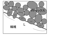
- FIG. 2 is an explanatory diagram of a method of calculating the adhesion rate between the fiber and the matrix (solid line: interface, dotted line: particle adhesion portion).
- the ceramic matrix composite material of the present invention is a ceramic matrix composite material having a modified alumina portion in the gap between the oxide ceramic matrix having an average particle size of 0.05 to 5.0 ⁇ m and the ceramic continuous fiber.
- the oxide ceramic in the oxide ceramic matrix is, for example, a metal oxide, and the type of metal is not particularly limited. However, considering that it has high heat resistance, for example, it can be at least one kind of oxide ceramic selected from the group consisting of alumina, silica, mullite and zirconia.
- the oxide ceramic is preferably at least one kind of oxide ceramic selected from the group consisting of alumina, silica and mullite from the viewpoint of having high heat resistance.
- the particle size of the oxide ceramic matrix can be appropriately determined in consideration of the physical characteristics required for the CMC of the present invention.
- the average particle size of the oxide ceramic matrix is in the range of 0.05 to 5.0 ⁇ m. It is preferably 0.1 to 1.0 ⁇ m, and more preferably 0.2 to 0.7 ⁇ m. When the average particle size is less than 0.05 ⁇ m, the structure is excessively fine, and the modified alumina portion is unlikely to enter the gap between the oxide ceramic matrix and the ceramic continuous fiber. An average particle size larger than 5.0 ⁇ m can result in defects in the ceramic matrix.
- the ceramics in the ceramic continuous fibers may be either oxide ceramics or non-oxide ceramics.
- the oxide ceramic is, for example, a metal oxide, and the type of metal is not particularly limited. Specific examples of the oxide ceramics are the same as those exemplified in the oxide ceramic matrix.
- the non-oxide ceramic can be, for example, silicon carbide, boron nitride or the like.
- the ceramic continuous fiber is not particularly limited as long as it is a continuous fiber composed of ceramics.
- the continuous fiber is a fiber that can use an arbitrary length and can be woven into a two-dimensional or three-dimensional structure.
- the ceramic continuous fiber of the present embodiment is preferably at least one of a fiber bundle state and a woven state of the fiber bundle, and the ceramic continuous fiber in the woven state of the fiber bundle (hereinafter, the continuous fiber is referred to as “ceramics”. It is also referred to as "fiber cloth”).
- the oxide ceramic continuous fiber can be, for example, an alumina continuous fiber, a mullite continuous fiber, or the like, and the non-oxide ceramic continuous fiber can be, for example, a silicon carbide continuous fiber or the like.
- the ceramic continuous fiber is preferably at least one of an alumina continuous fiber and a mullite continuous fiber, and more preferably a mullite continuous fiber.
- the volume ratio of the ceramic continuous fiber content to the ceramic matrix content in the CMC of the present invention is preferably 1: 9 to 9: 1, more preferably 2: 8 to 8: 2.
- the gap between the oxide ceramic matrix and the ceramic continuous fiber means a region including the interface between the oxide ceramic matrix and the ceramic continuous fiber.
- the alumina of the modified alumina portion existing in this gap is ⁇ -alumina or alumina containing ⁇ -alumina.
- the ⁇ -alumina in the modified alumina portion is ⁇ -alumina having a lower crystallinity than the ⁇ -alumina for the oxide ceramic matrix.
- the CMC can be obtained by appropriately fixing the interface between the oxide ceramic matrix and the ceramic continuous fiber.
- the alumina in the modified alumina portion is alumina containing ⁇ -alumina
- the alumina other than ⁇ -alumina is not particularly limited, and may be, for example, ⁇ -alumina and / or ⁇ -alumina.
- ⁇ -alumina having a peak top of 2 ⁇ 43.2 to 43.5 ° can be observed in powder X-ray diffraction is contained. It is preferable from the viewpoint of obtaining the effect of the present invention.
- the strength of CMC tends to decrease.
- the adhesion is too weak, the CMC tends to be broken due to the peeling between the oxide ceramic matrix and the ceramic continuous fiber, and the tensile strength tends to decrease. From this, it is presumed that the CMC of the present invention exhibits high strength because the interface between the ceramic continuous fiber and the oxide ceramic matrix is appropriately fixed by the modified alumina portion.
- the interfacial adhesion rate between the oxide ceramic matrix and the ceramic fiber which is an index of the degree of adhesion between the oxide ceramic matrix and the ceramic continuous fiber, is, for example, 50 to 70%. It is preferably in the range.
- the interface adhesion rate can be determined by the method described in Examples. When the interface adhesion rate is 70% or less, the scratches in the oxide ceramic matrix can be prevented from being deflected at the fiber interface and the scratches penetrating the fibers, and the original damage tolerance of CMC is lost and the tensile strength is lost. Can be avoided from becoming low.
- the interface adhesion rate is more preferably 50 to 65%.
- the content of the modified alumina portion can be in the range of 0.1 to 20% of the total mass of the composite material, and is 0.5 to 15% from the viewpoint of providing CMC having a relatively high tensile strength.
- the range is preferably, more preferably 1 to 13%, still more preferably 2 to 11%.
- the ceramic matrix composite material of the present invention can have a matrix relative density of 50% or more.
- the matrix relative density can be determined by the method described in Examples.
- the relative density of the matrix varies depending on the type and content of the oxide ceramic matrix and ceramic continuous fibers and the content of the modified alumina portion, but this book has a modified alumina portion as compared with CMC which does not have the modified alumina portion.
- the matrix relative density of the CMC of the invention is high, preferably 4.5% or more.
- the higher the matrix relative density the higher the tensile strength of the CMC.
- the relative density of the CMC matrix of the present invention is preferably in the range of 51 to 90%, more preferably in the range of 52 to 85%, and even more preferably in the range of 55 to 80%.
- the CMC of the present invention preferably has a tensile strength (hereinafter, also referred to as “bulk tensile strength”) of 50 to 300 MPa, and particularly preferably 100 to 300 MPa.
- the bulk tensile strength can be measured by using a plate-shaped measurement sample having a width of 10 mm, a length of 100 mm, and a thickness of 2 to 5 mm, and pulling the sample at a load speed of 0.5 mm / min.
- the CMC of the present invention can be a ceramic matrix composite material which is a calcined product of a composite composed of an oxide ceramic matrix and ceramic continuous fibers containing an alkylaluminoxane.
- CMC which is a calcined product
- a calcined product obtained by firing alkylaluminoxane (RAO) in a composite composed of an oxide ceramic matrix and ceramic continuous fibers in a modified alumina portion.
- the RAO calcined product is a calcined product of ethyl aluminoxane and / or methyl aluminoxane, and more preferably a calcined product of ethyl aluminoxane.
- the method for forming the RAO fired product is the method described in the method for producing CMC described later.
- the composite composed of the oxide ceramic matrix and the ceramic continuous fiber containing the alkylaluminoxane is obtained by impregnating the composite composed of the oxide ceramic matrix and the ceramic continuous fiber with the alkylaluminoxane-containing solution and drying. It can be a product of ceramics.
- the fired product can be a fired product in the range of 800 to 1400 ° C., which is a composite composed of an oxide ceramic matrix and ceramic continuous fibers containing an alkylaluminoxane.
- the fired product contains a modified alumina portion, which is a thermal decomposition product of alkylaluminoxane, in the gap between the oxide ceramic matrix and the oxide ceramic continuous fiber.
- the CMC of the present invention can be a composite material that exhibits a matrix relative density increased by 4.5% or more and a tensile strength increased by 5% or more as compared with a ceramic matrix composite material having no modified alumina portion. It is more preferable that the CMC exhibits an interlayer shear strength increased by 5% or more as compared with the ceramic matrix composite material having no modified alumina portion.
- the CMC of the present invention is a CMC having a modified alumina portion because it is produced using a RAO-containing solution, whereas the ceramic matrix composite material having no modified alumina portion does not use a RAO-containing solution and is a matrix. It is obtained by firing a composite of continuous fibers as it is. A composite obtained by firing a composite having the same composition as the composite of the matrix and continuous fibers used in the CMC production of the present invention, which is the object of comparison, under the same firing conditions as the firing conditions in the CMC production of the present invention is obtained. A ceramic matrix composite material having no modified alumina portion is used. The relative density and tensile strength of the CMC matrix and the interlaminar shear strength of the CMC can be measured by the methods shown in the examples.
- the method for producing a ceramic matrix composite material of the present invention is A step of impregnating an alkylaluminoxane-containing solution with a composite composed of an oxide ceramic matrix and ceramic continuous fibers and then drying the mixture one or more times to obtain an alkylaluminoxane-containing precursor, and firing the precursor.
- the step of obtaining the CMC of the invention is included.
- a composite composed of an oxide ceramic matrix and ceramic continuous fibers can be prepared, for example, by mixing the matrix and continuous fibers and then heat-treating the obtained mixture.
- the method of mixing the matrix and the continuous fiber is arbitrary, and examples thereof include a method of impregnating a slurry containing a raw material of the matrix (hereinafter, also referred to as “raw material slurry”) with the continuous fiber.
- raw material slurry a raw material of the matrix
- the mixing ratio of the matrix and the continuous fiber can be appropriately determined in consideration of the material and shape of the matrix and the continuous fiber and the physical characteristics of the final CMC obtained.
- the matrix: continuous fiber is 1: 1.
- the range is 9 to 9: 1, preferably 2: 8 to 8: 2.
- the volume of continuous fibers in CMC is calculated from the weight and density (known) of continuous fibers measured at the time of CMC production, and the volume of CMC is calculated from each length of length, width and thickness of CMC.
- the volume of the matrix is obtained by subtracting the fiber volume from the volume of CMC.
- the heat treatment of the matrix and the continuous fiber can be performed, for example, in the air at 600 ° C. or higher and 1000 ° C. or lower.
- the complex obtained by the heat treatment under these conditions is a so-called "temporary burnt body".
- the operation of impregnating the above complex with an alkylaluminoxane (RAO) -containing solution and then drying is repeated one or more times to obtain a RAO-containing precursor.
- RAO alkylaluminoxane
- the RAO used in the present invention is, for example, aluminaluminoxane represented by the general formula (1).
- Q represents a linear or branched alkyl group having 1 to 4 carbon atoms, a linear or branched alkoxyl group having 1 to 7 carbon atoms, an acyloxy group, or an acetylacetonate group, and m is 1 to 200. Is an integer of.
- Examples of the linear or branched alkyl group having 1 to 4 carbon atoms in Q in the general formula (1) include a methyl group, an ethyl group, a propyl group, an isopropyl group, an n-butyl group, an isobutyl group and a sec-butyl group. Examples thereof include a tert-butyl group.
- Specific examples of the linear or branched alkoxyl group having 1 to 7 carbon atoms include a methoxy group, an ethoxy group, an isopropoxy group, an n-butoxy group, a sec-butoxy group, a t-butoxy group, a phenoxy group and a methoxyethoxy group. Etc. can be raised.
- acyloxy group examples include an acetoxy group, a propionyloxy group, a butyryloxy group, an isobutyryloxy group and the like, and among them, a linear or branched alkyl group having 1 to 4 carbon atoms is particularly preferable.
- it is a methyl group, an ethyl group, a propyl group or the like.
- M in the general formula (1) is an integer in the range of 1 to 200, preferably an integer in the range of 1 to 80.
- RAO examples include methylamylminoxane, ethylaluminoxane, propylaluminoxane and the like, and among them, methylamylminoxane and ethylaluminoxane are preferable.
- the RAO represented by the general formula (1) can be a partial hydrolyzate of an alkylaluminum (hereinafter, may be referred to as AA) compound represented by the following general formula (2).
- the partial hydrolyzate of the AA compound is such that the molar amount of water added to the AA compound in an organic solvent / the molar amount of the AA compound is partially hydrolyzed in the range of, for example, 0.4 to 1.3. Obtained at. That is, the molar amount of the O element / the molar amount of the Al element contained in RAO, which is a partial hydrolyzate, is 0.4 to 1.3.
- R 1 , R 2 , and R 3 are independently hydrogen, a linear or branched alkyl group having 1 to 4 carbon atoms, a linear or branched alkoxyl group having 1 to 7 carbon atoms, and an acyloxy group. Or represents an acetylacetonate group.
- Examples of the linear or branched alkyl group having 1 to 4 carbon atoms in R 1 , R 2 and R 3 of the general formula (2) include methyl group, ethyl group, propyl group, isopropyl group, n-butyl group and isobutyl. Groups, sec-butyl groups, tert-butyl groups and the like can be mentioned.
- the R 1, R 2, R 3 Of these, a methyl group, an ethyl group, a propyl group is preferred, and particularly preferred such as a methyl group, an ethyl group.
- linear or branched alkoxyl group having 1 to 7 carbon atoms include a methoxy group, an ethoxy group, an isopropoxy group, an n-butoxy group, a sec-butoxy group, a t-butoxy group, a phenoxy group and a methoxyethoxy group. Etc. can be raised.
- Specific examples of the acyloxy group include an acetoxy group, a propionyloxy group, a butyryloxy group, an isobutyryloxy group and the like.
- Examples of the AA compound of the general formula (2) include trimethylaluminum, triethylaluminum, and tripropylaluminum, and among them, trimethylaluminum (TMA) and triethylaluminum (TEA) are preferable.
- TMA trimethylaluminum
- TEA triethylaluminum
- the organic solvent used for preparing the partial hydrolyzate may be any one having solubility in the AA compound represented by the general formula (2), for example, an electron-donating organic solvent, a hydrocarbon compound, and a cyclic amide. Compounds and the like can be mentioned. Further, as the organic solvent, a solvent having solubility in water can be used, and an organic solvent having solubility in water and a solvent having low solubility in water can be used in combination.
- the organic solvent can be an electron donating organic solvent, a hydrocarbon compound or a mixture thereof.
- Examples of electron-donating organic solvents include 1,2-diethoxyethane, 1,2-dibutkietan, diethyl ether, din-propyl ether, diisopropyl ether, dibutyl ether, cyclopentylmethyl ether, tetrahydrofuran, dioxane, glyme, diglyme. , Ether-based solvents such as triglime, anisole, and methoxytoluene, amine-based solvents such as trimethylamine, triethylamine, and triphenylamine.
- 1,2-diethoxyethane, tetrahydrofuran and dioxane are preferable.
- hydrocarbon compound examples include a linear or branched hydrocarbon compound having 5 to 20 carbon atoms, more preferably 6 to 12 carbon atoms, and a cyclic hydrocarbon compound having 6 to 20 carbon atoms, more preferably 6 to 6 carbon atoms. Twelve aromatic hydrocarbon compounds and mixtures thereof can be exemplified.
- hydrocarbon compounds include pentane, n-hexane, heptane, isohexane, methylpentane, octane, 2,2,4-trimethylpentane (isooctane), n-nonane, n-decane, n-hexadecan, Alicyclic hydrocarbons such as octadecane, eikosan, methylheptan, 2,2-dimethylhexane, 2-methyloctane; alicyclic hydrocarbons such as cyclopentane, cyclohexanemethylcyclohexane, ethylcyclohexane, benzene, toluene, xylene, cumene, Examples thereof include aromatic hydrocarbons such as trimethylbenzene, and hydrocarbon-based solvents such as mineral spirit, solvent naphtha, kerosine, and petroleum ether.
- Examples of the cyclic amide compound include N-methyl-2-pyrrolidone, 1,3-dimethyl-imidazolidinone, 1,3-dimethyl-3,4,5,6-tetrahydro-2 (1H) -pyrimidinone, and the like.
- N-methyl-2-pyrrolidone is preferable because a mixture thereof can be mentioned and can be obtained at low cost.
- the organic solvent used for the preparation of the partial hydrolyzate is preferably a cyclic amide compound because it is suitable as a solvent for impregnation as it is, and particularly preferably N-methyl-2-pyrrolidone because it can be obtained at low cost.
- Hydrolysis is carried out by adding water or a solution containing water to a solution prepared by dissolving the alkylaluminum compound in the organic solvent, for example, a cyclic amide compound and, if desired, a solvent other than the cyclic amide compound under an inert gas atmosphere. Add and do.
- water itself may be added, it is preferable to add a solution containing water from the viewpoint of controlling heat generation during the reaction between the alkylaluminum compound and water.
- the complex (calcination) obtained by heat-treating the matrix and continuous fibers is impregnated into the RAO-containing solution.
- the RAO concentration of the RAO-containing solution is preferably 0.5 to 40 wt%, more preferably 1 to 30 wt%, and particularly preferably 3 to 15 wt% as the aluminum concentration. If the aluminum concentration of RAO is less than 0.5 wt%, the density improvement by the impregnation treatment may not be sufficiently obtained. Further, if the aluminum concentration of RAO exceeds 40 wt%, it may precipitate as a solid, which may cause problems such as impregnation in the calcined body. By setting the concentration in such a range, the invasion into the complex, especially between the matrices, is promoted, and a high-density CMC can be obtained.
- the solvent for the RAO-containing solution when the matrix is composed of oxides such as alumina, mullite, silica, and zirconia, it is preferable to use a solvent that provides hydrophilicity.
- a solvent that provides hydrophilicity N-methyl-2-pyrrolidone, 1,3-dimethyl-imidazolidinone, 1,3-dimethyl-3 is used from the viewpoint of further improving the stability of RAO in air.
- 4,5,6-tetrahydro-2 (1H) -pyrimidinone and other amide compounds having a cyclic structure or mixtures thereof can be exemplified, and among them, N-methyl-2-pyrrolidone is preferable.
- the amount of metal impurities in RAO is preferably 100 ppm or less, more preferably 10 ppm or less, in order to promote interfacial adhesion in the heat treatment step which is a subsequent step.
- the step of impregnating the RAO solution with the complex is preferably carried out in an inert gas atmosphere because RAO in the RAO-containing solution easily reacts with moisture and oxygen in the air and hydrolyzes.
- the inert atmosphere include a nitrogen atmosphere and an argon atmosphere, and it is preferable to carry out the activity in a nitrogen atmosphere from an economical point of view.
- the impregnation pressure is not particularly limited as long as the RAO-containing solution is sufficiently impregnated between the complex, particularly the matrix, and it is appropriate to set it to, for example, -0.4 to 0.5 MPaG.
- the complex that has been impregnated with the RAO-containing solution is taken out from the inert atmosphere into the air and dried.
- the solvent of the RAO-containing solution is removed by drying.
- RAO reacts rapidly with moisture and oxygen in the air to provide an aluminum-containing solid.
- the aluminum-containing solid material forms an oxide such as alumina by firing described later.
- Drying after impregnation can be performed in the air. Due to drying in the air, at least a part of the impregnated RAO reacts with moisture and oxygen in the air to proceed with hydrolysis.
- the drying temperature after impregnation is preferably, for example, 25 to 120 ° C.
- the operation of heating at a temperature in the range of 100 to 1000 ° C. and lower than the firing temperature can be further included in order to promote the hydrolysis of the RAO.
- Any heat treatment after drying is preferably set to a temperature lower than the firing temperature in the next step from the viewpoint of avoiding thermal deterioration of the continuous fibers.
- the temperature of the heat treatment after drying is, for example, 100 to 1000 ° C, preferably 200 to 900 ° C.
- the RAO-containing precursor can be obtained by performing the impregnation, drying and arbitrary heat treatment once or multiple times in consideration of the concentration, viscosity, RAO impregnation amount, etc. of the RAO-containing solution. It can be appropriately repeated any number of times, for example, in the range of 2 to 15 times, until an RAO-containing precursor having a desired amount of RAO impregnated in the complex is obtained. It is preferably 1 to 10 times, particularly preferably 1 to 7 times. If the number of heat treatments is 15 or less, the RAO-containing precursor can be prepared while suppressing the deterioration of continuous fibers even if the temperature of any heat treatment is relatively high.
- Non-Patent Document 2 When the chlorine-based alumina precursor described in Non-Patent Document 2 is used, in order to impregnate the matrix a plurality of times, the chlorine-based alumina precursor is solidified at 900 ° C. after the impregnation. A degree of heat treatment was required. On the other hand, in the above step, in the drying after impregnation, RAO reacts with moisture and oxygen in the air to proceed with hydrolysis, and at least a part of the RAO becomes a solid substance. Therefore, after the matrix is impregnated and dried, the RAO-containing solution can be impregnated again without heat treatment.
- the use of the RAO-containing solution is suitable for forming an alumina precursor for CMC because it is possible to prevent deterioration of continuous fibers due to heat treatment in this impregnation step. Furthermore, since RAO does not contain chlorine, chlorine is not generated even if the RAO-containing solution is impregnated and heat-treated after drying, and deterioration of continuous fibers due to chlorine can be prevented. Deterioration of continuous fibers can be prevented by heat treatment at a firing temperature (about 1100 ° C.) or lower.
- the precursor obtained after the final drying is calcined.
- the aluminum-containing solid contained in the precursor is modified to aluminum hydroxide, boehmite, ⁇ -alumina, ⁇ -alumina, ⁇ -alumina, etc. by firing, but forms ⁇ -alumina having excellent mechanical properties.
- the firing temperature is preferably 800 to 1400 ° C., more preferably 1000 to 1350 ° C., and particularly preferably 1100 to 1350 ° C. from the viewpoint that the aluminum-containing solid substance derived from RAO forms ⁇ -alumina.
- the temperature is 1400 ° C. or lower, deterioration of the ceramic fiber can be prevented.
- CMC having high strength can be produced by using RAO containing no chlorine.
- the CMC of the present invention has high strength, it is suitable for structural members for aircraft engines, general-purpose industrial members, and the like.
- the XRD measurement was performed using a general powder X-ray diffractometer (device name: UltraIII, manufactured by Rigaku Co., Ltd.).
- the conditions for XRD measurement are as follows.
- Measurement mode Step scan Scan condition: 0.04 ° / s Divergence slit: 2/3 deg Scattering slit: 2/3 deg Light receiving slit: 0.3 mm
- Measurement time 2.0 seconds
- Measurement range: 2 ⁇ 42.5-44.0 °
- the full width at half maximum was determined using Industrial Analysis for Windows (Version 6.0) manufactured by Rigaku.
- Analytic function Divided vote function
- the density ⁇ c is expressed by the following equation (3) using the density ⁇ m of the ceramic matrix and the density ⁇ f of the ceramic continuous fiber.
- ⁇ c is the density of CMC measured by the Archimedes method
- V f is the volume content of continuous ceramic fibers in the CMC sample.
- [rho f is the alumina fiber 3.9 g / cm 3, a mullite fiber using a value of 3.4 g / cm 3.
- the matrix relative density X was obtained from the following equation (5) by dividing the ceramic matrix density ⁇ m by the true density ⁇ 0 of the ceramic matrix.
- the true density ⁇ is the theoretical density of the ceramic powder contained in the raw material slurry. Calculated when the ceramic powder is a mixture of n types of powder, i kind th powder (i 0 ⁇ a natural number of i ⁇ n) by Equation (6) using a theoretical density [rho i and weight content W i of bottom.
- the true density ⁇ 0 of a CMC fired product prepared using a raw material slurry containing a ceramic powder composed of 25% by weight of alumina and 75% by weight of mullite is an alumina true density of 3.98 g / cm 3 and mullite theory. It is calculated as follows by the equation (7) using a density of 3.16 g / cm 3.
- the inter-story shear strength was measured by a method conforming to JIS-R1656 except that the CMC sample was processed into a width of 10 mm, a length of 25 mm, and a thickness of 2 to 4 mm to form a test piece. The width and thickness of the test piece were measured using a micrometer.
- the interlayer shear strength was measured using a strength tester (device name: AG-XPlus, manufactured by Shimadzu Corporation) at a distance between fulcrums of 15 mm and a load speed of 0.05 mm / min. The stress-strain curve was measured, and the interlayer shear strength ⁇ SB was obtained using the following equation (9).
- P max is the maximum load (N)
- b is the width of the test piece (mm)
- h is the thickness of the test piece (mm).
- the tensile strength test was measured by a method conforming to JIS-R1643 except that the CMC sample was processed into a width of 10 mm, a length of 100 mm, and a thickness of 2 to 5 mm to form a tensile test piece with aluminum tabs attached to both ends.
- a tensile test was performed at a load speed of 0.5 mm / min by using a strength tester (device name: AG-XPlus, manufactured by Shimadzu Corporation) and a tensile test jig.
- the width and thickness of the tensile test piece were measured using a micrometer, and the length of the test piece was measured using a caliper.
- the interface adhesion rate between the ceramic matrix and the ceramic fiber was calculated from the interface TEM image of the ceramic matrix and the ceramic fiber.
- the TEM image used for measuring the interface adhesion rate and the conceptual diagram of the method for calculating the interface adhesion rate are shown in FIGS. 1 and 2.
- the interface is represented as a straight line (L) in the TEM image of the interface between the ceramic fiber and the matrix
- Example 1 350 g of ⁇ -alumina powder having an average particle size of 0.19 ⁇ m and 146 g of pure water were mixed with a ball mill for 24 hours to obtain an alumina slurry.
- Alumina fiber cloth (Nextel 610 manufactured by 3M Co., Ltd.) that has been heat-treated in the air at 800 ° C. and desized is laminated with the mixed slurry, impregnated and dried, and molded into a width of 110 mm, a length of 110 mm, and a thickness of about 5.0 mm. I got a body.
- the molded product was dried in the air at 120 ° C. for 24 hours and then fired in the air at 900 ° C. for 2 hours at normal pressure to obtain a calcined product.
- the obtained calcined product was replaced with nitrogen gas (purity 99.999% or more) at 0.3 L / min, and the EAO / NMP solution (Al 2 O 3 concentration: 18. 5 wt%) was impregnated in atmospheric pressure, dried at room temperature, and then heat-treated at 900 ° C. for 2 hours. This impregnation, drying and heat treatment were repeated 3 times. Then, the CMC of the present invention was obtained by firing in the air at 1100 ° C. for 2 hours.
- the obtained CMC contained 42.4 vol% of fibers and 3.8 wt% of the modified alumina portion, had a density of 2.93 g / cm 3 , a matrix relative density of 55.7%, an interlayer shear strength of 15.8 MPa, and a tensile strength.
- the interfacial adhesion rate was 60.9%, and the average particle size of the oxide ceramic matrix was 0.292 ⁇ m.
- the one using the EAO solution as the impregnating solution had improved density, interlayer shear strength, and tensile strength as compared with the non-impregnated solution.
- the matrix relative density of 55.7% is 1.09 times that of the comparison column 1
- the interlayer shear strength of 15.8 MPa is 1.24 times that of the comparison column 1
- the tensile strength 240 MPa is 1.12 times that of the comparison column 1. rice field.
- the interfacial adhesion rate estimated from the TEM was about the same as that of the non-impregnated one, and the matrix could be made denser while suppressing the interfacial adhesion. That is, it is considered that high tensile strength could be obtained because the matrix could be densified while maintaining the damage tolerance.
- Example 2 CMC was obtained in the same manner as in Example 1 except that mullite fiber cloth (3M, Nextel 720) was used instead of alumina fiber cloth (3M, Nextel 610).
- the obtained CMC contained 39.4 vol% of fibers and 3.8 wt% of the modified alumina portion, had a density of 2.82 g / cm 3 , a relative density of the matrix of 61.3%, and an average particle size of the oxide ceramic matrix of 0. It was .280 ⁇ m, the interlayer shear strength was 6.7 MPa, and the tensile strength was 158 MPa.
- the matrix relative density of 61.3% is 1.06 times that of the comparison row 2
- the interlayer shear strength of 6.7 MPa is 1.56 times that of the comparison row 2
- the tensile strength of 158 MPa is 1.13 times that of the comparison row 2.
- the one using the EAO solution as a precursor had improved density, interlayer shear strength, and tensile strength as compared with the non-impregnated one.
- Example 3 A CMC was obtained by the same method as in Example 2 except that the impregnation step, the drying step and the firing step were repeated 5 times.
- the obtained CMC contains 40.0 vol% of fibers and 5.4 wt% of the modified alumina portion, has a density of 2.82 g / cm 3 , a relative density of the matrix of 61.1%, and an average particle size of the oxide ceramic matrix of 0.
- the interlayer shear strength was .275 ⁇ m
- the interlayer shear strength was 6.8 MPa
- the tensile strength was 157 MPa.
- the matrix relative density of 61.1% is 1.06 times that of the comparison column 2
- the interlayer shear strength of 6.8 MPa is 1.58 times that of the comparison column 2
- the tensile strength of 157 MPa is 1.12 times that of the comparison column 2.
- rice field. Density, interlayer shear strength, and tensile strength were improved as compared with non-impregnated.
- Example 4 As the slurry, 181.9 g of ⁇ -alumina powder having an average particle size of 0.19 ⁇ m, 5.6 g of silica powder having an average particle size of 0.20 ⁇ m, and 58 g of pure water were mixed in a ball mill for 24 hours.
- CMC was obtained by the same method as in Example 2 except that the impregnation step, the drying step and the firing step were performed once.
- the obtained CMC contained 36.5 vol% of fibers and 7.3 wt% of the modified alumina portion, had a density of 2.56 g / cm 3 , a relative density of the matrix of 52.7%, and an average particle size of the oxide ceramic matrix of 0.
- the interlayer shear strength was 3.2 MPa
- the tensile strength was 127 MPa.
- the matrix relative density of 52.7% is 1.11 times that of the comparison column 4
- the interlayer shear strength of 3.2 MPa is 1.23 times that of the comparison column 4
- the tensile strength 127 MPa is 1.92 times that of the comparison column 4.
- rice field. Density, interlayer shear strength, and tensile strength were improved as compared with non-impregnated.
- Example 5 In the impregnation step, CMC was obtained by the same method as in Example 1 except that the MAO / NMP solution was used instead of the EAO / NMP solution.
- the obtained CMC contains 42.1 vol% of fibers and 8.9 wt% of the modified alumina portion, has a density of 2.86 g / cm 3 , a relative density of the matrix of 61.7%, and an average particle size of the oxide ceramic matrix of 0. It was .245 ⁇ m, the interlayer shear strength was 13.2 MPa, and the tensile strength was 234 MPa.
- the matrix relative density of 61.7% was 1.21 times that of the comparison column 1, and the interlayer shear strength of 13.2 MPa was 1.04 times that of the comparison column 1. Density and interlayer shear strength were improved compared to non-impregnation.
- Comparative Example 1 CMC was obtained in the same manner as in Example 1 except that the calcined product was not impregnated with the EAO / NMP solution.
- the obtained CMC contained 42.4 vol% fibers, a density of 2.82 g / cm 3 , a matrix relative density of 50.9%, an oxide ceramic matrix average particle size of 0.213 ⁇ m, and an interlayer shear strength of 12.
- the tensile strength was 2.7 MPa, the interfacial adhesion rate was 57.0%.
- the density, low interlaminar shear strength, and low tensile strength were lower than those treated with the EAO solution impregnated.
- Comparative Example 2 CMC was obtained in the same manner as in Example 2 except that the calcined product was not impregnated with the EAO / NMP solution.
- the obtained CMC contained 39.4 vol% fibers, a density of 2.73 g / cm 3 , a matrix relative density of 57.6%, an oxide ceramic matrix average particle size of 0.210 ⁇ m, and an interlayer shear strength of 4. It was 0.3 MPa and the tensile strength was 140 MPa. The density, low interlaminar shear strength, and low tensile strength were lower than those treated with the EAO solution impregnated.
- Comparative Example 4 CMC was obtained in the same manner as in Example 4 except that the calcined product was not impregnated with the EAO / NMP solution.
- the obtained CMC contained 39.2 vol% fibers, a density of 2.47 g / cm 3 , a matrix relative density of 47.3%, an oxide ceramic matrix average particle size of 0.192 ⁇ m, and an interlayer shear strength of 2. It was 0.6 MPa and the tensile strength was 66 MPa. The density, low interlaminar shear strength, and low tensile strength were lower than those treated with the EAO solution impregnated.
- Reference example 1 The EAO / NMP solution was hydrolyzed at room temperature and then heat-treated at 900 ° C. for 2 hours and 1100 ° C. for 2 hours to obtain ⁇ -alumina corresponding to the modified alumina portion.
- the obtained powder was pulverized in an alumina mortar for 25 minutes, and then XRD measurement of the obtained product was performed.
- Reference example 2 The MAO / NMP solution was hydrolyzed at room temperature and then heat-treated at 900 ° C. for 2 hours and 1100 ° C. for 2 hours to obtain ⁇ -alumina corresponding to the modified alumina portion.
- the obtained powder was pulverized in an alumina mortar for 25 minutes, and then XRD measurement of the obtained product was performed.
- the half width obtained was 0.256 °.
- Table 1 shows an outline of the experimental conditions of Examples 1 to 5 and Comparative Examples 1 to 4, and Table 2 shows a summary of the experimental results.
- the present invention is useful in fields related to CMC.
Landscapes
- Chemical & Material Sciences (AREA)
- Engineering & Computer Science (AREA)
- Ceramic Engineering (AREA)
- Materials Engineering (AREA)
- Structural Engineering (AREA)
- Organic Chemistry (AREA)
- Chemical Kinetics & Catalysis (AREA)
- Manufacturing & Machinery (AREA)
- Inorganic Chemistry (AREA)
- Compositions Of Oxide Ceramics (AREA)
Priority Applications (1)
| Application Number | Priority Date | Filing Date | Title |
|---|---|---|---|
| JP2022510658A JP7372448B2 (ja) | 2020-03-27 | 2021-03-25 | セラミックスマトリックス複合材料及びその製造方法 |
Applications Claiming Priority (2)
| Application Number | Priority Date | Filing Date | Title |
|---|---|---|---|
| JP2020058286 | 2020-03-27 | ||
| JP2020-058286 | 2020-03-27 |
Publications (1)
| Publication Number | Publication Date |
|---|---|
| WO2021193817A1 true WO2021193817A1 (ja) | 2021-09-30 |
Family
ID=77892246
Family Applications (1)
| Application Number | Title | Priority Date | Filing Date |
|---|---|---|---|
| PCT/JP2021/012517 Ceased WO2021193817A1 (ja) | 2020-03-27 | 2021-03-25 | セラミックスマトリックス複合材料及びその製造方法 |
Country Status (2)
| Country | Link |
|---|---|
| JP (1) | JP7372448B2 (https=) |
| WO (1) | WO2021193817A1 (https=) |
Cited By (1)
| Publication number | Priority date | Publication date | Assignee | Title |
|---|---|---|---|---|
| WO2023248910A1 (ja) | 2022-06-21 | 2023-12-28 | 東ソー株式会社 | セラミックマトリックス複合材料及びその製造方法 |
Citations (5)
| Publication number | Priority date | Publication date | Assignee | Title |
|---|---|---|---|---|
| JPS63291880A (ja) * | 1987-05-26 | 1988-11-29 | Teijin Ltd | 繊維強化セラミック焼結成形品の製造方法 |
| JPH03223179A (ja) * | 1990-01-26 | 1991-10-02 | Ishikawajima Harima Heavy Ind Co Ltd | 繊維強化無機系材料の製造方法 |
| JPH1149570A (ja) * | 1997-07-30 | 1999-02-23 | Nippon Carbon Co Ltd | SiC繊維強化SiC複合材料 |
| JP2013511467A (ja) * | 2009-11-23 | 2013-04-04 | アプライド ナノストラクチャード ソリューションズ リミテッド ライアビリティー カンパニー | カーボンナノチューブ浸出繊維材料を含有するセラミック複合材料とその製造方法 |
| WO2018105670A1 (ja) * | 2016-12-07 | 2018-06-14 | 三菱重工航空エンジン株式会社 | セラミックス基複合材料の製造方法 |
-
2021
- 2021-03-25 WO PCT/JP2021/012517 patent/WO2021193817A1/ja not_active Ceased
- 2021-03-25 JP JP2022510658A patent/JP7372448B2/ja active Active
Patent Citations (5)
| Publication number | Priority date | Publication date | Assignee | Title |
|---|---|---|---|---|
| JPS63291880A (ja) * | 1987-05-26 | 1988-11-29 | Teijin Ltd | 繊維強化セラミック焼結成形品の製造方法 |
| JPH03223179A (ja) * | 1990-01-26 | 1991-10-02 | Ishikawajima Harima Heavy Ind Co Ltd | 繊維強化無機系材料の製造方法 |
| JPH1149570A (ja) * | 1997-07-30 | 1999-02-23 | Nippon Carbon Co Ltd | SiC繊維強化SiC複合材料 |
| JP2013511467A (ja) * | 2009-11-23 | 2013-04-04 | アプライド ナノストラクチャード ソリューションズ リミテッド ライアビリティー カンパニー | カーボンナノチューブ浸出繊維材料を含有するセラミック複合材料とその製造方法 |
| WO2018105670A1 (ja) * | 2016-12-07 | 2018-06-14 | 三菱重工航空エンジン株式会社 | セラミックス基複合材料の製造方法 |
Cited By (1)
| Publication number | Priority date | Publication date | Assignee | Title |
|---|---|---|---|---|
| WO2023248910A1 (ja) | 2022-06-21 | 2023-12-28 | 東ソー株式会社 | セラミックマトリックス複合材料及びその製造方法 |
Also Published As
| Publication number | Publication date |
|---|---|
| JPWO2021193817A1 (https=) | 2021-09-30 |
| JP7372448B2 (ja) | 2023-10-31 |
Similar Documents
| Publication | Publication Date | Title |
|---|---|---|
| EP2239245A1 (en) | Aluminum magnesium titanate - alumina composite ceramic | |
| Chawla | Ceramic matrix composites | |
| Biswas | Solid state sintering of SiC-ceramics | |
| Zhang et al. | In situ reaction synthesis of silicon carbide–boron nitride composites | |
| Poges et al. | Preparation and characterization of an oxide-oxide continuous fiber reinforced ceramic matrix composite with a zinc oxide interphase | |
| Fan et al. | Fabrication and properties of Si2N2O ceramics for microwave sintering furnace | |
| WO2022071218A1 (ja) | 金属元素を有するセラミックス連続繊維およびそれを用いたセラミックマトリックス複合材料 | |
| Ewais et al. | Investigation of the effect of ZrO2 and ZrO2/Al2O3 additions on the hot-pressing and properties of equimolecular mixtures of α-and β-Si3N4 | |
| KR102054373B1 (ko) | 내환경 코팅재가 코팅된 구조체 및 상기 내환경 코팅재를 코팅하는 방법. | |
| WO2021193817A1 (ja) | セラミックスマトリックス複合材料及びその製造方法 | |
| Hossain et al. | Development of waste derived nano-lakargiite bonded high alumina refractory castable for high temperature applications | |
| Zabelina et al. | SiC composites containing carbon nanotubes and oxide additives based on organoelementoxanes. Preparation by spark plasma sintering | |
| Wang et al. | Corrosion behavior of pyrocarbon coatings exposed to Al2O3–SiO2 gels containing ammonium nitrate | |
| TWI746750B (zh) | 配向AlN燒結體及其製法 | |
| KITAYAMA et al. | High hardness α-Si3N4 ceramics reinforced by rod-like β-Si3N4 seed particles | |
| Belhouchet et al. | Elaboration and characterization of mullite–zirconia composites from gibbsite, boehmite and zircon | |
| Son et al. | High-strength pseudobrookite-type MgTi2O5 by spark plasma sintering | |
| Belhouchet et al. | Characterization of mullite-zirconia composites prepared from various starting alumina phases | |
| JP2008297134A (ja) | 炭化硼素質焼結体および防護部材 | |
| Lee et al. | Synthesis of mono-phase, hexagonal plate-like Al4SiC4 powder via a carbothermal reduction process | |
| US7955579B2 (en) | Boron suboxide composite material | |
| Duran et al. | Templated grain growth of textured mullite/zirconia composites | |
| Ivicheva et al. | Features of the phase composition and morphology of the particles of sialon synthesized from silicon and aluminum nitrides | |
| Muhammad et al. | Synthesis, characterization and mechanical properties of alumina–zirconia nanocomposite particles | |
| Liu et al. | Composite thermal protection coating on woven silica fiber fabrics |
Legal Events
| Date | Code | Title | Description |
|---|---|---|---|
| 121 | Ep: the epo has been informed by wipo that ep was designated in this application |
Ref document number: 21775679 Country of ref document: EP Kind code of ref document: A1 |
|
| ENP | Entry into the national phase |
Ref document number: 2022510658 Country of ref document: JP Kind code of ref document: A |
|
| NENP | Non-entry into the national phase |
Ref country code: DE |
|
| 122 | Ep: pct application non-entry in european phase |
Ref document number: 21775679 Country of ref document: EP Kind code of ref document: A1 |