WO2021193643A1 - 複合部材の製造方法および複合部材 - Google Patents
複合部材の製造方法および複合部材 Download PDFInfo
- Publication number
- WO2021193643A1 WO2021193643A1 PCT/JP2021/012011 JP2021012011W WO2021193643A1 WO 2021193643 A1 WO2021193643 A1 WO 2021193643A1 JP 2021012011 W JP2021012011 W JP 2021012011W WO 2021193643 A1 WO2021193643 A1 WO 2021193643A1
- Authority
- WO
- WIPO (PCT)
- Prior art keywords
- porous film
- resin
- metal
- composite
- composite member
- Prior art date
Links
- 239000002131 composite material Substances 0.000 title claims abstract description 111
- 238000000034 method Methods 0.000 title claims abstract description 69
- 238000004519 manufacturing process Methods 0.000 title claims abstract description 48
- 229910052751 metal Inorganic materials 0.000 claims abstract description 152
- 239000002184 metal Substances 0.000 claims abstract description 152
- 229920005989 resin Polymers 0.000 claims abstract description 110
- 239000011347 resin Substances 0.000 claims abstract description 110
- 239000000843 powder Substances 0.000 claims abstract description 40
- 239000007921 spray Substances 0.000 claims description 28
- 239000000463 material Substances 0.000 claims description 25
- 238000010438 heat treatment Methods 0.000 claims description 16
- 229920005992 thermoplastic resin Polymers 0.000 claims description 10
- 229920001187 thermosetting polymer Polymers 0.000 claims description 7
- 239000012779 reinforcing material Substances 0.000 claims description 4
- 238000003825 pressing Methods 0.000 claims description 3
- 238000005304 joining Methods 0.000 abstract description 28
- 238000010288 cold spraying Methods 0.000 abstract 1
- 238000000879 optical micrograph Methods 0.000 description 18
- 238000011282 treatment Methods 0.000 description 17
- 239000004696 Poly ether ether ketone Substances 0.000 description 14
- 229920002530 polyetherether ketone Polymers 0.000 description 14
- 238000012360 testing method Methods 0.000 description 14
- 239000002245 particle Substances 0.000 description 13
- 238000009864 tensile test Methods 0.000 description 12
- 229910000838 Al alloy Inorganic materials 0.000 description 11
- 239000011148 porous material Substances 0.000 description 11
- 238000003756 stirring Methods 0.000 description 10
- 238000003466 welding Methods 0.000 description 10
- 239000000853 adhesive Substances 0.000 description 7
- 230000001070 adhesive effect Effects 0.000 description 7
- 229920002292 Nylon 6 Polymers 0.000 description 6
- 229910001069 Ti alloy Inorganic materials 0.000 description 6
- 238000011049 filling Methods 0.000 description 6
- 239000012528 membrane Substances 0.000 description 6
- RTAQQCXQSZGOHL-UHFFFAOYSA-N Titanium Chemical compound [Ti] RTAQQCXQSZGOHL-UHFFFAOYSA-N 0.000 description 5
- PNEYBMLMFCGWSK-UHFFFAOYSA-N aluminium oxide Inorganic materials [O-2].[O-2].[O-2].[Al+3].[Al+3] PNEYBMLMFCGWSK-UHFFFAOYSA-N 0.000 description 5
- 230000015572 biosynthetic process Effects 0.000 description 5
- 238000004140 cleaning Methods 0.000 description 5
- 239000011800 void material Substances 0.000 description 5
- 229910052782 aluminium Inorganic materials 0.000 description 4
- 238000002844 melting Methods 0.000 description 4
- 230000008018 melting Effects 0.000 description 4
- 230000035515 penetration Effects 0.000 description 4
- 239000000523 sample Substances 0.000 description 4
- 238000001878 scanning electron micrograph Methods 0.000 description 4
- 239000010936 titanium Substances 0.000 description 4
- XAGFODPZIPBFFR-UHFFFAOYSA-N aluminium Chemical compound [Al] XAGFODPZIPBFFR-UHFFFAOYSA-N 0.000 description 3
- 238000005422 blasting Methods 0.000 description 3
- 238000003486 chemical etching Methods 0.000 description 3
- 230000000052 comparative effect Effects 0.000 description 3
- 238000009826 distribution Methods 0.000 description 3
- 230000000694 effects Effects 0.000 description 3
- 238000007731 hot pressing Methods 0.000 description 3
- 239000007788 liquid Substances 0.000 description 3
- 229910052719 titanium Inorganic materials 0.000 description 3
- 239000002699 waste material Substances 0.000 description 3
- 229910018072 Al 2 O 3 Inorganic materials 0.000 description 2
- 230000003247 decreasing effect Effects 0.000 description 2
- 238000013007 heat curing Methods 0.000 description 2
- 238000003780 insertion Methods 0.000 description 2
- 230000037431 insertion Effects 0.000 description 2
- 238000005259 measurement Methods 0.000 description 2
- 150000002739 metals Chemical class 0.000 description 2
- 239000002994 raw material Substances 0.000 description 2
- 238000007788 roughening Methods 0.000 description 2
- 239000000243 solution Substances 0.000 description 2
- 229910000883 Ti6Al4V Inorganic materials 0.000 description 1
- 239000000956 alloy Substances 0.000 description 1
- 238000004458 analytical method Methods 0.000 description 1
- 238000004364 calculation method Methods 0.000 description 1
- 238000001816 cooling Methods 0.000 description 1
- 238000005260 corrosion Methods 0.000 description 1
- 230000007797 corrosion Effects 0.000 description 1
- 238000000354 decomposition reaction Methods 0.000 description 1
- 238000005238 degreasing Methods 0.000 description 1
- 238000011156 evaluation Methods 0.000 description 1
- -1 for example Inorganic materials 0.000 description 1
- 238000002347 injection Methods 0.000 description 1
- 239000007924 injection Substances 0.000 description 1
- 238000001746 injection moulding Methods 0.000 description 1
- 238000000465 moulding Methods 0.000 description 1
- 230000003647 oxidation Effects 0.000 description 1
- 238000007254 oxidation reaction Methods 0.000 description 1
- 238000012545 processing Methods 0.000 description 1
- 238000005096 rolling process Methods 0.000 description 1
- 229920006395 saturated elastomer Polymers 0.000 description 1
- 239000010935 stainless steel Substances 0.000 description 1
- 229910001220 stainless steel Inorganic materials 0.000 description 1
- 239000000126 substance Substances 0.000 description 1
- 239000000758 substrate Substances 0.000 description 1
- 238000010998 test method Methods 0.000 description 1
- 238000004627 transmission electron microscopy Methods 0.000 description 1
Images


Classifications
-
- B—PERFORMING OPERATIONS; TRANSPORTING
- B29—WORKING OF PLASTICS; WORKING OF SUBSTANCES IN A PLASTIC STATE IN GENERAL
- B29C—SHAPING OR JOINING OF PLASTICS; SHAPING OF MATERIAL IN A PLASTIC STATE, NOT OTHERWISE PROVIDED FOR; AFTER-TREATMENT OF THE SHAPED PRODUCTS, e.g. REPAIRING
- B29C65/00—Joining or sealing of preformed parts, e.g. welding of plastics materials; Apparatus therefor
- B29C65/02—Joining or sealing of preformed parts, e.g. welding of plastics materials; Apparatus therefor by heating, with or without pressure
- B29C65/06—Joining or sealing of preformed parts, e.g. welding of plastics materials; Apparatus therefor by heating, with or without pressure using friction, e.g. spin welding
- B29C65/0681—Joining or sealing of preformed parts, e.g. welding of plastics materials; Apparatus therefor by heating, with or without pressure using friction, e.g. spin welding created by a tool
-
- B—PERFORMING OPERATIONS; TRANSPORTING
- B23—MACHINE TOOLS; METAL-WORKING NOT OTHERWISE PROVIDED FOR
- B23K—SOLDERING OR UNSOLDERING; WELDING; CLADDING OR PLATING BY SOLDERING OR WELDING; CUTTING BY APPLYING HEAT LOCALLY, e.g. FLAME CUTTING; WORKING BY LASER BEAM
- B23K20/00—Non-electric welding by applying impact or other pressure, with or without the application of heat, e.g. cladding or plating
- B23K20/12—Non-electric welding by applying impact or other pressure, with or without the application of heat, e.g. cladding or plating the heat being generated by friction; Friction welding
-
- B—PERFORMING OPERATIONS; TRANSPORTING
- B29—WORKING OF PLASTICS; WORKING OF SUBSTANCES IN A PLASTIC STATE IN GENERAL
- B29C—SHAPING OR JOINING OF PLASTICS; SHAPING OF MATERIAL IN A PLASTIC STATE, NOT OTHERWISE PROVIDED FOR; AFTER-TREATMENT OF THE SHAPED PRODUCTS, e.g. REPAIRING
- B29C65/00—Joining or sealing of preformed parts, e.g. welding of plastics materials; Apparatus therefor
- B29C65/02—Joining or sealing of preformed parts, e.g. welding of plastics materials; Apparatus therefor by heating, with or without pressure
- B29C65/44—Joining a heated non plastics element to a plastics element
-
- B—PERFORMING OPERATIONS; TRANSPORTING
- B29—WORKING OF PLASTICS; WORKING OF SUBSTANCES IN A PLASTIC STATE IN GENERAL
- B29C—SHAPING OR JOINING OF PLASTICS; SHAPING OF MATERIAL IN A PLASTIC STATE, NOT OTHERWISE PROVIDED FOR; AFTER-TREATMENT OF THE SHAPED PRODUCTS, e.g. REPAIRING
- B29C65/00—Joining or sealing of preformed parts, e.g. welding of plastics materials; Apparatus therefor
- B29C65/82—Testing the joint
- B29C65/8207—Testing the joint by mechanical methods
- B29C65/8215—Tensile tests
-
- B—PERFORMING OPERATIONS; TRANSPORTING
- B29—WORKING OF PLASTICS; WORKING OF SUBSTANCES IN A PLASTIC STATE IN GENERAL
- B29C—SHAPING OR JOINING OF PLASTICS; SHAPING OF MATERIAL IN A PLASTIC STATE, NOT OTHERWISE PROVIDED FOR; AFTER-TREATMENT OF THE SHAPED PRODUCTS, e.g. REPAIRING
- B29C65/00—Joining or sealing of preformed parts, e.g. welding of plastics materials; Apparatus therefor
- B29C65/82—Testing the joint
- B29C65/8253—Testing the joint by the use of waves or particle radiation, e.g. visual examination, scanning electron microscopy, or X-rays
-
- B—PERFORMING OPERATIONS; TRANSPORTING
- B29—WORKING OF PLASTICS; WORKING OF SUBSTANCES IN A PLASTIC STATE IN GENERAL
- B29C—SHAPING OR JOINING OF PLASTICS; SHAPING OF MATERIAL IN A PLASTIC STATE, NOT OTHERWISE PROVIDED FOR; AFTER-TREATMENT OF THE SHAPED PRODUCTS, e.g. REPAIRING
- B29C66/00—General aspects of processes or apparatus for joining preformed parts
- B29C66/01—General aspects dealing with the joint area or with the area to be joined
- B29C66/05—Particular design of joint configurations
- B29C66/10—Particular design of joint configurations particular design of the joint cross-sections
- B29C66/11—Joint cross-sections comprising a single joint-segment, i.e. one of the parts to be joined comprising a single joint-segment in the joint cross-section
- B29C66/112—Single lapped joints
- B29C66/1122—Single lap to lap joints, i.e. overlap joints
-
- B—PERFORMING OPERATIONS; TRANSPORTING
- B29—WORKING OF PLASTICS; WORKING OF SUBSTANCES IN A PLASTIC STATE IN GENERAL
- B29C—SHAPING OR JOINING OF PLASTICS; SHAPING OF MATERIAL IN A PLASTIC STATE, NOT OTHERWISE PROVIDED FOR; AFTER-TREATMENT OF THE SHAPED PRODUCTS, e.g. REPAIRING
- B29C66/00—General aspects of processes or apparatus for joining preformed parts
- B29C66/01—General aspects dealing with the joint area or with the area to be joined
- B29C66/05—Particular design of joint configurations
- B29C66/303—Particular design of joint configurations the joint involving an anchoring effect
- B29C66/3032—Particular design of joint configurations the joint involving an anchoring effect making use of protrusions or cavities belonging to at least one of the parts to be joined
- B29C66/30321—Particular design of joint configurations the joint involving an anchoring effect making use of protrusions or cavities belonging to at least one of the parts to be joined making use of protrusions belonging to at least one of the parts to be joined
- B29C66/30322—Particular design of joint configurations the joint involving an anchoring effect making use of protrusions or cavities belonging to at least one of the parts to be joined making use of protrusions belonging to at least one of the parts to be joined in the form of rugosity
-
- B—PERFORMING OPERATIONS; TRANSPORTING
- B29—WORKING OF PLASTICS; WORKING OF SUBSTANCES IN A PLASTIC STATE IN GENERAL
- B29C—SHAPING OR JOINING OF PLASTICS; SHAPING OF MATERIAL IN A PLASTIC STATE, NOT OTHERWISE PROVIDED FOR; AFTER-TREATMENT OF THE SHAPED PRODUCTS, e.g. REPAIRING
- B29C66/00—General aspects of processes or apparatus for joining preformed parts
- B29C66/01—General aspects dealing with the joint area or with the area to be joined
- B29C66/05—Particular design of joint configurations
- B29C66/303—Particular design of joint configurations the joint involving an anchoring effect
- B29C66/3032—Particular design of joint configurations the joint involving an anchoring effect making use of protrusions or cavities belonging to at least one of the parts to be joined
- B29C66/30325—Particular design of joint configurations the joint involving an anchoring effect making use of protrusions or cavities belonging to at least one of the parts to be joined making use of cavities belonging to at least one of the parts to be joined
- B29C66/30326—Particular design of joint configurations the joint involving an anchoring effect making use of protrusions or cavities belonging to at least one of the parts to be joined making use of cavities belonging to at least one of the parts to be joined in the form of porosity
-
- B—PERFORMING OPERATIONS; TRANSPORTING
- B29—WORKING OF PLASTICS; WORKING OF SUBSTANCES IN A PLASTIC STATE IN GENERAL
- B29C—SHAPING OR JOINING OF PLASTICS; SHAPING OF MATERIAL IN A PLASTIC STATE, NOT OTHERWISE PROVIDED FOR; AFTER-TREATMENT OF THE SHAPED PRODUCTS, e.g. REPAIRING
- B29C66/00—General aspects of processes or apparatus for joining preformed parts
- B29C66/40—General aspects of joining substantially flat articles, e.g. plates, sheets or web-like materials; Making flat seams in tubular or hollow articles; Joining single elements to substantially flat surfaces
- B29C66/41—Joining substantially flat articles ; Making flat seams in tubular or hollow articles
- B29C66/43—Joining a relatively small portion of the surface of said articles
-
- B—PERFORMING OPERATIONS; TRANSPORTING
- B29—WORKING OF PLASTICS; WORKING OF SUBSTANCES IN A PLASTIC STATE IN GENERAL
- B29C—SHAPING OR JOINING OF PLASTICS; SHAPING OF MATERIAL IN A PLASTIC STATE, NOT OTHERWISE PROVIDED FOR; AFTER-TREATMENT OF THE SHAPED PRODUCTS, e.g. REPAIRING
- B29C66/00—General aspects of processes or apparatus for joining preformed parts
- B29C66/70—General aspects of processes or apparatus for joining preformed parts characterised by the composition, physical properties or the structure of the material of the parts to be joined; Joining with non-plastics material
- B29C66/71—General aspects of processes or apparatus for joining preformed parts characterised by the composition, physical properties or the structure of the material of the parts to be joined; Joining with non-plastics material characterised by the composition of the plastics material of the parts to be joined
-
- B—PERFORMING OPERATIONS; TRANSPORTING
- B29—WORKING OF PLASTICS; WORKING OF SUBSTANCES IN A PLASTIC STATE IN GENERAL
- B29C—SHAPING OR JOINING OF PLASTICS; SHAPING OF MATERIAL IN A PLASTIC STATE, NOT OTHERWISE PROVIDED FOR; AFTER-TREATMENT OF THE SHAPED PRODUCTS, e.g. REPAIRING
- B29C66/00—General aspects of processes or apparatus for joining preformed parts
- B29C66/70—General aspects of processes or apparatus for joining preformed parts characterised by the composition, physical properties or the structure of the material of the parts to be joined; Joining with non-plastics material
- B29C66/73—General aspects of processes or apparatus for joining preformed parts characterised by the composition, physical properties or the structure of the material of the parts to be joined; Joining with non-plastics material characterised by the intensive physical properties of the material of the parts to be joined, by the optical properties of the material of the parts to be joined, by the extensive physical properties of the parts to be joined, by the state of the material of the parts to be joined or by the material of the parts to be joined being a thermoplastic or a thermoset
- B29C66/739—General aspects of processes or apparatus for joining preformed parts characterised by the composition, physical properties or the structure of the material of the parts to be joined; Joining with non-plastics material characterised by the intensive physical properties of the material of the parts to be joined, by the optical properties of the material of the parts to be joined, by the extensive physical properties of the parts to be joined, by the state of the material of the parts to be joined or by the material of the parts to be joined being a thermoplastic or a thermoset characterised by the material of the parts to be joined being a thermoplastic or a thermoset
- B29C66/7392—General aspects of processes or apparatus for joining preformed parts characterised by the composition, physical properties or the structure of the material of the parts to be joined; Joining with non-plastics material characterised by the intensive physical properties of the material of the parts to be joined, by the optical properties of the material of the parts to be joined, by the extensive physical properties of the parts to be joined, by the state of the material of the parts to be joined or by the material of the parts to be joined being a thermoplastic or a thermoset characterised by the material of the parts to be joined being a thermoplastic or a thermoset characterised by the material of at least one of the parts being a thermoplastic
-
- B—PERFORMING OPERATIONS; TRANSPORTING
- B29—WORKING OF PLASTICS; WORKING OF SUBSTANCES IN A PLASTIC STATE IN GENERAL
- B29C—SHAPING OR JOINING OF PLASTICS; SHAPING OF MATERIAL IN A PLASTIC STATE, NOT OTHERWISE PROVIDED FOR; AFTER-TREATMENT OF THE SHAPED PRODUCTS, e.g. REPAIRING
- B29C66/00—General aspects of processes or apparatus for joining preformed parts
- B29C66/70—General aspects of processes or apparatus for joining preformed parts characterised by the composition, physical properties or the structure of the material of the parts to be joined; Joining with non-plastics material
- B29C66/74—Joining plastics material to non-plastics material
- B29C66/742—Joining plastics material to non-plastics material to metals or their alloys
- B29C66/7422—Aluminium or alloys of aluminium
-
- B—PERFORMING OPERATIONS; TRANSPORTING
- B29—WORKING OF PLASTICS; WORKING OF SUBSTANCES IN A PLASTIC STATE IN GENERAL
- B29C—SHAPING OR JOINING OF PLASTICS; SHAPING OF MATERIAL IN A PLASTIC STATE, NOT OTHERWISE PROVIDED FOR; AFTER-TREATMENT OF THE SHAPED PRODUCTS, e.g. REPAIRING
- B29C66/00—General aspects of processes or apparatus for joining preformed parts
- B29C66/80—General aspects of machine operations or constructions and parts thereof
- B29C66/83—General aspects of machine operations or constructions and parts thereof characterised by the movement of the joining or pressing tools
- B29C66/836—Moving relative to and tangentially to the parts to be joined, e.g. transversely to the displacement of the parts to be joined, e.g. using a X-Y table
-
- C—CHEMISTRY; METALLURGY
- C23—COATING METALLIC MATERIAL; COATING MATERIAL WITH METALLIC MATERIAL; CHEMICAL SURFACE TREATMENT; DIFFUSION TREATMENT OF METALLIC MATERIAL; COATING BY VACUUM EVAPORATION, BY SPUTTERING, BY ION IMPLANTATION OR BY CHEMICAL VAPOUR DEPOSITION, IN GENERAL; INHIBITING CORROSION OF METALLIC MATERIAL OR INCRUSTATION IN GENERAL
- C23C—COATING METALLIC MATERIAL; COATING MATERIAL WITH METALLIC MATERIAL; SURFACE TREATMENT OF METALLIC MATERIAL BY DIFFUSION INTO THE SURFACE, BY CHEMICAL CONVERSION OR SUBSTITUTION; COATING BY VACUUM EVAPORATION, BY SPUTTERING, BY ION IMPLANTATION OR BY CHEMICAL VAPOUR DEPOSITION, IN GENERAL
- C23C24/00—Coating starting from inorganic powder
- C23C24/02—Coating starting from inorganic powder by application of pressure only
- C23C24/04—Impact or kinetic deposition of particles
-
- B—PERFORMING OPERATIONS; TRANSPORTING
- B29—WORKING OF PLASTICS; WORKING OF SUBSTANCES IN A PLASTIC STATE IN GENERAL
- B29C—SHAPING OR JOINING OF PLASTICS; SHAPING OF MATERIAL IN A PLASTIC STATE, NOT OTHERWISE PROVIDED FOR; AFTER-TREATMENT OF THE SHAPED PRODUCTS, e.g. REPAIRING
- B29C2791/00—Shaping characteristics in general
- B29C2791/003—Making articles of indefinite length
-
- B—PERFORMING OPERATIONS; TRANSPORTING
- B29—WORKING OF PLASTICS; WORKING OF SUBSTANCES IN A PLASTIC STATE IN GENERAL
- B29C—SHAPING OR JOINING OF PLASTICS; SHAPING OF MATERIAL IN A PLASTIC STATE, NOT OTHERWISE PROVIDED FOR; AFTER-TREATMENT OF THE SHAPED PRODUCTS, e.g. REPAIRING
- B29C66/00—General aspects of processes or apparatus for joining preformed parts
- B29C66/70—General aspects of processes or apparatus for joining preformed parts characterised by the composition, physical properties or the structure of the material of the parts to be joined; Joining with non-plastics material
- B29C66/72—General aspects of processes or apparatus for joining preformed parts characterised by the composition, physical properties or the structure of the material of the parts to be joined; Joining with non-plastics material characterised by the structure of the material of the parts to be joined
- B29C66/721—Fibre-reinforced materials
-
- B—PERFORMING OPERATIONS; TRANSPORTING
- B29—WORKING OF PLASTICS; WORKING OF SUBSTANCES IN A PLASTIC STATE IN GENERAL
- B29C—SHAPING OR JOINING OF PLASTICS; SHAPING OF MATERIAL IN A PLASTIC STATE, NOT OTHERWISE PROVIDED FOR; AFTER-TREATMENT OF THE SHAPED PRODUCTS, e.g. REPAIRING
- B29C66/00—General aspects of processes or apparatus for joining preformed parts
- B29C66/70—General aspects of processes or apparatus for joining preformed parts characterised by the composition, physical properties or the structure of the material of the parts to be joined; Joining with non-plastics material
- B29C66/73—General aspects of processes or apparatus for joining preformed parts characterised by the composition, physical properties or the structure of the material of the parts to be joined; Joining with non-plastics material characterised by the intensive physical properties of the material of the parts to be joined, by the optical properties of the material of the parts to be joined, by the extensive physical properties of the parts to be joined, by the state of the material of the parts to be joined or by the material of the parts to be joined being a thermoplastic or a thermoset
- B29C66/739—General aspects of processes or apparatus for joining preformed parts characterised by the composition, physical properties or the structure of the material of the parts to be joined; Joining with non-plastics material characterised by the intensive physical properties of the material of the parts to be joined, by the optical properties of the material of the parts to be joined, by the extensive physical properties of the parts to be joined, by the state of the material of the parts to be joined or by the material of the parts to be joined being a thermoplastic or a thermoset characterised by the material of the parts to be joined being a thermoplastic or a thermoset
- B29C66/7394—General aspects of processes or apparatus for joining preformed parts characterised by the composition, physical properties or the structure of the material of the parts to be joined; Joining with non-plastics material characterised by the intensive physical properties of the material of the parts to be joined, by the optical properties of the material of the parts to be joined, by the extensive physical properties of the parts to be joined, by the state of the material of the parts to be joined or by the material of the parts to be joined being a thermoplastic or a thermoset characterised by the material of the parts to be joined being a thermoplastic or a thermoset characterised by the material of at least one of the parts being a thermoset
-
- B—PERFORMING OPERATIONS; TRANSPORTING
- B29—WORKING OF PLASTICS; WORKING OF SUBSTANCES IN A PLASTIC STATE IN GENERAL
- B29K—INDEXING SCHEME ASSOCIATED WITH SUBCLASSES B29B, B29C OR B29D, RELATING TO MOULDING MATERIALS OR TO MATERIALS FOR MOULDS, REINFORCEMENTS, FILLERS OR PREFORMED PARTS, e.g. INSERTS
- B29K2105/00—Condition, form or state of moulded material or of the material to be shaped
- B29K2105/06—Condition, form or state of moulded material or of the material to be shaped containing reinforcements, fillers or inserts
- B29K2105/12—Condition, form or state of moulded material or of the material to be shaped containing reinforcements, fillers or inserts of short lengths, e.g. chopped filaments, staple fibres or bristles
Definitions
- the present invention relates to a method for manufacturing a composite member and a composite member.
- Non-Patent Document 1 As such a direct bonding method, for example, fine pitting corrosion is performed on the surface of a metal or an uneven pattern is formed by laser irradiation, and then the fine structure is melted by hot pressing or injection molding.
- a method of producing a composite member firmly bonded by an anchor effect by filling the resin and cooling and solidifying the resin has been proposed (see, for example, Patent Document 1 and Non-Patent Documents 2 to 4).
- the present invention has been made in view of such problems, and an object of the present invention is to provide a method for manufacturing a composite member and a composite member capable of manufacturing a composite member having high joint strength at low cost and efficiency. ..
- the method for manufacturing a composite member according to the present invention is to heat the metal member in a state where the resin-containing member is pressed against a metal porous film formed on the surface of the metal member. The metal member and the resin-containing member are joined to each other.
- the composite member according to the present invention has a metal member, a porous film formed on the surface of the metal member, and a resin-containing member provided on the opposite side of the porous film from the metal member, and the resin. It is characterized in that the metal member and the resin-containing member are joined by a part of the containing member entering the voids of the porous film.
- the method for manufacturing a composite member according to the present invention can suitably manufacture the composite member according to the present invention.
- the resin-containing member can be melted or softened by heating the metal member to enter the voids of the porous film.
- the resin-containing member is not easily peeled off, and a composite member having high bonding strength can be manufactured. can.
- the method for producing a composite member according to the present invention may form a porous film by any method, but in particular, the metal powder is made to collide with the surface of the metal member by a cold spray method to form the porous film. Is preferable.
- the cold spray method it is possible to form a porous film containing many pores in a state where the metal powder as a raw material is hardly oxidized or decomposed and the metal powders are well bonded to each other.
- an expensive device is not required as in the case of using laser irradiation, and the composite member can be manufactured at low cost.
- a porous film can be formed on a wide range surface in a short time, and unlike the case of using a chemical etching treatment, it is not necessary to perform a cleaning treatment or a waste liquid treatment, so that the time is short. It is possible to efficiently manufacture a composite member.
- the metal member and the porous film may be made of the same metal or different metals.
- the metal member may be made of any metal, for example aluminum or an aluminum alloy.
- the porous film may be made of any metal such as aluminum, aluminum alloy, stainless steel, titanium, titanium alloy, etc., but if it is formed by the cold spray method, it is preferably made of titanium or titanium alloy. In this case, titanium powder or titanium alloy can be used as the metal powder to form a strong porous film.
- the metal member is rubbed and heated while pressing the metal member toward the resin-containing member in a state where the resin-containing member is in contact with the porous film. May be good.
- FSW friction stir welding
- the resin-containing member may be made of any material depending on required properties and applications, for example, a thermoplastic resin material or a material before heat curing. It may have a thermosetting resin material. Further, the resin-containing member may be made of only resin, or may be partially made of resin. When the resin-containing member has a thermoplastic resin material, it is preferable to heat the metal member at a temperature lower than the melting point of the thermoplastic resin material. In this case, the resin-containing members can be joined without melting, and the composite member can be manufactured relatively easily.
- the thermoplastic resin material is, for example, PEEK (polyetheretherketone) or PA6 (polyamide 6) having high strength.
- the resin-containing member has a thermosetting resin material before heat curing, it is preferable to heat the metal member at a temperature higher than the melting point of the thermosetting resin material.
- the resin-containing member may be made of a thermosetting member having a fibrous reinforcing material and a resin, such as a prepreg.
- the porosity of the porous film is preferably 4% or more, and preferably 30% or less.
- the thickness of the porous film is preferably 25 ⁇ m or more, and preferably 280 ⁇ m or less. In these cases, the strength of the joint portion between the metal member and the resin-containing member is high, and the joined metal member and the resin-containing member are difficult to separate.
- the porous film preferably has a porosity of 6% or more, and more preferably 27% or less.
- the thickness of the porous film is preferably 35 ⁇ m or more, and preferably 150 ⁇ m or less. In these cases, the strength of the porous film is further increased, so that the joined metal member and the resin-containing member are particularly difficult to separate.
- a side view showing a method of manufacturing a composite member according to an embodiment of the present invention wherein (a) a method of pressing a resin-containing member, heating the metal member with a heater or the like, and joining the metal member and the resin-containing member. b) A perspective view showing a method of joining a metal member and a resin-containing member by heating a metal member by frictional heat using friction stir welding (FSW), and a side view of the joining method of (c) and (b).
- FSW frictional heat using friction stir welding
- optical micrograph of a cross section of the composite member manufactured by the method for manufacturing the composite member according to the embodiment of the present invention, for each metal powder used at the time of forming the porous film and for each film forming condition of the porous film, in the vicinity of the bonding interface.
- Left figure a graph showing the porosity of the porous film, the porosity of the resin-containing member (Filled by PEEK), and the penetration rate of the resin-containing member (Filling rate) (right figure).
- the alumina particles used for the blasting treatment of the composite member manufactured only by the blasting treatment without forming the porous film are (a) # 24, ( b) It is an optical micrograph of the cross section near the bonding interface at the time of # 60 and (c) # 120. It is a graph which shows the relationship between the porosity of a porous film, and the tensile shear strength of the composite member manufactured by the method of manufacturing the composite member of the embodiment of this invention.
- Optical micrographs and porouss of the cross section of the composite member manufactured by the method for manufacturing the composite member according to the embodiment of the present invention depending on the scanning speed (ts) at the time of forming the porous film and the presence or absence of the blasting treatment.
- the thickness of the film It is a graph which shows the relationship between the film thickness of the porous film and the tensile shear strength of the composite member shown in FIG. 7.
- FIG. 3 is an optical micrograph of a cross section of a member, (c) a composite member manufactured by filling a surface of a metal member having pores formed by laser irradiation with an area ratio of 70% with molten resin by hot pressing, in the vicinity of a bonding interface. ..
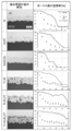
- a perspective view showing a test method of a tensile test for examining the strength of a porous film and (b) a porous film formed for the tensile test. It is an optical micrograph of a cross section. 6 is a graph showing the relationship between the thickness of the porous film and the tensile strength obtained by the tensile test shown in FIG. 11A.
- the distribution of the void ratio of the porous film when the gas pressure of the compressed gas at the time of injecting the metal powder by the cold spray method is (a) 312 kPa, and (b) porous.
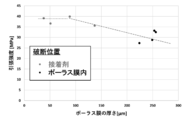
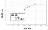
- FIG. 5 is a graph showing the relationship between the gas pressure of the compressed gas and the tensile strength of the porous film at the time of injecting the metal powder by the cold spray method, which was obtained by the tensile test shown in FIG. 11 (a).
- FIG. 1 to 14 show a method for manufacturing a composite member and a composite member according to the embodiment of the present invention.
- a metal porous film 12 is formed on the surface of the metal member 11.
- the porous film 12 may be formed by any method, but in a specific example shown in FIG. 1, a metal powder is made to collide with the surface of the metal member 11 by a cold spray method to form the porous film 12. ing.
- the metal member 11 is plate-shaped, and it is preferable to form a porous film 12 on one surface.
- the metal member 11 and the porous film 12 may be made of the same metal or may be made of different metals.
- the metal member 11 may be made of any metal, for example, aluminum or an aluminum alloy.
- the porous film 12 may also be made of any metal.
- titanium powder or titanium alloy powder may be used as the metal powder, and a strong porous film 12 made of titanium or a titanium alloy may be formed by a cold spray method.
- the metal member 11 and the resin-containing member 13 are joined by heating the metal member 11 in a state where the resin-containing member 13 is pressed against the porous film 12.
- the resin-containing member 13 may be made of any material depending on the required characteristics and applications. Further, the resin-containing member 13 may be made of only resin, or may be partially made of resin.
- the resin-containing member 13 may be made of a thermoplastic resin material such as PEEK (polyetheretherketone) or PA6 (polyamide 6) having high strength, and has a fibrous reinforcing material such as prepreg and a resin. It may consist of a thermosetting member.
- the method of heating the metal member 11 may be any method.
- a method of heating the metal member 11 with a heater or the like while the resin-containing member 13 is pressed against the metal member 11 may be used.
- a metal opposite to the porous film 12 is used by friction stir welding (FSW).
- FSW friction stir welding
- a method may be used in which the columnar joining tool 21 applied to the surface of the member 11 is pressed while rotating, and the metal member 11 is heated by frictional heat.
- the friction stir welding joining tool 21 generally has a shape in which a projecting probe 21b is provided at the center of a cylindrical shoulder 21a, but the deformation of the metal member 11 is suppressed and the joining interface is formed. It is preferable that the probe 21b is made of an extremely small protrusion so as to be as flat as possible.
- the resin-containing member 13 By heating the metal member 11 in this way, the resin-containing member 13 can be melted or softened and entered into the voids of the porous film 12. Thereby, the composite member according to the embodiment of the present invention in which the metal member 11 and the resin-containing member 13 are joined can be manufactured.
- the resin-containing member 13 contains a thermoplastic resin material, the resin-containing member 13 is not melted by heating at a temperature lower than the melting point of the resin-containing member 13. It can be joined and the composite member can be manufactured relatively easily.
- the method for producing a composite member according to the embodiment of the present invention by using the cold spray method, there is almost no oxidation or decomposition of the metal powder as a raw material, and the pores are in a state where the metal powders are well bonded to each other.
- the porous film 12 containing a large amount of the above can be formed. Since the voids of the porous film 12 are not oriented in one direction like the holes formed by laser irradiation, the resin-containing member 13 is not easily peeled off, and a composite member having high bonding strength can be manufactured. ..
- the porous film 12 by forming the porous film 12 by using the cold spray method, an expensive device is not required as in the case of using laser irradiation, and the composite member can be manufactured at low cost. Further, by the cold spray method, the porous film 12 can be formed on a wide area surface in a short time, and unlike the case where the chemical etching treatment is used, it is not necessary to perform a cleaning treatment or a waste liquid treatment, so that the time is short. The composite member can be efficiently manufactured in time.
- a metal member is used by friction stir welding (FSW). 11 and the resin-containing member 13 were joined.
- FSW friction stir welding
- the metal member 11 a rolled material of A5052 aluminum alloy was used.
- the metal member 11 has a rectangular plate shape that is long in the rolling direction, and has a length of 200 mm, a width of 50 mm, and a thickness of 5 mm.
- the metal member 11 is formed by applying alumina powder (particle size ⁇ 600 to 700 ⁇ m (# 40), ⁇ 200 to 250 ⁇ m (# 60), ⁇ 90 to 120 ⁇ m (# 120)) on one surface (joining surface) at a pressure of 0.3 MPa. The surface is roughened by injecting.
- alumina powder particle size ⁇ 600 to 700 ⁇ m (# 40), ⁇ 200 to 250 ⁇ m (# 60), ⁇ 90 to 120 ⁇ m (# 120)
- the surface is roughened by injecting.
- PEEK which is a thermoplastic resin material
- the resin-containing member 13 has a rectangular plate shape, a length of 200 mm, a width of 50 mm, and a thickness of 5 mm.
- a low-pressure cold spray device (“KM-CDS 3.0” manufactured by INOVATI) was used to form the porous film 12 by the cold spray method.
- the metal powder shown in Table 1 was used. Table 1 shows the film forming conditions for each metal powder [presence or absence of pretreatment (Blast), powder supply rate (Powder feed rate), compressed gas pressure (Gas pressure), process gas temperature (Gas temp.), The scanning speed of the spray nozzle (Traverse speed)] is also shown.
- a blast treatment using alumina particles (# 24) is performed on the joint surface of the metal member 11 after the roughening treatment. He gas is used as the process gas. Further, as shown in Table 1, the Traverse speed is changed in order to control the porosity and the thickness of the porous film 12. Further, in order to enhance the adhesion between the metal member 11 and the porous film 12, some heat treatments are performed after the film formation. The heat treatment was performed in an air atmosphere using an electric muffle furnace. The heat treatment temperature and holding time are 500 ° C and 30 min for Al powder and 600 ° C for Ti-20, Ti-45, Ti-20 + Ti-45 and Ti-20 + Al 2 O 3 powder. , 4 h (Ti-20 only, some 600 ° C, 2 h or 14 h), all of which were air-cooled.
- a high-rigidity friction stir welding device (“TU-01” manufactured by Nitto Seiki Co., Ltd.) was used to join the metal member 11 and the resin-containing member 13.
- the overlapping width of the metal member 11 and the resin-containing member 13 was 20 mm, and a joining tool 21 made of SKD61 was used.
- the joining tool 21 has a shape in which a probe 21b having a diameter of 5 mm protrudes 1.4 mm from the center of a columnar shoulder 21a having a tool diameter of 15 mm.
- the scanning speed of the joining tool 21 at the time of joining is 10.0 mm / s
- the rotation speed of the joining tool 21 is 1200 rpm
- the insertion depth of the joining tool 21 into the metal member 11 is 1.1 mm
- the advance angle of the joining tool 21 is 3 It was set to °.
- Optical micrographs are shown on the left side of FIGS. 2 to 4 for each metal powder and porous film 12 film formation conditions.
- the porous film 12 that has been heat-treated after being formed is indicated by "HT”.
- the porous film 12 that has not been blasted before being formed is indicated by "BL (Blastless)".
- the porosity of each porous film 12 and the porosity of the resin-containing member 13 permeated were measured by a point calculation method, and the permeation rate of the resin-containing member 13 was measured from each void ratio. (Filling rate) was calculated.
- the results are shown in the right figures of FIGS. 2 to 4, respectively.
- the horizontal axis of each figure is the ratio of the depth of the porous film 12 from the surface of the resin-containing member 13 side, 0% is the interface between the porous film 12 and the resin-containing member 13, and 100% is the porous film 12 and the metal. It is an interface with the member 11.
- the average value of the thickness and the porosity of each porous film 12 was obtained from each optical micrograph, and is shown in Table 2.
- the resin-containing member 13 has penetrated into the voids existing inside the porous membrane 12 to some extent, and the porous membrane 12 has a small porosity, for example, SUS316L. It was also confirmed that the resin-containing member 13 had penetrated. Further, it was confirmed that the permeation rate gradually decreased as the distance from the surface of the porous film 12 on the resin-containing member 13 side increased. From this, it is considered that there is a certain limit to the penetration depth of the resin-containing member 13.
- a rolled A5052 aluminum alloy material (no roughening treatment or pretreatment) was used as the metal member 11, and the metal member 11 and the resin were contained by friction stir welding without forming the porous film 12.
- Joining with the member (PEEK) 13 As a result, it was confirmed that the resin-containing member 13 was peeled off from the metal member 11 immediately after joining, and it was almost impossible to join.
- the surface of the rolled material of A5052 aluminum alloy is blasted with alumina particles (# 24, # 60, # 120) as the metal member 11, and the porous film 12 is formed.
- the metal member 11 and the resin-containing member (PEEK) 13 were joined by friction stir welding to manufacture a composite member.
- An optical micrograph of a cross section of the composite member near the bonding interface is shown in FIG.
- the resin-containing member 13 has penetrated into the fine uneven structure on the surface of the metal member 11 formed by the blast treatment, and the metal member 11 and the resin-containing member 13 are in close contact with each other without a gap. It was confirmed that it was done.
- a tensile shear test was performed on each of the manufactured composite members.
- the test was carried out at a crosshead speed of 1.0 mm / min at room temperature using a universal testing machine (manufactured by INSTRON).
- a universal testing machine manufactured by INSTRON
- strip-shaped test pieces with a width of 20 to 25 mm cut out from each composite member perpendicular to the joining direction were used.
- three test pieces were cut out from each composite material, each was subjected to a tensile shear test, and the values obtained by dividing each breaking load obtained by the joint area were averaged to obtain the tensile shear strength of each composite material.
- Table 3 shows the obtained tensile shear strength of each composite material.
- the porous film 12 was made of Al, Ti-20, Ti-45, Ti-20 + Ti-45, and Ti-20 + Al 2 O 3 powders. It was confirmed that the formed product was broken at the interface between the metal member 11 and the porous film 12. Further, it was confirmed that the one subjected to the heat treatment using the Ti-45 powder was broken in the porous film 12. Further, it was confirmed that the ones subjected to heat treatment using powders other than Ti-45 powder and those using SUS316L powder were broken at the interface between the porous film 12 and the resin-containing member 13.
- the relationship between the porosity of the porous film 12 and the tensile shear strength of the composite member fractured at the interface between the porous film 12 and the resin-containing member 13 during the tensile shear test was determined and shown in FIG. As shown in FIG. 6, it was confirmed that the tensile shear strength gradually increased as the porosity increased. Further, it was confirmed that even when the porosity was about 6.8%, the tensile shear strength was about 12 MPa, and the strength was sufficiently high.
- the porous film 12 is formed at various scanning speeds (Travers speed; ts) using Ti-20 powder, and heat treatment is performed after the film formation.
- the tensile shear strength was measured for the composite member. The measurement is performed on the composite member using the metal member 11 which has been subjected to the pretreatment blast treatment and the composite member using the metal member 11 which has not been subjected to the blast treatment. Further, the film thickness of the porous film 12 is changed by changing the scanning speed.
- FIG. 7 shows an optical micrograph of a cross section of the measured composite member near the bonding interface and the film thickness of the porous film 12. The relationship between the film thickness of the porous film 12 and the tensile shear strength is shown in FIG.
- the tensile shear strength increases as the film thickness of the porous film 12 increases, but it saturates to a certain strength with a certain film thickness. Further, it was confirmed that even when the film thickness of the porous film 12 was 38 ⁇ m, it had a tensile shear strength of 12 MPa or more, and had a sufficiently high strength.
- Ti-20 + Ti-45 powder was used to apply the porous film 12 at various scanning speeds.
- the tensile shear strength of the composite member formed and heat-treated after the film formation was measured in the same manner as in FIGS. 7 and 8.
- the relationship between the film thickness of the porous film 12 and the tensile shear strength is shown in FIG.
- the porous film 12 formed by using Ti-20 + Ti-45 powder has a larger porosity than that using Ti-20 powder.
- Non-Patent Document 4 a large number of pores are formed on the surface of the metal member 11 by laser irradiation, and the surface of the metal member 11 is filled with molten resin by hot pressing to cool and solidify the resin.
- a composite member was manufactured.
- a Ti alloy was used as the metal member 11, and PEEK was used as the resin.
- the diameter of the pores obtained by laser irradiation was about 270 ⁇ m, and the temperature of the hot press was 300 ° C.
- Optical micrographs of the cross section near the bonding interface of the composite member when the area ratios of the pores on the surface of the metal member 11 are 40% and 70% are shown in FIGS. 10 (b) and 10 (c), respectively.
- FIG. 10 (a) an optical micrograph of a cross section of a composite member manufactured by using a metal member 11 whose surface has been blasted using alumina particles (diameter 250 ⁇ m) without laser irradiation, in the vicinity of the bonding interface.
- FIG. 10 (a) As shown in FIGS. 10 (a) to 10 (c), in each of the composite members, the resin has penetrated into the irregularities and pores on the surface of the metal member 11, and the metal member 11 and the resin are in close contact with each other without any gaps. It was confirmed that Further, as shown in FIGS. 10 (b) and 10 (c), it was confirmed that the pores formed by laser irradiation extend only in the direction perpendicular to the surface of the metal member 11.
- the composite members shown in FIGS. 10A to 10C were subjected to a tensile shear test in the same manner as in Example 1.
- the tensile shear strength was 11 MPa for the blasted product shown in FIG. 10 (a), 25 MPa for the blasted product shown in FIG. 10 (b), and 25 MPa for the laser irradiation pore area ratio shown in FIG. 10 (b).
- the area ratio of the pores by laser irradiation shown in c) was 70%, which was 51 MPa. Comparing this result with the result shown in Table 3, it can be seen that the composite member using laser irradiation has a higher tensile shear strength than the one in which the porous film 12 is formed by the cold spray method.
- the composite member using the laser irradiation can be used. It is considered that the resin is less likely to be caught in the direction perpendicular to the surface of the metal member 11 and is more vulnerable to peeling than the porous film 12 formed by the cold spray method.
- the metal member 11 and the resin-containing member 13 were joined by friction stir welding (FSW).
- FSW friction stir welding
- Ti powder was used.
- the scanning speed of the joining tool 21 was 13 mm / s
- the rotation speed of the joining tool 21 was 1000 rpm
- the insertion depth of the joining tool 21 into the metal member 11 was 1.0 mm.
- Other production conditions were the same as in Example 1.
- a tensile shear test was performed on the manufactured composite member in the same manner as in Example 1. As a result, it was confirmed that the tensile shear strength was 10 MPa, which was higher than that of the composite member without the porous film 12 shown in FIG. The thickness of the produced porous film 12 of the composite member was about 130 ⁇ m.
- Example 2 A tensile shear test was performed on the manufactured composite member in the same manner as in Example 1. As a result, the tensile shear strength was 7 MPa or more. The thickness of the produced porous film 12 of the composite member was about 270 ⁇ m.
- the porous film 12 is formed by a cold spray method according to the method for manufacturing a composite member according to the embodiment of the present invention, and then a tensile test is performed on the porous film 12.
- a tensile test is performed on the porous film 12.
- FIG. 11A in the tensile test, A5052 aluminum alloy was used as the metal member 11.
- the metal member 11 has a cylindrical shape, has a diameter of 25 mm, and has a length of 40 mm.
- the formation and tensile test of the porous film 12 were carried out in the same manner as in Example 4.
- the porous films 12 having different porosities were formed by changing the gas pressure of the compressed gas at the time of injecting the metal powder to 312 kPa, 483 kPa, and 620 kPa.
- FIG. 13 shows the relationship between the distance of the porous film 12 from the surface of the metal member 11 and the porosity at each gas pressure, and a scanning electron micrograph of a cross section of the porous film 12.
- the porosity of the porous film 12 is about 4% to about 9%, and when the average is 5.58% and 483 kPa, the porosity of the porous film 12 is about 8%.
- the porosity of the porous film 12 is about 16% to about 16% and the average is 12.4% and 620 kPa, the porosity of the porous film 12 is about 6% to about 20% and the average is 13.5%. It was confirmed that the porosity of 12 was high.
- FIG. 14 shows the results of the tensile test for each porous film 12 having a different gas pressure.
- the gas pressures were 483 kPa and 620 kPa, the adhesive broke inside and the tensile strength was 40 MPa or more. Further, when the gas pressure was 312 kPa, it broke inside the porous film 12, and it was confirmed that the tensile strength was about 32 MPa.
- Metal member 12 Porous film 13 Resin-containing member 21 Joining Tool 21a Shoulder 21b Probe 31 Adhesive 32 Base material
Landscapes
- Engineering & Computer Science (AREA)
- Mechanical Engineering (AREA)
- Chemical & Material Sciences (AREA)
- Health & Medical Sciences (AREA)
- Toxicology (AREA)
- Chemical Kinetics & Catalysis (AREA)
- Materials Engineering (AREA)
- Metallurgy (AREA)
- Organic Chemistry (AREA)
- Laminated Bodies (AREA)
- Powder Metallurgy (AREA)
Abstract
【課題】安価で効率良く、接合強度の高い複合部材を製造することができる複合部材の製造方法および複合部材を提供する。 【解決手段】金属部材11の表面に形成された金属製のポーラス膜12に、樹脂含有部材13を押しつけた状態で、金属部材11を加熱することにより、金属部材11と樹脂含有部材13とを接合する。金属粉末をコールドスプレー法により金属部材11の表面に衝突させて、ポーラス膜12を形成することが好ましい。
Description
本発明は、複合部材の製造方法および複合部材に関する。
金属と樹脂とを接合する方法として、近年、樹脂を溶融させて金属表面と融着させる直接接合方法が盛んに研究されている(例えば、非特許文献1参照)。このような直接接合方法として、例えば、金属の表面に、化学エッチング処理による微細な孔食やレーザ照射による凹凸パターンの形成を行った後、その微細な構造にホットプレスや射出成型を用いて溶融樹脂を充填し、樹脂を冷却、固化させることにより、アンカー効果で強固に接合された複合部材を製造する方法が提案されている(例えば、特許文献1、非特許文献2乃至4参照)。
堀内伸、「樹脂-金属異種材料複合体接合特性の評価試験方法の国際基準」、制御と計測、2015年、54、p.743-747
瀬戸雅宏、朝見芳弘、板倉雅彦、田中宏明、山部昌、「樹脂-金属接合射出成形品の接合強さに与える成形条件の影響」、成形加工、2015年、27、p.68-74
堀内伸、花田剛、宮前孝行、山中忠衛、大隅光悟朗、安藤直樹、成富正徳、「エネルギーフィルター透過型電子顕微鏡法による金属/樹脂接合界面の解析」、日本接着学会誌、2012年、48、p.322-330
B. Henriques, "Laser surface structuring of Ti6Al4V substrates for adhesion enhancement in Ti6Al4V-PEEK joints", Materials Science and Engineering: C, 2017, 79, p.177-184
しかしながら、特許文献1や非特許文献2乃至4に記載の直接接合による複合部材の製造方法では、レーザ照射を利用した場合には、レーザ照射により形成した穴に垂直な方向での引っかかりが弱く、樹脂が剥がれやすいという課題があった。また、レーザ照射の制御において扱うパラメータの数が多く、製造工程が煩雑であり、装置も高価であるという課題もあった。また、化学エッチング処理を利用した場合には、腐食溶液に浸漬する際に金属表面の洗浄・脱脂などの事前清浄化を複数サイクル繰り返す必要があり、また、化学溶液を用いることによる洗浄処理および廃液処理も必要であるため、製造効率が悪いという課題があった。
本発明は、このような課題に着目してなされたもので、安価で効率良く、接合強度の高い複合部材を製造することができる複合部材の製造方法および複合部材を提供することを目的とする。
上記目的を達成するために、本発明に係る複合部材の製造方法は、金属部材の表面に形成された金属製のポーラス膜に、樹脂含有部材を押しつけた状態で、前記金属部材を加熱することにより、前記金属部材と前記樹脂含有部材とを接合することを特徴とする。
本発明に係る複合部材は、金属部材と、前記金属部材の表面に形成されたポーラス膜と、前記ポーラス膜の前記金属部材とは反対側に設けられた樹脂含有部材とを有し、前記樹脂含有部材の一部が前記ポーラス膜の空隙に入り込むことにより、前記金属部材と前記樹脂含有部材とが接合されていることを特徴とする。
本発明に係る複合部材の製造方法は、本発明に係る複合部材を好適に製造することができる。本発明に係る複合部材の製造方法は、金属部材を加熱することにより、樹脂含有部材を溶融または軟化させて、ポーラス膜の空隙に入り込ませることができる。このとき、ポーラス膜の空隙が、レーザ照射で形成した穴のように一つの方向に向いているものではないため、樹脂含有部材が容易に剥がれず、接合強度の高い複合部材を製造することができる。
本発明に係る複合部材の製造方法は、いかなる方法でポーラス膜を形成してもよいが、特に、金属粉末をコールドスプレー法により前記金属部材の表面に衝突させて、前記ポーラス膜を形成することが好ましい。コールドスプレー法を利用することにより、原料の金属粉末の酸化や分解がほとんどなく、金属粉末同士が良好に接合された状態で、気孔を多く含んだポーラス膜を形成することができる。コールドスプレー法を利用してポーラス膜を形成することにより、レーザ照射を利用する場合のように高価な装置が不要であり、安価に複合部材を製造することができる。また、コールドスプレー法により、広範囲面に対して短時間でポーラス膜を形成することができ、化学エッチング処理を利用する場合のように、洗浄処理や廃液処理などを行う必要がないため、短時間で効率良く複合部材を製造することができる。
本発明に係る複合部材の製造方法および複合部材で、前記金属部材と前記ポーラス膜とは、同じ金属から成っていてもよく、異なる金属から成っていてもよい。金属部材は、いかなる金属から成っていてもよく、例えば、アルミニウムやアルミニウム合金から成っていてもよい。ポーラス膜は、アルミニウム、アルミニウム合金、ステンレス鋼、チタン、チタン合金等、いかなる金属から成っていてもよいが、コールドスプレー法により形成するのであれば、チタンまたはチタン合金から成っていることが好ましい。この場合、金属粉末としてチタン粉末またはチタン合金を使用して、強固なポーラス膜を形成することができる。
本発明に係る複合部材の製造方法は、前記樹脂含有部材を前記ポーラス膜に接触させた状態で、前記金属部材を前記樹脂含有部材に向かって押しつけつつ、前記金属部材を摩擦して加熱してもよい。この場合、例えば、摩擦攪拌接合(FSW)を利用して、ポーラス膜とは反対側から、金属部材の表面に当てた円柱状の接合ツールを回転させながら押しつけることにより、金属部材と樹脂含有部材とを接合することができる。
本発明に係る複合部材の製造方法および複合部材で、前記樹脂含有部材は、要求される特性や用途に応じていかなるものから成っていてもよく、例えば、熱可塑性樹脂材や、加熱硬化前の熱硬化性樹脂材を有していてもよい。また、樹脂含有部材は、樹脂のみから成っていてもよく、一部が樹脂であってもよい。樹脂含有部材が熱可塑性樹脂材を有する場合、その熱可塑性樹脂材の融点よりも低い温度で、金属部材を加熱することが好ましい。この場合、樹脂含有部材を溶融させずに接合することができ、比較的容易に複合部材を製造することができる。また、熱可塑性樹脂材としては、例えば、強度の高いPEEK(ポリエーテルエーテルケトン)またはPA6(ポリアミド6)等である。樹脂含有部材が加熱硬化前の熱硬化性樹脂材を有する場合、その熱硬化性樹脂材の融点よりも高い温度で、金属部材を加熱することが好ましい。この場合、樹脂含有部材は、例えばプリプレグなど、繊維状の強化材と樹脂とを有する熱硬化性の部材から成っていてもよい。
本発明に係る複合部材の製造方法および複合部材で、前記ポーラス膜は、空隙率が4%以上であることが好ましく、30%以下であることが好ましい。また、前記ポーラス膜は、膜厚が25μm以上であることが好ましく、280μm以下であることが好ましい。これらの場合、金属部材と樹脂含有部材との接合部の強度が高く、接合した金属部材と樹脂含有部材とが分離しにくい。さらに、ポーラス膜は、空隙率が6%以上であることが好ましく、さらに27%以下であることが好ましい。また、ポーラス膜は、膜厚が35μm以上であることが好ましく、150μm以下であることが好ましい。これらの場合、ポーラス膜の強度がさらに高くなるため、接合した金属部材と樹脂含有部材とが特に分離しにくい。
本発明によれば、安価で効率良く、接合強度の高い複合部材を製造することができる複合部材の製造方法および複合部材を提供することができる。
以下、図面および実施例等に基づいて、本発明の実施の形態について説明する。
図1乃至図14は、本発明の実施の形態の複合部材の製造方法および複合部材を示している。
図1に示すように、本発明の実施の形態の複合部材の製造方法は、まず、金属部材11の表面に金属製のポーラス膜12を形成する。このとき、いかなる方法でポーラス膜12を形成してもよいが、図1に示す具体的な一例では、金属粉末をコールドスプレー法により金属部材11の表面に衝突させて、ポーラス膜12を形成している。金属部材11は、板状であり、一方の表面にポーラス膜12を形成することが好ましい。
図1乃至図14は、本発明の実施の形態の複合部材の製造方法および複合部材を示している。
図1に示すように、本発明の実施の形態の複合部材の製造方法は、まず、金属部材11の表面に金属製のポーラス膜12を形成する。このとき、いかなる方法でポーラス膜12を形成してもよいが、図1に示す具体的な一例では、金属粉末をコールドスプレー法により金属部材11の表面に衝突させて、ポーラス膜12を形成している。金属部材11は、板状であり、一方の表面にポーラス膜12を形成することが好ましい。
金属部材11とポーラス膜12とは、同じ金属から成っていてもよく、異なる金属から成っていてもよい。金属部材11は、いかなる金属から成っていてもよく、例えば、アルミニウムやアルミニウム合金から成っている。ポーラス膜12も、いかなる金属から成っていてもよい。例えば、金属粉末としてチタン粉末またはチタン合金粉末を使用し、コールドスプレー法により、チタンまたはチタン合金から成る強固なポーラス膜12を形成してもよい。
ポーラス膜12を形成後、樹脂含有部材13を押しつけた状態で、金属部材11を加熱することにより、金属部材11と樹脂含有部材13とを接合する。このとき、樹脂含有部材13は、要求される特性や用途に応じていかなるものから成っていてもよい。また、樹脂含有部材13は、樹脂のみから成っていてもよく、一部が樹脂であってもよい。樹脂含有部材13は、例えば、強度の高いPEEK(ポリエーテルエーテルケトン)またはPA6(ポリアミド6)等の熱可塑性樹脂材から成っていてもよく、プリプレグなど、繊維状の強化材と樹脂とを有する熱硬化性の部材から成っていてもよい。
金属部材11を加熱する方法は、いかなる方法であってもよく、例えば、図1(a)に示すように、樹脂含有部材13を押しつけた状態で、ヒーターなどで金属部材11を加熱する方法や、図1(b)および(c)に示すように、樹脂含有部材13をポーラス膜12に接触させた状態で、摩擦攪拌接合(FSW)を利用して、ポーラス膜12とは反対側の金属部材11の表面に当てた円柱状の接合ツール21を回転させながら押しつけ、摩擦熱により金属部材11を加熱する方法であってもよい。なお、摩擦攪拌接合の接合ツール21は、一般的に、円柱形状のショルダ21aの中央部に、突出したプローブ21bを有する形状を成しているが、金属部材11の変形を抑え、接合界面が可能なかぎり平坦になるよう、プローブ21bの突出量が極めて小さいものから成っていることが好ましい。
こうして金属部材11を加熱することにより、樹脂含有部材13を溶融または軟化させて、ポーラス膜12の空隙に入り込ませることができる。これにより、金属部材11と樹脂含有部材13とが接合された、本発明の実施の形態の複合部材を製造することができる。なお、金属部材11を加熱する際、樹脂含有部材13が熱可塑性樹脂材を含む場合には、樹脂含有部材13の融点よりも低い温度で加熱することにより、樹脂含有部材13を溶融させずに接合することができ、比較的容易に複合部材を製造することができる。
本発明の実施の形態の複合部材の製造方法によれば、コールドスプレー法を利用することにより、原料の金属粉末の酸化や分解がほとんどなく、金属粉末同士が良好に接合された状態で、気孔を多く含んだポーラス膜12を形成することができる。ポーラス膜12の空隙は、レーザ照射で形成した穴のように一つの方向に向いているものではないため、樹脂含有部材13が容易に剥がれず、接合強度の高い複合部材を製造することができる。
また、コールドスプレー法を利用してポーラス膜12を形成することにより、レーザ照射を利用する場合のように高価な装置が不要であり、安価に複合部材を製造することができる。また、コールドスプレー法により、広範囲面に対して短時間でポーラス膜12を形成することができ、化学エッチング処理を利用する場合のように、洗浄処理や廃液処理などを行う必要がないため、短時間で効率良く複合部材を製造することができる。
図1(b)および(c)に示す本発明の実施の形態の複合部材の製造方法により、コールドスプレー法でポーラス膜12を形成した後、摩擦攪拌接合(FSW)を利用して、金属部材11と樹脂含有部材13との接合を行った。金属部材11としては、A5052 アルミニウム合金の圧延材を用いた。金属部材11は、圧延方向に長い矩形板状であり、長さ200 mm、幅 50 mm、厚さ 5 mmである。また、金属部材11は、一方の表面(接合面)にアルミナ粉末(粒子径φ600~700μm(#40)、φ200~250μm(#60)、φ90~120μm(#120))を、圧力 0.3 MPa で噴射して、粗面化処理を行っている。樹脂含有部材13としては、熱可塑性樹脂材のPEEKを用いた。樹脂含有部材13は、矩形板状であり、長さ200 mm、幅 50 mm、厚さ 5 mmである。
コールドスプレー法によるポーラス膜12の形成には、低圧型コールドスプレー装置(INOVATI社製「KM-CDS 3.0」)を使用した。コールドスプレー法では、表1に示す金属粉末を使用した。表1には、金属粉末ごとに成膜条件[前処理(Blast)の有無、粉末の供給速度(Powder feed rate)、圧縮ガスの圧力(Gas pressure)、プロセスガスの温度(Gas temp.)、スプレーノズルの走査速度(Traverse speed)]も示している。

なお、前処理としては、粗面化処理後の金属部材11の接合面に対して、アルミナ粒子(#24)を用いたブラスト(Blast)処理を行っている。また、プロセスガスには Heガスを用いている。また、ポーラス膜12の空隙率と厚さとを制御するために、表1に示すように、Traverse speed を変化させている。また、金属部材11とポーラス膜12との密着力を高めるために、成膜後の熱処理を行ったものもある。熱処理は、電気マッフル炉を用いて、大気雰囲気で行った。熱処理温度および保持時間は、Al粉末の場合、500℃、30 minであり、Ti-20、Ti-45、Ti-20+Ti-45、Ti-20+Al2O3粉末の場合、600℃、4 h(Ti-20 のみ、一部で、600℃、2 h または 14 h)であり、いずれも空冷とした。
金属部材11と樹脂含有部材13との接合には、高剛性摩擦攪拌接合装置(日東制機(株)製「TU-01」)を用いた。金属部材11と樹脂含有部材13との重ね幅を20 mm とし、接合ツール21として、SKD61製のものを用いた。接合ツール21は、ツール直径15 mmの円柱状のショルダ21aの中心部に、直径5 mmのプローブ21bが1.4 mm突出した形状を成している。接合時の接合ツール21の走査速度を 10.0 mm/s、接合ツール21の回転速度を 1200 rpm、金属部材11への接合ツール21の挿入深さを 1.1 mmとし、接合ツール21の前進角を 3°とした。
表1に示す各金属粉末を用いてポーラス膜12を形成し、金属部材11(Al合金)と樹脂含有部材(PEEK)13とを接合して製造された複合部材の、接合界面付近の断面の光学顕微鏡写真を、各金属粉末およびポーラス膜12の成膜条件毎に、図2~4の左図に示す。なお、ポーラス膜12の成膜後に熱処理を行ったものを、「HT」で示す。また、ポーラス膜12の成膜前にブラスト処理を行っていないものを、「BL(Blast less)」で示す。
各光学顕微鏡写真から、各ポーラス膜12の空隙率(Porosity)と、樹脂含有部材13が浸透した空隙率(Filled by PEEK)を点算法で測定し、各空隙率から樹脂含有部材13の浸透率(Filling rate)を計算した。その結果を、それぞれ図2~4の右図に示す。各図の横軸は、ポーラス膜12の樹脂含有部材13側の表面からの深さの割合であり、0%がポーラス膜12と樹脂含有部材13との界面、100%がポーラス膜12と金属部材11との界面である。また、各光学顕微鏡写真から、各ポーラス膜12の厚みおよび空隙率の平均値を求め、表2に示す。

図2~4、表2に示すように、ポーラス膜12の内部に存在する空隙に、樹脂含有部材13がある程度浸透しており、例えばSUS316Lのように、空隙率が小さいポーラス膜12であっても、樹脂含有部材13が浸透していることが確認された。また、その浸透率は、ポーラス膜12の樹脂含有部材13側の表面からの距離が大きくなるに従って、徐々に減少することが確認された。このことから、樹脂含有部材13の浸透深さには、一定の限界が存在するものと考えられる。
なお、比較のために、金属部材11として、A5052 アルミニウム合金の圧延材(粗面化処理、前処理無し)を用い、ポーラス膜12を形成せずに、摩擦攪拌接合により金属部材11と樹脂含有部材(PEEK)13との接合を行った。その結果、接合後すぐに、樹脂含有部材13が金属部材11から剥離してしまい、ほとんど接合できないことが確認された。
さらに、比較のために、金属部材11として、A5052 アルミニウム合金の圧延材の表面を、アルミナ粒子(#24、#60、#120)を用いてブラスト処理したものを用い、ポーラス膜12を形成せずに、摩擦攪拌接合により金属部材11と樹脂含有部材(PEEK)13との接合を行って、複合部材を製造した。この複合部材の接合界面付近の断面の光学顕微鏡写真を、図5に示す。図5に示すように、ブラスト処理により形成された金属部材11の表面の微細な凹凸構造の内部に、樹脂含有部材13が浸透しており、金属部材11と樹脂含有部材13とが隙間なく密着していることが確認された。
次に、製造した各複合部材に対して、引張せん断試験を行った。試験は、万能試験機(INSTRON製)を用いて、室温下で、クロスヘッド速度1.0 mm/minで行った。試験には、各複合部材から接合方向に対して垂直に切り出した、幅 20~25 mmの短冊状の試験片を用いた。また、各複合材料から3つの試験片を切り出して、それぞれ引張せん断試験を行い、得られた各破断荷重を接合面積で割った値を平均して、各複合材料の引張せん断強度とした。求めた各複合材料の引張せん断強度を、表3に示す。

また、比較のため、図5に示すポーラス膜12がない複合部材に対しても、同様に引張せん断試験を行った。その結果、引張せん断強度が7.9~8.7MPaであり、金属部材11の表面が平滑になるに従って、強度が低下することが確認された。表3に示すように、ポーラス膜12を有する複合部材は、引張せん断強度が9.62~15.8MPaであり、ポーラス膜12がない複合部材よりも強度が高いことが確認された。
また、引張せん断試験後の破断面を観察したところ、Al、Ti-20、Ti-45、Ti-20+Ti-45、Ti-20+Al2O3の各粉末を使用してポーラス膜12を形成したものは、金属部材11とポーラス膜12との界面で破断していることが確認された。また、Ti-45粉末を使用し、熱処理を行ったものは、ポーラス膜12の中で破断していることが確認された。また、Ti-45粉末以外の粉末を使用し、熱処理を行ったものやSUS316L粉末を使用したものは、ポーラス膜12と樹脂含有部材13との界面で破断していることが確認された。
引張せん断試験の際に、ポーラス膜12と樹脂含有部材13との界面で破断した複合部材について、ポーラス膜12の空隙率と引張せん断強度との関係を求め、図6に示す。図6に示すように、空隙率が高くなるに従って、引張せん断強度が徐々に高くなることが確認された。また、空隙率が6.8%程度でも、12MPa程度の引張せん断強度を有しており、十分に高い強度を有していることが確認された。
次に、ポーラス膜12の膜厚と強度との関係を調べるため、Ti-20粉末を使用して、様々な走査速度(Travers speed;ts)でポーラス膜12を形成し、成膜後に熱処理を行った複合部材に対して、引張せん断強度を測定した。なお、測定は、前処理のブラスト処理を行った金属部材11を使用した複合部材、および、ブラスト処理を行っていない金属部材11を使用した複合部材に対して行っている。また、走査速度を変えることにより、ポーラス膜12の膜厚を変化させている。測定を行った複合部材の接合界面付近の断面の光学顕微鏡写真およびポーラス膜12の膜厚を、図7に示す。また、ポーラス膜12の膜厚と引張せん断強度との関係を、図8に示す。
図7および図8に示すように、ポーラス膜12の膜厚が大きくなるに従って、引張せん断強度は高くなるが、ある程度の膜厚で一定の強度に飽和することが確認された。また、ポーラス膜12の膜厚が38μmでも、12MPa以上の引張せん断強度を有しており、十分に高い強度を有していることが確認された。
ポーラス膜12の空隙率の違いが、ポーラス膜12の膜厚と強度との関係に与える影響を調べるため、Ti-20+Ti-45粉末を使用して、様々な走査速度でポーラス膜12を形成し、成膜後に熱処理を行った複合部材に対して、図7および図8と同様に、引張せん断強度を測定した。ポーラス膜12の膜厚と引張せん断強度との関係を、図9に示す。なお、Ti-20+Ti-45粉末を使用して形成したポーラス膜12は、Ti-20粉末を使用したものよりも空隙率が大きい。
図9に示すように、図8と同様に、ポーラス膜12の膜厚が大きくなるに従って、引張せん断強度が高くなり、ある程度の膜厚で一定の強度に飽和することが確認された。しかし、図8と比べて、飽和する強度が高く、飽和強度となるときの膜厚も大きいことが確認された。これは、空隙率が高くなるに従って、樹脂含有部材13のせん断強度が確保されるためであると考えられる。
[レーザ照射を利用した比較例]
非特許文献4に記載のように、レーザ照射により金属部材11の表面に多数の細孔を形成し、ホットプレスにより、金属部材11の表面に溶融樹脂を充填し、樹脂を冷却、固化させて複合部材を製造した。金属部材11として、Ti合金を用い、樹脂として、PEEKを用いた。また、レーザ照射による細孔の径は、約270μm、ホットプレスの温度は、300℃とした。金属部材11の表面での細孔の面積率を40%および70%としたときの、複合部材の接合界面付近の断面の光学顕微鏡写真を、それぞれ図10(b)および(c)に示す。
非特許文献4に記載のように、レーザ照射により金属部材11の表面に多数の細孔を形成し、ホットプレスにより、金属部材11の表面に溶融樹脂を充填し、樹脂を冷却、固化させて複合部材を製造した。金属部材11として、Ti合金を用い、樹脂として、PEEKを用いた。また、レーザ照射による細孔の径は、約270μm、ホットプレスの温度は、300℃とした。金属部材11の表面での細孔の面積率を40%および70%としたときの、複合部材の接合界面付近の断面の光学顕微鏡写真を、それぞれ図10(b)および(c)に示す。
なお、比較のため、金属部材11として、レーザ照射を行わず、アルミナ粒子(径250μm)を用いて表面をブラスト処理したものを用いて製造した複合部材の、接合界面付近の断面の光学顕微鏡写真を、図10(a)に示す。図10(a)~(c)に示すように、いずれの複合部材も、金属部材11の表面の凹凸や細孔の内部に樹脂が浸透しており、金属部材11と樹脂が隙間なく密着していることが確認された。また、図10(b)および(c)に示すように、レーザ照射により形成した細孔は、金属部材11の表面に対して垂直方向にのみ伸びていることが確認された。
図10(a)~(c)に示す複合部材に対して、実施例1と同様にして、引張せん断試験を行った。その結果、引張せん断強度は、図10(a)に示すブラスト処理のものが、11MPa、図10(b)に示すレーザ照射による細孔の面積率が40%のものが、25MPa、図10(c)に示すレーザ照射による細孔の面積率が70%のものが、51MPaであった。この結果を、表3に示す結果と比較すると、レーザ照射を利用した複合部材の方が、コールドスプレー法によりポーラス膜12を形成したものよりも、引張せん断強度が大きいことがわかる。しかし、図10(b)および(c)に示すように、レーザ照射により形成した孔は、金属部材11の表面に対して垂直方向にのみ伸びているため、レーザ照射を利用した複合部材は、金属部材11の表面に垂直な方向での樹脂の引っかかりが弱く、コールドスプレー法によりポーラス膜12を形成したものよりも、剥離には弱いと考えられる。
金属部材11として、A5052 アルミニウム合金の圧延材を用い、樹脂含有部材13として、熱可塑性樹脂材のPA6を用いて、図1(b)および(c)に示す本発明の実施の形態の複合部材の製造方法により、コールドスプレー法でポーラス膜12を形成した後、摩擦攪拌接合(FSW)を利用して、金属部材11と樹脂含有部材13との接合を行った。コールドスプレー法では、Ti粉末を用いた。摩擦攪拌接合では、接合ツール21の走査速度を 13 mm/s、接合ツール21の回転速度を 1000 rpm、金属部材11への接合ツール21の挿入深さを 1.0 mmとした。他の製造条件は、実施例1と同様とした。
製造された複合部材に対し、実施例1と同様にして、引張せん断試験を行った。その結果、引張せん断強度は10MPaであり、図5に示すポーラス膜12がない複合部材よりも、引張せん断強度が高いことが確認された。なお、製造された複合部材のポーラス膜12は、膜厚が約130μmであった。
金属部材11として、A5052 アルミニウム合金の圧延材を用い、樹脂含有部材13として、PA6を用いて、図1(a)に示す本発明の実施の形態の複合部材の製造方法により、コールドスプレー法でポーラス膜12を形成した後、樹脂含有部材13を押しつけた状態で、ヒーターで金属部材11を加熱して、金属部材11と樹脂含有部材13との接合を行った。金属部材11に対して樹脂含有部材13をハンドプレスで押しつけ、金属部材11の加熱温度は300℃とした。
製造された複合部材に対し、実施例1と同様にして、引張せん断試験を行った。その結果、引張せん断強度は7MPa以上であった。なお、製造された複合部材のポーラス膜12は、膜厚が約270μmであった。
ポーラス膜12の厚さと強度との関係を調べるために、本発明の実施の形態の複合部材の製造方法により、コールドスプレー法でポーラス膜12を形成した後、そのポーラス膜12に対して引張試験を行った。図11(a)に示すように、引張試験では、金属部材11として、A5052 アルミニウム合金を用いた。金属部材11は、円柱形状であり、直径25 mm、長さ40 mmである。コールドスプレー法では、粒子径が1~45μmのTi-45粉末を使用し、圧縮ガスの圧力を 620 kPa、プロセスガスの温度を 427 ℃、スプレーノズルの走査速度を 500 mm/s とした。また、コールドスプレー法での積層数を変えることにより、様々な厚さのポーラス膜12を形成した。ポーラス膜12の空隙率は、全て6%以上である。金属部材11の一方の表面に形成したポーラス膜12の断面の光学顕微鏡写真の一例を、図11(b)に示す。
図11(a)に示すように、引張試験では、形成した各ポーラス膜12の表面に接着剤(Adhesive)31を塗布した後、金属部材11と同じ大きさのA5052 アルミニウム合金製の基材32を接着した。接着剤31には、「3M(登録商標) Scotch-Weld(登録商標) DP-460 Off-White(スリーエムジャパン株式会社)」を用いた。接着剤で接着後、金属部材11と基材32とを引っ張って、各ポーラス膜12に対する引張強度を求めた。引張試験の結果を、図12に示す。
図12に示すように、引張試験の結果、ポーラス膜12の厚さが150μm以下のときには、接着剤の内部で破断し、引張強度が35MPa以上であることが確認された。また、ポーラス膜12の厚さが150μm以上のときには、金属部材11に近いポーラス膜12の内部で破断し、引張強度が35MPa以下であることが確認された。この結果から、ポーラス膜12を150μm以下にすることにより、ポーラス膜の強度が少なくとも35MPa以上となり、複合部材を製造したとき、接合した金属部材11と樹脂含有部材13とが分離しにくくなるといえる。
ポーラス膜12の空隙率と強度との関係を調べるために、実施例4と同様にして、ポーラス膜12の形成および引張試験を行った。コールドスプレー法では、金属粉末噴射時の圧縮ガスのガス圧を312kPa、483kPa、620kPaと変えることにより、空隙率が異なるポーラス膜12を形成した。各ガス圧での、ポーラス膜12の金属部材11の表面からの距離と空隙率との関係、およびポーラス膜12の断面の走査型電子顕微鏡写真を、図13に示す。
図13に示すように、ガス圧が312kPaのとき、ポーラス膜12の空隙率は約4%~約9%で、平均5.58%、483kPaのとき、ポーラス膜12の空隙率は約8%~約16%で、平均12.4%、620kPaのとき、ポーラス膜12の空隙率は約6%~約20%で、平均13.5%となっており、ガス圧が高いほど、ポーラス膜12の空隙率が高くなることが確認された。これは、ガス圧が低いときには、金属粉末の衝突力が小さいことから、粒子径が大きい粒子は接合せず、粒子径が小さい金属粉末のみが堆積して粒子間のすき間を埋め、ガス圧が高いときには、金属粉末の衝突力が大きくなることから、粒子径が大きい粒子が接合して、その粒子間にすき間が生じやすいためであると考えられる。
ガス圧が異なる各ポーラス膜12に対する引張試験の結果を、図14に示す。図14に示すように、引張試験の結果、ガス圧が483kPa、620kPaのときには、接着剤の内部で破断し、引張強度が40MPa以上であることが確認された。また、ガス圧が312kPaのときには、ポーラス膜12の内部で破断し、引張強度が約32MPaであることが確認された。この結果から、ガス圧を483kPa以上、すなわちポーラス膜12の空隙率を6%以上、平均の空隙率を12%以上にすることにより、ポーラス膜の強度が少なくとも40MPa以上となり、複合部材を製造したとき、接合した金属部材11と樹脂含有部材13とが分離しにくくなるといえる。
11 金属部材
12 ポーラス膜
13 樹脂含有部材
21 接合ツール
21a ショルダ
21b プローブ
31 接着剤
32 基材
12 ポーラス膜
13 樹脂含有部材
21 接合ツール
21a ショルダ
21b プローブ
31 接着剤
32 基材
Claims (14)
- 金属部材の表面に形成された金属製のポーラス膜に、樹脂含有部材を押しつけた状態で、前記金属部材を加熱することにより、前記金属部材と前記樹脂含有部材とを接合することを特徴とする複合部材の製造方法。
- 金属粉末をコールドスプレー法により前記金属部材の表面に衝突させて、前記ポーラス膜を形成することを特徴とする請求項1記載の複合部材の製造方法。
- 前記金属部材と前記ポーラス膜とは異なる金属から成ることを特徴とする請求項1または2記載の複合部材の製造方法。
- 前記樹脂含有部材を前記ポーラス膜に接触させた状態で、前記金属部材を前記樹脂含有部材に向かって押しつけつつ、前記金属部材を摩擦して加熱することを
特徴とする請求項1乃至3のいずれか1項に記載の複合部材の製造方法。 - 前記樹脂含有部材は熱可塑性樹脂材であることを特徴とする請求項1乃至4のいずれか1項に記載の複合部材の製造方法。
- 前記樹脂含有部材は、繊維状の強化材と樹脂とを有する熱硬化性の部材から成ることを特徴とする特徴とする請求項1乃至4のいずれか1項に記載の複合部材の製造方法。
- 前記ポーラス膜は、空隙率が4%以上であることを特徴とする請求項1乃至6のいずれか1項に記載の複合部材の製造方法。
- 前記ポーラス膜は、膜厚が25μm以上280μm以下であることを特徴とする請求項1乃至7のいずれか1項に記載の複合部材の製造方法。
- 金属部材と、
前記金属部材の表面に形成されたポーラス膜と、
前記ポーラス膜の前記金属部材とは反対側に設けられた樹脂含有部材とを有し、
前記樹脂含有部材の一部が前記ポーラス膜の空隙に入り込むことにより、前記金属部材と前記樹脂含有部材とが接合されていることを
特徴とする複合部材。 - 前記金属部材と前記ポーラス膜とは異なる金属から成ることを特徴とする請求項9記載の複合部材。
- 前記樹脂含有部材は熱可塑性樹脂材であることを特徴とする請求項9または10記載の複合部材。
- 前記樹脂含有部材は、繊維状の強化材と樹脂とを有する熱硬化性の部材から成ることを特徴とする特徴とする請求項9または10記載の複合部材。
- 前記ポーラス膜は、空隙率が4%以上であることを特徴とする請求項9乃至12のいずれか1項に記載の複合部材。
- 前記ポーラス膜は、膜厚が25μm以上280μm以下であることを特徴とする請求項9乃至13のいずれか1項に記載の複合部材。
Priority Applications (3)
| Application Number | Priority Date | Filing Date | Title |
|---|---|---|---|
| US17/912,966 US20230118556A1 (en) | 2020-03-25 | 2021-03-23 | Method for manufacturing composite member, and composite member |
| EP21776342.4A EP4129552A4 (en) | 2020-03-25 | 2021-03-23 | Method for manufacturing composite member, and composite member |
| CN202180021530.2A CN115279575A (zh) | 2020-03-25 | 2021-03-23 | 复合构件的制造方法及复合构件 |
Applications Claiming Priority (4)
| Application Number | Priority Date | Filing Date | Title |
|---|---|---|---|
| JP2020-053609 | 2020-03-25 | ||
| JP2020053609 | 2020-03-25 | ||
| JP2021048892A JP2021154733A (ja) | 2020-03-25 | 2021-03-23 | 複合部材の製造方法および複合部材 |
| JP2021-048892 | 2021-03-23 |
Publications (1)
| Publication Number | Publication Date |
|---|---|
| WO2021193643A1 true WO2021193643A1 (ja) | 2021-09-30 |
Family
ID=77892153
Family Applications (1)
| Application Number | Title | Priority Date | Filing Date |
|---|---|---|---|
| PCT/JP2021/012011 WO2021193643A1 (ja) | 2020-03-25 | 2021-03-23 | 複合部材の製造方法および複合部材 |
Country Status (2)
| Country | Link |
|---|---|
| US (1) | US20230118556A1 (ja) |
| WO (1) | WO2021193643A1 (ja) |
Citations (5)
| Publication number | Priority date | Publication date | Assignee | Title |
|---|---|---|---|---|
| JP2010046831A (ja) * | 2008-08-19 | 2010-03-04 | Toyota Motor Corp | 樹脂と金属との接合方法および装置 |
| WO2011145202A1 (ja) * | 2010-05-21 | 2011-11-24 | トヨタ自動車株式会社 | 半導体装置 |
| WO2014021184A1 (ja) * | 2012-07-30 | 2014-02-06 | コロナ工業株式会社 | マグネシウム材と樹脂部品の複合品及びその製造方法 |
| JP2019166638A (ja) * | 2018-03-21 | 2019-10-03 | 学校法人早稲田大学 | 樹脂金属接合体の製造方法及び樹脂金属接合体 |
| JP2019177704A (ja) | 2019-07-26 | 2019-10-17 | 株式会社大貫工業所 | 金属部品と樹脂の接合方法及び金属部品と樹脂の一体成形品 |
Family Cites Families (2)
| Publication number | Priority date | Publication date | Assignee | Title |
|---|---|---|---|---|
| US20070196681A1 (en) * | 2004-11-15 | 2007-08-23 | Taryn Biggs | Laminate panel and process for production thereof |
| US9440287B2 (en) * | 2014-08-15 | 2016-09-13 | Siemens Energy, Inc. | Coatings for high temperature components |
-
2021
- 2021-03-23 US US17/912,966 patent/US20230118556A1/en active Pending
- 2021-03-23 WO PCT/JP2021/012011 patent/WO2021193643A1/ja unknown
Patent Citations (5)
| Publication number | Priority date | Publication date | Assignee | Title |
|---|---|---|---|---|
| JP2010046831A (ja) * | 2008-08-19 | 2010-03-04 | Toyota Motor Corp | 樹脂と金属との接合方法および装置 |
| WO2011145202A1 (ja) * | 2010-05-21 | 2011-11-24 | トヨタ自動車株式会社 | 半導体装置 |
| WO2014021184A1 (ja) * | 2012-07-30 | 2014-02-06 | コロナ工業株式会社 | マグネシウム材と樹脂部品の複合品及びその製造方法 |
| JP2019166638A (ja) * | 2018-03-21 | 2019-10-03 | 学校法人早稲田大学 | 樹脂金属接合体の製造方法及び樹脂金属接合体 |
| JP2019177704A (ja) | 2019-07-26 | 2019-10-17 | 株式会社大貫工業所 | 金属部品と樹脂の接合方法及び金属部品と樹脂の一体成形品 |
Non-Patent Citations (4)
| Title |
|---|
| B. HENRIQUES: "Laser surface structuring of Ti6Al4V substrates for adhesion enhancement in Ti6A14V-PEEK joints", MATERIALS SCIENCE AND ENGINEERING: C, vol. 79, 2017, pages 177 - 184, XP085073409, DOI: 10.1016/j.msec.2017.04.157 |
| MASAHIRO SETOYOSHIHIRO ASAMIMASAHIKO ITAKURAHIROAKI TANAKAMASASHI YAMABE: "Influence of Molding Conditions on Joining Strength of Injection Molded Parts Joined with Metal and Resin", SEIKEI KAKOU, vol. 27, 2015, pages 68 - 74 |
| SHIN HORIUCHI: "International standard for evaluation and test methods for bonding properties of resin-metal dissimilar material complexes", JOURNAL OF THE SOCIETY OF INSTRUMENT AND CONTROL ENGINEERS, vol. 54, 2015, pages 743 - 747 |
| SHIN HORIUCHITAKESHI HANADATAKAYUKI MIYAMAETADAE YAMANAKAKOGORO OSUMINAOKI ANDOMASANORI NARITOMI: "Analysis of Metal/Plastic Interfaces by Energy-Filtering Transmission Electron Microscopy", JOURNAL OF THE ADHESION SOCIETY OF JAPAN, vol. 48, 2012, pages 322 - 330 |
Also Published As
| Publication number | Publication date |
|---|---|
| US20230118556A1 (en) | 2023-04-20 |
Similar Documents
| Publication | Publication Date | Title |
|---|---|---|
| Caiwang et al. | Laser joining of CFRTP to titanium alloy via laser surface texturing | |
| Jiao et al. | Laser direct joining of CFRTP and aluminium alloy with a hybrid surface pre-treating method | |
| Zhao et al. | Experimental analysis on mechanical interlocking of metal–polymer direct joining | |
| Maressa et al. | Effect of surface texture on the adhesion performance of laser treated Ti6Al4V alloy | |
| Heckert et al. | Laser surface pre-treatment of aluminium for hybrid joints with glass fibre reinforced thermoplastics | |
| Bi et al. | Femtosecond laser fabricated micro/nano interfacial structures to strengthen CFRPEEK/A6061-T6 FLJ hybrid joints | |
| JP2021154733A (ja) | 複合部材の製造方法および複合部材 | |
| JP5379743B2 (ja) | 積層板及びその製造方法 | |
| EP2837491A1 (en) | Method for producing bonded member, and bonded member | |
| TW201617220A (zh) | 金屬與樹脂的複合體的製備方法 | |
| JP7060904B2 (ja) | 熱可塑性樹脂と金属の接合方法 | |
| Akman et al. | Laser-induced groove optimization for Al/CFRP adhesive joint strength | |
| EP3452272B1 (en) | Additive fabrication methods and devices for manufacture of objects having preform reinforcements | |
| Fielden-Stewart et al. | Effect of the surface morphology of SLM printed aluminium on the interfacial fracture toughness of metal-composite hybrid joints | |
| Wang et al. | Increasing strength and fracture toughness of carbon fibre-reinforced plastic adhesively bonded joints by combining peel-ply and oxygen plasma treatments | |
| Lambiase et al. | Defects formation during Friction Assisted Joining of metals and semi crystalline polymers | |
| WO2021193643A1 (ja) | 複合部材の製造方法および複合部材 | |
| JP2009241569A (ja) | 管状接合複合体 | |
| Çakir | Enhancing the adhesive bonding strength of Ti6Al4V sheets with fiber laser texturing | |
| JP2012200736A (ja) | 摩擦攪拌処理方法 | |
| Butt et al. | A novel rapid prototyping process for the production of metal parts | |
| Sandeep et al. | Strategies to improve joint strength of friction lap welded AA7475/PPS hybrid joint with surface pre-treatment on AA7475 | |
| Xu et al. | On the laser surface pre-treatment to enhance the surface texture, wettability and adhesion bonding strength of aluminium 7075-T6 laminates | |
| Du et al. | Nanostructure modification of titanium alloy to achieve ultra-high interfacial bond strength between titanium alloy and polyphenylene sulfide | |
| JP5714864B2 (ja) | Cfrpプリプレグと被着材の接合体 |
Legal Events
| Date | Code | Title | Description |
|---|---|---|---|
| 121 | Ep: the epo has been informed by wipo that ep was designated in this application |
Ref document number: 21776342 Country of ref document: EP Kind code of ref document: A1 |
|
| NENP | Non-entry into the national phase |
Ref country code: DE |
|
| ENP | Entry into the national phase |
Ref document number: 2021776342 Country of ref document: EP Effective date: 20221025 |