WO2021193436A1 - 亜鉛二次電池及びモジュール電池 - Google Patents
亜鉛二次電池及びモジュール電池 Download PDFInfo
- Publication number
- WO2021193436A1 WO2021193436A1 PCT/JP2021/011397 JP2021011397W WO2021193436A1 WO 2021193436 A1 WO2021193436 A1 WO 2021193436A1 JP 2021011397 W JP2021011397 W JP 2021011397W WO 2021193436 A1 WO2021193436 A1 WO 2021193436A1
- Authority
- WO
- WIPO (PCT)
- Prior art keywords
- electrode current
- current collector
- negative electrode
- positive electrode
- tab
- Prior art date
- Legal status (The legal status is an assumption and is not a legal conclusion. Google has not performed a legal analysis and makes no representation as to the accuracy of the status listed.)
- Ceased
Links
Images







Classifications
-
- H—ELECTRICITY
- H01—ELECTRIC ELEMENTS
- H01M—PROCESSES OR MEANS, e.g. BATTERIES, FOR THE DIRECT CONVERSION OF CHEMICAL ENERGY INTO ELECTRICAL ENERGY
- H01M10/00—Secondary cells; Manufacture thereof
- H01M10/24—Alkaline accumulators
- H01M10/28—Construction or manufacture
-
- H—ELECTRICITY
- H01—ELECTRIC ELEMENTS
- H01M—PROCESSES OR MEANS, e.g. BATTERIES, FOR THE DIRECT CONVERSION OF CHEMICAL ENERGY INTO ELECTRICAL ENERGY
- H01M4/00—Electrodes
- H01M4/02—Electrodes composed of, or comprising, active material
- H01M4/24—Electrodes for alkaline accumulators
-
- H—ELECTRICITY
- H01—ELECTRIC ELEMENTS
- H01M—PROCESSES OR MEANS, e.g. BATTERIES, FOR THE DIRECT CONVERSION OF CHEMICAL ENERGY INTO ELECTRICAL ENERGY
- H01M4/00—Electrodes
- H01M4/02—Electrodes composed of, or comprising, active material
- H01M4/64—Carriers or collectors
- H01M4/70—Carriers or collectors characterised by shape or form
- H01M4/72—Grids
- H01M4/74—Meshes or woven material; Expanded metal
-
- H—ELECTRICITY
- H01—ELECTRIC ELEMENTS
- H01M—PROCESSES OR MEANS, e.g. BATTERIES, FOR THE DIRECT CONVERSION OF CHEMICAL ENERGY INTO ELECTRICAL ENERGY
- H01M50/00—Constructional details or processes of manufacture of the non-active parts of electrochemical cells other than fuel cells, e.g. hybrid cells
- H01M50/10—Primary casings; Jackets or wrappings
- H01M50/172—Arrangements of electric connectors penetrating the casing
- H01M50/174—Arrangements of electric connectors penetrating the casing adapted for the shape of the cells
- H01M50/176—Arrangements of electric connectors penetrating the casing adapted for the shape of the cells for prismatic or rectangular cells
-
- H—ELECTRICITY
- H01—ELECTRIC ELEMENTS
- H01M—PROCESSES OR MEANS, e.g. BATTERIES, FOR THE DIRECT CONVERSION OF CHEMICAL ENERGY INTO ELECTRICAL ENERGY
- H01M50/00—Constructional details or processes of manufacture of the non-active parts of electrochemical cells other than fuel cells, e.g. hybrid cells
- H01M50/50—Current conducting connections for cells or batteries
- H01M50/531—Electrode connections inside a battery casing
- H01M50/533—Electrode connections inside a battery casing characterised by the shape of the leads or tabs
-
- H—ELECTRICITY
- H01—ELECTRIC ELEMENTS
- H01M—PROCESSES OR MEANS, e.g. BATTERIES, FOR THE DIRECT CONVERSION OF CHEMICAL ENERGY INTO ELECTRICAL ENERGY
- H01M50/00—Constructional details or processes of manufacture of the non-active parts of electrochemical cells other than fuel cells, e.g. hybrid cells
- H01M50/50—Current conducting connections for cells or batteries
- H01M50/531—Electrode connections inside a battery casing
- H01M50/54—Connection of several leads or tabs of plate-like electrode stacks, e.g. electrode pole straps or bridges
-
- H—ELECTRICITY
- H01—ELECTRIC ELEMENTS
- H01M—PROCESSES OR MEANS, e.g. BATTERIES, FOR THE DIRECT CONVERSION OF CHEMICAL ENERGY INTO ELECTRICAL ENERGY
- H01M50/00—Constructional details or processes of manufacture of the non-active parts of electrochemical cells other than fuel cells, e.g. hybrid cells
- H01M50/50—Current conducting connections for cells or batteries
- H01M50/543—Terminals
- H01M50/547—Terminals characterised by the disposition of the terminals on the cells
- H01M50/55—Terminals characterised by the disposition of the terminals on the cells on the same side of the cell
-
- Y—GENERAL TAGGING OF NEW TECHNOLOGICAL DEVELOPMENTS; GENERAL TAGGING OF CROSS-SECTIONAL TECHNOLOGIES SPANNING OVER SEVERAL SECTIONS OF THE IPC; TECHNICAL SUBJECTS COVERED BY FORMER USPC CROSS-REFERENCE ART COLLECTIONS [XRACs] AND DIGESTS
- Y02—TECHNOLOGIES OR APPLICATIONS FOR MITIGATION OR ADAPTATION AGAINST CLIMATE CHANGE
- Y02E—REDUCTION OF GREENHOUSE GAS [GHG] EMISSIONS, RELATED TO ENERGY GENERATION, TRANSMISSION OR DISTRIBUTION
- Y02E60/00—Enabling technologies; Technologies with a potential or indirect contribution to GHG emissions mitigation
- Y02E60/10—Energy storage using batteries
-
- Y—GENERAL TAGGING OF NEW TECHNOLOGICAL DEVELOPMENTS; GENERAL TAGGING OF CROSS-SECTIONAL TECHNOLOGIES SPANNING OVER SEVERAL SECTIONS OF THE IPC; TECHNICAL SUBJECTS COVERED BY FORMER USPC CROSS-REFERENCE ART COLLECTIONS [XRACs] AND DIGESTS
- Y02—TECHNOLOGIES OR APPLICATIONS FOR MITIGATION OR ADAPTATION AGAINST CLIMATE CHANGE
- Y02P—CLIMATE CHANGE MITIGATION TECHNOLOGIES IN THE PRODUCTION OR PROCESSING OF GOODS
- Y02P70/00—Climate change mitigation technologies in the production process for final industrial or consumer products
- Y02P70/50—Manufacturing or production processes characterised by the final manufactured product
Definitions
- the present invention relates to a zinc secondary battery and a module battery.
- the laminated zinc secondary battery includes a laminated body in which a plurality of positive electrode plates and a plurality of negative electrode plates are laminated (see, for example, Patent Document 1).
- a laminated body in which a plurality of positive electrode plates and a plurality of negative electrode plates are laminated (see, for example, Patent Document 1).
- positive electrode plates and negative electrode plates are alternately laminated (paragraph 0012). Further, the positive electrode current collecting tab and the negative electrode current collecting tab project in opposite directions (paragraph 0011).
- An object of the present invention is to reduce the number of places in a zinc secondary battery that require measures to prevent an electrical short circuit between a positive electrode current collector and a negative electrode current collector.
- the present invention relates to a zinc secondary battery and a module battery including the zinc secondary battery.
- the zinc secondary battery includes a laminate, a positive electrode current collecting tab, and a negative electrode current collecting tab.
- the laminate includes a positive electrode plate and a negative electrode plate.
- the positive electrode plate includes a positive electrode current collector.
- the negative electrode plate includes a negative electrode current collector.
- the negative electrode plate is superposed on the positive electrode plate.
- the positive electrode current collector tab is connected to the positive electrode current collector.
- the negative electrode current collector tab is connected to the negative electrode current collector.
- the positive electrode current collecting tab and the negative electrode current collecting tab project in the same direction from the laminate.
- the positive electrode current collecting tab and the negative electrode current collecting tab protrude from the laminated body in the same direction. As a result, it is possible to reduce the number of places where preventive measures against electrical short circuits between the positive electrode current collector and the negative electrode current collector are required.
- FIG. 1 is a perspective view schematically showing a zinc secondary battery 1 according to an embodiment of the present invention.
- 2 and 3 are cross-sectional views schematically showing the zinc secondary battery 1.
- FIG. 2 is a cross-sectional view taken at the position of the cutting line BB drawn in FIG.
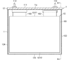
- FIG. 3 is a cross-sectional view taken at the position of the cutting line AA drawn in FIG.
- the zinc secondary battery 1 shown in FIGS. 1, 2 and 3 is a nickel-zinc battery.
- the zinc secondary battery 1 may be a zinc secondary battery other than the nickel-zinc battery.
- the zinc secondary battery 1 includes a case 11 and a lid 12 as shown in FIGS. 1, 2 and 3. Further, the zinc secondary battery 1 includes a laminated battery 13 as shown in FIGS. 2 and 3.
- the laminated battery 13 includes a laminated body 101 in which a plurality of coated positive electrodes 131 and a plurality of coated negative electrodes 132 (all of which see FIG. 4) are laminated, a plurality of positive electrode current collecting tabs 102, and a plurality of negative electrode current collecting tabs 103. And. That is, the zinc secondary battery 1 includes a laminate 101, a plurality of positive electrode current collecting tabs 102, and a plurality of negative electrode current collecting tabs 103.
- the plurality of positive electrode current collecting tabs 102 and the plurality of negative electrode current collecting tabs 103 protrude from the laminated body 101.
- FIG. 2 shows how one positive electrode current collecting tab 102 and one negative electrode current collecting tab 103 protrude.
- the tips of the plurality of positive electrode current collecting tabs 102 are aggregated. Further, the tips of the plurality of negative electrode current collecting tabs 103 are aggregated.
- the case 11 has an opening 11a.
- the case 11 houses the laminated battery 13 (laminated body 101, a plurality of positive electrode current collecting tabs 102, and a plurality of negative electrode current collecting tabs 103).
- the lid 12 closes the opening 11a.
- the case 11 and the lid 12 form a closed container having a closed space.
- the laminated battery 13 is arranged in a closed space.
- the lid 12 includes a lid main body 111, a positive electrode terminal 112, and a negative electrode terminal 113.
- the case 11 and the lid body 111 are made of an insulator having resistance to an electrolytic solution.
- the insulator is preferably a resin, more preferably a polyolefin resin, an acrylonitrile butadiene styrene (ABS) resin or a modified polyphenylene ether resin, and particularly preferably an ABS resin or a modified polyphenylene ether resin.
- the case 11 has a rectangular parallelepiped box-like shape, and the case 11 accommodates a laminated body 101 having a plate-like and rectangular planar shape. More specifically, the case 11 includes a side wall 121, a side wall 122, a side wall 123, a side wall 124, and a bottom wall 125, as shown in FIGS. 1, 2, and 3.
- the side wall 121 and the side wall 122 are parallel to the laminated body 101.
- the side wall 123, the side wall 124, and the bottom wall 125 are perpendicular to the laminated body 101.
- the side wall 121 and the side wall 122 face each other with the laminated battery 13 interposed therebetween.
- the side wall 123 and the side wall 124 face each other with the laminated battery 13 interposed therebetween.
- the opening 11a and the bottom wall 125 face each other with the laminated battery 13 interposed therebetween.
- the side wall 123, the side wall 124 and the bottom wall 125 connect the end portion of the side wall 121 and the end portion of the side wall 122.
- the opening 11a is formed between the end of the side wall 121 and the end of the side wall 122.
- the positive electrode terminal 112 and the negative electrode terminal 113 are made of a conductor.
- the conductor is preferably a metal or alloy.
- the positive electrode terminal 112 and the negative electrode terminal 113 are arranged so as to penetrate the lid main body 111 made of an insulator.
- the positive electrode terminal 112 is connected to the tips of a plurality of positive electrode current collecting tabs 102. Further, the negative electrode terminal 113 is connected to the tips of a plurality of negative electrode current collecting tabs 103. As a result, the positive electrode terminal 112 is electrically connected to the plurality of positive electrode current collecting tabs 102. Further, the negative electrode terminal 113 is electrically connected to a plurality of negative electrode current collecting tabs 103. By establishing these electrical connections, in the zinc secondary battery 1, the negative electrode terminal is connected from the positive electrode terminal 112 via the plurality of positive electrode current collecting tabs 102, the laminate 101, and the plurality of negative electrode current collecting tabs 103. The charging current toward 113 flows. Further, a discharge current flowing from the negative electrode terminal 113 to the positive electrode terminal 112 via the plurality of negative electrode current collecting tabs 103, the laminate 101, and the plurality of positive electrode current collecting tabs 102.
- FIG. 4 is a perspective view schematically showing a main part of the laminated battery 13 included in the zinc secondary battery 1.
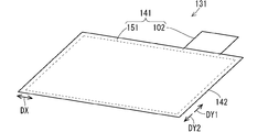
- FIG. 5 is a perspective view schematically showing a coated positive electrode 131 provided in the zinc secondary battery 1.
- FIG. 6 is a perspective view schematically showing a coated negative electrode 132 provided in the zinc secondary battery 1.
- the laminated battery 13 includes a plurality of coated positive electrodes 131 and a plurality of coated negative electrodes 132 constituting the laminated body 101.
- the plurality of coated positive electrodes 131 and the plurality of coated negative electrodes 132 are overlapped with each other by alternately arranging one of each.
- a coated positive electrode 131 and a coated negative electrode 132 adjacent thereto constitute one battery constituting the laminated battery 13.
- the number of coated positive electrodes 131 and the number of coated negative electrodes 132 may be increased or decreased according to the specifications of the zinc secondary battery 1.
- the number of coated negative electrodes 132 is one more than that of the coated positive electrode 131 as shown in FIG. 4, rather than the same number of coated positive electrodes 131 and the number of coated negative electrodes 132. It is preferable to configure the laminate 101 so that the coated negative electrodes 132 are located on both sides of the coated positive electrode 131.
- Each coated positive electrode 131 includes a positive electrode 141 and a positive electrode coating 142 that covers the positive electrode 141.
- Each positive electrode 141 includes a positive electrode plate 151 and a positive electrode current collecting tab 102.
- each coated negative electrode 132 includes a negative electrode 143 and a negative electrode coating 144 that covers the negative electrode 143.
- Each negative electrode 143 includes a negative electrode plate 153 and a negative electrode current collecting tab 103. That is, the laminated body 101 includes a plurality of positive electrode plates 151, each of which constitutes a positive electrode 141, and a plurality of negative electrode plates 153, each of which constitutes a negative electrode 143.
- a plurality of positive electrode current collecting tabs 102 and a plurality of negative electrode current collecting tabs 103 protrude from each other at different positions of the end 101Y1 of the laminated body 101.
- the end portion 101Y1 constitutes one side in the rectangular planar shape formed by the laminated body 101.
- Each positive electrode current collecting tab 102 is arranged at the same position when the laminated body 101 is viewed in a plan view from the thickness direction. Therefore, in the laminated body 101, the plurality of positive electrode current collecting tabs 102 project from the same position when viewed in a plan view from the thickness direction toward the same direction.
- the tips of the plurality of positive electrode current collecting tabs 102 projecting in this embodiment are aggregated and electrically connected to each other.
- each negative electrode current collecting tab 103 is also arranged at the same position when the laminated body 101 is viewed in a plan view from the thickness direction. Therefore, in the laminated body 101, the plurality of negative electrode current collecting tabs 103 also project from the same position in the plan view from the thickness direction toward the same direction.
- the tips of the plurality of negative electrode current collector tabs 103 protruding in this embodiment are aggregated and electrically connected to each other, and further electrically connected to the negative electrode current collector plate 15.
- the protruding positions of the plurality of positive electrode current collecting tabs 102 and the protruding positions of the plurality of negative electrode current collecting tabs 103 are separated in the direction DX perpendicular to the direction DY1 in which the respective current collecting tabs protrude from the laminated body 101. As a result, it is possible to prevent the plurality of negative electrode current collecting tabs 103 from being electrically short-circuited with the plurality of positive electrode current collecting tabs 102.
- the plurality of positive electrode current collecting tabs 102 and the plurality of negative electrode current collecting tabs 103 project from the laminate 101 in the same direction DY1.
- the number of places where a preventive measure against an electrical short circuit between the positive electrode current collector and the negative electrode current collector is required is reduced.
- the countermeasure is necessary in the vicinity of the end 101Y1, but the countermeasure is not required in the vicinity of the end 101Y2 facing the end 101Y1. ..
- FIG. 7 is a perspective view schematically showing a first structural example of the positive electrode 141 provided in the zinc secondary battery 1.
- FIG. 8 is a perspective view schematically showing a first structural example of the negative electrode 143 provided in the zinc secondary battery 1.
- the positive electrode plate 151 includes a positive electrode current collector 171 and a positive electrode active material layer 172.
- the negative electrode plate 153 includes a negative electrode current collector 174 and a negative electrode active material layer 175.
- the positive electrode current collector tab 102 is connected to the positive electrode current collector 171. Further, the negative electrode current collector tab 103 is connected to the negative electrode current collector 174.
- the positive electrode active material layer 172 is arranged around the positive electrode current collector 171. Further, the negative electrode active material layer 175 is arranged around the negative electrode current collector 174. However, the positive electrode active material layer 172 is not arranged in the band-shaped region on one side of the positive electrode current collector 171 including the connecting portion of the positive electrode current collector tab 102. Further, the negative electrode active material layer 175 is not arranged in the band-shaped region on one side of the negative electrode current collector 174 including the connecting portion of the negative electrode current collector tab 103.
- the positive electrode current collecting tab 102 and the negative electrode current collecting tab 103 are composed of tab leads. As shown in FIG. 7, the positive electrode current collecting tab 102 includes a positive electrode current collecting tab root portion 181 and a positive electrode current collecting tab tip portion 182. Further, as shown in FIG. 8, the negative electrode current collecting tab 103 includes a negative electrode current collecting tab root portion 183 and a negative electrode current collecting tab tip portion 184.
- the tab lead is made of a conductor, preferably a metal or alloy.
- the tab lead constituting the positive electrode current collecting tab 102 can be provided with nickel.
- the tab lead constituting the negative electrode current collecting tab 103 can be provided with copper.
- the tab lead preferably has a thickness of 0.05 mm or more and 0.20 mm or less, and more preferably 0.10 mm or more and 0.15 mm or less.
- the base portion 181 of the positive electrode current collector tab is a portion that is overlapped with the positive electrode current collector 171 and connected to the positive electrode current collector 171.
- the positive electrode current collector tab tip portion 182 does not overlap with the positive electrode current collector 171 and is a portion that actually protrudes from the laminated body 101.
- the negative electrode current collector tab base portion 183 is a portion that is overlapped with the negative electrode current collector 174 and connected to the negative electrode current collector 174.
- the negative electrode current collector tab tip portion 184 is a portion that does not overlap with the negative electrode current collector 174 and actually protrudes from the laminated body 101.
- the positive electrode current collecting tab 102 has a rectangular planar shape.
- the positive electrode current collecting tab tip portion 182 has the same width as the positive electrode current collecting tab root portion 181 in the direction DX.
- the negative electrode current collecting tab 103 also has a rectangular planar shape.
- the negative electrode current collecting tab tip portion 184 has the same width as the negative electrode current collecting tab root portion 183 in the direction DX.
- FIG. 9 is a perspective view schematically showing a second structural example of the positive electrode 141 provided in the zinc secondary battery 1.
- FIG. 10 is a perspective view schematically showing a second structural example of the negative electrode 143 provided in the zinc secondary battery 1.
- the second structural example of the positive electrode 141 and the negative electrode 143 is different from the first structural example of the positive electrode 141 and the negative electrode 143 mainly in the following points. Regarding points not described below, the same configuration as that adopted in the first structural example of the positive electrode 141 and the negative electrode 143 is also adopted in the second structural example of the positive electrode 141 and the negative electrode 143.
- the width of the positive electrode current collecting tab tip portion 182 in the direction DX is narrower than the width of the positive electrode current collecting tab root portion 181. Further, the positive electrode current collecting tab tip portion 182 is connected to the vicinity of one end of the positive electrode current collecting tab root portion 181 in the direction DX. Therefore, the positive electrode current collecting tab 102 has an L-shaped or T-shaped planar shape.
- the width of the negative electrode current collecting tab tip portion 184 in the direction DX is also narrower than the width of the negative electrode current collecting tab root portion 183. Further, the negative electrode current collecting tab tip portion 184 is connected to the vicinity of one end of the negative electrode current collecting tab root portion 183 in the direction DX. Therefore, the negative electrode current collecting tab 103 has an L-shaped or T-shaped planar shape.
- FIG. 11 is a perspective view schematically showing a third structural example of the positive electrode 141 provided in the zinc secondary battery 1.
- FIG. 12 is a perspective view schematically showing a third structural example of the negative electrode 143 provided in the zinc secondary battery 1.
- the third structural example of the positive electrode 141 and the negative electrode 143 is different from the first structural example of the positive electrode 141 and the negative electrode 143 mainly in the following points. Regarding points not described below, the same configuration as that adopted in the first structural example of the positive electrode 141 and the negative electrode 143 is also adopted in the third structural example of the positive electrode 141 and the negative electrode 143.
- the positive electrode current collector tab 102 is made of the same material as the material constituting the positive electrode current collector 171 and is continuous with the positive electrode current collector 171.
- the negative electrode current collector tab 103 is made of the same material as the material constituting the negative electrode current collector 174, and is continuous with the negative electrode current collector 174.
- the first and second structural examples of the positive electrode 141 as compared with the third structural example of the positive electrode 141, a member having a complicated shape in which the positive electrode current collector tab 102 and the positive electrode current collector 171 are integrated is manufactured. There is an advantage that the production efficiency of the positive electrode 141 can be increased. Further, the first and second structural examples of the negative electrode 143 are members having a complicated shape in which the negative electrode current collector tab 103 and the negative electrode current collector 174 are integrated as compared with the third structural example of the negative electrode 143. It has an advantage that the manufacturing efficiency of the negative electrode 143 can be increased without the need to manufacture the negative electrode 143.
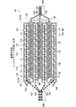
- FIG. 13 of each element is a cross-sectional view schematically showing a main part of the laminated battery 13 provided in the zinc secondary battery 1.
- the laminated battery 13 includes a positive electrode current collector 171, a positive electrode active material layer 172, a positive electrode side liquid retention member 191 and a negative electrode current collector 174, a negative electrode active material layer 175, a negative electrode side liquid retention member 192, and the negative electrode side liquid retention member 192.
- a separator 193 is provided.
- the laminated battery 13 includes an electrolytic solution in a manner of being held by the positive electrode side liquid retaining member 191 and the negative electrode side liquid retaining member 192.
- the positive electrode side liquid retention member 191 constitutes the positive electrode coating 142 described above.
- the negative electrode side liquid retaining member 192 and the separator 193 form the negative electrode coating 144 described above.
- the positive electrode current collector 171 has a plate-like or foil-like shape.
- the positive electrode current collector 171 is made of a conductor.
- the conductor is preferably made of nickel or a nickel alloy.
- the positive electrode current collector 171 is preferably made of a porous body, and more preferably made of a foam. In such a case, the area of the interface where the positive electrode current collector 171 and the positive electrode active material layer 172 come into contact with each other can be widened, and the efficiency of current collection can be increased.
- the positive electrode current collector 171 is drawn by a broken line, which means that when the positive electrode current collector 171 is made of a porous body, the positive electrode current collector 171 has holes in the positive electrode active material layer 172. It is based on the fact that the contained positive electrode active material and the like will invade, and in such a case, it will be difficult to grasp the positive electrode current collector 171 and the positive electrode active material layer 172 as separate components. be.
- the positive electrode active material layer 172 contains a positive electrode active material.
- the positive electrode active material preferably contains at least one selected from the group consisting of nickel hydroxide and nickel oxyhydroxide.
- the positive electrode active material layer 172 is formed by, for example, uniformly coating a paste containing the positive electrode active material and the dispersion medium on the positive electrode current collector 171 to form a coating film, and evaporating the dispersion medium from the formed coating film. ,It is formed.
- the positive electrode active material layer 172 or the paste may contain a binder.
- the press treatment may be performed on the composite including the positive electrode current collector 171 and the positive electrode active material layer 172. In such a case, the positive electrode active material layer 172 is suppressed from falling off, and the electrode density of the positive electrode 141 is improved.
- the zinc secondary battery 1 includes a positive electrode side liquid retention member 191.
- the positive electrode side liquid retaining member 191 has a sheet-like shape.
- the positive electrode side liquid retaining member 191 covers the entire positive electrode active material layer 172.
- the positive electrode side liquid retaining member 191 may wrap the entire positive electrode active material layer 172.
- the positive electrode side liquid retention member 191 holds the electrolytic solution. As a result, the electrolytic solution is distributed throughout the positive electrode active material layer 172.
- the positive electrode side liquid retaining member 191 is preferably made of a non-woven fabric, a water-absorbent resin, a liquid-retaining resin, a porous sheet or a spacer, and more preferably made of a non-woven fabric.
- the positive electrode side liquid retaining member 191 When the positive electrode side liquid retaining member 191 is provided with a non-woven fabric, the electrode reaction at the positive electrode 141 can be promoted, and the coated positive electrode 131 can be manufactured at low cost.
- the positive electrode side liquid retaining member 191 preferably has a thickness of 0.01 mm or more and 0.20 mm or less. In such a case, the positive electrode side liquid retaining member 191 can hold a sufficient amount of the electrolytic solution while suppressing the size of the coated positive electrode 131 from increasing.
- the negative electrode current collector 174 has a plate-like, foil-like or net-like shape.
- the negative electrode current collector 174 is made of a conductor.
- the conductor is preferably made of copper.
- the negative electrode current collector 174 is preferably made of foil, expanded metal or punching metal, and more preferably made of expanded metal. When the negative electrode current collector 174 is provided with expanded metal, the negative electrode current collector 174 can hold the negative electrode active material layer 175 having a sufficient amount.
- the negative electrode active material layer 175 contains a negative electrode active material.
- the negative electrode active material preferably contains at least one selected from the group consisting of zinc, zinc oxide, zinc alloys and zinc compounds, and more preferably at least one selected from the group consisting of zinc, zinc oxide and calcium zincate. Includes seeds, particularly preferably zinc and zinc oxide.
- the negative electrode active material preferably has powdery properties. In such a case, the area of the surface on which the negative electrode active material is exposed can be increased, whereby the current that can be passed through the negative electrode 143 can be increased.
- the negative electrode active material layer 175 is formed, for example, by applying an object to be coated containing a powder of the negative electrode active material onto the negative electrode current collector 174.
- the negative electrode active material layer 175 or the object to be coated may contain a binder.
- the binder includes, for example, polytetrafluoroethylene particles.
- the press treatment may be performed on the composite including the negative electrode current collector 174 and the negative electrode active material layer 175. In such a case, the negative electrode active material layer 175 is suppressed from falling off, and the electrode density of the negative electrode 143 is improved.
- the negative electrode active material layer 175 may have a gel-like property. When the negative electrode active material layer 175 has a gel-like property, the negative electrode active material layer 175 contains an electrolytic solution and a thickener in addition to the negative electrode active material.
- Thickeners preferably include polyvinyl alcohol, polyacrylate, carboxymethyl cellulose (CMC) or alginic acid, and more preferably polyacrylate. When the thickener contains polyacrylate, the chemical resistance of the thickener to a strongly alkaline electrolytic solution is enhanced.
- the zinc alloy is preferably a mercury- and lead-free zinc alloy.
- the zinc alloy is preferably 0.01% by mass or more and 0.1% by mass or less of indium, 0.005% by mass or more and 0.02% by mass or less of bismuth, and 0.0035% by mass or more and 0.015% by mass or less. Contains aluminum. When the zinc alloy contains indium and bismuth, the discharge performance of the negative electrode 143 is enhanced.
- the negative electrode active material contains a zinc alloy and has powdery properties
- the negative electrode active material preferably has a short diameter of 3 ⁇ m or more and an average particle size of 100 ⁇ m or less. In such a case, the area of the surface on which the negative electrode active material is exposed can be widened, and the negative electrode active material, the electrolytic solution, and the gelling agent can be easily mixed uniformly, so that when the zinc secondary battery 1 is manufactured. The handling of the negative electrode active material of the above becomes easy.
- the zinc secondary battery 1 includes a negative electrode side liquid retention member 192.
- the negative electrode side liquid retaining member 192 has a sheet-like shape.
- the negative electrode side liquid retaining member 192 covers the entire negative electrode active material layer 175.
- the negative electrode side liquid retaining member 192 may wrap the entire negative electrode active material layer 175.
- the negative electrode side liquid retention member 192 holds the electrolytic solution. As a result, the electrolytic solution is distributed throughout the negative electrode active material layer 175.
- the negative electrode side liquid retaining member 192 is preferably made of a non-woven fabric, a water-absorbent resin, a liquid-retaining resin, a porous sheet or a spacer, and more preferably made of a non-woven fabric.
- the negative electrode side liquid retaining member 192 is provided with a non-woven fabric, the electrode reaction at the negative electrode 143 can be promoted, and the coated negative electrode 132 can be manufactured at low cost.
- the negative electrode side liquid retaining member 192 preferably has a thickness of 0.01 mm or more and 0.20 mm or less, more preferably 0.02 mm or more and 0.20 mm or less, and particularly preferably 0.02 mm or more. It has a thickness of 0.15 mm or less, more preferably 0.02 mm or more and 0.10 mm or less, and most preferably 0.02 mm or more and 0.06 mm or less.
- the negative electrode side liquid retaining member 192 has a thickness in these ranges, the negative electrode side liquid retaining member 192 is allowed to hold a sufficient amount of electrolytic solution while suppressing the overall size of the coated negative electrode 132 in a compact manner without waste. Can be done.
- the electrolytic solution held by the positive electrode side liquid retaining member 191 and the negative electrode side liquid retaining member 192 preferably consists of an aqueous solution of hydroxide.
- the hydroxide is preferably an alkali metal hydroxide or ammonium hydroxide, more preferably an alkali metal hydroxide, and particularly preferably potassium hydroxide, sodium hydroxide or lithium hydroxide, most preferably. Desirably, potassium hydroxide.
- the zinc compound may be dissolved in the electrolytic solution.
- the zinc compound is preferably zinc oxide or zinc hydroxide.
- the zinc and / or zinc oxide constituting the negative electrode active material layer 175 is suppressed from being self-dissolved in the electrolytic solution.
- a gelling agent may be added to the electrolytic solution.
- the gelling agent preferably consists of a polymer that absorbs and swells the solvent contained in the electrolytic solution, and more preferably consists of polyethylene oxide, polyvinyl alcohol, polyacrylamide or starch. When the gelling agent is added to the electrolytic solution, it is possible to prevent the electrolytic solution from gelling and leaking from the case 11.
- the electrolytic solution and the positive electrode active material may be mixed to form a positive electrode mixture.
- the electrolytic solution and the negative electrode active material may be mixed to form a negative electrode mixture.
- Separator 193 has a sheet-like shape.
- the separator 193 preferably covers or wraps the negative electrode active material layer 175 with the negative electrode side liquid retaining member 192 interposed therebetween.
- One or two sides of the outer edge of the separator 193 are open to project the negative electrode current collecting tab 103.
- Separator 193 contains a porous base material and a hydroxide ion conductive layered compound that closes the pores of the porous base material.
- the hydroxide ion conductive layered compound is a layered double hydroxide (LDH) and / or a layered double hydroxide (LDH) -like compound.
- the separator 193 is a separator containing LDH and / or LDH-like compound, and selectively passes hydroxide ions by utilizing the hydroxide ion conductivity of LDH and / or LDH-like compound. Defined as a thing.
- LDH-like compound is a hydroxide and / or oxide having a layered crystal structure similar to LDH, although it may not be called LDH, and can be said to be an equivalent of LDH.
- LDH can be interpreted as including LDH-like compounds as well as LDH.
- the hydroxide ion conductive layered compound closes the pores of the porous base material, and the hydroxide ion conductive layered compound is connected between the upper surface and the lower surface of the separator 193 sandwiching the porous base material. ..
- the separator 193 exhibits hydroxide ion conductivity while exhibiting gas impermeableness. In other words, it functions as a separator exhibiting hydroxide ion conductivity.
- the pores of the porous substrate do not have to be completely closed, and a small amount of residual pores may be present.
- the hydroxide ion conductive layered compound is incorporated over the entire area of the porous substrate in the thickness direction.
- the thickness of the separator 193 is preferably 3 ⁇ m to 80 ⁇ m, more preferably 3 ⁇ m to 60 ⁇ m, and even more preferably 3 ⁇ m to 40 ⁇ m.
- the separator separates the positive electrode plate and the negative electrode plate so that hydroxide ions can be conducted when they are incorporated in a zinc secondary battery.
- Preferred separators have gas impermeable and / or water impermeable.
- the separator is preferably densified to have gas impermeable and / or water impermeable.
- “having gas impermeable” in the present specification means helium gas on one side of the object to be measured in water. This means that no bubbles are generated due to helium gas from the other surface side even if they are brought into contact with each other with a differential pressure of 0.5 atm.
- “having water impermeable” means that water in contact with one side of an object to be measured is defined as described in International Publication No. 2016/076047 and International Publication No. 2016/067884. It means that it does not penetrate to the other side. That is, in the present specification, the fact that the separator has gas impermeableness and / or water impermeability means that the separator has a high degree of denseness that does not allow gas or water to pass through, and is water permeable or gas. It means that it is not a permeable porous film or other porous material.
- the separator selectively passes only hydroxide ions due to its hydroxide ion conductivity, and can exhibit a function as a battery separator.
- a separator By incorporating such a separator into a zinc secondary battery, an extremely effective configuration is realized in which the penetration of the separator by the zinc dendrite generated during charging is physically prevented to prevent a short circuit between the positive and negative electrodes.
- the separator since the separator has hydroxide ion conductivity, it is possible to efficiently move the required hydroxide ion between the positive electrode plate and the negative electrode plate, so that the charge / discharge reaction in the positive electrode plate and the negative electrode plate can be performed. Is realized.
- the porous base material is preferably composed of a polymer material.
- the polymer porous substrate has 1) flexibility (hence, it is hard to break even if it is thinned), 2) easy to increase the porosity, and 3) easy to increase the conductivity (while increasing the porosity). It has the advantages of being easy to manufacture and handle) (because the thickness can be reduced). Further, taking advantage of the flexibility of 1) above, 5) a hydroxide ion conductive separator containing a porous base material made of a polymer material can be easily bent or sealed and bonded. There is also the advantage of.
- Preferred examples of the polymer material include polystyrene, polyether sulfone, polypropylene, epoxy resin, polyphenylene sulfide, fluororesin (tetrafluororesin: PTFE, etc.), cellulose, nylon, polyethylene and any combination thereof. .. More preferably, from the viewpoint of a thermoplastic resin suitable for heat pressing, polystyrene, polyether sulfone, polypropylene, epoxy resin, polyphenylene sulfide, fluororesin (tetrafluororesin: PTFE, etc.), nylon, polyethylene and any of them. Examples include the combination of. All of the various preferable materials described above have alkali resistance as resistance to the electrolytic solution of the battery. Particularly preferable polymer materials are polyolefins such as polypropylene and polyethylene, and most preferably polypropylene or polyethylene, because they are excellent in heat resistance, acid resistance and alkali resistance, and are low in cost.
- the hydroxide ion conductive layered compound is incorporated over the entire thickness direction of the polymer porous substrate (for example, most or almost all the pores inside the polymer porous substrate are hydroxide ion conductive layered compounds). It is particularly preferable that it is buried).
- a polymer porous substrate a commercially available polymer microporous membrane can be preferably used.
- LDH is composed of a plurality of hydroxide basic layers and an intermediate layer interposed between the plurality of hydroxide basic layers.
- the basic hydroxide layer is mainly composed of metal elements (typically metal ions) and OH groups.
- Intermediate layer of LDH is composed of anionic and H 2 O.
- the anion is a monovalent or higher anion, preferably a monovalent or divalent ion.
- the anions in LDH contain OH ⁇ and / or CO 3 2- .
- LDH also has excellent ionic conductivity due to its unique properties.
- LDH is M 2+ 1-x M 3+ x (OH) 2 A n- x / n ⁇ mH 2 O (in the formula, M 2+ is a divalent cation and M 3+ is a trivalent cation. It is a cation, An- is an n-valent anion, n is an integer of 1 or more, x is 0.1 to 0.4, and m is 0 or more). It is known as a representative.
- M 2+ can be any divalent cation, but preferred examples include Mg 2+ , Ca 2+ and Zn 2+ , and more preferably Mg 2+ .
- M 3+ can be any trivalent cation, with preferred examples being Al 3+ or Cr 3+ , more preferably Al 3+ .
- a n- may be any anion, preferred examples OH - and CO 3 2- and the like. Accordingly, in the above basic formula, M 2+ comprises Mg 2+, M 3+ comprises Al 3+, A n-is OH - and / or CO preferably contains 3 2-.
- n is an integer greater than or equal to 1, but is preferably 1 or 2.
- x is 0.1 to 0.4, preferably 0.2 to 0.35.
- m is an arbitrary number meaning the number of moles of water, and is a real number greater than or equal to 0, typically greater than or equal to 0 or greater than or equal to 1.
- the above basic composition formula is merely a formula of the "basic composition” generally exemplified with respect to LDH, and the constituent ions can be appropriately replaced.
- the constituent ions can be replaced with some or all of the M 3+ in the basic formula tetravalent or higher valency cations (e.g. Ti 4+), that case, the anion A n in the basic composition formula
- the coefficient x / n of ⁇ may be changed as appropriate.
- the hydroxide basic layer of LDH contains Mg, Al, Ti and OH groups in terms of exhibiting excellent alkali resistance.
- the hydroxide basic layer may contain other elements or ions as long as it contains Mg, Al, Ti and OH groups.
- the LDH or hydroxide basic layer may contain Y and / or Zn.
- Al or Ti may not be contained in the LDH or hydroxide basic layer.
- the hydroxide basic layer preferably contains Mg, Al, Ti and OH groups as main components. That is, the hydroxide basic layer is preferably mainly composed of Mg, Al, Ti and OH groups. Therefore, the hydroxide basic layer is typically composed of Mg, Al, Ti, OH groups and, in some cases, unavoidable impurities.
- the atomic ratio of Ti / Al in LDH is preferably 0.5-12, more preferably 1.0-12.
- EDS Energy Dispersive X-ray Analysis
- the atomic ratio of Ti / (Mg + Ti + Al) in LDH is preferably 0.1 to 0.7, more preferably 0.2. It is ⁇ 0.7.
- the atomic ratio of Al / (Mg + Ti + Al) in LDH is preferably 0.05 to 0.4, more preferably 0.05 to 0.25.
- the atomic ratio of Mg / (Mg + Ti + Al) in LDH is preferably 0.2 to 0.7, more preferably 0.2 to 0.6.
- an EDS analyzer for example, X-act, manufactured by Oxford Instruments
- X-act for example, X-act, manufactured by Oxford Instruments
- the hydroxide basic layer of LDH may contain Ni, Al, Ti and OH groups.
- the hydroxide basic layer may contain other elements or ions as long as it contains Ni, Al, Ti and OH groups.
- the hydroxide basic layer preferably contains Ni, Al, Ti and OH groups as main components. That is, the hydroxide basic layer is preferably mainly composed of Ni, Al, Ti and OH groups. Therefore, the hydroxide basic layer is typically composed of Ni, Al, Ti, OH groups and, in some cases, unavoidable impurities.
- the atomic ratio of Ti / (Ni + Ti + Al) in LDH is preferably 0.10 to 0.90, more preferably 0.20 to 0.80. It is more preferably 0.25 to 0.70, and particularly preferably 0.30 to 0.61.
- EDS Energy Dispersive X-ray Analysis
- the hydroxide ion conductive layered compound may contain not only LDH but also Ti so much that titania is by-produced. That is, the hydroxide ion conductive layered compound may further contain titania. It can be expected that the content of titania increases the hydrophilicity and the wettability with the electrolytic solution (that is, the conductivity is improved).
- the LDH-like compound preferably contains Mg and one or more elements containing at least Ti selected from the group consisting of Ti, Y and Al.
- an LDH-like compound which is a hydroxide and / or an oxide having a layered crystal structure containing at least Mg and Ti as the hydroxide ion conductive substance instead of the conventional LDH, the alkali resistance is improved. It is possible to provide a hydroxide ion conductive separator which is excellent and can suppress a short circuit caused by zinc dendrite more effectively.
- a preferred LDH-like compound is a hydroxide and / or oxide having a layered crystal structure containing Mg and at least one element containing at least Ti selected from the group consisting of Ti, Y and Al.
- Typical LDH-like compounds are composite hydroxides and / or composite oxides of Mg, Ti, optionally Y and optionally Al, particularly preferably composite hydroxides and / of Mg, Ti, Y and Al. Or it is a composite oxide.
- the element may be replaced with another element or ion to the extent that the basic properties of the LDH-like compound are not impaired, but the LDH-like compound preferably does not contain Ni.
- LDH-like compounds can be identified by X-ray diffraction. Specifically, when X-ray diffraction is performed on the surface of a separator containing an LDH-like compound, it is typically in the range of 5 ° ⁇ 2 ⁇ ⁇ 10 °, and more typically 7 ° ⁇ 2 ⁇ ⁇ 10. Peaks derived from LDH-like compounds are detected in the ° range.
- LDH as described above, exchangeable anions and H 2 O as an intermediate layer between the stacked hydroxide base layer is present, a substance having alternating lamination structure.
- the peak is typically detected in the above-mentioned range shifted to the lower angle side than the above-mentioned peak position of LDH.
- the interlayer distance of the layered crystal structure constituting the LDH-like compound which is determined by applying the value of 2 ⁇ corresponding to the peak derived from the LDH-like compound detected by X-ray diffraction to the Bragg equation, is 0. It is typically .883 nm to 1.8 nm, and more typically 0.883 nm to 1.3 nm.
- the atomic ratio of Mg / (Mg + Ti + Y + Al) in the LDH-like compound is preferably 0.03 to 0.25, more preferably 0.05 to 0. It is 2.
- the atomic ratio of Ti / (Mg + Ti + Y + Al) in the LDH-like compound is preferably 0.40 to 0.97, more preferably 0.47 to 0.94.
- the atomic ratio of Y / (Mg + Ti + Y + Al) in the LDH-like compound is preferably 0 to 0.45, more preferably 0 to 0.37.
- the atomic ratio of Al / (Mg + Ti + Y + Al) in the LDH-like compound is preferably 0 to 0.05, more preferably 0 to 0.03.
- the LDH-like compound satisfies the above range, the alkali resistance of the separator 193 can be further improved, and the effect of suppressing a short circuit caused by zinc dendrite in the separator 193 (that is, dendrite resistance) can be obtained. , Can be obtained better.
- LDH is M 2+ 1-x M 3+ x (OH) 2 Ann- x / n ⁇ mH 2 O (in the formula, M 2+ is a divalent cation and M 3+ is a trivalent cation. It is a cation, and An - is an n-valent anion, n is an integer of 1 or more, x is 0.1 to 0.4, and m is 0 or more).
- the atomic ratio of LDH-like compounds generally deviates from the basic composition formula of LDH. Therefore, it can be said that the LDH-like compound generally has a composition ratio (atomic ratio) different from that of the conventional LDH.
- an EDS analyzer for example, X-act, manufactured by Oxford Instruments
- X-act for example, X-act, manufactured by Oxford Instruments
- the method for producing the separator 193 is not particularly limited, and the method for producing the already known LDH separator (or LDH-containing functional layer and composite material) (for example, International Publication No. 2013/118561, International Publication No. 2016/076047, International Publication No. It can be prepared by changing the conditions (particularly LDH raw material composition) of 2016/067884, International Publication No. 2019/124270 and International Publication No. 2019/124212) as they are or by appropriately changing them.
- LDH separator or LDH-containing functional layer and composite material
- a porous base material is prepared, and (2) a mixed sol of alumina and titania (when forming LDH) or ii) titania sol (or further yttrium sol and / or) is prepared on the porous base material.
- a solution containing (alumina sol) (when forming an LDH-like compound) is applied and dried to form a titania-containing layer, and (3) magnesium ion (Mg 2+ ) and urea (or further yttrium ion (Y 3+ )).
- the porous base material is hydrothermally heat-treated in the raw material aqueous solution containing (4) the hydroxide ion conductive layered compound on the porous base material and / or the porous base material.
- the pH value rises due to the generation of ammonia in the solution by utilizing the hydrolysis of urea, and the coexisting metal ions are hydroxide and / or oxidized. It is considered that a hydroxide ion conductive layered compound (that is, LDH and / or LDH-like compound) can be obtained by forming an object.
- a hydroxide ion conductive layered compound that is, LDH and / or LDH-like compound
- anions can be obtained as carbonate ion type LDH.
- the application of the mixed sol solution in the above step (2) to the substrate is performed. It is preferable to carry out the method so that the mixed sol solution permeates the whole or most of the inside of the base material. By doing so, most or almost all the pores inside the porous substrate can be finally filled with the hydroxide ion conductive layered compound.
- a preferable coating method include a dip coating, a filtration coating and the like, and a dip coating is particularly preferable. By adjusting the number of times of application of the dip coat or the like, the amount of adhesion of the mixed sol solution can be adjusted.
- the base material coated with the mixed sol solution by dip coating or the like may be dried and then the above steps (3) and (4) may be carried out.
- the pressing method may be, for example, a roll press, a uniaxial pressure press, a CIP (cold isotropic pressure press), or the like, and is not particularly limited, but is preferably a roll press.
- This press is preferably performed while heating because the pores of the polymer porous substrate can be sufficiently closed with the hydroxide ion conductive layered compound by softening the polymer porous substrate.
- the polymer porous base material is polypropylene or polyethylene, it is preferable to heat at 60 ° C. to 200 ° C.
- the residual pores of the separator 193 can be significantly reduced.
- the separator 193 can be made extremely dense, and therefore short circuits caused by zinc dendrites can be suppressed even more effectively.
- the morphology of the residual pores can be controlled by appropriately adjusting the roll gap and the roll temperature, whereby the separator 193 with the desired density can be obtained.
- the denseness of the above-mentioned separator can be evaluated by the He transparency.
- the separator has a He transmittance of 10 cm / min ⁇ atm or less, more preferably 5.0 cm / min ⁇ atm or less, and further preferably 1.0 cm / min ⁇ atm or less per unit area. It can be said that a separator having a He transmittance within such a range has extremely high density. That is, a separator having a He permeability of 10 cm / min ⁇ atm or less can block the passage of substances other than hydroxide ions at a high level. For example, in the case of a zinc secondary battery incorporating this, Zn permeation (typically zinc ion or zinc acid ion permeation) can be suppressed extremely effectively in the electrolytic solution.
- Zn permeation typically zinc ion or zinc acid ion permeation
- the He permeability is determined through a step of supplying He gas to one surface of the separator and allowing the He gas to permeate through the separator, and a step of calculating the He permeability and evaluating the denseness of the hydroxide ion conduction separator. Be measured.
- the He permeability is determined by the formula of F / (P ⁇ S) using the permeation amount F of the He gas per unit time, the differential pressure P applied to the separator when the He gas permeates, and the membrane area S through which the He gas permeates. calculate.
- He gas has the smallest structural unit among a wide variety of atoms or molecules that can constitute gas, and has extremely low reactivity. That is, He constitutes He gas by a single He atom without forming a molecule. In this respect, since hydrogen gas is composed of H 2 molecules, the He atom alone is smaller as a gas constituent unit. In the first place, H 2 gas is dangerous because it is a flammable gas.
- the negative electrode active material layer 175 is above substantially the entire main surface of the negative electrode current collector 174. It exists almost uniformly in. However, after the charge / discharge cycle is repeated, the negative electrode active material layer 175 is unevenly present on the central portion of the main surface of the negative electrode current collector 174. This phenomenon is called shape change. The shape change is considered to occur due to the self-dissolution of zinc constituting the negative electrode active material layer 175 in the electrolytic solution.
- the peripheral portion of the negative electrode current collector 174 is likely to be electrically short-circuited with the positive electrode current collector 171.
- the negative electrode current collector 174 is made of an expanded metal, burrs, sasakure, etc. that are likely to occur at the ends of the expanded metal break through the negative electrode side liquid retention member 192 and the separator 193, and the expanded metal and the positive electrode current collector 171 Is likely to be electrically short-circuited.
- FIGS. 14 to 16 are cross-sectional views schematically showing the main parts of the laminated battery 93 provided in the zinc secondary battery of the reference example. be.
- FIG. 14 shows an ideal state.
- 15 and 16 show the actual state.
- FIG. 15 shows the state before the shape change occurs.
- FIG. 16 shows the state after the shape change has occurred.
- a plurality of positive electrode current collecting tabs 102 project from the laminated body 101 in the direction DX1. Further, a plurality of negative electrode current collecting tabs 103 project from the laminated body 101 in the direction DX2.
- the tips of the plurality of positive electrode current collector tabs 102 are aggregated and connected to the positive electrode current collector plate 995 connected to the positive electrode terminal 112. Further, the tips of the plurality of negative electrode current collector tabs 103 are aggregated and connected to the negative electrode current collector plate 996 connected to the negative electrode terminal 113.
- the tips of the plurality of positive electrode current collector tabs 102 are aggregated, so that the stress S having a component toward the center in the thickness direction of the laminated body 101 is a plurality of positive electrode current collectors. Joined the electric tab 102. Further, by aggregating the tips of the plurality of negative electrode current collecting tabs 103, a stress S having a component toward the center in the thickness direction of the laminated body 101 is applied to the plurality of negative electrode current collecting tabs 103.
- the negative electrode active material layer 175 exists substantially uniformly on substantially the entire main surface of the negative electrode current collector 174.
- the negative electrode active material layer 175 is unevenly present on the central portion of the main surface of the negative electrode current collector 174. Therefore, after repeating the charge / discharge cycle, the peripheral portion of the negative electrode current collector 174 is likely to be electrically short-circuited with the positive electrode current collector 171.
- both the vicinity of the end portion 101X1 arranged closer to the direction DX1 of the laminated body 101 and the vicinity of the end portion 101X2 arranged closer to the direction DX2 of the laminated body 101 are necessary to take measures to prevent the negative electrode current collector 174 from being electrically short-circuited with the positive electrode current collector 171.
- FIGS. 17 to 19 are cross-sectional views schematically showing a main part of a laminated battery 13 provided in the zinc secondary battery 1.
- FIG. 17 shows an ideal state.
- 18 and 19 show the actual state.
- FIG. 18 shows the state before the shape change occurs.
- FIG. 19 shows the state after the shape change has occurred.
- a plurality of positive electrode current collecting tabs 102 project from the laminated body 101 in the direction DY1. Further, the plurality of negative electrode current collecting tabs 103 also project from the laminated body 101 in the direction DY1. The tips of the plurality of positive electrode current collecting tabs 102 are aggregated and connected to the positive electrode terminals 112. Further, the tips of the plurality of negative electrode current collecting tabs 103 are aggregated and connected to the negative electrode terminals 113.
- the tips of the plurality of positive electrode current collector tabs 102 are aggregated, so that the stress S having a component toward the center in the thickness direction of the laminated body 101 is a plurality of positive electrode current collectors. Joined the electric tab 102. Further, by aggregating the tips of the plurality of negative electrode current collecting tabs 103, a stress S having a component toward the center in the thickness direction of the laminated body 101 is applied to the plurality of negative electrode current collecting tabs 103.
- the negative electrode active material layer 175 exists substantially uniformly on substantially the entire main surface of the negative electrode current collector 174.
- the negative electrode active material layer 175 is unevenly present on the central portion of the main surface of the negative electrode current collector 174. Therefore, after repeating the charge / discharge cycle, the peripheral portion of the negative electrode current collector 174 is likely to be electrically short-circuited with the positive electrode current collector 171.
- the countermeasure is not necessary in the vicinity of the end 101Y2 facing the end 101Y1.
- the countermeasure may be any, and for example, a countermeasure of arranging an insulating tape between the negative electrode current collector 174 and the positive electrode current collector 171 can be mentioned.
- a plurality of positive electrode current collector tabs 102 are connected to the positive electrode terminal 112 via the positive electrode current collector plate 995. Further, a plurality of negative electrode current collector tabs 103 are connected to the negative electrode terminal 113 via the negative electrode current collector plate 996.
- the plurality of positive electrode current collecting tabs 102 are directly connected to the positive electrode terminals 112. Further, a plurality of negative electrode current collecting tabs 103 are directly connected to the negative electrode terminals 113.
- the zinc secondary battery 1 according to the present embodiment has an advantage over a safety test such as an overcharge test as compared with the zinc secondary battery of the reference example.
- the zinc secondary battery 1 has a higher volumetric energy density than the zinc secondary battery of the reference example. This is because, in the zinc secondary battery of the reference example, since the positive electrode current collector plate 995 and the negative electrode current collector plate 996 are arranged, spaces causing a decrease in volumetric energy density exist on both sides of the laminated body 101. However, in the zinc secondary battery 1, such a space exists only on one side of the laminated body 101.
- FIG. 20 is a top view schematically showing a module battery.
- the module battery 2 shown in FIG. 20 includes a plurality of cell batteries 21.
- Each of the plurality of cell 21 is the zinc secondary battery 1 described above.
- the lid body 111 of the cell 21 has an outer surface 111a.
- the outer surfaces 111a of all the lid main bodies 111 provided on each of the plurality of AA cells 21 face the same direction DY1.
- the plurality of cell cells 21 are arranged in the direction DZ perpendicular to the direction DY1 in which the outer surface 111a of each lid main body 111 faces.
- the module battery 2 includes a plurality of wirings 22.
- Each of the plurality of wirings 22 electrically connects the positive electrode terminal 112 provided in one of the two adjacent cell batteries 21 and the negative electrode terminal 113 provided in the other cell 21.
- the plurality of wirings 22 are concentrated on one side of the plurality of cell batteries 21. As a result, the space occupied by the plurality of wirings 22 is reduced, so that the module battery 2 can be miniaturized.
Landscapes
- Chemical & Material Sciences (AREA)
- Chemical Kinetics & Catalysis (AREA)
- Electrochemistry (AREA)
- General Chemical & Material Sciences (AREA)
- Engineering & Computer Science (AREA)
- Manufacturing & Machinery (AREA)
- Connection Of Batteries Or Terminals (AREA)
- Battery Electrode And Active Subsutance (AREA)
- Cell Electrode Carriers And Collectors (AREA)
- Secondary Cells (AREA)
- Sealing Battery Cases Or Jackets (AREA)
Priority Applications (1)
| Application Number | Priority Date | Filing Date | Title |
|---|---|---|---|
| JP2022510425A JP7382488B2 (ja) | 2020-03-23 | 2021-03-19 | 亜鉛二次電池及びモジュール電池 |
Applications Claiming Priority (2)
| Application Number | Priority Date | Filing Date | Title |
|---|---|---|---|
| JP2020050832 | 2020-03-23 | ||
| JP2020-050832 | 2020-03-23 |
Publications (1)
| Publication Number | Publication Date |
|---|---|
| WO2021193436A1 true WO2021193436A1 (ja) | 2021-09-30 |
Family
ID=77892519
Family Applications (1)
| Application Number | Title | Priority Date | Filing Date |
|---|---|---|---|
| PCT/JP2021/011397 Ceased WO2021193436A1 (ja) | 2020-03-23 | 2021-03-19 | 亜鉛二次電池及びモジュール電池 |
Country Status (2)
| Country | Link |
|---|---|
| JP (1) | JP7382488B2 (https=) |
| WO (1) | WO2021193436A1 (https=) |
Cited By (3)
| Publication number | Priority date | Publication date | Assignee | Title |
|---|---|---|---|---|
| WO2022190460A1 (ja) * | 2021-03-12 | 2022-09-15 | 日本碍子株式会社 | 亜鉛二次電池 |
| WO2023188490A1 (ja) * | 2022-03-28 | 2023-10-05 | 日本碍子株式会社 | 亜鉛二次電池 |
| JPWO2024189972A1 (https=) * | 2023-03-16 | 2024-09-19 |
Citations (5)
| Publication number | Priority date | Publication date | Assignee | Title |
|---|---|---|---|---|
| JP2001210303A (ja) * | 2000-01-28 | 2001-08-03 | Yuasa Corp | 電池用電極群 |
| US20020055037A1 (en) * | 1999-04-29 | 2002-05-09 | Kenneth Dale Rhoten | Bipolar catalytic cells |
| JP2010518585A (ja) * | 2007-02-12 | 2010-05-27 | パワージェニックス システムズ, インコーポレーテッド | 金属亜鉛型電流コレクタ |
| JP2017059529A (ja) * | 2015-09-14 | 2017-03-23 | 日本碍子株式会社 | ラミネート型ニッケル亜鉛電池セルパック及びそれを用いた電池 |
| JP2018026205A (ja) * | 2016-08-08 | 2018-02-15 | 日本碍子株式会社 | 負極構造体及びそれを備えた亜鉛二次電池 |
-
2021
- 2021-03-19 WO PCT/JP2021/011397 patent/WO2021193436A1/ja not_active Ceased
- 2021-03-19 JP JP2022510425A patent/JP7382488B2/ja active Active
Patent Citations (5)
| Publication number | Priority date | Publication date | Assignee | Title |
|---|---|---|---|---|
| US20020055037A1 (en) * | 1999-04-29 | 2002-05-09 | Kenneth Dale Rhoten | Bipolar catalytic cells |
| JP2001210303A (ja) * | 2000-01-28 | 2001-08-03 | Yuasa Corp | 電池用電極群 |
| JP2010518585A (ja) * | 2007-02-12 | 2010-05-27 | パワージェニックス システムズ, インコーポレーテッド | 金属亜鉛型電流コレクタ |
| JP2017059529A (ja) * | 2015-09-14 | 2017-03-23 | 日本碍子株式会社 | ラミネート型ニッケル亜鉛電池セルパック及びそれを用いた電池 |
| JP2018026205A (ja) * | 2016-08-08 | 2018-02-15 | 日本碍子株式会社 | 負極構造体及びそれを備えた亜鉛二次電池 |
Cited By (8)
| Publication number | Priority date | Publication date | Assignee | Title |
|---|---|---|---|---|
| WO2022190460A1 (ja) * | 2021-03-12 | 2022-09-15 | 日本碍子株式会社 | 亜鉛二次電池 |
| WO2023188490A1 (ja) * | 2022-03-28 | 2023-10-05 | 日本碍子株式会社 | 亜鉛二次電池 |
| JPWO2023188490A1 (https=) * | 2022-03-28 | 2023-10-05 | ||
| DE112022006545T5 (de) | 2022-03-28 | 2024-11-28 | Ngk Insulators, Ltd. | Zink-sekundärbatterie |
| JP7717961B2 (ja) | 2022-03-28 | 2025-08-04 | 日本碍子株式会社 | 亜鉛二次電池 |
| JPWO2024189972A1 (https=) * | 2023-03-16 | 2024-09-19 | ||
| WO2024189972A1 (ja) * | 2023-03-16 | 2024-09-19 | 日本碍子株式会社 | 亜鉛二次電池 |
| JP7810860B2 (ja) | 2023-03-16 | 2026-02-03 | 日本碍子株式会社 | 亜鉛二次電池 |
Also Published As
| Publication number | Publication date |
|---|---|
| JP7382488B2 (ja) | 2023-11-16 |
| JPWO2021193436A1 (https=) | 2021-09-30 |
Similar Documents
| Publication | Publication Date | Title |
|---|---|---|
| JP6723473B2 (ja) | 亜鉛二次電池 | |
| US20170222271A1 (en) | Secondary battery with hydroxide-ion-conducting ceramic separator | |
| JP7382488B2 (ja) | 亜鉛二次電池及びモジュール電池 | |
| JP7228706B2 (ja) | 空気極/セパレータ接合体及び亜鉛空気二次電池 | |
| JPWO2019069762A1 (ja) | 亜鉛二次電池用の負極構造体の製造方法 | |
| WO2021193407A1 (ja) | 亜鉛二次電池 | |
| JP7714410B2 (ja) | Ldhセパレータ及び亜鉛二次電池 | |
| US20250015339A1 (en) | Zinc secondary battery | |
| WO2022209010A1 (ja) | 空気極/セパレータ接合体及び金属空気二次電池 | |
| US20240413486A1 (en) | Zinc secondary battery | |
| US20230207796A1 (en) | Zinc secondary battery | |
| JP7506822B2 (ja) | ニッケル亜鉛二次電池 | |
| JP7449139B2 (ja) | 二次電池及び二次電池の製造方法 | |
| JP7516086B2 (ja) | 二次電池及びモジュール電池 | |
| JP7626646B2 (ja) | 定置型ニッケル亜鉛二次電池 | |
| JP7545569B2 (ja) | 亜鉛二次電池 | |
| WO2025163962A1 (ja) | 亜鉛二次電池 | |
| JP7577128B2 (ja) | Ldhセパレータ及び亜鉛二次電池 | |
| US20240014449A1 (en) | Zinc secondary battery | |
| JP7557613B2 (ja) | 負極及び亜鉛二次電池 | |
| WO2022209009A1 (ja) | 空気極/セパレータ接合体及び金属空気二次電池 | |
| JP2024140385A (ja) | 亜鉛二次電池 | |
| WO2024176531A1 (ja) | 亜鉛二次電池 | |
| WO2025187123A1 (ja) | 亜鉛二次電池 | |
| WO2024029364A1 (ja) | 負極板及びそれを備えた亜鉛二次電池 |
Legal Events
| Date | Code | Title | Description |
|---|---|---|---|
| 121 | Ep: the epo has been informed by wipo that ep was designated in this application |
Ref document number: 21776757 Country of ref document: EP Kind code of ref document: A1 |
|
| ENP | Entry into the national phase |
Ref document number: 2022510425 Country of ref document: JP Kind code of ref document: A |
|
| NENP | Non-entry into the national phase |
Ref country code: DE |
|
| 122 | Ep: pct application non-entry in european phase |
Ref document number: 21776757 Country of ref document: EP Kind code of ref document: A1 |