WO2021193351A1 - Asphalt finisher - Google Patents
Asphalt finisher Download PDFInfo
- Publication number
- WO2021193351A1 WO2021193351A1 PCT/JP2021/011078 JP2021011078W WO2021193351A1 WO 2021193351 A1 WO2021193351 A1 WO 2021193351A1 JP 2021011078 W JP2021011078 W JP 2021011078W WO 2021193351 A1 WO2021193351 A1 WO 2021193351A1
- Authority
- WO
- WIPO (PCT)
- Prior art keywords
- asphalt finisher
- tractor
- road
- screed
- steering
- Prior art date
Links
- 239000010426 asphalt Substances 0.000 title claims abstract description 134
- 239000000463 material Substances 0.000 claims abstract description 37
- 238000004891 communication Methods 0.000 claims description 13
- 238000003384 imaging method Methods 0.000 claims description 2
- 238000012806 monitoring device Methods 0.000 description 40
- 238000004364 calculation method Methods 0.000 description 26
- 239000010720 hydraulic oil Substances 0.000 description 18
- 238000010276 construction Methods 0.000 description 17
- 239000013256 coordination polymer Substances 0.000 description 15
- 238000012544 monitoring process Methods 0.000 description 14
- 238000013459 approach Methods 0.000 description 6
- 238000013461 design Methods 0.000 description 6
- 230000004044 response Effects 0.000 description 5
- 239000008186 active pharmaceutical agent Substances 0.000 description 4
- 239000003921 oil Substances 0.000 description 4
- 230000007246 mechanism Effects 0.000 description 3
- 238000009415 formwork Methods 0.000 description 2
- 230000032258 transport Effects 0.000 description 2
- 230000008859 change Effects 0.000 description 1
- 230000008602 contraction Effects 0.000 description 1
- 230000007423 decrease Effects 0.000 description 1
- 238000009795 derivation Methods 0.000 description 1
- 238000010586 diagram Methods 0.000 description 1
- 230000005484 gravity Effects 0.000 description 1
- 239000004973 liquid crystal related substance Substances 0.000 description 1
- 239000000203 mixture Substances 0.000 description 1
- 238000010295 mobile communication Methods 0.000 description 1
- 238000012986 modification Methods 0.000 description 1
- 230000004048 modification Effects 0.000 description 1
- 230000007480 spreading Effects 0.000 description 1
- 238000006467 substitution reaction Methods 0.000 description 1
Images


Classifications
-
- E—FIXED CONSTRUCTIONS
- E01—CONSTRUCTION OF ROADS, RAILWAYS, OR BRIDGES
- E01C—CONSTRUCTION OF, OR SURFACES FOR, ROADS, SPORTS GROUNDS, OR THE LIKE; MACHINES OR AUXILIARY TOOLS FOR CONSTRUCTION OR REPAIR
- E01C19/00—Machines, tools or auxiliary devices for preparing or distributing paving materials, for working the placed materials, or for forming, consolidating, or finishing the paving
- E01C19/48—Machines, tools or auxiliary devices for preparing or distributing paving materials, for working the placed materials, or for forming, consolidating, or finishing the paving for laying-down the materials and consolidating them, or finishing the surface, e.g. slip forms therefor, forming kerbs or gutters in a continuous operation in situ
-
- E—FIXED CONSTRUCTIONS
- E01—CONSTRUCTION OF ROADS, RAILWAYS, OR BRIDGES
- E01C—CONSTRUCTION OF, OR SURFACES FOR, ROADS, SPORTS GROUNDS, OR THE LIKE; MACHINES OR AUXILIARY TOOLS FOR CONSTRUCTION OR REPAIR
- E01C19/00—Machines, tools or auxiliary devices for preparing or distributing paving materials, for working the placed materials, or for forming, consolidating, or finishing the paving
- E01C19/004—Devices for guiding or controlling the machines along a predetermined path
- E01C19/006—Devices for guiding or controlling the machines along a predetermined path by laser or ultrasound
Definitions
- This disclosure relates to an asphalt finisher.
- the tractor the hopper installed on the front side of the tractor to receive the pavement material
- the conveyor that feeds the pavement material in the hopper to the rear side of the tractor
- the pavement material fed by the conveyor on the rear side of the tractor An asphalt finisher having a screw that is spread and a screed that spreads the pavement material spread by the screw on the rear side of the screw is known (see Patent Document 1).
- the driver of the asphalt finisher usually uses a guide rod (pointer rod) attached to the tractor so that the widthwise end face of the pavement to be laid extends along the step on the road to be constructed.
- a guide rod pointer rod
- the steps on the road to be constructed include, for example, a step between the curb and the roadbed, a step between the existing pavement and the roadbed, a step between the pavement formwork and the roadbed, or an old pavement. It is a step etc. that is created when cutting.
- the asphalt finisher includes a tractor, a hopper installed on the front side of the tractor to receive the pavement material, a conveyor for feeding the pavement material in the hopper to the rear side of the tractor, and the conveyor.
- an asphalt finisher that can appropriately lay a pavement along the road to be constructed is provided.
- FIG. 1 is a side view of the asphalt finisher 100 according to the embodiment of the present invention.
- FIG. 2 is a top view of the asphalt finisher 100.
- the asphalt finisher 100 is a wheel-type asphalt finisher, and is mainly composed of a tractor 1, a hopper 2, and a screed 3.
- the direction of the hopper 2 as seen from the tractor 1 (+ X direction) is the front, and the direction of the screed 3 as seen from the tractor 1 ( ⁇ X direction) is the rear.
- the tractor 1 is a mechanism for moving the asphalt finisher 100.
- the tractor 1 uses the rear wheel traveling hydraulic motor to rotate the rear wheels 5, and the front wheel traveling hydraulic motor to rotate the front wheels 6 to move the asphalt finisher 100.
- the rear wheel traveling hydraulic motor and the front wheel traveling hydraulic motor rotate by receiving the supply of hydraulic oil from the hydraulic pump.
- the front wheel 6 may be a driven wheel.
- the asphalt finisher 100 may be a crawler type asphalt finisher.
- the combination of the rear wheels 5 and the front wheels 6 is replaced by the combination of the left crawler and the right crawler.
- the controller 50 is a control device that controls the asphalt finisher 100.
- the controller 50 is composed of a microcomputer including a CPU, a volatile storage device, a non-volatile storage device, and the like, and is mounted on the tractor 1.
- Each function of the controller 50 is realized by the CPU executing a program stored in the non-volatile storage device.
- each function of the controller 50 is not only realized by software, but may be realized by hardware, or may be realized by a combination of hardware and software.
- Hopper 2 is a mechanism for accepting pavement materials.
- the hopper 2 is installed on the front side of the tractor 1 and is configured to be opened and closed in the vehicle width direction (Y-axis direction) by the hopper cylinder.
- the asphalt finisher 100 normally receives a pavement material (eg, an asphalt mixture) from the dump truck bed when the hopper 2 is fully open.
- a dump truck is an example of a transport vehicle that transports pavement materials. 1 and 2 show that the hopper 2 is in the fully open state. When the amount of pavement material in the hopper 2 decreases, the hopper 2 is closed, and the pavement material near the inner wall of the hopper 2 is collected in the central portion of the hopper 2.
- the convair CV in the central portion of the hopper 2 can supply the pavement material to the rear side of the tractor 1.
- the pavement material fed to the rear side of the tractor 1 is spread in the vehicle width direction by the screw SC on the rear side of the tractor 1 and the front side of the screed 3.
- the screw SC is in a state where the extension screws are connected to the left and right.
- FIGS. 1 and 2 the illustration of the pavement material in the hopper 2 is omitted, the pavement material PV spread by the screw SC is shown by a coarse dot pattern, and the new pavement body NP spread by the screed 3 is fine. It is shown by a dot pattern.
- Screed 3 is a mechanism for spreading the pavement material PV.
- the screed 3 includes a front screed 30 and a rear screed 31.
- the front screed 30 includes a left front screed 30L and a right front screed 30R.
- the rear screed 31 is a screed that can be expanded and contracted in the vehicle width direction, and includes a left rear screed 31L and a right rear screed 31R.
- the rear screed 31 may be a fixed width screed connected to the left and right of the front screed 30.
- the screed 3 is a floating screed towed by the tractor 1 and is connected to the tractor 1 via a leveling arm 3A.
- the leveling arm 3A includes a left leveling arm 3AL arranged on the left side of the tractor 1 and a right leveling arm 3AR arranged on the right side of the tractor 1.
- a mold board 43 is attached to the front part of the screed 3.
- the mold board 43 is configured so that the amount of pavement material PV staying in front of the screed 3 can be adjusted.
- the pavement material PV passes under the screed 3 through the gap between the lower end of the mold board 43 and the roadbed BS.
- An information acquisition device 51, an in-vehicle display device 52, and a steering device 53 are attached to the tractor 1.
- the information acquisition device 51 is configured to acquire information about the road to be constructed and output the acquired information to the controller 50.
- Information about the road to be constructed includes, for example, the width of the road, the change in curvature in the relaxation section (clothoid section), the curvature in the arc section, and the like.
- the information acquisition device 51 includes a front monitoring device 51F, a rear monitoring device 51B, a traveling speed sensor 51S, a positioning device 51P, and a communication device 51T.
- the front monitoring device 51F is configured to be able to monitor the front of the asphalt finisher 100.
- the forward monitoring device 51F is a lidar that monitors the monitoring range RF in front of the tractor 1, and is attached to the central portion of the tractor 1.
- the central portion of the tractor 1 is, for example, the central portion of the front end of the cover covering the engine chamber on the rear side of the hopper 2.
- the forward monitoring device 51F may be attached to another part of the asphalt finisher 100, or may be composed of a plurality of lidars. When composed of a plurality of lidars, the forward monitoring device 51F can simultaneously monitor a plurality of monitoring ranges that do not overlap each other.
- the plurality of LIDARs may include a right front LIDAR attached to the front right side portion of the tractor 1 and a left front LIDAR attached to the front end left side portion of the tractor 1.
- the lidar may be attached to the tractor 1 via a bracket, a pole, or the like.
- the rear monitoring device 51B is configured to be able to monitor the rear of the asphalt finisher 100.
- the rear monitoring device 51B is a lidar that monitors the monitoring range RB behind the screed 3, and is attached to a guide rail 1G that functions as a handrail.
- the rear monitoring device 51B may be attached to the lower part of the driver's seat 1S, or may be attached to another part of the asphalt finisher 100.
- the rear monitoring device 51B may be composed of a plurality of lidars. When composed of a plurality of lidars, the rear monitoring device 51B can simultaneously monitor a plurality of monitoring ranges that do not overlap each other.
- the plurality of lidars may include a right rear lidar attached to the right rear end of the tractor 1 and a left rear lidar attached to the left rear end of the tractor 1. Further, the lidar may be attached to the tractor 1 via a bracket, a pole, or the like.
- the information acquisition device 51 may include a side monitoring device configured to be able to monitor the side of the asphalt finisher 100.
- the side monitoring device may include a left side monitoring device and a right side monitoring device.
- the left side monitoring device may be attached to the left end portion of the upper surface of the tractor 1 on the front side of the rear wheel 5 as a lidar for monitoring the monitoring range on the left side of the tractor 1, for example.
- the right side monitoring device may be attached to the right end portion of the upper surface of the tractor 1 on the front side of the rear wheel 5 as a lidar for monitoring the monitoring range on the right side of the tractor 1, for example.
- LIDAR is configured so that, for example, the distance between a large number of points within the monitoring range and LIDAR can be measured.
- at least one of the front monitoring device 51F and the rear monitoring device 51B may be a monocular camera, a stereo camera, a millimeter wave radar, a laser radar, a laser scanner, a range image camera, a laser range finder, or the like. The same applies to the side monitoring device.
- the monitoring range RF of the forward monitoring device 51F preferably includes the roadbed BS and the feature AP outside the roadbed BS. This is so that information on the width of the road to be constructed can be obtained. The same applies to the monitoring range of the side monitoring device.
- the monitoring range RF has a width larger than the width of the roadbed BS.
- the feature AP is an L-shaped gutter block.
- the feature AP may be a pavement formwork, a curb block, an existing pavement, or the like.
- the monitoring range RB of the rear monitoring device 51B preferably includes the new pavement NP and the feature AP outside the new pavement NP. This is so that information on the width of the new pavement NP can be obtained.
- the monitoring range RB has a width larger than the width of the newly constructed pavement NP.
- the traveling speed sensor 51S is configured to be able to detect the traveling speed of the asphalt finisher 100.
- the traveling speed sensor 51S is a wheel speed sensor, and is configured to be able to detect the rotational angular velocity and rotational angle of the rear wheels 5, and thus the traveling speed and traveling distance of the asphalt finisher 100.
- the positioning device 51P is configured to be able to measure the position of the asphalt finisher 100.
- the positioning device 51P is a GNSS compass and is configured to be able to measure the position and orientation of the asphalt finisher 100.
- the GNSS compass as the positioning device 51P includes a left GNSS receiver 51PL attached to the upper end of a pole PL extending vertically upward from the rear end of the left leveling arm 3AL and a right leveling arm. Includes a right GNSS receiver 51PR attached to the top of a pole PL (invisible) that extends vertically upward from the rear end of the 3AR.
- the positioning device 51P may be a total station.
- a reflecting prism that is the target of the total station is attached to the tip of the pole PL.
- the main body of the total station installed around the asphalt finisher 100 is connected to the controller 50 via wireless communication. That is, the main body of the total station transmits information regarding the derived target position to the controller 50.
- the communication device 51T is configured to be able to control communication between the asphalt finisher 100 and a device outside the asphalt finisher 100.
- the communication device 51T is installed in front of the driver's seat 1S and is configured to be able to control communication via a mobile communication network, a short-range wireless communication network, a satellite communication network, or the like.
- the information acquisition device 51 includes a steering angle sensor configured to detect the steering angle of the asphalt finisher 100, and a pavement width sensor configured to detect the amount of expansion and contraction of the rear screed 31 and calculate the pavement width. Etc. may be included.
- the information acquisition device 51 may include a monitoring device installed at the construction site or a monitoring device attached to an air vehicle flying over the asphalt finisher 100.
- the monitoring device installed at the construction site is, for example, a LIDAR or a monocular camera attached to the tip of a pole installed along the road to be constructed.
- the monitoring device attached to the air vehicle is, for example, a multicopter (drone), a lidar attached to an airship, or a monocular camera.
- the in-vehicle display device 52 is configured to be able to display information about the asphalt finisher 100.
- the vehicle-mounted display device 52 is a liquid crystal display installed in front of the driver's seat 1S.
- the vehicle-mounted display device 52 may be installed at at least one of the left end portion and the right end portion of the screed 3.
- the steering device 53 is configured to be able to control the steering of the asphalt finisher 100.
- the steering device 53 is configured to expand and contract the front wheel steering cylinder installed near the front axle.
- the steering device 53 includes a steering electromagnetic control valve that controls the flow rate of the hydraulic oil flowing from the hydraulic pump to the front wheel steering cylinder and the flow rate of the hydraulic oil discharged from the front wheel steering cylinder.
- the steering electromagnetic control valve is configured to be able to control the inflow and outflow of hydraulic oil in the front wheel steering cylinder according to the rotation of the steering wheel SH (steering wheel) as an operating device.
- the steering electromagnetic control valve is configured to be able to control the inflow and outflow of hydraulic oil in the front wheel steering cylinder in response to a control command from the controller 50, regardless of the rotation of the steering wheel SH. That is, the controller 50 can control the steering of the asphalt finisher 100 regardless of whether or not the driver operates the steering wheel SH.
- the steering device 53 is configured to be able to control a pair of left and right crawlers separately.
- the steering device 53 includes a left electromagnetic control valve that controls the flow rate of hydraulic oil flowing from the hydraulic pump to the left traveling hydraulic motor for rotating the left crawler, and a left electromagnetic control valve for rotating the right crawler from the hydraulic pump. Includes a right electromagnetic control valve that controls the flow rate of hydraulic oil flowing through the right-running hydraulic motor.
- the left electromagnetic control valve is configured to be able to control the inflow and outflow of hydraulic oil in the left traveling hydraulic motor according to the operating amount (tilt angle) of the left operating lever, which is an operating device for operating the left crawler. NS.
- the left electromagnetic control valve is configured to be able to control the inflow and outflow of hydraulic oil in the left traveling hydraulic motor in response to a control command from the controller 50, regardless of whether or not the driver operates the left operating lever.
- the right electromagnetic control valve is configured to be able to control the inflow and outflow of hydraulic oil in the right traveling hydraulic motor according to the operating amount (tilt angle) of the right operating lever, which is an operating device for operating the right crawler. Will be done.
- the right electromagnetic control valve is configured to be able to control the inflow and outflow of hydraulic oil in the right traveling hydraulic motor in response to a control command from the controller 50, regardless of whether or not the driver operates the right operating lever.
- FIG. 3 is a block diagram showing a configuration example of the automatic steering system DS.
- the automatic steering system DS is mainly composed of a controller 50, a front monitoring device 51F, a rear monitoring device 51B, a traveling speed sensor 51S, a positioning device 51P, a communication device 51T, an in-vehicle display device 52, a steering device 53, and the like. ..
- the controller 50 includes a target calculation unit 50a, a steering control unit 50b, and a display control unit 50c as functional blocks.
- the target calculation unit 50a is configured to be able to calculate the target used by the steering control unit 50b.
- the target used by the steering control unit 50b is, for example, a target trajectory as a trajectory to be drawn by a predetermined point on the asphalt finisher 100.
- the predetermined point is a point associated with a predetermined portion of the asphalt finisher 100 in advance, and is also referred to as a steering reference point or a control reference point.
- the predetermined point may be a point that is dynamically associated with the predetermined portion of the asphalt finisher 100.
- the target trajectory is a one-dimensional array of a large number of target positions.
- the target position is a point to be reached by a predetermined point on the asphalt finisher 100.
- the target used by the steering control unit 50b may be a target position as a point to be reached by a predetermined point on the asphalt finisher 100 after a lapse of a predetermined time.
- the predetermined time is, for example, several milliseconds, several tens of milliseconds, several hundred milliseconds, or several seconds.
- the target calculation unit 50a calculates the target trajectory that the predetermined point in the central portion of the tractor 1 should follow based on, for example, information about the road to be constructed such as construction design data.
- the target track is typically calculated before the asphalt finisher 100 starts running. Therefore, the target trajectory may be calculated by a server or the like installed in the management center outside the asphalt finisher 100, and then transmitted to the controller 50 via communication.
- the predetermined point may not be a point set at the central portion of the tractor 1, but may be a point set at the central portion of the front end portion of the hopper 2.
- the predetermined point may be a point set at the position of the left front wheel or a point set at the position of the right front wheel, and may be a central portion of the front wheel axle. It may be a point set to.
- the target calculation unit 50a may calculate the target position as a point at which the predetermined point in the central portion of the tractor 1 should reach after the lapse of a predetermined time.
- the target position is repeatedly calculated in a predetermined control cycle while the asphalt finisher 100 is running.
- the target calculation unit 50a determines the center point in the width direction of the road to be constructed, which is located a predetermined distance ahead of the current position of the predetermined point in the central portion of the tractor 1 based on the information acquired by the forward monitoring device 51F. It may be calculated as a target position.
- the predetermined distance is, for example, several centimeters or several tens of centimeters. In this case, the target calculation unit 50a can calculate the target position without acquiring the construction design data.
- the target calculation unit 50a may calculate the target position based on the construction design data and the information acquired by the front monitoring device 51F. For example, the target calculation unit 50a may correct the target position calculated based on the construction design data based on the information acquired by the forward monitoring device 51F. Further, the target calculation unit 50a may use the information acquired by the rear monitoring device 51B.
- the steering control unit 50b is configured to be able to automatically control the steering of the asphalt finisher 100 regardless of the operation on the operating device.
- the steering control unit 50b outputs a control command to the steering device 53 so that a predetermined point in the central portion of the tractor 1 follows the target trajectory calculated by the target calculation unit 50a. Specifically, the steering control unit 50b derives the current position of a predetermined point in the central portion of the tractor 1 based on the output of the positioning device 51P. Then, when it is determined that the predetermined point deviates to the right from the target trajectory, the steering control unit 50b outputs a control command to the steering device 53 so that the asphalt finisher 100 moves to the left. Similarly, when it is determined that the predetermined point deviates to the left from the target trajectory, the steering control unit 50b outputs a control command to the steering device 53 so that the asphalt finisher 100 moves to the right. ..
- the steering control unit 50b may output a control command to the steering device 53 so as to position a predetermined point in the central portion of the tractor 1 at the target position calculated by the target calculation unit 50a.
- the steering control unit 50b may derive the current position of a predetermined point in the central portion of the tractor 1 based on the output of the positioning device 51P, and is based on the output of at least one of the rear monitoring device 51B and the front monitoring device 51F.
- the current position of a predetermined point in the central portion of the tractor 1 may be derived.
- the positioning device 51P may be omitted.
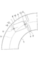
- FIG. 4 is a top view of the construction site showing the asphalt finisher 100 passing through the curved portion (left curve) of the road RD to be constructed.
- the asphalt finisher 100a shows the asphalt finisher 100 at the first time point, which is the start of construction.
- the asphalt finisher 100b indicates the asphalt finisher 100 at the second time point after a predetermined time has elapsed from the first time point.
- the asphalt finisher 100c indicates the asphalt finisher 100 at the third time point after the predetermined time has passed from the second time point
- the asphalt finisher 100d indicates the asphalt at the fourth time point after the predetermined time has passed from the third time point.
- the finisher 100 is shown, and the asphalt finisher 100e shows the asphalt finisher 100 at the fifth time point after a predetermined time has elapsed from the fourth time point.
- FIG. 4 shows the tractor 1, the front screed 30, the left rear screed 31L, and the right rear screed 31R of the asphalt finisher 100 in a simplified manner, while the hopper 2 is not shown. There is.
- the target calculation unit 50a of the controller 50 calculates the target trajectory TPT to be followed by the predetermined point P in the central portion of the tractor 1 at the first time point at the start of construction.
- the predetermined point P is represented by “ ⁇ ”
- the target trajectory TPT is represented by a alternate long and short dash line.
- the target calculation unit 50a refers to the construction design data and derives the center line CP of the road RD based on the left boundary line LP and the right boundary line RP of the road RD to be constructed. Then, the target calculation unit 50a sets the center line CP as the target trajectory TPS to be followed by the predetermined point Q in the central portion of the front screed 30. In the example shown in FIG.
- the predetermined point Q is represented by “ ⁇ ”
- the target trajectory TPS is represented by a broken line.
- the target calculation unit 50a calculates the target trajectory TPT to be followed by the predetermined point P based on known information such as the distance between the rear wheels 5 and the front wheels 6 of the asphalt finisher 100 and the target trajectory TPS. ..
- the left boundary line LP, the right side boundary line RP, the center line CP, the target trajectory TPT that the predetermined point P should follow, and the target trajectory TPS that the predetermined point Q should follow are all numerous. It is derived as a one-dimensional array of position coordinates.
- the position coordinates are, for example, the coordinates in the reference coordinate system.
- the reference coordinate system is, for example, the world geodetic system.
- the origin is set at the center of gravity of the earth
- the X-axis is the intersection of the Greenwich meridian and the equator
- the axis that passes through the origin is the X-axis
- the intersection and the origin of the meridian and the equator at 90 degrees east longitude are passed.
- It is a three-dimensional Cartesian XYZ coordinate system in which the axis to be used is the Y axis and the axis passing through the north pole and the origin is the Z axis.
- the steering control unit 50b of the controller 50 operates the asphalt finisher 100 so that the actual position coordinates of the predetermined point P match one of the position coordinates constituting the target trajectory TPT. Specifically, the steering control unit 50b derives the current position of the predetermined point P in the central portion of the tractor 1 based on the output of the positioning device 51P. Then, when the position of the predetermined point P is located on the right side of the target trajectory TPT, the steering control unit 50b outputs a control command to the steering electromagnetic control valve constituting the steering device 53, and the front wheels A predetermined amount of hydraulic oil is made to flow into the oil chamber on the bottom side of the steering cylinder.
- the asphalt finisher 100 moves to the left while advancing, and the position of the predetermined point P approaches the target trajectory TPT.
- the steering control unit 50b outputs a control command to the steering electromagnetic control valve constituting the steering device 53.
- a predetermined amount of hydraulic oil is made to flow into the oil chamber on the rod side of the front wheel steering cylinder.
- the asphalt finisher 100 moves to the right while advancing, and the position of the predetermined point P approaches the target trajectory TPT.
- the front wheel steering cylinder is configured such that the left steering angle increases as it extends beyond a predetermined length, and the right steering angle increases as it contracts below a predetermined length.
- the controller 50 can position the predetermined point P, which was at the position of the point Pa at the first time point, at the point Pb at the second time point, and can position it at the point Pc at the third time point. It can be positioned at the point Pd at the 4th time point and can be positioned at the point Pe at the 5th time point. As a result, the controller 50 can position the predetermined point Q that was at the position of the point Qa at the first time point at the point Qb at the second time point, can be positioned at the point Qc at the third time point, and can be positioned at the point Qc at the third time point. Can be positioned at the point Qd, and can be positioned at the point Qe at the fifth time point.
- the left rear screed 31L is extended to the left so that its left end surface coincides with the left boundary line LP of the road RD, and the right rear screed 31R has its right end surface on the right side of the road RD. It is extended to the right to match the boundary line RP. Then, the left end surface of the left rear screed 31L moves so as to follow the left boundary line LP, and the right end surface of the right rear screed 31R moves so as to follow the right boundary line RP. Therefore, the controller 50 can match the width of the road RD with the width of the new pavement NP by advancing the tractor 1 so that the predetermined point P in the central portion of the tractor 1 follows the target trajectory TPT. ..
- the controller 50 may expand and contract the rear screed 31 while the asphalt finisher 100 is running.
- the controller 50 may extend the left rear screed 31L to the left when the left end surface of the left rear screed 31L may deviate from the left boundary line LP to the inside of the road RD.
- the controller 50 may extend the right rear screed 31R to the right when the right end surface of the right rear screed 31R may deviate from the right boundary line RP to the inside of the road RD.
- the steering control unit 50b controls the steering of the asphalt finisher 100 when the asphalt finisher 100 is traveling on the curved portion of the road RD, but the asphalt finisher 100 controls the steering of the road RD.
- the steering of the asphalt finisher 100 may be controlled while traveling on the straight portion of the asphalt finisher 100.
- FIG. 5 is a top view of the construction site showing the asphalt finisher 100 passing through the curved portion of the road RD to be constructed.
- FIG. 5 shows the tractor 1, front screed 30, left rear screed 31L, and right rear screed 31R of the asphalt finisher 100 in a simplified manner, while the hopper 2 is illustrated. Is omitted.
- the target calculation unit 50a of the controller 50 derives the center line CP of the road RD to be constructed based on the information acquired by the forward monitoring device 51F.
- the center line CP is represented by a dotted line.
- the target calculation unit 50a derives the left side boundary line LP and the right side boundary line RP of the road RD based on the information acquired by the forward monitoring device 51F, and based on the left side boundary line LP and the right side boundary line RP. Derivation of the center line CP of the road RD.
- the information acquired by the forward monitoring device 51F is, for example, the position and orientation of the step between the curb block and the roadbed BS.
- the target calculation unit 50a derives the current position Pn of the predetermined point P in the central portion of the tractor 1 and the current position Qn of the predetermined point Q in the central portion of the front screed 30. Specifically, the target calculation unit 50a derives the current position Pn of the predetermined point P and the current position Qn of the predetermined point Q based on the output of the positioning device 51P.
- the predetermined point P is represented by “ ⁇ ”
- the predetermined point Q is represented by “ ⁇ ”.
- the target calculation unit 50a calculates the target position Pf as the point where the predetermined point P should reach after the elapse of the predetermined time. Specifically, the target calculation unit 50a calculates the target position Qf as the point where the predetermined point Q should reach after the elapse of the predetermined time based on the construction design data and the current position Pn of the predetermined point P, and the asphalt finisher 100
- the target position Pf is calculated based on known information such as the distance between the rear wheels 5 and the front wheels 6 and the target position Qf. Both the target position Pf and the target position Qf are derived as position coordinates.
- the position coordinates are, for example, the coordinates in the reference coordinate system. In the example shown in FIG. 5, the target position Pf is represented by “ ⁇ ” indicated by the dotted line, and the target position Qf is represented by “ ⁇ ” indicated by the dotted line.
- the steering control unit 50b of the controller 50 operates the asphalt finisher 100 so that the position coordinates of the predetermined point P match the position coordinates of the target position Pf.
- the steering control unit 50b derives the central axis AX of the asphalt finisher 100 based on the output of the positioning device 51P.
- the steering control unit 50b outputs a control command to the steering electromagnetic control valve constituting the steering device 53, and the front wheel steering cylinder.
- a predetermined amount of hydraulic oil is made to flow into the oil chamber on the bottom side of the cylinder.
- the asphalt finisher 100 moves to the left while advancing, and the position of the predetermined point P approaches the target position Pf.
- the steering control unit 50b outputs a control command to the steering electromagnetic control valve constituting the steering device 53 to steer the front wheels.
- a predetermined amount of hydraulic oil is made to flow into the oil chamber on the rod side of the cylinder.
- the asphalt finisher 100 moves to the right while advancing, and the position of the predetermined point P approaches the target position Pf.
- the front wheel steering cylinder is configured such that the left steering angle increases as it extends beyond a predetermined length, and the right steering angle increases as it contracts below a predetermined length.
- the controller 50 can position the predetermined point P at the target position Pf.
- the controller 50 can position the predetermined point Q at the target position Qf.
- the steering control unit 50b may operate the asphalt finisher 100 so that the position coordinates of the predetermined point Q match the position coordinates of the target position Qf. Alternatively, the steering control unit 50b may operate the asphalt finisher 100 so that the predetermined point Q approaches the center line CP of the road RD. In this case, the steering control unit 50b determines whether the predetermined point Q is on the center line CP of the road RD, on the right side of the center line CP, or on the left side of the center line CP at each predetermined control cycle. judge. Then, the steering control unit 50b moves the asphalt finisher 100 to the left side when it is determined to be on the right side, and moves the asphalt finisher 100 to the right side when it is determined to be on the right side.
- the left rear screed 31L is extended to the left so that its left end surface coincides with the left boundary line LP of the road RD, and the right rear screed 31R has its right end surface on the right side of the road RD. It is extended to the right to match the boundary line RP. Then, the left end surface of the left rear screed 31L moves so as to follow the left boundary line LP, and the right end surface of the right rear screed 31R moves so as to follow the right boundary line RP. Therefore, the controller 50 advances the tractor 1 so that the predetermined point P in the central portion of the tractor 1 follows the target position Pf calculated for each predetermined control cycle, thereby increasing the width of the road RD and the new pavement. The width of the body NP can be matched.
- the controller 50 may expand and contract the rear screed 31 while the asphalt finisher 100 is running.
- the controller 50 may extend the left rear screed 31L to the left when the left end surface of the left rear screed 31L may deviate from the left boundary line LP to the inside of the road RD.
- the controller 50 may extend the right rear screed 31R to the right when the right end surface of the right rear screed 31R may deviate from the right boundary line RP to the inside of the road RD.
- the steering control unit 50b controls the steering of the asphalt finisher 100 when the asphalt finisher 100 is traveling on the curved portion of the road RD, but the asphalt finisher 100 controls the steering of the road RD.
- the steering of the asphalt finisher 100 may be controlled while traveling on the straight portion of the asphalt finisher 100.
- FIGS. 6A and 6B are top views of the construction site showing the asphalt finisher 100 passing through the curved portion of the road RD to be constructed.
- FIG. 6A shows the movement of the asphalt finisher 100 when the steering device 53 automatically steers.
- FIG. 6B shows the movement of the asphalt finisher 100 when the manual steering is performed so that the predetermined point P at the central portion of the tractor 1 follows the center line CP of the road RD.
- the predetermined point P in the central portion of the tractor 1 is represented by “ ⁇ ”
- the predetermined point Q in the central portion of the front screed 30 is represented by “ ⁇ ”.
- the predetermined point Q at the central portion of the front screed 30 follows the trajectory PS indicated by the alternate long and short dash line. .. That is, when the asphalt finisher 100 passes through the curved portion of the road RD, the distance between the front end of the right side surface of the tractor 1 and the right boundary line RP of the road RD is the distance between the front end of the left side surface of the tractor 1 and the road RD. The distance between the front end of the right side surface of the front screed 30 and the right side boundary line RP of the road RD is the front end of the left side surface of the front screed 30.
- the driver of the asphalt finisher 100 assumes that when the asphalt finisher 100 passes through the curved portion of the road RD, the asphalt finisher 100 is moved so that the tractor 1 is located at the center in the width direction of the road RD.
- the screed 3 cannot be positioned at the center in the width direction of the road RD.
- the movement of the asphalt finisher 100 is automatically controlled by the steering device 53 so that the predetermined point P follows the target trajectory TPT, the movement of the asphalt finisher 100 is automatically controlled in the central portion of the front screed 30.
- the predetermined point Q follows the center line CP of the road RD indicated by the broken line. That is, when the asphalt finisher 100 passes through the curved portion of the road RD, the distance between the front end of the right side surface of the tractor 1 and the right boundary line RP of the road RD is the distance between the front end of the left side surface of the tractor 1 and the road RD.
- the distance between the front end of the right side surface of the front screed 30 and the right side boundary line RP of the road RD is smaller than the distance between the left side boundary line LP and the front end of the left side surface of the front side screed 30. It changes in a state almost equal to the distance between the road RD and the left boundary line LP of the road RD. Therefore, the pavement material is surely laid in the area inside the curved portion of the road RD, and the pavement material is not laid out of the right boundary line RP of the road RD. That is, the asphalt finisher 100 can match the width of the road RD to be constructed and the width of the new pavement NP even at the curved portion of the road RD.
- the controller 50 moves the screed 3 so that the tractor 1 approaches the end in the width direction of the road RD when the asphalt finisher 100 passes through the curved portion of the road RD. It can be located in the center of the road RD in the width direction.
- the asphalt finisher 100 has the tractor 1, the hopper 2 installed on the front side of the tractor 1 and accepting the pavement material, and the pavement material in the hopper 2 to the rear side of the tractor 1.
- the conveyor CV to be fed
- the pavement SC to spread the pavement material fed by the conveyor CV on the rear side of the tractor 1
- the screed 3 to spread the pavement material spread by the screw SC on the rear side of the screw SC.
- the movement of the tractor 1 is controlled based on the information acquisition device 51 that acquires information on the road to be constructed and the target track TPT or the target position Pf or Qf determined by the information on the road to be constructed acquired by the information acquisition device 51. It is provided with a controller 50 as a control device for the operation.
- the asphalt finisher 100 can appropriately lay a pavement along the road RD to be constructed.
- the controller 50 sets the target track TPT or the target position Pf on the road to be constructed at the curved portion of the road RD to be constructed. It may be configured to be set outside (right side) of the center of the RD (center line CP).
- the target orbit TPT is, for example, a target orbit to be followed by a predetermined point P in the central portion of the tractor 1, and the target position Pf is a point to be reached by the predetermined point P after a lapse of a predetermined time.
- the controller 50 may be configured to set the target track TPT or the target position Pf so that the center in the width direction of the road RD to be constructed coincides with the center in the width direction of the screed 3.
- the target calculation unit 50a of the controller 50 has a target trajectory TPT or a target position so that the trajectory drawn by the predetermined point Q in the central portion of the front screed 30 and the center line CP of the road RD coincide with each other. It may be configured to set Pf.
- the controller 50 can match the width of the road RD with the width of the new pavement NP even when the asphalt finisher 100 passes not only the straight portion of the road RD but also the curved portion.
- the controller 50 may be configured to set the target trajectory TPT or the target position Pf so that at least one end of the screed 3 coincides with the feature.
- the target trajectory TPT or the target position Pf may be set so as to match the RP.
- the target calculation unit 50a of the controller 50 may set the target trajectory TPT or the target position Pf so that the left end portion of the screed 3 and the left boundary line LP of the road RD coincide with each other.
- the target calculation unit 50a of the controller 50 may set the target trajectory TPT or the target position Pf so that the right end portion of the screed 3 and the right boundary line RP of the road RD coincide with each other.
- the controller 50 may be configured to set the target trajectory TPT or the target position Pf based on the distance in the front-rear direction between the predetermined point P as the steering reference point and the screed 3.
- the controller 50 may be configured to set the target trajectory TPT or the target position Pf based on the distance in the front-rear direction between the predetermined point P and the predetermined point Q at the center of the front screed 30.
- the controller 50 may be configured to set the target trajectory TPS or the target position Qf based on the distance in the front-rear direction between the predetermined point P as the steering reference point and the screed 3.
- the controller 50 may be configured to set the target trajectory TPS or the target position Qf based on the distance in the front-rear direction between the predetermined point P and the predetermined point Q in the central portion of the front screed 30.
- the target trajectory TPS is, for example, a target trajectory that the predetermined point Q in the central portion of the front screed 30 should follow, and the target position Qf is a point that the predetermined point Q should reach after the lapse of a predetermined time.
- the controller 50 controls the movement of the tractor 1 by controlling the steering angle of the front wheels 6, and in the case of a crawler-type asphalt finisher, the rotation speeds of the left crawler and the right crawler, respectively. May be configured to control the movement of the tractor 1 by individually controlling the tractor 1.
- the controller 50 paves along the road RD to be constructed by automatically controlling the movement of the asphalt finisher 100 regardless of whether the asphalt finisher 100 is a wheel type asphalt finisher or a crawler type asphalt finisher. You can lay your body properly.
- the controller 50 may be configured to control the movement of the tractor 1 so that the asphalt finisher 100 moves along a preset target trajectory TPT. Specifically, the controller 50 is configured to control the movement of the tractor 1 so that the asphalt finisher 100 moves along the target trajectory TPT set before the asphalt finisher 100 starts traveling. You may. However, the controller 50 may be configured to control the movement of the tractor 1 so that the asphalt finisher 100 moves along the target trajectory TPT calculated in real time.
- the controller 50 can easily and surely appropriately control the movement of the tractor 1.
- the information acquisition device 51 may be an image pickup device or a communication device 51T.
- the imaging device may be a LIDAR, a monocular camera, a stereo camera, a distance image camera, or the like.
- the steering device 53 is configured to expand and contract the front wheel steering cylinder installed near the front axle, but when a hydraulic steering motor is adopted instead of the front wheel steering cylinder. May be configured to rotate the hydraulic steering motor.
- the steering device 53 includes a steering electromagnetic control valve that controls the flow rate of hydraulic oil flowing from the hydraulic pump to the hydraulic steering motor.
- the steering electromagnetic control valve is configured to be able to control the inflow and outflow of hydraulic oil in the hydraulic steering motor according to the rotation of the steering wheel SH (steering wheel) as an operating device.
- the steering electromagnetic control valve is configured to be able to control the inflow and outflow of hydraulic oil in the hydraulic steering motor in response to a control command from the controller 50, regardless of the rotation of the steering wheel SH.
- the steering device 53 may be configured to control an electric motor that automatically rotates the steering wheel SH. In this case, the steering device can automatically control the movement of the asphalt finisher 100 by automatically rotating the steering wheel SH in response to a control command from the controller 50.
- Travel speed sensor 51T Communication device 52 ... In-vehicle display device 53 ... Steering device 100 ... Asphalt finisher AP ... Feature BS ... Roadbed CV ... Conveyor DS ... Automatic steering system NP ... New pavement Body PL ... Pole PV ... Pavement material SC ... Screw SH ... Steering wheel
Abstract
An asphalt finisher (100) comprises: a tractor (1); a hopper (2) installed on the front side of the tractor (1), the hopper receiving paving material; a conveyor (CV) that feeds the paving material inside the hopper (2) to the rear side of the tractor (1); a screw (SC) that spreads out the paving material fed by the conveyor (CV) on the rear side of the tractor; a screed (3) that evens the paving material spread out by the screw (SC) on the rear side of the screw (SC); an information acquisition device (51) that acquires information relating to a road to be constructed; and a controller (50) that controls the movement of the tractor (1) on the basis of a target position (Pf) or (Qf), or of a target trajectory (TPT) decided according to the information acquired by the information acquisition device (51) relating to the road to be constructed.
Description
本開示は、アスファルトフィニッシャに関する。
This disclosure relates to an asphalt finisher.
従来、トラクタと、トラクタの前側に設置されて舗装材を受け入れるホッパと、ホッパ内の舗装材をトラクタの後側へ給送するコンベアと、コンベアにより給送された舗装材をトラクタの後側で敷き拡げるスクリュと、スクリュにより敷き拡げられた舗装材をスクリュの後側で敷き均すスクリードとを備えたアスファルトフィニッシャが知られている(特許文献1参照。)。
Conventionally, the tractor, the hopper installed on the front side of the tractor to receive the pavement material, the conveyor that feeds the pavement material in the hopper to the rear side of the tractor, and the pavement material fed by the conveyor on the rear side of the tractor. An asphalt finisher having a screw that is spread and a screed that spreads the pavement material spread by the screw on the rear side of the screw is known (see Patent Document 1).
アスファルトフィニッシャの運転者は、通常、トラクタに取り付けられたガイド棒(指針棒)を利用し、敷設される舗装体の幅方向の端面が、施工対象の道路における段差に沿って延びるようにアスファルトフィニッシャを走行させる。すなわち、運転者は、スクリードの幅方向の端面と段差が形成する段差面とが略平行となる状態を維持しながらアスファルトフィニッシャを走行させる。なお、施工対象の道路における段差は、例えば、縁石と路盤との間の段差、既設の舗装体と路盤との間の段差、舗装用型枠と路盤との間の段差、又は、古い舗装体を切削したときにできる段差等である。
The driver of the asphalt finisher usually uses a guide rod (pointer rod) attached to the tractor so that the widthwise end face of the pavement to be laid extends along the step on the road to be constructed. To run. That is, the driver runs the asphalt finisher while maintaining a state in which the end surface in the width direction of the screed and the step surface formed by the step are substantially parallel. The steps on the road to be constructed include, for example, a step between the curb and the roadbed, a step between the existing pavement and the roadbed, a step between the pavement formwork and the roadbed, or an old pavement. It is a step etc. that is created when cutting.
しかしながら、施工対象の道路が湾曲している場合、運転者は、ガイド棒を利用するだけでは、敷設される舗装体の幅方向の端面を段差に沿わせることができない。トラクタの後側に位置するスクリードの中央部における所定点が描く軌跡は、トラクタの中央部における所定点が描く軌跡を辿ることなく、カーブの外側に膨らんでしまうためである。
However, when the road to be constructed is curved, the driver cannot make the end face in the width direction of the pavement to be laid along the step only by using the guide rod. This is because the locus drawn by the predetermined point in the central portion of the screed located behind the tractor bulges outside the curve without following the locus drawn by the predetermined point in the central portion of the tractor.
上述に鑑み、施工対象の道路に沿って舗装体を適切に敷設できるアスファルトフィニッシャを提供することが望まれる。
In view of the above, it is desirable to provide an asphalt finisher that can appropriately lay a pavement along the road to be constructed.
本発明の実施形態に係るアスファルトフィニッシャは、トラクタと、前記トラクタの前側に設置されて舗装材を受け入れるホッパと、前記ホッパ内の舗装材を前記トラクタの後側へ給送するコンベアと、前記コンベアにより給送された前記舗装材を前記トラクタの後側で敷き拡げるスクリュと、前記スクリュにより敷き拡げられた前記舗装材を前記スクリュの後側で敷き均すスクリードと、施工対象の道路に関する情報を取得する情報取得装置と、前記情報取得装置が取得した施工対象の道路に関する情報によって決まる目標軌道又は目標位置に基づいて前記トラクタの動きを制御する制御装置と、を備える。
The asphalt finisher according to the embodiment of the present invention includes a tractor, a hopper installed on the front side of the tractor to receive the pavement material, a conveyor for feeding the pavement material in the hopper to the rear side of the tractor, and the conveyor. A screw that spreads the pavement material supplied by the tractor on the rear side of the tractor, a screed that spreads the pavement material spread by the screw on the rear side of the screw, and information on the road to be constructed. It includes an information acquisition device to be acquired and a control device that controls the movement of the tractor based on a target track or a target position determined by the information about the road to be constructed acquired by the information acquisition device.
上述の手段により、施工対象の道路に沿って舗装体を適切に敷設できるアスファルトフィニッシャが提供される。
By the above means, an asphalt finisher that can appropriately lay a pavement along the road to be constructed is provided.
図1は、本発明の実施形態に係るアスファルトフィニッシャ100の側面図である。図2はアスファルトフィニッシャ100の上面図である。本実施形態では、アスファルトフィニッシャ100は、ホイール式アスファルトフィニッシャであり、主に、トラクタ1、ホッパ2、及びスクリード3で構成されている。以下では、トラクタ1から見たホッパ2の方向(+X方向)を前方とし、トラクタ1から見たスクリード3の方向(-X方向)を後方とする。
FIG. 1 is a side view of the asphalt finisher 100 according to the embodiment of the present invention. FIG. 2 is a top view of the asphalt finisher 100. In the present embodiment, the asphalt finisher 100 is a wheel-type asphalt finisher, and is mainly composed of a tractor 1, a hopper 2, and a screed 3. In the following, the direction of the hopper 2 as seen from the tractor 1 (+ X direction) is the front, and the direction of the screed 3 as seen from the tractor 1 (−X direction) is the rear.
トラクタ1は、アスファルトフィニッシャ100を移動させるための機構である。本実施形態では、トラクタ1は、後輪走行用油圧モータを用いて後輪5を回転させ、且つ、前輪走行用油圧モータを用いて前輪6を回転させてアスファルトフィニッシャ100を移動させる。後輪走行用油圧モータ及び前輪走行用油圧モータは油圧ポンプから作動油の供給を受けて回転する。但し、前輪6は従動輪であってもよい。
The tractor 1 is a mechanism for moving the asphalt finisher 100. In the present embodiment, the tractor 1 uses the rear wheel traveling hydraulic motor to rotate the rear wheels 5, and the front wheel traveling hydraulic motor to rotate the front wheels 6 to move the asphalt finisher 100. The rear wheel traveling hydraulic motor and the front wheel traveling hydraulic motor rotate by receiving the supply of hydraulic oil from the hydraulic pump. However, the front wheel 6 may be a driven wheel.
アスファルトフィニッシャ100は、クローラ式アスファルトフィニッシャであってもよい。この場合、後輪5及び前輪6の組み合わせは左クローラ及び右クローラの組み合わせで置き換えられる。
The asphalt finisher 100 may be a crawler type asphalt finisher. In this case, the combination of the rear wheels 5 and the front wheels 6 is replaced by the combination of the left crawler and the right crawler.
コントローラ50は、アスファルトフィニッシャ100を制御する制御装置である。本実施形態では、コントローラ50は、CPU、揮発性記憶装置、及び不揮発性記憶装置等を含むマイクロコンピュータで構成され、トラクタ1に搭載されている。コントローラ50の各機能は、不揮発性記憶装置に記憶されているプログラムをCPUが実行することで実現される。但し、コントローラ50の各機能は、ソフトウェアで実現されるばかりでなく、ハードウェアで実現されてもよく、ハードウェアとソフトウェアの組み合わせによって実現されてもよい。
The controller 50 is a control device that controls the asphalt finisher 100. In the present embodiment, the controller 50 is composed of a microcomputer including a CPU, a volatile storage device, a non-volatile storage device, and the like, and is mounted on the tractor 1. Each function of the controller 50 is realized by the CPU executing a program stored in the non-volatile storage device. However, each function of the controller 50 is not only realized by software, but may be realized by hardware, or may be realized by a combination of hardware and software.
ホッパ2は、舗装材を受け入れるための機構である。本実施形態では、ホッパ2は、トラクタ1の前側に設置され、ホッパシリンダによって車幅方向(Y軸方向)に開閉できるように構成されている。アスファルトフィニッシャ100は、通常、ホッパ2が全開状態のときにダンプトラックの荷台から舗装材(例えばアスファルト混合物である。)を受け入れる。ダンプトラックは、舗装材を運搬する運搬車両の一例である。図1及び図2はホッパ2が全開状態であることを示す。ホッパ2内の舗装材が減少するとホッパ2が閉じられ、ホッパ2の内壁付近にあった舗装材がホッパ2の中央部に集められる。ホッパ2の中央部にあるコンベアCVがトラクタ1の後側に舗装材を給送できるようにするためである。トラクタ1の後側に給送された舗装材は、スクリュSCによってトラクタ1の後側且つスクリード3の前側で車幅方向に敷き拡げられる。本実施形態では、スクリュSCは、エクステンションスクリュが左右に連結された状態にある。図1及び図2は、ホッパ2内にある舗装材の図示を省略し、スクリュSCによって敷き拡げられた舗装材PVを粗いドットパターンで示し、スクリード3によって敷き均された新設舗装体NPを細かいドットパターンで示している。
Hopper 2 is a mechanism for accepting pavement materials. In the present embodiment, the hopper 2 is installed on the front side of the tractor 1 and is configured to be opened and closed in the vehicle width direction (Y-axis direction) by the hopper cylinder. The asphalt finisher 100 normally receives a pavement material (eg, an asphalt mixture) from the dump truck bed when the hopper 2 is fully open. A dump truck is an example of a transport vehicle that transports pavement materials. 1 and 2 show that the hopper 2 is in the fully open state. When the amount of pavement material in the hopper 2 decreases, the hopper 2 is closed, and the pavement material near the inner wall of the hopper 2 is collected in the central portion of the hopper 2. This is so that the convair CV in the central portion of the hopper 2 can supply the pavement material to the rear side of the tractor 1. The pavement material fed to the rear side of the tractor 1 is spread in the vehicle width direction by the screw SC on the rear side of the tractor 1 and the front side of the screed 3. In the present embodiment, the screw SC is in a state where the extension screws are connected to the left and right. In FIGS. 1 and 2, the illustration of the pavement material in the hopper 2 is omitted, the pavement material PV spread by the screw SC is shown by a coarse dot pattern, and the new pavement body NP spread by the screed 3 is fine. It is shown by a dot pattern.
スクリード3は、舗装材PVを敷き均すための機構である。本実施形態では、スクリード3は、前側スクリード30及び後側スクリード31を含む。前側スクリード30は、左前側スクリード30L及び右前側スクリード30Rを含む。後側スクリード31は、車幅方向に伸縮可能なスクリードであり、左後側スクリード31L及び右後側スクリード31Rを含む。但し、後側スクリード31は、前側スクリード30の左右に連結される固定幅スクリードであってもよい。また、スクリード3は、トラクタ1によって牽引される浮動スクリードであり、レベリングアーム3Aを介してトラクタ1に連結されている。レベリングアーム3Aは、トラクタ1の左側に配置される左レベリングアーム3ALと、トラクタ1の右側に配置される右レベリングアーム3ARとを含む。
Screed 3 is a mechanism for spreading the pavement material PV. In this embodiment, the screed 3 includes a front screed 30 and a rear screed 31. The front screed 30 includes a left front screed 30L and a right front screed 30R. The rear screed 31 is a screed that can be expanded and contracted in the vehicle width direction, and includes a left rear screed 31L and a right rear screed 31R. However, the rear screed 31 may be a fixed width screed connected to the left and right of the front screed 30. Further, the screed 3 is a floating screed towed by the tractor 1 and is connected to the tractor 1 via a leveling arm 3A. The leveling arm 3A includes a left leveling arm 3AL arranged on the left side of the tractor 1 and a right leveling arm 3AR arranged on the right side of the tractor 1.
スクリード3の前部にはモールドボード43が取り付けられている。モールドボード43は、スクリード3の前方に滞留する舗装材PVの量を調整できるように構成されている。舗装材PVは、モールドボード43の下端と路盤BSとの間の隙間を通ってスクリード3の下に至る。
A mold board 43 is attached to the front part of the screed 3. The mold board 43 is configured so that the amount of pavement material PV staying in front of the screed 3 can be adjusted. The pavement material PV passes under the screed 3 through the gap between the lower end of the mold board 43 and the roadbed BS.
トラクタ1には、情報取得装置51、車載表示装置52、及び操舵装置53が取り付けられている。
An information acquisition device 51, an in-vehicle display device 52, and a steering device 53 are attached to the tractor 1.
情報取得装置51は、施工対象の道路に関する情報を取得し、取得した情報をコントローラ50に対して出力できるように構成されている。施工対象の道路に関する情報は、例えば、道路の幅、緩和区間(クロソイド区間)における曲率の変化、及び円弧区間における曲率等を含む。本実施形態では、情報取得装置51は、前方監視装置51F、後方監視装置51B、走行速度センサ51S、測位装置51P、及び通信装置51Tを含む。
The information acquisition device 51 is configured to acquire information about the road to be constructed and output the acquired information to the controller 50. Information about the road to be constructed includes, for example, the width of the road, the change in curvature in the relaxation section (clothoid section), the curvature in the arc section, and the like. In the present embodiment, the information acquisition device 51 includes a front monitoring device 51F, a rear monitoring device 51B, a traveling speed sensor 51S, a positioning device 51P, and a communication device 51T.
前方監視装置51Fは、アスファルトフィニッシャ100の前方を監視できるように構成されている。本実施形態では、前方監視装置51Fは、トラクタ1の前方にある監視範囲RFを監視するLIDARであり、トラクタ1の中央部に取り付けられている。トラクタ1の中央部は、例えば、ホッパ2の後側にあるエンジン室を覆うカバーの前端中央部である。但し、前方監視装置51Fは、アスファルトフィニッシャ100の他の部位に取り付けられていてもよく、複数のLIDARで構成されていてもよい。複数のLIDARで構成される場合、前方監視装置51Fは、互いに重複しない複数の監視範囲を同時に監視できる。この場合、複数のLIDARは、トラクタ1の前端右側部に取り付けられた右前LIDARと、トラクタ1の前端左側部に取り付けられた左前LIDARとを含んでいてもよい。また、LIDARは、ブラケット又はポール等を介してトラクタ1に取り付けられていてもよい。
The front monitoring device 51F is configured to be able to monitor the front of the asphalt finisher 100. In the present embodiment, the forward monitoring device 51F is a lidar that monitors the monitoring range RF in front of the tractor 1, and is attached to the central portion of the tractor 1. The central portion of the tractor 1 is, for example, the central portion of the front end of the cover covering the engine chamber on the rear side of the hopper 2. However, the forward monitoring device 51F may be attached to another part of the asphalt finisher 100, or may be composed of a plurality of lidars. When composed of a plurality of lidars, the forward monitoring device 51F can simultaneously monitor a plurality of monitoring ranges that do not overlap each other. In this case, the plurality of LIDARs may include a right front LIDAR attached to the front right side portion of the tractor 1 and a left front LIDAR attached to the front end left side portion of the tractor 1. Further, the lidar may be attached to the tractor 1 via a bracket, a pole, or the like.
後方監視装置51Bは、アスファルトフィニッシャ100の後方を監視できるように構成されている。本実施形態では、後方監視装置51Bは、スクリード3の後方にある監視範囲RBを監視するLIDARであり、手摺りとして機能するガイドレール1Gに取り付けられている。但し、後方監視装置51Bは、運転席1Sの下部に取り付けられていてもよく、アスファルトフィニッシャ100の他の部位に取り付けられていてもよい。また、後方監視装置51Bは、複数のLIDARで構成されていてもよい。複数のLIDARで構成される場合、後方監視装置51Bは、互いに重複しない複数の監視範囲を同時に監視できる。この場合、複数のLIDARは、トラクタ1の後端右側部に取り付けられた右後LIDARと、トラクタ1の後端左側部に取り付けられた左後LIDARとを含んでいてもよい。また、LIDARは、ブラケット又はポール等を介してトラクタ1に取り付けられていてもよい。
The rear monitoring device 51B is configured to be able to monitor the rear of the asphalt finisher 100. In the present embodiment, the rear monitoring device 51B is a lidar that monitors the monitoring range RB behind the screed 3, and is attached to a guide rail 1G that functions as a handrail. However, the rear monitoring device 51B may be attached to the lower part of the driver's seat 1S, or may be attached to another part of the asphalt finisher 100. Further, the rear monitoring device 51B may be composed of a plurality of lidars. When composed of a plurality of lidars, the rear monitoring device 51B can simultaneously monitor a plurality of monitoring ranges that do not overlap each other. In this case, the plurality of lidars may include a right rear lidar attached to the right rear end of the tractor 1 and a left rear lidar attached to the left rear end of the tractor 1. Further, the lidar may be attached to the tractor 1 via a bracket, a pole, or the like.
情報取得装置51は、アスファルトフィニッシャ100の側方を監視できるように構成される側方監視装置を含んでいてもよい。この場合、側方監視装置は、左側方監視装置及び右側方監視装置を含んでいてもよい。左側方監視装置は、例えば、トラクタ1の左方にある監視範囲を監視するLIDARとして、後輪5よりも前側でトラクタ1の上面の左端部に取り付けられてもよい。右側方監視装置は、例えば、トラクタ1の右方にある監視範囲を監視するLIDARとして、後輪5よりも前側でトラクタ1の上面の右端部に取り付けられてもよい。
The information acquisition device 51 may include a side monitoring device configured to be able to monitor the side of the asphalt finisher 100. In this case, the side monitoring device may include a left side monitoring device and a right side monitoring device. The left side monitoring device may be attached to the left end portion of the upper surface of the tractor 1 on the front side of the rear wheel 5 as a lidar for monitoring the monitoring range on the left side of the tractor 1, for example. The right side monitoring device may be attached to the right end portion of the upper surface of the tractor 1 on the front side of the rear wheel 5 as a lidar for monitoring the monitoring range on the right side of the tractor 1, for example.
LIDARは、例えば、監視範囲内にある多数の点とLIDARとの間の距離を測定できるように構成されている。但し、前方監視装置51F及び後方監視装置51Bの少なくとも一方は、単眼カメラ、ステレオカメラ、ミリ波レーダ、レーザレーダ、レーザスキャナ、距離画像カメラ、又はレーザレンジファインダ等であってもよい。側方監視装置についても同様である。
LIDAR is configured so that, for example, the distance between a large number of points within the monitoring range and LIDAR can be measured. However, at least one of the front monitoring device 51F and the rear monitoring device 51B may be a monocular camera, a stereo camera, a millimeter wave radar, a laser radar, a laser scanner, a range image camera, a laser range finder, or the like. The same applies to the side monitoring device.
前方監視装置51Fの監視範囲RFは、望ましくは、路盤BSと路盤BSの外側にある地物APとを含む。施工対象の道路の幅に関する情報を取得できるようにするためである。側方監視装置の監視範囲についても同様である。本実施形態では、監視範囲RFは、路盤BSの幅より大きい幅を有する。地物APはL形側溝ブロックである。地物APは、舗装用型枠、縁石ブロック、又は既設舗装体等であってもよい。
The monitoring range RF of the forward monitoring device 51F preferably includes the roadbed BS and the feature AP outside the roadbed BS. This is so that information on the width of the road to be constructed can be obtained. The same applies to the monitoring range of the side monitoring device. In the present embodiment, the monitoring range RF has a width larger than the width of the roadbed BS. The feature AP is an L-shaped gutter block. The feature AP may be a pavement formwork, a curb block, an existing pavement, or the like.
後方監視装置51Bの監視範囲RBは、望ましくは、新設舗装体NPと新設舗装体NPの外側にある地物APとを含む。新設舗装体NPの幅に関する情報を取得できるようにするためである。本実施形態では、監視範囲RBは、新設舗装体NPの幅より大きい幅を有する。
The monitoring range RB of the rear monitoring device 51B preferably includes the new pavement NP and the feature AP outside the new pavement NP. This is so that information on the width of the new pavement NP can be obtained. In the present embodiment, the monitoring range RB has a width larger than the width of the newly constructed pavement NP.
走行速度センサ51Sは、アスファルトフィニッシャ100の走行速度を検出できるように構成されている。本実施形態では、走行速度センサ51Sは、車輪速センサであり、後輪5の回転角速度及び回転角度、ひいては、アスファルトフィニッシャ100の走行速度及び走行距離を検出できるように構成されている。
The traveling speed sensor 51S is configured to be able to detect the traveling speed of the asphalt finisher 100. In the present embodiment, the traveling speed sensor 51S is a wheel speed sensor, and is configured to be able to detect the rotational angular velocity and rotational angle of the rear wheels 5, and thus the traveling speed and traveling distance of the asphalt finisher 100.
測位装置51Pは、アスファルトフィニッシャ100の位置を計測できるように構成されている。本実施形態では、測位装置51Pは、GNSSコンパスであり、アスファルトフィニッシャ100の位置及び姿勢を計測できるように構成されている。測位装置51PとしてのGNSSコンパスは、図1及び図2に示すように、左レベリングアーム3ALの後端部から鉛直上方に延びるポールPLの上端に取り付けられた左GNSS受信機51PLと、右レベリングアーム3ARの後端部から鉛直上方に延びるポールPL(不可視)の上端に取り付けられた右GNSS受信機51PRとを含む。
The positioning device 51P is configured to be able to measure the position of the asphalt finisher 100. In the present embodiment, the positioning device 51P is a GNSS compass and is configured to be able to measure the position and orientation of the asphalt finisher 100. As shown in FIGS. 1 and 2, the GNSS compass as the positioning device 51P includes a left GNSS receiver 51PL attached to the upper end of a pole PL extending vertically upward from the rear end of the left leveling arm 3AL and a right leveling arm. Includes a right GNSS receiver 51PR attached to the top of a pole PL (invisible) that extends vertically upward from the rear end of the 3AR.
但し、測位装置51Pは、トータルステーションであってもよい。この場合、ポールPLの先端には、トータルステーションのターゲットとなる反射プリズムが取り付けられる。アスファルトフィニッシャ100の周囲に設置されているトータルステーションの本体は、無線通信を介してコントローラ50に接続される。すなわち、トータルステーションの本体は、導き出したターゲットの位置に関する情報をコントローラ50に送信する。
However, the positioning device 51P may be a total station. In this case, a reflecting prism that is the target of the total station is attached to the tip of the pole PL. The main body of the total station installed around the asphalt finisher 100 is connected to the controller 50 via wireless communication. That is, the main body of the total station transmits information regarding the derived target position to the controller 50.
通信装置51Tは、アスファルトフィニッシャ100とアスファルトフィニッシャ100の外部にある機器との間の通信を制御できるように構成されている。本実施形態では、通信装置51Tは、運転席1Sの前方に設置され、移動体通信網、近距離無線通信網、又は衛星通信網等を介した通信を制御できるように構成されている。
The communication device 51T is configured to be able to control communication between the asphalt finisher 100 and a device outside the asphalt finisher 100. In the present embodiment, the communication device 51T is installed in front of the driver's seat 1S and is configured to be able to control communication via a mobile communication network, a short-range wireless communication network, a satellite communication network, or the like.
情報取得装置51は、アスファルトフィニッシャ100の操舵角を検出できるように構成された操舵角センサ、及び、後側スクリード31の伸縮量を検出して舗装幅を算出できるように構成された舗装幅センサ等を含んでいてもよい。
The information acquisition device 51 includes a steering angle sensor configured to detect the steering angle of the asphalt finisher 100, and a pavement width sensor configured to detect the amount of expansion and contraction of the rear screed 31 and calculate the pavement width. Etc. may be included.
また、情報取得装置51は、施工現場に設置された監視装置、又は、アスファルトフィニッシャ100の上空を飛行する飛行体に取り付けられた監視装置を含んでいてもよい。施工現場に設置された監視装置は、例えば、施工対象の道路に沿って設置されたポールの先端に取り付けられたLIDAR又は単眼カメラ等である。飛行体に取り付けられた監視装置は、例えば、マルチコプタ(ドローン)又は飛行船等に取り付けられたLIDAR又は単眼カメラ等である。
Further, the information acquisition device 51 may include a monitoring device installed at the construction site or a monitoring device attached to an air vehicle flying over the asphalt finisher 100. The monitoring device installed at the construction site is, for example, a LIDAR or a monocular camera attached to the tip of a pole installed along the road to be constructed. The monitoring device attached to the air vehicle is, for example, a multicopter (drone), a lidar attached to an airship, or a monocular camera.
車載表示装置52は、アスファルトフィニッシャ100に関する情報を表示できるように構成されている。本実施形態では、車載表示装置52は、運転席1Sの前方に設置されている液晶ディスプレイである。但し、車載表示装置52は、スクリード3の左端部及び右端部の少なくとも一方に設置されていてもよい。
The in-vehicle display device 52 is configured to be able to display information about the asphalt finisher 100. In the present embodiment, the vehicle-mounted display device 52 is a liquid crystal display installed in front of the driver's seat 1S. However, the vehicle-mounted display device 52 may be installed at at least one of the left end portion and the right end portion of the screed 3.
操舵装置53は、アスファルトフィニッシャ100の操舵を制御できるように構成されている。本実施形態では、操舵装置53は、フロントアクスルの近くに設置された前輪操舵シリンダを伸縮させるように構成されている。具体的には、操舵装置53は、油圧ポンプから前輪操舵シリンダに流れる作動油の流量、及び、前輪操舵シリンダから排出される作動油の流量を制御する操舵用電磁制御弁を含む。操舵用電磁制御弁は、操作装置としてのステアリングホイールSH(ハンドル)の回転に応じて前輪操舵シリンダにおける作動油の流出入を制御できるように構成されている。また、操舵用電磁制御弁は、コントローラ50からの制御指令に応じ、ステアリングホイールSHの回転とは無関係に、前輪操舵シリンダにおける作動油の流出入を制御できるように構成されている。すなわち、コントローラ50は、運転者によるステアリングホイールSHの操作の有無とは無関係に、アスファルトフィニッシャ100の操舵を制御できる。
The steering device 53 is configured to be able to control the steering of the asphalt finisher 100. In the present embodiment, the steering device 53 is configured to expand and contract the front wheel steering cylinder installed near the front axle. Specifically, the steering device 53 includes a steering electromagnetic control valve that controls the flow rate of the hydraulic oil flowing from the hydraulic pump to the front wheel steering cylinder and the flow rate of the hydraulic oil discharged from the front wheel steering cylinder. The steering electromagnetic control valve is configured to be able to control the inflow and outflow of hydraulic oil in the front wheel steering cylinder according to the rotation of the steering wheel SH (steering wheel) as an operating device. Further, the steering electromagnetic control valve is configured to be able to control the inflow and outflow of hydraulic oil in the front wheel steering cylinder in response to a control command from the controller 50, regardless of the rotation of the steering wheel SH. That is, the controller 50 can control the steering of the asphalt finisher 100 regardless of whether or not the driver operates the steering wheel SH.
アスファルトフィニッシャ100がクローラ式アスファルトフィニッシャである場合、操舵装置53は、左右一対のクローラを別々に制御できるように構成される。具体的には、操舵装置53は、油圧ポンプから左クローラを回転させるための左走行用油圧モータに流れる作動油の流量を制御する左電磁制御弁と、油圧ポンプから右クローラを回転させるための右走行用油圧モータに流れる作動油の流量を制御する右電磁制御弁とを含む。そして、左電磁制御弁は、左クローラを操作するための操作装置である左操作レバーの操作量(傾斜角)に応じて左走行用油圧モータにおける作動油の流出入を制御できるように構成される。また、左電磁制御弁は、コントローラ50からの制御指令に応じ、運転者による左操作レバーの操作の有無とは無関係に、左走行用油圧モータにおける作動油の流出入を制御できるように構成される。同様に、右電磁制御弁は、右クローラを操作するための操作装置である右操作レバーの操作量(傾斜角)に応じて右走行用油圧モータにおける作動油の流出入を制御できるように構成される。また、右電磁制御弁は、コントローラ50からの制御指令に応じ、運転者による右操作レバーの操作の有無とは無関係に、右走行用油圧モータにおける作動油の流出入を制御できるように構成される。
When the asphalt finisher 100 is a crawler type asphalt finisher, the steering device 53 is configured to be able to control a pair of left and right crawlers separately. Specifically, the steering device 53 includes a left electromagnetic control valve that controls the flow rate of hydraulic oil flowing from the hydraulic pump to the left traveling hydraulic motor for rotating the left crawler, and a left electromagnetic control valve for rotating the right crawler from the hydraulic pump. Includes a right electromagnetic control valve that controls the flow rate of hydraulic oil flowing through the right-running hydraulic motor. The left electromagnetic control valve is configured to be able to control the inflow and outflow of hydraulic oil in the left traveling hydraulic motor according to the operating amount (tilt angle) of the left operating lever, which is an operating device for operating the left crawler. NS. Further, the left electromagnetic control valve is configured to be able to control the inflow and outflow of hydraulic oil in the left traveling hydraulic motor in response to a control command from the controller 50, regardless of whether or not the driver operates the left operating lever. NS. Similarly, the right electromagnetic control valve is configured to be able to control the inflow and outflow of hydraulic oil in the right traveling hydraulic motor according to the operating amount (tilt angle) of the right operating lever, which is an operating device for operating the right crawler. Will be done. Further, the right electromagnetic control valve is configured to be able to control the inflow and outflow of hydraulic oil in the right traveling hydraulic motor in response to a control command from the controller 50, regardless of whether or not the driver operates the right operating lever. NS.
次に、図3を参照し、アスファルトフィニッシャ100に搭載される自動操舵システムDSの構成例について説明する。図3は、自動操舵システムDSの構成例を示すブロック図である。
Next, with reference to FIG. 3, a configuration example of the automatic steering system DS mounted on the asphalt finisher 100 will be described. FIG. 3 is a block diagram showing a configuration example of the automatic steering system DS.
自動操舵システムDSは、主に、コントローラ50、前方監視装置51F、後方監視装置51B、走行速度センサ51S、測位装置51P、通信装置51T、車載表示装置52、及び操舵装置53等で構成されている。
The automatic steering system DS is mainly composed of a controller 50, a front monitoring device 51F, a rear monitoring device 51B, a traveling speed sensor 51S, a positioning device 51P, a communication device 51T, an in-vehicle display device 52, a steering device 53, and the like. ..
図3に示す例では、コントローラ50は、機能ブロックとして目標算出部50a、操舵制御部50b、及び表示制御部50cを含む。
In the example shown in FIG. 3, the controller 50 includes a target calculation unit 50a, a steering control unit 50b, and a display control unit 50c as functional blocks.
目標算出部50aは、操舵制御部50bによって利用される目標を算出できるように構成されている。操舵制御部50bによって利用される目標は、例えば、アスファルトフィニッシャ100上の所定点が描くべき軌道としての目標軌道である。所定点は、アスファルトフィニッシャ100の所定部位に予め対応付けられた点であり、操舵基準点又は制御基準点とも称される。但し、所定点は、アスファルトフィニッシャ100の所定部位に動的に対応付けられる点であってもよい。目標軌道は、厳密には、多数の目標位置の一次元配列である。目標位置は、アスファルトフィニッシャ100上の所定点が到達すべき地点である。或いは、操舵制御部50bによって利用される目標は、所定時間経過後にアスファルトフィニッシャ100上の所定点が到達すべき地点としての目標位置であってもよい。所定時間は、例えば、数ミリ秒、数十ミリ秒、数百ミリ秒、又は数秒である。
The target calculation unit 50a is configured to be able to calculate the target used by the steering control unit 50b. The target used by the steering control unit 50b is, for example, a target trajectory as a trajectory to be drawn by a predetermined point on the asphalt finisher 100. The predetermined point is a point associated with a predetermined portion of the asphalt finisher 100 in advance, and is also referred to as a steering reference point or a control reference point. However, the predetermined point may be a point that is dynamically associated with the predetermined portion of the asphalt finisher 100. Strictly speaking, the target trajectory is a one-dimensional array of a large number of target positions. The target position is a point to be reached by a predetermined point on the asphalt finisher 100. Alternatively, the target used by the steering control unit 50b may be a target position as a point to be reached by a predetermined point on the asphalt finisher 100 after a lapse of a predetermined time. The predetermined time is, for example, several milliseconds, several tens of milliseconds, several hundred milliseconds, or several seconds.
本実施形態では、目標算出部50aは、例えば、施工設計データ等の施工対象の道路に関する情報に基づき、トラクタ1の中央部における所定点が辿るべき目標軌道を算出する。この場合、目標軌道は、典型的には、アスファルトフィニッシャ100の走行が開始される前に算出される。そのため、目標軌道は、アスファルトフィニッシャ100の外部にある管理センタに設置されたサーバ等で算出された後、通信を介してコントローラ50に送信されてもよい。なお、所定点は、トラクタ1の中央部に設定された点ではなく、ホッパ2の前端部の中央部に設定された点であってもよい。また、ホイール式アスファルトフィニッシャの場合には、所定点は、左前輪の位置に設定された点であってもよく、右前輪の位置に設定された点であってもよく、前輪軸の中央部に設定された点であってもよい。
In the present embodiment, the target calculation unit 50a calculates the target trajectory that the predetermined point in the central portion of the tractor 1 should follow based on, for example, information about the road to be constructed such as construction design data. In this case, the target track is typically calculated before the asphalt finisher 100 starts running. Therefore, the target trajectory may be calculated by a server or the like installed in the management center outside the asphalt finisher 100, and then transmitted to the controller 50 via communication. The predetermined point may not be a point set at the central portion of the tractor 1, but may be a point set at the central portion of the front end portion of the hopper 2. Further, in the case of a wheel-type asphalt finisher, the predetermined point may be a point set at the position of the left front wheel or a point set at the position of the right front wheel, and may be a central portion of the front wheel axle. It may be a point set to.
目標算出部50aは、所定時間経過後にトラクタ1の中央部における所定点が到達すべき地点としての目標位置を算出してもよい。この場合、目標位置は、アスファルトフィニッシャ100の走行中に、所定の制御周期で繰り返し算出される。例えば、目標算出部50aは、前方監視装置51Fが取得した情報に基づき、トラクタ1の中央部における所定点の現在位置よりも所定距離だけ前方に位置する施工対象の道路の幅方向の中心点を目標位置として算出してもよい。所定距離は、例えば、数センチメートル又は数十センチメートルである。この場合、目標算出部50aは、施工設計データを取得することなく、目標位置を算出できる。但し、目標算出部50aは、施工設計データと前方監視装置51Fが取得した情報とに基づき、目標位置を算出してもよい。例えば、目標算出部50aは、施工設計データに基づいて算出された目標位置を、前方監視装置51Fが取得した情報に基づいて補正してもよい。また、目標算出部50aは、後方監視装置51Bが取得した情報を利用してもよい。
The target calculation unit 50a may calculate the target position as a point at which the predetermined point in the central portion of the tractor 1 should reach after the lapse of a predetermined time. In this case, the target position is repeatedly calculated in a predetermined control cycle while the asphalt finisher 100 is running. For example, the target calculation unit 50a determines the center point in the width direction of the road to be constructed, which is located a predetermined distance ahead of the current position of the predetermined point in the central portion of the tractor 1 based on the information acquired by the forward monitoring device 51F. It may be calculated as a target position. The predetermined distance is, for example, several centimeters or several tens of centimeters. In this case, the target calculation unit 50a can calculate the target position without acquiring the construction design data. However, the target calculation unit 50a may calculate the target position based on the construction design data and the information acquired by the front monitoring device 51F. For example, the target calculation unit 50a may correct the target position calculated based on the construction design data based on the information acquired by the forward monitoring device 51F. Further, the target calculation unit 50a may use the information acquired by the rear monitoring device 51B.
操舵制御部50bは、操作装置に対する操作とは無関係に、アスファルトフィニッシャ100の操舵を自動制御できるように構成されている。
The steering control unit 50b is configured to be able to automatically control the steering of the asphalt finisher 100 regardless of the operation on the operating device.
本実施形態では、操舵制御部50bは、目標算出部50aが算出した目標軌道を、トラクタ1の中央部における所定点が辿るように、操舵装置53に対して制御指令を出力する。具体的には、操舵制御部50bは、測位装置51Pの出力に基づき、トラクタ1の中央部における所定点の現在位置を導き出す。そして、所定点が目標軌道から右方向に逸脱していると判定した場合、操舵制御部50bは、アスファルトフィニッシャ100が左方に移動するように、操舵装置53に対して制御指令を出力する。同様に、所定点が目標軌道から左方向に逸脱していると判定した場合、操舵制御部50bは、アスファルトフィニッシャ100が右方に移動するように、操舵装置53に対して制御指令を出力する。
In the present embodiment, the steering control unit 50b outputs a control command to the steering device 53 so that a predetermined point in the central portion of the tractor 1 follows the target trajectory calculated by the target calculation unit 50a. Specifically, the steering control unit 50b derives the current position of a predetermined point in the central portion of the tractor 1 based on the output of the positioning device 51P. Then, when it is determined that the predetermined point deviates to the right from the target trajectory, the steering control unit 50b outputs a control command to the steering device 53 so that the asphalt finisher 100 moves to the left. Similarly, when it is determined that the predetermined point deviates to the left from the target trajectory, the steering control unit 50b outputs a control command to the steering device 53 so that the asphalt finisher 100 moves to the right. ..
或いは、操舵制御部50bは、目標算出部50aが算出した目標位置に、トラクタ1の中央部における所定点を位置付けるように、操舵装置53に対して制御指令を出力してもよい。この場合、操舵制御部50bは、測位装置51Pの出力に基づいてトラクタ1の中央部における所定点の現在位置を導き出してもよく、後方監視装置51B及び前方監視装置51Fの少なくとも一方の出力に基づいてトラクタ1の中央部における所定点の現在位置を導き出してもよい。後者の場合、測位装置51Pは省略されてもよい。
Alternatively, the steering control unit 50b may output a control command to the steering device 53 so as to position a predetermined point in the central portion of the tractor 1 at the target position calculated by the target calculation unit 50a. In this case, the steering control unit 50b may derive the current position of a predetermined point in the central portion of the tractor 1 based on the output of the positioning device 51P, and is based on the output of at least one of the rear monitoring device 51B and the front monitoring device 51F. The current position of a predetermined point in the central portion of the tractor 1 may be derived. In the latter case, the positioning device 51P may be omitted.
次に、図4を参照し、目標軌道に沿ってアスファルトフィニッシャ100を移動させる機能について説明する。図4は、施工対象の道路RDの湾曲部(左カーブ)を通過するアスファルトフィニッシャ100を示す、施工現場の上面図である。図4において、アスファルトフィニッシャ100aは、施工開始時である第1時点におけるアスファルトフィニッシャ100を示す。アスファルトフィニッシャ100bは、第1時点から所定時間が経過した後の第2時点におけるアスファルトフィニッシャ100を示す。同様に、アスファルトフィニッシャ100cは、第2時点から所定時間が経過した後の第3時点におけるアスファルトフィニッシャ100を示し、アスファルトフィニッシャ100dは、第3時点から所定時間が経過した後の第4時点におけるアスファルトフィニッシャ100を示し、アスファルトフィニッシャ100eは、第4時点から所定時間が経過した後の第5時点におけるアスファルトフィニッシャ100を示す。なお、図4は、明瞭化のため、アスファルトフィニッシャ100のトラクタ1、前側スクリード30、左後側スクリード31L、及び右後側スクリード31Rを簡略化して示す一方で、ホッパ2の図示を省略している。
Next, with reference to FIG. 4, the function of moving the asphalt finisher 100 along the target trajectory will be described. FIG. 4 is a top view of the construction site showing the asphalt finisher 100 passing through the curved portion (left curve) of the road RD to be constructed. In FIG. 4, the asphalt finisher 100a shows the asphalt finisher 100 at the first time point, which is the start of construction. The asphalt finisher 100b indicates the asphalt finisher 100 at the second time point after a predetermined time has elapsed from the first time point. Similarly, the asphalt finisher 100c indicates the asphalt finisher 100 at the third time point after the predetermined time has passed from the second time point, and the asphalt finisher 100d indicates the asphalt at the fourth time point after the predetermined time has passed from the third time point. The finisher 100 is shown, and the asphalt finisher 100e shows the asphalt finisher 100 at the fifth time point after a predetermined time has elapsed from the fourth time point. For the sake of clarity, FIG. 4 shows the tractor 1, the front screed 30, the left rear screed 31L, and the right rear screed 31R of the asphalt finisher 100 in a simplified manner, while the hopper 2 is not shown. There is.
コントローラ50の目標算出部50aは、施工開始時である第1時点において、トラクタ1の中央部における所定点Pが辿るべき目標軌道TPTを算出する。図4に示す例では、所定点Pは、「○」で表され、目標軌道TPTは、一点鎖線で表されている。目標算出部50aは、施工設計データを参照し、施工対象の道路RDの左側境界線LPと右側境界線RPとに基づいて道路RDの中心線CPを導き出す。そして、目標算出部50aは、中心線CPを、前側スクリード30の中央部における所定点Qが辿るべき目標軌道TPSとして設定する。図4に示す例では、所定点Qは、「△」で表され、目標軌道TPSは、破線で表されている。その上で、目標算出部50aは、アスファルトフィニッシャ100の後輪5と前輪6との間の距離等の既知の情報と目標軌道TPSとに基づき、所定点Pが辿るべき目標軌道TPTを算出する。
The target calculation unit 50a of the controller 50 calculates the target trajectory TPT to be followed by the predetermined point P in the central portion of the tractor 1 at the first time point at the start of construction. In the example shown in FIG. 4, the predetermined point P is represented by “◯”, and the target trajectory TPT is represented by a alternate long and short dash line. The target calculation unit 50a refers to the construction design data and derives the center line CP of the road RD based on the left boundary line LP and the right boundary line RP of the road RD to be constructed. Then, the target calculation unit 50a sets the center line CP as the target trajectory TPS to be followed by the predetermined point Q in the central portion of the front screed 30. In the example shown in FIG. 4, the predetermined point Q is represented by “Δ”, and the target trajectory TPS is represented by a broken line. Then, the target calculation unit 50a calculates the target trajectory TPT to be followed by the predetermined point P based on known information such as the distance between the rear wheels 5 and the front wheels 6 of the asphalt finisher 100 and the target trajectory TPS. ..
図4に示す例では、道路RDの左側境界線LP、右側境界線RP、中心線CP、所定点Pが辿るべき目標軌道TPT、及び所定点Qが辿るべき目標軌道TPSは何れも、多数の位置座標の一次元配列として導き出される。位置座標は、例えば、基準座標系における座標である。
In the example shown in FIG. 4, the left boundary line LP, the right side boundary line RP, the center line CP, the target trajectory TPT that the predetermined point P should follow, and the target trajectory TPS that the predetermined point Q should follow are all numerous. It is derived as a one-dimensional array of position coordinates. The position coordinates are, for example, the coordinates in the reference coordinate system.
基準座標系は、例えば世界測地系である。世界測地系は、地球の重心に原点をおき、X軸をグリニッジ子午線と赤道との交点と原点とを通過する軸をX軸とし、東経90度の子午線と赤道との交点と原点とを通過する軸をY軸とし、北極点と原点とを通過する軸をZ軸とする三次元直交XYZ座標系である。
The reference coordinate system is, for example, the world geodetic system. In the world geography system, the origin is set at the center of gravity of the earth, the X-axis is the intersection of the Greenwich meridian and the equator, and the axis that passes through the origin is the X-axis, and the intersection and the origin of the meridian and the equator at 90 degrees east longitude are passed. It is a three-dimensional Cartesian XYZ coordinate system in which the axis to be used is the Y axis and the axis passing through the north pole and the origin is the Z axis.
その後、コントローラ50の操舵制御部50bは、所定点Pの実際の位置座標が、目標軌道TPTを構成する位置座標の1つと一致するように、アスファルトフィニッシャ100を動作させる。具体的には、操舵制御部50bは、測位装置51Pの出力に基づき、トラクタ1の中央部における所定点Pの現在位置を導き出す。そして、所定点Pの位置が目標軌道TPTよりも右側に位置する場合には、操舵制御部50bは、操舵装置53を構成している操舵用電磁制御弁に対して制御指令を出力し、前輪操舵シリンダのボトム側油室に所定量の作動油を流入させる。その結果、アスファルトフィニッシャ100は前進しながら左に移動し、所定点Pの位置は目標軌道TPTに近づく。反対に、所定点Pの位置が目標軌道TPTよりも左側に位置する場合には、操舵制御部50bは、操舵装置53を構成している操舵用電磁制御弁に対して制御指令を出力し、前輪操舵シリンダのロッド側油室に所定量の作動油を流入させる。その結果、アスファルトフィニッシャ100は前進しながら右に移動し、所定点Pの位置は目標軌道TPTに近づく。なお、この例では、前輪操舵シリンダは、所定長さを上回って伸張するほど左操舵角が大きくなり、所定長さを下回って収縮するほど右操舵角が大きくなるように構成されている。
After that, the steering control unit 50b of the controller 50 operates the asphalt finisher 100 so that the actual position coordinates of the predetermined point P match one of the position coordinates constituting the target trajectory TPT. Specifically, the steering control unit 50b derives the current position of the predetermined point P in the central portion of the tractor 1 based on the output of the positioning device 51P. Then, when the position of the predetermined point P is located on the right side of the target trajectory TPT, the steering control unit 50b outputs a control command to the steering electromagnetic control valve constituting the steering device 53, and the front wheels A predetermined amount of hydraulic oil is made to flow into the oil chamber on the bottom side of the steering cylinder. As a result, the asphalt finisher 100 moves to the left while advancing, and the position of the predetermined point P approaches the target trajectory TPT. On the contrary, when the position of the predetermined point P is located on the left side of the target trajectory TPT, the steering control unit 50b outputs a control command to the steering electromagnetic control valve constituting the steering device 53. A predetermined amount of hydraulic oil is made to flow into the oil chamber on the rod side of the front wheel steering cylinder. As a result, the asphalt finisher 100 moves to the right while advancing, and the position of the predetermined point P approaches the target trajectory TPT. In this example, the front wheel steering cylinder is configured such that the left steering angle increases as it extends beyond a predetermined length, and the right steering angle increases as it contracts below a predetermined length.
このようにして、コントローラ50は、第1時点において点Paの位置にあった所定点Pを、第2時点において点Pbに位置付けることができ、第3時点において点Pcに位置付けることができ、第4時点において点Pdに位置付けることができ、第5時点において点Peに位置付けることができる。その結果、コントローラ50は、第1時点において点Qaの位置にあった所定点Qを、第2時点において点Qbに位置付けることができ、第3時点において点Qcに位置付けることができ、第4時点において点Qdに位置付けることができ、第5時点において点Qeに位置付けることができる。
In this way, the controller 50 can position the predetermined point P, which was at the position of the point Pa at the first time point, at the point Pb at the second time point, and can position it at the point Pc at the third time point. It can be positioned at the point Pd at the 4th time point and can be positioned at the point Pe at the 5th time point. As a result, the controller 50 can position the predetermined point Q that was at the position of the point Qa at the first time point at the point Qb at the second time point, can be positioned at the point Qc at the third time point, and can be positioned at the point Qc at the third time point. Can be positioned at the point Qd, and can be positioned at the point Qe at the fifth time point.
図4に示す例では、左後側スクリード31Lは、その左端面が道路RDの左側境界線LPと一致するように左側に伸張され、右後側スクリード31Rは、その右端面が道路RDの右側境界線RPと一致するように右側に伸張されている。そして、左後側スクリード31Lの左端面は、左側境界線LPを辿るように移動し、右後側スクリード31Rの右端面は、右側境界線RPを辿るように移動する。そのため、コントローラ50は、トラクタ1の中央部における所定点Pが目標軌道TPTを辿るようにトラクタ1を前進させることで、道路RDの幅と、新設舗装体NPの幅とを一致させることができる。
In the example shown in FIG. 4, the left rear screed 31L is extended to the left so that its left end surface coincides with the left boundary line LP of the road RD, and the right rear screed 31R has its right end surface on the right side of the road RD. It is extended to the right to match the boundary line RP. Then, the left end surface of the left rear screed 31L moves so as to follow the left boundary line LP, and the right end surface of the right rear screed 31R moves so as to follow the right boundary line RP. Therefore, the controller 50 can match the width of the road RD with the width of the new pavement NP by advancing the tractor 1 so that the predetermined point P in the central portion of the tractor 1 follows the target trajectory TPT. ..
コントローラ50は、アスファルトフィニッシャ100の走行中に、後側スクリード31を伸縮させてもよい。例えば、コントローラ50は、左後側スクリード31Lの左端面が左側境界線LPから道路RDの内側に逸脱するおそれがある場合、左後側スクリード31Lを左側に伸張させてもよい。或いは、コントローラ50は、右後側スクリード31Rの右端面が右側境界線RPから道路RDの内側に逸脱するおそれがある場合、右後側スクリード31Rを右側に伸張させてもよい。
The controller 50 may expand and contract the rear screed 31 while the asphalt finisher 100 is running. For example, the controller 50 may extend the left rear screed 31L to the left when the left end surface of the left rear screed 31L may deviate from the left boundary line LP to the inside of the road RD. Alternatively, the controller 50 may extend the right rear screed 31R to the right when the right end surface of the right rear screed 31R may deviate from the right boundary line RP to the inside of the road RD.
また、図4に示す例では、操舵制御部50bは、アスファルトフィニッシャ100が道路RDの湾曲部を走行しているときに、アスファルトフィニッシャ100の操舵を制御しているが、アスファルトフィニッシャ100が道路RDの直線部を走行しているときに、アスファルトフィニッシャ100の操舵を制御してもよい。
Further, in the example shown in FIG. 4, the steering control unit 50b controls the steering of the asphalt finisher 100 when the asphalt finisher 100 is traveling on the curved portion of the road RD, but the asphalt finisher 100 controls the steering of the road RD. The steering of the asphalt finisher 100 may be controlled while traveling on the straight portion of the asphalt finisher 100.
次に、図5を参照し、目標位置をリアルタイムで決定しながらアスファルトフィニッシャ100を移動させる機能について説明する。図5は、施工対象の道路RDの湾曲部を通過するアスファルトフィニッシャ100を示す、施工現場の上面図である。図5は、明瞭化のため、図4と同様に、アスファルトフィニッシャ100のトラクタ1、前側スクリード30、左後側スクリード31L、及び右後側スクリード31Rを簡略化して示す一方で、ホッパ2の図示を省略している。
Next, with reference to FIG. 5, the function of moving the asphalt finisher 100 while determining the target position in real time will be described. FIG. 5 is a top view of the construction site showing the asphalt finisher 100 passing through the curved portion of the road RD to be constructed. For clarity, FIG. 5 shows the tractor 1, front screed 30, left rear screed 31L, and right rear screed 31R of the asphalt finisher 100 in a simplified manner, while the hopper 2 is illustrated. Is omitted.
図5に示す例では、コントローラ50の目標算出部50aは、前方監視装置51Fが取得した情報に基づき、施工対象の道路RDの中心線CPを導き出す。図5に示す例では、中心線CPは、点線で表されている。具体的には、目標算出部50aは、前方監視装置51Fが取得した情報に基づき、道路RDの左側境界線LP及び右側境界線RPを導き出し、左側境界線LPと右側境界線RPとに基づき、道路RDの中心線CPを導き出す。前方監視装置51Fが取得した情報は、例えば、縁石ブロックと路盤BSとの間の段差の位置及び向き等である。また、目標算出部50aは、トラクタ1の中央部における所定点Pの現在位置Pnと、前側スクリード30の中央部における所定点Qの現在位置Qnとを導き出す。具体的には、目標算出部50aは、測位装置51Pの出力に基づき、所定点Pの現在位置Pnと所定点Qの現在位置Qnとを導き出す。図5に示す例では、所定点Pは、「○」で表され、所定点Qは、「△」で表されている。
In the example shown in FIG. 5, the target calculation unit 50a of the controller 50 derives the center line CP of the road RD to be constructed based on the information acquired by the forward monitoring device 51F. In the example shown in FIG. 5, the center line CP is represented by a dotted line. Specifically, the target calculation unit 50a derives the left side boundary line LP and the right side boundary line RP of the road RD based on the information acquired by the forward monitoring device 51F, and based on the left side boundary line LP and the right side boundary line RP. Derivation of the center line CP of the road RD. The information acquired by the forward monitoring device 51F is, for example, the position and orientation of the step between the curb block and the roadbed BS. Further, the target calculation unit 50a derives the current position Pn of the predetermined point P in the central portion of the tractor 1 and the current position Qn of the predetermined point Q in the central portion of the front screed 30. Specifically, the target calculation unit 50a derives the current position Pn of the predetermined point P and the current position Qn of the predetermined point Q based on the output of the positioning device 51P. In the example shown in FIG. 5, the predetermined point P is represented by “◯”, and the predetermined point Q is represented by “Δ”.
その上で、目標算出部50aは、所定時間経過後に所定点Pが到達すべき地点としての目標位置Pfを算出する。具体的には、目標算出部50aは、施工設計データと所定点Pの現在位置Pnとに基づき、所定時間経過後に所定点Qが到達すべき地点としての目標位置Qfを算出し、アスファルトフィニッシャ100の後輪5と前輪6との間の距離等の既知の情報と目標位置Qfとに基づいて目標位置Pfを算出する。目標位置Pf及び目標位置Qfは何れも位置座標として導き出される。位置座標は、例えば、基準座標系における座標である。図5に示す例では、目標位置Pfは、点線で示された「○」で表され、目標位置Qfは、点線で示された「△」で表されている。
Then, the target calculation unit 50a calculates the target position Pf as the point where the predetermined point P should reach after the elapse of the predetermined time. Specifically, the target calculation unit 50a calculates the target position Qf as the point where the predetermined point Q should reach after the elapse of the predetermined time based on the construction design data and the current position Pn of the predetermined point P, and the asphalt finisher 100 The target position Pf is calculated based on known information such as the distance between the rear wheels 5 and the front wheels 6 and the target position Qf. Both the target position Pf and the target position Qf are derived as position coordinates. The position coordinates are, for example, the coordinates in the reference coordinate system. In the example shown in FIG. 5, the target position Pf is represented by “◯” indicated by the dotted line, and the target position Qf is represented by “Δ” indicated by the dotted line.
その後、コントローラ50の操舵制御部50bは、所定点Pの位置座標が、目標位置Pfの位置座標と一致するように、アスファルトフィニッシャ100を動作させる。例えば、操舵制御部50bは、測位装置51Pの出力に基づき、アスファルトフィニッシャ100の中心軸AXを導き出す。そして、目標位置Pfが中心軸AXよりも左側に位置する場合には、操舵制御部50bは、操舵装置53を構成している操舵用電磁制御弁に対して制御指令を出力し、前輪操舵シリンダのボトム側油室に所定量の作動油を流入させる。その結果、アスファルトフィニッシャ100は前進しながら左に移動し、所定点Pの位置は目標位置Pfに近づく。反対に、目標位置Pfが中心軸AXよりも右側に位置する場合には、操舵制御部50bは、操舵装置53を構成している操舵用電磁制御弁に対して制御指令を出力し、前輪操舵シリンダのロッド側油室に所定量の作動油を流入させる。その結果、アスファルトフィニッシャ100は前進しながら右に移動し、所定点Pの位置は目標位置Pfに近づく。なお、この例では、前輪操舵シリンダは、所定長さを上回って伸張するほど左操舵角が大きくなり、所定長さを下回って収縮するほど右操舵角が大きくなるように構成されている。
After that, the steering control unit 50b of the controller 50 operates the asphalt finisher 100 so that the position coordinates of the predetermined point P match the position coordinates of the target position Pf. For example, the steering control unit 50b derives the central axis AX of the asphalt finisher 100 based on the output of the positioning device 51P. When the target position Pf is located on the left side of the central axis AX, the steering control unit 50b outputs a control command to the steering electromagnetic control valve constituting the steering device 53, and the front wheel steering cylinder. A predetermined amount of hydraulic oil is made to flow into the oil chamber on the bottom side of the cylinder. As a result, the asphalt finisher 100 moves to the left while advancing, and the position of the predetermined point P approaches the target position Pf. On the contrary, when the target position Pf is located on the right side of the central axis AX, the steering control unit 50b outputs a control command to the steering electromagnetic control valve constituting the steering device 53 to steer the front wheels. A predetermined amount of hydraulic oil is made to flow into the oil chamber on the rod side of the cylinder. As a result, the asphalt finisher 100 moves to the right while advancing, and the position of the predetermined point P approaches the target position Pf. In this example, the front wheel steering cylinder is configured such that the left steering angle increases as it extends beyond a predetermined length, and the right steering angle increases as it contracts below a predetermined length.
このようにして、コントローラ50は、所定点Pを目標位置Pfに位置付けることができる。その結果、コントローラ50は、所定点Qを目標位置Qfに位置付けることができる。
In this way, the controller 50 can position the predetermined point P at the target position Pf. As a result, the controller 50 can position the predetermined point Q at the target position Qf.
操舵制御部50bは、所定点Qの位置座標が、目標位置Qfの位置座標と一致するように、アスファルトフィニッシャ100を動作させてもよい。或いは、操舵制御部50bは、所定点Qが道路RDの中心線CPに近づくように、アスファルトフィニッシャ100を動作させてもよい。この場合、操舵制御部50bは、所定の制御周期毎に、所定点Qが道路RDの中心線CP上にあるか、中心線CPの右側にあるか、若しくは中心線CPの左側にあるかを判定する。そして、操舵制御部50bは、右側にあると判定した場合にアスファルトフィニッシャ100を左側に寄せ、右側にあると判定した場合にアスファルトフィニッシャ100を右側に寄せる。
The steering control unit 50b may operate the asphalt finisher 100 so that the position coordinates of the predetermined point Q match the position coordinates of the target position Qf. Alternatively, the steering control unit 50b may operate the asphalt finisher 100 so that the predetermined point Q approaches the center line CP of the road RD. In this case, the steering control unit 50b determines whether the predetermined point Q is on the center line CP of the road RD, on the right side of the center line CP, or on the left side of the center line CP at each predetermined control cycle. judge. Then, the steering control unit 50b moves the asphalt finisher 100 to the left side when it is determined to be on the right side, and moves the asphalt finisher 100 to the right side when it is determined to be on the right side.
図5に示す例では、左後側スクリード31Lは、その左端面が道路RDの左側境界線LPと一致するように左側に伸張され、右後側スクリード31Rは、その右端面が道路RDの右側境界線RPと一致するように右側に伸張されている。そして、左後側スクリード31Lの左端面は、左側境界線LPを辿るように移動し、右後側スクリード31Rの右端面は、右側境界線RPを辿るように移動する。そのため、コントローラ50は、トラクタ1の中央部における所定点Pが、所定の制御周期毎に算出される目標位置Pfに追従するようにトラクタ1を前進させることで、道路RDの幅と、新設舗装体NPの幅とを一致させることができる。
In the example shown in FIG. 5, the left rear screed 31L is extended to the left so that its left end surface coincides with the left boundary line LP of the road RD, and the right rear screed 31R has its right end surface on the right side of the road RD. It is extended to the right to match the boundary line RP. Then, the left end surface of the left rear screed 31L moves so as to follow the left boundary line LP, and the right end surface of the right rear screed 31R moves so as to follow the right boundary line RP. Therefore, the controller 50 advances the tractor 1 so that the predetermined point P in the central portion of the tractor 1 follows the target position Pf calculated for each predetermined control cycle, thereby increasing the width of the road RD and the new pavement. The width of the body NP can be matched.
コントローラ50は、アスファルトフィニッシャ100の走行中に、後側スクリード31を伸縮させてもよい。例えば、コントローラ50は、左後側スクリード31Lの左端面が左側境界線LPから道路RDの内側に逸脱するおそれがある場合、左後側スクリード31Lを左側に伸張させてもよい。或いは、コントローラ50は、右後側スクリード31Rの右端面が右側境界線RPから道路RDの内側に逸脱するおそれがある場合、右後側スクリード31Rを右側に伸張させてもよい。
The controller 50 may expand and contract the rear screed 31 while the asphalt finisher 100 is running. For example, the controller 50 may extend the left rear screed 31L to the left when the left end surface of the left rear screed 31L may deviate from the left boundary line LP to the inside of the road RD. Alternatively, the controller 50 may extend the right rear screed 31R to the right when the right end surface of the right rear screed 31R may deviate from the right boundary line RP to the inside of the road RD.
また、図5に示す例では、操舵制御部50bは、アスファルトフィニッシャ100が道路RDの湾曲部を走行しているときに、アスファルトフィニッシャ100の操舵を制御しているが、アスファルトフィニッシャ100が道路RDの直線部を走行しているときに、アスファルトフィニッシャ100の操舵を制御してもよい。
Further, in the example shown in FIG. 5, the steering control unit 50b controls the steering of the asphalt finisher 100 when the asphalt finisher 100 is traveling on the curved portion of the road RD, but the asphalt finisher 100 controls the steering of the road RD. The steering of the asphalt finisher 100 may be controlled while traveling on the straight portion of the asphalt finisher 100.
次に、図6A及び図6Bを参照し、操舵装置53によってアスファルトフィニッシャ100の動きを自動制御することによる効果について説明する。図6A及び図6Bは、施工対象の道路RDの湾曲部を通過するアスファルトフィニッシャ100を示す、施工現場の上面図である。具体的には、図6Aは、操舵装置53による自動操舵が行われたときのアスファルトフィニッシャ100の動きを示す。図6Bは、トラクタ1の中央部における所定点Pが道路RDの中心線CPを辿るように手動操舵が行われたときのアスファルトフィニッシャ100の動きを示す。図6A及び図6Bに示す例では、トラクタ1の中央部における所定点Pは、「○」で表され、前側スクリード30の中央部における所定点Qは、「△」で表されている。
Next, with reference to FIGS. 6A and 6B, the effect of automatically controlling the movement of the asphalt finisher 100 by the steering device 53 will be described. 6A and 6B are top views of the construction site showing the asphalt finisher 100 passing through the curved portion of the road RD to be constructed. Specifically, FIG. 6A shows the movement of the asphalt finisher 100 when the steering device 53 automatically steers. FIG. 6B shows the movement of the asphalt finisher 100 when the manual steering is performed so that the predetermined point P at the central portion of the tractor 1 follows the center line CP of the road RD. In the examples shown in FIGS. 6A and 6B, the predetermined point P in the central portion of the tractor 1 is represented by “◯”, and the predetermined point Q in the central portion of the front screed 30 is represented by “Δ”.
図6Bに示すように、所定点Pが道路RDの中心線CPを辿るように手動操舵が行われると、前側スクリード30の中央部における所定点Qは、二点鎖線で示される軌跡PSを辿る。すなわち、アスファルトフィニッシャ100が道路RDの湾曲部を通過する際には、トラクタ1の右側面の前端と道路RDの右側境界線RPとの間の距離は、トラクタ1の左側面の前端と道路RDの左側境界線LPとの間の距離とほぼ等しい状態で推移するが、前側スクリード30の右側面の前端と道路RDの右側境界線RPとの間の距離は、前側スクリード30の左側面の前端と道路RDの左側境界線LPとの間の距離よりも小さい状態で推移する。そのため、ドットパターンで示される道路RDの湾曲部の内側の領域には舗装材が敷設されず、反対に、クロスパターンで示される道路RDの湾曲部の外側の領域には、道路RDの右側境界線RPからはみ出して舗装材が敷設されてしまう。
As shown in FIG. 6B, when manual steering is performed so that the predetermined point P follows the center line CP of the road RD, the predetermined point Q at the central portion of the front screed 30 follows the trajectory PS indicated by the alternate long and short dash line. .. That is, when the asphalt finisher 100 passes through the curved portion of the road RD, the distance between the front end of the right side surface of the tractor 1 and the right boundary line RP of the road RD is the distance between the front end of the left side surface of the tractor 1 and the road RD. The distance between the front end of the right side surface of the front screed 30 and the right side boundary line RP of the road RD is the front end of the left side surface of the front screed 30. It changes in a state smaller than the distance between the road RD and the left boundary line LP of the road RD. Therefore, no pavement material is laid in the area inside the curved portion of the road RD indicated by the dot pattern, and conversely, the right boundary of the road RD is formed in the area outside the curved portion of the road RD indicated by the cross pattern. The pavement material is laid out of the line RP.
このように、アスファルトフィニッシャ100の運転者は、アスファルトフィニッシャ100が道路RDの湾曲部を通過する際に、トラクタ1が道路RDの幅方向における中央に位置するようにアスファルトフィニッシャ100を移動させたとしても、スクリード3を道路RDの幅方向における中央に位置付けることができない。
As described above, the driver of the asphalt finisher 100 assumes that when the asphalt finisher 100 passes through the curved portion of the road RD, the asphalt finisher 100 is moved so that the tractor 1 is located at the center in the width direction of the road RD. However, the screed 3 cannot be positioned at the center in the width direction of the road RD.
これに対し、図4及び図6Aに示すように、所定点Pが目標軌道TPTを辿るように操舵装置53によってアスファルトフィニッシャ100の動きが自動的に制御されると、前側スクリード30の中央部における所定点Qは、破線で示される道路RDの中心線CPを辿る。すなわち、アスファルトフィニッシャ100が道路RDの湾曲部を通過する際には、トラクタ1の右側面の前端と道路RDの右側境界線RPとの間の距離は、トラクタ1の左側面の前端と道路RDの左側境界線LPとの間の距離よりも小さい状態で推移するが、前側スクリード30の右側面の前端と道路RDの右側境界線RPとの間の距離は、前側スクリード30の左側面の前端と道路RDの左側境界線LPとの間の距離とほぼ等しい状態で推移する。そのため、道路RDの湾曲部の内側の領域にも確実に舗装材が敷設され、道路RDの右側境界線RPからはみ出して舗装材が敷設されてしまうこともない。すなわち、アスファルトフィニッシャ100は、道路RDの湾曲部においても、施工対象の道路RDの幅と新設舗装体NPの幅とを一致させることができる。
On the other hand, as shown in FIGS. 4 and 6A, when the movement of the asphalt finisher 100 is automatically controlled by the steering device 53 so that the predetermined point P follows the target trajectory TPT, the movement of the asphalt finisher 100 is automatically controlled in the central portion of the front screed 30. The predetermined point Q follows the center line CP of the road RD indicated by the broken line. That is, when the asphalt finisher 100 passes through the curved portion of the road RD, the distance between the front end of the right side surface of the tractor 1 and the right boundary line RP of the road RD is the distance between the front end of the left side surface of the tractor 1 and the road RD. The distance between the front end of the right side surface of the front screed 30 and the right side boundary line RP of the road RD is smaller than the distance between the left side boundary line LP and the front end of the left side surface of the front side screed 30. It changes in a state almost equal to the distance between the road RD and the left boundary line LP of the road RD. Therefore, the pavement material is surely laid in the area inside the curved portion of the road RD, and the pavement material is not laid out of the right boundary line RP of the road RD. That is, the asphalt finisher 100 can match the width of the road RD to be constructed and the width of the new pavement NP even at the curved portion of the road RD.
このように、コントローラ50は、アスファルトフィニッシャ100が道路RDの湾曲部を通過する際に、トラクタ1が道路RDの幅方向における端部に接近するようにアスファルトフィニッシャ100を移動させるため、スクリード3を道路RDの幅方向における中央に位置付けることができる。
In this way, the controller 50 moves the screed 3 so that the tractor 1 approaches the end in the width direction of the road RD when the asphalt finisher 100 passes through the curved portion of the road RD. It can be located in the center of the road RD in the width direction.
上述のように、本発明の実施形態に係るアスファルトフィニッシャ100は、トラクタ1と、トラクタ1の前側に設置されて舗装材を受け入れるホッパ2と、ホッパ2内の舗装材をトラクタ1の後側へ給送するコンベアCVと、コンベアCVにより給送された舗装材をトラクタ1の後側で敷き拡げるスクリュSCと、スクリュSCにより敷き拡げられた舗装材をスクリュSCの後側で敷き均すスクリード3と、施工対象の道路に関する情報を取得する情報取得装置51と、情報取得装置51が取得した施工対象の道路に関する情報によって決まる目標軌道TPT又は目標位置Pf若しくはQfに基づいてトラクタ1の動きを制御する制御装置としてのコントローラ50と、を備えている。
As described above, the asphalt finisher 100 according to the embodiment of the present invention has the tractor 1, the hopper 2 installed on the front side of the tractor 1 and accepting the pavement material, and the pavement material in the hopper 2 to the rear side of the tractor 1. The conveyor CV to be fed, the pavement SC to spread the pavement material fed by the conveyor CV on the rear side of the tractor 1, and the screed 3 to spread the pavement material spread by the screw SC on the rear side of the screw SC. The movement of the tractor 1 is controlled based on the information acquisition device 51 that acquires information on the road to be constructed and the target track TPT or the target position Pf or Qf determined by the information on the road to be constructed acquired by the information acquisition device 51. It is provided with a controller 50 as a control device for the operation.
この構成により、アスファルトフィニッシャ100は、施工対象の道路RDに沿って舗装体を適切に敷設できる。
With this configuration, the asphalt finisher 100 can appropriately lay a pavement along the road RD to be constructed.
コントローラ50は、図4又は図5に示すように、施工対象の道路RDが左に湾曲する場合には、施工対象の道路RDの湾曲部において、目標軌道TPT又は目標位置Pfを施工対象の道路RDの中心(中心線CP)よりも外側(右側)に設定するように構成されていてもよい。なお、目標軌道TPTは、例えば、トラクタ1の中央部における所定点Pが辿るべき目標軌道であり、目標位置Pfは、所定時間経過後に所定点Pが到達すべき地点である。
As shown in FIG. 4 or 5, when the road RD to be constructed curves to the left, the controller 50 sets the target track TPT or the target position Pf on the road to be constructed at the curved portion of the road RD to be constructed. It may be configured to be set outside (right side) of the center of the RD (center line CP). The target orbit TPT is, for example, a target orbit to be followed by a predetermined point P in the central portion of the tractor 1, and the target position Pf is a point to be reached by the predetermined point P after a lapse of a predetermined time.
コントローラ50は、施工対象の道路RDの幅方向中心とスクリード3の幅方向中心とが一致するように目標軌道TPT又は目標位置Pfを設定するように構成されていてもよい。例えば、コントローラ50の目標算出部50aは、図4に示すように、前側スクリード30の中央部における所定点Qが描く軌跡と道路RDの中心線CPとが一致するように目標軌道TPT又は目標位置Pfを設定するように構成されていてもよい。
The controller 50 may be configured to set the target track TPT or the target position Pf so that the center in the width direction of the road RD to be constructed coincides with the center in the width direction of the screed 3. For example, as shown in FIG. 4, the target calculation unit 50a of the controller 50 has a target trajectory TPT or a target position so that the trajectory drawn by the predetermined point Q in the central portion of the front screed 30 and the center line CP of the road RD coincide with each other. It may be configured to set Pf.
この構成により、コントローラ50は、アスファルトフィニッシャ100が道路RDの直線部ばかりでなく湾曲部を通過する場合であっても、道路RDの幅と新設舗装体NPの幅とを一致させることができる。
With this configuration, the controller 50 can match the width of the road RD with the width of the new pavement NP even when the asphalt finisher 100 passes not only the straight portion of the road RD but also the curved portion.
コントローラ50は、スクリード3の両端部のうちの少なくとも一方の端部と地物とが一致するように目標軌道TPT又は目標位置Pfを設定するように構成されていてもよい。例えば、コントローラ50の目標算出部50aは、図4に示すように、スクリード3の左端部と道路RDの左側境界線LPとが一致し、且つ、スクリード3の右端部と道路RDの右側境界線RPとが一致するように目標軌道TPT又は目標位置Pfを設定してもよい。或いは、コントローラ50の目標算出部50aは、スクリード3の左端部と道路RDの左側境界線LPとが一致するように目標軌道TPT又は目標位置Pfを設定してもよい。或いは、コントローラ50の目標算出部50aは、スクリード3の右端部と道路RDの右側境界線RPとが一致するように目標軌道TPT又は目標位置Pfを設定してもよい。
The controller 50 may be configured to set the target trajectory TPT or the target position Pf so that at least one end of the screed 3 coincides with the feature. For example, in the target calculation unit 50a of the controller 50, as shown in FIG. 4, the left end of the screed 3 and the left boundary LP of the road RD coincide with each other, and the right end of the screed 3 and the right boundary of the road RD. The target trajectory TPT or the target position Pf may be set so as to match the RP. Alternatively, the target calculation unit 50a of the controller 50 may set the target trajectory TPT or the target position Pf so that the left end portion of the screed 3 and the left boundary line LP of the road RD coincide with each other. Alternatively, the target calculation unit 50a of the controller 50 may set the target trajectory TPT or the target position Pf so that the right end portion of the screed 3 and the right boundary line RP of the road RD coincide with each other.
また、コントローラ50は、操舵基準点としての所定点Pとスクリード3との間の前後方向における距離に基づいて目標軌道TPT又は目標位置Pfを設定するように構成されていてもよい。例えば、コントローラ50は、所定点Pと前側スクリード30の中央部における所定点Qとの間の前後方向における距離に基づいて目標軌道TPT又は目標位置Pfを設定するように構成されていてもよい。
Further, the controller 50 may be configured to set the target trajectory TPT or the target position Pf based on the distance in the front-rear direction between the predetermined point P as the steering reference point and the screed 3. For example, the controller 50 may be configured to set the target trajectory TPT or the target position Pf based on the distance in the front-rear direction between the predetermined point P and the predetermined point Q at the center of the front screed 30.
また、コントローラ50は、操舵基準点としての所定点Pとスクリード3との間の前後方向における距離に基づいて目標軌道TPS又は目標位置Qfを設定するように構成されていてもよい。例えば、コントローラ50は、所定点Pと前側スクリード30の中央部における所定点Qとの間の前後方向における距離に基づいて目標軌道TPS又は目標位置Qfを設定するように構成されていてもよい。なお、目標軌道TPSは、例えば、前側スクリード30の中央部における所定点Qが辿るべき目標軌道であり、目標位置Qfは、所定時間経過後に所定点Qが到達すべき地点である。
Further, the controller 50 may be configured to set the target trajectory TPS or the target position Qf based on the distance in the front-rear direction between the predetermined point P as the steering reference point and the screed 3. For example, the controller 50 may be configured to set the target trajectory TPS or the target position Qf based on the distance in the front-rear direction between the predetermined point P and the predetermined point Q in the central portion of the front screed 30. The target trajectory TPS is, for example, a target trajectory that the predetermined point Q in the central portion of the front screed 30 should follow, and the target position Qf is a point that the predetermined point Q should reach after the lapse of a predetermined time.
コントローラ50は、ホイール式アスファルトフィニッシャの場合には、前輪6の操舵角を制御することによってトラクタ1の動きを制御し、クローラ式アスファルトフィニッシャの場合には、左クローラ及び右クローラのそれぞれの回転速度を個別に制御することによってトラクタ1の動きを制御するように構成されていてもよい。
In the case of a wheel-type asphalt finisher, the controller 50 controls the movement of the tractor 1 by controlling the steering angle of the front wheels 6, and in the case of a crawler-type asphalt finisher, the rotation speeds of the left crawler and the right crawler, respectively. May be configured to control the movement of the tractor 1 by individually controlling the tractor 1.
この構成により、コントローラ50は、アスファルトフィニッシャ100がホイール式アスファルトフィニッシャ及びクローラ式アスファルトフィニッシャの何れであっても、アスファルトフィニッシャ100の動きを自動的に制御することで施工対象の道路RDに沿って舗装体を適切に敷設できる。
With this configuration, the controller 50 paves along the road RD to be constructed by automatically controlling the movement of the asphalt finisher 100 regardless of whether the asphalt finisher 100 is a wheel type asphalt finisher or a crawler type asphalt finisher. You can lay your body properly.
コントローラ50は、予め設定された目標軌道TPTに沿ってアスファルトフィニッシャ100が移動するように、トラクタ1の動きを制御するように構成されていてもよい。具体的には、コントローラ50は、アスファルトフィニッシャ100の走行が開始される前に設定された目標軌道TPTに沿ってアスファルトフィニッシャ100が移動するように、トラクタ1の動きを制御するように構成されていてもよい。但し、コントローラ50は、リアルタイムで算出された目標軌道TPTに沿ってアスファルトフィニッシャ100が移動するように、トラクタ1の動きを制御するように構成されていてもよい。
The controller 50 may be configured to control the movement of the tractor 1 so that the asphalt finisher 100 moves along a preset target trajectory TPT. Specifically, the controller 50 is configured to control the movement of the tractor 1 so that the asphalt finisher 100 moves along the target trajectory TPT set before the asphalt finisher 100 starts traveling. You may. However, the controller 50 may be configured to control the movement of the tractor 1 so that the asphalt finisher 100 moves along the target trajectory TPT calculated in real time.
この構成により、コントローラ50は、簡易に且つ確実にトラクタ1の動きを適切に制御することができる。
With this configuration, the controller 50 can easily and surely appropriately control the movement of the tractor 1.
情報取得装置51は、撮像装置又は通信装置51Tであってもよい。そして、撮像装置は、LIDAR、単眼カメラ、ステレオカメラ、又は距離画像カメラ等であってもよい。
The information acquisition device 51 may be an image pickup device or a communication device 51T. The imaging device may be a LIDAR, a monocular camera, a stereo camera, a distance image camera, or the like.
以上、本発明の好ましい実施形態が説明された。しかしながら、本発明は、上述した実施形態に限定されることはない。上述した実施形態は、本発明の範囲を逸脱することなしに、種々の変形又は置換等が適用され得る。また、上述の実施形態を参照して説明された特徴のそれぞれは、技術的に矛盾しない限り、適宜に組み合わされてもよい。
The preferred embodiment of the present invention has been described above. However, the present invention is not limited to the above-described embodiments. Various modifications or substitutions can be applied to the above-described embodiments without departing from the scope of the present invention. In addition, each of the features described with reference to the above-described embodiments may be appropriately combined as long as there is no technical contradiction.
例えば、上述の実施形態では、操舵装置53は、フロントアクスルの近くに設置された前輪操舵シリンダを伸縮させるように構成されているが、前輪操舵シリンダの代わりに油圧操舵モータが採用される場合には、油圧操舵モータを回転させるように構成されていてもよい。この場合、操舵装置53は、油圧ポンプから油圧操舵モータに流れる作動油の流量を制御する操舵用電磁制御弁を含む。操舵用電磁制御弁は、操作装置としてのステアリングホイールSH(ハンドル)の回転に応じて油圧操舵モータにおける作動油の流出入を制御できるように構成される。また、操舵用電磁制御弁は、コントローラ50からの制御指令に応じ、ステアリングホイールSHの回転とは無関係に、油圧操舵モータにおける作動油の流出入を制御できるように構成される。或いは、操舵装置53は、ステアリングホイールSHを自動的に回転させる電動モータを制御するように構成されていてもよい。この場合、操舵装置は、コントローラ50からの制御指令に応じ、ステアリングホイールSHを自動的に回転させることで、アスファルトフィニッシャ100の動きを自動的に制御できる。
For example, in the above-described embodiment, the steering device 53 is configured to expand and contract the front wheel steering cylinder installed near the front axle, but when a hydraulic steering motor is adopted instead of the front wheel steering cylinder. May be configured to rotate the hydraulic steering motor. In this case, the steering device 53 includes a steering electromagnetic control valve that controls the flow rate of hydraulic oil flowing from the hydraulic pump to the hydraulic steering motor. The steering electromagnetic control valve is configured to be able to control the inflow and outflow of hydraulic oil in the hydraulic steering motor according to the rotation of the steering wheel SH (steering wheel) as an operating device. Further, the steering electromagnetic control valve is configured to be able to control the inflow and outflow of hydraulic oil in the hydraulic steering motor in response to a control command from the controller 50, regardless of the rotation of the steering wheel SH. Alternatively, the steering device 53 may be configured to control an electric motor that automatically rotates the steering wheel SH. In this case, the steering device can automatically control the movement of the asphalt finisher 100 by automatically rotating the steering wheel SH in response to a control command from the controller 50.
本願は、2020年3月26日に出願した日本国特許出願2020-056662号に基づく優先権を主張するものであり、この日本国特許出願の全内容を本願に参照により援用する。
This application claims priority based on Japanese Patent Application No. 2020-056662 filed on March 26, 2020, and the entire contents of this Japanese patent application are incorporated herein by reference.
1・・・トラクタ 1G・・・ガイドレール 1S・・・運転席 2・・・ホッパ 3・・・スクリード 3A・・・レベリングアーム 3AL・・・左レベリングアーム 3AR・・・右レベリングアーム 5・・・後輪 6・・・前輪 30・・・前側スクリード 31・・・後側スクリード 43・・・モールドボード 50・・・コントローラ 50a・・・目標算出部 50b・・・操舵制御部 51・・・情報取得装置 51B・・・後方監視装置 51F・・・前方監視装置 51P・・・測位装置 51PL・・・左GNSS受信機 51PR・・・右GNSS受信機 51S・・・走行速度センサ 51T・・・通信装置 52・・・車載表示装置 53・・・操舵装置 100・・・アスファルトフィニッシャ AP・・・地物 BS・・・路盤 CV・・・コンベア DS・・・自動操舵システム NP・・・新設舗装体 PL・・・ポール PV・・・舗装材 SC・・・スクリュ SH・・・ステアリングホイール
1 ... tractor 1G ... guide rail 1S ... driver's seat 2 ... hopper 3 ... screed 3A ... leveling arm 3AL ... left leveling arm 3AR ... right leveling arm 5 ...・ Rear wheel 6 ・ ・ ・ Front wheel 30 ・ ・ ・ Front side screed 31 ・ ・ ・ Rear side screed 43 ・ ・ ・ Mold board 50 ・ ・ ・ Controller 50a ・ ・ ・ Target calculation unit 50b ・ ・ ・ Steering control unit 51 ・ ・ ・Information acquisition device 51B ... Rear monitoring device 51F ... Front monitoring device 51P ... Positioning device 51PL ... Left GNSS receiver 51PR ... Right GNSS receiver 51S ... Travel speed sensor 51T ... Communication device 52 ... In-vehicle display device 53 ... Steering device 100 ... Asphalt finisher AP ... Feature BS ... Roadbed CV ... Conveyor DS ... Automatic steering system NP ... New pavement Body PL ... Pole PV ... Pavement material SC ... Screw SH ... Steering wheel
Claims (8)
- トラクタと、
前記トラクタの前側に設置されて舗装材を受け入れるホッパと、
前記ホッパ内の舗装材を前記トラクタの後側へ給送するコンベアと、
前記コンベアにより給送された前記舗装材を前記トラクタの後側で敷き拡げるスクリュと、
前記スクリュにより敷き拡げられた前記舗装材を前記スクリュの後側で敷き均すスクリードと、
施工対象の道路に関する情報を取得する情報取得装置と、
前記情報取得装置が取得した施工対象の道路に関する情報によって決まる目標軌道又は目標位置に基づいて前記トラクタの動きを制御する制御装置と、
を備える、アスファルトフィニッシャ。 With a tractor
A hopper installed on the front side of the tractor to receive pavement material,
A conveyor that feeds the pavement material in the hopper to the rear side of the tractor,
A screw that spreads the pavement material fed by the conveyor behind the tractor, and
A screed that spreads the pavement material spread by the screw on the rear side of the screw, and
An information acquisition device that acquires information about the road to be constructed,
A control device that controls the movement of the tractor based on a target track or a target position determined by information about the road to be constructed acquired by the information acquisition device.
Asphalt finisher with. - 前記制御装置は、施工対象の道路の湾曲部において、前記目標軌道又は前記目標位置を施工対象の道路の中心よりも外側に設定する、
請求項1に記載のアスファルトフィニッシャ。 The control device sets the target track or the target position outside the center of the road to be constructed at the curved portion of the road to be constructed.
The asphalt finisher according to claim 1. - 前記制御装置は、施工対象の道路の幅方向中心と前記スクリードの幅方向中心とが一致するように前記目標軌道又は前記目標位置を設定する、
請求項1に記載のアスファルトフィニッシャ。 The control device sets the target track or the target position so that the center in the width direction of the road to be constructed coincides with the center in the width direction of the screed.
The asphalt finisher according to claim 1. - 前記制御装置は、前記スクリードの両端部のうちの少なくとも一方の端部と地物とが一致するように前記目標軌道又は前記目標位置を設定する、
請求項1に記載のアスファルトフィニッシャ。 The control device sets the target trajectory or the target position so that at least one end of the screed ends coincides with the feature.
The asphalt finisher according to claim 1. - 前記制御装置は、ホイール式アスファルトフィニッシャの場合には、前輪の操舵角を制御することによって前記トラクタの動きを制御し、クローラ式アスファルトフィニッシャの場合には、左クローラ及び右クローラのそれぞれの回転速度を個別に制御することによって前記トラクタの動きを制御する、
請求項1に記載のアスファルトフィニッシャ。 In the case of a wheel-type asphalt finisher, the control device controls the movement of the tractor by controlling the steering angle of the front wheels, and in the case of a crawler-type asphalt finisher, the rotation speeds of the left crawler and the right crawler, respectively. The movement of the tractor is controlled by individually controlling the tractor.
The asphalt finisher according to claim 1. - 前記制御装置は、予め設定された目標軌道に沿ってアスファルトフィニッシャが移動するように、前記トラクタの動きを制御する、
請求項1に記載のアスファルトフィニッシャ。 The control device controls the movement of the tractor so that the asphalt finisher moves along a preset target trajectory.
The asphalt finisher according to claim 1. - 前記情報取得装置は、撮像装置又は通信装置である、
請求項1に記載のアスファルトフィニッシャ。 The information acquisition device is an imaging device or a communication device.
The asphalt finisher according to claim 1. - 前記制御装置は、操舵基準点と前記スクリードとの間の前後方向における距離に基づいて前記目標軌道又は前記目標位置を設定する、
請求項1に記載のアスファルトフィニッシャ。 The control device sets the target trajectory or the target position based on the distance between the steering reference point and the screed in the front-rear direction.
The asphalt finisher according to claim 1.
Priority Applications (3)
| Application Number | Priority Date | Filing Date | Title |
|---|---|---|---|
| EP21775663.4A EP4130383A4 (en) | 2020-03-26 | 2021-03-18 | Asphalt finisher |
| CN202180007688.4A CN114901908A (en) | 2020-03-26 | 2021-03-18 | Asphalt rolling and leveling machine |
| JP2022510039A JPWO2021193351A1 (en) | 2020-03-26 | 2021-03-18 |
Applications Claiming Priority (2)
| Application Number | Priority Date | Filing Date | Title |
|---|---|---|---|
| JP2020-056662 | 2020-03-26 | ||
| JP2020056662 | 2020-03-26 |
Publications (1)
| Publication Number | Publication Date |
|---|---|
| WO2021193351A1 true WO2021193351A1 (en) | 2021-09-30 |
Family
ID=77892556
Family Applications (1)
| Application Number | Title | Priority Date | Filing Date |
|---|---|---|---|
| PCT/JP2021/011078 WO2021193351A1 (en) | 2020-03-26 | 2021-03-18 | Asphalt finisher |
Country Status (4)
| Country | Link |
|---|---|
| EP (1) | EP4130383A4 (en) |
| JP (1) | JPWO2021193351A1 (en) |
| CN (1) | CN114901908A (en) |
| WO (1) | WO2021193351A1 (en) |
Cited By (2)
| Publication number | Priority date | Publication date | Assignee | Title |
|---|---|---|---|---|
| JP7356690B1 (en) | 2023-05-31 | 2023-10-05 | 株式会社レグラス | Travel control device for work vehicles |
| EP4286588A1 (en) * | 2022-05-31 | 2023-12-06 | Sumitomo Heavy Industries, LTD. | Asphalt road finisher |
Citations (8)
| Publication number | Priority date | Publication date | Assignee | Title |
|---|---|---|---|---|
| JPS4912631A (en) * | 1972-05-16 | 1974-02-04 | ||
| JPS6197713A (en) * | 1984-10-17 | 1986-05-16 | Niigata Eng Co Ltd | Automatic steering device of paving truck |
| JPH0547010U (en) * | 1991-11-27 | 1993-06-22 | 新キャタピラー三菱株式会社 | Automatic steering device for asphalt finisher |
| JPH0583806U (en) * | 1992-04-03 | 1993-11-12 | 東洋運搬機株式会社 | Work vehicle |
| JPH0731907U (en) * | 1993-04-09 | 1995-06-16 | 建設省東北地方建設局長 | Automatic steering device for paving vehicles |
| JP2017160636A (en) | 2016-03-08 | 2017-09-14 | 住友建機株式会社 | Asphalt finisher |
| WO2019031318A1 (en) * | 2017-08-08 | 2019-02-14 | 住友建機株式会社 | Road machine |
| JP2020056662A (en) | 2018-10-01 | 2020-04-09 | パイオニア株式会社 | Device for optical axis adjustment |
Family Cites Families (3)
| Publication number | Priority date | Publication date | Assignee | Title |
|---|---|---|---|---|
| US5484227A (en) * | 1993-04-09 | 1996-01-16 | Niigata Engineering Co., Ltd. | Control device for asphalt finisher |
| CN104278616A (en) * | 2014-09-28 | 2015-01-14 | 广东惠利普路桥信息工程有限公司 | Driverless paver |
| JP6896525B2 (en) * | 2017-06-28 | 2021-06-30 | 住友建機株式会社 | Asphalt finisher |
-
2021
- 2021-03-18 JP JP2022510039A patent/JPWO2021193351A1/ja active Pending
- 2021-03-18 CN CN202180007688.4A patent/CN114901908A/en active Pending
- 2021-03-18 EP EP21775663.4A patent/EP4130383A4/en active Pending
- 2021-03-18 WO PCT/JP2021/011078 patent/WO2021193351A1/en unknown
Patent Citations (8)
| Publication number | Priority date | Publication date | Assignee | Title |
|---|---|---|---|---|
| JPS4912631A (en) * | 1972-05-16 | 1974-02-04 | ||
| JPS6197713A (en) * | 1984-10-17 | 1986-05-16 | Niigata Eng Co Ltd | Automatic steering device of paving truck |
| JPH0547010U (en) * | 1991-11-27 | 1993-06-22 | 新キャタピラー三菱株式会社 | Automatic steering device for asphalt finisher |
| JPH0583806U (en) * | 1992-04-03 | 1993-11-12 | 東洋運搬機株式会社 | Work vehicle |
| JPH0731907U (en) * | 1993-04-09 | 1995-06-16 | 建設省東北地方建設局長 | Automatic steering device for paving vehicles |
| JP2017160636A (en) | 2016-03-08 | 2017-09-14 | 住友建機株式会社 | Asphalt finisher |
| WO2019031318A1 (en) * | 2017-08-08 | 2019-02-14 | 住友建機株式会社 | Road machine |
| JP2020056662A (en) | 2018-10-01 | 2020-04-09 | パイオニア株式会社 | Device for optical axis adjustment |
Non-Patent Citations (1)
| Title |
|---|
| See also references of EP4130383A4 |
Cited By (2)
| Publication number | Priority date | Publication date | Assignee | Title |
|---|---|---|---|---|
| EP4286588A1 (en) * | 2022-05-31 | 2023-12-06 | Sumitomo Heavy Industries, LTD. | Asphalt road finisher |
| JP7356690B1 (en) | 2023-05-31 | 2023-10-05 | 株式会社レグラス | Travel control device for work vehicles |
Also Published As
| Publication number | Publication date |
|---|---|
| EP4130383A1 (en) | 2023-02-08 |
| JPWO2021193351A1 (en) | 2021-09-30 |
| CN114901908A (en) | 2022-08-12 |
| EP4130383A4 (en) | 2023-08-30 |
Similar Documents
| Publication | Publication Date | Title |
|---|---|---|
| WO2020196539A1 (en) | Asphalt finisher | |
| US11054831B2 (en) | Automatic site planning for autonomous construction vehicles | |
| WO2021193351A1 (en) | Asphalt finisher | |
| US6371566B1 (en) | Process and device for milling off traffic areas | |
| US11144055B2 (en) | Construction site planning for autonomous construction vehicles | |
| US10642265B2 (en) | System and method for controlling autonomous construction vehicles | |
| US11029704B2 (en) | Self-propelled construction machine and method for controlling a self-propelled construction machine | |
| JP2001262611A (en) | Method of controlling self-propelled type construction machinery on designed route | |
| RU2757433C2 (en) | Machine for paving device with smart steering system | |
| US11774965B2 (en) | Slipform paver and method for operating a slipform paver | |
| US20200048893A1 (en) | Control System for Movable Additive Manufacturing | |
| JP7297762B2 (en) | Asphalt finisher and monitoring system for asphalt finisher | |
| IT201800010464A1 (en) | GUN VEHICLE WITH AUTOMATED FUNCTIONS AND METHOD TO CONTROL A GUN VEHICLE | |
| EP4286588A1 (en) | Asphalt road finisher | |
| WO2020027205A1 (en) | Asphalt finisher and management device for road machines | |
| JP2023154942A (en) | Road machine | |
| US11640715B2 (en) | Birds eye view camera for an asphalt paver | |
| JP2023154944A (en) | Control system of road machine | |
| JP2023154946A (en) | road machinery | |
| WO2022210622A1 (en) | Asphalt finisher and asphalt finisher construction assistance system | |
| WO2022210978A1 (en) | Asphalt finisher and road surface paving system | |
| EP4257747A1 (en) | Control system of a road paving machine | |
| WO2024071046A1 (en) | Road machine and road surface paving system | |
| EP4257746A1 (en) | Road paving machine | |
| US20210002833A1 (en) | Self-propelled construction machine and method for controlling a self-propelled construction machine |
Legal Events
| Date | Code | Title | Description |
|---|---|---|---|
| 121 | Ep: the epo has been informed by wipo that ep was designated in this application |
Ref document number: 21775663 Country of ref document: EP Kind code of ref document: A1 |
|
| ENP | Entry into the national phase |
Ref document number: 2022510039 Country of ref document: JP Kind code of ref document: A |
|
| NENP | Non-entry into the national phase |
Ref country code: DE |
|
| ENP | Entry into the national phase |
Ref document number: 2021775663 Country of ref document: EP Effective date: 20221026 |