WO2021193351A1 - Dispositif de finition d'asphalte - Google Patents
Dispositif de finition d'asphalte Download PDFInfo
- Publication number
- WO2021193351A1 WO2021193351A1 PCT/JP2021/011078 JP2021011078W WO2021193351A1 WO 2021193351 A1 WO2021193351 A1 WO 2021193351A1 JP 2021011078 W JP2021011078 W JP 2021011078W WO 2021193351 A1 WO2021193351 A1 WO 2021193351A1
- Authority
- WO
- WIPO (PCT)
- Prior art keywords
- asphalt finisher
- tractor
- road
- screed
- steering
- Prior art date
Links
- 239000010426 asphalt Substances 0.000 title claims abstract description 134
- 239000000463 material Substances 0.000 claims abstract description 37
- 238000004891 communication Methods 0.000 claims description 13
- 238000003384 imaging method Methods 0.000 claims description 2
- 238000012806 monitoring device Methods 0.000 description 40
- 238000004364 calculation method Methods 0.000 description 26
- 239000010720 hydraulic oil Substances 0.000 description 18
- 238000010276 construction Methods 0.000 description 17
- 239000013256 coordination polymer Substances 0.000 description 15
- 238000012544 monitoring process Methods 0.000 description 14
- 238000013459 approach Methods 0.000 description 6
- 238000013461 design Methods 0.000 description 6
- 230000004044 response Effects 0.000 description 5
- 239000008186 active pharmaceutical agent Substances 0.000 description 4
- 239000003921 oil Substances 0.000 description 4
- 230000007246 mechanism Effects 0.000 description 3
- 238000009415 formwork Methods 0.000 description 2
- 230000032258 transport Effects 0.000 description 2
- 230000008859 change Effects 0.000 description 1
- 230000008602 contraction Effects 0.000 description 1
- 230000007423 decrease Effects 0.000 description 1
- 238000009795 derivation Methods 0.000 description 1
- 238000010586 diagram Methods 0.000 description 1
- 230000005484 gravity Effects 0.000 description 1
- 239000004973 liquid crystal related substance Substances 0.000 description 1
- 239000000203 mixture Substances 0.000 description 1
- 238000010295 mobile communication Methods 0.000 description 1
- 238000012986 modification Methods 0.000 description 1
- 230000004048 modification Effects 0.000 description 1
- 230000007480 spreading Effects 0.000 description 1
- 238000006467 substitution reaction Methods 0.000 description 1
Images


Classifications
-
- E—FIXED CONSTRUCTIONS
- E01—CONSTRUCTION OF ROADS, RAILWAYS, OR BRIDGES
- E01C—CONSTRUCTION OF, OR SURFACES FOR, ROADS, SPORTS GROUNDS, OR THE LIKE; MACHINES OR AUXILIARY TOOLS FOR CONSTRUCTION OR REPAIR
- E01C19/00—Machines, tools or auxiliary devices for preparing or distributing paving materials, for working the placed materials, or for forming, consolidating, or finishing the paving
- E01C19/48—Machines, tools or auxiliary devices for preparing or distributing paving materials, for working the placed materials, or for forming, consolidating, or finishing the paving for laying-down the materials and consolidating them, or finishing the surface, e.g. slip forms therefor, forming kerbs or gutters in a continuous operation in situ
-
- E—FIXED CONSTRUCTIONS
- E01—CONSTRUCTION OF ROADS, RAILWAYS, OR BRIDGES
- E01C—CONSTRUCTION OF, OR SURFACES FOR, ROADS, SPORTS GROUNDS, OR THE LIKE; MACHINES OR AUXILIARY TOOLS FOR CONSTRUCTION OR REPAIR
- E01C19/00—Machines, tools or auxiliary devices for preparing or distributing paving materials, for working the placed materials, or for forming, consolidating, or finishing the paving
- E01C19/004—Devices for guiding or controlling the machines along a predetermined path
- E01C19/006—Devices for guiding or controlling the machines along a predetermined path by laser or ultrasound
Definitions
- This disclosure relates to an asphalt finisher.
- the tractor the hopper installed on the front side of the tractor to receive the pavement material
- the conveyor that feeds the pavement material in the hopper to the rear side of the tractor
- the pavement material fed by the conveyor on the rear side of the tractor An asphalt finisher having a screw that is spread and a screed that spreads the pavement material spread by the screw on the rear side of the screw is known (see Patent Document 1).
- the driver of the asphalt finisher usually uses a guide rod (pointer rod) attached to the tractor so that the widthwise end face of the pavement to be laid extends along the step on the road to be constructed.
- a guide rod pointer rod
- the steps on the road to be constructed include, for example, a step between the curb and the roadbed, a step between the existing pavement and the roadbed, a step between the pavement formwork and the roadbed, or an old pavement. It is a step etc. that is created when cutting.
- the asphalt finisher includes a tractor, a hopper installed on the front side of the tractor to receive the pavement material, a conveyor for feeding the pavement material in the hopper to the rear side of the tractor, and the conveyor.
- an asphalt finisher that can appropriately lay a pavement along the road to be constructed is provided.
- FIG. 1 is a side view of the asphalt finisher 100 according to the embodiment of the present invention.
- FIG. 2 is a top view of the asphalt finisher 100.
- the asphalt finisher 100 is a wheel-type asphalt finisher, and is mainly composed of a tractor 1, a hopper 2, and a screed 3.
- the direction of the hopper 2 as seen from the tractor 1 (+ X direction) is the front, and the direction of the screed 3 as seen from the tractor 1 ( ⁇ X direction) is the rear.
- the tractor 1 is a mechanism for moving the asphalt finisher 100.
- the tractor 1 uses the rear wheel traveling hydraulic motor to rotate the rear wheels 5, and the front wheel traveling hydraulic motor to rotate the front wheels 6 to move the asphalt finisher 100.
- the rear wheel traveling hydraulic motor and the front wheel traveling hydraulic motor rotate by receiving the supply of hydraulic oil from the hydraulic pump.
- the front wheel 6 may be a driven wheel.
- the asphalt finisher 100 may be a crawler type asphalt finisher.
- the combination of the rear wheels 5 and the front wheels 6 is replaced by the combination of the left crawler and the right crawler.
- the controller 50 is a control device that controls the asphalt finisher 100.
- the controller 50 is composed of a microcomputer including a CPU, a volatile storage device, a non-volatile storage device, and the like, and is mounted on the tractor 1.
- Each function of the controller 50 is realized by the CPU executing a program stored in the non-volatile storage device.
- each function of the controller 50 is not only realized by software, but may be realized by hardware, or may be realized by a combination of hardware and software.
- Hopper 2 is a mechanism for accepting pavement materials.
- the hopper 2 is installed on the front side of the tractor 1 and is configured to be opened and closed in the vehicle width direction (Y-axis direction) by the hopper cylinder.
- the asphalt finisher 100 normally receives a pavement material (eg, an asphalt mixture) from the dump truck bed when the hopper 2 is fully open.
- a dump truck is an example of a transport vehicle that transports pavement materials. 1 and 2 show that the hopper 2 is in the fully open state. When the amount of pavement material in the hopper 2 decreases, the hopper 2 is closed, and the pavement material near the inner wall of the hopper 2 is collected in the central portion of the hopper 2.
- the convair CV in the central portion of the hopper 2 can supply the pavement material to the rear side of the tractor 1.
- the pavement material fed to the rear side of the tractor 1 is spread in the vehicle width direction by the screw SC on the rear side of the tractor 1 and the front side of the screed 3.
- the screw SC is in a state where the extension screws are connected to the left and right.
- FIGS. 1 and 2 the illustration of the pavement material in the hopper 2 is omitted, the pavement material PV spread by the screw SC is shown by a coarse dot pattern, and the new pavement body NP spread by the screed 3 is fine. It is shown by a dot pattern.
- Screed 3 is a mechanism for spreading the pavement material PV.
- the screed 3 includes a front screed 30 and a rear screed 31.
- the front screed 30 includes a left front screed 30L and a right front screed 30R.
- the rear screed 31 is a screed that can be expanded and contracted in the vehicle width direction, and includes a left rear screed 31L and a right rear screed 31R.
- the rear screed 31 may be a fixed width screed connected to the left and right of the front screed 30.
- the screed 3 is a floating screed towed by the tractor 1 and is connected to the tractor 1 via a leveling arm 3A.
- the leveling arm 3A includes a left leveling arm 3AL arranged on the left side of the tractor 1 and a right leveling arm 3AR arranged on the right side of the tractor 1.
- a mold board 43 is attached to the front part of the screed 3.
- the mold board 43 is configured so that the amount of pavement material PV staying in front of the screed 3 can be adjusted.
- the pavement material PV passes under the screed 3 through the gap between the lower end of the mold board 43 and the roadbed BS.
- An information acquisition device 51, an in-vehicle display device 52, and a steering device 53 are attached to the tractor 1.
- the information acquisition device 51 is configured to acquire information about the road to be constructed and output the acquired information to the controller 50.
- Information about the road to be constructed includes, for example, the width of the road, the change in curvature in the relaxation section (clothoid section), the curvature in the arc section, and the like.
- the information acquisition device 51 includes a front monitoring device 51F, a rear monitoring device 51B, a traveling speed sensor 51S, a positioning device 51P, and a communication device 51T.
- the front monitoring device 51F is configured to be able to monitor the front of the asphalt finisher 100.
- the forward monitoring device 51F is a lidar that monitors the monitoring range RF in front of the tractor 1, and is attached to the central portion of the tractor 1.
- the central portion of the tractor 1 is, for example, the central portion of the front end of the cover covering the engine chamber on the rear side of the hopper 2.
- the forward monitoring device 51F may be attached to another part of the asphalt finisher 100, or may be composed of a plurality of lidars. When composed of a plurality of lidars, the forward monitoring device 51F can simultaneously monitor a plurality of monitoring ranges that do not overlap each other.
- the plurality of LIDARs may include a right front LIDAR attached to the front right side portion of the tractor 1 and a left front LIDAR attached to the front end left side portion of the tractor 1.
- the lidar may be attached to the tractor 1 via a bracket, a pole, or the like.
- the rear monitoring device 51B is configured to be able to monitor the rear of the asphalt finisher 100.
- the rear monitoring device 51B is a lidar that monitors the monitoring range RB behind the screed 3, and is attached to a guide rail 1G that functions as a handrail.
- the rear monitoring device 51B may be attached to the lower part of the driver's seat 1S, or may be attached to another part of the asphalt finisher 100.
- the rear monitoring device 51B may be composed of a plurality of lidars. When composed of a plurality of lidars, the rear monitoring device 51B can simultaneously monitor a plurality of monitoring ranges that do not overlap each other.
- the plurality of lidars may include a right rear lidar attached to the right rear end of the tractor 1 and a left rear lidar attached to the left rear end of the tractor 1. Further, the lidar may be attached to the tractor 1 via a bracket, a pole, or the like.
- the information acquisition device 51 may include a side monitoring device configured to be able to monitor the side of the asphalt finisher 100.
- the side monitoring device may include a left side monitoring device and a right side monitoring device.
- the left side monitoring device may be attached to the left end portion of the upper surface of the tractor 1 on the front side of the rear wheel 5 as a lidar for monitoring the monitoring range on the left side of the tractor 1, for example.
- the right side monitoring device may be attached to the right end portion of the upper surface of the tractor 1 on the front side of the rear wheel 5 as a lidar for monitoring the monitoring range on the right side of the tractor 1, for example.
- LIDAR is configured so that, for example, the distance between a large number of points within the monitoring range and LIDAR can be measured.
- at least one of the front monitoring device 51F and the rear monitoring device 51B may be a monocular camera, a stereo camera, a millimeter wave radar, a laser radar, a laser scanner, a range image camera, a laser range finder, or the like. The same applies to the side monitoring device.
- the monitoring range RF of the forward monitoring device 51F preferably includes the roadbed BS and the feature AP outside the roadbed BS. This is so that information on the width of the road to be constructed can be obtained. The same applies to the monitoring range of the side monitoring device.
- the monitoring range RF has a width larger than the width of the roadbed BS.
- the feature AP is an L-shaped gutter block.
- the feature AP may be a pavement formwork, a curb block, an existing pavement, or the like.
- the monitoring range RB of the rear monitoring device 51B preferably includes the new pavement NP and the feature AP outside the new pavement NP. This is so that information on the width of the new pavement NP can be obtained.
- the monitoring range RB has a width larger than the width of the newly constructed pavement NP.
- the traveling speed sensor 51S is configured to be able to detect the traveling speed of the asphalt finisher 100.
- the traveling speed sensor 51S is a wheel speed sensor, and is configured to be able to detect the rotational angular velocity and rotational angle of the rear wheels 5, and thus the traveling speed and traveling distance of the asphalt finisher 100.
- the positioning device 51P is configured to be able to measure the position of the asphalt finisher 100.
- the positioning device 51P is a GNSS compass and is configured to be able to measure the position and orientation of the asphalt finisher 100.
- the GNSS compass as the positioning device 51P includes a left GNSS receiver 51PL attached to the upper end of a pole PL extending vertically upward from the rear end of the left leveling arm 3AL and a right leveling arm. Includes a right GNSS receiver 51PR attached to the top of a pole PL (invisible) that extends vertically upward from the rear end of the 3AR.
- the positioning device 51P may be a total station.
- a reflecting prism that is the target of the total station is attached to the tip of the pole PL.
- the main body of the total station installed around the asphalt finisher 100 is connected to the controller 50 via wireless communication. That is, the main body of the total station transmits information regarding the derived target position to the controller 50.
- the communication device 51T is configured to be able to control communication between the asphalt finisher 100 and a device outside the asphalt finisher 100.
- the communication device 51T is installed in front of the driver's seat 1S and is configured to be able to control communication via a mobile communication network, a short-range wireless communication network, a satellite communication network, or the like.
- the information acquisition device 51 includes a steering angle sensor configured to detect the steering angle of the asphalt finisher 100, and a pavement width sensor configured to detect the amount of expansion and contraction of the rear screed 31 and calculate the pavement width. Etc. may be included.
- the information acquisition device 51 may include a monitoring device installed at the construction site or a monitoring device attached to an air vehicle flying over the asphalt finisher 100.
- the monitoring device installed at the construction site is, for example, a LIDAR or a monocular camera attached to the tip of a pole installed along the road to be constructed.
- the monitoring device attached to the air vehicle is, for example, a multicopter (drone), a lidar attached to an airship, or a monocular camera.
- the in-vehicle display device 52 is configured to be able to display information about the asphalt finisher 100.
- the vehicle-mounted display device 52 is a liquid crystal display installed in front of the driver's seat 1S.
- the vehicle-mounted display device 52 may be installed at at least one of the left end portion and the right end portion of the screed 3.
- the steering device 53 is configured to be able to control the steering of the asphalt finisher 100.
- the steering device 53 is configured to expand and contract the front wheel steering cylinder installed near the front axle.
- the steering device 53 includes a steering electromagnetic control valve that controls the flow rate of the hydraulic oil flowing from the hydraulic pump to the front wheel steering cylinder and the flow rate of the hydraulic oil discharged from the front wheel steering cylinder.
- the steering electromagnetic control valve is configured to be able to control the inflow and outflow of hydraulic oil in the front wheel steering cylinder according to the rotation of the steering wheel SH (steering wheel) as an operating device.
- the steering electromagnetic control valve is configured to be able to control the inflow and outflow of hydraulic oil in the front wheel steering cylinder in response to a control command from the controller 50, regardless of the rotation of the steering wheel SH. That is, the controller 50 can control the steering of the asphalt finisher 100 regardless of whether or not the driver operates the steering wheel SH.
- the steering device 53 is configured to be able to control a pair of left and right crawlers separately.
- the steering device 53 includes a left electromagnetic control valve that controls the flow rate of hydraulic oil flowing from the hydraulic pump to the left traveling hydraulic motor for rotating the left crawler, and a left electromagnetic control valve for rotating the right crawler from the hydraulic pump. Includes a right electromagnetic control valve that controls the flow rate of hydraulic oil flowing through the right-running hydraulic motor.
- the left electromagnetic control valve is configured to be able to control the inflow and outflow of hydraulic oil in the left traveling hydraulic motor according to the operating amount (tilt angle) of the left operating lever, which is an operating device for operating the left crawler. NS.
- the left electromagnetic control valve is configured to be able to control the inflow and outflow of hydraulic oil in the left traveling hydraulic motor in response to a control command from the controller 50, regardless of whether or not the driver operates the left operating lever.
- the right electromagnetic control valve is configured to be able to control the inflow and outflow of hydraulic oil in the right traveling hydraulic motor according to the operating amount (tilt angle) of the right operating lever, which is an operating device for operating the right crawler. Will be done.
- the right electromagnetic control valve is configured to be able to control the inflow and outflow of hydraulic oil in the right traveling hydraulic motor in response to a control command from the controller 50, regardless of whether or not the driver operates the right operating lever.
- FIG. 3 is a block diagram showing a configuration example of the automatic steering system DS.
- the automatic steering system DS is mainly composed of a controller 50, a front monitoring device 51F, a rear monitoring device 51B, a traveling speed sensor 51S, a positioning device 51P, a communication device 51T, an in-vehicle display device 52, a steering device 53, and the like. ..
- the controller 50 includes a target calculation unit 50a, a steering control unit 50b, and a display control unit 50c as functional blocks.
- the target calculation unit 50a is configured to be able to calculate the target used by the steering control unit 50b.
- the target used by the steering control unit 50b is, for example, a target trajectory as a trajectory to be drawn by a predetermined point on the asphalt finisher 100.
- the predetermined point is a point associated with a predetermined portion of the asphalt finisher 100 in advance, and is also referred to as a steering reference point or a control reference point.
- the predetermined point may be a point that is dynamically associated with the predetermined portion of the asphalt finisher 100.
- the target trajectory is a one-dimensional array of a large number of target positions.
- the target position is a point to be reached by a predetermined point on the asphalt finisher 100.
- the target used by the steering control unit 50b may be a target position as a point to be reached by a predetermined point on the asphalt finisher 100 after a lapse of a predetermined time.
- the predetermined time is, for example, several milliseconds, several tens of milliseconds, several hundred milliseconds, or several seconds.
- the target calculation unit 50a calculates the target trajectory that the predetermined point in the central portion of the tractor 1 should follow based on, for example, information about the road to be constructed such as construction design data.
- the target track is typically calculated before the asphalt finisher 100 starts running. Therefore, the target trajectory may be calculated by a server or the like installed in the management center outside the asphalt finisher 100, and then transmitted to the controller 50 via communication.
- the predetermined point may not be a point set at the central portion of the tractor 1, but may be a point set at the central portion of the front end portion of the hopper 2.
- the predetermined point may be a point set at the position of the left front wheel or a point set at the position of the right front wheel, and may be a central portion of the front wheel axle. It may be a point set to.
- the target calculation unit 50a may calculate the target position as a point at which the predetermined point in the central portion of the tractor 1 should reach after the lapse of a predetermined time.
- the target position is repeatedly calculated in a predetermined control cycle while the asphalt finisher 100 is running.
- the target calculation unit 50a determines the center point in the width direction of the road to be constructed, which is located a predetermined distance ahead of the current position of the predetermined point in the central portion of the tractor 1 based on the information acquired by the forward monitoring device 51F. It may be calculated as a target position.
- the predetermined distance is, for example, several centimeters or several tens of centimeters. In this case, the target calculation unit 50a can calculate the target position without acquiring the construction design data.
- the target calculation unit 50a may calculate the target position based on the construction design data and the information acquired by the front monitoring device 51F. For example, the target calculation unit 50a may correct the target position calculated based on the construction design data based on the information acquired by the forward monitoring device 51F. Further, the target calculation unit 50a may use the information acquired by the rear monitoring device 51B.
- the steering control unit 50b is configured to be able to automatically control the steering of the asphalt finisher 100 regardless of the operation on the operating device.
- the steering control unit 50b outputs a control command to the steering device 53 so that a predetermined point in the central portion of the tractor 1 follows the target trajectory calculated by the target calculation unit 50a. Specifically, the steering control unit 50b derives the current position of a predetermined point in the central portion of the tractor 1 based on the output of the positioning device 51P. Then, when it is determined that the predetermined point deviates to the right from the target trajectory, the steering control unit 50b outputs a control command to the steering device 53 so that the asphalt finisher 100 moves to the left. Similarly, when it is determined that the predetermined point deviates to the left from the target trajectory, the steering control unit 50b outputs a control command to the steering device 53 so that the asphalt finisher 100 moves to the right. ..
- the steering control unit 50b may output a control command to the steering device 53 so as to position a predetermined point in the central portion of the tractor 1 at the target position calculated by the target calculation unit 50a.
- the steering control unit 50b may derive the current position of a predetermined point in the central portion of the tractor 1 based on the output of the positioning device 51P, and is based on the output of at least one of the rear monitoring device 51B and the front monitoring device 51F.
- the current position of a predetermined point in the central portion of the tractor 1 may be derived.
- the positioning device 51P may be omitted.
- FIG. 4 is a top view of the construction site showing the asphalt finisher 100 passing through the curved portion (left curve) of the road RD to be constructed.
- the asphalt finisher 100a shows the asphalt finisher 100 at the first time point, which is the start of construction.
- the asphalt finisher 100b indicates the asphalt finisher 100 at the second time point after a predetermined time has elapsed from the first time point.
- the asphalt finisher 100c indicates the asphalt finisher 100 at the third time point after the predetermined time has passed from the second time point
- the asphalt finisher 100d indicates the asphalt at the fourth time point after the predetermined time has passed from the third time point.
- the finisher 100 is shown, and the asphalt finisher 100e shows the asphalt finisher 100 at the fifth time point after a predetermined time has elapsed from the fourth time point.
- FIG. 4 shows the tractor 1, the front screed 30, the left rear screed 31L, and the right rear screed 31R of the asphalt finisher 100 in a simplified manner, while the hopper 2 is not shown. There is.
- the target calculation unit 50a of the controller 50 calculates the target trajectory TPT to be followed by the predetermined point P in the central portion of the tractor 1 at the first time point at the start of construction.
- the predetermined point P is represented by “ ⁇ ”
- the target trajectory TPT is represented by a alternate long and short dash line.
- the target calculation unit 50a refers to the construction design data and derives the center line CP of the road RD based on the left boundary line LP and the right boundary line RP of the road RD to be constructed. Then, the target calculation unit 50a sets the center line CP as the target trajectory TPS to be followed by the predetermined point Q in the central portion of the front screed 30. In the example shown in FIG.
- the predetermined point Q is represented by “ ⁇ ”
- the target trajectory TPS is represented by a broken line.
- the target calculation unit 50a calculates the target trajectory TPT to be followed by the predetermined point P based on known information such as the distance between the rear wheels 5 and the front wheels 6 of the asphalt finisher 100 and the target trajectory TPS. ..
- the left boundary line LP, the right side boundary line RP, the center line CP, the target trajectory TPT that the predetermined point P should follow, and the target trajectory TPS that the predetermined point Q should follow are all numerous. It is derived as a one-dimensional array of position coordinates.
- the position coordinates are, for example, the coordinates in the reference coordinate system.
- the reference coordinate system is, for example, the world geodetic system.
- the origin is set at the center of gravity of the earth
- the X-axis is the intersection of the Greenwich meridian and the equator
- the axis that passes through the origin is the X-axis
- the intersection and the origin of the meridian and the equator at 90 degrees east longitude are passed.
- It is a three-dimensional Cartesian XYZ coordinate system in which the axis to be used is the Y axis and the axis passing through the north pole and the origin is the Z axis.
- the steering control unit 50b of the controller 50 operates the asphalt finisher 100 so that the actual position coordinates of the predetermined point P match one of the position coordinates constituting the target trajectory TPT. Specifically, the steering control unit 50b derives the current position of the predetermined point P in the central portion of the tractor 1 based on the output of the positioning device 51P. Then, when the position of the predetermined point P is located on the right side of the target trajectory TPT, the steering control unit 50b outputs a control command to the steering electromagnetic control valve constituting the steering device 53, and the front wheels A predetermined amount of hydraulic oil is made to flow into the oil chamber on the bottom side of the steering cylinder.
- the asphalt finisher 100 moves to the left while advancing, and the position of the predetermined point P approaches the target trajectory TPT.
- the steering control unit 50b outputs a control command to the steering electromagnetic control valve constituting the steering device 53.
- a predetermined amount of hydraulic oil is made to flow into the oil chamber on the rod side of the front wheel steering cylinder.
- the asphalt finisher 100 moves to the right while advancing, and the position of the predetermined point P approaches the target trajectory TPT.
- the front wheel steering cylinder is configured such that the left steering angle increases as it extends beyond a predetermined length, and the right steering angle increases as it contracts below a predetermined length.
- the controller 50 can position the predetermined point P, which was at the position of the point Pa at the first time point, at the point Pb at the second time point, and can position it at the point Pc at the third time point. It can be positioned at the point Pd at the 4th time point and can be positioned at the point Pe at the 5th time point. As a result, the controller 50 can position the predetermined point Q that was at the position of the point Qa at the first time point at the point Qb at the second time point, can be positioned at the point Qc at the third time point, and can be positioned at the point Qc at the third time point. Can be positioned at the point Qd, and can be positioned at the point Qe at the fifth time point.
- the left rear screed 31L is extended to the left so that its left end surface coincides with the left boundary line LP of the road RD, and the right rear screed 31R has its right end surface on the right side of the road RD. It is extended to the right to match the boundary line RP. Then, the left end surface of the left rear screed 31L moves so as to follow the left boundary line LP, and the right end surface of the right rear screed 31R moves so as to follow the right boundary line RP. Therefore, the controller 50 can match the width of the road RD with the width of the new pavement NP by advancing the tractor 1 so that the predetermined point P in the central portion of the tractor 1 follows the target trajectory TPT. ..
- the controller 50 may expand and contract the rear screed 31 while the asphalt finisher 100 is running.
- the controller 50 may extend the left rear screed 31L to the left when the left end surface of the left rear screed 31L may deviate from the left boundary line LP to the inside of the road RD.
- the controller 50 may extend the right rear screed 31R to the right when the right end surface of the right rear screed 31R may deviate from the right boundary line RP to the inside of the road RD.
- the steering control unit 50b controls the steering of the asphalt finisher 100 when the asphalt finisher 100 is traveling on the curved portion of the road RD, but the asphalt finisher 100 controls the steering of the road RD.
- the steering of the asphalt finisher 100 may be controlled while traveling on the straight portion of the asphalt finisher 100.
- FIG. 5 is a top view of the construction site showing the asphalt finisher 100 passing through the curved portion of the road RD to be constructed.
- FIG. 5 shows the tractor 1, front screed 30, left rear screed 31L, and right rear screed 31R of the asphalt finisher 100 in a simplified manner, while the hopper 2 is illustrated. Is omitted.
- the target calculation unit 50a of the controller 50 derives the center line CP of the road RD to be constructed based on the information acquired by the forward monitoring device 51F.
- the center line CP is represented by a dotted line.
- the target calculation unit 50a derives the left side boundary line LP and the right side boundary line RP of the road RD based on the information acquired by the forward monitoring device 51F, and based on the left side boundary line LP and the right side boundary line RP. Derivation of the center line CP of the road RD.
- the information acquired by the forward monitoring device 51F is, for example, the position and orientation of the step between the curb block and the roadbed BS.
- the target calculation unit 50a derives the current position Pn of the predetermined point P in the central portion of the tractor 1 and the current position Qn of the predetermined point Q in the central portion of the front screed 30. Specifically, the target calculation unit 50a derives the current position Pn of the predetermined point P and the current position Qn of the predetermined point Q based on the output of the positioning device 51P.
- the predetermined point P is represented by “ ⁇ ”
- the predetermined point Q is represented by “ ⁇ ”.
- the target calculation unit 50a calculates the target position Pf as the point where the predetermined point P should reach after the elapse of the predetermined time. Specifically, the target calculation unit 50a calculates the target position Qf as the point where the predetermined point Q should reach after the elapse of the predetermined time based on the construction design data and the current position Pn of the predetermined point P, and the asphalt finisher 100
- the target position Pf is calculated based on known information such as the distance between the rear wheels 5 and the front wheels 6 and the target position Qf. Both the target position Pf and the target position Qf are derived as position coordinates.
- the position coordinates are, for example, the coordinates in the reference coordinate system. In the example shown in FIG. 5, the target position Pf is represented by “ ⁇ ” indicated by the dotted line, and the target position Qf is represented by “ ⁇ ” indicated by the dotted line.
- the steering control unit 50b of the controller 50 operates the asphalt finisher 100 so that the position coordinates of the predetermined point P match the position coordinates of the target position Pf.
- the steering control unit 50b derives the central axis AX of the asphalt finisher 100 based on the output of the positioning device 51P.
- the steering control unit 50b outputs a control command to the steering electromagnetic control valve constituting the steering device 53, and the front wheel steering cylinder.
- a predetermined amount of hydraulic oil is made to flow into the oil chamber on the bottom side of the cylinder.
- the asphalt finisher 100 moves to the left while advancing, and the position of the predetermined point P approaches the target position Pf.
- the steering control unit 50b outputs a control command to the steering electromagnetic control valve constituting the steering device 53 to steer the front wheels.
- a predetermined amount of hydraulic oil is made to flow into the oil chamber on the rod side of the cylinder.
- the asphalt finisher 100 moves to the right while advancing, and the position of the predetermined point P approaches the target position Pf.
- the front wheel steering cylinder is configured such that the left steering angle increases as it extends beyond a predetermined length, and the right steering angle increases as it contracts below a predetermined length.
- the controller 50 can position the predetermined point P at the target position Pf.
- the controller 50 can position the predetermined point Q at the target position Qf.
- the steering control unit 50b may operate the asphalt finisher 100 so that the position coordinates of the predetermined point Q match the position coordinates of the target position Qf. Alternatively, the steering control unit 50b may operate the asphalt finisher 100 so that the predetermined point Q approaches the center line CP of the road RD. In this case, the steering control unit 50b determines whether the predetermined point Q is on the center line CP of the road RD, on the right side of the center line CP, or on the left side of the center line CP at each predetermined control cycle. judge. Then, the steering control unit 50b moves the asphalt finisher 100 to the left side when it is determined to be on the right side, and moves the asphalt finisher 100 to the right side when it is determined to be on the right side.
- the left rear screed 31L is extended to the left so that its left end surface coincides with the left boundary line LP of the road RD, and the right rear screed 31R has its right end surface on the right side of the road RD. It is extended to the right to match the boundary line RP. Then, the left end surface of the left rear screed 31L moves so as to follow the left boundary line LP, and the right end surface of the right rear screed 31R moves so as to follow the right boundary line RP. Therefore, the controller 50 advances the tractor 1 so that the predetermined point P in the central portion of the tractor 1 follows the target position Pf calculated for each predetermined control cycle, thereby increasing the width of the road RD and the new pavement. The width of the body NP can be matched.
- the controller 50 may expand and contract the rear screed 31 while the asphalt finisher 100 is running.
- the controller 50 may extend the left rear screed 31L to the left when the left end surface of the left rear screed 31L may deviate from the left boundary line LP to the inside of the road RD.
- the controller 50 may extend the right rear screed 31R to the right when the right end surface of the right rear screed 31R may deviate from the right boundary line RP to the inside of the road RD.
- the steering control unit 50b controls the steering of the asphalt finisher 100 when the asphalt finisher 100 is traveling on the curved portion of the road RD, but the asphalt finisher 100 controls the steering of the road RD.
- the steering of the asphalt finisher 100 may be controlled while traveling on the straight portion of the asphalt finisher 100.
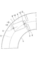
- FIGS. 6A and 6B are top views of the construction site showing the asphalt finisher 100 passing through the curved portion of the road RD to be constructed.
- FIG. 6A shows the movement of the asphalt finisher 100 when the steering device 53 automatically steers.
- FIG. 6B shows the movement of the asphalt finisher 100 when the manual steering is performed so that the predetermined point P at the central portion of the tractor 1 follows the center line CP of the road RD.
- the predetermined point P in the central portion of the tractor 1 is represented by “ ⁇ ”
- the predetermined point Q in the central portion of the front screed 30 is represented by “ ⁇ ”.
- the predetermined point Q at the central portion of the front screed 30 follows the trajectory PS indicated by the alternate long and short dash line. .. That is, when the asphalt finisher 100 passes through the curved portion of the road RD, the distance between the front end of the right side surface of the tractor 1 and the right boundary line RP of the road RD is the distance between the front end of the left side surface of the tractor 1 and the road RD. The distance between the front end of the right side surface of the front screed 30 and the right side boundary line RP of the road RD is the front end of the left side surface of the front screed 30.
- the driver of the asphalt finisher 100 assumes that when the asphalt finisher 100 passes through the curved portion of the road RD, the asphalt finisher 100 is moved so that the tractor 1 is located at the center in the width direction of the road RD.
- the screed 3 cannot be positioned at the center in the width direction of the road RD.
- the movement of the asphalt finisher 100 is automatically controlled by the steering device 53 so that the predetermined point P follows the target trajectory TPT, the movement of the asphalt finisher 100 is automatically controlled in the central portion of the front screed 30.
- the predetermined point Q follows the center line CP of the road RD indicated by the broken line. That is, when the asphalt finisher 100 passes through the curved portion of the road RD, the distance between the front end of the right side surface of the tractor 1 and the right boundary line RP of the road RD is the distance between the front end of the left side surface of the tractor 1 and the road RD.
- the distance between the front end of the right side surface of the front screed 30 and the right side boundary line RP of the road RD is smaller than the distance between the left side boundary line LP and the front end of the left side surface of the front side screed 30. It changes in a state almost equal to the distance between the road RD and the left boundary line LP of the road RD. Therefore, the pavement material is surely laid in the area inside the curved portion of the road RD, and the pavement material is not laid out of the right boundary line RP of the road RD. That is, the asphalt finisher 100 can match the width of the road RD to be constructed and the width of the new pavement NP even at the curved portion of the road RD.
- the controller 50 moves the screed 3 so that the tractor 1 approaches the end in the width direction of the road RD when the asphalt finisher 100 passes through the curved portion of the road RD. It can be located in the center of the road RD in the width direction.
- the asphalt finisher 100 has the tractor 1, the hopper 2 installed on the front side of the tractor 1 and accepting the pavement material, and the pavement material in the hopper 2 to the rear side of the tractor 1.
- the conveyor CV to be fed
- the pavement SC to spread the pavement material fed by the conveyor CV on the rear side of the tractor 1
- the screed 3 to spread the pavement material spread by the screw SC on the rear side of the screw SC.
- the movement of the tractor 1 is controlled based on the information acquisition device 51 that acquires information on the road to be constructed and the target track TPT or the target position Pf or Qf determined by the information on the road to be constructed acquired by the information acquisition device 51. It is provided with a controller 50 as a control device for the operation.
- the asphalt finisher 100 can appropriately lay a pavement along the road RD to be constructed.
- the controller 50 sets the target track TPT or the target position Pf on the road to be constructed at the curved portion of the road RD to be constructed. It may be configured to be set outside (right side) of the center of the RD (center line CP).
- the target orbit TPT is, for example, a target orbit to be followed by a predetermined point P in the central portion of the tractor 1, and the target position Pf is a point to be reached by the predetermined point P after a lapse of a predetermined time.
- the controller 50 may be configured to set the target track TPT or the target position Pf so that the center in the width direction of the road RD to be constructed coincides with the center in the width direction of the screed 3.
- the target calculation unit 50a of the controller 50 has a target trajectory TPT or a target position so that the trajectory drawn by the predetermined point Q in the central portion of the front screed 30 and the center line CP of the road RD coincide with each other. It may be configured to set Pf.
- the controller 50 can match the width of the road RD with the width of the new pavement NP even when the asphalt finisher 100 passes not only the straight portion of the road RD but also the curved portion.
- the controller 50 may be configured to set the target trajectory TPT or the target position Pf so that at least one end of the screed 3 coincides with the feature.
- the target trajectory TPT or the target position Pf may be set so as to match the RP.
- the target calculation unit 50a of the controller 50 may set the target trajectory TPT or the target position Pf so that the left end portion of the screed 3 and the left boundary line LP of the road RD coincide with each other.
- the target calculation unit 50a of the controller 50 may set the target trajectory TPT or the target position Pf so that the right end portion of the screed 3 and the right boundary line RP of the road RD coincide with each other.
- the controller 50 may be configured to set the target trajectory TPT or the target position Pf based on the distance in the front-rear direction between the predetermined point P as the steering reference point and the screed 3.
- the controller 50 may be configured to set the target trajectory TPT or the target position Pf based on the distance in the front-rear direction between the predetermined point P and the predetermined point Q at the center of the front screed 30.
- the controller 50 may be configured to set the target trajectory TPS or the target position Qf based on the distance in the front-rear direction between the predetermined point P as the steering reference point and the screed 3.
- the controller 50 may be configured to set the target trajectory TPS or the target position Qf based on the distance in the front-rear direction between the predetermined point P and the predetermined point Q in the central portion of the front screed 30.
- the target trajectory TPS is, for example, a target trajectory that the predetermined point Q in the central portion of the front screed 30 should follow, and the target position Qf is a point that the predetermined point Q should reach after the lapse of a predetermined time.
- the controller 50 controls the movement of the tractor 1 by controlling the steering angle of the front wheels 6, and in the case of a crawler-type asphalt finisher, the rotation speeds of the left crawler and the right crawler, respectively. May be configured to control the movement of the tractor 1 by individually controlling the tractor 1.
- the controller 50 paves along the road RD to be constructed by automatically controlling the movement of the asphalt finisher 100 regardless of whether the asphalt finisher 100 is a wheel type asphalt finisher or a crawler type asphalt finisher. You can lay your body properly.
- the controller 50 may be configured to control the movement of the tractor 1 so that the asphalt finisher 100 moves along a preset target trajectory TPT. Specifically, the controller 50 is configured to control the movement of the tractor 1 so that the asphalt finisher 100 moves along the target trajectory TPT set before the asphalt finisher 100 starts traveling. You may. However, the controller 50 may be configured to control the movement of the tractor 1 so that the asphalt finisher 100 moves along the target trajectory TPT calculated in real time.
- the controller 50 can easily and surely appropriately control the movement of the tractor 1.
- the information acquisition device 51 may be an image pickup device or a communication device 51T.
- the imaging device may be a LIDAR, a monocular camera, a stereo camera, a distance image camera, or the like.
- the steering device 53 is configured to expand and contract the front wheel steering cylinder installed near the front axle, but when a hydraulic steering motor is adopted instead of the front wheel steering cylinder. May be configured to rotate the hydraulic steering motor.
- the steering device 53 includes a steering electromagnetic control valve that controls the flow rate of hydraulic oil flowing from the hydraulic pump to the hydraulic steering motor.
- the steering electromagnetic control valve is configured to be able to control the inflow and outflow of hydraulic oil in the hydraulic steering motor according to the rotation of the steering wheel SH (steering wheel) as an operating device.
- the steering electromagnetic control valve is configured to be able to control the inflow and outflow of hydraulic oil in the hydraulic steering motor in response to a control command from the controller 50, regardless of the rotation of the steering wheel SH.
- the steering device 53 may be configured to control an electric motor that automatically rotates the steering wheel SH. In this case, the steering device can automatically control the movement of the asphalt finisher 100 by automatically rotating the steering wheel SH in response to a control command from the controller 50.
- Travel speed sensor 51T Communication device 52 ... In-vehicle display device 53 ... Steering device 100 ... Asphalt finisher AP ... Feature BS ... Roadbed CV ... Conveyor DS ... Automatic steering system NP ... New pavement Body PL ... Pole PV ... Pavement material SC ... Screw SH ... Steering wheel
Abstract
L'invention concerne un dispositif de finition d'asphalte (100) qui comprend : un tracteur (1) ; une trémie (2) installée sur le côté avant du tracteur (1), la trémie recevant un matériau de pavage ; un transporteur (CV) qui alimente le matériau de pavage à l'intérieur de la trémie (2) vers le côté arrière du tracteur (1) ; une vis (SC) qui étale le matériau de pavage alimenté par le transporteur (CV) sur le côté arrière du tracteur ; une poutre lisseuse (3) qui égalise le matériau de pavage étalé par la vis (SC) sur le côté arrière de la vis (SC) ; un dispositif d'acquisition d'informations (51) qui acquiert des informations relatives à une route à construire ; et un dispositif de commande (50) qui commande le mouvement du tracteur (1) sur la base d'une position cible (Pf) ou (Qf), ou d'une trajectoire cible (TPT) décidées selon les informations acquises par le dispositif d'acquisition d'informations (51) concernant la route à construire.
Priority Applications (3)
| Application Number | Priority Date | Filing Date | Title |
|---|---|---|---|
| JP2022510039A JPWO2021193351A1 (fr) | 2020-03-26 | 2021-03-18 | |
| CN202180007688.4A CN114901908A (zh) | 2020-03-26 | 2021-03-18 | 沥青滚平机 |
| EP21775663.4A EP4130383A4 (fr) | 2020-03-26 | 2021-03-18 | Dispositif de finition d'asphalte |
Applications Claiming Priority (2)
| Application Number | Priority Date | Filing Date | Title |
|---|---|---|---|
| JP2020056662 | 2020-03-26 | ||
| JP2020-056662 | 2020-03-26 |
Publications (1)
| Publication Number | Publication Date |
|---|---|
| WO2021193351A1 true WO2021193351A1 (fr) | 2021-09-30 |
Family
ID=77892556
Family Applications (1)
| Application Number | Title | Priority Date | Filing Date |
|---|---|---|---|
| PCT/JP2021/011078 WO2021193351A1 (fr) | 2020-03-26 | 2021-03-18 | Dispositif de finition d'asphalte |
Country Status (4)
| Country | Link |
|---|---|
| EP (1) | EP4130383A4 (fr) |
| JP (1) | JPWO2021193351A1 (fr) |
| CN (1) | CN114901908A (fr) |
| WO (1) | WO2021193351A1 (fr) |
Cited By (2)
| Publication number | Priority date | Publication date | Assignee | Title |
|---|---|---|---|---|
| JP7356690B1 (ja) | 2023-05-31 | 2023-10-05 | 株式会社レグラス | 作業車両の走行制御装置 |
| EP4286588A1 (fr) * | 2022-05-31 | 2023-12-06 | Sumitomo Heavy Industries, LTD. | Finisseur de route |
Citations (8)
| Publication number | Priority date | Publication date | Assignee | Title |
|---|---|---|---|---|
| JPS4912631A (fr) * | 1972-05-16 | 1974-02-04 | ||
| JPS6197713A (ja) * | 1984-10-17 | 1986-05-16 | Niigata Eng Co Ltd | 舗装作業車の自動操向装置 |
| JPH0547010U (ja) * | 1991-11-27 | 1993-06-22 | 新キャタピラー三菱株式会社 | アスファルトフィニッシャの自動ステアリング装置 |
| JPH0583806U (ja) * | 1992-04-03 | 1993-11-12 | 東洋運搬機株式会社 | 作業用車両 |
| JPH0731907U (ja) * | 1993-04-09 | 1995-06-16 | 建設省東北地方建設局長 | 舗装作業車の自動操向装置 |
| JP2017160636A (ja) | 2016-03-08 | 2017-09-14 | 住友建機株式会社 | アスファルトフィニッシャ |
| WO2019031318A1 (fr) * | 2017-08-08 | 2019-02-14 | 住友建機株式会社 | Engin de voirie |
| JP2020056662A (ja) | 2018-10-01 | 2020-04-09 | パイオニア株式会社 | 光軸調整用装置 |
Family Cites Families (3)
| Publication number | Priority date | Publication date | Assignee | Title |
|---|---|---|---|---|
| US5484227A (en) * | 1993-04-09 | 1996-01-16 | Niigata Engineering Co., Ltd. | Control device for asphalt finisher |
| CN104278616A (zh) * | 2014-09-28 | 2015-01-14 | 广东惠利普路桥信息工程有限公司 | 无人驾驶的摊铺机 |
| JP6896525B2 (ja) * | 2017-06-28 | 2021-06-30 | 住友建機株式会社 | アスファルトフィニッシャ |
-
2021
- 2021-03-18 EP EP21775663.4A patent/EP4130383A4/fr active Pending
- 2021-03-18 CN CN202180007688.4A patent/CN114901908A/zh active Pending
- 2021-03-18 WO PCT/JP2021/011078 patent/WO2021193351A1/fr unknown
- 2021-03-18 JP JP2022510039A patent/JPWO2021193351A1/ja active Pending
Patent Citations (8)
| Publication number | Priority date | Publication date | Assignee | Title |
|---|---|---|---|---|
| JPS4912631A (fr) * | 1972-05-16 | 1974-02-04 | ||
| JPS6197713A (ja) * | 1984-10-17 | 1986-05-16 | Niigata Eng Co Ltd | 舗装作業車の自動操向装置 |
| JPH0547010U (ja) * | 1991-11-27 | 1993-06-22 | 新キャタピラー三菱株式会社 | アスファルトフィニッシャの自動ステアリング装置 |
| JPH0583806U (ja) * | 1992-04-03 | 1993-11-12 | 東洋運搬機株式会社 | 作業用車両 |
| JPH0731907U (ja) * | 1993-04-09 | 1995-06-16 | 建設省東北地方建設局長 | 舗装作業車の自動操向装置 |
| JP2017160636A (ja) | 2016-03-08 | 2017-09-14 | 住友建機株式会社 | アスファルトフィニッシャ |
| WO2019031318A1 (fr) * | 2017-08-08 | 2019-02-14 | 住友建機株式会社 | Engin de voirie |
| JP2020056662A (ja) | 2018-10-01 | 2020-04-09 | パイオニア株式会社 | 光軸調整用装置 |
Non-Patent Citations (1)
| Title |
|---|
| See also references of EP4130383A4 |
Cited By (2)
| Publication number | Priority date | Publication date | Assignee | Title |
|---|---|---|---|---|
| EP4286588A1 (fr) * | 2022-05-31 | 2023-12-06 | Sumitomo Heavy Industries, LTD. | Finisseur de route |
| JP7356690B1 (ja) | 2023-05-31 | 2023-10-05 | 株式会社レグラス | 作業車両の走行制御装置 |
Also Published As
| Publication number | Publication date |
|---|---|
| EP4130383A4 (fr) | 2023-08-30 |
| CN114901908A (zh) | 2022-08-12 |
| JPWO2021193351A1 (fr) | 2021-09-30 |
| EP4130383A1 (fr) | 2023-02-08 |
Similar Documents
| Publication | Publication Date | Title |
|---|---|---|
| WO2020196539A1 (fr) | Finisseur d'asphalte | |
| US11054831B2 (en) | Automatic site planning for autonomous construction vehicles | |
| WO2021193351A1 (fr) | Dispositif de finition d'asphalte | |
| US6371566B1 (en) | Process and device for milling off traffic areas | |
| US11144055B2 (en) | Construction site planning for autonomous construction vehicles | |
| US10642265B2 (en) | System and method for controlling autonomous construction vehicles | |
| US11029704B2 (en) | Self-propelled construction machine and method for controlling a self-propelled construction machine | |
| JP2001262611A (ja) | 自走式建設機械を計画されたルートにおいて制御する方法 | |
| RU2757433C2 (ru) | Машина для устройства дорожного покрытия с интеллектуальной системой рулевого управления | |
| US11774965B2 (en) | Slipform paver and method for operating a slipform paver | |
| US20200048893A1 (en) | Control System for Movable Additive Manufacturing | |
| IT201800010464A1 (it) | Veicolo battipista con funzioni automatizzate e metodo per controllare un veicolo battipista | |
| JP7297762B2 (ja) | アスファルトフィニッシャ及びアスファルトフィニッシャの監視システム | |
| EP4286588A1 (fr) | Finisseur de route | |
| WO2020027205A1 (fr) | Finisseuse d'asphalte et dispositif de gestion pour engins de voirie | |
| JP2023154942A (ja) | 道路機械 | |
| US11640715B2 (en) | Birds eye view camera for an asphalt paver | |
| JP2023154944A (ja) | 道路機械の制御システム | |
| JP2023154946A (ja) | 道路機械 | |
| WO2022210622A1 (fr) | Dispositif de finition d'asphalte et système d'aide à la construction de dispositif de finition d'asphalte | |
| WO2022210978A1 (fr) | Finisseuse d'asphalte et système de pavage de surface de roulement | |
| EP4257747A1 (fr) | Système de commande de finisseuse de route | |
| WO2024071046A1 (fr) | Engin routier et système de pavage de surface de route | |
| EP4257746A1 (fr) | Finisseuse de route | |
| US20210002833A1 (en) | Self-propelled construction machine and method for controlling a self-propelled construction machine |
Legal Events
| Date | Code | Title | Description |
|---|---|---|---|
| 121 | Ep: the epo has been informed by wipo that ep was designated in this application |
Ref document number: 21775663 Country of ref document: EP Kind code of ref document: A1 |
|
| ENP | Entry into the national phase |
Ref document number: 2022510039 Country of ref document: JP Kind code of ref document: A |
|
| NENP | Non-entry into the national phase |
Ref country code: DE |
|
| ENP | Entry into the national phase |
Ref document number: 2021775663 Country of ref document: EP Effective date: 20221026 |