RU2757433C2 - Machine for paving device with smart steering system - Google Patents
Machine for paving device with smart steering system Download PDFInfo
- Publication number
- RU2757433C2 RU2757433C2 RU2019125865A RU2019125865A RU2757433C2 RU 2757433 C2 RU2757433 C2 RU 2757433C2 RU 2019125865 A RU2019125865 A RU 2019125865A RU 2019125865 A RU2019125865 A RU 2019125865A RU 2757433 C2 RU2757433 C2 RU 2757433C2
- Authority
- RU
- Russia
- Prior art keywords
- guide
- corner
- angle
- processing unit
- pivot point
- Prior art date
Links
Images


Classifications
-
- E—FIXED CONSTRUCTIONS
- E01—CONSTRUCTION OF ROADS, RAILWAYS, OR BRIDGES
- E01C—CONSTRUCTION OF, OR SURFACES FOR, ROADS, SPORTS GROUNDS, OR THE LIKE; MACHINES OR AUXILIARY TOOLS FOR CONSTRUCTION OR REPAIR
- E01C19/00—Machines, tools or auxiliary devices for preparing or distributing paving materials, for working the placed materials, or for forming, consolidating, or finishing the paving
- E01C19/48—Machines, tools or auxiliary devices for preparing or distributing paving materials, for working the placed materials, or for forming, consolidating, or finishing the paving for laying-down the materials and consolidating them, or finishing the surface, e.g. slip forms therefor, forming kerbs or gutters in a continuous operation in situ
- E01C19/4886—Machines, tools or auxiliary devices for preparing or distributing paving materials, for working the placed materials, or for forming, consolidating, or finishing the paving for laying-down the materials and consolidating them, or finishing the surface, e.g. slip forms therefor, forming kerbs or gutters in a continuous operation in situ for forming in a continuous operation kerbs, gutters, berms, safety kerbs, median barriers or like structures in situ, e.g. by slip-forming, by extrusion
-
- B—PERFORMING OPERATIONS; TRANSPORTING
- B62—LAND VEHICLES FOR TRAVELLING OTHERWISE THAN ON RAILS
- B62D—MOTOR VEHICLES; TRAILERS
- B62D11/00—Steering non-deflectable wheels; Steering endless tracks or the like
- B62D11/001—Steering non-deflectable wheels; Steering endless tracks or the like control systems
- B62D11/003—Electric or electronic control systems
-
- B—PERFORMING OPERATIONS; TRANSPORTING
- B62—LAND VEHICLES FOR TRAVELLING OTHERWISE THAN ON RAILS
- B62D—MOTOR VEHICLES; TRAILERS
- B62D11/00—Steering non-deflectable wheels; Steering endless tracks or the like
- B62D11/20—Endless-track steering having pivoted bogie carrying track
-
- B—PERFORMING OPERATIONS; TRANSPORTING
- B62—LAND VEHICLES FOR TRAVELLING OTHERWISE THAN ON RAILS
- B62D—MOTOR VEHICLES; TRAILERS
- B62D55/00—Endless track vehicles
- B62D55/06—Endless track vehicles with tracks without ground wheels
- B62D55/065—Multi-track vehicles, i.e. more than two tracks
-
- E—FIXED CONSTRUCTIONS
- E01—CONSTRUCTION OF ROADS, RAILWAYS, OR BRIDGES
- E01C—CONSTRUCTION OF, OR SURFACES FOR, ROADS, SPORTS GROUNDS, OR THE LIKE; MACHINES OR AUXILIARY TOOLS FOR CONSTRUCTION OR REPAIR
- E01C19/00—Machines, tools or auxiliary devices for preparing or distributing paving materials, for working the placed materials, or for forming, consolidating, or finishing the paving
- E01C19/004—Devices for guiding or controlling the machines along a predetermined path
-
- E—FIXED CONSTRUCTIONS
- E01—CONSTRUCTION OF ROADS, RAILWAYS, OR BRIDGES
- E01C—CONSTRUCTION OF, OR SURFACES FOR, ROADS, SPORTS GROUNDS, OR THE LIKE; MACHINES OR AUXILIARY TOOLS FOR CONSTRUCTION OR REPAIR
- E01C19/00—Machines, tools or auxiliary devices for preparing or distributing paving materials, for working the placed materials, or for forming, consolidating, or finishing the paving
- E01C19/48—Machines, tools or auxiliary devices for preparing or distributing paving materials, for working the placed materials, or for forming, consolidating, or finishing the paving for laying-down the materials and consolidating them, or finishing the surface, e.g. slip forms therefor, forming kerbs or gutters in a continuous operation in situ
- E01C19/4886—Machines, tools or auxiliary devices for preparing or distributing paving materials, for working the placed materials, or for forming, consolidating, or finishing the paving for laying-down the materials and consolidating them, or finishing the surface, e.g. slip forms therefor, forming kerbs or gutters in a continuous operation in situ for forming in a continuous operation kerbs, gutters, berms, safety kerbs, median barriers or like structures in situ, e.g. by slip-forming, by extrusion
- E01C19/4893—Apparatus designed for railless operation
Abstract
Description
ОБЛАСТЬ ТЕХНИКИFIELD OF TECHNOLOGY
Варианты выполнения идей изобретения, раскрытых здесь, в общем относятся к машине для устройства дорожного покрытия и текстурирующей машине, выполненной с возможностью программируемого управления.Embodiments of the inventive ideas disclosed herein generally relate to a paving machine and a programmable texturing machine.
УРОВЕНЬ ТЕХНИКИLEVEL OF TECHNOLOGY
Некоторые работы по устройству дорожного покрытия и текстурированию могут потребовать бетонирование в скользящей опалубке и/или текстурирование вокруг изогнутых поверхностей с чрезвычайно малым радиусом. Независимо от точной формы изогнутых поверхностей, которые могут включать в себя один или более радиусов, прямолинейные участки, спирали или изогнутые элементы свободной формы, машине для устройства дорожного покрытия для успешного бетонирования в скользящей опалубке или текстурирования бордюра (или сточного желоба) согласно этим изогнутым элементам необходима возможность направления машины вокруг кривых с малым радиусом или с переменным радиусом. Например, машина может быть направлена по изогнутому элементу против часовой стрелки (или налево), используя бордюрную опалубку или другой инструмент для изогнутой поверхности в требуемом положении. Согласно компоновке машины, во время руления против часовой стрелки левая передняя направляющая находится ближе к радиусу изогнутого элемента, чем задняя направляющая, так что, чтобы войти в кривую из прямолинейного положения, левая передняя направляющая должна повернуться на 70 градусов и задняя направляющая - на 20 градусов. Рулевой контроллер может попытаться повернуть наибольший угол направляющей на полной скорости, например, при 10 градусах/секунду; в этом случае, левой передней направляющей может потребоваться 7 секунд, чтобы достичь ее требуемого положения. Если две направляющие несинхронизованы, то обе направляющие достигнут положения с поворотом на 20 градусов через 2 секунды, и заданный элемент траектории не будет выдержан. Альтернативное решение, заключающееся в пропорциональном повороте направляющей, так что левая передняя направляющая находится под углом 35 градусов, когда задняя направляющая - под углом 10 градусов, также не выдерживает заданного элемента траектории.Some paving and texturing jobs may require slipforming concreting and / or texturing around extremely small radius curved surfaces. Regardless of the precise shape of curved surfaces, which may include one or more radii, straight sections, spirals or freeform curved elements, a paving machine for successful slipforming concreting or curb (or gutter) texturing according to these curved elements it is necessary to be able to guide the machine around curves with a small radius or with a variable radius. For example, the machine can be guided counterclockwise (or to the left) along the curved element using curb formwork or other tool to place the curved surface in the desired position. According to the machine layout, while taxiing counterclockwise, the left front guide is closer to the radius of the curved element than the rear guide, so to enter the curve from a straight position, the left front guide must rotate 70 degrees and the rear guide 20 degrees. ... The steering controller may try to turn the largest rail angle at full speed, for example at 10 degrees / second; in this case, it may take 7 seconds for the left front guide rail to reach its desired position. If the two guides are out of sync, then both guides will reach the 20 degree rotated position after 2 seconds and the specified path element will not be followed. An alternative solution to rotate the rail proportionally so that the left front rail is at 35 degrees when the rear rail is at 10 degrees is also out of alignment.
Следовательно, может быть желательным синхронизировать поворот направляющих относительно требуемого положения инструмента, более эффективно сводя к минимуму ошибку следования траектории - разницу между тем, где инструмент должен быть, и тем, где он фактически находится.Therefore, it may be desirable to synchronize the rotation of the rails with the desired tool position, more effectively minimizing path error — the difference between where the tool should be and where it actually is.
СУЩНОСТЬ ИЗОБРЕТЕНИЯSUMMARY OF THE INVENTION
Варианты выполнения идей изобретения, раскрытых здесь, направлены на интеллектуальную систему рулевого управления (интеллектуальный рулевой контроллер, ИРК) для машины для устройства дорожного покрытия или текстурирующей машины, выполненную с возможностью использования одного или более инструментов вдоль траектории, соответствующей изогнутой поверхности. ИРК может непрерывно принимать элементы траектории, либо вручную от оператора, либо от внешнего источника (например, для удаленной или автономной работы), соответствующие текущим и будущим положениям машины. Будущее положение может быть непосредственно впереди текущего положения или, если машина перемещается в обратном направлении, сзади текущего положения. Сравнивая текущий и будущий элементы, может быть выведено ожидаемое время выполнения для выхода из текущего положения и перехода к будущему положению (основанное, например, на скорости машины). Затем ИРК может выдерживать требуемый элемент траектории, сводя к минимуму ошибку следования траектории в течение ожидаемого времени выполнения посредством синхронизированного регулирования углов поворота поворачиваемых направляющих машины из положения, соответствующего текущему элементу траектории, в положение, соответствующее будущему элементу траектории. Таким образом, ИРК может выполнять функцию воображаемой поперечной тяги независимо от того, управляется ли машина автоматически или вручную и независимо от траектории поверхности (прямые линии, одиночный и составные радиусы, спирали, свободная форма), предотвращая повреждение, улучшая контроль сцепления и тягового усилия машины, и сохраняя срок службы ее компонентов.Embodiments of the teachings disclosed herein are directed to an intelligent steering system (intelligent steering controller, KFM) for a paving machine or texturizing machine, configured to use one or more tools along a path corresponding to a curved surface. The KFM can continuously receive trajectory elements, either manually from the operator or from an external source (for example, for remote or autonomous operation), corresponding to the current and future positions of the machine. The future position can be directly ahead of the current position or, if the machine is moving in the opposite direction, behind the current position. By comparing the current and future elements, the expected execution time for exiting the current position and moving to the future position (based, for example, on the speed of the machine), can be inferred. The KFM can then maintain the desired trajectory element, minimizing the trajectory following error during the expected execution time by synchronously adjusting the angles of rotation of the rotatable guides of the machine from a position corresponding to the current trajectory element to a position corresponding to a future trajectory element. Thus, the KFM can act as an imaginary lateral thrust regardless of whether the machine is automatically or manually controlled and regardless of the surface trajectory (straight lines, single and compound radii, spirals, freeform), preventing damage, improving traction control and traction of the machine. , and preserving the life of its components.
Ясно, что как вышеизложенное общее описание, так и следующее за ним подробное описание только служат в качестве примера, являются пояснительными и не ограничивают объем формулы изобретения. Сопровождающие чертежи, которые включены сюда и составляют часть описания, изображают примеры вариантов выполнения идей изобретения, раскрытых здесь, и вместе с общим описанием служат для пояснения принципов.It is clear that both the foregoing general description and the following detailed description only serve as examples, are explanatory and do not limit the scope of the claims. The accompanying drawings, which are incorporated herein and form part of the description, depict exemplary embodiments of the inventive ideas disclosed herein and, together with a general description, serve to explain the principles.
КРАТКОЕ ОПИСАНИЕ ЧЕРТЕЖЕЙBRIEF DESCRIPTION OF DRAWINGS
Множество преимуществ вариантов выполнения идей изобретения, раскрытых здесь, могут быть лучше поняты специалистами в данной области техники путем ссылки на сопровождающие фигуры, на которых:The many advantages of embodiments of the ideas of the invention disclosed herein may be better understood by those skilled in the art by reference to the accompanying figures, in which:
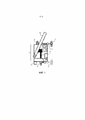
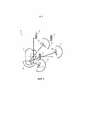
ФИГ.1 показывает вид сверху примера варианта выполнения машины для устройства дорожного покрытия или текстурирующей машины согласно идеям изобретения, раскрытым здесь;FIG. 1 shows a top view of an exemplary embodiment of a paving machine or texturing machine in accordance with the teachings of the invention disclosed herein;
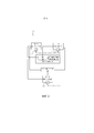
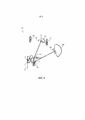
ФИГ.2 показывает схематичное изображение держателя инструмента, как на ФИГ.1;FIG. 2 shows a schematic representation of a tool holder as in FIG. 1;
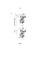
ФИГ.3 показывает изображение держателя инструмента с ФИГ.1 при работе;FIG. 3 shows an illustration of the tool holder of FIG. 1 in operation;
ФИГ.4A показывает изображение локально забазированной системы координат (СК) держателя инструмента с ФИГ.1;FIG. 4A shows an image of a locally gated coordinate system (CS) of the tool holder of FIG. 1;
ФИГ.4B показывает изображение работы держателя инструмента с ФИГ.1 с малым радиусом;FIG. 4B shows an illustration of the operation of the tool holder of FIG. 1 with a small radius;
ФИГ.4C показывает изображение работы держателя инструмента с ФИГ.1 с малым радиусом;FIG. 4C shows an illustration of the operation of the tool holder of FIG. 1 with a small radius; FIG.
ФИГ.4D показывает изображение работы держателя инструмента с ФИГ.1 с малым радиусом;FIG. 4D shows an illustration of the operation of the tool holder of FIG. 1 with a small radius; FIG.
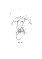
ФИГ.5 показывает изображение работы в обратном ходе держателя инструмента с ФИГ.1;FIG. 5 shows an illustration of a reverse stroke operation of the tool holder of FIG. 1;
ФИГ.6 показывает изображение работы по часовой стрелке держателя инструмента с ФИГ.1; иFIG. 6 shows an illustration of a clockwise operation of the tool holder of FIG. 1; and
ФИГ.7 показывает изображение комбинации работ держателя инструмента с ФИГ.1.FIG. 7 shows an illustration of a combination of operations of the tool holder of FIG. 1.
ПОДРОБНОЕ ОПИСАНИЕ ИЗОБРЕТЕНИЯDETAILED DESCRIPTION OF THE INVENTION
Перед подробным описанием по меньшей мере одного варианта выполнения идей изобретения, раскрытых здесь, ясно, что идеи изобретения не ограничены их применением к деталям конструкции и расположению компонентов или этапами или методами, излаженным далее в описании или изображенным на чертежах. Далее изложено подробное описание вариантов выполнения данных идей изобретения, множества конкретных деталей, для того чтобы обеспечить более полное понимание идей изобретения. Однако специалисту в данной области техники, извлекшему пользу из данного описания, будет понятно, что идеи изобретения, раскрытые здесь, могут быть использованы на практике без этих конкретных деталей. В других случаях, широко известные признаки могут быть не описаны подробно, чтобы исключить нежелательное усложнение данного описания. Идеи изобретения, раскрытые здесь, выполнены с возможностью воплощения в других вариантах выполнения или использования на практике или реализации другими способами. Также, ясно, что формулировки и терминология, использованные здесь, приводятся с целью описания и не являются ограничивающими.Before describing in detail at least one embodiment of the inventive ideas disclosed herein, it is clear that the inventive ideas are not limited to their application to details of construction and arrangement of components or to the steps or methods set forth in the description below or depicted in the drawings. The following is a detailed description of embodiments of these ideas of the invention, many specific details, in order to provide a more complete understanding of the ideas of the invention. However, a person skilled in the art who has benefitted from this description will understand that the inventive concepts disclosed herein may be practiced without these specific details. In other cases, well-known features may not be described in detail in order to avoid undesirable complication of this description. The inventive concepts disclosed herein are adapted to be embodied in other embodiments or used in practice or implemented in other ways. Also, it is clear that the language and terminology used herein are for descriptive purposes and are not limiting.
В данном контексте буква, следующая за ссылочной позицией, предназначена для обозначения варианта выполнения элемента или элемента, который может быть подобен, но необязательно идентичен, ранее описанному элементу или элементу, имеющему такую же ссылочную позицию (например, 1, 1a, 1b). Такие сокращенные обозначения используются только для удобства, и не ограничивают каким-либо образом идеи изобретения, раскрытые здесь, если иное явно не указано.In this context, the letter following the reference numeral is intended to denote an embodiment of an element or element that may be similar, but not necessarily identical, to a previously described element or element having the same reference numeral (e.g., 1, 1a, 1b). Such abbreviations are used for convenience only, and do not limit in any way the inventive concepts disclosed herein unless otherwise explicitly indicated.
Дополнительно, если иное явно не указано, ʺилиʺ относится к включающему или, а не к исключающему или. Например, условие A или B удовлетворяется при любом из следующего: A истинно (или присутствует) и B ложно (или отсутствует), A ложно (или отсутствует) и B истинно (или присутствует), и как A, так и B истинны (или присутствуют).Additionally, unless explicitly stated otherwise, "or" refers to an inclusive or rather than an exclusive or. For example, condition A or B is satisfied for any of the following: A is true (or present) and B is false (or absent), A is false (or absent) and B is true (or present), and both A and B are true (or are present).
Кроме того, в данном описании используется, в основном, единственное число для описания элементов и компонентов вариантов выполнения данных идей изобретения. Однако, это сделано только для удобства изложения общего смысла идей изобретения, и подразумевается, что эти элементы могут быть использованы и во множественном числе, если только не очевидно, что имелось ввиду иное.In addition, throughout this specification, the singular is generally used to describe the elements and components of embodiments of these teachings. However, this is done only for the convenience of presenting the general sense of the ideas of the invention, and it is intended that these elements may be used in the plural, unless it is obvious that otherwise is meant.
Наконец, в данном контексте любая ссылка на ʺодин вариант выполненияʺ или ʺнекоторые варианты выполненияʺ означает, что конкретный элемент, признак, конструкция или характеристика, описанная в связи с вариантом выполнения, включает в себя по меньшей мере один вариант выполнения идей изобретения, раскрытых здесь. Любое появление фразы ʺв некоторых вариантах выполненияʺ в различных местах в описании необязательно относится к одному варианту выполнения, и варианты выполнения раскрытых идей изобретения могут включать в себя один или более признаков, явно описанных или заведомо приведенных здесь, или любую комбинацию вспомогательных комбинаций двух или более таких признаков, вместе с любыми другими признаками, которые могут необязательно быть явно описаны или заведомо приведены в данном описании.Finally, in this context, any reference to "one embodiment" or "some embodiments" means that a particular element, feature, structure, or characteristic described in connection with an embodiment includes at least one embodiment of the teachings disclosed herein. Any occurrence of the phrase `` in some embodiments '' in various places in the description does not necessarily refer to a single embodiment, and embodiments of the disclosed inventive concepts may include one or more features explicitly described or known herein, or any combination of auxiliary combinations of two or more such features, along with any other features that may not necessarily be explicitly described or known in this description.
В общем, варианты выполнения идей изобретения, раскрытых здесь, направлены на систему интеллектуального рулевого управления (интеллектуальный рулевой контроллер, ИРК). ИРК в машине для устройства дорожного покрытия или текстурирующей машине принимает элементы траектории, соответствующие текущему и будущему положениям машины. Сравнивая текущий и будущий элементы, выводится ожидаемое время выполнения для выхода из текущего положения и перехода к будущему положению; Система интеллектуального рулевого управления синхронизирует регулировки поворачиваемых направляющих машины из текущей траектории в будущую траекторию. Интеллектуальная система рулевого управления выполняет функцию воображаемой поперечной тяги, предотвращая повреждение, улучшая контроль сцепления и тягового усилия машины, и сохраняя срок службы ее компонентов.In general, embodiments of the ideas of the invention disclosed herein are directed to an intelligent steering system (intelligent steering controller, KFM). The KFM in a paving machine or texturizing machine receives path elements corresponding to the current and future positions of the machine. By comparing the current and future items, the expected execution time is displayed to exit the current position and go to the future position; The Intelligent Steering system synchronizes the machine's pivot guide adjustments from the current track to the future track. The Intelligent Steering System acts as an imaginary lateral rod to prevent damage, improve traction and traction control of the machine, and preserve the life of its components.
Как показано ФИГ. 1, пример варианта выполнения держателя 100 инструмента (например, машина для устройства дорожного покрытия (или текстурирующая машина), содержащая один или более инструментов) согласно идеям изобретения, раскрытым здесь, может включать в себя шасси 102, встроенные в платформу 104 управления, с которой оператор может управлять перемещением машины 100 (держатель инструмента может приводиться в действие вручную или удаленно, или может работать автономно). Держатель 100 инструмента может включать в себя один или более инструментов 106, съемно установленных на машине, которые могут устанавливаться или сниматься с машины 100 в зависимости от требований к работе. Например, инструмент 106 может включать в себя, но не ограничен ими, бордюрную опалубку, барьерную опалубку, устройство для подравнивания, цилиндр, конвейер/шнек (108), распылитель, траншейный плуг, дробилку или подобный измельчитель, сеялку, отвал грейдера или комбинацию одного или более из выше описанных.As shown in FIG. 1, an exemplary embodiment of a tool holder 100 (e.g., a paving machine (or texturizing machine) containing one or more tools) in accordance with the teachings disclosed herein may include a
Держатель 100 инструмента может универсальным образом приводиться в движение и/или направляться любым из множества режимом (например, рулевое управление всеми колесами одновременно, рулевое управление только передними или только задними колесами, рулевое управление с поворотом передних и задних колес в противоположных направлениях, рулевое управление с контрвращением, рулевое управление инструментом) посредством ряда поворачиваемых гусеничных колес или направляющих 110. Каждая направляющая 110 может быть установлена на привод 112 для позиционирования направляющих 110 во множество конфигураций, включающая в себя рабочую конфигурацию, показанную на ФИГ. 1, и транспортную конфигурацию (не показана), в результате которой ширина машины может быть сведена к минимуму для эффективной транспортировки посредством грузовика-платформы или подобного транспортного средства. Каждая направляющая 110 может быть дополнительно установлена на привод 112 посредством углового привода или подобного поворотного привода 114, выполненного с возможностью поворота направляющей 110 на полные 360 градусов при вращении; таким образом, держатель 100 инструмента может направляться с оптимальной точностью посредством регулирования углов поворота каждой направляющей по отдельности. Каждая направляющая 110 может содержать поворотный рычаг 112a, выполненный с возможностью поворота посредством привода 112 (например, поворотный рычаг 112a и направляющая 110 могут быть повернуты как одно целое относительно общей оси Z, или направляющие 110 могут быть установлены на поворотные рычаги параллелограммного типа или телескопического/скользящего типа); поворотный рычаг 112a может быть дополнительно выполнен с возможностью обеспечения управления наклоном шасси 102 посредством подъема или опускания шасси 102 или направляющей 110 ʺвверхʺ или ʺвнизʺ (относительно оси Z) посредством линейных приводов.The tool holder 100 can be universally driven and / or guided by any of a variety of modes (e.g., all-wheel steering at the same time, front-wheel-only or rear-wheel-only steering, front and rear-wheel steering, counter-rotating steering, counter-rotation, tool steering) via a series of rotatable crawler wheels or
Поворот направляющих 110 во время остановки может вызвать смещение рамы. Смещение рамы вызывает дополнительные ошибки отслеживания траектории, приводящие к неправильному положению инструмента. Путем поворота направляющих 110 во время движения, замкнутая система управления непрерывно корректирует такие ошибки, так что ошибки отслеживания траектории вследствие смещения рамы снижаются до незначительных, допустимых уровней.Rotating the
Держатель 100 инструмента может включать в себя датчики 116 положения для измерения положения центра каждой направляющей 110, а также положения инструмента 106, и передачи этих положений в ИРК. Датчики 116 положения могут включать в себя интеллектуальные цилиндры для отклоняющихся стоек/поворотных рычагов телескопического или параллелограммного типа или датчики поворота для измерения угла поворота поворотного рычага 112 или направляющей 110. ИРК может использовать обратную связь от датчиков 116 положения, вместе с параметрами машины, характерными для держателя 100 инструмента (например, длина поворотного рычага, геометрия параллелограмме, убранные/выдвинутые положения телескопических элементов), чтобы динамически вычислять положения направляющей и инструмента для улучшенного рулевого управления и/или управления наклоном. ИРК может регулировать свои вычисления на основе изменений параметров машины, например, если вспомогательная направляющая 118 добавляется или удаляется (см. ФИГ.4A), если инструмент 106 добавляется, заменяется или изменяет положение, или если поворотный рычаг 112 поворачивается для изменения положения направляющей 110 (что может изменить распределение веса, центр тяжести и рулевые характеристики держателя 100 инструмента).The tool holder 100 may include
Как показано на ФИГ.2, держатель 100a инструмента может быть выполнен и может работать аналогично держателю 100 инструмента с ФИГ.1, за исключением того, что держатель 100a инструмента может содержать левую переднюю (ЛП) направляющую 110a, правую переднюю (ПП) направляющую 110b и установленную по центру заднюю (ЗЗ) направляющую 110c, каждая направляющая 110a-c соединена с бортовым источником 120 питания для приведения в действие направляющих и/или угловых/поворотных приводов 114. Каждая направляющая 110a-c может содержать угловой привод или поворотный привод 114 и датчики 116 поворота/положения. Датчики 116 положения могут передавать положение направляющей 110a-c в ИРК 122, а также угол поворота каждой отдельной направляющей 110a-c, например, относительно заданного отсчетного угла, например, номинального угла (130, ФИГ. 3), параллельного прямолинейному направлению (128, ФИГ. 3) для устройства дорожного покрытия. ИРК 122 может отслеживать положение и конфигурацию держателя 100a инструмента относительно предварительно запрограммированной плановой траектории, а также любую получаемую ошибку следования траектории (например, отклонение от прямой линии или воображаемой линии руления). На основе данных от ИРК 122 (а также, например, текущей геометрии и/или рулевых параметров машины), система 124 рулевого управления может изменять направление перемещения держателя 100a инструмента посредством поворота одной или более направляющих 110a-c.As shown in FIG. 2, the tool holder 100a may be configured and operate similarly to the tool holder 100 of FIG. 1, except that the tool holder 100a may include a left front (LF) guide 110a, a right front (RF) guide 110b and a center-mounted rear (RZ) rail 110c, each rail 110a-c is connected to an onboard power source 120 to drive the rails and / or angle /
Как показано на ФИГ. 3, держатель 100b инструмента может быть выполнен и может работать аналогично держателю 100a инструмента с ФИГ. 2. Для работы по прямой линии, например, для устройства дорожного покрытия или отделки прямого бордюра или сточного желоба 126, держатель 100b инструмента может перемещаться непосредственно вперед (например, параллельно направлению 128 для устройства дорожного покрытия) вручную, удаленно или автономно, причем каждая направляющая 110a-c установлена под номинальным углом 130 (например, практически нулевым углом, также параллельным направлению 128 для устройства дорожного покрытия, позволяя мини или микро коррекции в рулении посредством использования замкнутого рулевого контроллера, чтобы уменьшить ошибку следования траектории). Чтобы продолжить работу вдоль другого прямого направления 128a для устройства дорожного покрытия, например, под углом к начальному направлению 128 для устройства дорожного покрытия, держатель 100b инструмента может остановиться в заданной точке, синхронно повернуть каждую направляющую 110a-c на заданный угол 130a и переместиться вдоль нового направления 128a для устройства дорожного покрытия.As shown in FIG. 3, the tool holder 100b may be configured and operate similarly to the tool holder 100a of FIG. 2. For straight line operation, such as paving or finishing a straight curb or
В некоторых вариантах выполнения, переход от первого прямого направления 128 для устройства дорожного покрытия ко второму прямолинейному направлению 128a для устройства дорожного покрытия выполняется путем изменения передней точки руления для поворота всего держателя 100b инструмента и поддержания продольного края инструмента 106 касательным к траектории. В некоторых вариантах выполнения, переход от первого прямого направления 128 для устройства дорожного покрытия ко второму прямолинейному направлению 128a для устройства дорожного покрытия выполняется посредством изменения ориентации направляющих 110a-c без изменения ориентации держателя 100b инструмента. Такая ориентация может потребовать изменения ориентации инструмента 106.In some embodiments, the transition from the first
Однако некоторые операции держателя 100b инструмента для устройства дорожного покрытия или текстурирования могут содержать изогнутые поверхности, например, устройство бордюра по изогнутой поверхности 132, образованной малым радиусом 134; например, около 0,61 м (2 фута) или менее, по составной изогнутой поверхности, образованной более чем одним радиусом, или по спирали, содержащей постоянно изменяющиеся радиусы. Держатель 100b инструмента согласно вариантам выполнения настоящего описания может устранить ошибку отклонения от траектории более эффективно, чем обычные подходы посредством динамического сглаживания и управления заданными углами 130a направляющих и скоростями поворота направляющих, на основе изменений положения направляющей 110a-c от элемента траектории к элементу траектории, а также изменений положения инструмента и заданной оператором скорости инструмента.However, some operations of the paving or texturing tool holder 100b may include curved surfaces, such as curb along
В замкнутой системе ИРК можно выделить передний и задний компоненты ошибки, и умножить эти компоненты ошибки на диапазон руления, чтобы определить воображаемую коррекцию. Воображаемая коррекция может содержать угол на миллиметр ошибки. Воображаемая коррекция добавляется к мгновенным курсовым углам, чтобы обеспечить эффективные углы, связанные с передней и задней точками держателя 100b инструмента. При заданном положении передней и задней точек, и их эффективных углах, функция вычисляет точку пересечения двух линий, которая становится эффективной точкой синхронизации. Затем все углы направляющих и скорости хода обновляются, используя эффективную точка синхронизации для поворота направляющих 110a-c.In a closed KFM system, one can isolate the forward and backward error components, and multiply these error components by the steering range to determine an imaginary correction. The imaginary correction may contain an angle per millimeter of error. An imaginary correction is added to the instant heading angles to provide effective angles associated with the front and back points of the tool holder 100b. Given the position of the fore and aft points, and their effective angles, the function calculates the intersection point of the two lines, which becomes the effective synchronization point. All guide angles and travel speeds are then updated using the effective timing point to rotate the guide rails 110a-c.
Как показано в целом на ФИГ.4A-4E, держатель 100c инструмента может быть выполнен и может работать аналогично держателю 100b инструмента с ФИГ. 3, за исключением того, что ИРК (122, ФИГ. 2) держателя 100c инструмента может определять локальную систему координат, посредством которой любой компонент или точка держателя 100c инструмента может быть определена.As shown generally in FIGS. 4A-4E, the tool holder 100c may be configured and operate similarly to the tool holder 100b of FIG. 3, except that the KFM (122, FIG. 2) of the tool holder 100c can define a local coordinate system by which any component or point of the tool holder 100c can be determined.
Например, как показано, в частности, на ФИГ.4A, если держатель 100c инструмента должен устроить дорожное покрытие по изогнутой поверхности с малым радиусом (132, ФИГ.3) в направлении против часовой стрелки или влево, система координат может быть определена относительно положения 136 инструмента или, альтернативно, положения жесткой рамы машины (ЖРМ), или шасси 102, соответствующего заднему левому углу инструмента 106. Другие точки системы координат могут соответствовать набору координата [x, y] относительно начала координат [0, 0] в положении 136 инструмента. Наборы координат могут включать в себя координаты по оси Z (не показаны), например, если траектория содержит динамическое управление наклоном между трехмерными текущим и будущим элементами траектории или если относительная высота компонента важна для траектории по другим причинам. Предполагая, что направляющие 110a-c остаются в фиксированных положениях относительно инструмента 106 (и держателя 100c инструмента), направляющие могут быть определены соответственно координатами точек 136a-c (соответствующими локальным координатам [x1, y4], [x4, y3] и [x2, y0] и средней точкой шасси 102, образованной координатами точки 136d ([x3, y2]). ИРК может определять общую точку (142, ФИГ.4C) поворота на основе локальной системы координат. Для того, чтобы ИРК более эффективно сглаживал перемещение направляющих 110a-c по всей траектории, будущий элемент 138 траектории (прогнозная точка) может быть определена (например, в [x1, y0]) в качестве точки или вектора на оси y, где y больше 0 или меньше 0, так что, когда положение 136 инструмента соответствует текущему элементу (132, ФИГ.3) траектории изогнутой поверхности, будущий элемент 138 траектории может быть использован ИРК для динамического определения кривизны изогнутой поверхности 132 в будущем элементе траектории (и таким образом требуемые углы направляющих в будущем элементе траектории), а также времени выполнения для выхода из текущего элемента траектории и перехода к будущему элементу траектории. На основе этих определений, ИРК может синхронизировать поворот направляющих 110a-c из текущего положения, соответствующего текущему элементу траектории, в будущее положение, соответствующее будущему элементу 138 траектории, относительно общей точки поворота, в течение времени выполнения. Отметим, что, если держатель 100c инструмента изменил конфигурацию в режиме работы, например, если ЛП направляющая 110b была перемещена 110d относительно шасси 102 или другой направляющей 110a, 110c, локальная система координат может связать перемещенную направляющую 110d с новой точкой 136e направляющей, и ИРК может соответствующим образом изменить для нее рулевые и угловые вычисления.For example, as shown in particular in FIG. 4A, if the tool holder 100c is to pave the curved surface with a small radius (132, FIG. 3) in a counterclockwise or leftward direction, a coordinate system may be defined relative to position 136 tool or, alternatively, the position of the rigid machine frame (RMC), or
В некоторых вариантах выполнения, будущий элемент 138 траектории и текущая точка или текущий элемент траектории могут не находиться на оси y. Такие варианты выполнения могут быть применимы для построения или иным образом внедрения смещенных траекторий. Например, трехмерная конструкция и трехмерная система размещает бордюр в тупике; тогда, используя край бордюра, трехмерная система смещается наружу, чтобы разместить тротуар на постоянном расстоянии от бордюра/дороги. Затем трехмерная система может изменить обеспеченный конструктивный радиус, чтобы отразить смещение. Альтернативно, трехмерная система может изменить обеспеченное выравнивание, связанное с краем бордюра, на измененное значение x будущего элемента 138 траектории/текущего элемента траектории. Таким образом система создает смещенные формы без дополнительного проектирования в САПР новых файлов управления машиной.In some embodiments,
Как показано, в частности, на ФИГ.4B, держатель 100c инструмента может быть выполнен с возможностью устройства дорожного покрытия, согласно элементам траектории, полученным от оператора (или внешним образом), прямолинейной траектории (140) до перехода к изогнутой поверхности 132. Например, держатель 100c инструмента может начинать устраивать дорожное покрытие в точке, где положение 136 инструмента совмещено с концом прямойлинейной траектории 140 с правой стороны. Будущий элемент 138 траектории может быть выбран непосредственно перед положением 136 инструмента на прямолинейной траектории 140. Соответственно, каждая направляющая 110a-c может остаться под номинальным углом 130, выравненным по направлению 128 для устройства дорожного покрытия.As shown in particular in FIG. 4B, the tool holder 100c may be configured to pave, according to path elements received from an operator (or externally), a straight path (140) until transition to
Как показано, в частности, на ФИГ.4C, держатель 100c инструмента может перейти вперед, так что положение 136 инструмента может выйти за прямолинейную траекторию 140 и перейти к изогнутой траектории 132 с малым радиусом, образованной малым радиусом 134 и заданным центром (общей точкой) 142 поворота. ИРК (122, ФИГ.2) может отслеживать развитие положения 136 инструмента, соответствующего текущему элементу траектории, на основе, например, данных от датчиков 116 положения. Положение будущего элемента 138 траектории может означать, что инструмент 106 переходит к изогнутой траектории 132 с малым радиусом. По мере того, как инструмент 106 переходит к изогнутой траектории 132 с малым радиусом, будущие положение и ориентация 144a-c каждой направляющей, показанной в текущем положении/ориентации 110a-c, могут быть определены радиальным вектором 146a-c из каждой направляющей к общей точке 142 поворота. Например, каждый будущий элемент траектории, соответствующий будущему положению инструмента, может быть связан с положением/ориентацией 144a-c каждой направляющей 110a-c, перпендикулярной радиальному вектору 146a-c, включающему в себя, если задняя направляющая 110d не выравнена с инструментом 106, будущее положение/ориентацию 144d, перпендикулярную радиальному вектору 146d. Аналогично, на основе скорости машины, которая может оставаться или не оставаться постоянной, переход к каждому будущему элементу 138 траектории вдоль изогнутой траектории 132 с малым радиусом может быть связан с временем выполнения относительно текущего элемента траектории. Если, например, ФИГ.4B изображает начальное время t0, соответствующее положению 136 инструмента в текущем элементе траектории до перехода инструмента 106 к изогнутой траектории 132 с малым радиусом, тогда ФИГ.4C может изображать будущий элемент траектории, соответствующий последующему времени tx, в котором положение 136 инструмента переходит к изогнутой траектории 132 с малым радиусом. Тогда скорость, с которой ЛП и ЗП направляющие 110a-b поворачиваются до требуемых углов 148a-b направляющих, соответствующих их положению и ориентации 144a-b на будущем элементе траектории, соответствующем последующему времени tx, может быть определена на основе, например, поступательной скорости держателя 100c инструмента и определенного времени выполнения, заданного интервалом tx - t0 между текущим и будущим элементами траектории.As shown in particular in FIG. 4C, the tool holder 100c can move forward so that the
Как показано, в частности, на ФИГ.4D, в период времени tx соответствующий будущий элемент (138, ФИГ.4C) траектории может стать текущим элементом траектории, соответствующим текущему положению 136 инструмента на изогнутой траектории 132 с малым радиусом. Аналогично, на основе обновленных положений инструмента 106a и обновленных положений/ориентаций направляющих 144a-c ИРК может принять последующие будущие элементы траектории, соответствующие будущим положениям 136a-b инструмента, причем каждый будущий элемент 138a-b траектории соответствует положению/ориентации направляющих 110a-c, например, в будущие периоды времени ty и tz (например, 150a-c и 152a-c соответственно). ИРК может вычислить, на основе скорости машины и времени выполнения (например, ty - tx и tz - ty) между каждым будущим элементом траектории, когда будущий элемент траектории становится текущим элементом траектории, и последующим будущим элементом траектории, необходимый синхронизированный поворот каждой направляющей, чтобы поддержать изогнутую траекторию 132 с малым радиусом, когда направляющие достигают будущих элементов траектории в периоды времени ty (положения/ориентации 150a-c) и tz (положения/ориентации 152a-c) соответственно.As shown in particular in FIG. 4D, at time tx, the corresponding future path element (138, FIG. 4C) may become the current path element corresponding to the
Как показано в целом на ФИГ.5-7, держатель 100d инструмента может быть выполнен и может работать аналогично держателю 100c инструмента с ФИГ.4A-D, за исключением того что, ссылаясь в частности на ФИГ.5, ИРК держателя 100d инструмента может аналогично направлять держатель инструмента по изогнутым элементам траектории, в то же время перемещаясь в направлении 154 по часовой стрелке (например, ʺобратноʺ относительно ориентации держателя инструмента), и синхронизировать поворот направляющих 110a-c (156a-c) в положения/ориентации (158a-c), соответствующие будущему элементу 138a траектории (инструменту 106c).As shown generally in FIGS. 5-7, the tool holder 100d may be configured and operate similarly to the tool holder 100c of FIGS. 4A-D, except that, referring specifically to FIG. 5, the KFM of the tool holder 100d may similarly guide the tool holder along curved path elements while moving in
Как показано, в частности, на ФИГ.6, ИРК держателя 100d инструмента может синхронизировать поворот 160a-c направляющих 110a-c в положения/ориентации 162a-c, соответствующие будущему элементу 138 траектории, когда держатель 100d инструмента переходит по часовой стрелке и вперед вокруг изогнутого элемента 166 траектории.As shown in particular in FIG. 6, the KFM of the tool holder 100d can synchronize the rotation 160a-c of the guides 110a-c to positions / orientations 162a-c corresponding to the
Как показано, в частности, на ФИГ.7, держатель 100d инструмента может перемещаться вокруг изогнутого элемента 168 траектории, образованного множеством радиусов 134a-b и множеством общих точек 142a-b поворота. ИРК держателя инструмента может синхронизировать поворот направляющих 110a-c между текущим элементом траектории (положения/ориентации 148a-c) и будущим элементом траектории (положения/ориентации 170a-c) на основе первой общей точки 142a поворота (изогнутый элемент 168a траектории) или на основе второй общей точки 142b поворота (изогнутый элемент 168b траектории) в зависимости от положения будущего элемента траектории относительно изогнутой поверхности 168.As shown in particular in FIG. 7, the tool holder 100d is movable about a
Считается, что идеи изобретения, раскрытые здесь, и множество их сопутствующих преимуществ будут понятны из вышеизложенного описания вариантов выполнения раскрытых идей изобретения, и будет понятно, что различные изменения могут быть выполнены в части формы, конструкции и расположения ее компонентов без отступления от широкого объема идей изобретения, раскрытых здесь, или без потери всех их материальных преимуществ; и отдельные признаки из различных вариантов выполнения могут быть объединены, чтобы привести к другим вариантам выполнения. Описанная здесь ранее форма является только примером варианта выполнения, цель следующих пунктов формулы изобретения состоит в охвате и включении в себя таких изменений. Более того, любой из признаков, раскрытый в отношении любого из отдельных вариантов выполнения, может быть включен в любой другой вариант выполнения.It is believed that the inventive ideas disclosed herein, and many of their attendant advantages, will be apparent from the foregoing description of embodiments of the disclosed inventive ideas, and it will be understood that various changes may be made in terms of shape, construction, and arrangement of its components without departing from the broad scope of ideas. inventions disclosed here, or without loss of all their material advantages; and individual features from different embodiments may be combined to result in other embodiments. The previously described form is only an example of an embodiment, the purpose of the following claims is to cover and include such changes. Moreover, any of the features disclosed in relation to any of the individual embodiments may be included in any other embodiment.
Claims (107)
Applications Claiming Priority (5)
| Application Number | Priority Date | Filing Date | Title |
|---|---|---|---|
| US201762447153P | 2017-01-17 | 2017-01-17 | |
| US62/447,153 | 2017-01-17 | ||
| US15/873,206 | 2018-01-17 | ||
| PCT/US2018/014093 WO2018136549A1 (en) | 2017-01-17 | 2018-01-17 | Paving machine with smart steering control |
| US15/873,206 US10822029B2 (en) | 2017-01-17 | 2018-01-17 | Paving machine with smart steering control |
Publications (3)
| Publication Number | Publication Date |
|---|---|
| RU2019125865A RU2019125865A (en) | 2021-02-19 |
| RU2019125865A3 RU2019125865A3 (en) | 2021-05-06 |
| RU2757433C2 true RU2757433C2 (en) | 2021-10-15 |
Family
ID=62905563
Family Applications (1)
| Application Number | Title | Priority Date | Filing Date |
|---|---|---|---|
| RU2019125865A RU2757433C2 (en) | 2017-01-17 | 2018-01-17 | Machine for paving device with smart steering system |
Country Status (8)
| Country | Link |
|---|---|
| US (2) | US10822029B2 (en) |
| EP (1) | EP3571111B1 (en) |
| JP (1) | JP7444608B2 (en) |
| AU (2) | AU2018211060B2 (en) |
| CA (1) | CA3048525C (en) |
| MX (1) | MX2019008106A (en) |
| RU (1) | RU2757433C2 (en) |
| WO (1) | WO2018136549A1 (en) |
Families Citing this family (8)
| Publication number | Priority date | Publication date | Assignee | Title |
|---|---|---|---|---|
| US9908571B2 (en) * | 2010-03-26 | 2018-03-06 | Guntert & Zimmerman Const. Div., Inc. | Adjustable bolster swing legs for slipform paving machines |
| US11421389B2 (en) | 2018-12-28 | 2022-08-23 | Wirtgen Gmbh | Variable height mold |
| US11047095B2 (en) * | 2018-12-28 | 2021-06-29 | Wirtgen Gmbh | Variable height offset mold |
| US11518412B2 (en) | 2020-06-30 | 2022-12-06 | Zoox, Inc. | Trajectory determination for four-wheel steering |
| US11345400B2 (en) * | 2020-06-30 | 2022-05-31 | Zoox, Inc. | Trajectory tracking with four-wheel steering and steering limits |
| US11414127B2 (en) * | 2020-06-30 | 2022-08-16 | Zoox, Inc. | Trajectory tracking with four-wheel steering |
| US11254359B1 (en) * | 2021-06-02 | 2022-02-22 | Gomaco Corporation | Leg assembly for construction machine |
| WO2023018762A1 (en) * | 2021-08-11 | 2023-02-16 | Gomaco Corporation | Slipform paver control |
Citations (5)
| Publication number | Priority date | Publication date | Assignee | Title |
|---|---|---|---|---|
| RU2316443C2 (en) * | 2005-11-21 | 2008-02-10 | РЯЗАНСКИЙ ВОЕННЫЙ АВТОМОБИЛЬНЫЙ ИНСТИТУТ им. генерала армии В.П. Дубынина | Method of steering wheel-and-track vehicle |
| US20090060658A1 (en) * | 2003-09-17 | 2009-03-05 | Cedarapids, Inc. | Frame raising multi-use paving tractor with blind mateable quick connecting tool attachments |
| DE102012001289A1 (en) * | 2012-01-25 | 2013-07-25 | Wirtgen Gmbh | Self-propelled construction machine and method for controlling a self-propelled construction machine |
| US20160137242A1 (en) * | 2014-11-13 | 2016-05-19 | Wirtgen Gmbh | Transport Mode Conversion |
| US20160347364A1 (en) * | 2015-05-29 | 2016-12-01 | Mtd Products Inc | Utility vehicle |
Family Cites Families (11)
| Publication number | Priority date | Publication date | Assignee | Title |
|---|---|---|---|---|
| JP3361280B2 (en) * | 1998-11-16 | 2003-01-07 | 日本輸送機株式会社 | Three-wheel steering automatic guided vehicle |
| JP2001225744A (en) * | 2000-02-18 | 2001-08-21 | Mitsubishi Heavy Ind Ltd | Steering control device for unmanned carrying vehicle |
| AUPR047300A0 (en) * | 2000-10-03 | 2000-10-26 | Spark, Ian James | Improved off road vehicle |
| US6581525B2 (en) * | 2001-05-09 | 2003-06-24 | Columbia Trailer Co., Inc. | Method and apparatus for transporting and steering a load |
| KR20080036200A (en) * | 2005-07-22 | 2008-04-25 | 인피니트랙, 엘엘씨 | Steering systems, steering and speed coordination systems, and associated vehicles |
| WO2007079346A2 (en) * | 2005-12-30 | 2007-07-12 | Olsen Christopher J | Articulated wheel assemblies and vehicles therewith |
| SE530289C2 (en) * | 2006-10-13 | 2008-04-22 | Seco Tools Ab | Negative lathe with a phase between cutting edge and release side |
| WO2008124657A1 (en) * | 2007-04-05 | 2008-10-16 | Power Curbers, Inc. | Methods and systems utilizing 3d control to define a path of operation for a construction machine |
| JP4433060B2 (en) * | 2008-02-18 | 2010-03-17 | トヨタ自動車株式会社 | Parking assistance device |
| EP2974942B1 (en) * | 2014-06-30 | 2017-07-12 | Danfoss Power Solutions Aps | A method for controlling steering of a vehicle |
| JP7178363B2 (en) * | 2017-05-02 | 2022-11-25 | ゴマコ・コーポレーション | Free steering system for mobile machinery |
-
2018
- 2018-01-17 RU RU2019125865A patent/RU2757433C2/en active
- 2018-01-17 JP JP2019535290A patent/JP7444608B2/en active Active
- 2018-01-17 CA CA3048525A patent/CA3048525C/en active Active
- 2018-01-17 WO PCT/US2018/014093 patent/WO2018136549A1/en unknown
- 2018-01-17 US US15/873,206 patent/US10822029B2/en active Active
- 2018-01-17 EP EP18742208.4A patent/EP3571111B1/en active Active
- 2018-01-17 MX MX2019008106A patent/MX2019008106A/en unknown
- 2018-01-17 AU AU2018211060A patent/AU2018211060B2/en active Active
-
2019
- 2019-07-08 AU AU2019100743A patent/AU2019100743A4/en active Active
-
2020
- 2020-11-02 US US17/087,465 patent/US11713073B2/en active Active
Patent Citations (5)
| Publication number | Priority date | Publication date | Assignee | Title |
|---|---|---|---|---|
| US20090060658A1 (en) * | 2003-09-17 | 2009-03-05 | Cedarapids, Inc. | Frame raising multi-use paving tractor with blind mateable quick connecting tool attachments |
| RU2316443C2 (en) * | 2005-11-21 | 2008-02-10 | РЯЗАНСКИЙ ВОЕННЫЙ АВТОМОБИЛЬНЫЙ ИНСТИТУТ им. генерала армии В.П. Дубынина | Method of steering wheel-and-track vehicle |
| DE102012001289A1 (en) * | 2012-01-25 | 2013-07-25 | Wirtgen Gmbh | Self-propelled construction machine and method for controlling a self-propelled construction machine |
| US20160137242A1 (en) * | 2014-11-13 | 2016-05-19 | Wirtgen Gmbh | Transport Mode Conversion |
| US20160347364A1 (en) * | 2015-05-29 | 2016-12-01 | Mtd Products Inc | Utility vehicle |
Also Published As
| Publication number | Publication date |
|---|---|
| US10822029B2 (en) | 2020-11-03 |
| JP7444608B2 (en) | 2024-03-06 |
| CA3048525A1 (en) | 2018-07-26 |
| US20180208240A1 (en) | 2018-07-26 |
| CA3048525C (en) | 2023-11-14 |
| US11713073B2 (en) | 2023-08-01 |
| RU2019125865A (en) | 2021-02-19 |
| WO2018136549A1 (en) | 2018-07-26 |
| AU2018211060B2 (en) | 2020-10-22 |
| MX2019008106A (en) | 2020-02-07 |
| AU2018211060A1 (en) | 2019-07-11 |
| US20210114655A1 (en) | 2021-04-22 |
| EP3571111B1 (en) | 2022-07-27 |
| EP3571111A1 (en) | 2019-11-27 |
| JP2020514161A (en) | 2020-05-21 |
| EP3571111A4 (en) | 2020-10-28 |
| AU2019100743A4 (en) | 2019-08-08 |
| RU2019125865A3 (en) | 2021-05-06 |
Similar Documents
| Publication | Publication Date | Title |
|---|---|---|
| RU2757433C2 (en) | Machine for paving device with smart steering system | |
| CN101713999B (en) | Navigation control method of underground autonomous scraper | |
| CN211312127U (en) | Self-propelled construction machine | |
| US11029704B2 (en) | Self-propelled construction machine and method for controlling a self-propelled construction machine | |
| US11566387B2 (en) | Relative velocity based actuator velocity calibration system | |
| JP7178363B2 (en) | Free steering system for mobile machinery | |
| US10704209B2 (en) | Slipform paver and method for operating a slipform paver | |
| WO2021193351A1 (en) | Asphalt finisher | |
| CN111456748B (en) | Deviation correction control method for automatic guiding of hard rock tunneling machine | |
| US20230322300A1 (en) | Paving machine with smart steering control | |
| US11578737B2 (en) | Distance based actuator velocity calibration system | |
| EP4286588A1 (en) | Asphalt road finisher | |
| EP3619588B1 (en) | Freesteering system for mobile machines | |
| CN112252130B (en) | Self-propelled construction machine and method for controlling a self-propelled construction machine | |
| JP2024038900A (en) | asphalt finisher | |
| CN116892150A (en) | Control system of road machinery |