以下、本開示の実施の形態について、図面を参照しながら詳細に説明する。以下では、複数の実施の形態について説明するが、各実施の形態で説明された構成を適宜組合わせることは出願当初から予定されている。なお、図中同一又は相当部分には同一符号を付してその説明は繰り返さない。
Hereinafter, embodiments of the present disclosure will be described in detail with reference to the drawings. Hereinafter, a plurality of embodiments will be described, but it is planned from the beginning of the application that the configurations described in the respective embodiments are appropriately combined. The same or corresponding parts in the drawings are designated by the same reference numerals, and the description thereof will not be repeated.
(冷凍サイクル装置の構成)
図1は、実施の形態による冷凍サイクル装置の全体構成図である。なお、図1では、冷凍サイクル装置における各機器の接続関係および配置構成を機能的に示しており、物理的な空間における配置を必ずしも示すものではない。
(Configuration of refrigeration cycle equipment)
FIG. 1 is an overall configuration diagram of a refrigeration cycle device according to an embodiment. Note that FIG. 1 functionally shows the connection relationship and the arrangement configuration of each device in the refrigeration cycle apparatus, and does not necessarily show the arrangement in the physical space.
図1を参照して、冷凍サイクル装置1は、室外ユニット2と、負荷装置3と、延長配管84,88とを備える。
With reference to FIG. 1, the refrigeration cycle device 1 includes an outdoor unit 2, a load device 3, and extension pipes 84 and 88.
室外ユニット2は、負荷装置3に接続されるように構成された冷凍サイクル装置1の室外ユニットである。室外ユニット2は、吸入ポートG1、吐出ポートG2、中間圧ポートG3を有する圧縮機10と、凝縮器20と、ファン22と、熱交換器(エコノマイザ)30と、第2膨張弁40と、配管80~83、89とを備える。熱交換器30は、第1通路H1および第2通路H2を有し、第1通路H1を流れる冷媒と第2通路H2を流れる冷媒との間で熱交換を行なうように構成される。
The outdoor unit 2 is an outdoor unit of the refrigeration cycle device 1 configured to be connected to the load device 3. The outdoor unit 2 includes a compressor 10 having a suction port G1, a discharge port G2, and an intermediate pressure port G3, a condenser 20, a fan 22, a heat exchanger (economizer) 30, a second expansion valve 40, and piping. It includes 80 to 83 and 89. The heat exchanger 30 has a first passage H1 and a second passage H2, and is configured to exchange heat between the refrigerant flowing through the first passage H1 and the refrigerant flowing through the second passage H2.
負荷装置3は、第1膨張弁50と、蒸発器60と、配管85、86,87とを含む。蒸発器60は空気と冷媒との間で熱交換を行なう。冷凍サイクル装置1では、蒸発器60は、冷媒を冷却対象空間の空気からの吸熱によって蒸発させる。第1膨張弁50は冷媒を減圧することができる電子膨張弁である。なお、第1膨張弁50は、たとえば、室外ユニット2と独立して制御される温度膨張弁であってもよい。
The load device 3 includes a first expansion valve 50, an evaporator 60, and pipes 85, 86, 87. The evaporator 60 exchanges heat between air and the refrigerant. In the refrigeration cycle device 1, the evaporator 60 evaporates the refrigerant by endothermic heat from the air in the cooling target space. The first expansion valve 50 is an electronic expansion valve capable of reducing the pressure of the refrigerant. The first expansion valve 50 may be, for example, a temperature expansion valve that is controlled independently of the outdoor unit 2.
圧縮機10は、配管89および配管96から吸入される冷媒を圧縮して配管80へ吐出する。圧縮機10は、インバータ制御により駆動周波数を任意に変更することができる。また、圧縮機10には中間圧ポートG3が設けられており中間圧ポートG3からの冷媒を圧縮工程の途中部分に流入させることができる。圧縮機10は、制御装置100(図2参照)からの制御信号に従って回転速度を調整するように構成される。圧縮機10の回転速度を調整することで冷媒の循環量が調整され、冷凍サイクル装置1の能力を調整することができる。圧縮機10には種々のタイプのものを採用可能であり、たとえば、スクロールタイプ、ロータリータイプ、スクリュータイプ等のものを採用し得る。
The compressor 10 compresses the refrigerant sucked from the pipe 89 and the pipe 96 and discharges it to the pipe 80. The drive frequency of the compressor 10 can be arbitrarily changed by inverter control. Further, the compressor 10 is provided with an intermediate pressure port G3, so that the refrigerant from the intermediate pressure port G3 can flow into a portion in the middle of the compression process. The compressor 10 is configured to adjust the rotation speed according to a control signal from the control device 100 (see FIG. 2). By adjusting the rotation speed of the compressor 10, the circulation amount of the refrigerant is adjusted, and the capacity of the refrigeration cycle device 1 can be adjusted. Various types of compressors 10 can be adopted, and for example, scroll type, rotary type, screw type and the like can be adopted.
凝縮器20は、圧縮機10から吐出された高温高圧のガス冷媒が外気と熱交換(放熱)を行なうように構成される。この熱交換により、冷媒は凝縮されて液相に変化する。圧縮機10から配管80に吐出された冷媒は、凝縮器20において凝縮液化され配管81へ流出する。熱交換の効率を上げるため外気を送るファン22が凝縮器20に取り付けられている。ファン22は、凝縮器20において冷媒が熱交換を行なう外気を凝縮器20に供給する。ファン22の回転速度を調整することにより、圧縮機10の吐出側の冷媒圧力(高圧側圧力)を調整することができる。第2膨張弁40は凝縮器20から出てきた冷媒を減圧することができる電子膨張弁である。
The condenser 20 is configured such that a high-temperature and high-pressure gas refrigerant discharged from the compressor 10 exchanges heat (heat dissipation) with the outside air. By this heat exchange, the refrigerant is condensed and changed to a liquid phase. The refrigerant discharged from the compressor 10 to the pipe 80 is condensed and liquefied in the condenser 20 and flows out to the pipe 81. A fan 22 for sending outside air is attached to the condenser 20 in order to improve the efficiency of heat exchange. The fan 22 supplies the condenser 20 with outside air through which the refrigerant exchanges heat in the condenser 20. By adjusting the rotation speed of the fan 22, the refrigerant pressure (high pressure side pressure) on the discharge side of the compressor 10 can be adjusted. The second expansion valve 40 is an electronic expansion valve capable of reducing the pressure of the refrigerant discharged from the condenser 20.
圧縮機10から、凝縮器20、熱交換器30の第1通路H1、第2膨張弁40に至る流路は、負荷装置3の第1膨張弁50および蒸発器60が配置される流路と共に、冷媒が循環する循環流路を形成する。以下、この循環流路を冷凍サイクルの「主冷媒回路」とも言う。
The flow path from the compressor 10 to the condenser 20, the first passage H1 of the heat exchanger 30, and the second expansion valve 40 is together with the flow path in which the first expansion valve 50 and the evaporator 60 of the load device 3 are arranged. , Form a circulation flow path through which the refrigerant circulates. Hereinafter, this circulation flow path is also referred to as a "main refrigerant circuit" of the refrigeration cycle.
室外ユニット2は、主冷媒回路から分岐して第2通路H2を経由して圧縮機10に冷媒を送る「インジェクション流路101」をさらに備える。インジェクション流路101は、主冷媒回路の高圧部である配管81から第2通路H2の入口に冷媒を流すための「第1冷媒流路」(配管91~94)と、第2通路H2の出口から圧縮機10の中間圧ポートG3に冷媒を流す「第2冷媒流路」(配管96)とを含む。
The outdoor unit 2 further includes an "injection flow path 101" that branches from the main refrigerant circuit and sends the refrigerant to the compressor 10 via the second passage H2. The injection flow path 101 includes a "first refrigerant flow path" (pipes 91 to 94) for flowing a refrigerant from the pipe 81, which is a high-pressure portion of the main refrigerant circuit, to the inlet of the second passage H2, and an outlet of the second passage H2. Includes a "second refrigerant flow path" (pipe 96) that allows the refrigerant to flow through the intermediate pressure port G3 of the compressor 10.
インジェクション流路101の第2冷媒流路(配管96)には、開閉弁75が配置される。開閉弁75により冷媒を圧縮機10の中間圧ポートG3に供給するのか否かを調整することができる。なお、図1には示していないが、第2冷媒流路(配管96)に配置され、第2通路H2の出口から流出する冷媒の行き先として吸入ポートG1および中間圧ポートG3のいずれか一方を選択可能な流路切替装置をさらに備えるようにしてもよい。
An on-off valve 75 is arranged in the second refrigerant flow path (pipe 96) of the injection flow path 101. It is possible to adjust whether or not the refrigerant is supplied to the intermediate pressure port G3 of the compressor 10 by the on-off valve 75. Although not shown in FIG. 1, one of the suction port G1 and the intermediate pressure port G3 is used as the destination of the refrigerant that is arranged in the second refrigerant flow path (pipe 96) and flows out from the outlet of the second passage H2. A selectable flow path switching device may be further provided.
インジェクション流路101の第1冷媒流路には、冷媒を貯留する受液器(レシーバ)73と、第3膨張弁71とが配置される。受液器73の入口は、配管91,92によって、配管81(すなわち循環流路における、凝縮器20の出口と第1通路H1の入口との間の部分)に接続される。第3膨張弁71は、配管91,92の途中部分に配置される。
A receiver (receiver) 73 for storing the refrigerant and a third expansion valve 71 are arranged in the first refrigerant flow path of the injection flow path 101. The inlet of the liquid receiver 73 is connected to the pipe 81 (that is, the portion of the circulation flow path between the outlet of the condenser 20 and the inlet of the first passage H1) by the pipes 91 and 92. The third expansion valve 71 is arranged in the middle of the pipes 91 and 92.
インジェクション流路101の第1冷媒流路には、さらに、流量調整弁72と、ガス抜き通路95とが配置される。流量調整弁72は、受液器73の出口の配管93と、第2通路H2に通じる配管94との間に配置される膨張弁である。ガス抜き通路95は、受液器73のガス排出口と第2通路H2とを接続し、受液器73内の冷媒ガスを排出する。
A flow rate adjusting valve 72 and a gas vent passage 95 are further arranged in the first refrigerant flow path of the injection flow path 101. The flow rate adjusting valve 72 is an expansion valve arranged between the pipe 93 at the outlet of the liquid receiver 73 and the pipe 94 leading to the second passage H2. The gas vent passage 95 connects the gas discharge port of the liquid receiver 73 and the second passage H2, and discharges the refrigerant gas in the liquid receiver 73.
配管91は、主冷媒回路の高圧部である配管81から分岐し、受液器73へ冷媒を流入させる配管である。第3膨張弁71は、主冷媒回路の高圧部である配管81の冷媒を中間圧力まで低下させることができる電子膨張弁である。受液器73は、減圧され二相となった冷媒を容器内で気液の分離を行ない、冷媒を貯蔵し主冷媒回路の冷媒量を調整することができる容器である。受液器73の上部に接続されるガス抜き通路95と受液器73の下部に接続される配管93は、受液器73の中でガス冷媒と液冷媒に分離した冷媒を分離した状態で取り出すための配管である。流量調整弁72は、配管93から排出される液冷媒の循環量を調整することで受液器73の冷媒量を調整することができる。
The pipe 91 is a pipe that branches from the pipe 81, which is a high-pressure portion of the main refrigerant circuit, and allows the refrigerant to flow into the liquid receiver 73. The third expansion valve 71 is an electronic expansion valve capable of reducing the refrigerant in the pipe 81, which is a high-pressure portion of the main refrigerant circuit, to an intermediate pressure. The liquid receiver 73 is a container capable of separating the gas and liquid in the container from the decompressed and two-phase refrigerant, storing the refrigerant, and adjusting the amount of the refrigerant in the main refrigerant circuit. The gas vent passage 95 connected to the upper part of the receiver 73 and the pipe 93 connected to the lower part of the receiver 73 are in a state where the refrigerant separated into the gas refrigerant and the liquid refrigerant is separated in the receiver 73. It is a pipe for taking out. The flow rate adjusting valve 72 can adjust the amount of refrigerant in the liquid receiver 73 by adjusting the amount of circulation of the liquid refrigerant discharged from the pipe 93.
このようにインジェクション流路101に受液器73を設けることにより、主冷媒回路の液管である配管82,83における過冷却度を確保することが容易となる。受液器73には一般にガス冷媒が含まれるため受液器73内の冷媒温度は飽和温度となるところ、仮に受液器73を主冷媒回路の液管である配管82に配置すると、配管82内の冷媒温度が飽和温度よりも低下し難くなり過冷却度を確保できないからである。
By providing the liquid receiver 73 in the injection flow path 101 in this way, it becomes easy to secure the degree of supercooling in the pipes 82 and 83 which are the liquid pipes of the main refrigerant circuit. Since the receiver 73 generally contains a gas refrigerant, the refrigerant temperature in the receiver 73 becomes a saturation temperature. However, if the receiver 73 is arranged in the pipe 82 which is the liquid pipe of the main refrigerant circuit, the pipe 82 This is because the temperature of the refrigerant inside is less likely to drop below the saturation temperature, and the degree of supercooling cannot be ensured.
熱交換器30は、主冷媒回路の一部である第1通路H1を流れる冷媒と、インジェクション流路101の一部である第2通路H2を流れる冷媒との間の熱交換を行なう。
The heat exchanger 30 exchanges heat between the refrigerant flowing through the first passage H1 which is a part of the main refrigerant circuit and the refrigerant flowing through the second passage H2 which is a part of the injection flow path 101.
仮に主冷媒回路の高圧部である配管81,91に受液器73を設けると、配管81,91の圧力が高く配管81,91内の冷媒が超臨界状態である場合には、受液器73へ液冷媒を貯蔵することができず、受液器73による余剰冷媒量のバッファ機能が失われてしまう。これに対し、本実施の形態においては、第3膨張弁71によって中間圧力まで低下された中間圧部分である配管92に受液器73を設けることで、超臨界状態での運転においても冷媒量の調整が可能となる。
If the liquid receiver 73 is provided in the pipes 81 and 91, which are the high-pressure parts of the main refrigerant circuit, if the pressure in the pipes 81 and 91 is high and the refrigerant in the pipes 81 and 91 is in a supercritical state, the liquid receiver The liquid refrigerant cannot be stored in the 73, and the function of buffering the excess refrigerant amount by the receiver 73 is lost. On the other hand, in the present embodiment, by providing the liquid receiver 73 in the pipe 92 which is the intermediate pressure portion lowered to the intermediate pressure by the third expansion valve 71, the amount of refrigerant even in the operation in the supercritical state Can be adjusted.
図2は、図1に示した冷凍サイクル装置1に配置される各種センサと制御装置100とを示した図である。図2を参照して、室外ユニット2は、さらに、圧力センサ110~113と、温度センサ120~125と、報知装置150と、制御装置100とを備える。
FIG. 2 is a diagram showing various sensors and a control device 100 arranged in the refrigeration cycle device 1 shown in FIG. With reference to FIG. 2, the outdoor unit 2 further includes pressure sensors 110 to 113, temperature sensors 120 to 125, a notification device 150, and a control device 100.
圧力センサ110は、圧縮機10の吸入ポート部分の圧力PLを検出し、その検出値を制御装置100へ出力する。圧力センサ111は、圧縮機10の吐出圧PHを検出し、その検出値を制御装置100へ出力する。圧力センサ112は、第2膨張弁40の出口の配管83の圧力P1を検出し、その検出値を制御装置100へ出力する。また、圧力センサ113は第3膨張弁71の後の配管92の中間圧力PMを検出し、その検出値を制御装置100へ出力する。
The pressure sensor 110 detects the pressure PL of the suction port portion of the compressor 10 and outputs the detected value to the control device 100. The pressure sensor 111 detects the discharge pressure PH of the compressor 10 and outputs the detected value to the control device 100. The pressure sensor 112 detects the pressure P1 of the pipe 83 at the outlet of the second expansion valve 40, and outputs the detected value to the control device 100. Further, the pressure sensor 113 detects the intermediate pressure PM of the pipe 92 after the third expansion valve 71, and outputs the detected value to the control device 100.
室外ユニット2は、第2膨張弁40を液管に備えることによって、負荷装置3の設計圧(たとえば、4MPa)以下に冷媒圧力を減圧してから負荷装置3に送出することができる。これによりCO2などの超臨界を利用する冷媒を使用しても、負荷装置3として従来と同じ設計圧の汎用製品を使用することができる。
By providing the liquid pipe with the second expansion valve 40, the outdoor unit 2 can reduce the refrigerant pressure to or less than the design pressure (for example, 4 MPa) of the load device 3 and then deliver the refrigerant pressure to the load device 3. As a result, even if a refrigerant that utilizes supercritical fluid such as CO 2 is used, a general-purpose product having the same design pressure as the conventional one can be used as the load device 3.
温度センサ120は、圧縮機10の吐出温度THを検出し、その検出値を制御装置100へ出力する。温度センサ121は、凝縮器20の出口の配管81の冷媒温度T1を検出し、その検出値を制御装置100へ出力する。温度センサ122は、熱交換器30の被冷却側の第1通路H1の出口の冷媒温度を熱交換器30の出口温度T2として検出し、その検出値を制御装置100へ出力する。
The temperature sensor 120 detects the discharge temperature TH of the compressor 10 and outputs the detected value to the control device 100. The temperature sensor 121 detects the refrigerant temperature T1 of the pipe 81 at the outlet of the condenser 20, and outputs the detected value to the control device 100. The temperature sensor 122 detects the refrigerant temperature at the outlet of the first passage H1 on the cooled side of the heat exchanger 30 as the outlet temperature T2 of the heat exchanger 30, and outputs the detected value to the control device 100.
温度センサ123は、室外ユニット2の周囲温度を外気温TAとして検出し、その検出値を制御装置100へ出力する。温度センサ125は熱交換器30の第2通路H2の出口の温度を検出し、その検出値を制御装置100へ出力する。温度センサ124は圧縮機10の吸入配管の温度TLを検出し、その検出値を制御装置100へ出力する。
The temperature sensor 123 detects the ambient temperature of the outdoor unit 2 as the outside air temperature TA, and outputs the detected value to the control device 100. The temperature sensor 125 detects the temperature at the outlet of the second passage H2 of the heat exchanger 30 and outputs the detected value to the control device 100. The temperature sensor 124 detects the temperature TL of the suction pipe of the compressor 10 and outputs the detected value to the control device 100.
報知装置150は、制御装置100からの要求に応じて使用者にさまざまな情報を報知するように構成される。報知装置150は、表示装置(たとえば、タッチパネルディスプレイ)、スピーカ(たとえば、スマートスピーカ)、及び警告灯の少なくとも1つを含んでもよい。
The notification device 150 is configured to notify the user of various information in response to a request from the control device 100. The notification device 150 may include at least one of a display device (for example, a touch panel display), a speaker (for example, a smart speaker), and a warning light.
制御装置100は、CPU(Central Processing Unit)102と、メモリ104(ROM(Read Only Memory)およびRAM(Random Access Memory))と、各種信号を入出力するための入出力バッファ(図示せず)等を含んで構成される。CPU102は、ROMに格納されているプログラムをRAM等に展開して実行する。ROMに格納されるプログラムは、制御装置100の処理手順が記されたプログラムである。制御装置100は、これらのプログラムに従って、室外ユニット2における各機器の制御を実行する。この制御については、ソフトウェアによる処理に限られず、専用のハードウェア(電子回路)で処理することも可能である。
The control device 100 includes a CPU (Central Processing Unit) 102, a memory 104 (ROM (Read Only Memory) and RAM (Random Access Memory)), an input / output buffer (not shown) for inputting / outputting various signals, and the like. Consists of including. The CPU 102 expands the program stored in the ROM into a RAM or the like and executes the program. The program stored in the ROM is a program in which the processing procedure of the control device 100 is described. The control device 100 executes control of each device in the outdoor unit 2 according to these programs. This control is not limited to software processing, but can also be processed by dedicated hardware (electronic circuit).
本実施の形態においては、冷凍サイクル装置1の冷媒回路に使用する冷媒としてCO2が用いられる。冷媒としてCO2が用いられる場合には、運転条件によっては、冷媒の圧力が臨界圧未満の状態(以下「通常状態」ともいう)となったり、冷媒の圧力が臨界圧を超える状態(以下「超臨界状態」ともいう)となったりする場合がある。
In this embodiment, CO 2 is used as the refrigerant used in the refrigerant circuit of the refrigeration cycle device 1. When CO 2 is used as the refrigerant, depending on the operating conditions, the pressure of the refrigerant may be lower than the critical pressure (hereinafter, also referred to as "normal state"), or the pressure of the refrigerant may exceed the critical pressure (hereinafter, "normal state"). It may also be in a "supercritical state").
図3は、通常状態での冷媒変化の様相を模式的に示すモリエル線図である。図4は、超臨界状態での冷媒変化の様相を模式的に示すモリエル線図である。図3および図4において、横軸はエンタルピ(冷媒の熱量)を示し、縦軸は冷媒の圧力を示す。曲線L1は、飽和液線を示し、曲線L2は飽和蒸気線を示す。
FIG. 3 is a Moriel diagram schematically showing the aspect of the refrigerant change in the normal state. FIG. 4 is a Moriel diagram schematically showing the aspect of the refrigerant change in the supercritical state. In FIGS. 3 and 4, the horizontal axis represents enthalpy (the amount of heat of the refrigerant), and the vertical axis represents the pressure of the refrigerant. The curve L1 shows a saturated liquid line, and the curve L2 shows a saturated vapor line.
図3に示すように、通常状態では、冷媒圧力は臨界圧未満であるため、凝縮器20でエンタルピを低下させる際に、冷媒状態が飽和液線L1を跨ぐことになる。そのため、過冷却が定義できる。
As shown in FIG. 3, since the refrigerant pressure is lower than the critical pressure in the normal state, the refrigerant state straddles the saturated liquid line L1 when the enthalpy is lowered by the condenser 20. Therefore, supercooling can be defined.
一方、図4に示すように、超臨界状態では、冷媒圧力が臨界圧を超えるため、凝縮器20でエンタルピを低下させる際に冷媒状態が飽和液線L1を跨がない。この場合、過冷却が定義できない。なお、本明細書では、説明の容易のため、超臨界状態の冷媒温度の基準温度からの低下量も過冷却度と呼ぶこととする。
On the other hand, as shown in FIG. 4, in the supercritical state, the refrigerant pressure exceeds the critical pressure, so that the refrigerant state does not straddle the saturated liquid line L1 when the enthalpy is lowered by the condenser 20. In this case, supercooling cannot be defined. In this specification, for the sake of simplicity, the amount of decrease in the refrigerant temperature in the supercritical state from the reference temperature is also referred to as the degree of supercooling.
[負荷装置3内の圧力制御]
上述のように、冷媒としてCO2が用いられる場合には、運転条件によっては冷媒の超臨界領域を使用するような場合がある。制御装置100は、冷媒の超臨界領域を使用する場合でも、負荷装置3内の冷媒圧力が負荷装置3の設計圧力を超えないように、圧縮機10および第2膨張弁40の制御を行なう。この際、負荷装置3を通常冷媒で使用される装置と共用可能とするために、制御装置100は、第2膨張弁40による減圧を行なう。具体的には、制御装置100は、第2膨張弁40を以下のように制御する。
[Pressure control in load device 3]
As described above, when CO 2 is used as the refrigerant, the supercritical region of the refrigerant may be used depending on the operating conditions. The control device 100 controls the compressor 10 and the second expansion valve 40 so that the refrigerant pressure in the load device 3 does not exceed the design pressure of the load device 3 even when the supercritical region of the refrigerant is used. At this time, in order to make the load device 3 shareable with the device normally used as the refrigerant, the control device 100 performs depressurization by the second expansion valve 40. Specifically, the control device 100 controls the second expansion valve 40 as follows.
制御装置100は、第2膨張弁40の出口の配管83の圧力P1が目標圧力に一致するように第2膨張弁40をフィードバック制御する。具体的には、圧力P1が目標圧力より高い場合には、制御装置100は、第2膨張弁40の開度を減少させる。これによって、第2膨張弁40による減圧量が増えるので、圧力P1は低下する。一方、圧力P1が目標圧力より低い場合には、制御装置100は、第2膨張弁40の開度を増加させる。これによって、第2膨張弁40による減圧量が減るので、圧力P1は上昇する。圧力P1が目標圧力であれば、制御装置100は、第2膨張弁40の開度を現在の状態に維持する。
The control device 100 feedback-controls the second expansion valve 40 so that the pressure P1 of the pipe 83 at the outlet of the second expansion valve 40 matches the target pressure. Specifically, when the pressure P1 is higher than the target pressure, the control device 100 reduces the opening degree of the second expansion valve 40. As a result, the amount of decompression by the second expansion valve 40 increases, so that the pressure P1 decreases. On the other hand, when the pressure P1 is lower than the target pressure, the control device 100 increases the opening degree of the second expansion valve 40. As a result, the amount of decompression by the second expansion valve 40 is reduced, so that the pressure P1 rises. If the pressure P1 is the target pressure, the control device 100 maintains the opening degree of the second expansion valve 40 in the current state.
このように圧力P1が制御されるため、負荷装置3内の冷媒圧力を超臨界領域を使用しない通常冷媒(たとえばR410Aなど)を用いる従来の冷凍装置の設計圧力以下にすることができ、通常冷媒を用いる従来の負荷装置との共用化が可能となる。
Since the pressure P1 is controlled in this way, the refrigerant pressure in the load device 3 can be made lower than the design pressure of the conventional refrigerating device using a normal refrigerant (for example, R410A) that does not use the supercritical region, and the normal refrigerant can be used. Can be shared with conventional load devices that use.
[第3膨張弁71および流量調整弁72の制御]
本実施の形態による冷凍サイクル装置1においては、主冷媒回路から分岐するインジェクション流路101を設けることによって、主冷媒回路における圧縮機10の吐出温度THの制御、主冷媒回路の過冷却の確保、および主冷媒回路の冷媒量の調整を行なうことが可能である。すなわち、インジェクション流路101によって配管81の冷媒を減圧して二相となった冷媒を圧縮機10へ流入させることで、圧縮機10の吐出温度THを制御可能である。さらに、インジェクション流路101の一部を熱交換器30の第2通路H2にすることによって、主冷媒回路の冷媒の過冷却を確保することができる。さらに、インジェクション流路101上に設置された受液器73によって、主冷媒回路の冷媒量を調整可能である。
[Control of the third expansion valve 71 and the flow rate adjusting valve 72]
In the refrigeration cycle apparatus 1 according to the present embodiment, by providing the injection flow path 101 branching from the main refrigerant circuit, the discharge temperature TH of the compressor 10 in the main refrigerant circuit is controlled, and the supercooling of the main refrigerant circuit is ensured. And it is possible to adjust the amount of refrigerant in the main refrigerant circuit. That is, the discharge temperature TH of the compressor 10 can be controlled by decompressing the refrigerant in the pipe 81 by the injection flow path 101 and causing the two-phase refrigerant to flow into the compressor 10. Further, by making a part of the injection flow path 101 into the second passage H2 of the heat exchanger 30, supercooling of the refrigerant in the main refrigerant circuit can be ensured. Further, the amount of refrigerant in the main refrigerant circuit can be adjusted by the liquid receiver 73 installed on the injection flow path 101.
本実施の形態による制御装置100は、主冷媒回路における吐出温度THの制御、主冷媒回路の過冷却の確保、および主冷媒回路の冷媒量の調整という、インジェクション流路101の各機能を各運転条件で発揮できるように、第3膨張弁71および流量調整弁72を制御する。
The control device 100 according to the present embodiment operates each function of the injection flow path 101, such as controlling the discharge temperature TH in the main refrigerant circuit, ensuring supercooling of the main refrigerant circuit, and adjusting the amount of refrigerant in the main refrigerant circuit. The third expansion valve 71 and the flow rate adjusting valve 72 are controlled so that they can be exhibited under the conditions.
(吐出温度THの制御)
制御装置100は、圧縮機10の吐出温度THが目標温度に一致するように、第3膨張弁71の開度をフィードバック制御する。具体的には、制御装置100は、圧縮機10の吐出温度THが目標温度より高い場合には、第3膨張弁71の開度を増加させる。これによって、受液器73を経由して中間圧ポートG3に流入する冷媒が増えるため、吐出温度THが低下する。
(Control of discharge temperature TH)
The control device 100 feedback-controls the opening degree of the third expansion valve 71 so that the discharge temperature TH of the compressor 10 matches the target temperature. Specifically, the control device 100 increases the opening degree of the third expansion valve 71 when the discharge temperature TH of the compressor 10 is higher than the target temperature. As a result, the amount of refrigerant flowing into the intermediate pressure port G3 via the liquid receiver 73 increases, so that the discharge temperature TH decreases.
一方、圧縮機10の吐出温度THが目標温度より低い場合には、制御装置100は、第3膨張弁71の開度を減少させる。これによって、受液器73を経由して中間圧ポートG3に流入する冷媒が減るため、吐出温度THが上昇する。
On the other hand, when the discharge temperature TH of the compressor 10 is lower than the target temperature, the control device 100 reduces the opening degree of the third expansion valve 71. As a result, the amount of refrigerant flowing into the intermediate pressure port G3 via the liquid receiver 73 is reduced, so that the discharge temperature TH rises.
吐出温度THが目標温度である場合には、制御装置100は、第3膨張弁71の開度を現在の状態に維持する。
When the discharge temperature TH is the target temperature, the control device 100 maintains the opening degree of the third expansion valve 71 in the current state.
このように、制御装置100は、圧縮機10の吐出温度THが目標温度に近づくように第3膨張弁71の開度を制御する。
In this way, the control device 100 controls the opening degree of the third expansion valve 71 so that the discharge temperature TH of the compressor 10 approaches the target temperature.
(通常状態での冷媒量調整および冷媒不足検出)
制御装置100は、通常状態である運転条件では、過冷却を確保するため、熱交換器30の温度効率εに応じて流量調整弁72を制御する。本実施の形態において、熱交換器30の温度効率εは、熱交換器30の第2通路H2の過熱度に対する、熱交換器30の第1通路H1の入口と出口との間の温度差(=T1-T2)の割合を表わすものとする。
(Adjusting the amount of refrigerant under normal conditions and detecting refrigerant shortage)
Under normal operating conditions, the control device 100 controls the flow rate adjusting valve 72 according to the temperature efficiency ε of the heat exchanger 30 in order to ensure supercooling. In the present embodiment, the temperature efficiency ε of the heat exchanger 30 is the temperature difference between the inlet and the outlet of the first passage H1 of the heat exchanger 30 with respect to the degree of superheat of the second passage H2 of the heat exchanger 30. = T1-T2) shall be represented.
具体的には、制御装置100は、凝縮器20の出口の冷媒温度T1と熱交換器30の出口温度T2の差から熱交換器30の温度効率εを算出する。そして、算出された温度効率εが目標値より大きい場合には、主冷媒回路の冷媒量が余剰であると考えられるため、制御装置100は、流量調整弁72の開度を減少させる。これによって、受液器73を通過する液冷媒の量が減少し、受液器73内の液冷媒量が増加するため、主冷媒回路を循環する冷媒量が減少する。一方、算出された温度効率εが目標値より小さい場合には、受液器73に余剰に冷媒が貯蔵されており主冷媒回路の冷媒量が不足していると考えられるため、制御装置100は、流量調整弁72の開度を増加させる。これによって、受液器73の液冷媒量が減るため、主冷媒回路を循環する冷媒量が増加する。温度効率εが目標値である場合には、制御装置100は、流量調整弁72の開度を現在の状態に維持する。
Specifically, the control device 100 calculates the temperature efficiency ε of the heat exchanger 30 from the difference between the refrigerant temperature T1 at the outlet of the condenser 20 and the outlet temperature T2 of the heat exchanger 30. Then, when the calculated temperature efficiency ε is larger than the target value, it is considered that the amount of the refrigerant in the main refrigerant circuit is surplus, so that the control device 100 reduces the opening degree of the flow rate adjusting valve 72. As a result, the amount of liquid refrigerant passing through the receiver 73 decreases, and the amount of liquid refrigerant in the receiver 73 increases, so that the amount of refrigerant circulating in the main refrigerant circuit decreases. On the other hand, when the calculated temperature efficiency ε is smaller than the target value, it is considered that excess refrigerant is stored in the receiver 73 and the amount of refrigerant in the main refrigerant circuit is insufficient. , Increase the opening degree of the flow rate adjusting valve 72. As a result, the amount of liquid refrigerant in the receiver 73 is reduced, so that the amount of refrigerant circulating in the main refrigerant circuit is increased. When the temperature efficiency ε is the target value, the control device 100 maintains the opening degree of the flow rate adjusting valve 72 in the current state.
このように、制御装置100は、通常状態である運転条件では、熱交換器30の温度効率εが目標値となるように流量調整弁72の開度をフィードバック制御する。これにより、熱交換器30の温度効率εが目標値に維持され、熱交換器30による冷媒冷却が効率よく行なわれる。これにより、過冷却が確保される。
As described above, the control device 100 feedback-controls the opening degree of the flow rate adjusting valve 72 so that the temperature efficiency ε of the heat exchanger 30 becomes the target value under the operating conditions under the normal state. As a result, the temperature efficiency ε of the heat exchanger 30 is maintained at the target value, and the refrigerant is efficiently cooled by the heat exchanger 30. This ensures supercooling.
なお、熱交換器30の温度効率εが目標値となるように流量調整弁72をフィードバック制御することに代えて、凝縮器20の出口の冷媒温度T1が目標温度となるように流量調整弁72をフィードバック制御するようにしてもよい。この場合、冷媒温度T1の目標温度を、熱交換器30の温度効率εが目標値となるときの冷媒温度T1の温度に設定すればよい。
Instead of feedback-controlling the flow rate adjusting valve 72 so that the temperature efficiency ε of the heat exchanger 30 becomes the target value, the flow rate adjusting valve 72 so that the refrigerant temperature T1 at the outlet of the condenser 20 becomes the target temperature. May be feedback controlled. In this case, the target temperature of the refrigerant temperature T1 may be set to the temperature of the refrigerant temperature T1 when the temperature efficiency ε of the heat exchanger 30 becomes the target value.
上述のように、通常状態である運転条件では、制御装置100は、熱交換器30の温度効率εが目標値よりも小さい場合、流量調整弁72の開度を増加させて受液器73から主冷媒回路に流す冷媒量を増加させることによって、温度効率εを目標値に近づける。
As described above, under the operating conditions under the normal state, when the temperature efficiency ε of the heat exchanger 30 is smaller than the target value, the control device 100 increases the opening degree of the flow rate adjusting valve 72 from the liquid receiver 73. By increasing the amount of refrigerant flowing through the main refrigerant circuit, the temperature efficiency ε is brought closer to the target value.
しかしながら、主冷媒回路およびインジェクション流路101を含めた冷媒回路全体の冷媒量がそもそも不足している場合には、たとえ流量調整弁72の開度を増加させても主冷媒回路に十分な冷媒量が循環しないため、温度効率εが目標値に近づかずに目標値未満の値になってしまうことが想定される。
However, if the amount of refrigerant in the entire refrigerant circuit including the main refrigerant circuit and the injection flow path 101 is insufficient in the first place, the amount of refrigerant sufficient for the main refrigerant circuit even if the opening degree of the flow rate adjusting valve 72 is increased. Is not circulated, so it is assumed that the temperature efficiency ε does not approach the target value and falls below the target value.
この点に鑑み、制御装置100は、熱交換器30の温度効率εが目標値よりも低い下限値を下回った場合には、冷媒回路全体の冷媒が不足していると判定し、判定結果を使用者へ報知するように報知装置150を制御する。
In view of this point, when the temperature efficiency ε of the heat exchanger 30 falls below the lower limit value lower than the target value, the control device 100 determines that the refrigerant in the entire refrigerant circuit is insufficient, and determines the determination result. The notification device 150 is controlled so as to notify the user.
(超臨界状態での冷媒量調整および冷媒不足検出)
通常状態で行なわれるような温度効率εを用いた冷媒量調整および冷媒不足判定は、判定精度が高く追従性もよい。しかしながら、超臨界状態である運転条件では、飽和温度を定義することができず過冷却の確保を確認できないため、通常状態と同じ方法(すなわち温度効率εを用いる方法)で冷媒量調整および冷媒不足判定を行なうことは難しい。
(Adjusting the amount of refrigerant in the supercritical state and detecting refrigerant shortage)
Refrigerant amount adjustment and refrigerant shortage determination using temperature efficiency ε, which are performed in a normal state, have high determination accuracy and good followability. However, under the operating conditions in the supercritical state, the saturation temperature cannot be defined and supercooling cannot be confirmed. Therefore, the amount of refrigerant is adjusted and the refrigerant is insufficient by the same method as in the normal state (that is, the method using the temperature efficiency ε). It is difficult to make a judgment.
この点に鑑み、制御装置100は、超臨界状態である運転条件では、通常状態とは異なる方法、すなわち温度効率εを用いない方法で、冷媒量調整および冷媒不足判定を行なう。具体的には、制御装置100は、超臨界状態である運転条件では、温度センサ123によって検出される外気温TAと温度センサ121によって検出される凝縮器20の出口の冷媒温度T1との温度差ΔT1を用いて、流量調整弁72の開度を制御する。温度差ΔT1を用いることで冷媒温度の変化による密度変化があることを利用して、凝縮器20(空気熱交換器)による熱交換の限界温度に対する冷媒量の調整を行うことができる。たとえば、温度差ΔT1が大きい場合、受液器73に余剰に冷媒が貯蔵されており主冷媒回路の冷媒量が不足していると考えられるため、制御装置100は、温度差ΔT1の大きさに応じて流量調整弁72の開度を大きくする。これにより、受液器73から主冷媒回路へ流す液冷媒量を増加させる。
In view of this point, the control device 100 adjusts the amount of refrigerant and determines the refrigerant shortage by a method different from the normal state, that is, a method that does not use the temperature efficiency ε, under the operating conditions in the supercritical state. Specifically, under operating conditions in a supercritical state, the control device 100 has a temperature difference between the outside air temperature TA detected by the temperature sensor 123 and the refrigerant temperature T1 at the outlet of the condenser 20 detected by the temperature sensor 121. The opening degree of the flow rate adjusting valve 72 is controlled by using ΔT1. By using the temperature difference ΔT1, it is possible to adjust the amount of refrigerant with respect to the limit temperature of heat exchange by the condenser 20 (air heat exchanger) by utilizing the fact that there is a density change due to a change in the refrigerant temperature. For example, when the temperature difference ΔT1 is large, it is considered that excess refrigerant is stored in the receiver 73 and the amount of refrigerant in the main refrigerant circuit is insufficient, so that the control device 100 has a large temperature difference ΔT1. The opening degree of the flow rate adjusting valve 72 is increased accordingly. As a result, the amount of liquid refrigerant flowing from the liquid receiver 73 to the main refrigerant circuit is increased.
さらに、超臨界状態である運転条件では、制御装置100は、上述のように温度差ΔT1に応じてフィードバック制御される「流量調整弁72の開度」に基づいて、冷媒不足の有無を判定する。
Further, under the operating conditions in the supercritical state, the control device 100 determines whether or not there is a shortage of refrigerant based on the “opening of the flow rate adjusting valve 72” which is feedback-controlled according to the temperature difference ΔT1 as described above. ..
たとえば、温度差ΔT1が大きい場合には、上述の冷媒量調整のフィードバック制御によって、流量調整弁72の開度が温度差ΔT1の大きさに応じて増加される。これにより、受液器73から主冷媒回路へ流す液冷媒量が増加される。
For example, when the temperature difference ΔT1 is large, the opening degree of the flow rate adjusting valve 72 is increased according to the magnitude of the temperature difference ΔT1 by the feedback control of the refrigerant amount adjustment described above. As a result, the amount of liquid refrigerant flowing from the receiver 73 to the main refrigerant circuit is increased.
しかしながら、主冷媒回路およびインジェクション流路101を含めた冷媒回路全体の冷媒量がそもそも不足している場合には、たとえ流量調整弁72の開度を上限開度まで増加させても主冷媒回路に十分な冷媒量が循環せず、温度差ΔT1が変化しない(減少しない)ことが想定される。
However, if the amount of refrigerant in the entire refrigerant circuit including the main refrigerant circuit and the injection flow path 101 is insufficient in the first place, even if the opening degree of the flow rate adjusting valve 72 is increased to the upper limit opening, the main refrigerant circuit is used. It is assumed that a sufficient amount of refrigerant does not circulate and the temperature difference ΔT1 does not change (do not decrease).
この点に鑑み、流量調整弁72の開度が上限開度となった状態が一定時間継続しても温度差ΔT1に変化がない場合、制御装置100は、主冷媒回路およびインジェクション回路を含めた冷媒回路全体の冷媒量が不足していると判定し、判定結果を使用者へ報知するように報知装置150を制御する。
In view of this point, when the temperature difference ΔT1 does not change even if the opening degree of the flow rate adjusting valve 72 has reached the upper limit opening for a certain period of time, the control device 100 includes the main refrigerant circuit and the injection circuit. It is determined that the amount of refrigerant in the entire refrigerant circuit is insufficient, and the notification device 150 is controlled so as to notify the user of the determination result.
温度差ΔT1に応じてフィードバック制御される「流量調整弁72の開度」に基づいて冷媒不足判定を行なう方法は、温度効率εを用いる方法と比較して追従性が劣化し得るが、このように判定方法を切り替えることで、通常状態および超臨界状態を含めたすべての運転範囲で冷媒不足の有無を判定できるようになる。
The method of determining the refrigerant shortage based on the "opening of the flow rate adjusting valve 72", which is feedback-controlled according to the temperature difference ΔT1, may deteriorate the followability as compared with the method using the temperature efficiency ε. By switching the determination method to, it becomes possible to determine the presence or absence of refrigerant shortage in the entire operating range including the normal state and the supercritical state.
(冷媒封入量の調整)
以下、冷媒回路に冷媒を封入する時の冷媒封入量の調整について説明する。冷媒が充填されていない冷媒回路に初めて冷媒を封入する初期封入時は、従来、たとえば、配管83にサイトグラスを設け、配管83の冷媒にフラッシュガスが存在するかを確認することによって調整していた。
(Adjustment of refrigerant filling amount)
Hereinafter, the adjustment of the amount of the refrigerant filled when the refrigerant is filled in the refrigerant circuit will be described. At the time of initial filling in which the refrigerant is filled in the refrigerant circuit that is not filled with the refrigerant for the first time, conventionally, for example, a sight glass is provided in the pipe 83 and adjustment is made by checking whether flash gas is present in the refrigerant of the pipe 83. rice field.
しかしながら、本実施の形態による冷媒回路では、負荷装置3内の圧力低減のために、負荷装置3内の第1膨張弁50による膨張に加えて、室外ユニット2内の第2膨張弁40による膨張が行なわれる。第2膨張弁40による膨張が行なわれると、冷媒量と配管83における過冷却との関係が成立しない。そのため、上述の冷媒量不足の判定結果を利用して、封入量調整を行う。具体的には、冷媒不足と判定されている間は冷媒の封入を継続し、冷媒不足と判定されなくなった場合に適量の冷媒が充填されたと判定して冷媒の封入を停止する。
However, in the refrigerant circuit according to the present embodiment, in order to reduce the pressure in the load device 3, in addition to the expansion by the first expansion valve 50 in the load device 3, the expansion by the second expansion valve 40 in the outdoor unit 2 Is performed. When expansion is performed by the second expansion valve 40, the relationship between the amount of refrigerant and supercooling in the pipe 83 is not established. Therefore, the filling amount is adjusted by utilizing the above-mentioned determination result of insufficient refrigerant amount. Specifically, the filling of the refrigerant is continued while it is determined that the refrigerant is insufficient, and when it is no longer determined that the refrigerant is insufficient, it is determined that an appropriate amount of the refrigerant has been filled and the filling of the refrigerant is stopped.
なお、冷媒の封入は、室外ユニット2の使用者(室外ユニット2を設置する業者を含む)が手動で行なうようにしてもよいし、制御装置100が自動で行なうようにしてもよい。以下では、制御装置100が自動で初期封入を行なう例について説明する。
The refrigerant may be filled manually by the user of the outdoor unit 2 (including the contractor who installs the outdoor unit 2), or may be automatically filled by the control device 100. Hereinafter, an example in which the control device 100 automatically performs initial encapsulation will be described.
初期封入時において、まず、制御装置100は、圧縮機10を停止した状態で、圧力センサ111によって検出される圧縮機10の吐出圧PHが閾値となるまで、冷媒を冷媒回路に封入する。その後、制御装置100は、圧縮機10を稼働させて冷媒の封入を継続する。この際、圧縮機10の吐出圧PHが超臨界ではないため、温度効率εを用いた冷媒不足検出(通常状態での冷媒不足検出)が行なわれる。制御装置100は、温度効率εを用いた冷媒不足検出(通常状態での冷媒不足検出)によって冷媒不足と判定されている間は、冷媒の封入を継続する。
At the time of initial filling, first, the control device 100 fills the refrigerant circuit with the refrigerant in the state where the compressor 10 is stopped until the discharge pressure PH of the compressor 10 detected by the pressure sensor 111 reaches the threshold value. After that, the control device 100 operates the compressor 10 to continue filling the refrigerant. At this time, since the discharge pressure PH of the compressor 10 is not supercritical, the refrigerant shortage detection using the temperature efficiency ε (refrigerant shortage detection in the normal state) is performed. The control device 100 continues to fill the refrigerant while it is determined that the refrigerant is insufficient by the refrigerant shortage detection (the refrigerant shortage detection in the normal state) using the temperature efficiency ε.
その後、圧縮機10の回転速度が上昇し圧縮機10の吐出圧PHが臨界圧を超えた場合には、温度差ΔT1に応じてフィードバック制御される「流量調整弁72の開度」を利用した冷媒不足検出(超臨界状態での冷媒不足検出)が行なわれる。圧縮機10の吐出圧PHが臨界圧を超えた後において、流量調整弁72の開度が上限開度とならなければ、冷媒不足検出と判定されることはない。そのため、制御装置100は、圧縮機10の吐出圧PHが超臨界となった後において、冷媒不足検出と判定されない場合に、適量の冷媒が充填されたと判定して冷媒の封入を停止する。これにより冷媒量が激しく変化する初期封入時でも、冷媒封入の精度と追従性とを確保することができる。
After that, when the rotation speed of the compressor 10 increases and the discharge pressure PH of the compressor 10 exceeds the critical pressure, the “opening of the flow rate adjusting valve 72” which is feedback-controlled according to the temperature difference ΔT1 is used. Refrigerant shortage detection (refrigerant shortage detection in a supercritical state) is performed. If the opening degree of the flow rate adjusting valve 72 does not reach the upper limit opening degree after the discharge pressure PH of the compressor 10 exceeds the critical pressure, it is not determined that the refrigerant shortage is detected. Therefore, the control device 100 determines that an appropriate amount of refrigerant has been filled and stops the filling of the refrigerant when it is not determined that the refrigerant shortage is detected after the discharge pressure PH of the compressor 10 becomes supercritical. As a result, the accuracy and followability of the refrigerant filling can be ensured even at the time of initial filling in which the amount of the refrigerant changes drastically.
(オーバーフロー判定)
冷媒回路に冷媒が過剰に充填されている場合について説明する。この場合、圧力センサ111によって検出される圧縮機10の吐出圧PHは上昇し臨界圧を超える超臨界状態となる。このとき、上述の冷媒量調整のフィードバック制御によって、流量調整弁72は下限開度まで低下する。流量調整弁72が下限開度である状態で一定時間経過しても圧縮機10の吐出圧PHが変化しない(低下しない)場合、制御装置100は、冷媒回路が過充填状態であると判定し、判定結果を使用者へ報知するように報知装置150を制御する。
(Overflow judgment)
A case where the refrigerant circuit is excessively filled with the refrigerant will be described. In this case, the discharge pressure PH of the compressor 10 detected by the pressure sensor 111 rises and becomes a supercritical state exceeding the critical pressure. At this time, the flow rate adjusting valve 72 is lowered to the lower limit opening degree by the feedback control of the refrigerant amount adjustment described above. If the discharge pressure PH of the compressor 10 does not change (does not decrease) even after a certain period of time elapses while the flow rate adjusting valve 72 has the lower limit opening, the control device 100 determines that the refrigerant circuit is in the overfilled state. , The notification device 150 is controlled so as to notify the user of the determination result.
過充填状態と判定された後、制御装置100は、温度センサ120によって検出される圧縮機10の吐出温度THの低下速度の大きさが基準値よりも大きいか否かを判定する。そして、制御装置100は、吐出温度THの低下速度の大きさが基準値よりも大きい場合、すなわち吐出温度THが急激に低下している場合、受液器73が液冷媒で満たされているオーバーフロー状態であると判定し、判定結果を使用者へ報知するように報知装置150を制御する。
After the overfilled state is determined, the control device 100 determines whether or not the magnitude of the rate of decrease in the discharge temperature TH of the compressor 10 detected by the temperature sensor 120 is larger than the reference value. Then, in the control device 100, when the magnitude of the decrease rate of the discharge temperature TH is larger than the reference value, that is, when the discharge temperature TH is rapidly decreased, the receiver 73 is filled with the liquid refrigerant. The notification device 150 is controlled so as to determine that it is in a state and notify the user of the determination result.
オーバーフロー状態であると判定された後、制御装置100は、圧縮機10の吐出温度THと吐出圧PHにおける飽和温度との差である吐出過熱度が圧縮機10の仕様範囲内に収まっているか否かを判定し、吐出過熱度が圧縮機10の仕様範囲内に収まっていない場合、圧縮機10を停止させる。
After determining that the overflow state is determined, the control device 100 determines whether or not the discharge superheat degree, which is the difference between the discharge temperature TH of the compressor 10 and the saturation temperature at the discharge pressure PH, is within the specification range of the compressor 10. If the discharge superheat degree is not within the specification range of the compressor 10, the compressor 10 is stopped.
(冷媒量調整および冷媒不足検出の制御の流れ)
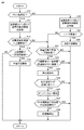
図5は、制御装置100が冷媒量調整および冷媒不足検出を行う際の処理手順の一例を示すフローチャートである。
(Flow of control for adjusting the amount of refrigerant and detecting refrigerant shortage)
FIG. 5 is a flowchart showing an example of a processing procedure when the control device 100 adjusts the amount of refrigerant and detects a shortage of refrigerant.
制御装置100は、圧縮機10の吐出圧PHが臨界圧を超えているか否かを判定する(ステップS10)。圧縮機10の吐出圧PHが臨界圧を超えている超臨界状態である場合(ステップS10においてYES)、制御装置100は、上述したように、外気温TAと凝縮器20の出口の冷媒温度T1との温度差ΔT1を用いて流量調整弁72の開度を制御する(ステップS11)。たとえば、温度差ΔT1が大きい場合、制御装置100は、温度差ΔT1の大きさに応じて流量調整弁72の開度を大きくする。
The control device 100 determines whether or not the discharge pressure PH of the compressor 10 exceeds the critical pressure (step S10). When the discharge pressure PH of the compressor 10 is in a supercritical state exceeding the critical pressure (YES in step S10), the control device 100 has the outside air temperature TA and the refrigerant temperature T1 at the outlet of the condenser 20 as described above. The opening degree of the flow rate adjusting valve 72 is controlled by using the temperature difference ΔT1 with and from (step S11). For example, when the temperature difference ΔT1 is large, the control device 100 increases the opening degree of the flow rate adjusting valve 72 according to the magnitude of the temperature difference ΔT1.
次いで、制御装置100は、流量調整弁72の開度が上限開度であるか否かを判定する(ステップS12)。流量調整弁72の開度が上限開度でない場合(ステップS12においてNO)、制御装置100は、処理をステップS22に移す。
Next, the control device 100 determines whether or not the opening degree of the flow rate adjusting valve 72 is the upper limit opening degree (step S12). When the opening degree of the flow rate adjusting valve 72 is not the upper limit opening degree (NO in step S12), the control device 100 shifts the process to step S22.
一方、流量調整弁72の開度が上限開度である場合(ステップS12においてYES)、制御装置100は、流量調整弁72の開度が上限開度である状態が一定時間継続したか否かを判定する(ステップS14)。流量調整弁72の開度が上限開度である状態が一定時間継続していない場合(ステップS14においてNO)、制御装置100は、以降の処理をスキップしてリターンへと処理を移す。
On the other hand, when the opening degree of the flow rate adjusting valve 72 is the upper limit opening (YES in step S12), the control device 100 determines whether or not the state in which the opening degree of the flow rate adjusting valve 72 is the upper limit opening continues for a certain period of time. Is determined (step S14). When the state in which the opening degree of the flow rate adjusting valve 72 is the upper limit opening degree does not continue for a certain period of time (NO in step S14), the control device 100 skips the subsequent processing and shifts the processing to the return.
流量調整弁72の開度が上限開度である状態が一定時間継続した場合(ステップS14においてYES)、制御装置100は、冷媒回路全体の冷媒が不足していると判定し、判定結果を使用者へ報知するように報知装置150を制御する(ステップS16)。
When the state in which the opening degree of the flow rate adjusting valve 72 is the upper limit opening continues for a certain period of time (YES in step S14), the control device 100 determines that the refrigerant in the entire refrigerant circuit is insufficient, and uses the determination result. The notification device 150 is controlled so as to notify the person (step S16).
一方、圧縮機10の吐出圧PHが臨界圧を超えていない通常状態である場合(ステップS10においてNO)、制御装置100は、上述したように、凝縮器20の出口の冷媒温度T1と熱交換器30の出口温度T2の差から熱交換器30の温度効率εを算出し、算出された温度効率εに応じて流量調整弁72を制御する(ステップS20)。
On the other hand, when the discharge pressure PH of the compressor 10 is in a normal state where the discharge pressure PH does not exceed the critical pressure (NO in step S10), the control device 100 exchanges heat with the refrigerant temperature T1 at the outlet of the condenser 20 as described above. The temperature efficiency ε of the heat exchanger 30 is calculated from the difference in the outlet temperature T2 of the vessel 30, and the flow rate adjusting valve 72 is controlled according to the calculated temperature efficiency ε (step S20).
次いで、制御装置100は、算出された温度効率εが下限値未満であるか否かを判定する(ステップS21)。温度効率εが下限値未満である場合(ステップS21においてYES)、制御装置100は、冷媒回路全体の冷媒が不足していると判定し、判定結果を使用者へ報知するように報知装置150を制御する(ステップS40)。
Next, the control device 100 determines whether or not the calculated temperature efficiency ε is less than the lower limit value (step S21). When the temperature efficiency ε is less than the lower limit value (YES in step S21), the control device 100 determines that the refrigerant in the entire refrigerant circuit is insufficient, and causes the notification device 150 to notify the user of the determination result. Control (step S40).
一方、温度効率εが下限値未満ではない場合(ステップS21においてNO)、制御装置100は、処理をステップS22に移す。
On the other hand, when the temperature efficiency ε is not less than the lower limit value (NO in step S21), the control device 100 shifts the process to step S22.
ステップS22において、制御装置100は、流量調整弁72の開度が下限開度であるか否かを判定する。流量調整弁72の開度が下限開度でない場合(ステップS22においてNO)、制御装置100は、以降の処理をスキップしてリターンへと処理を移す。
In step S22, the control device 100 determines whether or not the opening degree of the flow rate adjusting valve 72 is the lower limit opening degree. When the opening degree of the flow rate adjusting valve 72 is not the lower limit opening degree (NO in step S22), the control device 100 skips the subsequent processing and shifts the processing to the return.
流量調整弁72の開度が下限開度である場合(ステップS22においてYES)、制御装置100は、流量調整弁72の開度が下限開度である状態が一定時間継続した後も、圧縮機10の吐出圧PHが閾値よりも大きいか否かを判定する(ステップS24)。なお、ステップS24で用いられる「閾値」は、たとえば臨界圧よりも低い値に設定される。流量調整弁72の開度が下限開度である状態が一定時間継続していない場合、あるいは、圧縮機10の吐出圧PHが閾値未満である場合(ステップS24においてNO)、制御装置100は、以降の処理をスキップしてリターンへと処理を移す。
When the opening degree of the flow rate adjusting valve 72 is the lower limit opening (YES in step S22), the control device 100 is a compressor even after the state in which the opening degree of the flow rate adjusting valve 72 is the lower limit opening continues for a certain period of time. It is determined whether or not the discharge pressure PH of 10 is larger than the threshold value (step S24). The "threshold value" used in step S24 is set to a value lower than, for example, the critical pressure. When the state in which the opening degree of the flow rate adjusting valve 72 is the lower limit opening degree does not continue for a certain period of time, or when the discharge pressure PH of the compressor 10 is less than the threshold value (NO in step S24), the control device 100 determines. The subsequent processing is skipped and the processing is moved to the return.
流量調整弁72の開度が下限開度である状態が一定時間継続した後も、圧縮機10の吐出圧PHが閾値よりも大きい場合(ステップS24においてYES)、制御装置100は、冷媒回路が過充填状態であると判定し、判定結果を使用者へ報知するように報知装置150を制御する(ステップS26)。
If the discharge pressure PH of the compressor 10 is larger than the threshold value even after the state in which the opening degree of the flow rate adjusting valve 72 is the lower limit opening degree continues for a certain period of time (YES in step S24), the refrigerant circuit of the control device 100 has a refrigerant circuit. The notification device 150 is controlled so as to determine that the overfilled state is present and notify the user of the determination result (step S26).
過充填状態と判定された後、制御装置100は、圧縮機10の吐出温度THが急激に低下しているか否か、具体的には、圧縮機10の吐出温度THの低下速度の大きさが基準値よりも大きいか否かを判定する(ステップS28)。そして、制御装置100は、吐出温度THの低下速度の大きさが基準値よりも大きい場合、すなわち吐出温度THが急激に低下している場合、受液器73が液冷媒で満たされているオーバーフロー状態であると判定し、判定結果を使用者へ報知するように報知装置150を制御する(ステップS30)。
After the determination of the overfilled state, the control device 100 determines whether or not the discharge temperature TH of the compressor 10 is rapidly reduced, specifically, the magnitude of the rate of decrease of the discharge temperature TH of the compressor 10. It is determined whether or not it is larger than the reference value (step S28). Then, in the control device 100, when the magnitude of the decrease rate of the discharge temperature TH is larger than the reference value, that is, when the discharge temperature TH is rapidly decreased, the receiver 73 is filled with the liquid refrigerant. The notification device 150 is controlled so as to determine that the state is in the state and notify the user of the determination result (step S30).
オーバーフロー状態であると判定された後、制御装置100は、圧縮機10の吐出温度THと圧縮機10の吐出圧PHにおける飽和温度との差である吐出過熱度が圧縮機10の仕様範囲内に収まっているか否かを判定する(ステップS32)。吐出過熱度が圧縮機10の仕様範囲内に収まっている場合(ステップS32においてNO)、制御装置100は、以降の処理をスキップしてリターンへと処理を移す。一方、吐出過熱度が圧縮機10の仕様範囲内に収まっていない場合(ステップS32においてYES)、制御装置100は、圧縮機10を停止させる(ステップS34)。
After determining that the overflow state is determined, the control device 100 determines that the discharge superheat degree, which is the difference between the discharge temperature TH of the compressor 10 and the saturation temperature at the discharge pressure PH of the compressor 10, is within the specification range of the compressor 10. It is determined whether or not it fits (step S32). When the discharge superheat degree is within the specification range of the compressor 10 (NO in step S32), the control device 100 skips the subsequent processing and shifts the processing to the return. On the other hand, when the discharge superheat degree is not within the specification range of the compressor 10 (YES in step S32), the control device 100 stops the compressor 10 (step S34).
以上のように、本実施の形態による制御装置100は、通常状態である運転条件では、熱交換器30の温度効率εを用いて、冷媒不足の有無を判定する。一方、超臨界状態である運転条件では、制御装置100は、熱交換器30の温度効率εを用いるのではなく、外気温TAと凝縮器20の出口の冷媒温度T1との温度差ΔT1に応じてフィードバック制御される「流量調整弁72の開度」を用いて、冷媒不足の有無を判定する。このように冷媒不足の判定方法を切り替えることで、超臨界状態である運転条件下でも冷媒回路の冷媒不足の有無を適切に判定することができる。その結果、超臨界状態となり得る冷媒が用いられる冷凍サイクル装置1において、通常状態および超臨界状態を含めたすべての運転範囲で冷媒不足の有無を判定できるようになる。
As described above, the control device 100 according to the present embodiment determines the presence or absence of refrigerant shortage by using the temperature efficiency ε of the heat exchanger 30 under the operating conditions under the normal state. On the other hand, under the operating conditions in the supercritical state, the control device 100 does not use the temperature efficiency ε of the heat exchanger 30, but responds to the temperature difference ΔT1 between the outside air temperature TA and the refrigerant temperature T1 at the outlet of the condenser 20. The presence or absence of a refrigerant shortage is determined by using the “opening of the flow rate adjusting valve 72” which is feedback-controlled. By switching the method for determining the refrigerant shortage in this way, it is possible to appropriately determine the presence or absence of the refrigerant shortage in the refrigerant circuit even under operating conditions in a supercritical state. As a result, in the refrigeration cycle apparatus 1 in which a refrigerant that can be in a supercritical state is used, it becomes possible to determine the presence or absence of a refrigerant shortage in the entire operating range including the normal state and the supercritical state.
なお、上述の実施の形態においては冷凍サイクル装置1を備える冷凍機を例示して説明したが、冷凍サイクル装置1は空気調和機などに利用されても良い。
Although the refrigerator provided with the refrigeration cycle device 1 has been described as an example in the above-described embodiment, the refrigeration cycle device 1 may be used as an air conditioner or the like.
今回開示された実施の形態はすべての点で例示であって制限的なものではないと考えられるべきである。本開示の範囲は上記した説明ではなくて請求の範囲によって示され、請求の範囲と均等の意味および範囲内でのすべての変更が含まれることが意図される。
The embodiments disclosed this time should be considered to be exemplary in all respects and not restrictive. The scope of the present disclosure is indicated by the scope of claims rather than the above description, and is intended to include all modifications within the meaning and scope of the claims.