WO2021192285A1 - 薬液注入針および薬液注入針システム - Google Patents
薬液注入針および薬液注入針システム Download PDFInfo
- Publication number
- WO2021192285A1 WO2021192285A1 PCT/JP2020/014253 JP2020014253W WO2021192285A1 WO 2021192285 A1 WO2021192285 A1 WO 2021192285A1 JP 2020014253 W JP2020014253 W JP 2020014253W WO 2021192285 A1 WO2021192285 A1 WO 2021192285A1
- Authority
- WO
- WIPO (PCT)
- Prior art keywords
- electrode
- injection needle
- drug solution
- metal tube
- myocardium
- Prior art date
- Legal status (The legal status is an assumption and is not a legal conclusion. Google has not performed a legal analysis and makes no representation as to the accuracy of the status listed.)
- Ceased
Links
Images






Classifications
-
- A—HUMAN NECESSITIES
- A61—MEDICAL OR VETERINARY SCIENCE; HYGIENE
- A61M—DEVICES FOR INTRODUCING MEDIA INTO, OR ONTO, THE BODY; DEVICES FOR TRANSDUCING BODY MEDIA OR FOR TAKING MEDIA FROM THE BODY; DEVICES FOR PRODUCING OR ENDING SLEEP OR STUPOR
- A61M5/00—Devices for bringing media into the body in a subcutaneous, intra-vascular or intramuscular way; Accessories therefor, e.g. filling or cleaning devices, arm-rests
- A61M5/14—Infusion devices, e.g. infusing by gravity; Blood infusion; Accessories therefor
- A61M5/158—Needles for infusions; Accessories therefor, e.g. for inserting infusion needles, or for holding them on the body
Definitions
- the present invention relates to a drug solution injection needle for puncturing a patient's myocardium and injecting a drug solution, and a drug solution injection needle system including such a drug solution injection needle.
- a treatment method for regenerating cardiomyocytes has been performed by directly administering a drug solution such as a myocardial regenerating cell preparation to cardiomyocytes that are losing their functions due to myocardial infarction or the like.
- a drug solution such as a myocardial regenerating cell preparation
- cardiomyocytes that are losing their functions due to myocardial infarction or the like.
- mapping with an electrophysiology (EP) catheter or the like is performed in order to identify a target site requiring medication treatment prior to treatment.
- This drug solution injection needle is introduced into the living body cavity (heart chamber) while being inserted into the sheath or guiding catheter, and the needle tip of the drug solution injection needle is projected from the tip opening of the sheath or guiding catheter to project the target site. (Myocardium) is punctured and the drug solution is administered to the cardiomyocytes at the target site.
- an opening for injecting a drug solution is formed in the myocardium. Must be located.
- the needle tip penetrates the heart wall by pushing the drug solution injection needle, and the opening is located outside the heart wall (thoracic cavity). In such cases, not only is it impossible to inject the drug solution into the myocardium, but blood may accumulate in the sac and cause cardiac tamponade.
- An object of the present invention is that it is possible to easily determine whether or not the opening for injecting a drug solution is located inside the heart wall (myocardium), and the drug solution can be reliably injected into the myocardium.
- the purpose is to provide a drug solution injection needle.
- Another object of the present invention is to provide a drug solution injection needle capable of detecting that the needle tip has penetrated the heart wall and preventing the onset of cardiac tamponade.
- Yet another object of the present invention is to provide a drug solution injection needle system capable of reliably injecting a drug solution into the myocardium.
- the drug solution injection needle of the present invention is a hollow needle for puncturing the myocardium of a patient and injecting the drug solution.
- a first electrode for potential measurement which is made of a sharp metal member with a closed tip, and An electrically insulating connecting tube connected to the base end side of the first electrode and A metal pipe connected to the base end side of the connecting pipe and An insulating coating layer that covers the outer peripheral surface of the base end portion of the metal tube is provided.
- the tube wall of the connecting pipe has at least one side hole (outflow path of the chemical solution) that communicates with the lumen of the needle (the lumen of the connecting pipe) and opens on the outer peripheral surface of the connecting pipe.
- a second electrode for potential measurement is formed by a tip portion of the metal tube that is not coated on the insulating coating layer.
- the drug solution injection needle having such a configuration, when the first electrode is introduced from the heart chamber into the inside of the heart wall (myocardium), the potential measured by the first electrode in contact with the myocardial tissue suddenly increases. Rise (high potential can be obtained). Therefore, it can be confirmed that the first electrode has been introduced into the myocardium by detecting a rapid rise in the potential (acquiring a high potential). Also, when the second electrode is introduced from the heart chamber to the inside of the heart wall (myocardium), the potential measured by the second electrode in contact with the myocardial tissue rises sharply (acquires a high potential). be able to).
- the second electrode has been introduced into the myocardium by detecting a rapid rise in the potential (acquiring a high potential). Further, since the connecting tube is located between the first electrode and the second electrode, when both the first electrode and the second electrode are located in the myocardium, the side hole formed in the tube wall of the connecting tube The opening (the opening for injecting the drug solution) is always located in the myocardium.
- the opening of the side hole (opening for injecting the chemical solution) formed in the tube wall of the connecting tube is opened. It can be determined that it is located in the myocardium, and by confirming that both potentials are equal to or higher than the predetermined values and performing the injection operation of the drug solution, the drug solution is surely injected into the myocardium from the opening of the side hole. Can be infused.
- the second electrode when only the potential measured by the first electrode is equal to or higher than a predetermined value (only the first electrode is in contact with the myocardial tissue), the second electrode is placed in the heart chamber outside the heart wall. It is located and may have at least the proximal end of the connecting tube located in the heart chamber of the heart wall.
- the first electrode is located in the thoracic cavity outside the heart wall.
- At least the tip of the connecting tube may be located in the thoracic cavity.
- the chemical injection needle having such a configuration, when the first electrode made of a sharp metal member penetrates the heart wall and becomes non-contact with the myocardial tissue, the potential measured by the first electrode is obtained. Can detect this state by rapidly dropping, so the potential measured by the first electrode is monitored, and when this measured potential drops sharply and falls below a predetermined value, the needle is moved. By pulling back, the onset of cardiac tamponade can be avoided.
- the tip portion of the metal tube is used as the second electrode by providing the metal tube and the insulating coating layer covering the outer peripheral surface of the base end portion thereof. And the base end portion of the metal tube can be used as a lead for the second electrode.
- the needle is connected to the first electrode and extends in the proximal direction on the connecting tube and the outer peripheral surface of the metal tube while ensuring insulation against the metal tube.
- the lead of the first electrode (insulation coating lead) can be formed by the band-shaped conductive layer and the band-shaped insulating layer. Further, since it is not necessary to provide the lead wire of the first electrode inside the metal tube, a sufficient space for the lumen of the needle can be secured.
- a band-shaped insulating base layer is formed in the formation region of the conductive layer on the outer peripheral surface (exposed metal surface) of the metal tube that is not coated with the insulating coating layer. Is preferable.
- the insulating property between the band-shaped conductive layer forming the lead of the first electrode and the metal tube forming the second electrode or the lead thereof is interposed between the two. It can be secured by the insulating base layer.
- the length of the first electrode is preferably 0.5 to 5 mm. According to the chemical injection needle having such a structure, good puncture performance can be exhibited because the length of the first electrode is 0.5 mm or more. Further, when the length of the first electrode is 5 mm or less, all of the first electrode, the connecting tube and the second electrode can be embedded in the myocardium, and the drug solution injection needle is pushed forward to push the needle tip (the needle tip ( When the first electrode) penetrates the heart wall, this state can be quickly sensed, and by grasping this state and pulling back the needle, the onset of cardiac tamponade can be reliably prevented.
- a group of side holes in which a plurality of the side holes are arranged along the axial direction of the connecting pipe are spaced at equal angles along the circumferential direction of the connecting pipe. It is preferable that they are arranged.
- the drug solution injection needle having such a configuration the drug solution can be injected evenly in the axial direction of the connecting tube (the wall thickness direction of the myocardium) and the circumferential direction of the connecting tube.
- the side hole located on the distal end side in the group of the lateral holes has a diameter larger than that of the lateral hole located on the proximal end side. ..
- the drug solution injection needle having such a configuration the drug solution can be injected more evenly in the axial direction of the connecting tube (the wall thickness direction of the myocardium).
- a spiral slit is formed in the tip region of the base end portion of the metal tube.
- the rigidity in the tip region of the base end portion of the metal tube can be lowered to some extent by forming the spiral slit, so that the injection needle can be made flexible. ..
- the drug solution injection needle of the present invention it is preferable that the drug solution is a myocardial regenerating cell preparation.
- the chemical injection needle system of the present invention includes the chemical injection needle of the present invention.
- the drug solution can be injected into the myocardium (injection operation is permitted). It is characterized in that it is provided with a notification means for notifying the operator.
- the opening of the side hole (opening for chemical injection) formed in the tube wall of the connecting tube is opened. It can be easily determined whether or not it is located inside the heart wall (myocardium), whereby the drug solution can be reliably injected into the myocardium of the patient.
- the potential measured by the first electrode it is possible to grasp that the first electrode has penetrated the heart wall and is in a non-contact state with the myocardial tissue, and this state can be grasped. By pulling back the needle, it is possible to prevent the onset of cardiac tamponade.
- the measurement potential by the first electrode and the measurement potential by the second electrode are not constantly monitored by a monitor or the like by performing the drug solution injection operation after waiting for the notification from the notification means.
- the drug solution can be reliably injected into the myocardium of the patient.
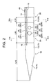
- FIG. 2 is a cross-sectional view taken along the line VA-VA of FIG.
- FIG. 3 is a sectional view taken along line VC-VC of FIG.
- FIG. 3 is a cross-sectional view taken along the line VD-VD of FIG. It is explanatory drawing which shows the state which a part of the 1st electrode and a part of the connecting tube which make up the chemical solution injection needle shown in FIG. 1 is introduced into the myocardium. It is explanatory drawing which shows the state which a part of the 1st electrode, the connecting tube and a part of the 2nd electrode which make up the chemical solution injection needle shown in FIG. 1 is introduced into the myocardium. It is explanatory drawing which shows the state which the 1st electrode, the connecting tube and the 2nd electrode which make up the chemical solution injection needle shown in FIG. 1 are introduced into the myocardium.
- the drug solution injection needle 100 of this embodiment shown in FIGS. 1 to 5 is a hollow needle for piercing the myocardial layer of a patient and injecting the drug solution into myocardial cells, and has a tip.
- a first electrode 10 for measuring potential which is made of a closed sharp metal member, an electrically insulating connecting tube 20 connected to the proximal end side of the first electrode 10, and a connecting tube 20 connected to the proximal end side of the connecting tube 20.
- the metal tube 30 is provided with an insulating coating layer 40 that covers the outer peripheral surface of the base end portion 32 of the metal tube 30, and the tube wall of the connecting tube 20 communicates with the lumen of the chemical injection needle 100 and is connected.
- Ten side holes 25 (251 to 259, 25X) opened on the outer peripheral surface of 20 are formed, and the tip portion of the metal tube 30 in which the metal surface is exposed without being covered with the insulating layer 40 provides a first portion for potential measurement.
- Two electrodes 31 are configured, and the connecting tube 20 and the metal tube 30 are connected to the first electrode 10 on the outer peripheral surfaces of the connecting tube 20 and the metal tube 30, and the outer peripheral surfaces of the connecting tube 20 and the metal tube 30 are insulated from the metal tube 30.
- a band-shaped conductive layer 15 extending toward the base end while securing and reaching the base end of the chemical injection needle 100 and a band-shaped insulating layer 16 covering the surface of the conductive layer 15 are formed, and the conductive layer 15 with respect to the metal tube 30 is formed.
- the outer peripheral surface of the metal tube 30 in which the metal surface is exposed without being covered with the insulating coating layer 40 (the outer peripheral surface of the second electrode 31 and the outer peripheral surface of the proximal region of the proximal portion 32).
- a band-shaped insulating base layer 17 is formed in the forming region of the conductive layer 15 in the above.
- the chemical injection needle 100 of this embodiment includes a first electrode 10 made of a metal member, an electrically insulating connecting tube 20, a metal tube 30, and an insulating coating layer 40.
- a grip portion 50 is attached to the proximal end side of the metal tube 30 constituting the chemical solution injection needle 100, and the chemical solution injection needle device is configured by the chemical solution injection needle 100 and the grip portion 50. There is.
- the grip portion 50 constituting the chemical injection needle device is made of resin, rubber, elastomer or the like.
- the grip portion 50 is provided with an injection port 51 for supplying the drug solution to the lumen of the drug solution injection needle 100.
- a connector 53 is attached to the grip portion 50, and the connector 53 is electrically connected to the second electrode 31 via a lead wire joined to the base end of the metal tube 30, and is conductive. It is electrically connected to the first electrode 10 via a lead wire joined to the base end of the layer 15.
- the effective length of the chemical injection needle 100 (L100 shown in FIG. 1) protruding from the tip of the grip portion 50 is usually 800 to 2500 mm, and a suitable example is 1300 mm.
- the outer diameter of the chemical injection needle 100 is usually 0.3 to 1.5 mm, and a suitable example is 0.8 mm.
- the inner diameter of the chemical injection needle 100 is usually 0.1 to 1.3 mm, and a suitable example is 0.6 mm.
- the drug solution injection needle 100 of the present embodiment is a hollow needle for puncturing the myocardium of a patient and injecting the drug solution into cardiomyocytes.
- examples of the "drug solution” include cell preparations such as myocardial regenerative cell preparations and gene transfer agents.
- the first electrode 10 constituting the chemical injection needle 100 is composed of a metal member composed of a solid sharp portion 11 and a tubular portion 12 having an internal space, and the tip of the metal member. Is blocked.
- the length of the first electrode 10 (L10 shown in FIG. 2) is usually 0.5 to 5 mm, and a suitable example is 2.5 mm.
- the puncture performance may be impaired or the joint strength with the connecting tube 20 may be lowered.
- the length of the first electrode 10 is too long, the blood vessel followability of the drug solution injection needle 100 is impaired, or the first electrode, the connecting tube 20, and the second electrode 31 (the tip of the metal tube 30) are impaired. Part) may be difficult to implant in the myocardium. Further, if the length of the first electrode 10 is too long, it becomes difficult to quickly detect that the first electrode 10 has penetrated the heart wall.
- metal constituting the first electrode 10 all conventionally known metals can be used as the metal constituting the chemical injection needle, and examples thereof include stainless steel, NiTi, ⁇ titanium, and platinum iridium.
- a part or all of the first electrode 10 may be made of a radiation opaque metal, whereby the position of the first electrode 10 up to the target portion can be confirmed by a cine image.
- the radiation opaque metal include platinum and its alloys, gold, tungsten, tantalum and the like.
- the connecting tube 20 constituting the chemical injection needle 100 is made of an electrically insulating material, and is a member that connects the first electrode 10 and the metal tube 30 while ensuring the electrical insulating property of both.
- the mode of connecting the first electrode 10 and the metal tube 30 via the connecting tube 20 is not particularly limited, but in the present embodiment, as shown in FIG. 4, the tip side small diameter of the connecting tube 20 is small.
- the portion 21 into the internal space of the first electrode 10 (tubular portion 12) and inserting the proximal end side small diameter portion 22 of the connecting tube 20 into the tip opening of the metal tube 30, the first electrode 10 and the metal It is connected to the pipe 30.
- the lumen of the connecting tube 20 and the lumen of the metal tube 30 communicate with each other to form the lumen of the drug solution injection needle 100.
- the length of the connecting pipe 20 (L20 shown in FIG. 2) is usually 0.1 to 25 mm, and a suitable example is 14 mm.
- the first electrode 10 and the metal tube 30 may not be sufficiently insulated.
- the length of the connecting pipe 20 is too long, the blood vessel followability at the tip portion of the drug solution injection needle 100 may be impaired.
- the electrically insulating material constituting the connecting pipe 20 is not particularly limited, but a resin material and a ceramic material are preferable, and the resin material is selected because it has good electrical insulation and heat insulating properties and is easy to mold. It is particularly preferable to use it.
- the resin constituting the connecting pipe 20 may be a thermoplastic resin or a thermosetting resin.
- the resin includes ebonite. Specifically, cyclic olefin resin, polyphenylene sulfide, polyetheretherketone (PEEK), polybutylene terephthalate, polycarbonate, polyamide, polyacetal, modified polyphenylene ether, polyester resin, polytetrafluoroethylene, fluorine resin, sulfone type.
- polyetheretherketone, polycarbonate, polyphenylsulfone, polyamide, polyacetal and the like are preferable.
- the connecting pipe 20 has 10 side holes that communicate with the lumen of the chemical injection needle 100 (the lumen of the connecting pipe 20) and open on the outer peripheral surface of the connecting pipe 20 as an outflow path for the chemical liquid to be injected. 25 (251) ⁇ 259,25X) is formed.
- the side hole group and the fourth side hole group formed by the side holes 259 and 25X are arranged at equal angles (90 °) along the circumferential direction of the connecting pipe 20.
- the drug solution can be injected evenly in the axial direction of the connecting tube 20 (the wall thickness direction of the myocardium) and the circumferential direction of the connecting tube 20.
- the side hole 251 located on the tip side has the largest diameter
- the side hole 252 located in the middle next has a large diameter
- the side hole 253 located on the base end side has a large diameter. It is the minimum.
- the diameter of each side hole in the second side hole group is larger than that of the side hole 254 located on the distal end side and the side hole 255 located on the proximal end side.
- the side hole 256 located on the tip side is the largest
- the side hole 257 located in the middle is the next largest
- the side hole 258 located on the base end side is large. It is the minimum.
- each side hole in the fourth side hole group is larger than the side hole 25X in which the side hole 259 located on the distal end side is located on the proximal end side.
- the amount of the chemical solution discharged is equalized among the side holes in the same side hole group. It is possible to inject the drug solution more evenly in the axial direction of the connecting tube 20 (the wall thickness direction of the myocardium).
- the side hole 251 and the side hole 256 are 0.27 mm
- the side hole 252 and the side hole 257 are 0.23 mm
- the side hole 253 and the side hole 258 are 0.20 mm
- the side hole 254 and the side hole 259 are 0.30 mm
- the side hole 255 and the side hole 25X are 0.25 mm.
- the metal tube 30 constituting the chemical injection needle 100 is made of a tubular member having a lumen communicating with the lumen of the connecting tube 20.
- the length (L100-L10-L20) of the metal tube 30 is usually 800 to 2500 mm, and a suitable example is 1283.5 mm (1300 mm-2.5 mm-14 mm).
- the metal tube 30 is required to have the rigidity (particularly flexural rigidity) and elasticity (particularly bending elasticity) required for a normal chemical injection needle.
- Examples of the metal constituting the metal tube 30 include the same metal as the first electrode 10.
- a part or all of the tip portion of the metal tube 30 may be made of a radiation opaque metal, whereby the position of the second electrode 31 up to the target portion can be confirmed by a cine image. ..
- a spiral slit 33 is formed in the tip region of the proximal end portion 32 of the metal tube 30.
- the rigidity of the metal tube 30 in the tip region is weakened to some extent to impart flexibility (flexibility), and the chemical injection needle 100 has excellent blood vessel followability and can easily form a blood vessel shape to reach the target site. Can be made to follow.
- the slit 33 is a through slit extending from the outer peripheral surface to the inner peripheral surface of the metal tube, but the slit may be formed so as not to reach the inner peripheral surface.
- the length of the slit 33 (L33 shown in FIG. 1) formed in the tip region of the base end portion 32 is usually 30 to 400 mm, and a suitable example is 100 mm.
- the pitch of the slits 33 is formed so as to be continuously narrowed toward the tip end.
- the rigidity of the tip region of the proximal end portion 32 can be continuously (smoothly) lowered toward the tip end direction, thereby improving the operability when introducing the chemical solution injection needle 100 to the target site. be able to.
- all the slits formed in the tip region of the proximal end portion may be formed at the same pitch.
- the slit 33 formed in the metal tube 30 coated on the insulating coating layer 40 is shown by a solid line instead of a broken line.
- the insulating coating layer 40 constituting the chemical injection needle 100 is a layer made of an electrically insulating material that covers the outer peripheral surface of the base end portion 32 of the metal tube 30. Since the outer peripheral surface of the base end portion 32 of the metal tube 30 is covered with the insulating coating layer 40, the tip portion of the metal tube 30 not covered by the insulating coating layer 40 functions as a second electrode 31 for potential measurement. At the same time, the base end portion 32 of the metal tube 30 functions as a lead of the second electrode 31. As a result, it is not necessary to separately provide a ring-shaped electrode on the outer surface of the needle or to provide a lead wire for the electrode inside or outside the metal tube, so that the diameter of the chemical injection needle 100 can be reduced. , A sufficient lumen space can be secured.
- the insulating coating layer 40 can close the slit 33 formed in the tip region of the base end portion 32 of the metal tube 30, and the liquidtightness of the chemical injection needle 100 can be ensured.
- the length of the tip portion of the metal tube 30 that functions as the second electrode 31 is usually 0.1 to 4 mm (0.007 to 0.3% of the total length of the metal tube 30). Degree), and a suitable example is 0.5 mm.
- the insulating coating layer 40 does not need to cover the outer peripheral surface of the base end portion 32 of the metal tube 30 over the entire length (L100-L10-L20-L31), and in the present embodiment, it is constant from the tip of the base end portion 32.
- the tip region over the length is covered with the insulating coating layer 40.
- the length of the tip region (L40 shown in FIG. 1) covered by the insulating coating layer 40 is usually 60 to 420 mm, and a suitable example is 120 mm.
- the insulating coating layer 40 can be formed by shrinking the heat-shrinkable resin tube in which the base end portion 32 of the metal tube 30 is inserted inside.
- the heat-shrinkable resin tube for forming the insulating coating layer 40 include polyethylene terephthalate (PET), a polyether blockamide copolymer resin (PEBAX (registered trademark)), and the like.
- the film thickness of the insulating coating layer 40 is, for example, 10 to 100 ⁇ m, and a suitable example is 20 ⁇ m.
- the drug solution injection needle 100 of the present embodiment and the grip portion 50 constitute a drug solution injection needle device, and the drug solution injection needle device injects the drug solution into the myocardium of the patient.
- a syringe filled with the drug solution to be supplied to the cavity of the drug solution injection needle 100 is connected to the injection port 51, and the connector 53 is connected to the electrocardiograph.
- the chemical injection needle 100 extends in the axial direction on the outer peripheral surfaces of the connecting pipe 20 and the metal pipe 30 while ensuring insulation with respect to the metal pipe 30.
- a band-shaped conductive layer 15 is formed up to the base end of the above.
- the tip of the conductive layer 15 is electrically connected to the first electrode 10, and the lead wire of the connector 53 is joined to the base end of the conductive layer 15.
- the thickness of the conductive layer 15 is, for example, 10 to 100 ⁇ m.
- the constituent materials of the conductive layer 15 include silver, gold, platinum, copper, tin, bismuth and lead.
- the method for forming the conductive layer 15 is not particularly limited, but it can be preferably formed by, for example, an aerosol jet printing method or the like.
- the surface of the conductive layer 15 formed on the outer peripheral surfaces of the connecting tube 20 and the metal tube 30 is covered with a band-shaped insulating layer 16, and the lead of the first electrode 10 (insulated coated lead) is formed by the conductive layer 15 and the insulating layer 16. Is configured.
- the thickness of the insulating layer 16 is, for example, 10 to 100 ⁇ m.
- Examples of the constituent material of the insulating layer 16 include epoxy resin, urethane resin, polyimide resin, fluorine-based resin such as PTFE and PFA, acrylate-based resin, silicone-based resin, polyamide-based resin, PET, PEEK, and PES. can.
- an insulating coating layer 40 is provided on the outer peripheral surface of the second electrode 31 (the tip end portion of the metal tube 30) and the outer peripheral surface of the proximal end region of the proximal end portion 32 of the metal tube 30. Since the metal is not formed and the metal is exposed, a band-shaped insulating base layer 17 is formed in the formed region of the conductive layer 15 on these outer peripheral surfaces (the conductive layer 15 is formed on the surface of the insulating base layer 17). Is formed). As a result, the conductive layer 15 (lead of the first electrode 10) and the metal tube 30 (lead of the second electrode 31 and the second electrode 31) can be electrically insulated.
- the thickness of the insulating base layer 17 is, for example, 10 to 500 ⁇ m. Examples of the constituent material of the insulating base layer 17 include the same constituent materials as those of the insulating layer 16.
- the method for forming the insulating layer 16 and the insulating base layer 17 is not particularly limited, but can be suitably formed by, for example, aerosol jet printing or the like.
- the lead wire of the first electrode 10 through which the inside of the metal tube 30 is inserted is provided. Since it is not necessary, a sufficient space for the cavity of the needle can be secured.
- the drug solution injection needle 100 of the present embodiment is introduced into the living body cavity (heart chamber) in a state of being inserted into a sheath or a guiding catheter. Then, the needle tip of the drug solution injection needle 100 is projected from the tip opening of the sheath or the guiding catheter, punctured into the target site (myocardium) specified by mapping, and the drug solution is administered to the cardiomyocytes at the target site.
- the target site myocardium
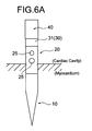
- FIG. 6A shows a state in which the drug solution injection needle 100 is punctured into the myocardium and a part (tip portion) of the first electrode 10 and the connecting tube 20 is introduced into the inside of the heart wall (myocardium).
- the rest (base end portion) of the connecting tube 20 including the region where the side hole 25 is formed is located in the heart chamber, so that even if the drug solution is injected at this stage, it leaks into the heart chamber. It comes out and the drug solution cannot be injected into the myocardium.
- the second electrode 31 (the tip portion of the metal tube 30) is in the heart chamber. Since it is located inside, such a high potential is not acquired by the second electrode 31. Then, at this stage where the high potential is acquired only by the first electrode 10, the operator does not perform the injection operation of the chemical solution.
- a high potential for example, 2 mV or more
- the drug solution injection needle 100 is pushed forward from the state shown in FIG. 6A, the first electrode 10 and the connecting tube 20 are completely buried inside the heart wall (myocardium), and the second electrode 31 (metal tube). A part of the tip portion of 30) is introduced into the inside of the heart wall (myocardium).
- the connecting tube 20 in which the side hole 25 is formed is located in the myocardium. Therefore, if the drug solution is injected at this stage, the drug solution can be injected into the myocardium.
- the potential measured by the second electrode 31 introduced into the myocardium rapidly rises, and a high potential (for example, 2 mV or more) is also acquired by the second electrode 31.
- the operator who confirms that the measured potential by the first electrode 10 and the measured potential by the second electrode 31 are both equal to or higher than a predetermined value (for example, 2 mV) by a monitor of an electrometer or the like performs the injection operation of the drug solution.
- a predetermined value for example, 2 mV
- the drug solution 90 can be reliably injected into the myocardium of the patient through the opening of the side hole 25 (opening for drug solution injection) formed in the connecting tube 20.
- FIG. 6C shows a state in which the first electrode 10, the connecting tube 20, and the second electrode 31 (the tip portion of the metal tube 30) constituting the chemical injection needle 100 are introduced into the inside of the heart wall (myocardium). There is. Even in this state, both the measurement potential of the first electrode 10 and the measurement potential of the second electrode 31 are equal to or higher than a predetermined value.
- the drug solution 90 can be reliably injected into the myocardium of the patient through the opening of the side hole 25 (opening for injecting the drug solution).
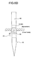
- the drug solution injection needle 100 is pushed forward from the state shown in FIG. 6C, the needle tip penetrates the heart wall, and a part (tip portion) of the first electrode 10 and the connecting tube 20 is outside the heart wall (the tip portion). It shows the state of being located in the thoracic cavity).
- the measured potential by the first electrode 10 is abrupt from the measured potential in the state shown in FIG. 6C.
- the high potential as described above is not acquired.
- the operator does not perform the injection operation of the chemical solution, and if the injection operation is performed, the operation is stopped and the chemical solution injection needle 100 is pulled back. .. This prevents blood from accumulating in the heart sac (not shown in FIGS. 6C to 6D) and prevents the onset of cardiac tamponade.
- the opening of the side hole 25 formed in the tube wall of the connecting tube 20 by monitoring the measurement potential by the first electrode 10 and the measurement potential by the second electrode 31. It can be easily determined whether or not the injection opening) is located inside the heart wall (myocardium), whereby the drug solution can be reliably injected into the patient's myocardium. Further, by monitoring the potential measured by the first electrode 10, it is possible to grasp that the first electrode 10 has penetrated the heart wall and is in a non-contact state with the myocardial tissue, and this state can be grasped. By pulling back the needle, the onset of cardiac tamponade can be prevented.
- the chemical injection needle system 200 of the present embodiment shown in FIG. 7 includes a chemical injection needle 100 of the above embodiment, a grip portion 50 attached to the base end side of a metal tube constituting the chemical injection needle 100, and a chemical injection needle.
- the electrocardiograph 70 the indifferent electrode 72 connected to the electrocardiograph 70 and placed in the body (large vein) of the patient P, and the potential measured by the first electrode and the second electrode of the drug solution injection needle 100. It is provided with a notification means 80 for notifying the operator OP that the drug solution can be injected into the myocardial layer when both of the measured potentials are equal to or higher than a predetermined value.
- 55 is a syringe connected to the injection port 51.
- the connector 53 connected to the electrode of the chemical injection needle 100 is connected to the chemical injection needle connection connector 76 of the electrocardiograph 70.
- the unrelated electrode 72 is connected to the unrelated electrode connection connector 77 of the electrocardiograph 70.
- the indifferent electrode 72 is provided on an electrode catheter (not shown) different from the guiding catheter 60, and is arranged in the vena cava of the patient P so as not to pick up the electrocardiographic potential of the patient P.
- the guiding catheter 60 constituting the drug solution injection needle system 200 guides the tip portion of the drug solution injection needle 100 to the heart chamber H of the patient P, and is inserted in advance so that the tip thereof is located in the vicinity of the target site.
- the notification means 80 constituting the chemical injection needle system 200 constantly determines whether or not the potential measured by the first electrode and the potential measured by the second electrode of the chemical injection needle 100 are equal to or higher than a predetermined value. When the determination is made and both the measurement potential by the first electrode and the measurement potential by the second electrode are equal to or higher than a predetermined value, both the first electrode and the second electrode are in contact with the myocardial tissue (tube wall of the connecting tube). It is a means for notifying the operator OP that it is possible to inject the drug solution into the myocardial layer (allowing the injection operation) by determining that the opening of the side hole formed in the myocardial layer is located in the myocardial layer). ..
- a preset "predetermined value" is set as a guideline for the electrodes (first electrode and second electrode) being in contact with the myocardial tissue, which is a suitable example. Is 2 mV.
- the notification form to the operator OP is not particularly limited, and display of a message on a monitor or the like, lighting / blinking of a lamp, a buzzer, a voice message, or the like can be exemplified.
- the needle tip When the potential measured by the first electrode drops over a predetermined value during medication using the drug solution injection needle system 200, the needle tip (first electrode) may penetrate the heart wall.
- the notification means 80 may generate an alarm.
- measurement by the first electrode is performed by performing an injection operation of supplying the drug solution from the syringe 55 into the cavity of the drug solution injection needle 100 after waiting for the notification from the notification means 80.
- the drug solution can be reliably injected into the myocardial layer of the patient without constantly monitoring the electric potential and the electric potential measured by the second electrode with a monitor of the electrocardiograph 70 or the like.
- the chemical injection needle of the present invention is not limited to this, and various modifications can be made.
- a lead wire having an insulating coating may be inserted into the lumen of the needle.
Landscapes
- Health & Medical Sciences (AREA)
- Vascular Medicine (AREA)
- Engineering & Computer Science (AREA)
- Anesthesiology (AREA)
- Biomedical Technology (AREA)
- Heart & Thoracic Surgery (AREA)
- Hematology (AREA)
- Life Sciences & Earth Sciences (AREA)
- Animal Behavior & Ethology (AREA)
- General Health & Medical Sciences (AREA)
- Public Health (AREA)
- Veterinary Medicine (AREA)
- Infusion, Injection, And Reservoir Apparatuses (AREA)
Priority Applications (2)
| Application Number | Priority Date | Filing Date | Title |
|---|---|---|---|
| PCT/JP2020/014253 WO2021192285A1 (ja) | 2020-03-27 | 2020-03-27 | 薬液注入針および薬液注入針システム |
| JP2022510384A JP7373056B2 (ja) | 2020-03-27 | 2020-03-27 | 薬液注入針および薬液注入針システム |
Applications Claiming Priority (1)
| Application Number | Priority Date | Filing Date | Title |
|---|---|---|---|
| PCT/JP2020/014253 WO2021192285A1 (ja) | 2020-03-27 | 2020-03-27 | 薬液注入針および薬液注入針システム |
Publications (1)
| Publication Number | Publication Date |
|---|---|
| WO2021192285A1 true WO2021192285A1 (ja) | 2021-09-30 |
Family
ID=77889970
Family Applications (1)
| Application Number | Title | Priority Date | Filing Date |
|---|---|---|---|
| PCT/JP2020/014253 Ceased WO2021192285A1 (ja) | 2020-03-27 | 2020-03-27 | 薬液注入針および薬液注入針システム |
Country Status (2)
| Country | Link |
|---|---|
| JP (1) | JP7373056B2 (https=) |
| WO (1) | WO2021192285A1 (https=) |
Cited By (1)
| Publication number | Priority date | Publication date | Assignee | Title |
|---|---|---|---|---|
| WO2024090235A1 (ja) | 2022-10-27 | 2024-05-02 | 株式会社カネカ | 針システム |
Citations (7)
| Publication number | Priority date | Publication date | Assignee | Title |
|---|---|---|---|---|
| JP2003517863A (ja) * | 1999-12-20 | 2003-06-03 | トライカーディア, エル.エル.シー. | 浸出式チップを備える外科用注射針およびその使用法 |
| US20040193152A1 (en) * | 2003-03-28 | 2004-09-30 | Jeffrey Sutton | Windowed thermal ablation probe |
| JP2004290582A (ja) * | 2003-03-28 | 2004-10-21 | Terumo Corp | 穿刺センサを有するカテーテル |
| US20090171304A1 (en) * | 2007-12-31 | 2009-07-02 | Hong Cao | Coated hypodermic needle |
| JP2011507648A (ja) * | 2007-12-31 | 2011-03-10 | パーシルタ、カトヤ | 針位置を検出する装置と方法 |
| WO2018219842A1 (en) * | 2017-05-31 | 2018-12-06 | Fondazione Istituto Italiano Di Tecnologia | Hand-held device for inserting a needle into a non-homogeneous material, particularly for intravenous catheterization |
| WO2019049628A1 (ja) * | 2017-09-08 | 2019-03-14 | テルモ株式会社 | 穿刺装置 |
-
2020
- 2020-03-27 WO PCT/JP2020/014253 patent/WO2021192285A1/ja not_active Ceased
- 2020-03-27 JP JP2022510384A patent/JP7373056B2/ja active Active
Patent Citations (7)
| Publication number | Priority date | Publication date | Assignee | Title |
|---|---|---|---|---|
| JP2003517863A (ja) * | 1999-12-20 | 2003-06-03 | トライカーディア, エル.エル.シー. | 浸出式チップを備える外科用注射針およびその使用法 |
| US20040193152A1 (en) * | 2003-03-28 | 2004-09-30 | Jeffrey Sutton | Windowed thermal ablation probe |
| JP2004290582A (ja) * | 2003-03-28 | 2004-10-21 | Terumo Corp | 穿刺センサを有するカテーテル |
| US20090171304A1 (en) * | 2007-12-31 | 2009-07-02 | Hong Cao | Coated hypodermic needle |
| JP2011507648A (ja) * | 2007-12-31 | 2011-03-10 | パーシルタ、カトヤ | 針位置を検出する装置と方法 |
| WO2018219842A1 (en) * | 2017-05-31 | 2018-12-06 | Fondazione Istituto Italiano Di Tecnologia | Hand-held device for inserting a needle into a non-homogeneous material, particularly for intravenous catheterization |
| WO2019049628A1 (ja) * | 2017-09-08 | 2019-03-14 | テルモ株式会社 | 穿刺装置 |
Cited By (1)
| Publication number | Priority date | Publication date | Assignee | Title |
|---|---|---|---|---|
| WO2024090235A1 (ja) | 2022-10-27 | 2024-05-02 | 株式会社カネカ | 針システム |
Also Published As
| Publication number | Publication date |
|---|---|
| JPWO2021192285A1 (https=) | 2021-09-30 |
| JP7373056B2 (ja) | 2023-11-01 |
Similar Documents
| Publication | Publication Date | Title |
|---|---|---|
| US7187971B2 (en) | Medical fluid delivery system | |
| US9381039B2 (en) | Filling methods and apparatus for implanted medical therapy delivery devices | |
| US20040024435A1 (en) | Method and apparatus for providing intra-pericardial access | |
| EP1462142B1 (en) | Catheter with puncture sensor | |
| US20100274129A1 (en) | Apparatus And Methods for Separating Pericardial Tissue From The Epicardium of the Heart | |
| EP2797648B1 (en) | Electrically transparent introducer sheath | |
| US11452843B2 (en) | Device and method for injecting a biomaterial into body tissue | |
| JP2014200330A (ja) | イントロデューサシース及びイントロデューサ組立体 | |
| JP7368599B2 (ja) | 薬液注入針および薬液注入針システム | |
| JP7373055B2 (ja) | 薬液注入針システム | |
| CN116457046A (zh) | 穿刺设备 | |
| JP7373056B2 (ja) | 薬液注入針および薬液注入針システム | |
| JP4251898B2 (ja) | 穿刺センサを有するカテーテル | |
| JP7426263B2 (ja) | 穿刺針、針カテーテル、及び、カテーテルシステム | |
| WO2024151922A1 (en) | Systems, apparatuses, and methods for administering medicament into tissue | |
| JP2004008264A (ja) | 薬液注入用カテーテル | |
| WO2022201252A1 (ja) | 薬液注入針および薬液注入針装置 | |
| CN114828917B (zh) | 中空针 | |
| EP4295886B1 (en) | Puncturing device | |
| JP2023158448A (ja) | 針システム |
Legal Events
| Date | Code | Title | Description |
|---|---|---|---|
| 121 | Ep: the epo has been informed by wipo that ep was designated in this application |
Ref document number: 20927670 Country of ref document: EP Kind code of ref document: A1 |
|
| ENP | Entry into the national phase |
Ref document number: 2022510384 Country of ref document: JP Kind code of ref document: A |
|
| NENP | Non-entry into the national phase |
Ref country code: DE |
|
| 122 | Ep: pct application non-entry in european phase |
Ref document number: 20927670 Country of ref document: EP Kind code of ref document: A1 |