WO2021192192A1 - 熱交換器、熱交換器ユニット及び冷凍サイクル装置 - Google Patents
熱交換器、熱交換器ユニット及び冷凍サイクル装置 Download PDFInfo
- Publication number
- WO2021192192A1 WO2021192192A1 PCT/JP2020/013890 JP2020013890W WO2021192192A1 WO 2021192192 A1 WO2021192192 A1 WO 2021192192A1 JP 2020013890 W JP2020013890 W JP 2020013890W WO 2021192192 A1 WO2021192192 A1 WO 2021192192A1
- Authority
- WO
- WIPO (PCT)
- Prior art keywords
- gas
- heat exchanger
- refrigerant
- liquid
- chamber
- Prior art date
- Legal status (The legal status is an assumption and is not a legal conclusion. Google has not performed a legal analysis and makes no representation as to the accuracy of the status listed.)
- Ceased
Links
Images






Classifications
-
- F—MECHANICAL ENGINEERING; LIGHTING; HEATING; WEAPONS; BLASTING
- F28—HEAT EXCHANGE IN GENERAL
- F28F—DETAILS OF HEAT-EXCHANGE AND HEAT-TRANSFER APPARATUS, OF GENERAL APPLICATION
- F28F9/00—Casings; Header boxes; Auxiliary supports for elements; Auxiliary members within casings
- F28F9/02—Header boxes; End plates
- F28F9/0202—Header boxes having their inner space divided by partitions
- F28F9/0204—Header boxes having their inner space divided by partitions for elongated header box, e.g. with transversal and longitudinal partitions
- F28F9/0214—Header boxes having their inner space divided by partitions for elongated header box, e.g. with transversal and longitudinal partitions having only longitudinal partitions
-
- F—MECHANICAL ENGINEERING; LIGHTING; HEATING; WEAPONS; BLASTING
- F25—REFRIGERATION OR COOLING; COMBINED HEATING AND REFRIGERATION SYSTEMS; HEAT PUMP SYSTEMS; MANUFACTURE OR STORAGE OF ICE; LIQUEFACTION SOLIDIFICATION OF GASES
- F25B—REFRIGERATION MACHINES, PLANTS OR SYSTEMS; COMBINED HEATING AND REFRIGERATION SYSTEMS; HEAT PUMP SYSTEMS
- F25B39/00—Evaporators; Condensers
- F25B39/02—Evaporators
-
- F—MECHANICAL ENGINEERING; LIGHTING; HEATING; WEAPONS; BLASTING
- F25—REFRIGERATION OR COOLING; COMBINED HEATING AND REFRIGERATION SYSTEMS; HEAT PUMP SYSTEMS; MANUFACTURE OR STORAGE OF ICE; LIQUEFACTION SOLIDIFICATION OF GASES
- F25B—REFRIGERATION MACHINES, PLANTS OR SYSTEMS; COMBINED HEATING AND REFRIGERATION SYSTEMS; HEAT PUMP SYSTEMS
- F25B39/00—Evaporators; Condensers
- F25B39/02—Evaporators
- F25B39/028—Evaporators having distributing means
-
- F—MECHANICAL ENGINEERING; LIGHTING; HEATING; WEAPONS; BLASTING
- F28—HEAT EXCHANGE IN GENERAL
- F28F—DETAILS OF HEAT-EXCHANGE AND HEAT-TRANSFER APPARATUS, OF GENERAL APPLICATION
- F28F9/00—Casings; Header boxes; Auxiliary supports for elements; Auxiliary members within casings
- F28F9/02—Header boxes; End plates
- F28F9/0202—Header boxes having their inner space divided by partitions
- F28F9/0204—Header boxes having their inner space divided by partitions for elongated header box, e.g. with transversal and longitudinal partitions
- F28F9/0207—Header boxes having their inner space divided by partitions for elongated header box, e.g. with transversal and longitudinal partitions the longitudinal or transversal partitions being separate elements attached to header boxes
-
- F—MECHANICAL ENGINEERING; LIGHTING; HEATING; WEAPONS; BLASTING
- F28—HEAT EXCHANGE IN GENERAL
- F28F—DETAILS OF HEAT-EXCHANGE AND HEAT-TRANSFER APPARATUS, OF GENERAL APPLICATION
- F28F9/00—Casings; Header boxes; Auxiliary supports for elements; Auxiliary members within casings
- F28F9/02—Header boxes; End plates
- F28F9/0219—Arrangements for sealing end plates into casing or header box; Header box sub-elements
- F28F9/0221—Header boxes or end plates formed by stacked elements
-
- F—MECHANICAL ENGINEERING; LIGHTING; HEATING; WEAPONS; BLASTING
- F28—HEAT EXCHANGE IN GENERAL
- F28F—DETAILS OF HEAT-EXCHANGE AND HEAT-TRANSFER APPARATUS, OF GENERAL APPLICATION
- F28F9/00—Casings; Header boxes; Auxiliary supports for elements; Auxiliary members within casings
- F28F9/02—Header boxes; End plates
- F28F9/0243—Header boxes having a circular cross-section
-
- F—MECHANICAL ENGINEERING; LIGHTING; HEATING; WEAPONS; BLASTING
- F28—HEAT EXCHANGE IN GENERAL
- F28F—DETAILS OF HEAT-EXCHANGE AND HEAT-TRANSFER APPARATUS, OF GENERAL APPLICATION
- F28F9/00—Casings; Header boxes; Auxiliary supports for elements; Auxiliary members within casings
- F28F9/02—Header boxes; End plates
- F28F9/026—Header boxes; End plates with static flow control means, e.g. with means for uniformly distributing heat exchange media into conduits
- F28F9/027—Header boxes; End plates with static flow control means, e.g. with means for uniformly distributing heat exchange media into conduits in the form of distribution pipes
-
- F—MECHANICAL ENGINEERING; LIGHTING; HEATING; WEAPONS; BLASTING
- F28—HEAT EXCHANGE IN GENERAL
- F28F—DETAILS OF HEAT-EXCHANGE AND HEAT-TRANSFER APPARATUS, OF GENERAL APPLICATION
- F28F9/00—Casings; Header boxes; Auxiliary supports for elements; Auxiliary members within casings
- F28F9/02—Header boxes; End plates
- F28F9/026—Header boxes; End plates with static flow control means, e.g. with means for uniformly distributing heat exchange media into conduits
- F28F9/0278—Header boxes; End plates with static flow control means, e.g. with means for uniformly distributing heat exchange media into conduits in the form of stacked distribution plates or perforated plates arranged over end plates
-
- F—MECHANICAL ENGINEERING; LIGHTING; HEATING; WEAPONS; BLASTING
- F25—REFRIGERATION OR COOLING; COMBINED HEATING AND REFRIGERATION SYSTEMS; HEAT PUMP SYSTEMS; MANUFACTURE OR STORAGE OF ICE; LIQUEFACTION SOLIDIFICATION OF GASES
- F25B—REFRIGERATION MACHINES, PLANTS OR SYSTEMS; COMBINED HEATING AND REFRIGERATION SYSTEMS; HEAT PUMP SYSTEMS
- F25B13/00—Compression machines, plants or systems, with reversible cycle
-
- F—MECHANICAL ENGINEERING; LIGHTING; HEATING; WEAPONS; BLASTING
- F25—REFRIGERATION OR COOLING; COMBINED HEATING AND REFRIGERATION SYSTEMS; HEAT PUMP SYSTEMS; MANUFACTURE OR STORAGE OF ICE; LIQUEFACTION SOLIDIFICATION OF GASES
- F25B—REFRIGERATION MACHINES, PLANTS OR SYSTEMS; COMBINED HEATING AND REFRIGERATION SYSTEMS; HEAT PUMP SYSTEMS
- F25B2400/00—Component parts or details not otherwise provided for in this subclass
- F25B2400/04—Refrigeration circuit bypassing means
- F25B2400/0409—Refrigeration circuit bypassing means for evaporators
-
- F—MECHANICAL ENGINEERING; LIGHTING; HEATING; WEAPONS; BLASTING
- F25—REFRIGERATION OR COOLING; COMBINED HEATING AND REFRIGERATION SYSTEMS; HEAT PUMP SYSTEMS; MANUFACTURE OR STORAGE OF ICE; LIQUEFACTION SOLIDIFICATION OF GASES
- F25B—REFRIGERATION MACHINES, PLANTS OR SYSTEMS; COMBINED HEATING AND REFRIGERATION SYSTEMS; HEAT PUMP SYSTEMS
- F25B2400/00—Component parts or details not otherwise provided for in this subclass
- F25B2400/23—Separators
-
- F—MECHANICAL ENGINEERING; LIGHTING; HEATING; WEAPONS; BLASTING
- F25—REFRIGERATION OR COOLING; COMBINED HEATING AND REFRIGERATION SYSTEMS; HEAT PUMP SYSTEMS; MANUFACTURE OR STORAGE OF ICE; LIQUEFACTION SOLIDIFICATION OF GASES
- F25B—REFRIGERATION MACHINES, PLANTS OR SYSTEMS; COMBINED HEATING AND REFRIGERATION SYSTEMS; HEAT PUMP SYSTEMS
- F25B2600/00—Control issues
- F25B2600/25—Control of valves
- F25B2600/2501—Bypass valves
-
- F—MECHANICAL ENGINEERING; LIGHTING; HEATING; WEAPONS; BLASTING
- F25—REFRIGERATION OR COOLING; COMBINED HEATING AND REFRIGERATION SYSTEMS; HEAT PUMP SYSTEMS; MANUFACTURE OR STORAGE OF ICE; LIQUEFACTION SOLIDIFICATION OF GASES
- F25B—REFRIGERATION MACHINES, PLANTS OR SYSTEMS; COMBINED HEATING AND REFRIGERATION SYSTEMS; HEAT PUMP SYSTEMS
- F25B49/00—Arrangement or mounting of control or safety devices
- F25B49/02—Arrangement or mounting of control or safety devices for compression type machines, plants or systems
-
- F—MECHANICAL ENGINEERING; LIGHTING; HEATING; WEAPONS; BLASTING
- F28—HEAT EXCHANGE IN GENERAL
- F28D—HEAT-EXCHANGE APPARATUS, NOT PROVIDED FOR IN ANOTHER SUBCLASS, IN WHICH THE HEAT-EXCHANGE MEDIA DO NOT COME INTO DIRECT CONTACT
- F28D1/00—Heat-exchange apparatus having stationary conduit assemblies for one heat-exchange medium only, the media being in contact with different sides of the conduit wall, in which the other heat-exchange medium is a large body of fluid, e.g. domestic or motor car radiators
- F28D1/02—Heat-exchange apparatus having stationary conduit assemblies for one heat-exchange medium only, the media being in contact with different sides of the conduit wall, in which the other heat-exchange medium is a large body of fluid, e.g. domestic or motor car radiators with heat-exchange conduits immersed in the body of fluid
- F28D1/04—Heat-exchange apparatus having stationary conduit assemblies for one heat-exchange medium only, the media being in contact with different sides of the conduit wall, in which the other heat-exchange medium is a large body of fluid, e.g. domestic or motor car radiators with heat-exchange conduits immersed in the body of fluid with tubular conduits
- F28D1/053—Heat-exchange apparatus having stationary conduit assemblies for one heat-exchange medium only, the media being in contact with different sides of the conduit wall, in which the other heat-exchange medium is a large body of fluid, e.g. domestic or motor car radiators with heat-exchange conduits immersed in the body of fluid with tubular conduits the conduits being straight
- F28D1/0535—Heat-exchange apparatus having stationary conduit assemblies for one heat-exchange medium only, the media being in contact with different sides of the conduit wall, in which the other heat-exchange medium is a large body of fluid, e.g. domestic or motor car radiators with heat-exchange conduits immersed in the body of fluid with tubular conduits the conduits being straight the conduits having a non-circular cross-section
- F28D1/05366—Assemblies of conduits connected to common headers, e.g. core type radiators
-
- F—MECHANICAL ENGINEERING; LIGHTING; HEATING; WEAPONS; BLASTING
- F28—HEAT EXCHANGE IN GENERAL
- F28D—HEAT-EXCHANGE APPARATUS, NOT PROVIDED FOR IN ANOTHER SUBCLASS, IN WHICH THE HEAT-EXCHANGE MEDIA DO NOT COME INTO DIRECT CONTACT
- F28D21/00—Heat-exchange apparatus not covered by any of the groups F28D1/00 - F28D20/00
- F28D2021/0019—Other heat exchangers for particular applications; Heat exchange systems not otherwise provided for
- F28D2021/0068—Other heat exchangers for particular applications; Heat exchange systems not otherwise provided for for refrigerant cycles
Definitions
- the present disclosure relates to a heat exchanger, a heat exchanger unit and a refrigeration cycle device, and particularly to a structure for distributing a refrigerant to a plurality of heat transfer tubes.
- the heat exchanger is installed in a refrigeration cycle device such as an air conditioner to form a refrigeration cycle.
- a refrigeration cycle device such as an air conditioner to form a refrigeration cycle.
- the diameter of the heat transfer tube of the heat exchanger is becoming smaller in order to reduce the amount of refrigerant in the refrigerant circuit and improve the performance of the heat exchanger.
- the diameter of the heat transfer tube is reduced, it is necessary to suppress an increase in the pressure loss of the refrigerant passing through the heat transfer tube.
- the refrigerant distributor (header) of the heat exchanger uses a plurality of heat transfer tubes for the inflowing gas-liquid two-phase refrigerant when the heat exchanger acts as an evaporator. It is required to distribute evenly to each of.
- the liquid refrigerant does not lift to the top of the header due to the influence of gravity under the condition that the refrigerant flow rate is slow, such as when the refrigeration cycle device is operated at a low load. In some cases. At this time, the heat exchanger has a problem that a large amount of liquid refrigerant flows through the heat transfer tube below the header, which causes a decrease in heat exchange performance.
- the present disclosure is for solving the above-mentioned problems, and heat exchange can suppress the bias of the liquid refrigerant and the gas phase refrigerant flowing through a plurality of heat transfer tubes even when the refrigeration cycle apparatus is operated at a low load.
- the purpose is to obtain a vessel, a heat exchanger unit and a refrigeration cycle device.
- the heat exchanger according to the present disclosure is a refrigerant distribution which is parallel to the first direction and is connected to a plurality of heat transfer tubes extending in the second direction intersecting the first direction and one end of the plurality of heat transfer tubes.
- a device and a refrigerant inflow pipe connected to the refrigerant distributor are provided, and the refrigerant distributor is formed so as to extend along the first direction, and the refrigerant flowing in from the refrigerant inflow pipe is used as a vapor phase refrigerant.
- the liquid-phase refrigerant separates the liquid-phase refrigerant into the liquid-phase refrigerant, the distribution chamber to which the ends of the plurality of heat transfer tubes are connected, and the gas-liquid separation chamber and the distribution chamber are communicated with each other. It includes a flowing liquid flow hole and a gas flow hole that is located at a distance from the liquid flow hole in the first direction and through which the vapor-phase refrigerant flows.
- the heat exchanger unit according to the present disclosure includes the above heat exchanger and a blower that sends air to the heat exchanger.
- the refrigeration cycle device includes the above heat exchanger unit.
- the gas-liquid two-phase refrigerant flowing into the heat exchanger can be separated into a gas-phase refrigerant and a liquid-phase refrigerant and then distributed to a plurality of heat transfer tubes.
- a gas-phase refrigerant and a liquid-phase refrigerant can be separated into a gas-phase refrigerant and a liquid-phase refrigerant and then distributed to a plurality of heat transfer tubes.
- FIG. 5 is a Moriel diagram of the refrigeration cycle device 100 according to the first embodiment. It is a refrigerant circuit diagram which shows the structure of the refrigeration cycle apparatus 200 provided with the heat exchanger 206 which concerns on Embodiment 2.
- FIG. 5 is a Moriel diagram of the refrigeration cycle device 100 according to the first embodiment. It is a refrigerant circuit diagram which shows the structure of the refrigeration cycle apparatus 200 provided with the heat exchanger 206 which concerns on Embodiment 2.
- FIG. It is an exploded perspective view explaining the structure of the heat exchanger 206 which concerns on Embodiment 2.
- FIG. It is explanatory drawing of the cross-sectional structure of the refrigerant distributor 210 of the heat exchanger 206 which concerns on Embodiment 2.
- FIG. It is sectional drawing of the gas-liquid separation chamber 20. It is sectional drawing of the distribution chamber 21. It is explanatory drawing which shows the region and temperature distribution through which the liquid-phase refrigerant and the gas-phase refrigerant flow of a plurality of heat transfer tubes 30 of FIG.
- FIG. It is explanatory drawing of the cross-sectional structure of the refrigerant distributor 310 of the heat exchanger 306 which concerns on Embodiment 3.
- FIG. 406 shows the region and the temperature distribution in which the liquid-phase refrigerant and the gas-phase refrigerant flow of a plurality of heat transfer tubes 30 of FIG. It is an exploded perspective view explaining the structure of the heat exchanger 406 which concerns on Embodiment 4.
- FIG. It is explanatory drawing of the cross-sectional structure of the refrigerant distributor 410 of the heat exchanger 406 which concerns on Embodiment 4.
- FIG. It is an exploded perspective view explaining the structure of the heat exchanger 406a which is a modification of the heat exchanger 406 which concerns on Embodiment 4.
- FIG. It is explanatory drawing of the cross-sectional structure of the heat exchanger 506 which concerns on Embodiment 5.
- FIG. 1 is a refrigerant circuit diagram showing a configuration of a refrigeration cycle device 100 including the heat exchanger 6 according to the first embodiment.
- the refrigeration cycle device 100 provided with the refrigerant distributor 10 will be described with reference to FIG.
- the arrow indicates the direction in which the refrigerant flows during the heating operation in the refrigerant circuit 99 of the refrigeration cycle device 100.
- the arrow shown by the solid line is the flow of the liquid-phase refrigerant
- the arrow shown by the dotted line is the flow of the gas-phase refrigerant
- the arrow shown by the broken line is the flow of the gas-liquid two-phase refrigerant.
- the air conditioner is illustrated as the refrigerating cycle device 100, but the refrigerating cycle device 100 includes, for example, a refrigerator, a freezer, a vending machine, an air conditioner, a refrigerating device, a water heater, or the like. It is used for refrigeration or air conditioning.
- the refrigeration cycle device 100 has a refrigerant circuit 99 in which a compressor 3, a flow path switching device 7, an indoor heat exchanger 4, a decompression device 5, and an outdoor heat exchanger 6 are connected in a ring shape via a refrigerant pipe.
- the refrigeration cycle device 100 has an outdoor unit 1 and an indoor unit 2.
- the outdoor unit 1 includes a compressor 3, a flow path switching device 7, an outdoor heat exchanger 6, a refrigerant distributor 10, and a decompression device 5.
- the outdoor unit 1 includes an outdoor blower 6f that supplies outdoor air in the vicinity of the outdoor heat exchanger 6.
- the indoor unit 2 houses an indoor heat exchanger 4 and an indoor blower 4f that supplies air to the indoor heat exchanger 4.
- the outdoor unit 1 and the indoor unit 2 are connected via two extension pipes 111 and 112 which are a part of the refrigerant pipe.
- the outdoor blower 6f and the indoor blower 4f may be collectively referred to as a blower.
- a device having a heat exchanger inside, such as the outdoor unit 1 and the indoor unit 2 may be referred to as a heat exchanger unit.
- the compressor 3 is a fluid machine that compresses and discharges the sucked refrigerant.
- the flow path switching device 7 is, for example, a four-way valve, and is a device that switches the flow path of the refrigerant between the cooling operation and the heating operation by controlling the control device (not shown).
- the indoor heat exchanger 4 is a heat exchanger that exchanges heat between the refrigerant circulating inside and the indoor air supplied by the indoor blower 4f.
- the indoor heat exchanger 4 functions as a condenser during the heating operation and as an evaporator during the cooling operation.
- the pressure reducing device 5 is, for example, an expansion valve, which is a device for reducing the pressure of the refrigerant.
- the outdoor heat exchanger 6 is a heat exchanger that exchanges heat between the refrigerant circulating inside and the air supplied by the outdoor blower 6f.
- the outdoor heat exchanger 6 functions as an evaporator during the heating operation and as a condenser during the cooling operation.
- the refrigerant circuit 99 of the refrigeration cycle device 100 includes a bypass flow path 9 that does not pass through a plurality of heat transfer tubes 30 (see FIG. 2) from the refrigerant distributor 10 of the outdoor heat exchanger 6.
- a flow rate adjusting valve 8 is installed in the bypass flow path 9, and the opening degree is adjusted by a control device.
- FIG. 2 is an exploded perspective view illustrating the structure of the heat exchanger 6 according to the first embodiment.
- FIG. 3 is an explanatory view of a cross-sectional structure of the refrigerant distributor 10 of the heat exchanger 6 according to the first embodiment.
- the outdoor heat exchanger 6 during the heating operation of the refrigeration cycle device 100 will be described.
- the outdoor heat exchanger 6 may be simply referred to as a heat exchanger 6.
- FIG. 2 shows an x-axis, a y-axis, and a z-axis that are orthogonal to each other, which correspond to each other in each figure.
- the heat exchanger 6 includes a plurality of heat transfer tubes 30 and a refrigerant distributor 10 to which one end of the plurality of heat transfer tubes 30 is connected.
- the plurality of heat transfer tubes 30 are parallel to each other in the z direction with the tube axes parallel to each other.
- the plurality of heat transfer tubes 30 are arranged so that the tube axis extends along the x direction.
- the refrigerant distributor 10 is connected to the x-direction ends of the plurality of heat transfer tubes 30. As shown by the arrow AF in FIG. 3, the blower 6f allows air to flow in the y direction and pass between the plurality of heat transfer tubes 30.
- the z direction may be referred to as a first direction
- the x direction may be referred to as a second direction
- the y direction may be referred to as a third direction.
- the z direction is upward in the direction of gravity.
- the z direction is not limited to being parallel to the direction of gravity, and may be inclined with respect to the direction of gravity, as long as at least one end is located above and the other end is located below.
- the inside of the refrigerant distributor 10 is divided into two spaces in a cross section perpendicular to the z-axis.
- the inside of the tubular portion 60 is divided into two spaces in the x direction by a partition plate 11, and the space located on the side close to the plurality of heat transfer tubes 30 is referred to as a distribution chamber 21, and the plurality of heat transfer tubes 30
- the space located on the side far from the gas-liquid separation chamber 20 is referred to as a gas-liquid separation chamber 20.
- One end 31 of a plurality of heat transfer tubes 30 is inserted into the distribution chamber 21.
- a refrigerant inflow pipe 14 is connected to the gas-liquid separation chamber 20, and a gas-liquid two-phase refrigerant flows in from the outside of the heat exchanger 6 during the heating operation.
- the tubular portion 60 is formed by combining outer shell members 12 and 13 processed by bending a plate material into a semi-cylindrical shape.
- the outer member 12 located on the side far from the plurality of heat transfer pipes 30 is provided with a gas flow hole 15 at the end in the z direction, the gas flow pipe 15a is connected, and the refrigerant inflow pipe 14 is connected to the central part in the z direction.
- the outer member 13 located on the side closer to the plurality of heat transfer tubes 30 is formed with a plurality of slits into which the end portions 31 of the plurality of heat transfer tubes 30 are inserted. Both ends of the tubular portion 60 in the z direction are closed by end members 25 and 26, which are semicircular plate-shaped members.
- the refrigerant distributor 10 has a tubular shape as shown in FIGS. 2 and 3, but is not limited to this.
- the refrigerant distributor 10 may be a rectangular box.
- the partition plate 11 is provided with a liquid flow hole 16 at the end on the opposite side in the z direction.
- the liquid flow hole 16 communicates the lower part of the gas-liquid separation chamber 20 with the lower part of the distribution chamber 21.
- a gas flow hole 15 is provided in the upper part of the gas-liquid separation chamber 20, and a gas flow pipe 15a connected to the outside of the heat exchanger 6 is connected.
- the gas flow pipe 15a is connected to the bypass flow path 9 shown in FIG.
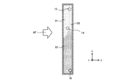
- FIG. 4 is a cross-sectional view of the gas-liquid separation chamber 20.
- FIG. 4 corresponds to the cross section of the part AA of FIG.
- the circle shown in FIG. 4 schematically represents the positions of the refrigerant inflow pipe 14, the gas flow hole 15, and the liquid flow hole 16 connected to the gas-liquid separation chamber 20.
- the gas-liquid two-phase refrigerant flows into the gas-liquid separation chamber 20 from the refrigerant inflow pipe 14.
- the liquid-phase refrigerant 92 which has a high density, is affected by gravity and accumulates unevenly in the lower part of the gas-liquid separation chamber 20.
- the gas-liquid refrigerant 91 having a low density among the gas-liquid two-phase refrigerant moves to the upper part of the gas-liquid separation chamber 20. Then, as shown in FIG. 4, the gas-phase refrigerant 91 is accumulated in the upper part, the liquid-phase refrigerant 92 is accumulated in the lower part, and the gas-liquid two-phase refrigerant is separated into the gas-phase refrigerant 91 and the liquid-phase refrigerant 92.
- the gas phase refrigerant 91 flows from the gas flow hole 15 through the gas flow pipe 15a into the bypass flow path 9 of the refrigerant circuit 99. Therefore, among the gas-liquid two-phase refrigerants that have flowed into the refrigerant distributor 10, the gas-phase refrigerant 91 flows into the bypass flow path 9.
- the liquid flow hole 16 communicating with the distribution chamber 21 is provided in the lower part of the gas-liquid separation chamber 20, the liquid phase refrigerant 92 flows into the distribution chamber 21 through the liquid flow hole 16. Therefore, the liquid phase refrigerant 92 flows into the distribution chamber 21.
- a gas-liquid two-phase refrigerant may flow to the distribution chamber 21.
- the liquid phase refrigerant 92 flows into the distribution chamber 21. Therefore, in the first embodiment, only the liquid phase refrigerant 92 flows through the plurality of heat transfer tubes 30. Therefore, in the plurality of heat transfer tubes 30, the liquid phase refrigerant 92 flows evenly in each of the heat transfer tube 30 located at the upper part and the heat transfer tube 30 located at the lower part in the direction of gravity. Therefore, when the heat exchanger 6 functions as an evaporator, the vapor phase refrigerant that does not contribute to the evaporation of the refrigerant does not flow into the heat transfer tube 30.
- FIG. 5 is a Moriel diagram of the refrigeration cycle device 100 according to the first embodiment.
- the diagram shown by the solid line is for a refrigeration cycle device as a comparative example, and is a diagram when the gas-liquid two-phase refrigerant is passed through the evaporator as it is.
- the diagram shown by the dotted line in FIG. 5 is a Moriel diagram of the refrigerant circulating in the refrigeration cycle device 100 according to the first embodiment.
- the gas-liquid two-phase refrigerant that has been decompressed by the decompression device 5 and is in the state of point D in FIGS. 1 and 5 flows into the heat exchanger 6 and separates gas and liquid. Separated in chamber 20.
- the liquid-phase refrigerant 92 separated in the gas-liquid separation chamber 20 and flowing into the distribution chamber 21 is in the state of point D2. After that, the liquid phase refrigerant 92 flows into the plurality of heat transfer tubes 30 and evaporates to the state of the point A2.
- the refrigerant that has passed through the evaporator changes from point D to point A.
- the gas-liquid two-phase refrigerant passes through the plurality of heat transfer tubes 30 and changes to the gas-phase refrigerant, but the pressure drops due to the pressure loss when passing through the plurality of heat transfer tubes 30.
- the refrigerant passing through the plurality of heat transfer tubes 30 is the liquid phase refrigerant 92 shown at point D2 in FIG.
- the vapor phase refrigerant 91 passes through the bypass flow path 9 and merges with the vapor phase refrigerant that has passed through the heat exchanger 6 which is an evaporator. That is, the vapor-phase refrigerant 91 that has passed through the bypass flow path 9 in the state of point E2 in FIG. 5 and the vapor-phase refrigerant that has passed through the plurality of heat transfer tubes 30 in the state of point E3 in FIG. 5 and evaporated.
- the refrigeration cycle device 100 separates the refrigerant into a gas phase refrigerant and a liquid phase refrigerant in the refrigerant distributor 10 of the heat exchanger 6 which is an evaporator, and a plurality of heat transfer tubes 30 of the heat exchanger 6.
- the pressure loss of the refrigerant can be reduced by allowing only the liquid-phase refrigerant to flow through the refrigerant and bypassing the vapor-phase refrigerant to the bypass flow path 9.
- Embodiment 2 In the refrigeration cycle device 200 according to the second embodiment, the bypass flow path 9 is deleted from the refrigerant circuit 99 of the refrigeration cycle device 100 according to the first embodiment, and the structure of the heat exchanger 6 is changed. In the refrigeration cycle apparatus 200 according to the second embodiment, the changes to the first embodiment will be mainly described. Regarding each part of the refrigeration cycle apparatus 200 according to the second embodiment, those having the same function in each drawing shall be labeled with the same reference numerals as those used in the description of the first embodiment.
- FIG. 6 is a refrigerant circuit diagram showing the configuration of the refrigeration cycle device 200 provided with the heat exchanger 206 according to the second embodiment.
- the refrigerant circuit 299 of the refrigeration cycle device 200 according to the second embodiment passes the refrigerant circuit 99 according to the first embodiment from the refrigerant distributor 10 of the outdoor heat exchanger 6 of the outdoor unit 1 via a plurality of heat transfer tubes 30.
- the bypass flow path 9 leading to the flow path switching device 7 has been deleted.
- FIG. 7 is an exploded perspective view illustrating the structure of the heat exchanger 206 according to the second embodiment.
- FIG. 8 is an explanatory view of a cross-sectional structure of the refrigerant distributor 210 of the heat exchanger 206 according to the second embodiment.
- the heat exchanger 206 according to the second embodiment does not have a gas flow hole 15 and a gas flow pipe 15a that go from the gas-liquid separation chamber 20 of the refrigerant distributor 210 to the outside of the heat exchanger 206. Instead, in the z direction, a gas flow hole 215 communicating with the distribution chamber 21 is provided above the gas-liquid separation chamber 20. Further, as in the first embodiment, a liquid flow hole 16 communicating with the distribution chamber 21 is provided in the lower part of the gas-liquid separation chamber 20 in the z direction.
- the distribution chamber 21 according to the second embodiment is divided into two spaces in the y direction by a dividing plate 217. That is, the distribution chamber 21 includes a first distribution chamber 221 on the windward side and a second distribution chamber 222 on the leeward side.
- the blower 6f is configured to send air in the y direction.
- the first distribution chamber 221 and the second distribution chamber 222 are partitioned by a split plate 217 formed in a comb-teeth shape according to the arrangement of the plurality of heat transfer tubes 30.
- the first distribution chamber 221 communicates with the gas-liquid separation chamber 20 by the liquid flow hole 16. Since the liquid flow hole 16 is formed in the lower part of the gas-liquid separation chamber 20 in the direction of gravity, the liquid phase refrigerant 92 accumulated in the lower part of the gas-liquid separation chamber 20 flows into the first distribution chamber 221.
- the second distribution chamber 222 communicates with the gas-liquid separation chamber 20 by the gas flow hole 215. Since the gas flow hole 215 is formed in the upper part of the gas-liquid separation chamber 20 in the direction of gravity, the gas-phase refrigerant 91 accumulated in the upper part of the gas-liquid separation chamber 20 flows into the second distribution chamber 222.
- FIG. 9 is a cross-sectional view of the gas-liquid separation chamber 20.
- FIG. 9 shows a cross section perpendicular to the x-axis, and shows a cross section of the AA portion of FIG.
- the gas-liquid two-phase refrigerant flowing in from the refrigerant inflow pipe 14 is separated under the influence of gravity as in the first embodiment.
- the gas flow hole 215 is provided in the upper part of the gas-liquid separation chamber 20, the gas phase refrigerant 91 flows into the second distribution chamber 222 of the distribution chamber 21 from the gas flow hole 215. Therefore, only the vapor phase refrigerant 91 is present in the second distribution chamber 222.
- the liquid flow hole 16 communicating with the distribution chamber 21 is provided in the lower part of the gas-liquid separation chamber 20, the liquid phase refrigerant 92 passes through the liquid flow hole 16 and is the first distribution chamber 221 of the distribution chamber 21. Flow into. Therefore, only the liquid phase refrigerant 92 is present in the first distribution chamber 221. In this way, in the heat exchanger 206 according to the second embodiment, the gas-liquid two-phase refrigerant is separated.
- the liquid flow hole 16 and the gas flow hole 215 are designed to have appropriate sizes according to the assumed refrigerant flow rate.
- FIG. 10 is a cross-sectional view of the distribution chamber 21.
- FIG. 10 shows a cross section perpendicular to the x-axis, and shows a cross section of the BB portion of FIG.
- the plurality of heat transfer tubes 30 are inserted into both the first distribution chamber 221 and the second distribution chamber 222 of the distribution chamber 21.
- the refrigerant flow section 32 (see FIG. 11) inside the plurality of heat transfer tubes 30 partially communicates with the first distribution chamber 221 and a part communicates with the second distribution chamber 222 at the end surface 33 (see FIG. 11). ..
- FIG. 11 is an explanatory diagram showing a region and a temperature distribution in which the liquid-phase refrigerant and the vapor-phase refrigerant flow in the plurality of heat transfer tubes 30 of FIG.
- the liquid phase refrigerant is flowing in the refrigerant flow section 32 in the windward region L of the plurality of heat transfer tubes 30.
- the vapor phase refrigerant is flowing in the refrigerant flow section 32 in the leeward side region G of the plurality of heat transfer tubes 30.
- it is desirable that the region L in which the liquid phase refrigerant flows into the plurality of heat transfer tubes 30 is set to be larger than the region G in which the vapor phase refrigerant flows into the plurality of heat transfer tubes 30.
- the refrigerant temperature is substantially constant in the windward region L.
- the temperature of the air that exchanges heat with the refrigerant drops due to the latent heat of the liquid refrigerant when passing through the region L.
- the refrigerant passing through the region L evaporates due to the sensible heat from the air and changes into a vapor phase refrigerant.
- the temperature of the gas phase refrigerant becomes higher as the distance from the region L through which the liquid phase refrigerant flows increases. This is because the temperature rises due to sensible heat exchange with the air passing through the region G in the portion away from the region L, and is affected by the latent heat of the liquid phase refrigerant in the region L in the region close to the region L. Is.
- the heat exchanger 206 since the liquid refrigerant flows in the region L on the wind side of the plurality of heat transfer tubes 30, it becomes easy to secure the temperature difference between the air and the refrigerant, and the heat exchanger 206 transfers heat. Thermal performance is improved.
- the heat exchanger 206 separates the gas-liquid two-phase refrigerant into the first distribution chamber 221 and the second distribution chamber 222, and then puts the liquid-phase refrigerant and the air in separate regions of the plurality of heat transfer tubes 30. It is flowing with the phase refrigerant. Therefore, in the refrigerant flowing through each of the plurality of heat transfer tubes 30, variations in the ratio of the gas phase refrigerant and the liquid phase refrigerant are suppressed. Therefore, the heat exchanger 206 can exhibit the desired heat exchange performance.
- Embodiment 3 The refrigeration cycle apparatus 300 according to the third embodiment reverses the positions of the first distribution chamber 221 and the second distribution chamber 222 of the heat exchanger 206 according to the second embodiment.
- the changes to the second embodiment will be mainly described.
- those having the same function in each drawing shall be indicated with the same reference numerals as those used in the drawings of the first and second embodiments. ..
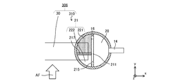
- FIG. 12 is an explanatory view of the cross-sectional structure of the refrigerant distributor 310 of the heat exchanger 306 according to the third embodiment.
- the refrigerant distributor 310 of the heat exchanger 306 the positional relationship between the first distribution chamber 221 and the second distribution chamber 222 is exchanged in the y direction. That is, in the heat exchanger 306, the second distribution chamber 222 is arranged on the leeward side, and the first distribution chamber 221 is arranged on the leeward side.
- FIG. 13 is an explanatory diagram showing a region and a temperature distribution in which the liquid-phase refrigerant and the vapor-phase refrigerant of the plurality of heat transfer tubes 30 of FIG. 12 flow.
- a region G in which the gas phase refrigerant is flowing is arranged on the windward side of the plurality of heat transfer tubes 30, and a region L in which the liquid phase refrigerant is flowing is arranged on the leeward side.
- it is desirable that the region L in which the liquid phase refrigerant flows into the plurality of heat transfer tubes 30 is set to be larger than the region G in which the vapor phase refrigerant flows into the plurality of heat transfer tubes 30.
- the refrigerant temperature in the windward region G becomes higher as the distance from the region L increases. This is because the gas phase refrigerant flowing through the region G exchanges sensible heat with the air having a high temperature passing through the region G. Therefore, since the temperature of the region G is relatively high, the occurrence of frost formation is suppressed in the windward region of the plurality of heat transfer tubes 30 where frost formation is most likely to occur when the heating operation is performed under low outside air temperature conditions. be able to. As a result, the heat exchanger 306 can exhibit the desired heat exchange performance because the air flow is not obstructed by frost formation.
- the refrigerant flowing through each of the plurality of heat transfer tubes 30 is suppressed from varying in the ratio of the gas phase refrigerant and the liquid phase refrigerant. Therefore, the heat exchanger 306 can exhibit the desired heat exchange performance.
- Embodiment 4 The refrigeration cycle apparatus 400 according to the fourth embodiment is a modification of the structure of the heat exchanger 206 according to the second embodiment.
- the changes to the second embodiment will be mainly described.
- those having the same function in each drawing shall be indicated with the same reference numerals as those used in the drawings of the first to third embodiments. ..
- FIG. 14 is an exploded perspective view illustrating the structure of the heat exchanger 406 according to the fourth embodiment.
- FIG. 15 is an explanatory view of a cross-sectional structure of the refrigerant distributor 410 of the heat exchanger 406 according to the fourth embodiment.
- the refrigerant distributor 410 of the heat exchanger 406 according to the fourth embodiment separates the gas-liquid two-phase refrigerant flowing from the refrigerant inflow pipe 14 into the gas-phase refrigerant and the liquid-phase refrigerant in the gas-liquid separation chamber 20. It is the same as the heat exchangers 6, 206 and 306 in the first to third forms of the above.
- the distribution chamber 421 to which the plurality of heat transfer tubes 30 are connected is divided into a plurality of parts by the partition member 42 in the z direction. Further, a liquid chamber 427 in which only the liquid phase refrigerant flows and a gas chamber 428 in which only the gas phase refrigerant flows are provided between the gas-liquid separation chamber 20 and the distribution chamber 421.
- a gas flow hole 415a is provided in the upper part of the gas-liquid separation chamber 20, that is, the upper part of the partition plate 411, and a liquid flow hole 416a is provided in the lower part. Since the gas chamber 428 communicates with the gas-liquid separation chamber 20 through the gas flow hole 415a, only the gas-phase refrigerant flows in. Further, since the liquid chamber 427 communicates with the gas-liquid separation chamber 20 through the liquid flow hole 416a, only the liquid phase refrigerant flows in. The liquid chamber 427 and the gas chamber 428 are separated by a dividing plate 417, and each is an independent space. Further, the liquid chamber 427, the gas chamber 428, and the distribution chamber 421 are separated by a partition plate 418.
- the liquid chamber 427 is provided in the partition plate 418, and the liquid chamber 427 is provided with a liquid flow hole 416b that communicates with the distribution chamber 421. Further, the gas chamber 428 includes a gas flow hole 415b communicating with the distribution chamber 421.
- the distribution chamber 421 into which the plurality of heat transfer tubes 30 are inserted is divided into a plurality of confluence portions 421a, 421b, 421c and 421d in the z direction.
- the liquid flow hole 416b and the gas flow hole 415b are provided corresponding to a plurality of confluence portions 421a, 421b, 421c and 421d, respectively.
- the liquid phase refrigerant in the liquid chamber 427 and the gas phase refrigerant in the gas chamber 428 flow into the plurality of confluence portions 421a, 421b, 421c and 421d without any bias.
- the gas-phase refrigerant and the liquid-phase refrigerant that have flowed into the plurality of merging portions 421a, 421b, 421c, and 421d are mixed and flow into the plurality of heat transfer tubes 30.
- the separated vapor phase refrigerant and liquid phase refrigerant flow in from different paths, so that the variation in the ratio of the vapor phase refrigerant and the liquid phase refrigerant can be suppressed.
- the plurality of heat transfer tubes 30 are flat multi-hole tubes, if the vapor phase refrigerant and the liquid phase refrigerant flow individually in each refrigerant flow path, a temperature difference occurs between the vapor phase refrigerant and the liquid phase refrigerant. Then, heat exchange occurs between the gas phase refrigerant and the liquid phase refrigerant, and the amount of heat exchange between the air passing through the heat exchanger and the refrigerant may decrease.
- the gas phase refrigerant and the liquid phase refrigerant flow into and merge with the plurality of merging portions 421a, 421b, 421c and 421d at similar ratios, respectively.
- a refrigerant in which a gas phase refrigerant and a liquid phase refrigerant are mixed can flow through each of the plurality of heat transfer tubes 30, so that heat exchange between the gas phase refrigerant and the liquid phase refrigerant can be suppressed, and the air and the refrigerant can be used. Heat exchange is promoted.
- the gas-liquid two-phase refrigerant is once separated into the gas-phase refrigerant and the liquid-phase refrigerant, and then the plurality of confluence portions 421a, 421b, and 421c are divided. And 421d to join.
- FIG. 16 is an exploded perspective view illustrating the structure of the heat exchanger 406a, which is a modification of the heat exchanger 406 according to the fourth embodiment.
- the heat exchanger 406 creates a space for separating and merging the refrigerant by partitioning the refrigerant distributor 410 into three spaces in the x direction using two partition plates 411 and 418.
- the plate materials 451 and 454 are laminated and provided with holes or elongated holes such as gas flow holes 415 and liquid flow holes 416, respectively, to provide a space for separating the refrigerant. It creates a space where they meet.
- the liquid chamber 427 and the gas chamber 428 are formed by providing two elongated holes 452 whose major axes extend in the z direction in parallel in the y direction on one plate member 451. Then, the central portion 453 of the plate material 451 between the two elongated holes 452 becomes a portion corresponding to the divided plate 417.
- One of the two elongated holes 452 communicates with the gas-liquid separation chamber 20 through the gas flow hole 415, and the other communicates with the gas-liquid separation chamber 20 through the liquid flow hole 416.
- the plurality of distribution chambers 421 of the heat exchanger 406a according to the modified example are formed by providing a plurality of elongated holes 455 having a long axis extending in the y direction in parallel in the z direction in the plate material 454.
- the plurality of elongated holes 455 are formed corresponding to each of the plurality of heat transfer tubes 30.
- Each of the plurality of elongated holes 455 communicates with both the elongated hole 452 which is the liquid chamber 427 and the elongated hole 452 which is the gas chamber 428.
- the plurality of elongated holes 455 correspond to each of the plurality of heat transfer tubes 30, but the present invention is not limited to this form.
- one distribution chamber 421 may be connected corresponding to two or more heat transfer tubes 30.
- the refrigerant distributor 410a of the heat exchanger 406a according to the modified example is formed by laminating members having a simple shape such as plate members 451 and 454 that only provide holes. Therefore, the heat exchanger 406a can be manufactured at low cost with a small number of parts. Further, in the refrigerant distributor 410a of the heat exchanger 406a, since members such as plate members 451 and 454 are laminated, the thickness dimension in the x direction is reduced, so that a plurality of heat transfer tubes 30 are installed accordingly. The area of the heat transfer part can be increased.
- Embodiment 5 The refrigeration cycle apparatus 500 according to the fifth embodiment is a modification of the structure of the heat exchanger 206 according to the second embodiment. In the refrigeration cycle apparatus 500 according to the fifth embodiment, the changes to the second embodiment will be mainly described. Regarding each part of the refrigeration cycle apparatus 500 according to the fifth embodiment, those having the same function in each drawing shall be indicated with the same reference numerals as those used in the drawings of the first to fourth embodiments. ..
- FIG. 17 is an explanatory view of the cross-sectional structure of the heat exchanger 506 according to the fifth embodiment.
- FIG. 17 shows a cross section along the xz axis.
- the refrigerant distributor 510 of the heat exchanger 506 according to the fifth embodiment includes a liquid-refrigerant trapping structure 570 in the gas-liquid separation chamber 20.
- the liquid refrigerant trapping structure 570 is, for example, a mesh filter, and the fineness and material of the mesh can be appropriately set.
- the liquid refrigerant trapping structure 570 is located between the refrigerant inflow pipe 514 and the gas flow hole 15 in the z direction, and is arranged so as to partition the gas-liquid separation chamber 20 in the z direction.
- the refrigerant inflow pipe 514 is inclined in the z opposite direction and inserted into the gas-liquid separation chamber 20. Therefore, the gas-liquid two-phase refrigerant flowing in from the refrigerant inflow pipe 514 proceeds in the z opposite direction. In the process, the gas-liquid two-phase refrigerant is affected by gravity, and the liquid-phase refrigerant is unevenly accumulated in the lower part of the gas-liquid separation chamber 20. Further, the gas-phase refrigerant and the liquid-phase refrigerant having fine particles are unevenly distributed in the upper part of the gas-liquid separation chamber 20.
- a gas flow hole 15 is installed in the upper part of the gas-liquid separation chamber 20, and the separated gas-phase refrigerant flows into the second distribution chamber 222 of the distribution chamber 21. At this time, the liquid-phase refrigerant floating as fine particles together with the gas-phase refrigerant may also flow into the second distribution chamber 222.
- the refrigerant distributor 510 of the heat exchanger 506 according to the fifth embodiment is from the first distribution chamber 221 and the second distribution chamber 222, similarly to the refrigerant distributor 210 of the heat exchanger 206 according to the second embodiment.
- the distribution chamber 21 is provided.
- the liquid refrigerant trapping structure 570 has a structure that allows the vapor phase refrigerant to pass through. Since the heat exchanger 506 is provided with the liquid refrigerant trapping structure 570, the liquid refrigerant moving to the upper part of the gas-liquid separation chamber 20 together with the gas phase refrigerant adheres to the liquid refrigerant trapping structure 570 and becomes droplets in the direction of gravity. Fall into. As a result, in the heat exchanger 506 according to the fifth embodiment, the separation of the gas phase refrigerant and the liquid phase refrigerant is promoted.
- Embodiment 6 The refrigeration cycle apparatus 600 according to the sixth embodiment is a modification of the structure of the heat exchanger 206 according to the second embodiment.
- the changes to the second embodiment will be mainly described.
- those having the same function in each drawing shall be indicated with the same reference numerals as those used in the drawings of the first to fifth embodiments. ..
- FIG. 18 is an explanatory view of the cross-sectional structure of the heat exchanger 606 according to the sixth embodiment.
- FIG. 18 shows a cross section along the xz axis.
- the refrigerant distributor 610 of the heat exchanger 606 according to the sixth embodiment includes a baffle plate 670 in the gas-liquid separation chamber 20.
- the baffle plate 670 is arranged below the portion where the refrigerant inflow pipe 614 is inserted, and extends from the wall surface on which the refrigerant inflow pipe 614 is installed toward the partition plate 11.
- the baffle plate 670 is formed with a communication hole 671 that communicates the upper part and the lower part of the gas-liquid separation chamber 20 at a portion on the partition plate 11 side.
- the baffle plate 670 is inclined in the z-reverse direction toward the partition plate 11, so that the gas-liquid two-phase refrigerant flowing from the refrigerant inflow pipe 614, which is also inclined in the z-reverse direction, flows along the baffle plate 670. It is formed.
- the baffle plate 670 and the refrigerant inflow pipe 614 are formed so as to be parallel to each other, but the present invention is not limited to this.
- the refrigerant inflow pipe 614 may be tilted in the z-opposite direction larger than the baffle plate 670 so that the gas-liquid two-phase refrigerant flowing in from the refrigerant inflow pipe 614 hits the baffle plate 670.
- the liquid-phase refrigerant contained in the gas-liquid two-phase refrigerant adheres to the surface of the baffle plate 670 and flows downward from the communication hole 671. As a result, gas-liquid separation of the refrigerant is promoted in the gas-liquid separation chamber 20.
- the gas-liquid separation chamber 20 is divided into two spaces in the z direction by a baffle plate 670.
- the space below the baffle plate 670 is referred to as a first space 620a
- the space above the baffle plate 670 is referred to as a second space 620b.
- a gas flow pipe 615a is connected to a gas flow hole 615 provided in the second space 620b, which is the space above the gas-liquid separation chamber 20.
- the tip portion 615b of the gas flow pipe 615a is located in the second space 620b, which is the space below the baffle plate 670.
- the gas flow pipe 615a is configured to send the gas phase refrigerant from the upper part of the space below the baffle plate 670 to the second distribution chamber 222.
- the liquid-phase refrigerant adheres to the obstruction plate 670 and the partition plate 11 and flows downward, so that the gas-phase refrigerant flows into the gas flow pipe 615a. Therefore, the gas-liquid separation of the refrigerant in the gas-liquid separation chamber 20 is efficiently performed.
- the heat exchangers 6, 206, 306, 406, 506, and 606 according to the first to sixth embodiments may be configured by laminating plate materials in a part of the structure like the heat exchanger 406a.
- the heat exchangers 6, 206, 306, 406, 506 and 606 may be applied not only to the outdoor unit 1 but also to the indoor unit 2.
- the present disclosure may be configured by combining each embodiment.
- the liquid refrigerant trapping structure 570 of the fifth embodiment may be applied to the first, third, fourth, or sixth embodiments.
- the structure of the baffle plate 670 of the sixth embodiment may be applied to the first, third, fourth, or fifth embodiments.
Landscapes
- Engineering & Computer Science (AREA)
- Physics & Mathematics (AREA)
- Thermal Sciences (AREA)
- Mechanical Engineering (AREA)
- General Engineering & Computer Science (AREA)
- Heat-Exchange Devices With Radiators And Conduit Assemblies (AREA)
- Details Of Heat-Exchange And Heat-Transfer (AREA)
Priority Applications (3)
| Application Number | Priority Date | Filing Date | Title |
|---|---|---|---|
| PCT/JP2020/013890 WO2021192192A1 (ja) | 2020-03-27 | 2020-03-27 | 熱交換器、熱交換器ユニット及び冷凍サイクル装置 |
| JP2022510301A JP7493585B2 (ja) | 2020-03-27 | 2020-03-27 | 熱交換器、熱交換器ユニット及び冷凍サイクル装置 |
| EP20927408.3A EP4130612A4 (en) | 2020-03-27 | 2020-03-27 | HEAT EXCHANGER, HEAT EXCHANGER UNIT AND REFRIGERATION CYCLE DEVICE |
Applications Claiming Priority (1)
| Application Number | Priority Date | Filing Date | Title |
|---|---|---|---|
| PCT/JP2020/013890 WO2021192192A1 (ja) | 2020-03-27 | 2020-03-27 | 熱交換器、熱交換器ユニット及び冷凍サイクル装置 |
Publications (1)
| Publication Number | Publication Date |
|---|---|
| WO2021192192A1 true WO2021192192A1 (ja) | 2021-09-30 |
Family
ID=77891115
Family Applications (1)
| Application Number | Title | Priority Date | Filing Date |
|---|---|---|---|
| PCT/JP2020/013890 Ceased WO2021192192A1 (ja) | 2020-03-27 | 2020-03-27 | 熱交換器、熱交換器ユニット及び冷凍サイクル装置 |
Country Status (3)
| Country | Link |
|---|---|
| EP (1) | EP4130612A4 (https=) |
| JP (1) | JP7493585B2 (https=) |
| WO (1) | WO2021192192A1 (https=) |
Cited By (1)
| Publication number | Priority date | Publication date | Assignee | Title |
|---|---|---|---|---|
| CN118548613A (zh) * | 2024-05-30 | 2024-08-27 | 山东钰霖制冷设备有限公司 | 一种制冷设备用换热器装置 |
Citations (4)
| Publication number | Priority date | Publication date | Assignee | Title |
|---|---|---|---|---|
| JP2017155992A (ja) * | 2016-02-29 | 2017-09-07 | 三菱重工業株式会社 | 熱交換器及び空気調和機 |
| WO2018002983A1 (ja) * | 2016-06-27 | 2018-01-04 | 三菱電機株式会社 | 冷凍サイクル装置 |
| WO2018116929A1 (ja) * | 2016-12-20 | 2018-06-28 | 三菱重工サーマルシステムズ株式会社 | 熱交換器及び空気調和機 |
| JP6369650B1 (ja) | 2017-03-27 | 2018-08-08 | ダイキン工業株式会社 | 熱交換器および空気調和装置 |
Family Cites Families (5)
| Publication number | Priority date | Publication date | Assignee | Title |
|---|---|---|---|---|
| JPH06341736A (ja) * | 1993-06-01 | 1994-12-13 | Nippondenso Co Ltd | 冷媒凝縮器 |
| JP3122578B2 (ja) * | 1994-06-23 | 2001-01-09 | シャープ株式会社 | 熱交換器 |
| WO2008064219A1 (en) * | 2006-11-22 | 2008-05-29 | Johnson Controls Technology Company | Multichannel evaporator with flow mixing manifold |
| JP2011094946A (ja) * | 2009-09-30 | 2011-05-12 | Daikin Industries Ltd | ガス冷媒分離器、ガス冷媒分離兼冷媒分流器、膨張弁及び冷凍装置 |
| DE102012019512A1 (de) * | 2012-10-05 | 2014-04-10 | Hochschule Coburg -Hochschule für angewandte Wissenschaften- | Kältemittelkreislauf sowie Trennvorrichtung und Verdampfer für einen Kältemittelkreislauf |
-
2020
- 2020-03-27 JP JP2022510301A patent/JP7493585B2/ja active Active
- 2020-03-27 WO PCT/JP2020/013890 patent/WO2021192192A1/ja not_active Ceased
- 2020-03-27 EP EP20927408.3A patent/EP4130612A4/en not_active Withdrawn
Patent Citations (4)
| Publication number | Priority date | Publication date | Assignee | Title |
|---|---|---|---|---|
| JP2017155992A (ja) * | 2016-02-29 | 2017-09-07 | 三菱重工業株式会社 | 熱交換器及び空気調和機 |
| WO2018002983A1 (ja) * | 2016-06-27 | 2018-01-04 | 三菱電機株式会社 | 冷凍サイクル装置 |
| WO2018116929A1 (ja) * | 2016-12-20 | 2018-06-28 | 三菱重工サーマルシステムズ株式会社 | 熱交換器及び空気調和機 |
| JP6369650B1 (ja) | 2017-03-27 | 2018-08-08 | ダイキン工業株式会社 | 熱交換器および空気調和装置 |
Non-Patent Citations (1)
| Title |
|---|
| See also references of EP4130612A4 |
Cited By (2)
| Publication number | Priority date | Publication date | Assignee | Title |
|---|---|---|---|---|
| CN118548613A (zh) * | 2024-05-30 | 2024-08-27 | 山东钰霖制冷设备有限公司 | 一种制冷设备用换热器装置 |
| CN118548613B (zh) * | 2024-05-30 | 2024-12-27 | 安徽笃舜智能装备有限公司 | 一种制冷设备用换热器装置 |
Also Published As
| Publication number | Publication date |
|---|---|
| EP4130612A1 (en) | 2023-02-08 |
| EP4130612A4 (en) | 2023-04-26 |
| JP7493585B2 (ja) | 2024-05-31 |
| JPWO2021192192A1 (https=) | 2021-09-30 |
Similar Documents
| Publication | Publication Date | Title |
|---|---|---|
| JP6352401B2 (ja) | 空気調和装置 | |
| EP3767218B1 (en) | Heat exchanger and air-conditioning device | |
| JP4887213B2 (ja) | 冷媒分配器及び空気調和機 | |
| TWI768340B (zh) | 熱交換器及冷凍循環裝置 | |
| KR101647908B1 (ko) | 공기 조화 장치 | |
| EP3580516A1 (en) | Condenser with tube support structure | |
| KR102148724B1 (ko) | 열교환기 및 이를 갖는 공기조화기 | |
| JP2018162900A (ja) | 熱交換器、および、それを備えた空気調和機 | |
| US7163052B2 (en) | Parallel flow evaporator with non-uniform characteristics | |
| JP6890509B2 (ja) | 空気調和機 | |
| JP7086279B2 (ja) | 冷媒分配器、熱交換器及び冷凍サイクル装置 | |
| JP6987227B2 (ja) | 熱交換器及び冷凍サイクル装置 | |
| JP2018194251A (ja) | 熱交換器 | |
| JP6793831B2 (ja) | 熱交換器、及び冷凍サイクル装置 | |
| WO2021192192A1 (ja) | 熱交換器、熱交換器ユニット及び冷凍サイクル装置 | |
| WO2021074950A1 (ja) | 熱交換器及び熱交換器を搭載した空気調和装置 | |
| JP2020085267A (ja) | 熱交換器 | |
| CN113739454A (zh) | 热交换器 | |
| KR101822898B1 (ko) | 하이브리드모듈 및 이를 이용한 공기조화기 | |
| JP7642170B1 (ja) | 熱交換器、熱交換器を備えた室外機、および、室外機を備えた空気調和装置 | |
| JP7146077B2 (ja) | 熱交換器及び空気調和装置 | |
| WO2025169459A1 (ja) | 熱交換器及び空気調和装置 | |
| WO2025253428A1 (ja) | 熱交換器、冷凍サイクル装置の室外機、および冷凍サイクル装置 | |
| WO2022038717A1 (ja) | 熱交換器 | |
| WO2023199466A1 (ja) | 熱交換器及びこれを有する空気調和装置 |
Legal Events
| Date | Code | Title | Description |
|---|---|---|---|
| 121 | Ep: the epo has been informed by wipo that ep was designated in this application |
Ref document number: 20927408 Country of ref document: EP Kind code of ref document: A1 |
|
| ENP | Entry into the national phase |
Ref document number: 2022510301 Country of ref document: JP Kind code of ref document: A |
|
| WWE | Wipo information: entry into national phase |
Ref document number: 2020927408 Country of ref document: EP |
|
| ENP | Entry into the national phase |
Ref document number: 2020927408 Country of ref document: EP Effective date: 20221027 |
|
| NENP | Non-entry into the national phase |
Ref country code: DE |