WO2021187610A1 - 培養操作装置 - Google Patents
培養操作装置 Download PDFInfo
- Publication number
- WO2021187610A1 WO2021187610A1 PCT/JP2021/011263 JP2021011263W WO2021187610A1 WO 2021187610 A1 WO2021187610 A1 WO 2021187610A1 JP 2021011263 W JP2021011263 W JP 2021011263W WO 2021187610 A1 WO2021187610 A1 WO 2021187610A1
- Authority
- WO
- WIPO (PCT)
- Prior art keywords
- pipette
- container body
- cap
- capper
- work
- Prior art date
- Legal status (The legal status is an assumption and is not a legal conclusion. Google has not performed a legal analysis and makes no representation as to the accuracy of the status listed.)
- Ceased
Links
Images


Classifications
-
- C—CHEMISTRY; METALLURGY
- C12—BIOCHEMISTRY; BEER; SPIRITS; WINE; VINEGAR; MICROBIOLOGY; ENZYMOLOGY; MUTATION OR GENETIC ENGINEERING
- C12M—APPARATUS FOR ENZYMOLOGY OR MICROBIOLOGY; APPARATUS FOR CULTURING MICROORGANISMS FOR PRODUCING BIOMASS, FOR GROWING CELLS OR FOR OBTAINING FERMENTATION OR METABOLIC PRODUCTS, i.e. BIOREACTORS OR FERMENTERS
- C12M41/00—Means for regulation, monitoring, measurement or control, e.g. flow regulation
- C12M41/48—Automatic or computerized control
-
- C—CHEMISTRY; METALLURGY
- C12—BIOCHEMISTRY; BEER; SPIRITS; WINE; VINEGAR; MICROBIOLOGY; ENZYMOLOGY; MUTATION OR GENETIC ENGINEERING
- C12M—APPARATUS FOR ENZYMOLOGY OR MICROBIOLOGY; APPARATUS FOR CULTURING MICROORGANISMS FOR PRODUCING BIOMASS, FOR GROWING CELLS OR FOR OBTAINING FERMENTATION OR METABOLIC PRODUCTS, i.e. BIOREACTORS OR FERMENTERS
- C12M1/00—Apparatus for enzymology or microbiology
-
- C—CHEMISTRY; METALLURGY
- C12—BIOCHEMISTRY; BEER; SPIRITS; WINE; VINEGAR; MICROBIOLOGY; ENZYMOLOGY; MUTATION OR GENETIC ENGINEERING
- C12M—APPARATUS FOR ENZYMOLOGY OR MICROBIOLOGY; APPARATUS FOR CULTURING MICROORGANISMS FOR PRODUCING BIOMASS, FOR GROWING CELLS OR FOR OBTAINING FERMENTATION OR METABOLIC PRODUCTS, i.e. BIOREACTORS OR FERMENTERS
- C12M1/00—Apparatus for enzymology or microbiology
- C12M1/36—Apparatus for enzymology or microbiology including condition or time responsive control, e.g. automatically controlled fermentors
-
- C—CHEMISTRY; METALLURGY
- C12—BIOCHEMISTRY; BEER; SPIRITS; WINE; VINEGAR; MICROBIOLOGY; ENZYMOLOGY; MUTATION OR GENETIC ENGINEERING
- C12M—APPARATUS FOR ENZYMOLOGY OR MICROBIOLOGY; APPARATUS FOR CULTURING MICROORGANISMS FOR PRODUCING BIOMASS, FOR GROWING CELLS OR FOR OBTAINING FERMENTATION OR METABOLIC PRODUCTS, i.e. BIOREACTORS OR FERMENTERS
- C12M23/00—Constructional details, e.g. recesses, hinges
- C12M23/40—Manifolds; Distribution pieces
-
- C—CHEMISTRY; METALLURGY
- C12—BIOCHEMISTRY; BEER; SPIRITS; WINE; VINEGAR; MICROBIOLOGY; ENZYMOLOGY; MUTATION OR GENETIC ENGINEERING
- C12M—APPARATUS FOR ENZYMOLOGY OR MICROBIOLOGY; APPARATUS FOR CULTURING MICROORGANISMS FOR PRODUCING BIOMASS, FOR GROWING CELLS OR FOR OBTAINING FERMENTATION OR METABOLIC PRODUCTS, i.e. BIOREACTORS OR FERMENTERS
- C12M3/00—Tissue, human, animal or plant cell, or virus culture apparatus
Definitions
- the present invention relates to the field of cell culture, specifically, a culture manipulation device.
- An object of the present invention in the field of cell culture is to provide a culture operation device capable of preventing mistakes from occurring during work by automating the work from manual work by humans to using a robot.
- the present invention comprises a plurality of containers having a container body and a cap that engages with the container body. With multiple pipette tips, By manipulating the container body and cap of the container, the mounting member on which the plurality of pipette tips are placed, and the caps of different containers, the cap and the corresponding container body can be engaged and separated.
- the realized capper, the pipette member that selectively attaches and detaches different pipette tips, and the pipette work of the container body is performed by the attached pipette tip, and the capper and the pipette member are attached to the above-mentioned placing member.
- a stage provided with a moving member that is relatively displaced in three directions, a vertical direction orthogonal to each other, a first horizontal direction, and a second horizontal direction.
- a control unit that controls the engaging and disengaging work of the capper, the selective attachment and detachment of the pipette tips of different pipette members, the pipette work, and the realization of relative displacement of the moving member according to a predetermined program.
- a safety cabinet in which the above-mentioned placing member, the capper, the pipette member, and the moving member are all placed in the working environment by providing a sterile working environment and the stage is arranged inside.
- a culture operation device is provided.
- the previously described placing member is A container body accommodating portion for accommodating the container body of the corresponding container, and a container body accommodating portion.
- a pipette tip accommodating portion for accommodating the pipette tip before use, A pipette tip collecting unit for collecting the used pipette tip is provided.
- the container body accommodating portion is A fixed accommodating portion that holds the corresponding container body at a predetermined angle with respect to the stage.
- a movable accommodating portion that rotatably holds the corresponding container body with respect to the stage is provided.
- the movable accommodating portion rotates its corresponding container body in the first horizontal direction and / or in the second horizontal direction.
- "and / or” means at least one of both, and either one and both are included.
- the container body accommodating portion is provided with a sandwiching module for sandwiching the container body of the container, and the sandwiching module has a plurality of sandwiching portions that approach or separate from each other in a predetermined direction.
- the container main body of the container is fixedly held with respect to the container main body accommodating portion via the plurality of holding portions.
- the cap mounting portion is formed with a storage portion that aligns with the shape of each cap and accommodates the cap.
- the capper includes a torque detecting member that detects a resistance received during an engaging or disengaging operation, and when the torque detected by the torque detecting member is higher than a predetermined value, the control unit performs the above. It is controlled to stop the operation of the capper with respect to the cap.
- the pipette member is An insertion part that performs pipette work through the joined pipette tip by inserting and joining into the pipette tip. It is provided with a unloading portion for releasing the joint of the pipette tip from the insertion portion by moving with respect to the insertion portion.
- the pipette member further comprises a microquantity pipette unit for collecting a quantitative solution from the container or injecting the quantitative solution into the container.
- the present invention also includes a plurality of containers having caps that engage with the container body.
- a pipette member capable of selectively attaching and detaching the pipette tip from the plurality of pipette tips and inserting the attached pipette tip into the container body to perform pipette work.
- a moving member that displaces the capper and the pipette member relative to the previously described placing member.
- a culture operation including the engaging work and the separating work by the capper, the selective attachment and detachment of the pipette tip by the pipette member, the pipette work, and a control unit for controlling the relative movement of the moving member.
- a culture operation including the engaging work and the separating work by the capper, the selective attachment and detachment of the pipette tip by the pipette member, the pipette work, and a control unit for controlling the relative movement of the moving member.
- a stage provided with the above-mentioned placing member, the capper, and the moving member, and the like.
- a sterile working environment is formed inside, and a safety cabinet in which the stage is arranged inside is provided inside.
- the present invention provides the following culture operation device.
- the culture operation device includes a stage and a control unit.
- the stage is in a sterile working environment in a safety cabinet.
- the capper and the pipette member that selectively attaches and detaches different pipette tips and pipettes the container body with the attached pipette tip, and the capper and the pipette member are at least three orthogonal to each other with respect to the mounting member.
- a moving member that is relatively displaced in the direction is provided.
- control unit can accurately control and move the capper engaging and disassembling operations, the selective attachment and detachment of pipette tips of different pipette members, and the pipette operation with an accurate amount according to a predetermined program. Since the relative displacement of the members can be accurately controlled, it is possible to prevent mistakes from occurring during the work by automating the work in the cell culture field from manual work by humans to using a robot.
- FIG. 1 is a front schematic view showing a culture operation device according to one embodiment of the present invention.
- the safety cabinet is omitted.
- FIG. 2 is a schematic plan view showing a culture operation device according to an embodiment of the present invention.
- the safety cabinet is omitted.
- FIG. 3 shows a part of the structure of FIG.
- the part of the structure is a structure housed in a safety cabinet.
- FIG. 4 shows a part of the structure of FIG.
- the part of the structure is a structure housed in a safety cabinet.
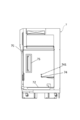
- FIG. 5 is a front schematic view showing a safety cabinet of the culture operation device according to one embodiment of the present invention. Of these, FIG. 5 is a schematic view showing the exterior of the safety cabinet.
- FIG. 6 is a side schematic view showing a safety cabinet of the culture operation device according to one embodiment of the present invention. The schematic side view shown in FIG. 6 shows the interior portion of the safety cabinet.
- the "vertical direction” refers to the direction of gravity of the earth (vertical direction in FIG. 1)
- the "first horizontal direction” and the “second horizontal direction” are planes orthogonal to the vertical direction. Refers to two directions orthogonal to each other within (the first horizontal direction is the left-right direction in FIG. 1 and the up-down direction in FIG. 2, and the second horizontal direction is the left-right direction in FIG. 2).
- the culture operation device is provided inside the safety cabinet 7, the control unit 1 provided outside the safety cabinet 7, and the inside of the safety cabinet 7. It includes a plurality of containers C, a plurality of pipette tips T, a stage 2, a mounting member 3, a capper 4, a pipette member 5, and a moving member 6.
- the container C is a container for storing a medium for cell culture, a cell solution, and the like.
- each of the containers C has a container body CB forming a storage space and a cap CL for closing the opening of the container body CB (FIG. 1). 4).
- the container C is divided into a first bottle C1, a second bottle C2, and a third bottle C3.
- the first bottle C1 is a bottle having a circular cross section of the container body CB (in this embodiment, there are five). All the first bottles C1 are housed in the fixed storage part 311.
- the second bottle C2 is a bottle having a rectangular cross section of the container body CB (in the present embodiment, there is one).
- the second bottle C2 is housed in the movable storage unit 312 and may be a multi-layer cell culture bottle.
- the interior of the second bottle C2 may have a funnel structure or other structure that favors the concentration, flow and distribution of the medium and cell solutions.
- the third bottle C3 is a bottle having a regular octagonal cross section of the container body CB (in the present embodiment, there are two).
- One third bottle C3 is housed in the fixed storage section 311 and the other third bottle C3 is housed in the movable storage section 312.
- the plurality of pipette tips T cooperate with the pipette member 5 to quantitatively collect the medium and the cell solution from different containers C, and inject the collected medium and the cell solution into the other container C. Achieves quantitative pipette work.
- Each pipette tip T has an opening that matches the insertion portion 51 of the pipette member 5, and the lower end portion of each pipette tip T has a tapered shape toward the lower end.
- the stage 2 is installed on the work table 72 in the safety cabinet 7 (see FIGS. 1, 2 and 6).
- the stage 2 has a work surface 2a extending along the horizontal direction.
- a mounting member 3, a capper 4, a pipette member 5, and a moving member 6 are installed on the work surface 2a.
- the mounting member 3 is provided for mounting the container body CB, the cap CL, and the plurality of pipette tips T of the container C, respectively.
- the mounting member 3 includes the container body accommodating portion 31, the cap embedding portion 32, the pipette tip accommodating portion 33, and the pipette. It has a chip collecting unit 34.
- the container body accommodating portion 31 accommodates the container body CB of the corresponding container C and has an accommodating space that matches the cross-sectional shape of the container body CB.
- the container body accommodating portion 31 has a fixed accommodating portion 311 that cannot rotate with respect to the work surface 2a and a movable accommodating portion 312 that is rotatable with respect to the work surface 2a.
- the fixed storage unit 311 holds the corresponding container body CB at a predetermined angle with respect to the work surface 2a.
- the fixed storage unit 311 holds the corresponding container body CB so that its central axis is orthogonal to the work surface 2a. That is, the central axis of the container body CB is along the vertical direction V. This orthogonality is an example of a "predetermined angle".
- the pipette member 5 uses the pipette tip T to use the pipette tip T to view the container body CB from above the container body CB. It is possible to enter inside and perform sampling work and injection work.
- each fixed storage unit 311 is provided with a holding module for holding the container body CB of the container C. Since the sandwiching module has two sandwiching portions 313 that approach or separate from each other in the first horizontal direction H1, the container body CB of the container C is fixedly held by the two sandwiching portions 313, and the container body CB is accommodated in the container body CB. It can be fixed to the portion 31. In this way, in the process of operating the cap CL of the container C by the capper 4 to engage or separate the cap CL from the container body CB, the container body CB does not become rotatable with the operation of the capper 4.
- the movable storage unit 312 rotatably holds the corresponding container body CB with respect to the work surface 2a.
- the central axis of the second bottle C2 is the first horizontal direction H1. It is possible to have a predetermined angle around the work surface 2a. Since the movable accommodating portion 312 for accommodating the one third bottle C3 is rotatable around the first horizontal direction H1 and the second horizontal direction H2, the central axis of the third bottle C3 is the third. It is possible to have a predetermined angle with respect to the work surface 2a around the horizontal direction H1 of 1 and the second horizontal direction H2.
- the central axes of the second bottle C2 and the third bottle C3 may be arranged parallel to the horizontal plane, and the second bottle C2 and the third bottle C3 can rotate around their respective axes. It may be arranged. As described above, it is advantageous to inject the medium and the cell solution into the second bottle C2 and the third bottle C3, and it is also advantageous to uniformly mix and distribute the medium and the cell solution.
- the cap mounting portion 32 is provided for mounting the cap CL removed from the container C.
- the cap mounting portion 32 is formed with a recess 321 (storage portion) that matches the shape of each cap CL, so that the recess 321 can accommodate the corresponding cap CL.
- the distribution of the recesses 321 formed in the cap mounting portion 32 matches the distribution of the container body accommodating portion 31 so that the system can easily identify the removed cap CL and its corresponding recesses 321. That is, in the present embodiment, the positions of the recess 321 of the cap mounting portion 32 and the cap CL of the container C accommodating portion correspond to each other, and in the second horizontal direction H2 of each recess 321 and the corresponding cap CL.
- the corresponding cap CL is placed in the corresponding recess 321 by being equal to the distance of.
- a positioning convex portion protruding outward in the radial direction is formed on the outer peripheral wall of at least a part of the cap CLs of the plurality of containers C, and positioning is performed on the inner peripheral wall of the concave portion 321 that matches the cap CL.
- a positioning recess (not shown) that matches the protrusion is formed.
- the pipette tip accommodating portion 33 is provided to accommodate the pipette tip T before use.
- the pipette tip T before use has one region because there are eight pipette tip accommodating portions 33 and they are arranged in an array in the first horizontal direction H1 and the second horizontal direction H2. It is compactly located inside and easy to manage.
- the pipette tip collecting unit 34 is provided to collect the used pipette tip T.
- similarly to the pipette tip accommodating portion 33 there are eight pipette tip collecting portions 34, and the pipette tip collecting portions 34 are arranged in an array in the first horizontal direction H1 and the second horizontal direction H2.
- the used pipette tip T is compactly located in one area and is easy to manage.
- the capper 4 is provided to realize the engaging work and the separating work of the cap CL and the corresponding container body CB by operating the cap CLs of different containers C.
- the capper 4 has an engaging claw 41 that can be engaged with the cap CL of the container C and can rotate in two directions around the vertical direction V.
- the engaging claw 41 has three claw portions 411 that are uniformly distributed in the circumferential direction of the cap CL, so that the cap CL of the container C can be tightened or loosened.
- the engaging claw 41 engages with the cap CL attached to the container body CB of the container C from the outside, and then rotates in one direction to remove the cap CL from the container body CB, and the cap CL and the container body CB Can be separated.
- the engaging claw 41 can close the opening of the container body CB by engaging the cap CL and the container body CB.
- the capper 4 further includes a rotation module 42 that rotates the engaging claw 41 in two directions.
- the rotary module 42 can determine whether or not the cap CL is securely engaged with the container body CB according to the magnitude of the torque.
- the capper 4 further includes a torque detecting member capable of detecting the torque (resistance) received when the engaging claw 41 rotates around the vertical direction V.
- the control unit 1 controls the engaging claw 41 so as to be separated from the cap CL. That is, the control unit 1 controls the cap CL 4 to stop the work on the cap CL.
- the cap CL with the positioning protrusion is placed in the recess 321 by the engaging claw 41, when it is first placed in the recess 321, it is always placed in the phase in which the cap CL and the recess 321 are perfectly engaged. Not exclusively. In this case, the engaging claw 41 rotates while applying a constant downward pressure to the cap CL.
- the cap CL and the recess 321 rotate in a phase in which they are perfectly engaged, the cap CL is pushed into the recess 321 by the downward pressure of the engaging claw 41.
- the control unit 1 controls the engaging claw 41 so as to move away from the cap CL and return.
- the engaging claw 41 screwes the cap CL into the container body CB
- the engaging claw 41 is first rotated at a constant angle in the direction of loosening the cap CL (the size of the angle is large according to each parameter of the screw). ), Engage the screw of the cap CL with the screw of the container body CB, and then rotate the cap CL in the tightening direction to tighten it.
- the predetermined value is larger than the torque of the frictional force to be overcome when the engaging claw 41 presses the cap CL against the surface of the cap mounting portion 32 to rotate, and when the capper 4 is blocked and does not continue to rotate. It is less than the torque when the load of the drive motor is too high and damage occurs.
- the pipette member 5 selectively attaches / detaches different pipette tips T, and pipettes the container body CB are performed by the attached pipette tips T.
- the pipette member 5 includes an assembled insertion section 51 and a unloading section 52.
- the insertion portion 51 has a cylindrical shape and extends along the vertical direction V. Since the insertion portion 51 has an outer diameter that matches the inner diameter of the pipette tip T, the insertion portion 51 can be inserted into the pipette tip T and securely joined to the pipette tip T by tight fitting. Further, the insertion portion 51 is further provided with a pipette hole that enables pipette work of the pipette tip T joined to the insertion portion 51 by generating suction input and discharge force.
- the unloading portion 52 fits outside the insertion portion 51 and is movable with respect to the inserting portion 51 along the vertical direction V.
- the pipette tip T can be removed from the insertion portion 51 by the relative movement of the unloading portion 52 and the insertion portion 51. That is, the unloading unit 52 that moves with respect to the insertion unit 51 can support the pipette tip T to separate (disconnect) the pipette tip T and the insertion unit 51.
- the pipette member 5 further has a minute amount measuring pipette unit 53 that is not joined to the pipette tip T and collects a quantitative solution from the inside of the container C.
- the micro-quantity metering pipette unit 53 has a liquid sampling head that performs a micro-quantity liquid sampling operation on a medium and a cell solution. The liquid sampling head can also be applied to other applications.
- the moving member 6 arranges the capper 4 and the pipette member 5 in three directions, a vertical direction V, a first horizontal direction H1 and a second horizontal direction H2, which are orthogonal to each other with respect to the mounting member 3. Displace relatively.
- the moving member 6 has a frame and three moving rails Rv, Rh1 and Rh2 provided on the frame.
- the three rails Rv, Rh1 and Rh2 extend along the three directions of the vertical direction V, the first horizontal direction H1 and the second horizontal direction H2, respectively.
- the moving member 6 has a mechanism for displacing the mounting member 3 within a predetermined range along the rail Rh1 extending along the first horizontal direction H1, and the capper 4 and the pipette member 5 for the second horizontal direction.
- the control unit 1 includes a CPU, a memory, and the like, and is connected to the moving member 6, the capper 4, and the pipette member 5 so as to be able to transmit and receive control signals by wire or wirelessly.
- the control unit 1 realizes the relative displacement of the moving member 6, engages and separates the capper 4, and selectively attaches / detaches different pipette tips T of the pipette member 5 according to a predetermined program stored in the memory. And pipette work can be controlled.
- the control unit 1 includes an overall control unit 11, a pipette control unit 12, a rotation control unit 13, a cap rotation control unit 14, and a cylinder control unit 15. By controlling the operation of each member, these control units perform each of the above operations according to a predetermined program.
- the safety cabinet 7 is provided to provide a sterile working environment.
- the stage 2 is installed on a removable work table 72 in the safety cabinet 7.
- the safety cabinet 7 includes a housing 71, an exhaust module 73, a measurement module 74, a sterilization module 75, a lighting module 76, and a movement adjustment module 77.
- the housing 71 has a cubic shape and forms a sterile working environment inside.
- the workbench 72 is mounted inside the housing 71 and is arranged horizontally.
- the exhaust module 73 is provided to communicate the inside and the outside of the housing 71.
- the exhaust module 73 includes an air supply port 731 and an exhaust port 735 provided in the housing 71, an air supply filter 732 provided in the housing 71 and located at the air supply port 731 (in the present embodiment, there are two).
- an exhaust filter 734 (in this embodiment, there is one) provided in the housing 71 and located at the exhaust port 735, dust, particles, and the like are filtered when gas is exchanged inside and outside the housing 71.
- the exhaust module 73 further includes a blower 733 provided inside the exhaust port 735. The blower 733 is provided to promote air exchange inside and outside the housing 71.
- the exhaust module 73 further includes an exhaust filter differential pressure gauge 736 that monitors the pressure difference of the exhaust filter 734.
- the measurement module 74 is provided to measure a predetermined parameter in the housing 71.
- the measurement module 74 has a particle counter 741 for measuring the concentration of dust and particles in the housing 71, and a PAO inlet side measurement valve 742 for measuring the input of PAO (polyalphaolefin). It is possible to provide the user with desired parameter information.
- the sterilization module 75 is provided in the housing 71 and is provided for sterilizing the inside of the housing 71. Specifically, the sterilization module 75 can effectively sterilize the internal space of the housing 71 by having two germicidal lamps (15W) provided on the side wall of the housing 71.
- the lighting module 76 is provided to illuminate the inside of the housing 71.
- the lighting module 76 includes three LEDs provided at the top of the interior space of the housing 71.
- the movement adjustment module 77 is arranged in the lower part of the housing 71, and is provided to move the housing 71 and adjust the angle between the housing 71 and the ground.
- the movement adjustment module 77 has a plurality of rollers 771, a plurality of adjusters 772, and a plurality of support legs 773.
- the roller 771 is advantageous for the housing 71 to move to the ground when moving.
- the adjuster 772 is provided to support the housing 71 while adjusting the angle between the housing 71 and the ground. After the support leg 773 is placed underneath, it acts as a support for the housing 71.
- the operation display unit 78 is arranged on the outer wall of the housing 71, and is provided to display the parameters in the housing 71 and to input the operation command for controlling the operation of each member of the safety cabinet 7. Has been done.
- the octagonal bottle is the third bottle C3, and the culture bottle, the medium recovery bottle, the PBS bottle, the trypsin bottle, and the waste liquid bottle are the first bottle C1 or the second bottle C2. It is possible to select.
- the operation process of medium exchange can be automatically realized (see Table 1).
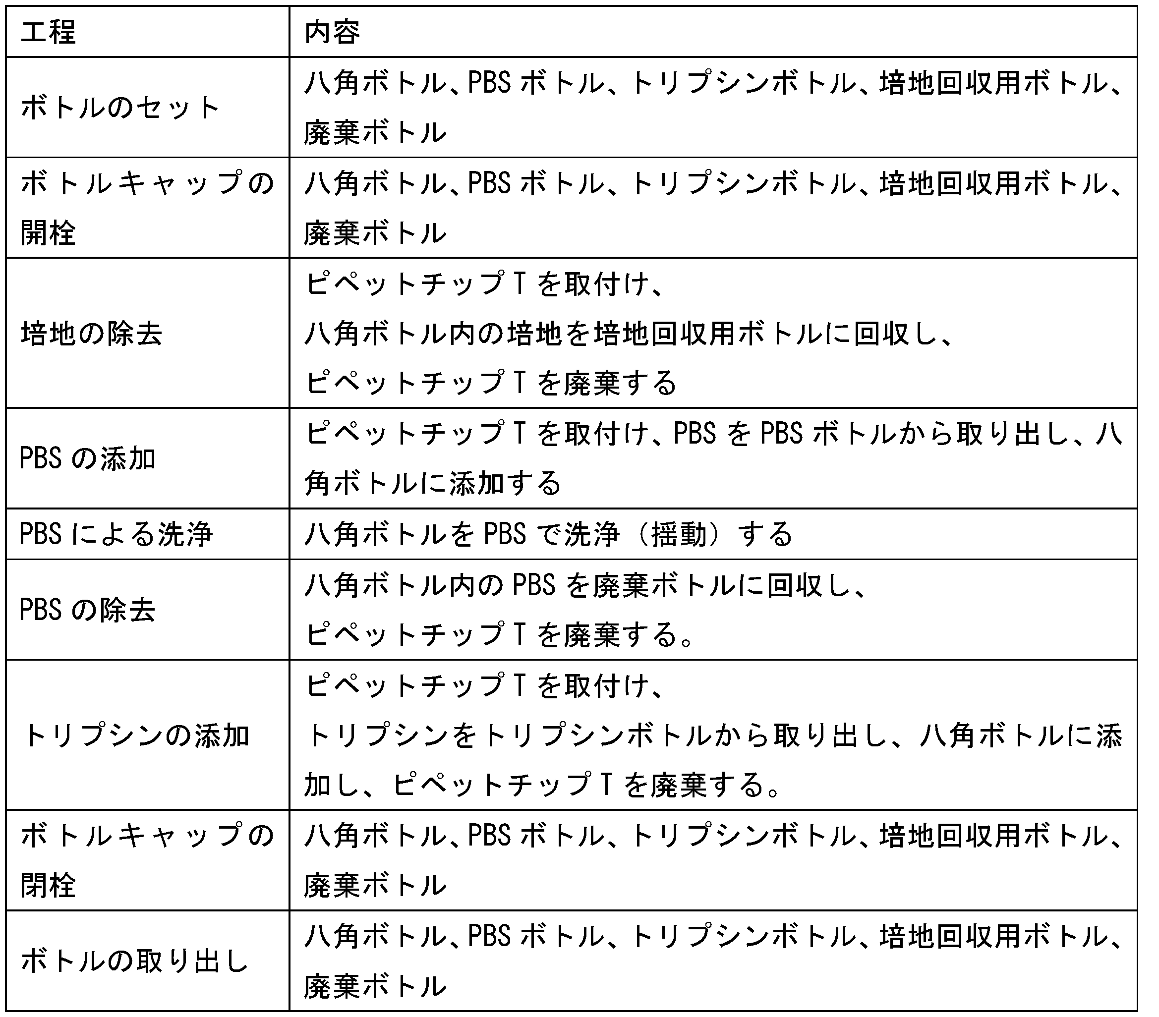
- the cell recovery process can be automatically realized (see Table 2).
- the present invention provides a new culture manipulation device. It is not necessarily the example described in the specific embodiment described above. In addition, a supplementary explanation will be given as follows.
- the working surface 2a of the stage 2 is horizontal, but the present invention is not limited to this. If necessary, the work surface 2a may be set to form a predetermined angle with respect to the horizontal plane.
- all the first bottle C1 can be replaced with the third bottle C3. Specifically, it can be selected as needed.
- the safety cabinet 7 may have a desired power socket and power cord. Further, the housing 71 may have a removable structure for maintenance and a transparent structure for easily observing the internal space.
Landscapes
- Engineering & Computer Science (AREA)
- Health & Medical Sciences (AREA)
- Chemical & Material Sciences (AREA)
- Life Sciences & Earth Sciences (AREA)
- Bioinformatics & Cheminformatics (AREA)
- Wood Science & Technology (AREA)
- Organic Chemistry (AREA)
- Zoology (AREA)
- Biotechnology (AREA)
- Biomedical Technology (AREA)
- Microbiology (AREA)
- Biochemistry (AREA)
- General Engineering & Computer Science (AREA)
- General Health & Medical Sciences (AREA)
- Genetics & Genomics (AREA)
- Sustainable Development (AREA)
- Medicinal Chemistry (AREA)
- Analytical Chemistry (AREA)
- Clinical Laboratory Science (AREA)
- Cell Biology (AREA)
- Virology (AREA)
- Computer Hardware Design (AREA)
- Apparatus Associated With Microorganisms And Enzymes (AREA)
Abstract
複数の容器と、複数のピペットチップと、容器の容器本体及びキャップと複数のピペットチップをそれぞれ載置する載置部材と、異なる容器のキャップを操作することによりキャップとその対応する容器本体の係合作業及び分離作業を実現するキャッパーと、異なるピペットチップを選択的に着脱し、かつ装着されたピペットチップによって容器本体のピペット作業を行うピペット部材と、キャッパーとピペット部材を、載置部材に対して相対的に変位させる移動部材とが設けられるステージと、キャッパーの係合作業及び分離作業、ピペット部材の異なるピペットチップの選択的な着脱及びピペット作業、及び移動部材の相対的な変位の実現を制御する制御部と、無菌の作業環境を提供して、ステージが内部に配置されることにより、載置部材、キャッパー、ピペット部材及び移動部材がすべて作業環境内に置かれる安全キャビネットと、を備える培養操作装置。
Description
本発明は、細胞培養分野、具体的には、培養操作装置に関する。
細胞培養分野では、異なる容器において、培地および/または細胞溶液は精確な量で採取及び注入される必要がある。従来技術では、ほとんどの場合、このような採取作業及び注入作業は作業者の手作業で行われていた。しかし、細胞を用いた製品を作るためには、ある程度の量の細胞が必要となるため細胞培養及び細胞の継代作業を複数回行う必要があるが、細胞継代において複数の種類及び数の容器及びピペットチップを用いて、かつ培地および/または細胞溶液の量を精確に採取及び注入する必要があるため、上記作業が作業者の手作業で行われる場合、非常に高い熟練性が要求される上に、操作が複雑であり、工数がかかる、また作業中にミスが発生しやすいなどの問題があった。
本発明は、上述した従来技術の問題に鑑みてなされたものである。本発明は、細胞培養分野では、作業を人による手作業からロボットを用いて自動化することにより、作業中にミスが発生することを防ぐことができる培養操作装置を提供することを目的とする。
上記目的を達成するために、以下のような発明を採用している。
本発明は、容器本体と、前記容器本体と係合するキャップとを有する複数の容器と、
複数のピペットチップと、
前記容器の容器本体及びキャップと前記複数のピペットチップをそれぞれ載置する載置部材と、異なる前記容器のキャップを操作することにより前記キャップとその対応する前記容器本体の係合作業及び分離作業を実現するキャッパーと、異なる前記ピペットチップを選択的に着脱し、かつ装着された前記ピペットチップによって前記容器本体のピペット作業を行うピペット部材と、前記キャッパーと前記ピペット部材を、前記載置部材に対して、互いに直交する鉛直方向、第1の水平方向及び第2の水平方向との3つの方向に相対的に変位させる移動部材とが設けられるステージと、
所定のプログラムに従って、前記キャッパーの前記係合作業及び分離作業、前記ピペット部材の異なる前記ピペットチップの選択的な着脱及び前記ピペット作業、及び前記移動部材の相対的な変位の実現を制御する制御部と、
無菌の作業環境を提供して、前記ステージが内部に配置されることにより、前記載置部材、前記キャッパー、前記ピペット部材及び前記移動部材がすべて前記作業環境内に置かれる安全キャビネットと、を備える培養操作装置を提供している。
複数のピペットチップと、
前記容器の容器本体及びキャップと前記複数のピペットチップをそれぞれ載置する載置部材と、異なる前記容器のキャップを操作することにより前記キャップとその対応する前記容器本体の係合作業及び分離作業を実現するキャッパーと、異なる前記ピペットチップを選択的に着脱し、かつ装着された前記ピペットチップによって前記容器本体のピペット作業を行うピペット部材と、前記キャッパーと前記ピペット部材を、前記載置部材に対して、互いに直交する鉛直方向、第1の水平方向及び第2の水平方向との3つの方向に相対的に変位させる移動部材とが設けられるステージと、
所定のプログラムに従って、前記キャッパーの前記係合作業及び分離作業、前記ピペット部材の異なる前記ピペットチップの選択的な着脱及び前記ピペット作業、及び前記移動部材の相対的な変位の実現を制御する制御部と、
無菌の作業環境を提供して、前記ステージが内部に配置されることにより、前記載置部材、前記キャッパー、前記ピペット部材及び前記移動部材がすべて前記作業環境内に置かれる安全キャビネットと、を備える培養操作装置を提供している。
好ましくは、前記載置部材は、
その対応する前記容器の容器本体を収容する容器本体収容部と、
前記容器のキャップを載置するキャップ載置部と、
使用前の前記ピペットチップを収容するピペットチップ収容部と、
使用後の前記ピペットチップを回収するピペットチップ回収部と、を備える。
その対応する前記容器の容器本体を収容する容器本体収容部と、
前記容器のキャップを載置するキャップ載置部と、
使用前の前記ピペットチップを収容するピペットチップ収容部と、
使用後の前記ピペットチップを回収するピペットチップ回収部と、を備える。
より好ましくは、前記容器本体収容部は、
その対応する前記容器本体を前記ステージに対して所定の角度で保持する固定収容部と、
その対応する前記容器本体を前記ステージに対して回転可能に保持する可動収容部と、を備える。
その対応する前記容器本体を前記ステージに対して所定の角度で保持する固定収容部と、
その対応する前記容器本体を前記ステージに対して回転可能に保持する可動収容部と、を備える。
より好ましくは、前記可動収容部は、その対応する前記容器本体を前記第1の水平方向および/または前記第2の水平方向に回転させる。なお、「および/または」とは、両者の少なくとも一方という意味であり、いずれか一方及び両方が含まれる。
より好ましくは、前記容器本体収容部には、前記容器の容器本体を挟持する挟持モジュールが設けられており、前記挟持モジュールは、所定の方向で互いに接近または離間する複数の挟持部を有することで、前記複数の挟持部を介して前記容器の容器本体を前記容器本体収容部に対して固定保持する。
より好ましくは、前記キャップ載置部には、各前記キャップの形状と揃えて、それを収容する収納部が形成される。
より好ましくは、前記キャッパーは、係合または分離操作をする時に受けた抵抗を検出するトルク検出部材を備え、前記トルク検出部材の検出したトルクが所定値よりも高い場合に、前記制御部が前記キャッパーの前記キャップに対する操作を停止するように制御する。
より好ましくは、前記ピペット部材は、
前記ピペットチップに挿入して接合することにより、接合された前記ピペットチップを介してピペット作業を行う挿入部と、
前記挿入部に対して移動することにより、前記ピペットチップを前記挿入部から接合解除する除荷部と、を備える。
前記ピペットチップに挿入して接合することにより、接合された前記ピペットチップを介してピペット作業を行う挿入部と、
前記挿入部に対して移動することにより、前記ピペットチップを前記挿入部から接合解除する除荷部と、を備える。
より好ましくは、前記ピペット部材は、前記容器内から定量の溶液を採取するかまたは前記容器へ定量の溶液を注入する微小量定量ピペットユニットをさらに備える。
また、本発明は、容器本体に係合するキャップを有する複数の容器と、
複数のピペットチップと、
前記複数の容器及び前記複数のピペットチップを載置する載置部材と、
各前記キャップと、前記キャップに対応する各前記容器本体との係合作業及び分離作業を行うキャッパーと、
前記複数のピペットチップの中から選択的に前記ピペットチップを着脱可能で、かつ装着された前記ピペットチップを前記容器本体に挿入してピペット作業を行うピペット部材と、
前記キャッパーと前記ピペット部材とを、前記載置部材に対して、相対的に変位させる移動部材と、
前記キャッパーによる前記係合作業及び分離作業と、前記ピペット部材による前記ピペットチップの選択的な着脱及び前記ピペット作業と、前記移動部材の相対的な移動とを制御する制御部と、を備える培養操作装置を提供している。
複数のピペットチップと、
前記複数の容器及び前記複数のピペットチップを載置する載置部材と、
各前記キャップと、前記キャップに対応する各前記容器本体との係合作業及び分離作業を行うキャッパーと、
前記複数のピペットチップの中から選択的に前記ピペットチップを着脱可能で、かつ装着された前記ピペットチップを前記容器本体に挿入してピペット作業を行うピペット部材と、
前記キャッパーと前記ピペット部材とを、前記載置部材に対して、相対的に変位させる移動部材と、
前記キャッパーによる前記係合作業及び分離作業と、前記ピペット部材による前記ピペットチップの選択的な着脱及び前記ピペット作業と、前記移動部材の相対的な移動とを制御する制御部と、を備える培養操作装置を提供している。
好ましくは、前記載置部材、前記キャッパー、及び前記移動部材が設けられたステージと、
内部に無菌の作業環境を形成すると共に、前記内部に前記ステージが前記内部に配置された安全キャビネットと、を備える。
内部に無菌の作業環境を形成すると共に、前記内部に前記ステージが前記内部に配置された安全キャビネットと、を備える。
上記発明により、本発明は以下のような培養操作装置を提供する。該培養操作装置は、ステージと、制御部とを備える。ステージは安全キャビネットの無菌の作業環境にある。ステージには容器の容器本体及びキャップと複数のピペットチップをそれぞれ載置する載置部材と、異なる容器のキャップを操作することによりキャップとその対応する容器本体の係合作業及び分離作業を実現するキャッパーと、異なるピペットチップを選択的に着脱し、かつ装着されたピペットチップによって容器本体のピペット作業を行うピペット部材と、キャッパーとピペット部材を、載置部材に対して、少なくとも互いに直交する3つの方向に相対的に変位させる移動部材とが設けられている。上述の構造により、制御部は、所定のプログラムに従って、キャッパーの係合作業及び分離作業、ピペット部材の異なるピペットチップの選択的な着脱及び精確な量でのピペット作業を正確に制御できるとともに、移動部材による相対的な変位を精確に制御できるため、細胞培養分野で作業を人による手作業からロボットを用いて自動化することにより、作業中にミスが発生することを防ぐことができる。
本発明によれば、細胞培養分野における作業中にミスが発生することを防ぐことができる。
以下、図面を参照して、本発明の例示的な実施形態について説明する。これらの具体的な説明は、どのように本発明を実施するかについての教示を当業者に与えるだけであり、本発明のすべての可能な形態を一々挙げるのではなく、本発明の範囲を限定するものでもないと理解すべきである。なお、本発明において、「鉛直方向」とは地球の重力方向(図1の上下方向)を指し、「第1の水平方向」及び「第2の水平方向」とは上記鉛直方向に直交する平面内における互いに直交する2つの方向を指す(第1の水平方向は図1の左右方向及び図2の上下方向、第2の水平方向は図2の左右方向である)。
以下、本発明の一つの実施形態に係る培養操作装置の構造について説明する。
(本発明の一つの実施形態に係る培養操作装置の構造)
(本発明の一つの実施形態に係る培養操作装置の構造)
図1~図6に示すように、本発明の一つの実施形態に係る培養操作装置は、安全キャビネット7と、安全キャビネット7の外部に設けられた制御部1と、安全キャビネット7の内部に設けられた複数の容器C、複数のピペットチップT、ステージ2、載置部材3、キャッパー4、ピペット部材5及び移動部材6とを備えている。
本実施形態では、容器Cは、細胞培養用の培地や細胞溶液などを収容するための容器である。図1、図2、図3及び図4に示すように、各容器Cのそれぞれは、収容空間を形成する容器本体CBと、容器本体CBの開口を閉栓するためのキャップCLとを有する(図4参照)。具体的には、容器Cは、第1のボトルC1と、第2のボトルC2と、第3のボトルC3とに分かれている。第1のボトルC1は、容器本体CBの横断面が円形となるボトルである(本実施形態では、5つある)。第1のボトルC1はすべて固定収容部311に収容されている。第2のボトルC2は、容器本体CBの横断面が長方形となるボトルである(本実施形態では、1つある)。第2のボトルC2は可動収容部312に収容され、かつ多層細胞培養ボトルであってもよい。該第2のボトルC2の内部は、ロート構造や培地及び細胞溶液の集中、流動及び分布に有利な他の構造を有してもよい。第3のボトルC3は、容器本体CBの横断面が正八角形となるボトルである(本実施形態では、2つある)。一方の第3のボトルC3は固定収容部311に収容され、他方の第3のボトルC3は可動収容部312に収容されている。
本実施形態では、複数のピペットチップTはピペット部材5と協働して異なる容器Cから培地及び細胞溶液を定量で採取し、かつ採取した培地及び細胞溶液を他の容器C内に注入することにより、定量のピペット作業を実現する。各ピペットチップTはピペット部材5の挿入部51と合う開口を有し、かつ各ピペットチップTの下端部は下端に向かうテーパ形状となる。
本実施形態では、ステージ2は安全キャビネット7内の作業台72上に設置されている(図1、図2及び図6参照)。ステージ2は、水平方向に沿って延在している作業面2aを有する。作業面2aには、載置部材3、キャッパー4、ピペット部材5及び移動部材6が設置されている。
具体的には、本実施形態では、載置部材3は、容器Cの容器本体CB、キャップCL及び複数のピペットチップTをそれぞれ載置するために設けられている。容器Cの容器本体CB、キャップCL及び複数のピペットチップTのそれぞれに対応して、載置部材3は、容器本体収容部31と、キャップ載置部32と、ピペットチップ収容部33と、ピペットチップ回収部34とを有する。
さらに、容器本体収容部31は、その対応する容器Cの容器本体CBを収容し、かつ容器本体CBの断面形状と合う収容空間を有する。複数の容器本体収容部31は第1の水平方向H1及び第2の水平方向H2において並んで配置されることにより、できるだけ空間を節約し、かつ作業の便宜を図ることができる。容器本体収容部31は、作業面2aに対して回動不可な固定収容部311及び作業面2aに対して回動可能な可動収容部312を有する。
固定収容部311は、その対応する容器本体CBを作業面2aに対して所定の角度となるように保持する。本実施形態では、固定収容部311は、その対応する容器本体CBをその中心軸が作業面2aに対して直交するように保持する。つまり、該容器本体CBの中心軸は鉛直方向Vに沿っている。この直交とは、「所定の角度」の一例である。このように、固定収容部311によって収容された容器本体CBの開口は常に鉛直方向Vの上方に向かっていることにより、ピペット部材5はピペットチップTを用いて容器本体CBの上方から容器本体CB内に進入して採取作業及び注入作業を行うことができる。また、各固定収容部311には、容器Cの容器本体CBを挟持する挟持モジュールが設けられている。挟持モジュールは、第1の水平方向H1において互いに接近または離間する2つの挟持部313を有することで、2つの挟持部313によって容器Cの容器本体CBを固定保持し、容器本体CBを容器本体収容部31に対して固定することができる。このように、キャッパー4によって容器CのキャップCLを操作してキャップCLを容器本体CBと係合または分離する過程では、容器本体CBはキャッパー4の操作に伴って回転自在とならない。
可動収容部312は、その対応する容器本体CBを作業面2aに対して回動可能に保持する。本実施形態では、第2のボトルC2を収容するための可動収容部312は、第1の水平方向H1周りに回転可能であるため、第2のボトルC2の中心軸は第1の水平方向H1周りに作業面2aに対して所定の角度となることが可能である。一方の第3のボトルC3を収容するための可動収容部312は、第1の水平方向H1及び第2の水平方向H2周りに回転可能であるため、当該第3のボトルC3の中心軸は第1の水平方向H1及び第2の水平方向H2周りに作業面2aに対して所定の角度となることが可能である。必要な場合、第2のボトルC2及び第3のボトルC3の中心軸は水平面と平行に配置されてもよく、第2のボトルC2及び第3のボトルC3は各々の軸周りに回動可能に配置されてもよい。このように、培地及び細胞溶液を第2のボトルC2及び第3のボトルC3に注入することに有利であり、かつ培地及び細胞溶液を均一に混合して分布することにも有利である。
さらに、キャップ載置部32は、容器Cから外されたキャップCLを載置するために設けられている。本実施形態では、キャップ載置部32には、各キャップCLの形状と合う凹部321(収納部)が形成されていることにより、凹部321はその対応するキャップCLを収容可能である。また、システムが外されたキャップCL及びその対応する凹部321を容易に識別するように、キャップ載置部32に形成された凹部321の分布は容器本体収容部31の分布と一致している。つまり、本実施形態では、キャップ載置部32の凹部321と容器C収容部のキャップCLとは位置がそれぞれ対応し、かつ各凹部321とその対応するキャップCLとの第2の水平方向H2での距離とは等しいことで、その対応するキャップCLをその対応する凹部321内に入れる。
また、複数の容器Cの少なくとも一部のキャップCLの外周壁には、径方向外側に突起する位置決め凸部(図示なし)が形成され、該キャップCLと合う凹部321の内周壁には、位置決め凸部と合う位置決め凹部(図示なし)が形成されている。このように、上記位置決め凸部はキャッパー4によるキャップCLの操作に有利である一方、上記位置決め凸部は位置決め凹部と合うしてキャップCLを凹部321内に確実に保持することができる。
さらに、ピペットチップ収容部33は使用前のピペットチップTを収容するために設けられている。本実施形態では、ピペットチップ収容部33は8つあり、かつ第1の水平方向H1及び第2の水平方向H2においてアレイ状に配列されていることにより、使用前のピペットチップTは1つの領域内にコンパクトに位置し、管理されやすい。ピペットチップ回収部34は使用後のピペットチップTを回収するために設けられている。本実施形態では、ピペットチップ収容部33と同じように、ピペットチップ回収部34は8つあり、かつ第1の水平方向H1及び第2の水平方向H2においてアレイ状に配列されていることにより、使用後のピペットチップTは1つの領域内にコンパクトに位置し、管理されやすい。
本実施形態では、キャッパー4は、異なる容器CのキャップCLを操作することにより、キャップCLとその対応する容器本体CBの係合作業及び分離作業を実現するために設けられている。キャッパー4は、容器CのキャップCLと係合可能であり、かつ鉛直方向V周りに2方向回転可能な係合爪41を有する。係合爪41は、キャップCLの周方向に均一に分布する3つの爪部411を有することにより、容器CのキャップCLを締め付けるかまたは緩めることができる。係合爪41は、外側から容器Cの容器本体CBに取り付けられたキャップCLと係合した後、1つの方向に回動すればキャップCLを容器本体CBから外し、キャップCLと容器本体CBとを分離させることができる。一方、係合爪41は、キャップCLと容器本体CBとを係合させることにより、容器本体CBの開口を閉栓することができる。キャッパー4は、係合爪41を2方向回転させる回転モジュール42をさらに有する。回転モジュール42は、トルクの大きさに応じてキャップCLが容器本体CBと確実に係合するか否かを判断することが可能である。また、キャッパー4は、係合爪41が鉛直方向V周りに回転する時に受けたトルク(抵抗)を検出可能なトルク検出部材をさらに備える。係合爪41がキャップCLを容器本体CBにねじ込む場合、トルク検出部材の検出したトルクが所定値よりも高いと、キャップCLは容器本体CBに確実に係合したことを意味している。このとき、制御部1はキャップCLから離すように係合爪41を制御する。つまり、制御部1は、キャッパー4のキャップCLに対する作業を停止するように制御する。係合爪41が位置決め凸部付きのキャップCLを凹部321に載置する場合、最初にそれを凹部321に載置するとき、必ずキャップCLと凹部321がピッタリ係合する位相に載置するとは限らない。この場合、係合爪41はキャップCLに下方に向かう一定の圧力を付加しながら回転する。キャップCLと凹部321がピッタリ係合する位相に回転すると、キャップCLは係合爪41による下方への圧力によって凹部321内に押し込まれる。すると、係合爪41はキャップCLの位置決め凸部の阻止作用によってキャップCLを引き続き回転させることができない。このとき、トルク検出部材の検出したトルクが所定値よりも高いことで、制御部1はキャップCLから離して戻るように係合爪41を制御する。なお、係合爪41がキャップCLを容器本体CBにねじ込む際に、係合爪41はまずキャップCLを緩める方向に向かって一定の角度で回転させ(ねじの各パラメーターに応じてその角度の大きさを特定し)、キャップCLのねじと容器本体CBのねじとを係合させてから、キャップCLを締付け方向に向かって回転させて締め付ける。該トルクの所定値について、例えばキャップ載置部32の表面粗さなどの条件に応じて、以下のように設定する必要がある。該所定値は、係合爪41がキャップCLをキャップ載置部32の表面に押圧して回転させる時に克服すべき摩擦力のトルクよりも大きく、かつキャッパー4が阻止されて回転し続けない時にその駆動モータの負荷が高すぎて損傷が発生する場合のトルクよりも小さい。
本実施形態では、ピペット部材5は、異なるピペットチップTを選択的に着脱し、かつ装着されたピペットチップTによって容器本体CBのピペット作業を行う。ピペット部材5は、組み立てられた挿入部51及び除荷部52を含む。
具体的には、挿入部51は、円柱形となり、かつ鉛直方向Vに沿って延在している。挿入部51は、ピペットチップTの内径と合う外径を有することで、ピペットチップT内に挿入し、締まり嵌めによって該ピペットチップTに確実に接合することができる。また、挿入部51には、吸入力及び吐出力を発生させることにより、挿入部51に接合したピペットチップTのピペット作業を行うことが可能となるピペット孔がさらに設けられている。
除荷部52は、該挿入部51に外嵌し、かつ鉛直方向Vに沿って挿入部51に対して移動可能である。除荷部52と挿入部51との相対的な移動により、ピペットチップTを挿入部51から取り外すことができる。つまり、挿入部51に対して移動する除荷部52は、ピペットチップTを支えてピペットチップTと挿入部51とを分離(接合解除)させることができる。
さらに、ピペット部材5は、ピペットチップTに接合せず、容器C内から定量の溶液を採取する微小量定量ピペットユニット53をさらに有する。該微小量定量ピペットユニット53は、培地及び細胞溶液に対して微小量の液体採取作業を行う液体採取ヘッドを有する。また、液体採取ヘッドは他の各用途にも適用できる。
本実施形態では、移動部材6は、キャッパー4及びピペット部材5を、載置部材3に対して互いに直交する鉛直方向V、第1の水平方向H1及び第2の水平方向H2の3つの方向に相対的に変位させる。具体的には、移動部材6は、フレームと、フレームに設けられた3つの移動レールRv,Rh1,Rh2とを有する。3つのレールRv,Rh1,Rh2はそれぞれ鉛直方向V、第1の水平方向H1及び第2の水平方向H2との3つの方向に沿って延びている。また、移動部材6は、載置部材3を第1の水平方向H1に沿って延びているレールRh1に沿って所定の範囲内に変位させる機構と、キャッパー4及びピペット部材5を第2の水平方向H2に沿って延びているレールRh2及び鉛直方向Vに沿って延びているレールRvに沿って所定の範囲内に変位させる機構とを有する。このように、該移動機構により、キャッパー4を各容器C及びキャップ載置部32の各凹部321と位置合わせし、かつピペット部材5を各ピペットチップT、各ピペットチップ回収部34及び各容器Cの容器本体CBと位置合わせすることで、所望の各作業をスムーズに行うことができる。
本実施形態では、制御部1は、CPUやメモリ等を備えており、移動部材6、キャッパー4、及びピペット部材5に有線または無線によって制御信号を送受信可能に接続されている。制御部1は、メモリに格納されている所定のプログラムに従って、移動部材6の相対的な変位の実現、キャッパー4の係合作業及び分離作業、ピペット部材5の異なるピペットチップTの選択的な着脱及びピペット作業を制御することが可能である。具体的には、制御部1は、全体制御ユニット11と、ピペット制御ユニット12と、回転制御ユニット13と、キャップ回転制御ユニット14と、シリンダ制御ユニット15とを有する。これら制御ユニットは各部材の動作を制御することにより、所定のプログラムに従って上記各作業を行う。
本実施形態では、図5及び図6に示すように、安全キャビネット7は、無菌の作業環境を提供するために設けられている。ステージ2は安全キャビネット7内の着脱可能な作業台72に設置されている。安全キャビネット7は、筺体71と、排気モジュール73と、測定モジュール74と、殺菌モジュール75と、照明モジュール76と、移動調整モジュール77とを有する。
具体的には、本実施形態では、筺体71は、立方体形状となり、かつ内部に無菌の作業環境を形成する。作業台72は筺体71内に取り付けられ、かつ水平に配置されている。
さらに、本実施形態では、排気モジュール73は、筺体71の内部と外部とを連通するために設けられている。排気モジュール73は、筺体71に設けられた給気口731及び排気口735と、筺体71に設けられ、給気口731に位置する給気フィルタ732(本実施形態では、2枚ある)と、筺体71に設けられ、排気口735に位置する排気フィルタ734(本実施形態では、1枚ある)とを有することにより、筺体71内外の気体交換時にダスト及び粒子などを濾過する。排気モジュール73は、排気口735の内側に設けられた送風機733をさらに有する。該送風機733は、筺体71内外の空気交換を促進するために設けられている。また、排気モジュール73は、排気フィルタ734の圧力差を監視する排気フィルタ差圧計736をさらに有する。
さらに、本実施形態では、測定モジュール74は、筺体71内の所定のパラメーターを測定するために設けられている。具体的には、測定モジュール74は、筺体71内のダスト及び粒子の濃度を測定するパーティクルカウンタ741と、PAO(ポリアルファオレフィン)の入力を測定するPAO入口側測定バルブ742とを有することにより、ユーザに所望のパラメーター情報を提供することができる。
さらに、本実施形態では、殺菌モジュール75は筺体71に設けられ、かつ筺体71の内部を殺菌処理するために設けられている。具体的には、殺菌モジュール75は、筺体71の側壁に設けられた2つの殺菌灯(15W)を有することにより、筺体71の内部空間を効果的に殺菌することができる。
さらに、本実施形態では、照明モジュール76は筺体71の内部を照明するために設けられている。具体的には、照明モジュール76は筺体71の内部空間の頂部に設けられた3つのLEDを含む。
さらに、本実施形態では、移動調整モジュール77は筺体71の下部に配置され、筺体71を移動させ、かつ筺体71と地面との角度を調整するために設けられている。具体的には、移動調整モジュール77は、複数のローラ771と、複数のアジャスタ772と、複数の支持脚773とを有する。ローラ771は、筺体71が移動時に地面に進むことに有利である。アジャスタ772は、筺体71を支持する一方、筺体71と地面との角度を調整するために設けられている。支持脚773は下に置かれた後、筺体71に対して支持作用を果たす。
さらに、本実施形態では、操作表示部78は筺体71の外壁に配置され、筺体71内のパラメーターを表示し、かつ安全キャビネット7の各部材の動作を制御する操作指令などを入力するために設けられている。
以上は、本発明の一つの実施形態に係る培養操作装置の構造についての説明である。以下では、例を挙げて上記培養操作装置の動作工程の例示について説明する。以下の動作工程の例示はすべて所定のプログラムに従って本発明に係る培養操作装置によって少なくとも一部の工程が自動的に完成可能である。
(本発明の一つの実施形態に係る培養操作装置の動作工程の例示)
(本発明の一つの実施形態に係る培養操作装置の動作工程の例示)
なお、下記動作工程の例示において、八角ボトルは上記第3のボトルC3であり、培養ボトル、培地回収用ボトル、PBSボトル、トリプシンボトル、廃液ボトルとして上記第1のボトルC1または第2のボトルC2を選択することが可能である。
1つの例示において、培地交換の動作工程が自動的に実現できる(表1参照)。

別の例示において、細胞回収工程が自動的に実現できる(表2参照)。
したがって、本発明は、新たな培養操作装置を提供する。それは上述した具体的な実施形態で記載した例示とは限らない。また、以下のとおり補足説明する。
(i)上述した具体的な実施形態では、本発明に係る培養操作装置の動作工程の2つの例示のみ挙げられているが、本発明に係る培養操作装置は上記2つの例示を実現できるだけではなく、所定のプログラムに従って、所望の他の培地のピペット処理及び細胞培養工程も実現できる。
(ii)上述した具体的な実施形態では、ステージ2の作業面2aが水平であることについて説明したが、本発明はそれとは限らない。必要に応じて、作業面2aを、水平面に対して所定の角度をなすように設定してもよい。
(iii)本発明において、第1のボトルC1をすべて第3のボトルC3で代替することができる。具体的には、必要に応じてそれを選択することができる。
(iv)上述した具体的な実施形態では、本発明に係る培養操作装置の安全キャビネット7の構造について説明したが、本発明はそれとは限らない。該安全キャビネット7は、所望の電源ソケット及び電源コードを有してもよい。また、筺体71は、メンテナンス用の着脱可能な構造、及び内部空間を容易に観察する透明構造を有してよい。
1 制御部、11 全体制御ユニット、12 ピペット制御ユニット、13 回転制御ユニット、14 キャップ回転制御ユニット、15 シリンダ制御ユニット、
2 ステージ、2a 作業面、
3 載置部材、31 容器本体収容部、311 固定収容部、312 可動収容部、313 挟持部、32 キャップ載置部、321 凹部、33 ピペットチップ収容部、34 ピペットチップ回収部、
4 キャッパー、41 係合爪、411 爪部、42回転モジュール、
5 ピペット部材、51 挿入部、52 除荷部、53 微小量定量ピペットユニット、
6 移動部材、
7 安全キャビネット、71 筺体、72 作業台、73 排気モジュール、731 給気口、732 給気フィルタ、733 送風機、734 排気フィルタ、735 排気口、736 排気フィルタ差圧計、74 測定モジュール、741 パーティクルカウンタ、742 PAO入口側測定バルブ、75 殺菌モジュール、76 照明モジュール、77 移動調整モジュール、771 ローラ、772 アジャスタ、773 支持脚、78 操作表示部、
C 容器、C1 第1のボトル、C2 第2のボトル、C3 第3のボトル、CB 容器本体、CL キャップ、T ピペットチップ、
V 鉛直方向、H1 第1の水平方向、H2 第2の水平方向
2 ステージ、2a 作業面、
3 載置部材、31 容器本体収容部、311 固定収容部、312 可動収容部、313 挟持部、32 キャップ載置部、321 凹部、33 ピペットチップ収容部、34 ピペットチップ回収部、
4 キャッパー、41 係合爪、411 爪部、42回転モジュール、
5 ピペット部材、51 挿入部、52 除荷部、53 微小量定量ピペットユニット、
6 移動部材、
7 安全キャビネット、71 筺体、72 作業台、73 排気モジュール、731 給気口、732 給気フィルタ、733 送風機、734 排気フィルタ、735 排気口、736 排気フィルタ差圧計、74 測定モジュール、741 パーティクルカウンタ、742 PAO入口側測定バルブ、75 殺菌モジュール、76 照明モジュール、77 移動調整モジュール、771 ローラ、772 アジャスタ、773 支持脚、78 操作表示部、
C 容器、C1 第1のボトル、C2 第2のボトル、C3 第3のボトル、CB 容器本体、CL キャップ、T ピペットチップ、
V 鉛直方向、H1 第1の水平方向、H2 第2の水平方向
Claims (11)
- 容器本体と、前記容器本体と係合するキャップとを有する複数の容器と、
複数のピペットチップと、
前記容器の容器本体及びキャップと前記複数のピペットチップをそれぞれ載置する載置部材と、異なる前記容器のキャップを操作することにより前記キャップとその対応する前記容器本体の係合作業及び分離作業を実現するキャッパーと、異なる前記ピペットチップを選択的に着脱し、かつ装着された前記ピペットチップによって前記容器本体のピペット作業を行うピペット部材と、前記キャッパーと前記ピペット部材を、前記載置部材に対して、互いに直交する鉛直方向、第1の水平方向及び第2の水平方向との3つの方向に相対的に変位させる移動部材とが設けられるステージと、
所定のプログラムに従って、前記キャッパーの前記係合作業及び分離作業、前記ピペット部材の異なる前記ピペットチップの選択的な着脱及び前記ピペット作業、及び前記移動部材の相対的な変位の実現を制御する制御部と、
無菌の作業環境を提供して、前記ステージが内部に配置されることにより、前記載置部材、前記キャッパー、前記ピペット部材及び前記移動部材がすべて前記作業環境内に置かれる安全キャビネットと、を備えることを特徴とする培養操作装置。 - 前記載置部材は、
前記容器の容器本体を収容する容器本体収容部と、
前記容器のキャップを載置するキャップ載置部と、
使用前の前記ピペットチップを収容するピペットチップ収容部と、
使用後の前記ピペットチップを回収するピペットチップ回収部と、を備えることを特徴とする請求項1に記載の培養操作装置。 - 前記容器本体収容部は、
その対応する前記容器本体を前記ステージに対して所定の角度で保持する固定収容部と、
その対応する前記容器本体を前記ステージに対して回転可能に保持する可動収容部と、を備えることを特徴とする請求項2に記載の培養操作装置。 - 前記可動収容部は、その対応する前記容器本体を前記第1の水平方向および/または前記第2の水平方向に回転させることを特徴とする請求項3に記載の培養操作装置。
- 前記容器本体収容部には、前記容器の容器本体を挟持する挟持モジュールが設けられており、前記挟持モジュールは、所定の方向で互いに接近または離間する複数の挟持部を有することで、前記複数の挟持部を介して前記容器の容器本体を前記容器本体収容部に対して固定保持することを特徴とする請求項2に記載の培養操作装置。
- 前記キャップ載置部には、各前記キャップの形状と揃えて、それを収容する収納部が形成されることを特徴とする請求項2に記載の培養操作装置。
- 前記キャッパーは、係合作業または分離作業をする時に受けた抵抗を検出するトルク検出部材を備え、前記トルク検出部材の検出したトルクが所定値よりも高い場合に、前記制御部が前記キャッパーの前記キャップに対する作業を停止するように制御することを特徴とする請求項1~6のいずれか一項に記載の培養操作装置。
- 前記ピペット部材は、
前記ピペットチップに挿入して接合することにより、接合された前記ピペットチップを介してピペット作業を行う挿入部と、
前記挿入部に対して移動することにより、前記ピペットチップを前記挿入部から接合解除する除荷部と、を備えることを特徴とする請求項1~6のいずれか一項に記載の培養操作装置。 - 前記ピペット部材は、前記容器内から定量の溶液を採取するかまたは前記容器へ定量の溶液を注入する微小量定量ピペットユニットをさらに備えることを特徴とする請求項8に記載の培養操作装置。
- 容器本体に係合するキャップを有する複数の容器と、
複数のピペットチップと、
前記複数の容器及び前記複数のピペットチップを載置する載置部材と、
各前記キャップと、前記キャップに対応する各前記容器本体との係合作業及び分離作業を行うキャッパーと、
前記複数のピペットチップの中から選択的に前記ピペットチップを着脱可能で、かつ装着された前記ピペットチップを前記容器本体に挿入してピペット作業を行うピペット部材と、
前記キャッパーと前記ピペット部材とを、前記載置部材に対して、相対的に変位させる移動部材と、
前記キャッパーによる前記係合作業及び分離作業と、前記ピペット部材による前記ピペットチップの選択的な着脱及び前記ピペット作業と、前記移動部材の相対的な移動とを制御する制御部と、を備えることを特徴とする培養操作装置。 - 前記載置部材、前記キャッパー、及び前記移動部材が設けられたステージと、
内部に無菌の作業環境を形成すると共に、前記内部に前記ステージが前記内部に配置された安全キャビネットと、を備えることを特徴とする請求項10記載の培養操作装置。
Priority Applications (1)
| Application Number | Priority Date | Filing Date | Title |
|---|---|---|---|
| JP2022508727A JPWO2021187610A1 (ja) | 2020-03-18 | 2021-03-18 |
Applications Claiming Priority (2)
| Application Number | Priority Date | Filing Date | Title |
|---|---|---|---|
| CN202010192454.9 | 2020-03-18 | ||
| CN202010192454.9A CN113493734A (zh) | 2020-03-18 | 2020-03-18 | 培养操作装置 |
Publications (1)
| Publication Number | Publication Date |
|---|---|
| WO2021187610A1 true WO2021187610A1 (ja) | 2021-09-23 |
Family
ID=77768164
Family Applications (1)
| Application Number | Title | Priority Date | Filing Date |
|---|---|---|---|
| PCT/JP2021/011263 Ceased WO2021187610A1 (ja) | 2020-03-18 | 2021-03-18 | 培養操作装置 |
Country Status (3)
| Country | Link |
|---|---|
| JP (1) | JPWO2021187610A1 (ja) |
| CN (1) | CN113493734A (ja) |
| WO (1) | WO2021187610A1 (ja) |
Cited By (1)
| Publication number | Priority date | Publication date | Assignee | Title |
|---|---|---|---|---|
| WO2025142790A1 (ja) * | 2023-12-26 | 2025-07-03 | 三菱重工業株式会社 | フラスコトレイ、フラスコユニット及び細胞培養システム |
Family Cites Families (3)
| Publication number | Priority date | Publication date | Assignee | Title |
|---|---|---|---|---|
| JP2004305148A (ja) * | 2003-04-09 | 2004-11-04 | Olympus Corp | 自動培養装置 |
| WO2016170623A1 (ja) * | 2015-04-22 | 2016-10-27 | 株式会社安川電機 | 細胞培養システム及び細胞培養方法 |
| CN209890608U (zh) * | 2019-03-14 | 2020-01-03 | 广州蓝勃生物科技有限公司 | 一种培养皿开合盖装置 |
-
2020
- 2020-03-18 CN CN202010192454.9A patent/CN113493734A/zh active Pending
-
2021
- 2021-03-18 JP JP2022508727A patent/JPWO2021187610A1/ja active Pending
- 2021-03-18 WO PCT/JP2021/011263 patent/WO2021187610A1/ja not_active Ceased
Non-Patent Citations (4)
| Title |
|---|
| ANONYMOUS: "iPS cell automatic culture device-faithfully reproduces the culture technology of experts Accelerate research in the fields of regenerative medicine and drug discovery", PANASONIC - NEWS, 28 February 2018 (2018-02-28), XP055859351, Retrieved from the Internet <URL:https://news.panasonic.com/jp/stories/2018/55493.html> [retrieved on 20210422] * |
| ANONYMOUS: "Technology that support Decode: fully-automated cell culture device", RIKEN, 19 February 2020 (2020-02-19), Retrieved from the Internet <URL:https://webarchive.org/web/20200219084735/https://decode.riken.jp:80/jp/technology/tech_culture.html> [retrieved on 20210422] * |
| CHANNEL PANASONIC - OFFICIAL: "IPS", YOUTUBE, 28 February 2018 (2018-02-28), XP055859503, Retrieved from the Internet <URL:https://www.youtube.com/watch?v=RtxGCWC7N54> [retrieved on 20210422] * |
| LAB FRUSAWA: "Fully-automated culture system in Furusawa Lab", YOUTUBE, 19 May 2016 (2016-05-19), XP055859518, Retrieved from the Internet <URL:https://www.youtube.com/watch?v=4k6qCN7ppsk> [retrieved on 20210422] * |
Cited By (1)
| Publication number | Priority date | Publication date | Assignee | Title |
|---|---|---|---|---|
| WO2025142790A1 (ja) * | 2023-12-26 | 2025-07-03 | 三菱重工業株式会社 | フラスコトレイ、フラスコユニット及び細胞培養システム |
Also Published As
| Publication number | Publication date |
|---|---|
| CN113493734A (zh) | 2021-10-12 |
| JPWO2021187610A1 (ja) | 2021-09-23 |
Similar Documents
| Publication | Publication Date | Title |
|---|---|---|
| KR102489816B1 (ko) | 살균 용액 제품 백들을 생산하는 방법 및 기계 | |
| EP2285337B1 (en) | Automated workstation for the secure preparation of a final product for medical or pharmaceutical use | |
| CN112940917A (zh) | 自动化细胞培养设备 | |
| WO2012141055A1 (ja) | 細胞培養装置、及び搬送装置 | |
| CN110480391A (zh) | 一种适用于大型复杂工件加工和装配的自动换刀系统 | |
| CN109534254A (zh) | 一种包装瓶机器人自动拧盖生产线 | |
| WO2021187610A1 (ja) | 培養操作装置 | |
| JP2012504427A (ja) | 細胞及び/又はバクテリア培養用の培養/暴露装置 | |
| JP2017503147A (ja) | 車両用キャニスター検査装置 | |
| CN115494803A (zh) | 一种全流程集成化药品研发工作站 | |
| US20050145295A1 (en) | Adjustable needle filling and laser sealing apparatus and method | |
| CN100590433C (zh) | 试样分析仪的试样传送方法和试样瓶操作系统 | |
| CN211393828U (zh) | 一种慢病毒载体无菌分装系统 | |
| CN219016836U (zh) | 一种全流程集成化药品研发工作站 | |
| CN118992167A (zh) | 透析干粉桶自动灌装机 | |
| CN116021274B (zh) | 安全阀装配机 | |
| JP2009190154A (ja) | 全自動細穴加工システム | |
| JP7813699B2 (ja) | 細胞回収装置用ロボット及び細胞回収方法 | |
| CN116445272A (zh) | 一种自动化集菌系统 | |
| JP7756074B2 (ja) | 細胞回収装置及び細胞回収方法 | |
| CN224019414U (zh) | 一种用于甲醛密闭取样的装置 | |
| CN112894358B (zh) | 一种玻璃移液管全自动组装设备 | |
| CN220542858U (zh) | 药品检测滴定装置 | |
| CN222717993U (zh) | 一种具有气体泄漏检测功能的特气柜 | |
| US20260056092A1 (en) | Sampling system and sampling method |
Legal Events
| Date | Code | Title | Description |
|---|---|---|---|
| 121 | Ep: the epo has been informed by wipo that ep was designated in this application |
Ref document number: 21772256 Country of ref document: EP Kind code of ref document: A1 |
|
| ENP | Entry into the national phase |
Ref document number: 2022508727 Country of ref document: JP Kind code of ref document: A |
|
| NENP | Non-entry into the national phase |
Ref country code: DE |
|
| 122 | Ep: pct application non-entry in european phase |
Ref document number: 21772256 Country of ref document: EP Kind code of ref document: A1 |