WO2021187440A1 - 空気調和機 - Google Patents
空気調和機 Download PDFInfo
- Publication number
- WO2021187440A1 WO2021187440A1 PCT/JP2021/010436 JP2021010436W WO2021187440A1 WO 2021187440 A1 WO2021187440 A1 WO 2021187440A1 JP 2021010436 W JP2021010436 W JP 2021010436W WO 2021187440 A1 WO2021187440 A1 WO 2021187440A1
- Authority
- WO
- WIPO (PCT)
- Prior art keywords
- air conditioner
- wall
- space
- outer housing
- outdoor
- Prior art date
- Legal status (The legal status is an assumption and is not a legal conclusion. Google has not performed a legal analysis and makes no representation as to the accuracy of the status listed.)
- Ceased
Links
Images







Classifications
-
- F—MECHANICAL ENGINEERING; LIGHTING; HEATING; WEAPONS; BLASTING
- F24—HEATING; RANGES; VENTILATING
- F24F—AIR-CONDITIONING; AIR-HUMIDIFICATION; VENTILATION; USE OF AIR CURRENTS FOR SCREENING
- F24F1/00—Room units for air-conditioning, e.g. separate or self-contained units or units receiving primary air from a central station
- F24F1/06—Separate outdoor units, e.g. outdoor unit to be linked to a separate room comprising a compressor and a heat exchanger
- F24F1/60—Arrangement or mounting of the outdoor unit
- F24F1/62—Wall-mounted
-
- F—MECHANICAL ENGINEERING; LIGHTING; HEATING; WEAPONS; BLASTING
- F24—HEATING; RANGES; VENTILATING
- F24F—AIR-CONDITIONING; AIR-HUMIDIFICATION; VENTILATION; USE OF AIR CURRENTS FOR SCREENING
- F24F1/00—Room units for air-conditioning, e.g. separate or self-contained units or units receiving primary air from a central station
- F24F1/06—Separate outdoor units, e.g. outdoor unit to be linked to a separate room comprising a compressor and a heat exchanger
- F24F1/56—Casing or covers of separate outdoor units, e.g. fan guards
-
- F—MECHANICAL ENGINEERING; LIGHTING; HEATING; WEAPONS; BLASTING
- F24—HEATING; RANGES; VENTILATING
- F24F—AIR-CONDITIONING; AIR-HUMIDIFICATION; VENTILATION; USE OF AIR CURRENTS FOR SCREENING
- F24F1/00—Room units for air-conditioning, e.g. separate or self-contained units or units receiving primary air from a central station
- F24F1/0003—Room units for air-conditioning, e.g. separate or self-contained units or units receiving primary air from a central station characterised by a split arrangement, wherein parts of the air-conditioning system, e.g. evaporator and condenser, are in separately located units
-
- F—MECHANICAL ENGINEERING; LIGHTING; HEATING; WEAPONS; BLASTING
- F24—HEATING; RANGES; VENTILATING
- F24F—AIR-CONDITIONING; AIR-HUMIDIFICATION; VENTILATION; USE OF AIR CURRENTS FOR SCREENING
- F24F1/00—Room units for air-conditioning, e.g. separate or self-contained units or units receiving primary air from a central station
- F24F1/06—Separate outdoor units, e.g. outdoor unit to be linked to a separate room comprising a compressor and a heat exchanger
- F24F1/36—Drip trays for outdoor units
-
- F—MECHANICAL ENGINEERING; LIGHTING; HEATING; WEAPONS; BLASTING
- F24—HEATING; RANGES; VENTILATING
- F24F—AIR-CONDITIONING; AIR-HUMIDIFICATION; VENTILATION; USE OF AIR CURRENTS FOR SCREENING
- F24F11/00—Control or safety arrangements
- F24F11/30—Control or safety arrangements for purposes related to the operation of the system, e.g. for safety or monitoring
- F24F11/41—Defrosting; Preventing freezing
- F24F11/42—Defrosting; Preventing freezing of outdoor units
-
- F—MECHANICAL ENGINEERING; LIGHTING; HEATING; WEAPONS; BLASTING
- F24—HEATING; RANGES; VENTILATING
- F24F—AIR-CONDITIONING; AIR-HUMIDIFICATION; VENTILATION; USE OF AIR CURRENTS FOR SCREENING
- F24F13/00—Details common to, or for air-conditioning, air-humidification, ventilation or use of air currents for screening
- F24F13/20—Casings or covers
-
- F—MECHANICAL ENGINEERING; LIGHTING; HEATING; WEAPONS; BLASTING
- F24—HEATING; RANGES; VENTILATING
- F24F—AIR-CONDITIONING; AIR-HUMIDIFICATION; VENTILATION; USE OF AIR CURRENTS FOR SCREENING
- F24F13/00—Details common to, or for air-conditioning, air-humidification, ventilation or use of air currents for screening
- F24F13/22—Means for preventing condensation or evacuating condensate
- F24F13/222—Means for preventing condensation or evacuating condensate for evacuating condensate
Definitions
- the present invention provides air conditioning including an indoor unit fixed to a wall surface of an indoor space and accommodating an indoor heat exchanger and an outdoor unit accommodating an outdoor heat exchanger connected to a refrigerant circuit including the indoor heat exchanger. Regarding the machine.
- Patent Document 1 and Patent Document 2 a so-called PTAC (Packaged Thermal Air Conditioner) is used, which is fitted into an opening formed in a wall separating an outdoor space and an indoor space to form an indoor heat exchanger and an indoor heat exchanger.
- An air conditioner including a housing for accommodating a refrigerant circuit including an outdoor heat exchanger is disclosed.
- the inside of the housing is partitioned by a partition wall (bulk head) into an outdoor space opened to the outdoor space and an indoor space opened to the indoor space.
- the partition wall can prevent the movement of air between the outdoor space and the indoor space inside the housing. In this way, air conditioning is realized.
- a partition wall is installed on the bottom plate tray.
- the bottom plate tray is arranged in the housing along the bottom plate of the housing.
- the bulkhead should be as thin as possible so as not to interfere with the placement of internal components. Therefore, since the air on the outdoor heat exchanger side and the air on the indoor heat exchanger side of the housing exchange heat via the partition wall, it is not possible to sufficiently insulate the partition wall. Further, since the partition wall is required to be as thin as possible, a sound insulation structure cannot be adopted. The noise in the outdoor space leaks from the outdoor space into the indoor space.
- the partition wall is arranged on the drain pan that guides the drain water generated in the indoor heat exchanger to the outdoor side.
- a gap is formed between the drain pan and the partition wall. Therefore, the noise in the outdoor space leaks from the outdoor space into the indoor space.
- the present invention provides an air conditioner that includes a housing that is fitted into an opening formed in a building wall that separates an outdoor space from an indoor space, and that can satisfactorily prevent noise from entering the indoor space. With the goal.
- an indoor unit fixed to a wall surface of an indoor space and accommodating an indoor heat exchanger and an outdoor unit accommodating an outdoor heat exchanger connected to a refrigerant circuit including the indoor heat exchanger.
- the outdoor unit is provided with a machine, and the outdoor unit is fitted into an opening formed in a building wall that separates the outdoor space from the indoor space, and is surrounded by a sound insulating wall while being opened to the outdoor space and separated from the indoor space.
- An air conditioner including an outer housing for partitioning the above and an inner housing arranged in the internal space for accommodating the outdoor heat exchanger is provided.
- the outdoor unit is combined with the indoor unit to provide a separate type air conditioner.
- the interior space of the outer housing is separated from the interior space by a sound insulation wall.
- the flow of air from the interior space to the interior space can be blocked.
- the outdoor unit exchanges heat between the outside air entering the internal space and the refrigerant.
- the efficiency of heat exchange can be ensured well.
- the noise in the outdoor space is blocked by the sound insulation wall.
- the ingress of noise can be satisfactorily prevented.
- the quietness of the indoor space can be ensured well.
- the outer housing includes a side wall extending along a virtual plane orthogonal to the wall surface of the building wall, and is coupled to the wall body that partitions a storage opening that opens toward the interior space. It may have a front panel that closes the storage opening.
- the inner housing may have a suction port that opens toward the outdoor space and an air outlet that blows out air after heat exchange toward the side wall.
- the opening of the building wall has the dimensions determined for PTAC.
- PTAC PTAC
- a large space can be secured between the air outlet and the side wall of the outer housing.
- the flow rate of air passing through the outdoor heat exchanger can be accelerated.
- the efficiency of heat exchange can be increased in the outdoor unit.
- the outer housing may include a second side wall included in the wall body and accommodating the inner housing between the outer housing and the side wall.
- the refrigerant circuit is connected to the outdoor heat exchanger, protrudes from the side plate facing the second side wall in the inner housing, and rotates on an axis set perpendicular to the plate surface of the side plate.
- a switching valve for switching the opening and closing of the connection port based on the rotation of the screw may be provided.
- connection port of the switching valve is opened after the refrigerant pipe is connected to the connection port of the switching valve.
- the refrigerant can flow in the refrigerant pipe.
- opening the switching valve the screw is turned around the axis of rotation.
- the work of driving the screw around the axis with a wrench can be well realized.
- the outer housing includes a side wall extending along a virtual plane orthogonal to the wall surface of the building wall, and is coupled to the wall body that partitions a storage opening that opens toward the interior space. It may have a front panel that closes the storage opening.
- the refrigerant circuit is connected to the outdoor heat exchanger, projects from the side plate facing the side wall in the inner housing, and has a connection port having an axis set in parallel with the plate surface of the side plate.
- the switching valve to be formed is coupled to the connection port according to the tightening of the flare nut having the axis as the rotation axis, and the outer housing is connected to the room on the room space side of the side wall on the room space side. It may have an auxiliary refrigerant pipe drawn into the space.
- an auxiliary refrigerant pipe is connected to the connection port of the switching valve.
- the flare nut is tightened with a wrench around the axis.
- a liquidtight bond can be established.
- the inner housing is stored in the outer housing from the storage port. At this time, interference between the auxiliary refrigerant pipe and the side wall of the outer housing can be avoided. In this way, since the work of the wrench is performed prior to the storage in the outer housing, a sufficient work space can be secured. Efficient work can be realized in coupling the auxiliary refrigerant pipes.
- the outer housing may be provided with a bottom plate that is slidably supported with respect to the wall body in parallel with the side wall and supports the inner housing from below.
- the bottom plate can slide relative to the wall body of the outer housing. Therefore, the storage work of the inner housing can be easily realized. Efficient work can be achieved.
- edges of the side wall on the indoor space side are a joint edge that is vertically partitioned from the floor surface of the indoor space and is fitted to the front panel, and an auxiliary refrigerant pipe that is recessed from the joint edge toward the outdoor space side. May have an escape edge to accept. Since a relief edge is formed on the side wall of the outer housing when the auxiliary refrigerant pipe is arranged, the protrusion of the front panel on the indoor space side can be avoided when the auxiliary refrigerant pipe is arranged. The protrusion of the outdoor unit from the building wall can be suppressed as much as possible. In addition, the design of the front panel can be well maintained.
- the outer housing has left and right side walls extending along a virtual plane orthogonal to the wall surface of the building wall, and the inside extending from the outdoor space side end of the side wall to the interior space side and sandwiched between the left and right side walls. It is provided with a first top wall that closes the space from above, and a second top wall that extends from the first top wall to the interior space side of the side wall to the end of the side wall and closes the internal space from above so as to be openable and closable. May be good.
- the first top wall is embedded in the building wall to form a sound insulation wall in the building wall. If the second top wall is arranged in the interior space, a route to access the internal space can be secured according to the opening and closing of the second top wall. Good maintenance work can be realized even after the installation of the air conditioner.
- a heater may be arranged between the outer housing and the inner housing. By arranging the heater between the outer housing and the inner housing, freezing of the defrost water in the outer housing is prevented. In addition, with this arrangement, the floor plate of the inner housing or the bottom plate of the outer housing where frost (ice) grows during heating operation is efficiently warmed by the heater, the increase in the power input to the heater is suppressed, and the heater power is wasted. Consumption is suppressed.
- the outer housing may have a drain pan for storing defrosted water in which frost adhering to the outdoor heat exchanger is dissolved, and a pump for discharging the defrosted water to the outside of the outer housing.
- the defrost water collected in the drain pan is drained by the pump to prevent the defrost water from leaking from the drain pan.
- At least a part of the heater may be housed in the drain pan.
- the frost (ice) frozen in the drain pan is efficiently melted by the heater.
- the inner housing is provided with a first control unit that controls the heater, and the first control unit sends a signal indicating a heating operation including a defrosting operation from a second control unit provided in the indoor unit.
- the heater may be energized when the second control unit receives the signal.
- the heater may be controlled by the first control unit so that energization is started according to the outside air temperature. By setting in this temperature range, freezing of the defrosted water is prevented, and unnecessary power consumption is suppressed.
- the sound insulating material may be further provided on the outside of the outer housing corresponding to at least the location where the heater is arranged.
- the bottom plate of the inner housing is provided with a plurality of holes for dropping the defrosting water into the drain pan, and a part of the heater is housed in the drain pan so as to line up the plurality of holes. You may.
- the drain pan is provided with a drain port for draining the defrosted water to the outside of the outer housing, so that a portion of the heater other than the part thereof is adjacent to the drain port in the outer housing. May be housed in the drain pan. Such an arrangement avoids freezing of the defrosted water in or around each of the holes and drains, ensuring that the defrosted water is routed through the holes and drains. Can be drained to the outside of the outer housing.
- noise is satisfactorily prevented from entering the indoor space while being provided with a housing that is fitted into an opening formed in the building wall that separates the outdoor space from the indoor space. be able to.
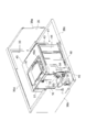
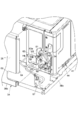
- FIG. 5 is a perspective view of the outdoor unit in a state where the opening of the top plate of the inner housing is opened corresponding to FIG. It is a perspective view which shows typically the structure of the 1st switching valve and the 2nd switching valve. It is a perspective view of the outdoor unit observed from the indoor space side.
- FIG. 1 schematically shows the configuration of an air conditioner 11 according to an embodiment of the present invention.
- the air conditioner 11 includes an indoor unit 12 and an outdoor unit 13.
- the indoor unit 12 is installed, for example, in an indoor space inside a building.
- the indoor unit 12 can be fixed to the wall surface of the indoor space at a height of 2 m or more from the floor surface of the indoor space, for example.
- the indoor unit 12 may be installed in a space corresponding to the indoor space.
- the indoor unit 12 accommodates the indoor heat exchanger 14.
- the outdoor unit 13 accommodates a compressor 15, an outdoor heat exchanger 16, an expansion valve 17, and a four-way valve 18.
- the indoor heat exchanger 14, the compressor 15, the outdoor heat exchanger 16, the expansion valve 17, and the four-way valve 18 form a refrigerating circuit (refrigerant circuit) 19. Further, the outdoor unit 13 is controlled by the first control unit 25, and the indoor unit 12 is controlled by the second control unit 26. The first control unit 25 and the second control unit 26 transmit and receive signals to and from each other.
- the freezing circuit 19 includes a first circulation path 21.
- the first circulation path 21 connects the first port 18a and the second port 18b of the four-way valve 18 to each other.
- a compressor 15 is arranged in the first circulation path 21.
- the suction pipe 15a of the compressor 15 is connected to the first port 18a of the four-way valve 18 via a refrigerant pipe.
- the gas refrigerant is supplied from the first port 18a to the suction pipe 15a of the compressor 15.
- the compressor 15 compresses the low-pressure gas refrigerant to a predetermined pressure.
- the discharge pipe 15b of the compressor 15 is connected to the second port 18b of the four-way valve 18 via a refrigerant pipe.
- the gas refrigerant is supplied from the discharge pipe 15b of the compressor 15 to the second port 18b of the four-way valve 18.
- the refrigerant pipe may be, for example, a copper pipe.
- the freezing circuit 19 further includes a second circulation path 22.
- the second circulation path 22 connects the third port 18c and the fourth port 18d of the four-way valve 18 to each other.
- the outdoor heat exchanger 16, the expansion valve 17, and the indoor heat exchanger 14 are incorporated in the second circulation path 22 in order from the third port 18c side.
- the outdoor heat exchanger 16 exchanges thermal energy between the refrigerant passing through the outdoor heat exchanger 16 and the air in contact with the outdoor heat exchanger 16.
- the indoor heat exchanger 14 exchanges heat energy between the refrigerant passing through the indoor heat exchanger 14 and the air in contact with the indoor heat exchanger 14.
- the second circulation path 22 is connected to the fourth port 18d of the four-way valve 18, is drawn out from the outdoor unit 13, and is connected to the gas pipe 22a extending toward the indoor heat exchanger 14 and the expansion valve 17, and is connected to the outdoor unit 13. Includes a liquid pipe 22b drawn from and extending towards the indoor heat exchanger 14.
- the blower fan 23 is incorporated in the outdoor unit 13.
- the blower fan 23 ventilates the outdoor heat exchanger 16.
- the blower fan 23 generates an air flow according to the rotation of the impeller, for example.
- the airflow passes through the outdoor heat exchanger 16 by the action of the blower fan 23.
- the outdoor air passes through the outdoor heat exchanger 16 and exchanges heat with the refrigerant.
- the heat-exchanged cold or warm airflow is blown out from the outdoor unit 13.
- the flow rate of the airflow passing through is adjusted according to the rotation speed of the impeller.
- the blower fan 24 is incorporated in the indoor unit 12.
- the blower fan 24 ventilates the indoor heat exchanger 14.
- the blower fan 24 generates an air flow according to the rotation of the impeller.
- Indoor air is sucked into the indoor unit 12 by the action of the blower fan 24.
- the indoor air passes through the indoor heat exchanger 14 and exchanges heat with the refrigerant.
- the heat-exchanged cold or warm airflow is blown out from the indoor unit 12.
- the flow rate of the airflow passing through is adjusted according to the rotation speed of the impeller.
- the four-way valve 18 connects the second port 18b and the third port 18c to each other, and connects the first port 18a and the fourth port 18d to each other. Therefore, the high-temperature and high-pressure refrigerant is supplied to the outdoor heat exchanger 16 from the discharge pipe 15b of the compressor 15.
- the refrigerant circulates in order through the outdoor heat exchanger 16, the expansion valve 17, and the indoor heat exchanger 14.
- the outdoor heat exchanger 16 dissipates heat from the refrigerant to the outside air.
- the expansion valve 17 reduces the pressure of the refrigerant to a low pressure.
- the decompressed refrigerant absorbs heat from the surrounding air in the indoor heat exchanger 14. Cold air is generated. The cold air is blown into the indoor space by the action of the blower fan 24.
- the four-way valve 18 connects the second port 18b and the fourth port 18d to each other, and connects the first port 18a and the third port 18c to each other.
- a high-temperature and high-pressure refrigerant is supplied from the compressor 15 to the indoor heat exchanger 14.
- the refrigerant flows through the indoor heat exchanger 14, the expansion valve 17, and the outdoor heat exchanger 16 in this order.
- the indoor heat exchanger 14 dissipates heat from the refrigerant to the surrounding air. Warm air is generated. The warm air is blown into the indoor space by the action of the blower fan 24.
- the expansion valve 17 reduces the pressure of the refrigerant to a low pressure.
- the decompressed refrigerant absorbs heat from the surrounding air by the outdoor heat exchanger 16. After that, the refrigerant returns to the compressor 15.
- the heating operation is carried out for a long time and the temperature of the outdoor heat exchanger 16 becomes below the freezing point, for example, frost may adhere to the outdoor heat exchanger 16. Therefore, in the heating operation, a defrosting operation for removing frost from the outdoor heat exchanger 16 is periodically performed.
- the defrosting operation is carried out in the freezing circuit 19
- the four-way valve 18 connects the second port 18b and the third port 18c to each other and connects the first port 18a and the fourth port 18d to each other, as in the cooling operation. Connect to.
- a high-temperature and high-pressure refrigerant is supplied to the outdoor heat exchanger 16 from the discharge pipe 15b of the compressor 15.
- the refrigerant circulates in order through the outdoor heat exchanger 16, the expansion valve 17, and the indoor heat exchanger 14.
- the outdoor heat exchanger 16 dissipates heat from the refrigerant to the outside air.
- the blower fan 24 is stopped.
- the frost adhering to the outdoor heat exchanger 16 is melted, and this frost is removed from the outdoor heat exchanger 16.
- the water formed by melting the frost in the defrosting operation is used as the defrosting water.
- the defrosting operation since the defrosting operation is periodically performed during the heating operation, the defrosting operation may be included in the heating operation, and the defrosting operation and the heating operation may be collectively referred to as the heating operation.
- the outdoor unit 13 is fitted into an opening 31 formed in a building wall 29 that separates the outdoor space from the indoor space.
- the opening 31 is an outer wall surface of the building 32 and opens into an outdoor space (a space outside the building).
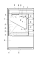
- the outdoor unit 13 includes an outer housing 34 that partitions an internal space that is surrounded by a sound insulating wall and separated from the indoor space while being opened to the outdoor space by the opening 33.
- the opening 31 of the building wall 29 has dimensions determined for PTAC (Packaged Thermal Air Conditioner). The opening 31 penetrates the building wall 29 and connects the indoor space to the outdoor space.
- PTAC Packaged Thermal Air Conditioner
- the outer housing 34 includes a wall body 36 that partitions a storage port 35 that opens toward the indoor space, a front panel 37 that is connected to the wall body 36 and closes the storage port 35, and a wall. It includes a grill 38 that is coupled to the body 36 and installed at the opening 33.
- the wall body 36 has a first side wall (right side wall) 36a extending along a virtual plane orthogonal to the wall surface of the building wall 29 at the right end of the opening 31, and a virtual wall body 36 orthogonal to the wall surface of the building wall 29 at the left end of the opening 31.
- a second side wall (left side wall) 36b extending along a plane, a bottom plate 36c slidably supported with respect to the wall body 36 in parallel with the first side wall 36a and the second side wall 36b, and the first side wall 36a and the second side wall 36a.
- the second side wall 36b faces the first side wall 36a from the left-right direction (horizontal direction parallel to the floor surface in the room at the time of installation) and sandwiches the internal space 39 with the first side wall 36a.
- the first top wall 36d and the second top wall 36e face the bottom plate 36c from the vertical direction (the vertical direction perpendicular to the floor surface in the room at the time of installation, or the direction in which the bottom plate 36c and the bottom plate 48 face each other) with the bottom plate 36c.
- the internal space 39 is sandwiched between the two.
- the grill 38 may be embedded in the outer wall of the building 32, in which case the grill 38 may be omitted from the outer housing 34.
- the first side wall 36a, the second side wall 36b, the bottom plate 36c, the first top wall 36d, the second top wall 36e, and the front panel 37 are each formed as a sound insulation wall. That is, for example, a sound insulating material (sheet) made of urethane resin may be laminated on the inner surfaces of the first side wall 36a, the second side wall 36b, the bottom plate 36c, the first top wall 36d, the second top wall 36e, and the front panel 37.
- the sound insulating material may be sandwiched between metal plates, for example.
- the joint between the first side wall 36a and the bottom plate 36c, the first top wall 36d, and the second top wall 36e can be joined without a gap.
- the joints between the second side wall 36b and the bottom plate 36c, the first top wall 36d, and the second top wall 36e can be similarly joined without gaps.
- the joints between the front panel 37 and the bottom plate 36c, the second top wall 36e, the first side wall 36a, and the second side wall 36b can be similarly joined without gaps.
- a sound insulating material such as urethane resin can also function as a heat insulating material at the same time.
- An inner housing 41 for accommodating the outdoor heat exchanger 16 is arranged in the internal space 39.
- the inner housing 41 is housed between the first side wall 36a and the second side wall 36b.
- the inner housing 41 is supported by the bottom plate 36c from below.
- the inner housing 41 faces the first side wall 36a of the outer housing 34, and the first side plate (right side plate) 43 for partitioning the air outlet 42 and the first side plate 43 in a posture orthogonal to the first side plate 43.
- the second side plate (front plate) 44 which is connected to one end (the end on the indoor space side) and separates the ventilation path in the inner housing 41 from the internal space 39 of the outer housing 34, and as shown in FIG.
- a third side plate 45 which is connected to one end of the second side plate 44 while facing the first side plate 43 to partition a ventilation path from the first side plate 43, and a second side plate 45 as shown in FIG.
- the fourth side plate 47 that is connected to the first side plate 43 and the third side plate 45 while facing the side plate 44, and partitions a suction port 46 that is opened toward the outdoor space.
- the first side plate 43, the second side plate 44, the third side plate 45, and the fourth side plate 47 rise vertically from the bottom plate 48.
- a top plate 49 is coupled to the upper ends of the first side plate 43, the second side plate 44, the third side plate 45, and the fourth side plate 47.
- the ventilation path is partitioned between the bottom plate 48 and the top plate 49.
- the third side plate 45 is partially partitioned with a suction port 51 facing the second side wall 36b of the outer housing 34.
- the outdoor heat exchanger 16 is arranged in the inner housing 41 along the suction port 51 of the third side plate 45 and the suction port 46 of the fourth side plate 47.
- the blower fan 23 is installed in the blower port 42.
- the blower fan 23 may be an axial fan.
- the blower fan 23 has a blade 52 that faces the blower port 42 and rotates about a horizontal axis. During rotation, the blade 52 creates an axial airflow.
- the outside air enters the inner housing 41 from the opening 33 through the suction ports 46 and 51.
- the outside air passes through the outdoor heat exchanger 16. Thermal energy is exchanged between the passing air and the refrigerant in the outdoor heat exchanger 16.
- the air after heat exchange is sent out from the air outlet 42 toward the second side wall 36b.
- a lid Ld that closes the opening 49a that can access the ventilation passage in the inner housing 41 may be attached to the top plate 49.
- a path for accessing the space behind the blower fan 23 and the space inside the outdoor heat exchanger 16 can be secured according to the opening and closing of the lid Ld.
- the refrigerating circuit 19 is incorporated in the gas pipe 22a, connected to the outdoor heat exchanger 16 via the compressor 15, and incorporated in the first switching valve 54 protruding from the third side plate 45 of the inner housing 41 and the liquid pipe 22b. It is connected to the outdoor heat exchanger 16 via the expansion valve 17, and includes a second switching valve 55 that protrudes from the third side plate 45 of the inner housing 41.
- the first switching valve 54 is set in parallel with the introduction pipe 54a extending in the vertical direction from the surface of the third side plate 45 and the introduction pipe 54a branching from the surface of the third side plate 45.
- a screw member 56 that switches the opening and closing of the connection port based on the rotation of the screw about the axis set coaxially with the introduction pipe 54a as the rotation axis is attached to the introduction pipe 54a.
- the screw member 56 is displaced in the axial direction according to the rotation around the horizontal axis Hr.
- the screw member 56 is formed with a hexagon bolt shape that engages with the mouth of the wrench and allows the wrench to be operated around the axis.
- the first connecting pipe 54b extends backward and horizontally from the introduction pipe 54a toward the opening 33 side.
- the first auxiliary refrigerant pipe 58 is coupled to the first connecting pipe 54b according to the tightening of the flare nut 57 around the axis Hx.
- the gas passage of the first auxiliary refrigerant pipe 58 is connected to the connection port of the first connection pipe 54b.
- the first auxiliary refrigerant pipe 58 is pulled out from the outer housing 34 to the indoor space on the indoor space side of the edge of the second side wall 36b on the indoor space side.
- the first auxiliary refrigerant pipe 58 has a first region 58a that is linearly continuous from the first connecting pipe 54b and extends horizontally to the outdoor space side, and a horizontal direction that bends from the first region 58a and moves away from the third side plate 45.
- the second region 58b extending from the second region 58b, the third region 58c bent from the second region 58b and extending horizontally in parallel with the first region 58a toward the storage port 35, and the third side plate bent from the third region 58c.
- a fourth region 58d that extends horizontally away from the 45 and penetrates the second side wall 36b of the outer housing 34, and a fifth region that bends from the fourth region 58d and rises vertically outside the outer housing 34. It has 58e.
- the second connection pipe 54c extends forward and horizontally from the introduction pipe 54a toward the storage port 35 side.
- the first connecting pipe 54b and the second connecting pipe 54c extend from the introduction pipe 54a in a straight line in opposite directions to each other.
- a closing bolt 59 that closes the open end of the suction port is connected to the second connecting pipe 54c based on the rotation of the screw around the axis Hc.
- a vacuum pump is connected to the second connecting pipe 54c when the refrigeration circuit 19 is evacuated.
- the second switching valve 55 forms a connection port having an introduction pipe 55a extending in the vertical direction from the surface of the third side plate 45 and an axis set in parallel with the surface of the third side plate 45 by branching from the introduction pipe 55a. It has a connecting pipe 55b to be connected.
- a screw member 61 that switches the opening and closing of the connection port based on the rotation of the screw around the horizontal axis Hz set coaxially with the introduction pipe 55a is attached to the introduction pipe 55a.
- the screw member 61 is displaced in the axial direction according to the rotation around the horizontal axis Hz.
- the screw member 61 is formed with a hexagon bolt shape that engages with the mouth of the wrench and allows the wrench to be operated around the axis.
- connection pipe 55b extends backward and horizontally from the introduction pipe 55a toward the opening 33 side.
- the second auxiliary refrigerant pipe 63 is coupled to the connecting pipe 55b according to the tightening of the flare nut 62 around the axis Hb.
- the liquid passage of the second auxiliary refrigerant pipe 63 is connected to the connection port of the connection pipe 55b.
- the second auxiliary refrigerant pipe 63 is drawn out from the outer housing 34 to the indoor space on the indoor space side of the edge of the second side wall 36b on the indoor space side.
- the second auxiliary refrigerant pipe 63 extends in the horizontal direction so as to be linearly continuous from the connecting pipe 55b and extend horizontally to the outdoor space side, and bend from the first region 63a and move away from the third side plate 45.
- a fourth region 63d that extends horizontally away from the side plate 45 and penetrates the second side wall 36b of the outer housing 34, and a fifth region that bends from the fourth region 63d and rises vertically outside the outer housing 34. It has a region 63e.
- the edges of the second side wall 36b on the indoor space side are the coupling edge 64 that is vertically partitioned from the floor surface and fitted to the front panel 37, and the first auxiliary refrigerant pipe 58 and the first auxiliary refrigerant pipe 58 that are recessed from the coupling edge 64 toward the outdoor space side. It has an escape edge 65 that receives the entry of the second auxiliary refrigerant pipe 63. The escape edge 65 is closed by the front panel 37. As shown in FIG. 9, the flank 65 is hardened with the resin material 66. The resin material 66 is formed in the recess of the relief edge 65 and fills the space existing around the first auxiliary refrigerant pipe 58 and the second auxiliary refrigerant pipe 63. As shown in FIG.
- a bracket 67 that supports the fourth region 58d of the first auxiliary refrigerant pipe 58 and the fourth region 63d of the second auxiliary refrigerant pipe 63 is attached to the bottom plate 36c of the outer housing 34 from below. Be done.
- the bracket 67 positions the first auxiliary refrigerant pipe 58 and the second auxiliary refrigerant pipe 63 in the recess of the relief edge 65.
- the lower end of the first side wall 36a is bent inward from the plate material of the first side wall 36a and linearly formed from the storage port 35 to the opening port 33.
- the extending guide plate 71 is connected.
- One side edge (right edge) of the bottom plate 36c is slidably received by the guide plate 71 in parallel with the first side wall 36a.
- a guide plate that is bent inward from the plate material of the second side wall 36b and extends linearly from the storage opening 35 to the opening port 33 is connected to the lower end of the second side wall 36b.
- the other side edge (left edge) of the bottom plate 36c is slidably received in parallel with the second side wall 36b.
- a vertical wall 72 formed by bending upward from the plate material of the bottom plate 36c is connected to the front end (indoor space side end) of the bottom plate 36c. At the left and right ends of the vertical wall 72, overlapping pieces 73 extending outward in the left-right direction are formed.
- a restricting piece 74 extending inward is formed at the front end of the first side wall 36a above the guide plate 71.
- the regulation piece 74 is bent and molded inward from the plate material of the first side wall 36a.
- the outdoor unit 13 is combined with the indoor unit 12 to provide a separate type air conditioner 11.
- the outdoor housing 34 When the outer housing 34 is fitted into the opening 31 of the building wall 29, the internal space 39 of the outer housing 34 is separated from the interior space by a sound insulation wall. The flow of air from the interior space 39 toward the interior space can be blocked.
- the outdoor unit 13 exchanges heat between the outside air entering the internal space 39 and the refrigerant. The efficiency of heat exchange can be ensured well.
- the noise in the outdoor space is blocked by the sound insulation wall. The ingress of noise can be satisfactorily prevented. The quietness of the indoor space can be ensured well.
- the opening 31 of the building wall 29 has dimensions determined for PTAC.
- PTAC PTAC
- the outer housing 34 When installing the air conditioner 11, the outer housing 34 is assembled. The first side wall 36a and the second side wall 36b are assembled to the first top wall 36d. Subsequently, the assembly of the first side wall 36a, the second side wall 36b, and the first top wall 36d is installed in the opening 31 of the building wall 29 prior to the assembly of the bottom plate 36c. The assembly may be inserted into the opening 31 of the building wall 29 from the interior space. Here, the installation position of the second top wall 36e can be maintained in the indoor space.
- the bottom plate 36c is connected to the first side wall 36a and the second side wall 36b.
- the bottom plate 36c is installed on the guide plate 71 of the first side wall 36a and the guide plate of the second side wall 36b. At this time, the bottom plate 36c can be pulled out to the indoor space side to the maximum extent.
- the first switching valve 54 and the second switching valve 55 are located on the indoor space side of the storage port 35 of the outer housing 34. Therefore, the movable range of the bottom plate 36c may be adjusted based on the positional relationship between the first switching valve 54 and the second switching valve 55 and the coupling edge 64 of the second side wall 36b.
- the first auxiliary refrigerant pipe 58 and the second auxiliary refrigerant pipe 63 are coupled to the connection ports of the first switching valve 54 and the second switching valve 55, respectively.
- the first auxiliary refrigerant pipe 58 can be supported by the first connecting pipe 54b and the bracket 67.
- the second auxiliary refrigerant pipe 63 can be supported by the connecting pipe 55b and the bracket 67. In this way, the first auxiliary refrigerant pipe 58 and the second auxiliary refrigerant pipe 63 can be positioned at fixed positions.
- the flare nut 57 of the first auxiliary refrigerant pipe 58 is tightened with a wrench around the axis Hx. A liquidtight bond can be established.
- the flare nut 62 of the second auxiliary refrigerant pipe 63 is tightened with a wrench around the axis Hb. A liquidtight bond can be established.
- the flare nuts 57 and 62 are located on the indoor space side of the connecting edge 64 of the second side wall 36b, the first auxiliary refrigerant pipe 58 or the second auxiliary refrigerant pipe 63 and the second side wall of the outer housing 34 are located. Interference with 36b can be avoided. In this way, since the work of the wrench is performed prior to the storage in the outer housing 34, a sufficient work space can be secured. Efficient work can be realized in connecting the first auxiliary refrigerant pipe 58 and the second auxiliary refrigerant pipe 63.
- the outer housing 34 is provided with a bottom plate 36c that is slidably supported with respect to the wall body 36 in parallel with the second side wall 36b and supports the inner housing 41 from below.
- the bottom plate 36c can slide relative to the wall body 36 of the outer housing 34. Therefore, the storage work of the inner housing 41 can be easily realized. Efficient work can be achieved.
- the inner housing 41 is housed in the internal space 39 of the outer housing 34. Will be done.
- the stacking piece 73 of the bottom plate 36c is superposed on the regulation piece 74.
- the overlapping piece of the bottom plate 36c is overlapped with the regulation piece.
- the fluid of the resin material 66 is applied around the first auxiliary refrigerant pipe 58 and the second auxiliary refrigerant pipe 63. Waiting for the resin material 66 to solidify, the escape edge 65 is closed. The sound insulation of the outer housing 34 can be ensured. Since the bracket 67 functions as an aggregate of the fluid when the resin material 66 is applied, the resin material 66 can be satisfactorily held in the escape edge 65 until solidification.
- the connection ports of the first switching valve 54 and the second switching valve 55 are opened.
- the refrigerant can flow in the refrigerant pipe.
- the screw members 56 and 61 are driven around the horizontal axis Hr and Hz.
- a sufficient space is secured between the second side wall 36b and the third side plate 45 of the inner housing 41.
- the work of driving the screw members 56 and 61 around the horizontal axis Hr and Hz with a wrench can be satisfactorily realized.
- the second top wall 36e can be installed after the inner housing 41 is housed in the internal space 39 of the outer housing 34.
- the second top wall 36e is tightly coupled to the upper end of the first side wall 36a and the upper end of the second side wall 36b.
- a urethane sound insulating material can be sandwiched in the bonding.
- the first top wall 36d and the second top wall 36e they are in contact with each other without a gap. In this way, the first top wall 36d is embedded in the building wall 29 to form a sound insulation wall in the building wall 29.
- the second top wall 36e is arranged in the interior space, a route to access the internal space 39 can be secured according to the opening and closing of the second top wall 36e. Good maintenance work can be realized even after the installation of the air conditioner 11.
- the storage port 35 of the outer housing 34 is closed by the front panel 37. Since a relief edge 65 is formed on the second side wall 36b of the outer housing 34 when arranging the first auxiliary refrigerant pipe 58 and the second auxiliary refrigerant pipe 63, the first auxiliary refrigerant pipe 58 and the second auxiliary refrigerant pipe 63 In the arrangement, the protrusion of the front panel 37 on the indoor space side can be avoided. The protrusion of the outdoor unit 13 from the building wall 29 can be suppressed as much as possible. In addition, the design of the front panel 37 can be well maintained.
- the first auxiliary refrigerant pipe 58 and the second auxiliary refrigerant pipe 63 may be pulled out from the front panel 37.
- the outer housing 34 can be completely housed in the opening 31 of the building wall 29.
- the wall surface of the building wall 29 and the front panel 37 can be set flush with each other. In this way, the outdoor unit 13 can be used for building walls 29 having various wall thicknesses.
- the defrosting operation is switched to the heating operation, cold outside air (for example, outside air below the freezing point) is sucked into the inner housing 41 again from the opening 33.
- cold outside air for example, outside air below the freezing point
- the defrost water accumulated in the bottom plate 36c of the outer housing 34 may come into contact with the outside air and the defrost water may freeze. be. If the defrost water is repeatedly frozen, the holes provided in the bottom plate 48 may be blocked by ice, and the defrost water may not be drained to the outer housing 34.
- a heater 80 for preventing freezing of the defrosted water may be arranged in the outer housing 34.
- the heater 80 is, for example, a resistance heating type heater.
- the heater 80 generates Joule heat by energizing an electric current inside the heater 80. It also heats the members around the heater.
- the heater 80 is arranged, for example, between the inner housing 41 and the outer housing 34. This makes it possible to prevent the defrost water from freezing between the inner housing 41 and the outer housing 34.
- a defrost water tray (hereinafter, also referred to as a drain pan 36s) is provided between the inner housing 41 and the outer housing 34 (described later).
- the drain pan 36s temporarily stores the defrosted water in which the frost adhering to the outdoor heat exchanger 16 of the outdoor unit 13 is dissolved.
- the drain pan 36s includes a bottom surface 36s1 and a side surface 36s2 erected from the outer periphery of the bottom surface 36s1.
- FIG. 15 shows a plane in which the outer housing 34 is viewed from above when the inner housing 41 is removed.
- the outer shape of the outdoor heat exchanger 16 is shown by a broken line.
- the outdoor heat exchanger 16 has an L shape as shown in FIG.
- the heater 80 has a loop shape and is fixed to the bottom surface 36s1 by the fixture 81.
- the heater 80 comes into contact with the bottom surface 36s1.
- a conductive wire (not shown) for supplying electric power to the heater 80 is connected to the end 80p and the end 80n, which are the ends of the heater 80.
- the power supply to the heater 80 is controlled by the first control unit 25.
- the outer housing 34 is provided with a drain pan 36s in the area defined by the broken line P1.
- the inner housing 41 is arranged above the area defined by the broken line P1.
- the frost adhering to the outdoor heat exchanger 16 is melted, and a certain amount of the defrosted water drained from the inner housing 41 can be stored in the drain pan 36s.
- at least a part of the heater 80 is housed in the drain pan 36s. As a result, the defrost water stored in the drain pan 36s can be prevented from being frozen again by the outside air by the heat generated by the heater 80.
- the bottom surface 36s1 and the bottom plate 36c are provided with a drain port 36h for draining defrost water to the outside of the outer housing 34.
- the inner housing 41 or the outer housing 34 is provided with a pump (not shown) such as a drain pump that discharges defrosted water to the outside of the outer housing 34 via the drain port 36h.
- a pump such as a drain pump that discharges defrosted water to the outside of the outer housing 34 via the drain port 36h.
- the pump can be operated without being linked to the operation of the air conditioner 11. As a result, even if rainwater accumulates in the drain pan 36s due to a storm or the like while the operation of the air conditioner 11 is stopped, the float switch mounted on the pump operates and drains the air conditioner 11.
- the plurality of holes 48h shown by the broken lines in FIG. 15 indicate the outer shapes of the plurality of holes provided in the bottom plate 48 of the inner housing 41 facing the bottom surface 36s1 of the drain pan 36s in the vertical direction.
- the plurality of holes 48h are located below the outdoor heat exchanger 16.
- the defrost water that has flowed down from the outdoor heat exchanger 16 due to the defrost operation falls from the inner housing 41 to the bottom surface 36s1 of the drain pan 36s through the plurality of holes 48h.
- the plurality of holes 48h are arranged side by side according to the outer shape of the L-shaped outdoor heat exchanger 16.
- a part of the heater 80 is housed in the drain pan 36s along the direction in which the plurality of holes 48h are lined up in the outer housing 34. Further, a portion of the heater 80 other than the portion thereof is housed in the drain pan 36s so as to be adjacent to the drain port 36h in the outer housing 34.
- the heater 80 has a straight portion extending linearly and a plurality of bending portions that bend at an acute angle or an obtuse angle. The straight portion is arranged on the bottom surface 36s1 so as to be aligned with the holes 48h. Then, one of the bent portions is arranged on the bottom surface 36s1 so as to be along the edge of the drain port 36h.
- the defrosted water is guided to the drain port 36h by the heater 80. Then, the defrosted water can be reliably drained to the outside of the outer housing 34 through the plurality of holes 48h and the drainage port 36h. Since the defrost water is guided to the drain port 36h by the heater 80, it is difficult for the defrost water to be stored in a place away from the heater 80. Therefore, in order to prevent the defrost water from freezing, the heater 80 does not have to be heated to a temperature high enough to heat the entire bottom surface 36s1. As a result, it is possible to suppress an increase in the electric power applied to the heater 80.
- the first control unit 25 that controls the heater 80 is provided in, for example, the inner housing 41.
- the first control unit 25 energizes the heater 80 when the first control unit 25 receives a signal indicating a heating operation (heating operation including defrosting operation) from the second control unit 26 provided in the indoor unit 12. ..
- a heating operation heating operation including defrosting operation
- the first control unit 25 sets the heating operation mode from the second control unit 26.
- the heater 80 is energized.
- the heater 80 can be energized in synchronization with the heating operation.
- the heater 80 may be controlled to start energization according to the outside air temperature in the heating operation by the control of the first control unit 25, and the energization is started when the outside air temperature becomes, for example, 2 ° C. or lower. You may.
- the outside air temperature is detected from the suction air by the outside air temperature thermistor 86.
- the heater 80 is set so that the heater surface temperature is higher than 0 ° C. even when the outside air temperature is, for example, -15 ° C. By doing so, it is possible to prevent the defrost water from freezing even when the outside air temperature drops extremely.
- the first top wall 36d On the inner surfaces of the first side wall 36a, the second side wall 36b, the bottom plate 36c (excluding the portion where the drain pan 36s is provided), the first top wall 36d, the second top wall 36e, and the front panel 37, respectively. Sound insulation material is placed. Further, in this modification, as shown in FIG. 16, a sound insulating material 85 is provided on the outside of the outer housing 34 corresponding to the location where the drain pan 36s is arranged. For example, the sound insulating material 85 is arranged under the bottom plate 36c. As the material of the sound insulating material 85, foamed polyethylene or the like having excellent sound insulation, heat insulating properties, flexibility and workability is applied.
- the sound insulating material 85 By arranging the sound insulating material 85 under the bottom plate 36c, the sound of the compressor 15 and the sound of drainage of the defrosting water are emitted from the inner housing 41 or the outer housing 34 from the drain pan 36s in which the sound insulating material is not arranged on the inner surface. Leakage into the room is more reliably suppressed. Further, even if cold outside air is sucked into the inner housing 41 from the opening 33, the temperature of the outside air is insulated by the heat insulating property of the sound insulating material 85, and the room temperature is less affected by the outside air temperature.
- the sound insulation material 85 is. At least, it may be provided on the outside of the outer housing 34 corresponding to the location where the drain pan 36s is arranged.
Landscapes
- Engineering & Computer Science (AREA)
- Chemical & Material Sciences (AREA)
- Combustion & Propulsion (AREA)
- Mechanical Engineering (AREA)
- General Engineering & Computer Science (AREA)
- Other Air-Conditioning Systems (AREA)
- Air Conditioning Control Device (AREA)
Abstract
【課題】室外空間と室内空間を仕切る建造物壁に形成される開口に嵌め込まれる筐体を備え、室内空間に向かって良好に騒音の進入を防止することができる空気調和機を提供する。 【解決手段】空気調和機は、室内空間の壁面に固定されて、室内熱交換器を収容する室内機12と、室内熱交換器を含む冷媒回路に接続される室外熱交換器を収容する室外機13とを備える。室外機13は、室外空間と室内空間を仕切る建造物壁に形成される開口に嵌め込まれて、室外空間に開放されながら遮音壁で囲まれて室内空間から隔てられる内部空間39を区画する外側筐体34と、内部空間39内に配置されて、室外熱交換器を収容する内側筐体41とを備える。
Description
本発明は、室内空間の壁面に固定されて、室内熱交換器を収容する室内機と、室内熱交換器を含む冷媒回路に接続される室外熱交換器を収容する室外機とを備える空気調和機に関する。
特許文献1および特許文献2には、いわゆるPTAC(Packaged Terminal Air Conditioner)と呼ばれる空気調和機であって、室外空間と室内空間を仕切る壁に形成される開口に嵌め込まれて、室内熱交換器および室外熱交換器を含む冷媒回路を収容する筐体を備える空気調和機が開示される。筐体内は、室外空間に開放される室外側空間と、室内空間に開放される室内側空間とに隔壁(バルクヘッド)で仕切られる。隔壁により筐体内の室外側空間と室内側空間との間では空気の移動は回避されることができる。こうして空調は実現される。
特許文献1では底板トレイ上に隔壁は設置される。底板トレイは筐体の底板に沿って筐体内に配置される。内部部品の配置の邪魔にならないよう、隔壁はできるだけ薄くすることが求められる。したがって、筐体の室外熱交換器側の空気と室内熱交換器側の空気とは隔壁を介して熱交換されることから、隔壁で十分な断熱をすることはできない。また、隔壁はできるだけ薄くすることが求められることから、遮音構造を取ることができない。室外空間の騒音は室外側空間から室内側空間に漏れ入ってしまう。
特許文献2では、室内側熱交換器で生じたドレン水を室外側に導くドレンパン上に、隔壁は配置される。ドレンパンと隔壁との間には間隙が形成される。したがって、室外空間の騒音は室外側空間から室内側空間に漏れ入ってしまう。
本発明は、室外空間と室内空間を仕切る建造物壁に形成される開口に嵌め込まれる筐体を備え、室内空間に向かって良好に騒音の進入を防止することができる空気調和機を提供することを目的とする。
本発明の一側面によれば、室内空間の壁面に固定されて、室内熱交換器を収容する室内機と、前記室内熱交換器を含む冷媒回路に接続される室外熱交換器を収容する室外機とを備え、前記室外機は、室外空間と室内空間を仕切る建造物壁に形成される開口に嵌め込まれて、前記室外空間に開放されながら遮音壁で囲まれて前記室内空間から隔てられる内部空間を区画する外側筐体と、前記内部空間内に配置されて、前記室外熱交換器を収容する内側筐体とを備える空気調和機が提供される。
室外機は室内機に組み合わせられてセパレート型の空気調和機を提供する。外側筐体が建造物壁の開口に嵌め込まれると、外側筐体の内部空間は遮音壁で室内空間から隔てられる。内部空間から室内空間に向かって空気の流通は阻止されることができる。内部空間に進入する外気と冷媒との間で室外機は熱交換を実施する。熱交換の効率は良好に確保されることができる。ここで、室外空間の騒音は遮音壁で遮られる。良好に騒音の進入は防止されることができる。室内空間の静寂性は良好に確保されることができる。
前記外側筐体は、前記建造物壁の壁面に直交する仮想平面に沿って広がる側壁を含んで、前記室内空間に向かって開口する収納口を区画する壁体と、前記壁体に結合されて前記収納口を塞ぐフロントパネルとを有してもよい。前記内側筐体は、前記室外空間に向かって開放される吸込口と、前記側壁に向かって熱交換後の空気を送り出す送風口とを有してもよい。
建造物壁の開口はPTAC向けに決められた寸法を有する。ここでは、建造物壁の開口には室外機のみが配置されればよいことから、送風口と外側筐体の側壁との間には大きな空間が確保されることができる。こうして送風口から熱交換後の空気は効率的に室外空間に向かって排出されることができる。室外熱交換器を通過する空気の流量は促進されることができる。室外機では熱交換の効率は高められることができる。
前記外側筐体は、前記壁体に含まれて、前記側壁との間に前記内側筐体を収容する第2側壁を備えてもよい。このとき、前記冷媒回路は、前記室外熱交換器に接続されて、前記内側筐体で前記第2側壁に向き合わせられる側板から突出し、前記側板の板面に垂直に設定される軸線を回転軸とするねじの回転に基づき接続口の開閉を切り替える切り換えバルブを備えてもよい。
空気調和機の設置時、切り換えバルブの接続口に冷媒管が接続された後に切り換えバルブの接続口は開弁される。こうして冷媒管内に冷媒は流通することができる。切り換えバルブの開弁にあたって軸線を回転軸としてねじは回される。ここでは、建造物壁の開口には室外機のみが配置されればよいことから、第2側壁と内側筐体の側板との間には十分な空間が確保されることができる。外側筐体の内部空間では、例えばレンチで軸線回りにねじを駆動する作業は良好に実現されることができる。
前記外側筐体は、前記建造物壁の壁面に直交する仮想平面に沿って広がる側壁を含んで、前記室内空間に向かって開口する収納口を区画する壁体と、前記壁体に結合されて前記収納口を塞ぐフロントパネルとを有してもよい。このとき、前記冷媒回路は、前記室外熱交換器に接続されて、前記内側筐体で前記側壁に向き合わせられる側板から突出し、前記側板の板面に並列に設定される軸線を有する接続口を形成する切り換えバルブと、前記軸線を回転軸とするフレアナットの締め付けに応じて前記接続口に結合され、前記側壁の前記室内空間側の縁よりも前記室内空間側で前記外側筐体から前記室内空間に引き出される補助冷媒管とを有してもよい。
空気調和機の設置にあたって切り換えバルブの接続口には補助冷媒管が結合される。軸線回りにフレアナットはレンチで締め付けられる。液密に結合は確立されることができる。補助冷媒管の結合後、収納口から外側筐体内に内側筐体は収納される。このとき、補助冷媒管と外側筐体の側壁との干渉は回避されることができる。こうして外側筐体への収納に先立ってレンチの作業は実施されることから、十分な作業スペースは確保されることができる。補助冷媒管の結合にあたって効率的な作業は実現されることができる。
前記外側筐体は、前記側壁に並行に前記壁体に対してスライド自在に支持されて、下方から前記内側筐体を支持する底板を備えてもよい。内側筐体の収納にあたって底板は外側筐体の壁体に対して相対的にスライドすることができる。したがって、内側筐体の収納作業は容易に実現されることができる。効率的な作業は実現されることができる。
前記側壁の室内空間側の縁は、室内空間の床面に対して垂直方向に仕切られてフロントパネルに合わせ込まれる結合縁と、前記結合縁から室外空間側に窪んで前記補助冷媒管の進入を受け入れる逃げ縁とを有してもよい。外側筐体の側壁には補助冷媒管の配置にあたって逃げ縁が形成されるので、補助冷媒管の配置にあたって室内空間側にフロントパネルの出っ張りは回避されることができる。建造物壁から室外機の出っ張りはできる限り抑制されることができる。加えて、フロントパネルの意匠性は良好に維持されることができる。
前記外側筐体は、前記建造物壁の壁面に直交する仮想平面に沿って広がる左右の側壁と、前記側壁の室外空間側端から室内空間側に延びて、左右の前記側壁で挟まれる前記内部空間を上方から塞ぐ第1天壁と、前記第1天壁から室内空間側に前記側壁の室内空間側端まで延びて、開閉可能に前記内部空間を上方から塞ぐ第2天壁とを備えてもよい。第1天壁は建造物壁に埋め込まれて建造物壁内に遮音壁を形成する。第2天壁が室内空間内に配置されれば、第2天壁の開閉に応じて内部空間にアクセスする経路は確保されることができる。空気調和機の設置後であっても良好なメンテナンス作業は実現されることができる。
前記外側筐体と前記内側筐体との間に、ヒータが配置されてもよい。外側筐体と前記内側筐体との間に、ヒータが配置されることで、外側筐体におけるに除霜水の凍結が防止される。また、この配置によって、暖房運転で霜(氷)が成長する内側筐体の床板または外側筐体の底板が効率よくヒータによって暖められ、ヒータに投入する電力の増大が抑制され、ヒータ電力の無駄な消費が抑えられる。
前記外側筐体は、前記室外熱交換器に付着した霜が溶解した除霜水を貯留するドレンパンと、前記除霜水を前記外側筐体の外側に排出するポンプとを有してもよい。ドレンパンに溜まった除霜水はポンプによって排水され、ドレンパンから除霜水が漏れることが回避される。
前記ヒータの少なくとも一部は、前記ドレンパンに収容されてもよい。ドレンパンで凍った霜(氷)は、ヒータによって効率よく溶かされる。
前記内側筐体には、前記ヒータを制御する第1制御部が設けられ、前記第1制御部は、前記室内機に設けられた第2制御部から除霜運転を含む暖房運転を示す信号を前記第2制御部が受信した場合に前記ヒータを通電させてもよい。ヒータを通電させる制御を空気調和機に具備された第1制御部によって行うことで、暖房運転と同期させてヒータを通電させることができる。
前記ヒータは、前記第1制御部によって、外気温に応じて通電が開始するように制御されてもよい。この温度範囲に設定されることで、除霜水の凍結が防止され、無用な電力の消費が抑えられる。
少なくとも前記ヒータが配置された箇所に対応する前記外側筐体の外側に前記遮音材をさらに具備してもよい。遮音材を設けることで、圧縮機の音、除霜水の排水される音が内側筐体または外側筐体から漏れることが抑制される。また、冷たい外気が内側筐体内に吸引されても、遮音材の断熱性によって外気の温度が断熱され、室内温度が外気温によって影響を受けにくくなる。
前記内側筐体の前記底板には、前記除霜水を前記ドレンパンに落下させる複数の孔が設けられ、前記ヒータの一部は、前記複数の孔が並ぶ方向に沿うように前記ドレンパンに収容されてもよい。前記ドレンパンには、前記除霜水を前記外側筐体の外側に排水する排水口が設けられ、前記ヒータの前記一部とは別の部分は、前記外側筐体において前記排水口に隣接するように前記ドレンパンに収容されてもよい。このような配置によって、複数の孔及び排水口、または複数の孔及び排水口のそれぞれの周辺での除霜水の凍結が回避されて、除霜水を確実に複数の孔及び排水口を介して外側筐体の外に排水することができる。
以上のように開示の空気調和機によれば、室外空間と室内空間を仕切る建造物壁に形成される開口に嵌め込まれる筐体を備えながら、室内空間に向かって良好に騒音の進入を防止することができる。
図1は本発明の一実施形態に係る空気調和機11の構成を概略的に示す。空気調和機11は室内機12および室外機13を備える。室内機12は例えば建造物内の室内空間に設置される。室内機12は、例えば室内空間の床面から2m以上の高さで室内空間の壁面に固定されることができる。その他、室内機12は室内空間に相当する空間に設置されればよい。室内機12には室内熱交換器14が収容される。室外機13には圧縮機15、室外熱交換器16、膨張弁17および四方弁18が収容される。室内熱交換器14、圧縮機15、室外熱交換器16、膨張弁17および四方弁18は冷凍回路(冷媒回路)19を形成する。また、室外機13は、第1制御部25によって制御され、室内機12は、第2制御部26によって制御される。第1制御部25と第2制御部26とは、相互に信号を送受信する。
冷凍回路19は第1循環経路21を備える。第1循環経路21は四方弁18の第1口18aおよび第2口18bを相互に結ぶ。第1循環経路21には圧縮機15が配置される。圧縮機15の吸入管15aは四方弁18の第1口18aに冷媒配管を介して接続される。第1口18aからガス冷媒は圧縮機15の吸入管15aに供給される。圧縮機15は低圧のガス冷媒を所定の圧力まで圧縮する。圧縮機15の吐出管15bは四方弁18の第2口18bに冷媒配管を介して接続される。圧縮機15の吐出管15bからガス冷媒は四方弁18の第2口18bに供給される。冷媒配管は例えば銅管であればよい。
冷凍回路19は第2循環経路22をさらに備える。第2循環経路22は四方弁18の第3口18cおよび第4口18dを相互に結ぶ。第2循環経路22には、第3口18c側から順番に室外熱交換器16、膨張弁17および室内熱交換器14が組み込まれる。室外熱交換器16は、室外熱交換器16を通過する冷媒と室外熱交換器16に接触する空気との間で熱エネルギーを交換する。室内熱交換器14は、室内熱交換器14を通過する冷媒と室内熱交換器14に接触する空気との間で熱エネルギーを交換する。第2循環経路22は、四方弁18の第4口18dに接続されて室外機13から引き出され、室内熱交換器14に向かって延びるガス管22aと、膨張弁17に接続されて室外機13から引き出され、室内熱交換器14に向かって延びる液管22bとを含む。
室外機13には送風ファン23が組み込まれる。送風ファン23は室外熱交換器16に通風する。送風ファン23は例えば羽根車の回転に応じて気流を生成する。送風ファン23の働きで気流は室外熱交換器16を通り抜ける。室外の空気は室外熱交換器16を通り抜け冷媒と熱交換する。熱交換された冷気または暖気の気流は室外機13から吹き出される。通り抜ける気流の流量は羽根車の回転数に応じて調整される。
室内機12には送風ファン24が組み込まれる。送風ファン24は室内熱交換器14に通風する。送風ファン24は羽根車の回転に応じて気流を生成する。送風ファン24の働きで室内機12には室内空気が吸い込まれる。室内空気は室内熱交換器14を通り抜け冷媒と熱交換する。熱交換された冷気または暖気の気流は室内機12から吹き出される。通り抜ける気流の流量は羽根車の回転数に応じて調整される。
冷凍回路19で冷房運転が実施される場合には、四方弁18は第2口18bおよび第3口18cを相互に接続し第1口18aおよび第4口18dを相互に接続する。したがって、圧縮機15の吐出管15bから高温高圧の冷媒が室外熱交換器16に供給される。冷媒は室外熱交換器16、膨張弁17および室内熱交換器14を順番に流通する。室外熱交換器16では冷媒から外気に放熱する。膨張弁17で冷媒は低圧まで減圧される。減圧された冷媒は室内熱交換器14で周囲の空気から吸熱する。冷気が生成される。冷気は送風ファン24の働きで室内空間に吹き出される。
冷凍回路19で暖房運転が実施される場合には、四方弁18は第2口18bおよび第4口18dを相互に接続し第1口18aおよび第3口18cを相互に接続する。圧縮機15から高温高圧の冷媒が室内熱交換器14に供給される。冷媒は室内熱交換器14、膨張弁17および室外熱交換器16を順番に流通する。室内熱交換器14では冷媒から周囲の空気に放熱する。暖気が生成される。暖気は送風ファン24の働きで室内空間に吹き出される。膨張弁17で冷媒は低圧まで減圧される。減圧された冷媒は室外熱交換器16で周囲の空気から吸熱する。その後、冷媒は圧縮機15に戻る。
暖房運転を長く実施し、室外熱交換器16の温度が氷点下になると、例えば、室外熱交換器16に霜が付着する場合がある。従って、暖房運転では室外熱交換器16から霜を取り除く除霜運転が定期的に実施される。冷凍回路19で除霜運転が実施される場合には、冷房運転と同様に、四方弁18は第2口18bおよび第3口18cを相互に接続し第1口18aおよび第4口18dを相互に接続する。圧縮機15の吐出管15bから高温高圧の冷媒が室外熱交換器16に供給される。冷媒は室外熱交換器16、膨張弁17および室内熱交換器14を順番に流通する。室外熱交換器16では冷媒から外気に放熱する。送風ファン24は停止される。これにより、室外熱交換器16に付着した霜が融解し、この霜が室外熱交換器16から除霜される。なお、除霜運転で霜が融解して形成された水を除霜水とする。また、除霜運転は、暖房運転中に定期的に実施されることから、除霜運転を暖房運転に含ませ、除霜運転と暖房運転とをまとめて暖房運転としてもよい。
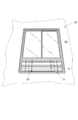
図2および図3に示されるように、室外機13は、室外空間と室内空間を仕切る建造物壁29に形成される開口31に嵌め込まれる。開口31は建造物32の外壁面で室外空間(建造物外の空間)に開口する。ここでは、室外機13は、開放口33で室外空間に開放されながら遮音壁で囲まれて室内空間から隔てられる内部空間を区画する外側筐体34を備える。建造物壁29の開口31はPTAC(Packaged Terminal Air Conditioner)向けに決められた寸法を有する。開口31は、建造物壁29を貫通し、室外空間に室内空間を接続する。
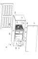
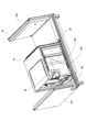
外側筐体34は、図4に示されるように、室内空間に向かって開口する収納口35を区画する壁体36と、壁体36に結合されて収納口35を塞ぐフロントパネル37と、壁体36に結合されて開放口33に設置されるグリル38とを備える。壁体36は、開口31の右端で建造物壁29の壁面に直交する仮想平面に沿って広がる第1側壁(右側壁)36aと、開口31の左端で建造物壁29の壁面に直交する仮想平面に沿って広がる第2側壁(左側壁)36bと、第1側壁36aおよび第2側壁36bに並行に壁体36に対してスライド自在に支持される底板36cと、第1側壁36aおよび第2側壁36bの室外空間側端から室内空間側に延びて、第1側壁36aおよび第2側壁36bの上端に結合されて第1側壁36aおよび第2側壁36bで挟まれる内部空間39を上方から塞ぐ第1天壁36dと、第1天壁36dから室内空間側に第1側壁36aおよび第2側壁36bの室内空間側端まで延びて、開閉可能に内部空間39を上方から塞ぐ第2天壁36eとを有する。第2側壁36bは第1側壁36aに左右方向(設置時に室内の床面と平行となる水平方向)から向き合って第1側壁36aとの間に内部空間39を挟む。第1天壁36dおよび第2天壁36eは底板36cに上下方向(設置時に室内の床面と垂直となる垂直方向、または、底板36cと底板48とが対向する方向)から向き合って底板36cとの間に内部空間39を挟む。グリル38は、建造物32の外壁に埋め込まれてもよく、その場合には外側筐体34からグリル38は省略されてもよい。
第1側壁36a、第2側壁36b、底板36c、第1天壁36d、第2天壁36eおよびフロントパネル37はそれぞれ遮音壁として形成される。すなわち、第1側壁36a、第2側壁36b、底板36c、第1天壁36d、第2天壁36eおよびフロントパネル37の内面には例えばウレタン樹脂製の遮音材(シート)が重ねられればよい。遮音材は例えば金属板同士の間に挟まれてもよい。第1側壁36aと、底板36cや第1天壁36d、第2天壁36eとの合わせ目は隙間なく結合されることができる。第2側壁36bと、底板36cや第1天壁36d、第2天壁36eとの合わせ目は同様に隙間なく結合されることができる。フロントパネル37と、底板36cや第2天壁36e、第1側壁36a、第2側壁36bとの合わせ目は同様に隙間なく結合されることができる。ウレタン樹脂といった遮音材は同時に断熱材としても機能することができる。
内部空間39内には室外熱交換器16を収容する内側筐体41が配置される。内側筐体41は第1側壁36aおよび第2側壁36bの間に収容される。内側筐体41は下方から底板36cに支持される。
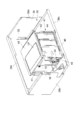
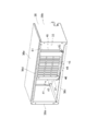
内側筐体41は、外側筐体34の第1側壁36aに向き合わせられて、送風口42を区画する第1側板(右側板)43と、第1側板43に直交する姿勢で第1側板43の一端(室内空間側端)に連結されて、外側筐体34の内部空間39から内側筐体41内の通風路を仕切る第2側板(前板)44と、図5にしめされるように、第1側板43に向き合わせられながら第2側板44の一端に連結されて、第1側板43との間に通風路を区画する第3側板45と、図6に示されるように、第2側板44に向き合わせられながら第1側板43および第3側板45に連結されて、室外空間に向かって開放される吸込口46を区画する第4側板47とを有する。第1側板43、第2側板44、第3側板45および第4側板47は底板48から垂直方向に立ち上がる。図5に示されるように、第1側板43、第2側板44、第3側板45および第4側板47の上端には天板49が結合される。底板48と天板49との間に通風路は区画される。ここでは、第3側板45に、部分的に、外側筐体34の第2側壁36bに向き合わせられる吸込口51が区画される。
図5および図6に示されるように、内側筐体41内では第3側板45の吸込口51および第4側板47の吸込口46に沿って室外熱交換器16が配置される。図4に示されるように、送風口42に送風ファン23は設置される。送風ファン23は、軸流ファンであればよい。送風ファン23は、送風口42に向き合って、水平な軸線回りで回転するブレード52を有する。回転時にブレード52は軸方向に気流を生み出す。外気は開放口33から吸込口46、51を通って内側筐体41内に進入する。外気は室外熱交換器16を通過する。通過する空気と室外熱交換器16内の冷媒との間で熱エネルギーは交換される。送風口42から第2側壁36bに向かって熱交換後の空気は送り出される。ここで、天板49には、図5および図7に示されるように、内側筐体41内の通風路にアクセス可能な開口49aを塞ぐ蓋体Ldが取り付けられてもよい。蓋体Ldの開閉に応じて送風ファン23の背後や室外熱交換器16内側の空間にアクセスする経路は確保されることができる。
冷凍回路19は、ガス管22aに組み込まれて圧縮機15経由で室外熱交換器16に接続され、内側筐体41の第3側板45から突出する第1切り換えバルブ54と、液管22bに組み込まれて膨張弁17経由で室外熱交換器16に接続され、内側筐体41の第3側板45から突出する第2切り換えバルブ55とを備える。図8に示されるように、第1切り換えバルブ54は、第3側板45の表面から垂直方向に延びる導入管54aと、導入管54aから分岐して、第3側板45の表面に並列に設定される軸線を有する接続口を形成する第1接続管54bと、導入管54aから分岐して、第3側板45の表面に並列に設定される軸線を有する吸引口を形成する第2接続管54cとを有する。導入管54aには、導入管54aに同軸に設定される軸線を回転軸とするねじの回転に基づき接続口の開閉を切り換えるねじ部材56が取り付けられる。ねじ部材56は水平軸線Hr回りの回転に応じて軸方向に変位する。ねじ部材56には、レンチの口に係り合って、軸回りでレンチの操作を許容する六角ボルトの形状が形成される。
第1接続管54bは導入管54aから開放口33側に後向きに水平方向に延びる。第1接続管54bには軸線Hx回りのフレアナット57の締め付けに応じて第1補助冷媒管58が結合される。第1補助冷媒管58のガス路は第1接続管54bの接続口に接続される。第1補助冷媒管58は、第2側壁36bの室内空間側の縁よりも室内空間側で外側筐体34から室内空間に引き出される。第1補助冷媒管58は、第1接続管54bから線形に連続し室外空間側に水平方向に延びる第1域58aと、第1域58aから屈曲して第3側板45から遠ざかるように水平方向に延びる第2域58bと、第2域58bから屈曲して第1域58aに並列に水平方向に収納口35に向かって延びる第3域58cと、第3域58cから屈曲して第3側板45から遠ざかるように水平方向に延び、外側筐体34の第2側壁36bを貫通する第4域58dと、第4域58dから屈曲して外側筐体34の外側で垂直方向に立ち上がる第5域58eとを有する。
第2接続管54cは導入管54aから収納口35側に前向きに水平方向に延びる。第1接続管54bおよび第2接続管54cは導入管54aから相互に反対向きに1直線上で延びる。第2接続管54cには軸線Hc回りのねじの回転に基づき吸引口の開放端を閉鎖する閉じボルト59が結合される。冷凍回路19の真空抜きにあたって第2接続管54cには真空ポンプが接続される。
第2切り換えバルブ55は、第3側板45の表面から垂直方向に延びる導入管55aと、導入管55aから分岐して、第3側板45の表面に並列に設定される軸線を有する接続口を形成する接続管55bとを有する。導入管55aには、導入管55aに同軸に設定される水平軸線Hz回りのねじの回転に基づき接続口の開閉を切り換えるねじ部材61が取り付けられる。ねじ部材61は水平軸線Hz回りの回転に応じて軸方向に変位する。ねじ部材61には、レンチの口に係り合って、軸回りでレンチの操作を許容する六角ボルトの形状が形成される。
接続管55bは導入管55aから開放口33側に後向きに水平方向に延びる。接続管55bには軸線Hb回りのフレアナット62の締め付けに応じて第2補助冷媒管63が結合される。第2補助冷媒管63の液路は接続管55bの接続口に接続される。第2補助冷媒管63は、第2側壁36bの室内空間側の縁よりも室内空間側で外側筐体34から室内空間に引き出される。第2補助冷媒管63は、接続管55bから線形に連続し室外空間側に水平方向に延びる第1域63aと、第1域63aから屈曲して第3側板45から遠ざかるように水平方向に延びる第2域63bと、第2域63bから屈曲して第3側板45の板面に並列に前下がりに収納口35に向かって延びる第3域63cと、第3域63cから屈曲して第3側板45から遠ざかるように水平方向に延び、外側筐体34の第2側壁36bを貫通する第4域63dと、第4域63dから屈曲して外側筐体34の外側で垂直方向に立ち上がる第5域63eとを有する。
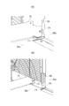
第2側壁36bの室内空間側の縁は、床面に垂直方向に仕切られてフロントパネル37に合わせ込まれる結合縁64と、結合縁64から室外空間側に窪んで第1補助冷媒管58および第2補助冷媒管63の進入を受け入れる逃げ縁65とを有する。逃げ縁65はフロントパネル37で塞がれる。図9に示されるように、逃げ縁65は樹脂材66で固められる。樹脂材66は、逃げ縁65の窪みに形成されて、第1補助冷媒管58および第2補助冷媒管63の周囲に存在する空間を埋める。図8に示されるように、外側筐体34の底板36cには、下方から第1補助冷媒管58の第4域58dおよび第2補助冷媒管63の第4域63dを支持するブラケット67が取り付けられる。ブラケット67は逃げ縁65の窪み内で第1補助冷媒管58および第2補助冷媒管63を位置決めする。
図10(A)および図10(B)に示されるように、第1側壁36aの下端には、第1側壁36aの板材から内向きに折り曲げ成型され、収納口35から開放口33まで線形に延びるガイド板71が結合される。ガイド板71には底板36cの1側縁(右縁)が第1側壁36aに平行にスライド自在に受け止められる。同様に、図示されないものの、第2側壁36bの下端には、第2側壁36bの板材から内向きに折り曲げ成型され、収納口35から開放口33まで線形に延びるガイド板が結合される。ガイド板には底板36cの他側縁(左縁)が第2側壁36bに平行にスライド自在に受け止められる。こうして底板36cは特定の範囲でガイド板71上をスライド移動することができる。底板36cの前端(室内空間側端)には、底板36cの板材から上向きに折り曲げ成型される縦壁72が結合される。縦壁72の左右端には、左右方向外側に向かって広がる重ね片73が形成される。ガイド板71の上方で第1側壁36aの前端には内向きに広がる規制片74が形成される。規制片74は第1側壁36aの板材から内向きに折り曲げ成型される。規制片74に重ね片73が重ねられると、底板36cは外側筐体34の内部空間に収容される。
室外機13は室内機12に組み合わせられてセパレート型の空気調和機11を提供する。外側筐体34が建造物壁29の開口31に嵌め込まれると、外側筐体34の内部空間39は遮音壁で室内空間から隔てられる。内部空間39から室内空間に向かって空気の流通は阻止されることができる。内部空間39に進入する外気と冷媒との間で室外機13は熱交換を実施する。熱交換の効率は良好に確保されることができる。ここで、室外空間の騒音は遮音壁で遮られる。良好に騒音の進入は防止されることができる。室内空間の静寂性は良好に確保されることができる。
建造物壁29の開口31はPTAC向けに決められた寸法を有する。ここでは、建造物壁29の開口31には室外機13のみが配置されればよいことから、送風口42と外側筐体34の第1側壁36aとの間には大きな空間が確保されることができる。こうして送風口42から熱交換後の空気は効率的に室外空間に向かって排出されることができる。室外熱交換器16を通過する空気の流量は促進されることができる。室外機13では熱交換の効率は高められることができる。
空気調和機11の設置にあたって、外側筐体34は組み立てられる。第1天壁36dに第1側壁36aおよび第2側壁36bは組み付けられる。続いて、底板36cの組み付けに先立って第1側壁36a、第2側壁36bおよび第1天壁36dの組立体は建造物壁29の開口31に設置される。組立体は室内空間から建造物壁29の開口31に挿入されればよい。ここでは、第2天壁36eの設置位置は室内空間内に維持されることができる。
図11に示されるように、第1側壁36aおよび第2側壁36bには底板36cが連結される。底板36cは第1側壁36aのガイド板71および第2側壁36bのガイド板上に設置される。このとき、底板36cは室内空間側に最大限に引き出されることができる。底板36c上に内側筐体41が設置されると、第1切り換えバルブ54および第2切り換えバルブ55は外側筐体34の収納口35よりも室内空間側に位置する。したがって、底板36cの可動範囲は、第1切り換えバルブ54および第2切り換えバルブ55と第2側壁36bの結合縁64との位置関係に基づき調整されればよい。
空気調和機11の設置にあたって第1切り換えバルブ54および第2切り換えバルブ55の接続口にはそれぞれ第1補助冷媒管58および第2補助冷媒管63が結合される。結合にあたって第1補助冷媒管58は第1接続管54bおよびブラケット67に支持されることができる。第2補助冷媒管63は接続管55bおよびブラケット67に支持されることができる。こうして第1補助冷媒管58および第2補助冷媒管63は定位置に位置決めされることができる。
第1補助冷媒管58のフレアナット57は軸線Hx回りにレンチで締め付けられる。液密に結合は確立されることができる。第2補助冷媒管63のフレアナット62は軸線Hb回りにレンチで締め付けられる。液密に結合は確立されることができる。第1補助冷媒管58および第2補助冷媒管63の結合後、収納口35から外側筐体34内に内側筐体41は収納される。このとき、フレアナット57、62は第2側壁36bの結合縁64よりも室内空間側に位置することから、第1補助冷媒管58や第2補助冷媒管63と外側筐体34の第2側壁36bとの干渉は回避されることができる。こうして外側筐体34への収納に先立ってレンチの作業は実施されることから、十分な作業スペースは確保されることができる。第1補助冷媒管58および第2補助冷媒管63の結合にあたって効率的な作業は実現されることができる。
本実施形態では、外側筐体34は、第2側壁36bに並行に壁体36に対してスライド自在に支持されて、下方から内側筐体41を支持する底板36cを備える。内側筐体41の収納にあたって底板36cは外側筐体34の壁体36に対して相対的にスライドすることができる。したがって、内側筐体41の収納作業は容易に実現されることができる。効率的な作業は実現されることができる。
底板36cが第1側壁36aのガイド板71および第2側壁36bのガイド板に沿って最大限に壁体36内に押し込まれると、内側筐体41は外側筐体34の内部空間39内に収納される。第1側壁36aでは規制片74に底板36cの重ね片73は重ねられる。同様に第2側壁36bでは規制片に底板36cの重ね片は重ねられる。
その後、第2側壁36bの逃げ縁65では第1補助冷媒管58および第2補助冷媒管63の周囲に樹脂材66の流動体は適用される。樹脂材66の固化を待って逃げ縁65は塞がれる。外側筐体34の遮音性は確保されることができる。樹脂材66の適用にあたってブラケット67は流動体の骨材として機能することから、樹脂材66は固化まで良好に逃げ縁65内に保持されることができる。
第1切り換えバルブ54および第2切り換えバルブ55の接続口にガス管22aおよび液管22bが接続された後に第1切り換えバルブ54および第2切り換えバルブ55の接続口は開弁される。こうして冷媒管内に冷媒は流通することができる。第1切り換えバルブ54および第2切り換えバルブ55の開弁にあたって水平軸線Hr、Hz回りにねじ部材56、61は駆動される。ここでは、建造物壁29の開口31には室外機13のみが配置されればよいことから、第2側壁36bと内側筐体41の第3側板45との間には十分な空間が確保されることができる。外側筐体34の内部空間39では、例えばレンチで水平軸線Hr、Hz回りにねじ部材56、61を駆動する作業は良好に実現されることができる。
内側筐体41が外側筐体34の内部空間39に収納された後に、第2天壁36eは設置されることができる。第2天壁36eは第1側壁36aの上端および第2側壁36bの上端に密に結合される。結合にあたって例えばウレタン製の遮音材は挟み込まれることができる。第1天壁36dおよび第2天壁36eの合わせ目では両者は隙間なく接する。こうして第1天壁36dは建造物壁29に埋め込まれて建造物壁29内に遮音壁を形成する。第2天壁36eが室内空間内に配置されれば、第2天壁36eの開閉に応じて内部空間39にアクセスする経路は確保されることができる。空気調和機11の設置後であっても良好なメンテナンス作業は実現されることができる。
外側筐体34の収納口35はフロントパネル37で閉じられる。外側筐体34の第2側壁36bには第1補助冷媒管58および第2補助冷媒管63の配置にあたって逃げ縁65が形成されるので、第1補助冷媒管58および第2補助冷媒管63の配置にあたって室内空間側にフロントパネル37の出っ張りは回避されることができる。建造物壁29から室外機13の出っ張りはできる限り抑制されることができる。加えて、フロントパネル37の意匠性は良好に維持されることができる。
図12に示されるように、第1補助冷媒管58および第2補助冷媒管63はフロントパネル37から引き出されてもよい。こうした構成では、外側筐体34は建造物壁29の開口31に完全に収容されることができる。建造物壁29の壁面とフロントパネル37とは面一に設定されることができる。こうして室外機13は様々な壁厚の建造物壁29に対して利用されることができる。
(変形例)
上述した除霜運転によって、例えば、室外熱交換器16に付着した霜(氷)が融解すると、除霜水が、その自重によって内側筐体41の底板48に流れ落ちる。さらに、除霜水は、底板48に設けられた孔(後述)から落下して、外側筐体34の底板36cにまで流れ落ちる。
上述した除霜運転によって、例えば、室外熱交換器16に付着した霜(氷)が融解すると、除霜水が、その自重によって内側筐体41の底板48に流れ落ちる。さらに、除霜水は、底板48に設けられた孔(後述)から落下して、外側筐体34の底板36cにまで流れ落ちる。
但し、除霜運転から暖房運転に切り替わると、開放口33から再び冷たい外気(例えば氷点下の外気)が内側筐体41内に吸引される。そして、内側筐体41内に吸引された外気の温度が氷点下である場合には、外側筐体34の底板36cに滞留した除霜水が外気に触れて、除霜水が凍結する可能性がある。そして、除霜水の凍結が繰り返されると、底板48に設けられた孔が氷で塞がれてしまい、除霜水が外側筐体34に排水されない虞がある。
従って、図13に示されるように、空気調和機11においては、外側筐体34に除霜水の凍結を防止するヒータ80が配置されてもよい。ヒータ80は、例えば、抵抗加熱型のヒータである。ヒータ80は、その内部に電流を通電させることによりジュール熱を発する。また、ヒータ周辺の部材を加熱する。
ヒータ80は、図14に示されるように、例えば、内側筐体41と外側筐体34との間に配置される。これにより、内側筐体41と外側筐体34との間で除霜水が凍結することを防ぐことができる。内側筐体41と外側筐体34との間には除霜水受け皿(以下、ドレンパン36sともいう)が設けられる(後述)。ドレンパン36sは、室外機13の室外熱交換器16に付着した霜が溶解した除霜水を一時的に貯留する。ドレンパン36sは、底面36s1と、底面36s1の外周から立設する側面36s2とを備える。
図15に、内側筐体41を取り除いたときの外側筐体34を上面視した平面を示す。図15には、外側筐体34のほかに、室外熱交換器16の外形が破線で示されている。室外熱交換器16は、図15に示されるように、L字型をなしている。
ヒータ80は、ループ状となって、底面36s1に固定具81によって固定される。ヒータ80は、底面36s1に接触する。ヒータ80の終端である端部80pと端部80nとにはヒータ80に電力を供給するための導電線(不図示)が接続される。ヒータ80への電力供給は、第1制御部25によって制御される。
外側筐体34には、破線P1で画定された領域に、ドレンパン36sが設けられている。破線P1で画定された領域の上部には内側筐体41が配置される。これにより、室外熱交換器16に付着した霜が溶解し、内側筐体41から排水される除霜水をドレンパン36sに一定量を貯留することができる。また、ヒータ80の少なくとも一部は、ドレンパン36sに収容される。この結果、ドレンパン36sに貯留した除霜水が外気によって再び凍結することを、ヒータ80が発する熱によって防ぐことができる。
また、底面36s1と底板36cとには、除霜水を外側筐体34の外側に排水する排水口36hが設けられている。また、内側筐体41または外側筐体34には、排水口36hを介して除霜水を外側筐体34の外側に排出するドレンポンプ等のポンプ(不図示)が設けられる。これにより、ドレンパン36sに溜まった除霜水はポンプによって排水され、ドレンパン36sから除霜水が溢れることが回避される。なお、ポンプは空気調和機11の運転とは連動せずに稼働されるようにできる。これにより、空気調和機11の運転停止中に、暴風雨などによりドレンパン36sに雨水が蓄積しても、ポンプに搭載されたフロートスイッチにより稼働し、排水が行われる。
また、図15に破線で示された複数の孔48hは、上下方向においてドレンパン36sの底面36s1に対向する内側筐体41の底板48に設けられた複数の孔のそれぞれの外形を示す。複数の孔48hは、室外熱交換器16の下方に位置している。除霜運転によって室外熱交換器16から流れ落ちた除霜水は、内側筐体41から複数の孔48hを介してドレンパン36sの底面36s1に落下する。また、複数の孔48hは、L字型の室外熱交換器16の外形に合わせて並設されている。ヒータ80の一部は、外側筐体34において複数の孔48hが並ぶ方向に沿うようにドレンパン36sに収容される。さらに、ヒータ80の前記一部とは別の部分が外側筐体34において排水口36hに隣接するようドレンパン36sに収容される。具体的には、ヒータ80は直線状に延びる直線部と、鋭角や鈍角に曲がる複数の曲げ部とを有する。前記直線部が孔48hの並ぶ方向に沿うように底面36s1上に配置される。そして、前記曲げ部の一つが排水口36hの縁に沿うように底面36s1上に配置される。これにより、複数の孔48h及び排水口36h、または複数の孔48h及び排水口36hのそれぞれの周辺での除霜水の凍結が回避される。さらに除霜水はヒータ80により排水口36hに導かれる。そして、除霜水を確実に複数の孔48h及び排水口36hを介して外側筐体34の外に排水することができる。除霜水はヒータ80により排水口36hに導かれるため、ヒータ80から離れた場所に除霜水が貯留しにくい。このため、除霜水の凍結を防ぐために、ヒータ80が底面36s1全体を加熱できるほど高い温度に加熱されずに済む。これにより、ヒータ80に投入する電力の増大を抑制できる。
ヒータ80を制御する第1制御部25は、例えば、内側筐体41に設けられる。第1制御部25は、室内機12に設けられた第2制御部26から暖房運転(除霜運転を含む暖房運転)を示す信号を第1制御部25が受信した場合にヒータ80を通電させる。例えば、使用者が空気調和機11の遠隔操作器(不図示)を用いて空気調和機11の暖房運転モードを選択した場合、第1制御部25は、第2制御部26から暖房運転モードを示す信号を受信してヒータ80を通電させる。ヒータ80を通電させる制御を空気調和機11に具備された第1制御部25によって行うことで、暖房運転と同期させてヒータ80を通電させることができる。
ヒータ80の消費電力を抑える制御を行うこともできる。例えばヒータ80は、第1制御部25の制御によって、暖房運転において、外気温に応じて通電が開始するよう制御されてもよく、外気温度が例えば2℃以下になると通電が開始されるようにしても良い。外気温度は外気温サーミスタ86により吸い込み空気から検出される。ヒータ80への通電開始外気温度を0℃よりも高くすることで、外気温サーミスタによる測定誤差が生じても、除霜水の凍結を防止できる。また、ヒータ80の通電開始外気温度を上げすぎないことで、無用な電力の消費が抑えられる。また、ヒータ80は、例えば外気温がマイナス15℃の場合でも、ヒータ表面温度が0℃よりも高くなるように設定する。このようにすれば、外気温度が極端に低下した場合でも、除霜水の凍結を防ぐことができる。
また、本変形例でも、第1側壁36a、第2側壁36b、(ドレンパン36sが設けられる部分を除く)底板36c、第1天壁36d、第2天壁36eおよびフロントパネル37のそれぞれの内面に遮音材が配置される。本変形例ではさらに、図16に示すように、ドレンパン36sが配置された箇所に対応する外側筐体34の外側には遮音材85が設けられている。例えば、遮音材85は、底板36cの下に配置される。遮音材85の材質としては、遮音性、断熱性、柔軟性及び加工性にすぐれた発砲ポリエチレン等が適用される。遮音材85を底板36cの下に配置することにより、内面に遮音材が配置されないドレンパン36sから、圧縮機15の音、除霜水の排水される音が内側筐体41または外側筐体34から室内へ漏れることがより確実に抑制される。また、開放口33から冷たい外気が内側筐体41内に吸引されても、遮音材85の断熱性によって外気の温度が断熱され、室内温度が外気温によって影響を受けにくくなる。なお、遮音材85は。少なくともドレンパン36sが配置された箇所に対応する外側筐体34の外側に設けられればよい。
以上、本発明の実施形態について説明したが、本発明は上述の実施形態にのみ限定されるものではなく種々変更を加え得ることは勿論である。各実施形態は、独立の形態とは限らず、技術的に可能な限り複合することができる。
11…空気調和機、12…室内機、13…室外機、14…室内熱交換器、15…圧縮機、15a…吸入管、15b…吐出管、16…室外熱交換器、17…膨張弁、18…四方弁、18a…第1口、18b…第2口、18c…第3口、18d…第4口、19…冷媒回路(冷凍回路)、21…循環経路、22…循環経路、22a…ガス管、22b…液管、23…送風ファン、24…送風ファン、25…第1制御部、26…第2制御部、29…建造物壁、31…開口、32…建造物、33…開放口、34…外側筐体、35…収納口、36…壁体、36a…側壁(第1側壁)、36b…第2側壁、36c…底板、36d…第1天壁、36e…第2天壁、36h…排水口、36s…ドレンパン、36s1…底面、36s2…側面、37…フロントパネル、38…グリル、39…(外側筐体の)内部空間、41…内側筐体、42…送風口、43…右側板(第1側板)、44…前板(第2側板)、45…側板(第3側板)、46…吸込口、47…第4側板、48…底板、48h…孔、49…天板、49a…開口、51…吸込口、52…ブレード、54…切り換えバルブ(第1切り換えバルブ)、55…切り換えバルブ(第2切り換えバルブ)、58…補助冷媒管(第1補助冷媒管)、63…補助冷媒管(第2補助冷媒管)、64…結合縁、65…逃げ縁、66…樹脂材、67…ブラケット、71…ガイド板、72…縦壁、73…重ね片、74…規制片、80…ヒータ、80p…端部、80n…端部、81…固定具、85…遮音材、86…外気温サーミスタ、Hb…(接続口の)軸線、Hr…(ねじの)軸線(水平軸線)、Hx…(接続口の)軸線、Hz…(ねじの)軸線(水平軸線)。
Claims (15)
- 室内空間の壁面に固定されて、室内熱交換器を収容する室内機と、
前記室内熱交換器を含む冷媒回路に接続される室外熱交換器を収容する室外機と
を備え、前記室外機は、
室外空間と室内空間を仕切る建造物壁に形成される開口に嵌め込まれて、前記室外空間に開放されながら遮音壁で囲まれて前記室内空間から隔てられる内部空間を区画する外側筐体と、
前記内部空間内に配置されて、前記室外熱交換器を収容する内側筐体と
を備えることを特徴とする空気調和機。 - 請求項1に記載の空気調和機において、
前記外側筐体は、前記建造物壁の壁面に直交する仮想平面に沿って広がる側壁を含んで、前記室内空間に向かって開口する収納口を区画する壁体と、前記壁体に結合されて前記収納口を塞ぐフロントパネルとを有し、
前記内側筐体は、前記室外空間に向かって開放される吸込口と、前記側壁に向かって熱交換後の空気を送り出す送風口とを有することを特徴とする空気調和機。 - 請求項2に記載の空気調和機において、
前記外側筐体は、前記壁体に含まれて、前記側壁との間に前記内側筐体を収容する第2側壁を備え、
前記冷媒回路は、前記室外熱交換器に接続されて、前記内側筐体で前記第2側壁に向き合わせられる側板から突出し、前記側板の板面に垂直に設定される軸線を回転軸とするねじの回転に基づき接続口の開閉を切り換える切り換えバルブを備えることを特徴とする空気調和機。 - 請求項1に記載の空気調和機において、
前記外側筐体は、前記建造物壁の壁面に直交する仮想平面に沿って広がる側壁を含んで、前記室内空間に向かって開口する収納口を区画する壁体と、前記壁体に結合されて前記収納口を塞ぐフロントパネルとを有し、
前記冷媒回路は、前記室外熱交換器に接続されて、前記内側筐体で前記側壁に向き合わせられる側板から突出し、前記側板の板面に並列に設定される軸線を有する接続口を形成する切り換えバルブと、前記軸線を回転軸とするフレアナットの締め付けに応じて前記接続口に結合され、前記側壁の前記室内空間側の縁よりも前記室内空間側で前記外側筐体から前記室内空間に引き出される補助冷媒管とを有することを特徴とする空気調和機。 - 請求項4に記載の空気調和機において、
前記外側筐体は、前記側壁に並行に前記壁体に対してスライド自在に支持されて、下方から前記内側筐体を支持する底板を備えることを特徴とする空気調和機。 - 請求項4または5に記載の空気調和機において、
前記側壁の室内空間側縁は、床面に垂直方向に仕切られてフロントパネルに合わせ込まれる結合縁と、前記結合縁から室外空間側に窪んで前記補助冷媒管の進入を受け入れる逃げ縁とを有することを特徴とする空気調和機。 - 請求項1に記載の空気調和機において、
前記外側筐体は、前記建造物壁の壁面に直交する仮想平面に沿って広がる左右の側壁と、前記側壁の室外空間側端から室内空間側に延びて、左右の前記側壁で挟まれる前記内部空間を上方から塞ぐ第1天壁と、前記第1天壁から室内空間側に前記側壁の室内空間側端まで延びて、開閉可能に前記内部空間を上方から塞ぐ第2天壁とを備えることを特徴とする空気調和機。 - 請求項1~7のいずれか1つに記載の空気調和機において、
前記外側筐体と前記内側筐体との間に、ヒータが配置されたことを特徴とする空気調和機。 - 請求項1~8のいずれか1つに記載の空気調和機において、
前記外側筐体は、前記室外熱交換器に付着した霜が溶解した除霜水を貯留するドレンパンと、前記除霜水を前記外側筐体の外側に排出するポンプとを有することを特徴とする空気調和機。 - 請求項9に記載の空気調和機において、
前記ヒータの少なくとも一部は、前記ドレンパンに収容されることを特徴とする空気調和機。 - 請求項8~10のいずれか1つに記載の空気調和機において、
前記内側筐体には、前記ヒータを制御する第1制御部が設けられ、
前記第1制御部は、前記室内機に設けられた第2制御部から除霜運転を含む暖房運転を示す信号を前記第2制御部が受信した場合に前記ヒータを通電させることを特徴とする空気調和機。 - 請求項11に記載の空気調和機において、
前記ヒータは、前記第1制御部によって、外気温に応じて通電が開始するように制御されることを特徴とする空気調和機。 - 請求項8~12のいずれか1つに記載の空気調和機において、
少なくとも前記ヒータが配置された箇所に対応する前記外側筐体の外側に前記遮音材をさらに具備する空気調和機。 - 請求項10~13のいずれか1つに記載の空気調和機において、
前記内側筐体の前記底板には、前記除霜水を前記ドレンパンに落下させる複数の孔が設けられ、前記ヒータの一部は、前記複数の孔が並ぶ方向に沿うように前記ドレンパンに収容される空気調和機。 - 請求項14に記載の空気調和機において、
前記ドレンパンには、前記除霜水を前記外側筐体の外側に排水する排水口が設けられ、前記ヒータの前記一部とは別の部分は、前記排水口に隣接するように前記ドレンパンに収容される空気調和機。
Priority Applications (1)
| Application Number | Priority Date | Filing Date | Title |
|---|---|---|---|
| US17/908,123 US20230114621A1 (en) | 2020-03-16 | 2021-03-15 | Air conditioner |
Applications Claiming Priority (2)
| Application Number | Priority Date | Filing Date | Title |
|---|---|---|---|
| JP2020045722A JP2023052717A (ja) | 2020-03-16 | 2020-03-16 | 空気調和機 |
| JP2020-045722 | 2020-03-16 |
Publications (1)
| Publication Number | Publication Date |
|---|---|
| WO2021187440A1 true WO2021187440A1 (ja) | 2021-09-23 |
Family
ID=77771053
Family Applications (1)
| Application Number | Title | Priority Date | Filing Date |
|---|---|---|---|
| PCT/JP2021/010436 Ceased WO2021187440A1 (ja) | 2020-03-16 | 2021-03-15 | 空気調和機 |
Country Status (3)
| Country | Link |
|---|---|
| US (1) | US20230114621A1 (ja) |
| JP (1) | JP2023052717A (ja) |
| WO (1) | WO2021187440A1 (ja) |
Cited By (6)
| Publication number | Priority date | Publication date | Assignee | Title |
|---|---|---|---|---|
| CN114234299A (zh) * | 2021-11-05 | 2022-03-25 | 耿洪宽 | 一种用于放置空调外机的房建预设结构 |
| WO2023062900A1 (ja) * | 2021-10-14 | 2023-04-20 | 株式会社富士通ゼネラル | 空気調和機 |
| WO2023062909A1 (ja) * | 2021-10-15 | 2023-04-20 | 株式会社富士通ゼネラル | 空気調和機 |
| WO2023062908A1 (ja) * | 2021-10-15 | 2023-04-20 | 株式会社富士通ゼネラル | 空気調和機 |
| WO2023062904A1 (ja) * | 2021-10-14 | 2023-04-20 | 株式会社富士通ゼネラル | 空気調和機 |
| CN116007126A (zh) * | 2023-02-24 | 2023-04-25 | 四川长虹空调有限公司 | 一种空调漏水检测方法 |
Families Citing this family (2)
| Publication number | Priority date | Publication date | Assignee | Title |
|---|---|---|---|---|
| US11592215B2 (en) | 2018-08-29 | 2023-02-28 | Waterfurnace International, Inc. | Integrated demand water heating using a capacity modulated heat pump with desuperheater |
| US20260022860A1 (en) * | 2024-07-19 | 2026-01-22 | Haier Us Appliance Solutions, Inc. | Condensate management system for an air conditioner appliance |
Citations (2)
| Publication number | Priority date | Publication date | Assignee | Title |
|---|---|---|---|---|
| JPS6441023U (ja) * | 1987-08-28 | 1989-03-10 | ||
| JPH0455641A (ja) * | 1990-06-22 | 1992-02-24 | Mitsubishi Electric Corp | 空気調和機 |
Family Cites Families (22)
| Publication number | Priority date | Publication date | Assignee | Title |
|---|---|---|---|---|
| US2362698A (en) * | 1934-10-24 | 1944-11-14 | Gen Motors Corp | Refrigerating apparatus |
| US2472792A (en) * | 1945-09-17 | 1949-06-14 | Mitchell Mfg Company | Air conditioning unit for mounting in windows |
| US2979918A (en) * | 1959-12-28 | 1961-04-18 | Gen Electric | Room air conditioner condensate disposal arrangement |
| US4332114A (en) * | 1979-02-16 | 1982-06-01 | Goebel Virgil E | Cover |
| US4308905A (en) * | 1980-03-24 | 1982-01-05 | Nancy Gallagher | Cover for air conditioner |
| US4534179A (en) * | 1984-10-04 | 1985-08-13 | General Electric Company | Air conditioning apparatus |
| US6168248B1 (en) * | 1996-04-12 | 2001-01-02 | Carrier Corporation | Containment system for packaged air conditioning unit |
| WO2002053975A1 (en) * | 2000-12-28 | 2002-07-11 | Carrier Corporation | Enclosure for an air conditioner outdoor unit |
| JP2008082684A (ja) * | 2006-09-29 | 2008-04-10 | Denso Corp | ヒートポンプ |
| KR101225977B1 (ko) * | 2007-06-14 | 2013-01-24 | 엘지전자 주식회사 | 공기조화기 및 그 제어 방법 |
| US20090145153A1 (en) * | 2007-12-11 | 2009-06-11 | Moynihan John P | Air conditioner cover |
| US20100240295A1 (en) * | 2009-03-20 | 2010-09-23 | Salman Akhtar | Air handling system |
| US20110239678A1 (en) * | 2010-03-30 | 2011-10-06 | Toyo Densen Co., Ltd. | Flare nut and refrigerant pipe set, air conditioner, and freezer including the same |
| CN104296359B (zh) * | 2014-10-16 | 2017-05-03 | 珠海格力电器股份有限公司 | 一种组合式接水盘及空调 |
| US20160209055A1 (en) * | 2015-01-20 | 2016-07-21 | Allied Air Enterprises Llc | Systems and methods for a heating and cooling unit and components thereof |
| CN106907798B (zh) * | 2017-04-20 | 2023-02-24 | 合肥学院 | 一种临窗空调机位降噪减震结构 |
| CN107101414A (zh) * | 2017-06-19 | 2017-08-29 | 广东志高暖通设备股份有限公司 | 一种空调系统装置及其所应用的窗机 |
| JP6747614B2 (ja) * | 2018-01-23 | 2020-08-26 | 三菱電機株式会社 | ヒートポンプ給湯室外機 |
| CN108426065A (zh) * | 2018-03-15 | 2018-08-21 | 江苏中关村科技产业园节能环保研究有限公司 | 一种结构优化的提升换向四通阀及流体切换方法 |
| US20200064017A1 (en) * | 2018-08-27 | 2020-02-27 | Haier Us Appliance Solutions, Inc. | Multi-layer wall sleeve for a packaged terminal air conditioner unit |
| KR102565503B1 (ko) * | 2019-01-29 | 2023-08-11 | 삼성전자주식회사 | 공기조화기 |
| US11333394B2 (en) * | 2019-08-29 | 2022-05-17 | Mitsubishi Electric Us, Inc. | System and method for draining water from an air-conditioner |
-
2020
- 2020-03-16 JP JP2020045722A patent/JP2023052717A/ja active Pending
-
2021
- 2021-03-15 US US17/908,123 patent/US20230114621A1/en active Pending
- 2021-03-15 WO PCT/JP2021/010436 patent/WO2021187440A1/ja not_active Ceased
Patent Citations (2)
| Publication number | Priority date | Publication date | Assignee | Title |
|---|---|---|---|---|
| JPS6441023U (ja) * | 1987-08-28 | 1989-03-10 | ||
| JPH0455641A (ja) * | 1990-06-22 | 1992-02-24 | Mitsubishi Electric Corp | 空気調和機 |
Cited By (12)
| Publication number | Priority date | Publication date | Assignee | Title |
|---|---|---|---|---|
| WO2023062900A1 (ja) * | 2021-10-14 | 2023-04-20 | 株式会社富士通ゼネラル | 空気調和機 |
| WO2023062904A1 (ja) * | 2021-10-14 | 2023-04-20 | 株式会社富士通ゼネラル | 空気調和機 |
| JP2023059060A (ja) * | 2021-10-14 | 2023-04-26 | 株式会社富士通ゼネラル | 空気調和機 |
| US20240361012A1 (en) * | 2021-10-14 | 2024-10-31 | Fujitsu General Limited | Air conditioner |
| US12480668B2 (en) | 2021-10-14 | 2025-11-25 | Fujitsu General Limited | Air conditioner |
| US12504180B2 (en) * | 2021-10-14 | 2025-12-23 | Fujitsu General Limited | Air conditioner |
| WO2023062909A1 (ja) * | 2021-10-15 | 2023-04-20 | 株式会社富士通ゼネラル | 空気調和機 |
| WO2023062908A1 (ja) * | 2021-10-15 | 2023-04-20 | 株式会社富士通ゼネラル | 空気調和機 |
| JP2023059386A (ja) * | 2021-10-15 | 2023-04-27 | 株式会社富士通ゼネラル | 空気調和機 |
| JP2023059385A (ja) * | 2021-10-15 | 2023-04-27 | 株式会社富士通ゼネラル | 空気調和機 |
| CN114234299A (zh) * | 2021-11-05 | 2022-03-25 | 耿洪宽 | 一种用于放置空调外机的房建预设结构 |
| CN116007126A (zh) * | 2023-02-24 | 2023-04-25 | 四川长虹空调有限公司 | 一种空调漏水检测方法 |
Also Published As
| Publication number | Publication date |
|---|---|
| US20230114621A1 (en) | 2023-04-13 |
| JP2023052717A (ja) | 2023-04-12 |
Similar Documents
| Publication | Publication Date | Title |
|---|---|---|
| WO2021187440A1 (ja) | 空気調和機 | |
| CN102395843B (zh) | 冰箱相关技术 | |
| CN110440504B (zh) | 一种冰箱 | |
| CA2674504A1 (en) | Ice storage bin and icemaker apparatus for refrigerator | |
| US20100011796A1 (en) | Refrigerator | |
| KR20190014687A (ko) | 냉장고 | |
| EP4053478A1 (en) | Refrigerator | |
| KR20220163653A (ko) | 냉장고 | |
| JP2001201108A (ja) | 空気調和機の室外ユニット | |
| CN221992165U (zh) | 制冷设备 | |
| JP6934433B2 (ja) | 冷蔵庫 | |
| JP2019138514A (ja) | 冷蔵庫 | |
| CN110873496A (zh) | 冰箱 | |
| JP6667072B2 (ja) | 冷蔵庫 | |
| CN111561798B (zh) | 冰箱 | |
| JP2023155594A (ja) | 冷蔵庫 | |
| KR101132554B1 (ko) | 냉장고 | |
| KR20110097016A (ko) | 냉장고의 제어 방법 | |
| AU2022391851B2 (en) | Refrigerator and refrigerator manufacturing method | |
| CN113432367A (zh) | 冰箱 | |
| JP2021076318A (ja) | 冷蔵庫 | |
| JP7254227B2 (ja) | 冷蔵庫 | |
| CN117870263A (zh) | 具有制冰机的冰箱 | |
| JP2902915B2 (ja) | 冷却装置 | |
| WO2023199553A1 (ja) | 冷蔵庫 |
Legal Events
| Date | Code | Title | Description |
|---|---|---|---|
| 121 | Ep: the epo has been informed by wipo that ep was designated in this application |
Ref document number: 21771640 Country of ref document: EP Kind code of ref document: A1 |
|
| NENP | Non-entry into the national phase |
Ref country code: DE |
|
| 122 | Ep: pct application non-entry in european phase |
Ref document number: 21771640 Country of ref document: EP Kind code of ref document: A1 |
|
| NENP | Non-entry into the national phase |
Ref country code: JP |