WO2021187280A1 - 操作装置 - Google Patents
操作装置 Download PDFInfo
- Publication number
- WO2021187280A1 WO2021187280A1 PCT/JP2021/009641 JP2021009641W WO2021187280A1 WO 2021187280 A1 WO2021187280 A1 WO 2021187280A1 JP 2021009641 W JP2021009641 W JP 2021009641W WO 2021187280 A1 WO2021187280 A1 WO 2021187280A1
- Authority
- WO
- WIPO (PCT)
- Prior art keywords
- resistor
- lever
- operating device
- slider
- low resistance
- Prior art date
- Legal status (The legal status is an assumption and is not a legal conclusion. Google has not performed a legal analysis and makes no representation as to the accuracy of the status listed.)
- Ceased
Links
Images





Classifications
-
- G—PHYSICS
- G06—COMPUTING OR CALCULATING; COUNTING
- G06F—ELECTRIC DIGITAL DATA PROCESSING
- G06F3/00—Input arrangements for transferring data to be processed into a form capable of being handled by the computer; Output arrangements for transferring data from processing unit to output unit, e.g. interface arrangements
- G06F3/01—Input arrangements or combined input and output arrangements for interaction between user and computer
- G06F3/03—Arrangements for converting the position or the displacement of a member into a coded form
- G06F3/033—Pointing devices displaced or positioned by the user, e.g. mice, trackballs, pens or joysticks; Accessories therefor
- G06F3/0338—Pointing devices displaced or positioned by the user, e.g. mice, trackballs, pens or joysticks; Accessories therefor with detection of limited linear or angular displacement of an operating part of the device from a neutral position, e.g. isotonic or isometric joysticks
-
- A—HUMAN NECESSITIES
- A63—SPORTS; GAMES; AMUSEMENTS
- A63F—CARD, BOARD, OR ROULETTE GAMES; INDOOR GAMES USING SMALL MOVING PLAYING BODIES; VIDEO GAMES; GAMES NOT OTHERWISE PROVIDED FOR
- A63F13/00—Video games, i.e. games using an electronically generated display having two or more dimensions
- A63F13/20—Input arrangements for video game devices
- A63F13/24—Constructional details thereof, e.g. game controllers with detachable joystick handles
-
- G—PHYSICS
- G05—CONTROLLING; REGULATING
- G05G—CONTROL DEVICES OR SYSTEMS INSOFAR AS CHARACTERISED BY MECHANICAL FEATURES ONLY
- G05G1/00—Controlling members, e.g. knobs or handles; Assemblies or arrangements thereof; Indicating position of controlling members
- G05G1/015—Arrangements for indicating the position of a controlling member
-
- G—PHYSICS
- G05—CONTROLLING; REGULATING
- G05G—CONTROL DEVICES OR SYSTEMS INSOFAR AS CHARACTERISED BY MECHANICAL FEATURES ONLY
- G05G1/00—Controlling members, e.g. knobs or handles; Assemblies or arrangements thereof; Indicating position of controlling members
- G05G1/04—Controlling members for hand actuation by pivoting movement, e.g. levers
-
- G—PHYSICS
- G06—COMPUTING OR CALCULATING; COUNTING
- G06F—ELECTRIC DIGITAL DATA PROCESSING
- G06F3/00—Input arrangements for transferring data to be processed into a form capable of being handled by the computer; Output arrangements for transferring data from processing unit to output unit, e.g. interface arrangements
- G06F3/01—Input arrangements or combined input and output arrangements for interaction between user and computer
- G06F3/03—Arrangements for converting the position or the displacement of a member into a coded form
- G06F3/033—Pointing devices displaced or positioned by the user, e.g. mice, trackballs, pens or joysticks; Accessories therefor
- G06F3/038—Control and interface arrangements therefor, e.g. drivers or device-embedded control circuitry
-
- H—ELECTRICITY
- H01—ELECTRIC ELEMENTS
- H01H—ELECTRIC SWITCHES; RELAYS; SELECTORS; EMERGENCY PROTECTIVE DEVICES
- H01H25/00—Switches with compound movement of handle or other operating part
- H01H25/04—Operating part movable angularly in more than one plane, e.g. joystick
-
- G—PHYSICS
- G05—CONTROLLING; REGULATING
- G05G—CONTROL DEVICES OR SYSTEMS INSOFAR AS CHARACTERISED BY MECHANICAL FEATURES ONLY
- G05G9/00—Manually-actuated control mechanisms provided with one single controlling member co-operating with two or more controlled members, e.g. selectively, simultaneously
- G05G9/02—Manually-actuated control mechanisms provided with one single controlling member co-operating with two or more controlled members, e.g. selectively, simultaneously the controlling member being movable in different independent ways, movement in each individual way actuating one controlled member only
- G05G9/04—Manually-actuated control mechanisms provided with one single controlling member co-operating with two or more controlled members, e.g. selectively, simultaneously the controlling member being movable in different independent ways, movement in each individual way actuating one controlled member only in which movement in two or more ways can occur simultaneously
- G05G9/047—Manually-actuated control mechanisms provided with one single controlling member co-operating with two or more controlled members, e.g. selectively, simultaneously the controlling member being movable in different independent ways, movement in each individual way actuating one controlled member only in which movement in two or more ways can occur simultaneously the controlling member being movable by hand about orthogonal axes, e.g. joysticks
- G05G2009/04703—Mounting of controlling member
- G05G2009/04714—Mounting of controlling member with orthogonal axes
- G05G2009/04718—Mounting of controlling member with orthogonal axes with cardan or gimbal type joint
-
- G—PHYSICS
- G05—CONTROLLING; REGULATING
- G05G—CONTROL DEVICES OR SYSTEMS INSOFAR AS CHARACTERISED BY MECHANICAL FEATURES ONLY
- G05G9/00—Manually-actuated control mechanisms provided with one single controlling member co-operating with two or more controlled members, e.g. selectively, simultaneously
- G05G9/02—Manually-actuated control mechanisms provided with one single controlling member co-operating with two or more controlled members, e.g. selectively, simultaneously the controlling member being movable in different independent ways, movement in each individual way actuating one controlled member only
- G05G9/04—Manually-actuated control mechanisms provided with one single controlling member co-operating with two or more controlled members, e.g. selectively, simultaneously the controlling member being movable in different independent ways, movement in each individual way actuating one controlled member only in which movement in two or more ways can occur simultaneously
- G05G9/047—Manually-actuated control mechanisms provided with one single controlling member co-operating with two or more controlled members, e.g. selectively, simultaneously the controlling member being movable in different independent ways, movement in each individual way actuating one controlled member only in which movement in two or more ways can occur simultaneously the controlling member being movable by hand about orthogonal axes, e.g. joysticks
- G05G2009/0474—Manually-actuated control mechanisms provided with one single controlling member co-operating with two or more controlled members, e.g. selectively, simultaneously the controlling member being movable in different independent ways, movement in each individual way actuating one controlled member only in which movement in two or more ways can occur simultaneously the controlling member being movable by hand about orthogonal axes, e.g. joysticks characterised by means converting mechanical movement into electric signals
-
- G—PHYSICS
- G05—CONTROLLING; REGULATING
- G05G—CONTROL DEVICES OR SYSTEMS INSOFAR AS CHARACTERISED BY MECHANICAL FEATURES ONLY
- G05G9/00—Manually-actuated control mechanisms provided with one single controlling member co-operating with two or more controlled members, e.g. selectively, simultaneously
- G05G9/02—Manually-actuated control mechanisms provided with one single controlling member co-operating with two or more controlled members, e.g. selectively, simultaneously the controlling member being movable in different independent ways, movement in each individual way actuating one controlled member only
- G05G9/04—Manually-actuated control mechanisms provided with one single controlling member co-operating with two or more controlled members, e.g. selectively, simultaneously the controlling member being movable in different independent ways, movement in each individual way actuating one controlled member only in which movement in two or more ways can occur simultaneously
- G05G9/047—Manually-actuated control mechanisms provided with one single controlling member co-operating with two or more controlled members, e.g. selectively, simultaneously the controlling member being movable in different independent ways, movement in each individual way actuating one controlled member only in which movement in two or more ways can occur simultaneously the controlling member being movable by hand about orthogonal axes, e.g. joysticks
- G05G2009/0474—Manually-actuated control mechanisms provided with one single controlling member co-operating with two or more controlled members, e.g. selectively, simultaneously the controlling member being movable in different independent ways, movement in each individual way actuating one controlled member only in which movement in two or more ways can occur simultaneously the controlling member being movable by hand about orthogonal axes, e.g. joysticks characterised by means converting mechanical movement into electric signals
- G05G2009/04751—Position sensor for linear movement
-
- G—PHYSICS
- G05—CONTROLLING; REGULATING
- G05G—CONTROL DEVICES OR SYSTEMS INSOFAR AS CHARACTERISED BY MECHANICAL FEATURES ONLY
- G05G9/00—Manually-actuated control mechanisms provided with one single controlling member co-operating with two or more controlled members, e.g. selectively, simultaneously
- G05G9/02—Manually-actuated control mechanisms provided with one single controlling member co-operating with two or more controlled members, e.g. selectively, simultaneously the controlling member being movable in different independent ways, movement in each individual way actuating one controlled member only
- G05G9/04—Manually-actuated control mechanisms provided with one single controlling member co-operating with two or more controlled members, e.g. selectively, simultaneously the controlling member being movable in different independent ways, movement in each individual way actuating one controlled member only in which movement in two or more ways can occur simultaneously
- G05G9/047—Manually-actuated control mechanisms provided with one single controlling member co-operating with two or more controlled members, e.g. selectively, simultaneously the controlling member being movable in different independent ways, movement in each individual way actuating one controlled member only in which movement in two or more ways can occur simultaneously the controlling member being movable by hand about orthogonal axes, e.g. joysticks
- G05G2009/04766—Manually-actuated control mechanisms provided with one single controlling member co-operating with two or more controlled members, e.g. selectively, simultaneously the controlling member being movable in different independent ways, movement in each individual way actuating one controlled member only in which movement in two or more ways can occur simultaneously the controlling member being movable by hand about orthogonal axes, e.g. joysticks providing feel, e.g. indexing means, means to create counterforce
-
- G—PHYSICS
- G05—CONTROLLING; REGULATING
- G05G—CONTROL DEVICES OR SYSTEMS INSOFAR AS CHARACTERISED BY MECHANICAL FEATURES ONLY
- G05G9/00—Manually-actuated control mechanisms provided with one single controlling member co-operating with two or more controlled members, e.g. selectively, simultaneously
- G05G9/02—Manually-actuated control mechanisms provided with one single controlling member co-operating with two or more controlled members, e.g. selectively, simultaneously the controlling member being movable in different independent ways, movement in each individual way actuating one controlled member only
- G05G9/04—Manually-actuated control mechanisms provided with one single controlling member co-operating with two or more controlled members, e.g. selectively, simultaneously the controlling member being movable in different independent ways, movement in each individual way actuating one controlled member only in which movement in two or more ways can occur simultaneously
- G05G9/047—Manually-actuated control mechanisms provided with one single controlling member co-operating with two or more controlled members, e.g. selectively, simultaneously the controlling member being movable in different independent ways, movement in each individual way actuating one controlled member only in which movement in two or more ways can occur simultaneously the controlling member being movable by hand about orthogonal axes, e.g. joysticks
Definitions
- the present invention relates to an operating device.
- Patent Document 1 regarding an operating device that detects the inclination of the operating shaft using a variable resistor, the inclination of the change in the output in the neutral position region is set to the neutral position by processing with an analog amplifier circuit or a digital circuit.
- a technique has been disclosed in which the slope of the change in output outside the region is made smaller than the slope. According to this technology, it is said that the apparent return accuracy of the lever can be improved.
- the operating device is a lever that can be tilted, a flat and strip-shaped resistor provided on the surface of the substrate, and slides on the surface of the resistor as the lever is tilted.
- the resistor includes a slider that changes the output voltage value depending on the lever, and the resistor has a low resistance portion having a resistance value lower than that of other portions at a portion that the slider abuts when the lever is in the neutral state.
- the output voltage value is changed by sliding on the surface of the flat and band-shaped resistor provided on the surface of the substrate and the surface of the resistor as the lever is tilted.
- an operating device that uses a slider to be operated as a variable resistor it is possible to improve the accuracy of returning the lever to the neutral position in the output voltage value output from the operating device without using signal processing.
- External perspective view of the operating device according to one embodiment External perspective view of the operating device (with the case removed) according to the embodiment.
- Cross-sectional view of the operating device according to one embodiment Top view of FPC included in the operating device according to the embodiment The figure which shows the contact state of the slider provided in the operation apparatus which concerns on one Embodiment.
- Top view of FPC included in the operating device according to the actual modification The figure which shows the contact state of the slider provided in the operation device which concerns on one actual deformation example.
- FIG. 1 is an external perspective view of the operating device 100 according to the embodiment.
- the Z-axis direction in the figure is the vertical direction
- the X-axis direction in the figure is the front-rear direction
- the Y-axis direction in the figure is the left-right direction.
- the operation device 100 shown in FIG. 1 is used for a controller or the like of a game machine or the like.
- the operating device 100 has a columnar, tiltable lever 120 extending upward from the opening 102A of the case 102.
- the operating device 100 can tilt the lever 120 not only in the front-rear direction (arrows D1 and D2 in the figure) and in the left-right direction (arrows D3 and D4 in the figure) but also in all directions between these directions. be.
- the operation device 100 can output an operation signal corresponding to the tilt operation (tilt direction and tilt angle) of the lever 120 to the outside via the FPC (Flexible Printed Circuits) 112.
- FPC Flexible Printed Circuits
- FIG. 2 is an external perspective view of the operating device 100 (state in which the case 102 is removed) according to the embodiment.
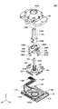
- FIG. 3 is an exploded perspective view of the operating device 100 according to the embodiment.
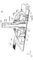
- FIG. 4 is a cross-sectional view of the operating device 100 according to the embodiment.
- the operating device 100 includes a case 102, a lever 120, an actuator 104, a holder 105, an actuator 106, an actuator 103, a spring 108, a holder 107, a pressing member 109, a frame 110, an FPC 112, and a metal.
- a sheet 113 is provided.
- the case 102 has an upwardly convex dome shape.
- each component (lever 120, actuator 103, 104, 106, and holder 105, 107) is incorporated in the internal space.
- an opening 102A having a circular shape in a plan view from above is formed at the top of a portion having a dome shape.
- the lever 120 is a member that is tilted by the operator.
- the lever 120 has a lever portion 120A and a base portion 120B.
- the lever portion 120A is a substantially columnar portion extending upward from the opening 102A of the case 102, and is a portion that is tilted by the operator.
- the base portion 120B is a substantially columnar portion that supports the lower end portion of the lever portion 120A inside the case 102 and rotates as the lever portion 120A is tilted.
- the actuator 104 has a dome shape that is convexly curved upward, and has an elongated hole-shaped opening 104A that extends in the left-right direction (Y-axis direction in the figure) along the curved shape.
- the actuator 104 has a rotation shaft 104B protruding outward at each of both ends in the left-right direction, and the rotation shaft 104B is supported by the case 102 so that the rotation shaft 104B is the center of rotation. , Is rotatably provided in the front-rear direction (X-axis direction in the figure).
- the actuator 106 is provided so as to be overlapped on the upper side of the actuator 104.
- the actuator 106 has an upwardly curved shape, and has an elongated hole-shaped opening 106A extending in the front-rear direction (X-axis direction in the drawing) along the curved shape.
- the actuator 106 has a rotation shaft 106B protruding outward at each of both ends in the front-rear direction, and the rotation shaft 106B is supported by the case 102 so that the rotation shaft 106B is the center of rotation. , Is rotatably provided in the left-right direction (Y-axis direction in the figure).
- the holder 105 holds the slider 105A on the lower side.
- the holder 105 has a longitudinal shape extending in the sliding direction (X-axis direction) of the slider 105A.
- the holder 105 is slidably provided in the sliding direction (X-axis direction) of the slider 105A.
- a protrusion 105B is provided at the center of the side surface of the holder 105.
- the holder 107 holds the slider 107A on the lower side.
- the holder 107 has a longitudinal shape extending in the sliding direction (Y-axis direction) of the slider 107A.
- the holder 107 is slidably provided in the sliding direction (Y-axis direction) of the slider 107A.
- a protrusion 107B is provided at the center of the side surface of the holder 107.
- the actuator 104 and the actuator 106 overlap each other so that the opening 104A and the opening 106A intersect each other.
- the actuator 104 and the actuator 106 are in the case 102 together with the base 120B in a state where the lever portion 120A of the lever 120 penetrates the opening 104A and the opening 106A and is assembled to the base 120B of the lever 120 in a state where they overlap each other. Is incorporated into.
- the actuator 104 has an engaging portion 104C protruding downward from the rotation shaft 104B on the positive side of the Y axis.
- the engaging portion 104C engages with a protrusion 105B provided at the center of the side surface of the holder 105 slidably provided on the FPC 112 in the front-rear direction (X-axis direction).
- the actuator 104 rotates in the front-rear direction together with the base 120B of the lever 120 and slides the holder 105 in the front-rear direction.
- the electrical connection state between the slider 105A see FIG.
- the actuator 106 has an engaging portion 106C protruding downward from the rotation shaft 106B on the positive side of the X axis.
- the engaging portion 106C engages with a protrusion 107B provided at the center of the side surface of the holder 107 slidably provided on the FPC 112 in the left-right direction (Y-axis direction).
- the actuator 106 rotates in the left-right direction together with the base 120B of the lever 120 and slides the holder 107 in the left-right direction.
- the electrical connection state between the slider 107A see FIG.
- the actuator 103 has a shaft portion 103A and a bottom plate portion 103B.
- the shaft portion 103A is a round bar-shaped portion that is inserted and arranged in the through hole 120C of the lever 120.
- the bottom plate portion 103B is a disk-shaped portion integrally provided at the lower end portion of the shaft portion 103A.
- the spring 108 is incorporated into the opening (see FIG. 4) on the bottom surface side (Z-axis negative side) of the lever 120 together with the actuator 103 in a state where the shaft portion 103A of the actuator 103 is inserted.
- the spring 108 urges the lever 120 upward and the bottom plate portion 103B of the actuator 103 downward.
- the spring 108 presses the bottom plate portion 103B of the actuator 103 against the upper surface and the central portion of the frame 110 to bring the bottom plate portion 103B into a horizontal state. This returns the lever 120 to the neutral state.
- the pressing member 109 When the lever 120 is pushed down, the pressing member 109 is pushed down by the rotation shaft 104B on the negative side of the Y axis of the actuator 104, thereby pushing down the metal sheet 113 provided on the FPC 112.
- the switch circuit formed on the FPC 112 By elastically deforming the metal sheet 113, the switch circuit formed on the FPC 112 is brought into a conductive state. As a result, the FPC 112 outputs a switch-on signal indicating that the lever 120 has been pushed downward.
- the frame 110 is a metal and flat plate-shaped member that closes the opening on the bottom surface side of the case 102.
- the frame 110 is formed by performing various processing methods (for example, punching processing, bending processing, etc.) on a metal plate.
- the frame 110 is provided with a pair of claw portions 110A on each of the front side (X-axis positive side) edge portion and the rear side (X-axis negative side) edge portion.
- the frame 110 is fixedly coupled to the case 102 by engaging each claw portion 110A with the edge portion of the case 102.
- FPC112 is an example of a "board" and is a flexible film-like wiring member.
- the FPC 112 has an extending portion 112A extending from the upper surface of the frame 110 to the side of the frame 110 (in the negative direction of the Y axis in the drawing), and is provided by a connecting portion 112B provided at the tip of the extending portion 112A. , Connected to the outside.
- the FPC 112 transmits an operation signal corresponding to the operation of the lever 120 (tilting operation and pressing operation) to the outside.
- the FPC112 covers both surfaces of a strip-shaped conductor wiring (for example, copper foil, etc.) with a film-like material having flexibility and insulation (for example, polyimide resin, polyethylene terephthalate (PET), etc.). Consists of.
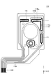
- FIG. 5 is a plan view of the FPC 112 included in the operating device 100 according to the embodiment.
- the surface of the FPC 112 is provided with the resistor 115, the resistor 116, and the resistor 117, all of which are flat and strip-shaped.
- each of the resistor 115, the resistor 116, and the resistor 117 is formed by printing in a thin film using a carbon fiber material.
- the resistor 115 is provided near the edge on the positive side of the X-axis in the FPC 112.
- the resistor 115 has a strip shape extending linearly in the Y-axis direction.
- the resistor 116 is provided near the edge on the positive side of the Y-axis in the FPC 112.
- the resistor 116 has a strip shape extending linearly in the X-axis direction.
- the resistor 117 is provided in the vicinity of the corner portion on the positive side of the X-axis and the positive side of the Y-axis in the FPC 112.
- the resistor 117 has an L shape including a straight line portion 117A and a straight line portion 117B.
- the straight portion 117A has a strip shape extending linearly in the Y-axis direction.
- the straight portion 117B has a strip shape extending linearly in the X-axis direction.
- FIG. 6 is a diagram showing a contact state of the sliders 105A and 107A included in the operating device 100 according to the embodiment.
- the linear portion 117A of the resistor 117 and the resistor 115 are provided in a straight line in the Y-axis direction so as to be separated from each other.
- a metal and leaf spring-shaped slider 107A held under the holder 107 slides in the Y-axis direction.
- a contact portion 107Aa provided at the end on the negative side of the Y-axis of the slider 107A slides on the surface of the resistor 115.
- a contact portion 107Ab provided at the end on the positive side of the Y-axis of the slider 107A slides on the surface of the straight portion 117A.
- the linear portion 117B of the resistor 117 and the resistor 116 are provided in a straight line in the X-axis direction so as to be separated from each other.
- a metal and leaf spring-shaped slider 105A held under the holder 105 slides in the X-axis direction.
- a contact portion 105Aa provided at the end on the negative side of the X-axis of the slider 105A slides on the surface of the resistor 116.
- a contact portion 105Ab provided at the end on the positive side of the X-axis of the slider 105A slides on the surface of the straight portion 117B.
- the slider 107A slides in the Y-axis direction on the surfaces of the straight line portion 117A and the resistor 115 as the lever 120 is tilted in the Y-axis direction. Move.
- the resistance value between the terminal connected to the resistor 117 and the terminal connected to the resistor 115 changes according to the amount of movement of the slider 107A (that is, the tilt angle of the lever 120).
- An external device can detect the tilting operation and tilting angle of the lever 120 in the Y-axis direction based on the change in the resistance value between the two terminals.
- the slider 105A slides in the X-axis direction on the surfaces of the straight line portion 117B and the resistor 116 as the lever 120 is tilted in the X-axis direction. ..
- the resistance value between the terminal connected to the resistor 117 and the terminal connected to the resistor 116 changes according to the amount of movement of the slider 105A (that is, the tilt angle of the lever 120).
- An external device can detect the tilting operation and tilting angle of the lever 120 in the X-axis direction based on the change in the resistance value between the two terminals.
- the straight portion 117A of the resistor 117 has a low resistance portion 117Aa.
- the low resistance portion 117Aa is a portion having a lower resistance value than the other portions of the straight portion 117A.
- the low resistance portion 117Aa is a portion that the contact portion 107Ab of the slider 107A comes into contact with when the lever 120 is in the neutral state.
- the low resistance portion 117Aa has a larger number of layers (that is, a larger thickness) of the resistors 117 than the other portions of the straight portion 117A, so that the resistance value of the low resistance portion 117Aa is larger than that of the other portions of the straight portion 117A.
- the resistor 117 has two layers in the low resistance portion 117Aa, and the resistor 117 has one layer in the other portion of the straight portion 117A. .. Specifically, in the low resistance portion 117Aa, the resistor that covers only the low resistance portion 117Aa in the straight portion 117A and the resistor that covers the entire range in the straight portion 117A overlap with each other. 117 has two layers. As a result, in the examples shown in FIGS. 5 and 6, the resistance value of the low resistance portion 117Aa is half the resistance value of the other portion of the straight portion 117A.
- the straight portion 117B of the resistor 117 has a low resistance portion 117Ba.
- the low resistance portion 117Ba is a portion having a lower resistance value than the other portions of the straight portion 117B.
- the low resistance portion 117Ba is a portion that the contact portion 105Ab of the slider 105A comes into contact with when the lever 120 is in the neutral state.
- the low resistance portion 117Ba has a larger number of layers (that is, a larger thickness) of the resistors 117 than the other portions of the straight portion 117B, so that the resistance value is higher than that of the other portions of the straight portion 117B. Is lowered.
- the resistor 117 has two layers in the low resistance portion 117Ba, and the resistor 117 has one layer in the other portion of the straight portion 117B. .. Specifically, in the low resistance portion 117Ba, the resistor that covers only the low resistance portion 117Ba in the straight portion 117B and the resistor that covers the entire range in the straight portion 117B are overlapped with each other. 117 has two layers. As a result, in the examples shown in FIGS. 5 and 6, the resistance value of the low resistance portion 117Ba is half the resistance value of the other portion of the straight portion 117B.
- FIG. 9 is a diagram showing the output characteristics of the operating device 100 according to the embodiment.
- the graph shown in FIG. 9 shows the relationship between the length of the resistor 117 (the length of the linear portions 117A and 117B) and the output voltage value.
- the maximum length of the resistor 117 is set to "5 mm”
- the length of the resistor 117 when the lever 120 is in the neutral state is set to "2.5 mm”.
- the lengths of the low resistance portions 117Aa and 117Ba are set to "1.0 mm”.
- the resistance values of the low resistance portions 117Aa and 117Ba are set to half of the resistance values of the other portions of the straight portions 117A and 117B.
- the output voltage when the low resistance portions 117Aa and 117Ba are provided is represented by a solid line
- the output voltage when the low resistance portions 117Aa and 117Ba are not provided is represented by a broken line as a comparative example.
- the slope of the output voltage value is constant over the entire range of the straight portions 117A and 117B.
- the range width of the output voltage value becomes "1".
- the range width of the output voltage value is "0.5V" (that is, half of the case where the low resistance portions 117Aa and 117Ba are not provided. It is 1).
- the operating device 100 by lowering the resistance values of the low resistance portions 117Aa and 117Ba, the inclination of the output voltage value near the neutral position of the lever 120 is made gentle, and the lever 120 is neutralized.
- the range width of the output voltage value near the position can be narrowed.
- the operating device 100 according to the embodiment sets the output voltage value to a predetermined output voltage value corresponding to the neutral position of the lever 120 even when a physical recovery error of the lever 120 occurs. You can get closer. Therefore, the operating device 100 according to the embodiment can further improve the accuracy of returning the lever 120 to the neutral position at the output voltage value output by the operating device 100, regardless of signal processing.
- the resistors covering the entire range of the straight portions 117A and 117B are overlapped on the resistors having the range of only the low resistance portions 117Aa and 117Ba of the straight portions 117A and 117B. You may. As a result, it is possible to prevent the sliders 107A and 105A from being caught at the boundary between the low resistance portions 117Aa and 117Ba and other portions.
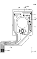
- FIG. 7 is a plan view of the FPC 112-2 included in the operating device 100 according to the modified example.
- FPC112-2 shown in FIG. 7 is a modification of FPC112 shown in FIG.
- the FPC 112-2 differs from the FPC 112 shown in FIG. 5 in that it includes a resistor 118 instead of the resistor 117.
- the resistor 118 is formed, for example, by being printed in a thin film using a carbon fiber material.
- the resistor 118 is provided in the vicinity of the corner portion on the positive side of the X-axis and the positive side of the Y-axis in the FPC 112-2.
- the resistor 118 has an L shape including a straight portion 118A and a straight portion 118B.
- the straight portion 118A has a strip shape extending linearly in the Y-axis direction.
- the straight portion 118B has a strip shape extending linearly in the X-axis direction.
- FIG. 8 is a diagram showing a contact state of the sliders 105A and 107A included in the operating device 100 according to the modified example.
- the linear portion 118A of the resistor 118 and the resistor 115 are provided in a straight line in the Y-axis direction so as to be separated from each other.
- a metal and leaf spring-shaped slider 107A held under the holder 107 slides in the Y-axis direction.
- a contact portion 107Aa provided at the end on the negative side of the Y-axis of the slider 107A slides on the surface of the resistor 115.
- a contact portion 107Ab provided at the end on the positive side of the Y-axis of the slider 107A slides on the surface of the straight portion 118A.
- the linear portion 118B of the resistor 118 and the resistor 116 are provided in a straight line in the X-axis direction so as to be separated from each other.
- a metal and leaf spring-shaped slider 105A held under the holder 105 slides in the X-axis direction.
- a contact portion 105Aa provided at the end on the negative side of the X-axis of the slider 105A slides on the surface of the resistor 116.
- a contact portion 105Ab provided at the end on the positive side of the X-axis of the slider 105A slides on the surface of the straight portion 118B.
- the slider 107A slides in the Y-axis direction on the surfaces of the straight portion 118A and the resistor 115 as the lever 120 is tilted in the Y-axis direction. Move.
- the resistance value between the terminal connected to the resistor 118 and the terminal connected to the resistor 115 changes according to the amount of movement of the slider 107A (that is, the tilt angle of the lever 120).
- An external device can detect the tilting operation and tilting angle of the lever 120 in the Y-axis direction based on the change in the resistance value between the two terminals.
- the slider 105A slides in the X-axis direction on the surfaces of the straight line portion 118B and the resistor 116 as the lever 120 is tilted in the X-axis direction. ..
- the resistance value between the terminal connected to the resistor 118 and the terminal connected to the resistor 116 changes according to the amount of movement of the slider 105A (that is, the tilt angle of the lever 120).
- An external device can detect the tilting operation and tilting angle of the lever 120 in the X-axis direction based on the change in the resistance value between the two terminals.
- the straight portion 118A of the resistor 118 has a low resistance portion 118Aa.
- the low resistance portion 118Aa is a portion having a lower resistance value than the other portions of the straight portion 118A.
- the low resistance portion 118Aa is a portion that the contact portion 107Ab of the slider 107A comes into contact with when the lever 120 is in the neutral state.
- the low resistance portion 118Aa has a lower resistance value than the other portion of the straight portion 118A because the width of the resistor 118 is larger than that of the other portion of the straight portion 118A.
- the width of the resistor 118 in the low resistance portion 118Aa is twice the width of the resistor 118 in the other portion of the straight portion 118A.
- the resistance value of the low resistance portion 118Aa is half the resistance value of the other portion of the straight portion 118A.
- the straight portion 118B of the resistor 118 has the low resistance portion 118Ba.
- the low resistance portion 118Ba is a portion having a lower resistance value than the other portions of the straight portion 118B.
- the low resistance portion 118Ba is a portion that the contact portion 105Ab of the slider 105A comes into contact with when the lever 120 is in the neutral state.
- the low resistance portion 118Ba has a lower resistance value than the other portion of the straight portion 118B because the width of the resistor 118 is larger than that of the other portion of the straight portion 118B.
- the width of the resistor 118 in the low resistance portion 118Ba is twice the width of the resistor 118 in the other portion of the straight portion 118B.
- the resistance value of the low resistance portion 118Ba is half the resistance value of the other portion of the straight portion 118B.
- the same output characteristics as those shown in FIG. 9 can be obtained. That is, even in the operating device 100 according to the modified example, the slope of the output voltage value near the neutral position of the lever 120 can be made gentle, and the range width of the output voltage value near the neutral position of the lever 120 can be narrowed. As a result, the operating device 100 according to the modification corresponds to the output voltage value corresponding to the neutral position of the lever 120 even when a physical recovery error of the lever 120 occurs, regardless of signal processing. It can be closer to the predetermined output voltage value. Therefore, the operating device 100 according to the modified example can further improve the accuracy of returning the lever 120 to the neutral position at the output voltage value output by the operating device 100, regardless of signal processing.
- the operating device 100 engages the engaging portions 104C and 106C of the actuators 104 and 106 with the protrusions 105B and 107B provided at the central portions of the holders 105 and 107, thereby engaging the holders 105 and 105.
- a configuration in which the 107 is slid is adopted. Therefore, in the operating device 100 according to the modified example, the holders 105 and 107 rotate around the central portion due to the rattling between the protrusions 105B and 107B and the engaging portions 104C and 106C. There is a risk that it will end up. In this case, the contact portions 105Ab and 107Ab of the sliders 105A and 107A may rotate in the width direction of the resistor 118.
- the width of the resistor 118 in the low resistance portions 118Aa and 118Ba is expanded, so that the contact portions 105Ab and 107Ab of the sliders 105A and 107A are oriented in the width direction of the resistor 118. Even when the sliders 105A and 107A are rotated, it is possible to prevent the contact portions 105Ab and 107Ab of the sliders 105A and 107A from deviating from the resistor 118.
- the low resistance portion may be configured so that the resistance value gradually decreases from other portions.
- the low resistance portion may be configured such that the thickness of the resistor gradually increases from the other portion, so that the resistance value gradually decreases from the other portion.
- the low resistance portion may be configured such that the width of the resistor gradually increases from the other portion so that the resistance value gradually decreases from the other portion.
Landscapes
- Engineering & Computer Science (AREA)
- Physics & Mathematics (AREA)
- General Physics & Mathematics (AREA)
- Multimedia (AREA)
- General Engineering & Computer Science (AREA)
- Theoretical Computer Science (AREA)
- Human Computer Interaction (AREA)
- Automation & Control Theory (AREA)
- Adjustable Resistors (AREA)
- Position Input By Displaying (AREA)
- Switches With Compound Operations (AREA)
Abstract
Description
図1は、一実施形態に係る操作装置100の外観斜視図である。なお、以降の説明では、便宜上、図中Z軸方向を、上下方向とし、図中X軸方向を、前後方向とし、図中Y軸方向を、左右方向とする。
図2は、一実施形態に係る操作装置100(ケース102が取り外された状態)の外観斜視図である。図3は、一実施形態に係る操作装置100の分解斜視図である。図4は、一実施形態に係る操作装置100の断面図である。
図5は、一実施形態に係る操作装置100が備えるFPC112の平面図である。図5に示すように、FPC112の表面には、いずれも平面状且つ帯状の、抵抗体115、抵抗体116、および抵抗体117が設けられている。例えば、抵抗体115、抵抗体116、および抵抗体117の各々は、炭素繊維素材が用いられて薄膜状に印刷されることによって形成される。
図6は、一実施形態に係る操作装置100が備える摺動子105A,107Aの接触状態を示す図である。
図9は、一実施形態に係る操作装置100の出力特性を示す図である。図9に示すグラフは、抵抗体117の長さ(直線部117A,117Bの長さ)と、出力電圧値との関係を示す。なお、図7に示す例では、抵抗体117の最大長さを「5mm」とし、レバー120が中立状態にあるときの抵抗体117の長さを「2.5mm」としている。また、低抵抗部117Aa,117Baの長さを「1.0mm」としている。また、低抵抗部117Aa,117Baの抵抗値を、直線部117A,117Bの他の部分の抵抗値の2分の1としている。なお、図9では、低抵抗部117Aa,117Baを設けた場合の出力電圧を実線で表し、比較例として低抵抗部117Aa,117Baを設けない場合を出力電圧を破線で表す。
(FPC112-2の構成)
図7は、一変形例に係る操作装置100が備えるFPC112-2の平面図である。図7に示すFPC112-2は、図5に示すFPC112の一変形例である。図7に示すように、FPC112-2は、抵抗体117の代わりに抵抗体118を備える点で、図5に示すFPC112と異なる。
図8は、一変形例に係る操作装置100が備える摺動子105A,107Aの接触状態を示す図である。
102 ケース
102A 開口部
103 アクチュエータ
103A 軸部
103B 底板部
104 アクチュエータ
104C 係合部
105 ホルダ
105A 摺動子
105B 突起
106 アクチュエータ
106C 係合部
107 ホルダ
107A 摺動子
107B 突起
108 スプリング
109 押圧部材
110 フレーム
112 FPC(基板)
113 メタルシート
117 抵抗体
117A,117B 直線部
117Aa,117Ba 低抵抗部
118 抵抗体
118A,118B 直線部
118Aa,118Ba 低抵抗部
120 レバー
120A レバー部
120B 基部
120C 貫通孔
Claims (4)
- 傾倒操作可能なレバーと、
基板の表面に設けられた平面状且つ帯状の抵抗体と、
前記レバーの傾倒操作に伴って、前記抵抗体の表面上を摺動することによって出力電圧値を変化させる摺動子と
を備え、
前記抵抗体は、
前記レバーが中立状態にあるときに前記摺動子が当接する部分に、他の部分よりも抵抗値が低い低抵抗部を有する
ことを特徴とする操作装置。 - 前記低抵抗部は、
前記抵抗体の厚さが前記他の部分よりも厚いことにより、前記他の部分よりも抵抗値が低い
ことを特徴とする請求項1に記載の操作装置。 - 前記低抵抗部は、
前記抵抗体の幅が前記他の部分よりも大きいことにより、前記他の部分よりも抵抗値が低い
ことを特徴とする請求項1に記載の操作装置。 - 前記摺動子は、
当該摺動子の摺動方向に延在する長手形状を有し、
前記操作装置は、
前記摺動方向に延在する長手形状を有し、前記摺動子を下側に保持するホルダと、
前記ホルダの前記摺動方向における中央部に係合する係合部を有し、前記レバーの傾倒操作に伴って、前記ホルダを前記摺動方向にスライドさせるアクチュエータと
をさらに備えることを特徴とする請求項1から2のいずれか一項に記載の操作装置。
Priority Applications (3)
| Application Number | Priority Date | Filing Date | Title |
|---|---|---|---|
| CN202180019837.9A CN115280450B (zh) | 2020-03-16 | 2021-03-10 | 操作装置 |
| JP2022508263A JP7349556B2 (ja) | 2020-03-16 | 2021-03-10 | 操作装置 |
| US17/930,099 US12105895B2 (en) | 2020-03-16 | 2022-09-07 | Operating device using variable resistor |
Applications Claiming Priority (2)
| Application Number | Priority Date | Filing Date | Title |
|---|---|---|---|
| JP2020045117 | 2020-03-16 | ||
| JP2020-045117 | 2020-03-16 |
Related Child Applications (1)
| Application Number | Title | Priority Date | Filing Date |
|---|---|---|---|
| US17/930,099 Continuation US12105895B2 (en) | 2020-03-16 | 2022-09-07 | Operating device using variable resistor |
Publications (1)
| Publication Number | Publication Date |
|---|---|
| WO2021187280A1 true WO2021187280A1 (ja) | 2021-09-23 |
Family
ID=77768272
Family Applications (1)
| Application Number | Title | Priority Date | Filing Date |
|---|---|---|---|
| PCT/JP2021/009641 Ceased WO2021187280A1 (ja) | 2020-03-16 | 2021-03-10 | 操作装置 |
Country Status (4)
| Country | Link |
|---|---|
| US (1) | US12105895B2 (ja) |
| JP (1) | JP7349556B2 (ja) |
| CN (1) | CN115280450B (ja) |
| WO (1) | WO2021187280A1 (ja) |
Citations (4)
| Publication number | Priority date | Publication date | Assignee | Title |
|---|---|---|---|---|
| JPS5638407U (ja) * | 1979-02-17 | 1981-04-11 | ||
| JP2001022462A (ja) * | 1999-07-05 | 2001-01-26 | Alps Electric Co Ltd | 多方向入力装置 |
| JP2009009799A (ja) * | 2007-06-27 | 2009-01-15 | Alps Electric Co Ltd | 多方向入力装置 |
| JP2019160457A (ja) * | 2018-03-08 | 2019-09-19 | ホシデン株式会社 | スイッチ及びこれを備えた多方向入力装置 |
Family Cites Families (9)
| Publication number | Priority date | Publication date | Assignee | Title |
|---|---|---|---|---|
| US4864272A (en) * | 1987-05-28 | 1989-09-05 | Suncom, Inc. | Joystick controller |
| JP3704432B2 (ja) * | 1998-07-06 | 2005-10-12 | 佐鳥エス・テック株式会社 | 電動工具用トリガースイッチ回路 |
| TW463078B (en) | 1999-07-05 | 2001-11-11 | Alps Electric Co Ltd | Multidirectional input device |
| CN1323725C (zh) * | 2002-08-30 | 2007-07-04 | 日晷公司 | 用于构成对加热元件电路非线性补偿的可变电阻器的方法和装置 |
| CA2638113A1 (en) * | 2007-07-27 | 2009-01-27 | The Hartfiel Company | Hydraulic actuator control system for refuse vehicles |
| JP5230517B2 (ja) * | 2009-04-24 | 2013-07-10 | アルプス電気株式会社 | 位置検出装置 |
| CN101995917B (zh) * | 2009-08-20 | 2012-03-14 | 鸿富锦精密工业(深圳)有限公司 | 具有操纵杆的电子装置 |
| JP2014002595A (ja) | 2012-06-19 | 2014-01-09 | Alps Electric Co Ltd | 操作装置 |
| JP7021040B2 (ja) * | 2018-09-25 | 2022-02-16 | ホシデン株式会社 | 多方向入力装置 |
-
2021
- 2021-03-10 WO PCT/JP2021/009641 patent/WO2021187280A1/ja not_active Ceased
- 2021-03-10 CN CN202180019837.9A patent/CN115280450B/zh active Active
- 2021-03-10 JP JP2022508263A patent/JP7349556B2/ja active Active
-
2022
- 2022-09-07 US US17/930,099 patent/US12105895B2/en active Active
Patent Citations (4)
| Publication number | Priority date | Publication date | Assignee | Title |
|---|---|---|---|---|
| JPS5638407U (ja) * | 1979-02-17 | 1981-04-11 | ||
| JP2001022462A (ja) * | 1999-07-05 | 2001-01-26 | Alps Electric Co Ltd | 多方向入力装置 |
| JP2009009799A (ja) * | 2007-06-27 | 2009-01-15 | Alps Electric Co Ltd | 多方向入力装置 |
| JP2019160457A (ja) * | 2018-03-08 | 2019-09-19 | ホシデン株式会社 | スイッチ及びこれを備えた多方向入力装置 |
Also Published As
| Publication number | Publication date |
|---|---|
| CN115280450A (zh) | 2022-11-01 |
| JP7349556B2 (ja) | 2023-09-22 |
| US12105895B2 (en) | 2024-10-01 |
| US20230004235A1 (en) | 2023-01-05 |
| CN115280450B (zh) | 2025-03-21 |
| JPWO2021187280A1 (ja) | 2021-09-23 |
Similar Documents
| Publication | Publication Date | Title |
|---|---|---|
| US12174654B2 (en) | Operation device for inproving accuracy of value of output signal indicating a neutral position | |
| US9672994B2 (en) | Device for operating multiple functions in a motor vehicle | |
| US10768658B2 (en) | Multi-directional input device | |
| JP4503424B2 (ja) | 多段スイッチ装置 | |
| WO2002013219A1 (en) | Multidirectional input device and electronic apparatus comprising it | |
| US6504115B2 (en) | Multidirectional input device | |
| JP3934330B2 (ja) | 多方向入力装置 | |
| JP7349556B2 (ja) | 操作装置 | |
| CN1465004A (zh) | 多向输入装置及使用该装置的电子设备 | |
| CN113383287B (zh) | 操作装置 | |
| JP7442637B2 (ja) | 操作装置 | |
| JP7782031B2 (ja) | 操作装置 | |
| JP7783955B2 (ja) | 多方向入力装置 | |
| US7939775B2 (en) | Button unit for electronic control apparatus of vehicle | |
| US12633475B2 (en) | Multidirectional input device | |
| JP2004268147A (ja) | 把持装置 | |
| US20230266787A1 (en) | Operation device | |
| JP4007896B2 (ja) | 入力装置 | |
| CN113921321B (zh) | 带开关多方向输入装置以及带开关多方向输入系统 | |
| JP2024161753A (ja) | 入力装置 | |
| JP7018584B2 (ja) | スイッチ装置 | |
| JP2025033474A (ja) | コントローラ | |
| JP2000223190A (ja) | Fpc/ffc用コネクタ | |
| JP2006040688A (ja) | 入力装置 |
Legal Events
| Date | Code | Title | Description |
|---|---|---|---|
| 121 | Ep: the epo has been informed by wipo that ep was designated in this application |
Ref document number: 21771351 Country of ref document: EP Kind code of ref document: A1 |
|
| ENP | Entry into the national phase |
Ref document number: 2022508263 Country of ref document: JP Kind code of ref document: A |
|
| NENP | Non-entry into the national phase |
Ref country code: DE |
|
| 122 | Ep: pct application non-entry in european phase |
Ref document number: 21771351 Country of ref document: EP Kind code of ref document: A1 |
|
| WWG | Wipo information: grant in national office |
Ref document number: 202180019837.9 Country of ref document: CN |