WO2021187203A1 - モータ組立体 - Google Patents
モータ組立体 Download PDFInfo
- Publication number
- WO2021187203A1 WO2021187203A1 PCT/JP2021/009069 JP2021009069W WO2021187203A1 WO 2021187203 A1 WO2021187203 A1 WO 2021187203A1 JP 2021009069 W JP2021009069 W JP 2021009069W WO 2021187203 A1 WO2021187203 A1 WO 2021187203A1
- Authority
- WO
- WIPO (PCT)
- Prior art keywords
- motor
- space
- housing
- inverter
- opening
- Prior art date
- Legal status (The legal status is an assumption and is not a legal conclusion. Google has not performed a legal analysis and makes no representation as to the accuracy of the status listed.)
- Ceased
Links
Images


Classifications
-
- H—ELECTRICITY
- H02—GENERATION; CONVERSION OR DISTRIBUTION OF ELECTRIC POWER
- H02K—DYNAMO-ELECTRIC MACHINES
- H02K11/00—Structural association of dynamo-electric machines with electric components or with devices for shielding, monitoring or protection
- H02K11/20—Structural association of dynamo-electric machines with electric components or with devices for shielding, monitoring or protection for measuring, monitoring, testing, protecting or switching
- H02K11/21—Devices for sensing speed or position, or actuated thereby
- H02K11/225—Detecting coils
-
- H—ELECTRICITY
- H02—GENERATION; CONVERSION OR DISTRIBUTION OF ELECTRIC POWER
- H02K—DYNAMO-ELECTRIC MACHINES
- H02K5/00—Casings; Enclosures; Supports
- H02K5/04—Casings or enclosures characterised by the shape, form or construction thereof
- H02K5/10—Casings or enclosures characterised by the shape, form or construction thereof with arrangements for protection from ingress, e.g. water or fingers
-
- H—ELECTRICITY
- H02—GENERATION; CONVERSION OR DISTRIBUTION OF ELECTRIC POWER
- H02K—DYNAMO-ELECTRIC MACHINES
- H02K5/00—Casings; Enclosures; Supports
- H02K5/04—Casings or enclosures characterised by the shape, form or construction thereof
- H02K5/20—Casings or enclosures characterised by the shape, form or construction thereof with channels or ducts for flow of cooling medium
-
- H—ELECTRICITY
- H02—GENERATION; CONVERSION OR DISTRIBUTION OF ELECTRIC POWER
- H02K—DYNAMO-ELECTRIC MACHINES
- H02K5/00—Casings; Enclosures; Supports
- H02K5/04—Casings or enclosures characterised by the shape, form or construction thereof
- H02K5/22—Auxiliary parts of casings not covered by groups H02K5/06-H02K5/20, e.g. shaped to form connection boxes or terminal boxes
-
- Y—GENERAL TAGGING OF NEW TECHNOLOGICAL DEVELOPMENTS; GENERAL TAGGING OF CROSS-SECTIONAL TECHNOLOGIES SPANNING OVER SEVERAL SECTIONS OF THE IPC; TECHNICAL SUBJECTS COVERED BY FORMER USPC CROSS-REFERENCE ART COLLECTIONS [XRACs] AND DIGESTS
- Y02—TECHNOLOGIES OR APPLICATIONS FOR MITIGATION OR ADAPTATION AGAINST CLIMATE CHANGE
- Y02T—CLIMATE CHANGE MITIGATION TECHNOLOGIES RELATED TO TRANSPORTATION
- Y02T10/00—Road transport of goods or passengers
- Y02T10/60—Other road transportation technologies with climate change mitigation effect
- Y02T10/64—Electric machine technologies in electromobility
Definitions
- the present invention relates to a motor assembly.
- a resolver that detects the rotation position of the motor is provided on the rotation shaft of the motor, and the harness of the resolver is connected to the inverter.
- the inverter and the harness of the resolver it is required to seal the inverter from the oil on the motor side while simplifying the configuration of the housing and the oil seal.
- the present invention has been made in view of the above circumstances, and is a motor capable of connecting the inverter and the harness of the resolver while sealing the inverter from the oil on the motor side, and also reducing the size and manufacturing cost. Provide an assembly.
- a motor assembly includes a first housing that forms a first space for accommodating a motor, a second housing that forms a second space for accommodating an inverter that controls a motor, and a motor.
- a partition wall portion that separates the first space and the second space between the inverters is provided.
- the second housing is attached to the first housing so as to face the opposite load side of the rotation shaft of the motor.
- a resolver for detecting the rotation angle of the motor is further housed in the first space.
- the partition wall has an opening through which the first signal line connecting the inverter and the resolver is inserted, and a seal member for closing the gap between the first signal line and the opening is arranged in the opening.
- the resolver may be provided on the opposite load side of the rotation shaft of the motor and may be arranged so as to face the partition wall portion.
- the coil of the motor may be cooled with cooling oil in the first space.
- a second signal line from a thermistor that detects the temperature of the motor may be further inserted into the opening. Further, the seal member may close the gap between the second signal line and the opening.
- the harness of the inverter and the resolver can be connected while sealing the inverter from the oil on the motor side, and the size of the motor assembly can be reduced and the manufacturing cost can be suppressed.
- FIG. 2 is a sectional view taken along line II-II of FIG. It is the figure which looked at the motor housing from the other side. It is a perspective view which shows the state which the lid part of the circuit housing and the inverter are removed in the motor assembly. It is a front view of FIG. It is a figure which shows the state which removed the sensor cover of FIG. (A) is a perspective view of a grommet with a film, and (B) is a sectional view taken along line VIIb-VIIb of FIG. 7 (A).
- the XYZ coordinate system is shown as a three-dimensional Cartesian coordinate system as appropriate.
- the Z direction is a direction parallel to the extension direction (axial direction) of the rotation axis of the motor.
- the X direction is a direction orthogonal to the Z direction and corresponds to the paper depth direction of FIG.
- the Y direction is a direction orthogonal to both the X direction and the Z direction, and corresponds to the vertical direction in FIG.
- FIG. 1 is a perspective view showing an example of a motor assembly 1 for an electric vehicle according to the present embodiment.
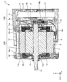
- FIG. 2 is a sectional view taken along line II-II of FIG.
- the motor assembly 1 includes a motor 2, a resolver 3, an inverter 4, and a housing 5.
- the housing 5 has a motor housing 6 and a circuit housing 7.
- the motor housing 6 and the circuit housing 7 are manufactured by casting, for example.
- the motor housing 6 is an example of the first housing, and is an example of a cylindrical main body portion 6a having one side and the other side open in the axial direction (Z direction) and one side of the main body portion 6a which is the load side of the motor 2. It has a lid portion 6b that closes the opening.
- the motor housing 6 has a bottomed tubular internal space that is open on the other side in the axial direction as a whole, and the motor 2 is housed in the internal space.
- the internal space on the side where the motor 2 is arranged is also referred to as a first space.
- FIG. 3 is a view (front view) of the motor housing 6 as viewed from the other side.
- the motor 2 arranged in the motor housing 6 includes a stator 11 in which a coil is wound, a rotor 12 in which a permanent magnet (not shown) is arranged, and a motor shaft 13 which is a rotation shaft of the motor 2.
- the motor 2 of the present embodiment is an inner rotor type motor, and the stator 11 is arranged on the outer periphery of the rotor 12 with a slight air gap.
- the motor shaft 13 is fitted into the iron core of the rotor 12 along the axial direction, and is rotatably supported by bearings 14a and 14b arranged on the load side and the counterload side. Further, one side of the motor shaft 13 on the load side is projected to the outside of the housing 5 through the lid portion 6b of the motor housing 6.
- the main body 6a of the motor housing 6 has a first oil passage 15 through which cooling oil for cooling the coil of the motor 2 is circulated, and two second oil passages 16 connected to the first oil passage 15. doing.
- the first oil passage 15 is arranged on the upper side in FIG. 2 with respect to the motor 2, and extends in the axial direction.
- Each of the second oil passages 16 is connected to both ends of the first oil passage 15, and both extend in the circumferential direction of the motor 2 at the position of the coil end 11a of the stator 11 (see FIG. 3).
- a plurality of discharge ports 16a for discharging cooling oil into the internal space of the motor housing 6 are formed on the lower surface of the second oil passage 16.
- the region B near the bottom surface located on the lower side in FIG. 2 functions as an oil pan for storing cooling oil.
- the cooling oil is supplied to the first oil passage 15 from the oil pan on the bottom surface side by driving an oil pump (not shown).
- the cooling oil supplied to the first oil passage 15 flows into the second oil passage 16, and the cooling oil is discharged from the discharge port 16a of the second oil passage 16 toward the coil end 11a of the stator 11.
- the cooling oil that comes into contact with the coil end 11a of the stator 11 removes heat from the coil, and then drops and stores the cooling oil in the oil pan. As described above, the coil of the stator 11 is cooled by the cooling oil.
- the resolver 3 is a detector that detects the rotation angle of the motor shaft 13 in the motor 2, and is attached to the counterload side of the motor shaft 13. It is also possible to detect the speed of the vehicle by obtaining the rotation angle per hour from the output of the resolver 3.
- the resolver 3 is connected to the inverter 4 via a signal line.
- the circuit housing 7 is an example of the second housing, and has a box-shaped main body portion 8 having an opening on the other side in the axial direction, and a lid portion 9 covering the opening surface on the other side of the main body portion 8.
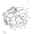
- FIG. 4 is a perspective view showing a state in which the lid portion 9 of the circuit housing 7 and the inverter 4 are removed in the motor assembly 1.
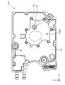
- FIG. 5 is a front view of FIG.
- the circuit housing 7 is attached to the other side of the motor housing 6 which is the opposite load side of the motor 2. Further, the circuit housing 7 accommodates the inverter 4 inside the circuit housing 7. In the housing 5, the internal space on the side where the inverter 4 is arranged is also referred to as a second space.
- main wall 8a of the main body 8 of the circuit housing 7 facing the other side of the motor housing 6 not only partitions the inside and the outside of the circuit housing 7, but also the other side of the motor housing 6 when the housing 5 is in the assembled state. It also has the function of closing the opening on the side.
- the inverter 4 is a controller for controlling the motor 2.
- the inverter 4 includes elements such as a high-speed switching element (such as an IGBT), a gate substrate, a capacitor, a discharge resistor, and a control substrate.
- the inverter 4 has a function of converting a DC voltage from a battery (not shown) into an alternating current and supplying it to the coil of the motor 2 at the time of power running, and converting an alternating current from the motor 2 into a direct current to the battery at the time of regeneration.
- a sensor arranging portion 8b is provided on the main wall 8a of the main body portion 8 of the circuit housing 7 with the position of the motor shaft 13 as the center.
- a cover receiver 8c that rises toward the other side is formed in an annular shape (see FIG. 5).
- a sensor cover 17 that covers the entire surface of the sensor arrangement portion 8b from the other side is attached to the cover receiver 8c.
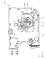
- FIG. 6 is a diagram showing a state in which the sensor cover 17 of FIG. 5 is removed.
- a resolver 3 is attached to the inside of the sensor arrangement portion 8b so as to face the sensor cover 17.
- a part of the sensor arrangement portion 8b is cut out to form an opening 8d.
- the sensor arranging unit 8b relays the signal line 19 of the thermistor from the motor housing 6 side to the inverter 4 through the opening 8d.
- the space of the sensor arranging portion 8b is in a state of being communicated with the internal space of the motor housing 6 by the opening 8d.
- the sensor arranging portion 8b is closed from the other side by the sensor cover 17 attached to the annular cover receiver 8c.
- the first space and the second space are separated from the main wall 8a of the main body 8 of the circuit housing 7 by the sensor cover 17.
- the main wall 8a and the sensor cover 17 of the main body 8 are examples of partition walls that partition the first space and the second space between the motor 2 and the inverter 4.
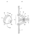
- the sensor cover 17 is provided with an opening 17a for passing the signal line 18 of the resolver 3 and the signal line 19 of the thermistor from the sensor arrangement portion 8b to the inverter 4 side.
- a grommet 20 with a film as a sealing member that closes the gap between the signal lines 18 and 19 and the opening 17a is arranged.
- FIG. 7 (A) is a perspective view of the grommet 20 with a film
- FIG. 7 (B) is a sectional view taken along line VIIb-VIIb of FIG. 7 (A).
- the grommet 20 with a film is integrally formed of an oil-resistant and elastically deformable resin material such as rubber, elastomer, and plastic.
- the grommet 20 with a film has a cylindrical portion 21 mounted on the opening 17a of the sensor cover 17 and a film portion 22 that closes the central side of the cylindrical portion 21.
- An annular groove 21a is formed on the outer circumference of the cylindrical portion 21 along the circumferential direction.
- the grommet 20 with a film is attached to the opening 17a of the sensor cover 17, the inner peripheral edge of the opening 17a is received inside the groove 21a.
- the grommet 20 with a film is prevented from coming off from the sensor cover 17, and oil enters the second space from the outer periphery of the cylindrical portion 21. Can be deterred.
- a plurality of holes 22a for passing signal lines 18 and 19 are formed in the film portion 22 along the axial direction of the cylindrical portion 21.
- the holes 22a of the film portion 22 are provided according to the number of signal lines 18 and 19, and one signal line is inserted into each of the holes 22a.
- each hole 22a is provided with an annular step portion 22b protruding toward the inner peripheral side. Therefore, in a state where the signal lines 18 and 19 are inserted into the holes 22a, the gap between the signal lines 18 and 19 and the holes 22a is sealed by the step portion 22b, and oil enters the second space from the holes 22a of the film portion 22. Can be deterred.
- the circuit housing 7 is arranged so as to face the opposite load side of the motor housing 6.
- the first space formed by the motor housing 6 and the second space formed by the circuit housing 7 are separated by partition walls (8a, 17) located between the motor 2 and the inverter 4, and the first space is divided.
- the space and the second space share a partition. Therefore, the motor assembly 1 can be downsized and the manufacturing cost can be reduced as compared with the configuration in which the motor housing 6 and the circuit housing 7 are not integrated.
- the circuit housing 7 can have the function of a partition wall, and the configuration of the housing 5 can be made simpler. can.
- the motor 2 and the resolver 3 are housed in the first space.
- the resolver 3 in the second space accommodating the inverter 4, it is necessary to insert the end of the motor shaft 13 connected to the resolver 3 into the circuit housing 7 and seal the gap with the circuit housing 7. Occurs.
- the sealing structure with the motor shaft 13 as described above is not required in the second space, so that the manufacturing cost of the motor assembly 1 can be suppressed.
- an opening 17a is provided in the partition wall portion that separates the first space and the second space, and the signal line 18 that connects the inverter 4 and the resolver 3 is inserted.
- a grommet 20 with a film that closes the gap between the signal line 18 and the opening 17a is attached to the opening 17a. Therefore, the harness of the inverter 4 in the second space and the harness of the resolver 3 in the first space can be connected, and the grommet 20 with a film suppresses the intrusion of oil from the opening 17a of the partition wall into the second space.
- NS For example, when the coil of the motor 2 is oil-cooled, the first space has an atmosphere containing oil mist, oil droplets, etc. of the cooling oil, but according to the present embodiment, the inverter 4 is separated from the cooling oil in the first space. Can be sealed.
- the motor assembly of the present invention is not limited to the electric vehicle, and may be used for other purposes.
- the configuration in which the coil is oil-cooled in the motor assembly has been described, but in the present invention, the coil of the motor may not be oil-cooled.
- the configuration of the present invention can also be applied when the inverter is sealed from the lubricating oil of the motor in the first space.
Landscapes
- Engineering & Computer Science (AREA)
- Power Engineering (AREA)
- Microelectronics & Electronic Packaging (AREA)
- Motor Or Generator Frames (AREA)
Abstract
モータ組立体は、モータを収容する第1の空間を形成する第1ハウジングと、モータを制御するインバータを収容する第2の空間を形成する第2ハウジングと、モータとインバータの間で第1の空間と第2の空間を仕切る隔壁部と、を備える。第2ハウジングは、モータの回転軸の反負荷側に臨むように第1ハウジングに取り付けられる。第1の空間に、モータの回転角を検出するレゾルバがさらに収容される。隔壁部は、インバータとレゾルバを接続する第1の信号線を挿通させる開口を有し、開口に、第1の信号線と開口の隙間を塞ぐシール部材が配置される。
Description
本発明は、モータ組立体に関する。
近年、環境負荷低減の観点から、EV,HEV,PHEV,FCV等のように動力源としてモータを搭載した電動車両の開発や普及が進んでいる。
電動車両用のモータにおいては、車両の組立作業性の向上や省スペース化のために、モータと当該モータを制御するためのインバータ回路を一体化し、モジュール化されたモータ組立体とすることが提案されている。また、電動車両用のモータでは、冷却効率を高めるために、コイルを冷却油で冷却する構成が採用されることもある。
この種のモータ組立体において、モータ組立体の小型化や製造コストの抑制のためには、インバータとモータの筐体をできるだけ一体化することが好ましい。しかし、インバータはコイルの冷却油やモータの潤滑油などから確実にシールされる必要があるので、モータ組立体の筐体の構成やオイルシールの配置などにはさらなる工夫が求められている。
例えば、モータの回転軸にはモータの回転位置を検出するレゾルバが設けられ、当該レゾルバのハーネスはインバータに接続される。上記のインバータとレゾルバのハーネスの接続では、筐体やオイルシールの構成を簡素化しつつ、モータ側の油からインバータをシールすることが要望される。
本発明は、上記の状況に鑑みてなされたものであって、モータ側の油からインバータをシールしつつインバータとレゾルバのハーネスを接続でき、かつ小型化や製造コストの抑制を図ることのできるモータ組立体を提供する。
本発明の一態様であるモータ組立体は、モータを収容する第1の空間を形成する第1ハウジングと、モータを制御するインバータを収容する第2の空間を形成する第2ハウジングと、モータとインバータの間で第1の空間と第2の空間を仕切る隔壁部と、を備える。第2ハウジングは、モータの回転軸の反負荷側に臨むように第1ハウジングに取り付けられる。第1の空間に、モータの回転角を検出するレゾルバがさらに収容される。隔壁部は、インバータとレゾルバを接続する第1の信号線を挿通させる開口を有し、開口に、第1の信号線と開口の隙間を塞ぐシール部材が配置される。
上記のモータ組立体において、レゾルバは、モータの回転軸の反負荷側に設けられ、隔壁部に対向して配置されてもよい。
上記のモータ組立体において、第1の空間においてモータのコイルは、冷却油で冷却されてもよい。
上記のモータ組立体において、開口には、モータの温度を検知するサーミスタからの第2の信号線がさらに挿通されてもよい。また、シール部材は、第2の信号線と開口の隙間を塞いでもよい。
上記のモータ組立体において、第1の空間においてモータのコイルは、冷却油で冷却されてもよい。
上記のモータ組立体において、開口には、モータの温度を検知するサーミスタからの第2の信号線がさらに挿通されてもよい。また、シール部材は、第2の信号線と開口の隙間を塞いでもよい。
本発明の一態様のモータ組立体によれば、モータ側の油からインバータをシールしつつインバータとレゾルバのハーネスを接続でき、かつモータ組立体の小型化や製造コストの抑制を図ることができる。
以下、本発明の実施形態について図面を参照して説明する。
実施形態では説明を分かり易くするため、本発明の主要部以外の構造や要素については、簡略化または省略して説明する。また、図面において、同じ要素には同じ符号を付す。なお、図面に示す各要素の形状、寸法などは模式的に示したもので、実際の形状、寸法などを示すものではない。
実施形態では説明を分かり易くするため、本発明の主要部以外の構造や要素については、簡略化または省略して説明する。また、図面において、同じ要素には同じ符号を付す。なお、図面に示す各要素の形状、寸法などは模式的に示したもので、実際の形状、寸法などを示すものではない。
また、図面においては、適宜3次元直交座標系としてXYZ座標系を示す。XYZ座標系において、Z方向はモータの回転軸の延長方向(軸方向)と平行な方向とする。X方向は、Z方向と直交する方向であって、図2の紙面奥行方向に対応する。Y方向は、X方向とZ方向との両方と直交する方向であって、図2の上下方向に対応する。
図1は、本実施形態の電動車両用のモータ組立体1の一例を示す斜視図である。図2は、図1のII-II線断面図である。
モータ組立体1は、モータ2と、レゾルバ3と、インバータ4と、筐体5とを備えている。筐体5は、モータハウジング6と、回路ハウジング7を有する。なお、モータハウジング6および回路ハウジング7は、例えば鋳造によって製造される。
モータハウジング6は、第1ハウジングの一例であって、軸方向(Z方向)の一方側および他方側が開口した筒状の本体部6aと、モータ2の負荷側となる本体部6aの一方側の開口を塞ぐ蓋部6bを有する。モータハウジング6は、軸方向の他方側が開口した有底筒状の内部空間を全体として有し、モータ2はその内部空間に収容される。筐体5において、モータ2が配置されている側の内部空間を第1の空間とも称する。
また、図3は、モータハウジング6を他方側から見た図(正面図)である。
また、図3は、モータハウジング6を他方側から見た図(正面図)である。
モータハウジング6に配置されるモータ2は、コイルが巻回されたステータ11と、永久磁石(不図示)が配置されたロータ12と、モータ2の回転軸であるモータシャフト13と、を備える。本実施形態のモータ2はインナーロータ型のモータであって、ロータ12の外周には僅かなエアギャップを隔ててステータ11が配置される。モータシャフト13は、軸方向に沿ってロータ12の鉄心に嵌入されており、負荷側および反負荷側に配置された軸受14a、14bにより回転自在に支持されている。また、モータシャフト13の負荷側である一方側は、モータハウジング6の蓋部6bを挿通して筐体5の外側に突出している。
モータ2においては、コイルの電流制御によりステータ11の磁界を順番に切り替えることで、ロータ12の磁界との吸引力または反発力が生じる。これにより、ロータ12およびモータシャフト13が回転する。なお、モータ組立体1を電動車両に搭載したときには、モータシャフト13の負荷側に減速機構およびドライブシャフト(いずれも不図示)が接続される。
また、モータハウジング6の本体部6aは、モータ2のコイルを冷却するための冷却油を流通させる第1油路15と、第1油路15に接続される2つの第2油路16を有している。図2に示すように、第1油路15は、モータ2よりも図2中上側に配置され、軸方向に延長している。各々の第2油路16は、第1油路15の両端部にそれぞれ接続され、いずれもステータ11のコイルエンド11aの位置においてモータ2の周方向に延長している(図3参照)。また、第2油路16の下面には、モータハウジング6の内部空間に冷却油を吐出する複数の吐出口16aが形成されている。
また、モータハウジング6の内部空間において、図2中下側に位置する底面近傍の領域Bは、冷却油を貯留するオイルパンとして機能する。冷却油は、オイルポンプ(不図示)の駆動によって底面側のオイルパンから第1油路15に供給される。第1油路15に供給された冷却油は第2油路16に流入し、第2油路16の吐出口16aからステータ11のコイルエンド11aに向けて冷却油が吐出される。ステータ11のコイルエンド11aに接触した冷却油はコイルから熱を奪い、その後に滴下してオイルパンに貯留される。以上のようにして、ステータ11のコイルは冷却油で冷却される。
レゾルバ3は、モータ2におけるモータシャフト13の回転角を検出する検出器であり、モータシャフト13の反負荷側に取り付けられている。レゾルバ3の出力から時間当たりの回転角を求めることで、車両の速度を検出することも可能である。なお、レゾルバ3は信号線を介してインバータ4と接続される。
回路ハウジング7は、第2ハウジングの一例であって、軸方向の他方側が開口された箱体状の本体部8と、本体部8の他方側の開口面を覆う蓋部9とを有する。
図4は、モータ組立体1において、回路ハウジング7の蓋部9およびインバータ4を外した状態を示す斜視図である。図5は、図4の正面図である。
図4は、モータ組立体1において、回路ハウジング7の蓋部9およびインバータ4を外した状態を示す斜視図である。図5は、図4の正面図である。
回路ハウジング7は、モータ2の反負荷側となるモータハウジング6の他方側に取り付けられる。また、回路ハウジング7は、インバータ4をその内部に収容する。なお、筐体5において、インバータ4が配置されている側の内部空間を第2の空間とも称する。
また、回路ハウジング7の本体部8においてモータハウジング6の他方側に臨む主壁8aは、回路ハウジング7の内部と外部を仕切るだけでなく、筐体5の組立状態のときにモータハウジング6の他方側の開口部分を塞ぐ機能も担う。
インバータ4は、モータ2を制御するためのコントローラである。インバータ4は、例えば、高速スイッチング素子(IGBTなど)、ゲート基板、コンデンサ、放電抵抗および制御基板などの要素を含む。インバータ4は、力行時にはバッテリ(不図示)からの直流電圧を交流に変換してモータ2のコイルに供給し、回生時にはモータ2からの交流をバッテリへの直流に変換する機能を担う。
また、回路ハウジング7の本体部8の主壁8aには、モータシャフト13の位置を中心としてセンサ配置部8bが設けられている。センサ配置部8bの周囲には、他方側に向けて隆起するカバー受け8cが環状に形成されている(図5参照)。このカバー受け8cには、センサ配置部8bの全面を他方側から覆うセンサカバー17が取り付けられる。
図6は、図5のセンサカバー17を外した状態を示す図である。
センサ配置部8bの内側には、センサカバー17と対向するようにレゾルバ3が取り付けられる。また、ステータ11のコイルの温度を検知するサーミスタ(不図示)からの信号線19をセンサ配置部8bに通すために、センサ配置部8bの一部は切り欠かれて開口部8dが形成されている。このように、センサ配置部8bは、開口部8dを介してサーミスタの信号線19をモータハウジング6側からインバータ4に中継する。
センサ配置部8bの内側には、センサカバー17と対向するようにレゾルバ3が取り付けられる。また、ステータ11のコイルの温度を検知するサーミスタ(不図示)からの信号線19をセンサ配置部8bに通すために、センサ配置部8bの一部は切り欠かれて開口部8dが形成されている。このように、センサ配置部8bは、開口部8dを介してサーミスタの信号線19をモータハウジング6側からインバータ4に中継する。
センサ配置部8bの空間は、開口部8dによりモータハウジング6の内部空間と連通した状態となる。一方、センサ配置部8bは、環状のカバー受け8cに取り付けられたセンサカバー17によって他方側から塞がれる。これにより、第1の空間と第2の空間は、回路ハウジング7における本体部8の主壁8aとセンサカバー17によって仕切られる。本体部8の主壁8aおよびセンサカバー17は、モータ2とインバータ4の間で第1の空間と第2の空間を仕切る隔壁部の一例である。
また、センサカバー17には、センサ配置部8bからレゾルバ3の信号線18とサーミスタの信号線19をインバータ4側に通すための開口17aが設けられている。開口17aには、信号線18、19と開口17aとの隙間を塞ぐシール部材としての膜付きグロメット20が配置されている。
図7(A)は、膜付きグロメット20の斜視図であり、図7(B)は、図7(A)のVIIb-VIIb線断面図である。
膜付きグロメット20は、例えば、ゴムやエラストマ、プラスチック等のように、耐油性を有するとともに弾性変形可能な樹脂材料で一体形成されている。膜付きグロメット20は、センサカバー17の開口17aに装着される円筒部21と、円筒部21の中心側を塞ぐ膜部22を有している。
膜付きグロメット20は、例えば、ゴムやエラストマ、プラスチック等のように、耐油性を有するとともに弾性変形可能な樹脂材料で一体形成されている。膜付きグロメット20は、センサカバー17の開口17aに装着される円筒部21と、円筒部21の中心側を塞ぐ膜部22を有している。
円筒部21の外周には周方向に沿って環状の溝21aが形成されている。センサカバー17の開口17aに膜付きグロメット20が装着された状態において、溝21aの内部には開口17aの内周縁が受容される。膜付きグロメット20の溝21aに開口17aの内周縁が受容されることで、膜付きグロメット20がセンサカバー17から抜け止めされるとともに、円筒部21の外周から第2の空間に油が侵入することを抑止できる。
膜部22には、円筒部21の軸方向に沿って信号線18、19を通すための孔22aが複数形成されている。膜部22の孔22aは信号線18、19の数に応じて設けられ、各々の孔22aには信号線が一本ずつ挿入される。また、各々の孔22aには、内周側に突出する環状の段差部22bが設けられている。そのため、信号線18、19を孔22aに挿通した状態において、信号線18、19と孔22aの隙間が段差部22bによってシールされ、膜部22の孔22aから第2の空間に油が侵入することを抑止できる。
以下、本実施形態の効果を述べる。
本実施形態では、モータハウジング6の反負荷側に臨むように回路ハウジング7が配置される。モータハウジング6により形成される第1の空間と、回路ハウジング7により形成される第2の空間は、モータ2とインバータ4の間に位置する隔壁部(8a、17)で仕切られ、第1の空間と第2の空間は隔壁部を共有する。そのため、モータハウジング6と回路ハウジング7を一体化しない構成と比べて、モータ組立体1の小型化や製造コストの低減を図ることができる。また、回路ハウジング7の主壁8aでモータハウジング6の他方側の開口を塞ぐ構成とすることで、回路ハウジング7に隔壁部の機能を持たせることができ、筐体5の構成をより簡素にできる。
本実施形態では、モータハウジング6の反負荷側に臨むように回路ハウジング7が配置される。モータハウジング6により形成される第1の空間と、回路ハウジング7により形成される第2の空間は、モータ2とインバータ4の間に位置する隔壁部(8a、17)で仕切られ、第1の空間と第2の空間は隔壁部を共有する。そのため、モータハウジング6と回路ハウジング7を一体化しない構成と比べて、モータ組立体1の小型化や製造コストの低減を図ることができる。また、回路ハウジング7の主壁8aでモータハウジング6の他方側の開口を塞ぐ構成とすることで、回路ハウジング7に隔壁部の機能を持たせることができ、筐体5の構成をより簡素にできる。
また、本実施形態では、第1の空間にモータ2とレゾルバ3が収容される。インバータ4を収容する第2の空間にレゾルバ3を配置する場合、レゾルバ3に接続されるモータシャフト13の端部を回路ハウジング7内に挿通させるとともに、回路ハウジング7との隙間をシールする必要が生じる。しかし、本実施形態では、第2の空間において上記のようなモータシャフト13とのシール構造は不要となるので、モータ組立体1の製造コストを抑制できる。
また、本実施形態では、第1の空間と第2の空間を仕切る隔壁部に開口17aを設けてインバータ4とレゾルバ3を接続する信号線18を挿通させる。上記の開口17aには、信号線18と開口17aの隙間を塞ぐ膜付きグロメット20が装着される。そのため、第2の空間のインバータ4と第1の空間のレゾルバ3のハーネスの接続を可能にするとともに、膜付きグロメット20によって隔壁部の開口17aから第2の空間への油の侵入が抑止される。例えば、モータ2のコイルを油冷する場合、第1の空間は冷却油のオイルミストや油滴等を含む雰囲気となるが、本実施形態によればインバータ4を第1の空間の冷却油からシールできる。
本発明は、上記実施形態に限定されることなく、本発明の趣旨を逸脱しない範囲において、種々の改良並びに設計の変更を行ってもよい。
上記実施形態においては、モータ組立体が電動車両に搭載される場合について説明した。しかし、本発明のモータ組立体は電動車両用に限定されるものではなく、他の用途に使用されるものであってもよい。
また、上記実施形態では、モータ組立体においてコイルを油冷する構成について説明したが、本発明においてモータのコイルは油冷されていなくてもよい。例えば、第1の空間におけるモータの潤滑油からインバータをシールする場合にも本発明の構成を適用することができる。
また、上記実施形態では、モータ組立体においてコイルを油冷する構成について説明したが、本発明においてモータのコイルは油冷されていなくてもよい。例えば、第1の空間におけるモータの潤滑油からインバータをシールする場合にも本発明の構成を適用することができる。
加えて、今回開示された実施形態は、全ての点で例示であって制限的なものではないと考えられるべきである。本発明の範囲は、上記した説明ではなくて特許請求の範囲によって示され、特許請求の範囲と均等の意味及び範囲内での全ての変更が含まれることが意図される。
1…モータ組立体、2…モータ、3…レゾルバ、4…インバータ、5…筐体、6…モータハウジング、7…回路ハウジング、8…本体部、8a…主壁、8b…センサ配置部、9…蓋部、11…ステータ、12…ロータ、13…モータシャフト、17…センサカバー、17a…開口、18,19…信号線、20…膜付きグロメット
Claims (4)
- モータを収容する第1の空間を形成する第1ハウジングと、
前記モータを制御するインバータを収容する第2の空間を形成する第2ハウジングと、
前記モータと前記インバータの間で前記第1の空間と前記第2の空間を仕切る隔壁部と、を備え、
前記第2ハウジングは、前記モータの回転軸の反負荷側に臨むように前記第1ハウジングに取り付けられ、
前記第1の空間に、前記モータの回転角を検出するレゾルバがさらに収容され、
前記隔壁部は、前記インバータと前記レゾルバを接続する第1の信号線を挿通させる開口を有し、
前記開口に、前記第1の信号線と前記開口の隙間を塞ぐシール部材が配置される
ことを特徴とするモータ組立体。 - 前記レゾルバは、前記モータの回転軸の反負荷側に設けられ、前記隔壁部に対向して配置される
ことを特徴とする請求項1に記載のモータ組立体。 - 前記第1の空間において前記モータのコイルは、冷却油で冷却される
ことを特徴とする請求項1または請求項2に記載のモータ組立体。 - 前記開口には、前記モータの温度を検知するサーミスタからの第2の信号線がさらに挿通され、
前記シール部材は、前記第2の信号線と前記開口の隙間を塞ぐ
ことを特徴とする請求項1から請求項3のいずれか一項に記載のモータ組立体。
Applications Claiming Priority (2)
| Application Number | Priority Date | Filing Date | Title |
|---|---|---|---|
| JP2020047602A JP6977803B2 (ja) | 2020-03-18 | 2020-03-18 | モータ組立体 |
| JP2020-047602 | 2020-03-18 |
Publications (1)
| Publication Number | Publication Date |
|---|---|
| WO2021187203A1 true WO2021187203A1 (ja) | 2021-09-23 |
Family
ID=77771258
Family Applications (1)
| Application Number | Title | Priority Date | Filing Date |
|---|---|---|---|
| PCT/JP2021/009069 Ceased WO2021187203A1 (ja) | 2020-03-18 | 2021-03-08 | モータ組立体 |
Country Status (2)
| Country | Link |
|---|---|
| JP (1) | JP6977803B2 (ja) |
| WO (1) | WO2021187203A1 (ja) |
Cited By (1)
| Publication number | Priority date | Publication date | Assignee | Title |
|---|---|---|---|---|
| JPWO2025192263A1 (ja) * | 2024-03-13 | 2025-09-18 |
Citations (5)
| Publication number | Priority date | Publication date | Assignee | Title |
|---|---|---|---|---|
| JPH01171563U (ja) * | 1988-05-18 | 1989-12-05 | ||
| JP2005076730A (ja) * | 2003-08-29 | 2005-03-24 | Koyo Seiko Co Ltd | 転がり軸受装置 |
| JP2008211945A (ja) * | 2007-02-28 | 2008-09-11 | Hitachi Ltd | 車両駆動装置 |
| JP2015202049A (ja) * | 2015-06-30 | 2015-11-12 | 三菱電機株式会社 | 電動駆動装置 |
| JP2018121422A (ja) * | 2017-01-24 | 2018-08-02 | トヨタ自動車株式会社 | 回転電機の冷却構造 |
Family Cites Families (2)
| Publication number | Priority date | Publication date | Assignee | Title |
|---|---|---|---|---|
| JP5409055B2 (ja) * | 2009-03-10 | 2014-02-05 | 三菱重工業株式会社 | インバータ一体型電動圧縮機 |
| JP2011185294A (ja) * | 2010-03-04 | 2011-09-22 | Yazaki Corp | シール部材及びシール構造 |
-
2020
- 2020-03-18 JP JP2020047602A patent/JP6977803B2/ja active Active
-
2021
- 2021-03-08 WO PCT/JP2021/009069 patent/WO2021187203A1/ja not_active Ceased
Patent Citations (5)
| Publication number | Priority date | Publication date | Assignee | Title |
|---|---|---|---|---|
| JPH01171563U (ja) * | 1988-05-18 | 1989-12-05 | ||
| JP2005076730A (ja) * | 2003-08-29 | 2005-03-24 | Koyo Seiko Co Ltd | 転がり軸受装置 |
| JP2008211945A (ja) * | 2007-02-28 | 2008-09-11 | Hitachi Ltd | 車両駆動装置 |
| JP2015202049A (ja) * | 2015-06-30 | 2015-11-12 | 三菱電機株式会社 | 電動駆動装置 |
| JP2018121422A (ja) * | 2017-01-24 | 2018-08-02 | トヨタ自動車株式会社 | 回転電機の冷却構造 |
Cited By (2)
| Publication number | Priority date | Publication date | Assignee | Title |
|---|---|---|---|---|
| JPWO2025192263A1 (ja) * | 2024-03-13 | 2025-09-18 | ||
| WO2025192263A1 (ja) * | 2024-03-13 | 2025-09-18 | 株式会社明電舎 | 回転電機組立体 |
Also Published As
| Publication number | Publication date |
|---|---|
| JP2021151050A (ja) | 2021-09-27 |
| JP6977803B2 (ja) | 2021-12-08 |
Similar Documents
| Publication | Publication Date | Title |
|---|---|---|
| US12101003B2 (en) | Motor with inverter and bus bar arrangement | |
| JP4265571B2 (ja) | 車両用交流発電機 | |
| JP4949983B2 (ja) | 回転電機 | |
| JP4479799B2 (ja) | 車両用交流発電機 | |
| JP6462313B2 (ja) | 駆動装置 | |
| CN111213305B (zh) | 驱动装置 | |
| US20140191623A1 (en) | Breathing electric motor | |
| CN104995825A (zh) | 用于车辆和铁路车辆的电动机 | |
| CN110999040A (zh) | 马达 | |
| JP6870989B2 (ja) | ロータおよび電動モータ | |
| US20130193787A1 (en) | Motor and brushless motor | |
| JP6977803B2 (ja) | モータ組立体 | |
| US6809454B2 (en) | Motor having brush holder with communication hole | |
| JP6435972B2 (ja) | 動力伝達装置 | |
| JP7482023B2 (ja) | 液冷式電動モータ | |
| JP2017093184A (ja) | 車両用回転電機 | |
| JP2013217237A (ja) | 電動オイルポンプ装置 | |
| CN118489203B (zh) | 旋转机 | |
| JP7484759B2 (ja) | モータ組立体の隔壁構造 | |
| JP7578149B2 (ja) | 回転電機の筐体構造 | |
| JP2006280088A (ja) | ブラシレスモータ | |
| JP3785964B2 (ja) | 車両用交流発電機 | |
| KR20180080537A (ko) | 모터의 하우징 및 이를 포함하는 모터 | |
| JP2010156224A (ja) | 電動ポンプ | |
| JP2019170040A (ja) | 減速機付きモータ |
Legal Events
| Date | Code | Title | Description |
|---|---|---|---|
| 121 | Ep: the epo has been informed by wipo that ep was designated in this application |
Ref document number: 21771714 Country of ref document: EP Kind code of ref document: A1 |
|
| NENP | Non-entry into the national phase |
Ref country code: DE |
|
| 122 | Ep: pct application non-entry in european phase |
Ref document number: 21771714 Country of ref document: EP Kind code of ref document: A1 |