WO2021187054A1 - 電線保護部材及びワイヤハーネス - Google Patents
電線保護部材及びワイヤハーネス Download PDFInfo
- Publication number
- WO2021187054A1 WO2021187054A1 PCT/JP2021/007319 JP2021007319W WO2021187054A1 WO 2021187054 A1 WO2021187054 A1 WO 2021187054A1 JP 2021007319 W JP2021007319 W JP 2021007319W WO 2021187054 A1 WO2021187054 A1 WO 2021187054A1
- Authority
- WO
- WIPO (PCT)
- Prior art keywords
- electric wire
- case
- magnetic core
- exterior member
- core
- Prior art date
- Legal status (The legal status is an assumption and is not a legal conclusion. Google has not performed a legal analysis and makes no representation as to the accuracy of the status listed.)
- Ceased
Links
Images


Classifications
-
- H—ELECTRICITY
- H02—GENERATION; CONVERSION OR DISTRIBUTION OF ELECTRIC POWER
- H02G—INSTALLATION OF ELECTRIC CABLES OR LINES, OR OF COMBINED OPTICAL AND ELECTRIC CABLES OR LINES
- H02G3/00—Installations of electric cables or lines or protective tubing therefor in or on buildings, equivalent structures or vehicles
- H02G3/02—Details
- H02G3/04—Protective tubing or conduits, e.g. cable ladders or cable troughs
- H02G3/0406—Details thereof
-
- B—PERFORMING OPERATIONS; TRANSPORTING
- B60—VEHICLES IN GENERAL
- B60R—VEHICLES, VEHICLE FITTINGS, OR VEHICLE PARTS, NOT OTHERWISE PROVIDED FOR
- B60R16/00—Electric or fluid circuits specially adapted for vehicles and not otherwise provided for; Arrangement of elements of electric or fluid circuits specially adapted for vehicles and not otherwise provided for
- B60R16/02—Electric or fluid circuits specially adapted for vehicles and not otherwise provided for; Arrangement of elements of electric or fluid circuits specially adapted for vehicles and not otherwise provided for electric constitutive elements
- B60R16/0207—Wire harnesses
- B60R16/0215—Protecting, fastening and routing means therefor
-
- H—ELECTRICITY
- H01—ELECTRIC ELEMENTS
- H01F—MAGNETS; INDUCTANCES; TRANSFORMERS; SELECTION OF MATERIALS FOR THEIR MAGNETIC PROPERTIES
- H01F17/00—Fixed inductances of the signal type
- H01F17/04—Fixed inductances of the signal type with magnetic core
- H01F17/06—Fixed inductances of the signal type with magnetic core with core substantially closed in itself, e.g. toroid
-
- H—ELECTRICITY
- H01—ELECTRIC ELEMENTS
- H01F—MAGNETS; INDUCTANCES; TRANSFORMERS; SELECTION OF MATERIALS FOR THEIR MAGNETIC PROPERTIES
- H01F27/00—Details of transformers or inductances, in general
- H01F27/02—Casings
-
- H—ELECTRICITY
- H01—ELECTRIC ELEMENTS
- H01F—MAGNETS; INDUCTANCES; TRANSFORMERS; SELECTION OF MATERIALS FOR THEIR MAGNETIC PROPERTIES
- H01F7/00—Magnets
- H01F7/02—Permanent magnets [PM]
-
- H—ELECTRICITY
- H01—ELECTRIC ELEMENTS
- H01F—MAGNETS; INDUCTANCES; TRANSFORMERS; SELECTION OF MATERIALS FOR THEIR MAGNETIC PROPERTIES
- H01F17/00—Fixed inductances of the signal type
- H01F17/04—Fixed inductances of the signal type with magnetic core
- H01F17/06—Fixed inductances of the signal type with magnetic core with core substantially closed in itself, e.g. toroid
- H01F2017/065—Core mounted around conductor to absorb noise, e.g. EMI filter
-
- H—ELECTRICITY
- H02—GENERATION; CONVERSION OR DISTRIBUTION OF ELECTRIC POWER
- H02G—INSTALLATION OF ELECTRIC CABLES OR LINES, OR OF COMBINED OPTICAL AND ELECTRIC CABLES OR LINES
- H02G3/00—Installations of electric cables or lines or protective tubing therefor in or on buildings, equivalent structures or vehicles
- H02G3/02—Details
- H02G3/04—Protective tubing or conduits, e.g. cable ladders or cable troughs
- H02G3/0462—Tubings, i.e. having a closed section
- H02G3/0481—Tubings, i.e. having a closed section with a circular cross-section
Definitions
- This disclosure relates to a wire protection member and a wire harness.
- Patent Document 1 describes an electric wire protection member provided at an end portion of a cylindrical exterior member that covers the outer circumference of an electric wire in the length direction.
- the electric wire protection member includes a covering portion that covers an edge portion on the inner peripheral side at the end portion.
- the covering portion suppresses the electric wire from coming into contact with the edge portion when the lead-out portion of the electric wire pulled out from the end portion of the exterior member is routed or when the vehicle vibrates after assembly. Damage to the electric wire due to contact with the edge on the inner peripheral side is suppressed.
- Patent Document 2 describes an electromagnetic wave absorbing member for absorbing an electromagnetic wave (electromagnetic noise) radiated from an electric wire.
- the electromagnetic wave absorbing member has a case fixed to the electric wire so as to surround the outer periphery of the electric wire, and a magnetic core (sleeve core in Patent Document 2) housed in the case.
- the magnetic core is made of, for example, a ferrite core, and the electromagnetic wave radiated from the electric wire can be absorbed by the magnetic core.
- the lead-out portion of the electric wire comes into contact with the edge portion on the inner peripheral side due to the weight of the electromagnetic wave absorbing member. It will be easier to do. Therefore, in such a configuration, it is preferable to use the electric wire protection member as in Patent Document 1 together, but in this case, both the electromagnetic wave absorbing member including the case and the magnetic core and the electric wire protecting member are used. The provision causes a problem that the number of parts increases.
- An object of the present disclosure is to provide an electric wire protection member and a wire harness that can absorb electromagnetic waves radiated from an electric wire while suppressing an increase in the number of parts.
- the electric wire protection member of the present disclosure is an electric wire protection member provided at an end portion in the length direction of a tubular exterior member covering the outer circumference of the electric wire, and is magnetic provided so as to surround the case and the outer circumference of the electric wire.
- the case includes a body core, and the case integrally has a core accommodating portion for accommodating the magnetic core and a covering portion for covering an inner peripheral edge portion at the end portion.
- the wire harness of the present disclosure is a wire harness including an electric wire, a tubular exterior member covering the outer periphery of the electric wire, and an electric wire protection member provided at an end portion of the exterior member in the length direction.
- the electric wire protection member includes a case and a magnetic core provided so as to surround the outer periphery of the electric wire, and the case includes a core accommodating portion accommodating the magnetic core and the end. It integrally has a covering portion that covers the edge portion on the inner peripheral side of the portion.
- an electric wire protection member and a wire harness that can absorb electromagnetic waves radiated from an electric wire while suppressing an increase in the number of parts.
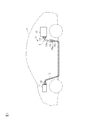
- FIG. 1 is a schematic configuration diagram showing a wire harness of an embodiment.
- FIG. 2 is a perspective view showing a main part of the wire harness of FIG.
- FIG. 3 is an exploded perspective view showing a main part of the wire harness of FIG.
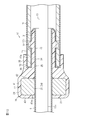
- FIG. 4 is a cross-sectional view showing a main part of the wire harness of FIG.
- FIG. 5 is a cross-sectional view showing a main part of the wire harness of the first modification.
- FIG. 6 is a cross-sectional view showing a main part of the wire harness of the second modification.
- FIG. 7 is a front view showing the electric wire protection member of the third modification example.
- FIG. 8 is a front view showing the electric wire protection member of the fourth modification example.
- FIG. 9 is a perspective view showing an exterior member of the fifth modification example.
- FIG. 10 is a cross-sectional view showing a main part of the wire harness of the sixth modification example.
- the electric wire protection member of the present disclosure is [1] An electric wire protection member provided at an end portion of a tubular exterior member covering the outer circumference of an electric wire in the length direction, and a case and a magnetic core provided so as to surround the outer circumference of the electric wire.
- the case integrally includes a core accommodating portion for accommodating the magnetic core and a covering portion for covering the inner peripheral edge portion at the end portion.
- a covering portion for preventing contact between the electric wire and the end portion of the exterior member and a core accommodating portion for accommodating the magnetic core are integrally provided in the case of the electric wire protection member.
- the case has a locking portion that is locked to the locked portion of the exterior member, and one of the locking portion and the locked portion is a convex portion, and the locking portion.
- the other side of the locked portion is a concave portion into which the convex portion is fitted.
- the case has an insertion portion to be inserted into the inner peripheral side or the outer peripheral side of the exterior member, and the insertion portion and the core accommodating portion are provided at positions where they do not overlap each other in the radial direction. .. According to this configuration, the core accommodating portion and the magnetic core can be arranged outside the exterior member.
- the magnetic core has a core-side through hole through which the electric wire is passed, the diameter of the core-side through hole is set to be smaller than the inner diameter of the end portion, and the magnetic core is the same.
- the corner portion defining the opening of the core side through hole has a core side chamfered portion chamfered in a curved surface shape. According to this configuration, it is possible to prevent the electric wire from being damaged by the electric wire coming into contact with the corner portion (core side surface portion) that defines the opening of the through hole on the core side.
- the case has a case-side through hole through which the electric wire is passed, and the diameter of the case-side through hole is set to be smaller than the inner diameter of the end of the exterior member. It has a case side chamfered portion in which the corner portion defining the opening of the case side through hole is chamfered in a curved surface shape. According to this configuration, it is possible to prevent the electric wire from being damaged by the electric wire coming into contact with the corner portion (case side surface portion) that defines the opening of the through hole on the case side.
- the covering portion includes an inner side wall portion in contact with an inner peripheral surface including the end portion of the exterior member, an outer wall portion in contact with an outer peripheral surface including the end portion of the exterior member, the inner side wall portion, and the inner side wall portion. It is a fitting portion having a bottom wall portion connecting the outer wall portions, and the end portion of the exterior member is fitted between the outer wall portion and the inner side wall portion in the fitting portion. .. According to this configuration, the end portion of the exterior member is fitted to the fitting portion of the case, so that the electric wire protection member can be firmly connected to the end portion of the exterior member.
- the wire harness of the present disclosure includes an electric wire, a tubular exterior member covering the outer periphery of the electric wire, and an electric wire protection member provided at an end portion of the exterior member in the length direction.
- the wire harness includes a case and a magnetic core provided so as to surround the outer periphery of the electric wire, and the case includes a core accommodating portion for accommodating the magnetic core. , And a covering portion that covers the inner peripheral side edge portion of the end portion.
- a covering portion for preventing contact between the electric wire and the end portion of the exterior member and a core accommodating portion for accommodating the magnetic core are integrally provided in the case of the electric wire protection member.
- the wire harness includes a connector provided at an end portion of the electric wire in the length direction, and the electric wire protection member and the connector are separated from each other in the length direction of the electric wire.
- the case of the electric wire protection member in a configuration in which the connector at the end of the electric wire is separated from the exterior member, can have a covering portion and a core accommodating portion integrally.
- the wire harness 10 shown in FIG. 1 electrically connects two or three or more electric devices provided in a vehicle V such as a hybrid vehicle or an electric vehicle.
- the wire harness 10 electrically connects, for example, the inverter 11 provided in the vehicle V and the high-voltage battery 12, respectively.
- the wire harness 10 is arranged so that, for example, the intermediate portion of the wire harness 10 in the length direction passes outside the vehicle interior such as under the floor of the vehicle V.
- the inverter 11 is connected to a wheel drive motor (not shown) that is a power source for traveling the vehicle.
- the inverter 11 generates AC power from the DC power of the high-voltage battery 12, and supplies the AC power to the motor.
- the high voltage battery 12 is, for example, a battery capable of supplying a voltage of several hundred volts.
- the wire harness 10 collectively surrounds, for example, one or a plurality of electric wires (three in the present embodiment), a pair of connectors 14 attached to both ends of the electric wires 13, and the plurality of electric wires 13. It includes an exterior member 15 and an electric wire protection member 16 provided at an end portion 15a of the exterior member 15 in the length direction.
- each electric wire 13 is connected to the inverter 11 via the connector 14, and the other end of each electric wire 13 is connected to the high voltage battery 12 via the connector 14.
- the electric wire 13 is formed in a long shape so as to extend in the front-rear direction of the vehicle V, for example. Further, the electric wire 13 is, for example, a high-voltage electric wire capable of dealing with a high voltage and a large current.
- the electric wire 13 may be, for example, a shielded electric wire having an electromagnetically shielded structure by itself, or a non-shielded electric wire having no electromagnetically shielded structure by itself. Alternatively, the outer circumference of the non-shielded electric wire may be covered with a separate shield member.
- Each electric wire 13 of this embodiment is a non-shielded electric wire.
- the electric wire 13 is a coated electric wire in which the core wire made of a conductor is coated with an insulating coating.
- the insulating coating of the electric wire 13 is made of an insulating material such as a synthetic resin.
- the core wire of the electric wire 13 is, for example, a stranded wire formed by twisting a plurality of metal strands, a columnar conductor made of one columnar metal rod having a solid structure inside, or a cylinder having a hollow structure inside. A shaped conductor or the like can be used. Further, as the core wire of the electric wire 13, for example, a stranded wire, a columnar conductor, or a tubular conductor may be used in combination. Examples of the columnar conductor include a single core wire and a bass bar.
- the core wire of the electric wire 13 of the present embodiment is a stranded wire.
- the cross-sectional shape (that is, the cross-sectional shape) obtained by cutting the core wire of the electric wire 13 along a plane orthogonal to the length direction of the core wire of the electric wire 13 includes a circular shape, a semicircular shape, a polygonal shape, a square shape, a flat shape, and the like. It can have any shape.
- the exterior member 15 has a long cylindrical shape as a whole.
- a plurality of electric wires 13 are inserted in the internal space of the exterior member 15.
- the exterior member 15 is formed so as to surround the outer periphery of the plurality of electric wires 13 over the entire circumference, for example.
- the exterior member 15 protects the electric wire 13 from, for example, flying objects and water droplets.
- the exterior member 15 is provided so as to surround a part of the electric wire 13 in the length direction.
- cylindrical shape in the present specification may be regarded as a cylindrical shape as a whole, and has a tubular shape by combining a plurality of parts, a notch in a part like a C shape, and the like. Including things.
- the exterior member 15 of the present embodiment is composed of one component.
- the exterior member 15 of the present embodiment is composed of, for example, a metal or resin pipe.
- a metal material such as copper-based or aluminum-based can be used.
- a synthetic resin such as polyolefin, polyamide, polyester, or ABS resin can be used.
- the electric wire 13 has a lead-out portion 13a led out from the end portion 15a (the right end portion in FIG. 1) in the length direction of the exterior member 15 to the outside of the exterior member 15. ing.
- the lead-out portion 13a is led out from the end portion 15a of the exterior member 15 by a predetermined length. That is, the end portion 15a of the exterior member 15 and the connector 14 provided at the tip end portion of the lead-out portion 13a are separated by a predetermined length in the length direction of the electric wire 13.
- the electric wire protection member 16 is provided at the end portion 15a of the exterior member 15.
- the electric wire protection member 16 of the present embodiment has a tubular shape that collectively surrounds the outer circumferences of the plurality of electric wires 13.
- the electric wire protection member 16 is provided at an intermediate portion in the length direction of the electric wire 13 when viewed as a whole of the wire harness 10. Further, the electric wire protection member 16 is provided at a distance from the connector 14 provided at the tip of the lead-out portion 13a in the length direction of the electric wire 13.
- the electric wire protection member 16 has an annular case 21 along the circumferential direction of the exterior member 15 and a magnetic core 22 housed in the case 21.
- the magnetic core 22 has, for example, a through hole 23 through which a plurality of electric wires 13 are inserted. That is, the through hole 23 penetrates the magnetic core 22 in the length direction of the electric wire 13. Further, the magnetic core 22 has an annular shape by having a through hole 23. The magnetic core 22 of the present embodiment is formed in an annular shape.
- the "ring” in the present specification includes a circular ring having a circular outer edge shape, an elliptical or oval ring having an outer edge shape, a polygonal ring having a polygonal outer edge shape, and a polygonal ring having a rounded outer edge shape.
- the outer edge shape consists of any closed shape connected by a straight line or a curved line.
- the "ring” has a shape having a through hole in a plan view, and the outer edge shape and the inner circumference shape of the through hole are the same shape, or the outer edge shape and the inner circumference shape of the through hole are different shapes. including.
- the "ring” includes a ring having a predetermined length extending along the penetrating direction of the through hole, and the length thereof does not matter. Further, the “ring” in the present specification may be regarded as a ring as a whole, and includes a C-shaped one having a notch or the like in a part thereof.
- the magnetic core 22 has, for example, a through hole 23 in a plan view seen from the length direction of the electric wire 13, and is formed in an annular shape having a predetermined length extending along the penetration direction of the through hole 23. ..
- the magnetic core 22 of the present embodiment is continuously formed over the entire circumference in the circumferential direction, and is formed in a closed ring shape. That is, the magnetic core 22 of the present embodiment is not formed with a slit extending along the length direction of the electric wire 13.
- the magnetic core 22 of the present embodiment is composed of one component.
- the magnetic core 22 is composed of one component, but a plurality of core materials may be combined to form an annular magnetic core 22.
- the magnetic core 22 may be formed in an annular shape by combining a pair of core materials having a semicircular cross section. According to this, the electric wire protection member 16 including the magnetic core 22 can be retrofitted to the electric wire 13 assembled to the vehicle V.
- the magnetic core 22 has a function of reducing electromagnetic waves (electromagnetic noise) radiated from the electric wire 13 by being arranged so as to face the electric wire 13 over the entire circumference of the electric wire 13 in the circumferential direction, for example.
- the magnetic core 22 absorbs an electromagnetic wave radiated from an electric wire 13 and converts the energy of the electromagnetic wave into heat energy. As a result, the adverse effect of the electromagnetic wave radiated from the electric wire 13 on the peripheral equipment and the like is reduced.
- opposite in the present specification means that faces or members are in front positions with each other, and not only when they are completely in front of each other, but also in positions where they are partially in front of each other. Including the case where it is in. Further, the term “opposing” in the present specification refers to both the case where a member other than the two parts is interposed between the two parts and the case where nothing is interposed between the two parts. including.
- the magnetic core 22 is, for example, a molded product containing a soft magnetic material.
- the soft magnetic material include iron (Fe), iron alloy, ferrite and the like.
- the iron alloy include Fe-silicon (Si) alloy and Fe-nickel (Ni) alloy.
- the magnetic core 22 for example, a ferrite core, an amorphous core, or a permalloy core can be used.
- the ferrite core is made of, for example, soft ferrite exhibiting soft magnetism.
- Examples of the soft ferrite include a ferrite containing nickel (Ni) and zinc (Zn) and a ferrite containing manganese (Mn) and zinc (Zn).
- the material of the magnetic core 22 can be appropriately selected according to, for example, the frequency band of the electromagnetic noise to be reduced.
- the case 21 is, for example, an injection-molded product made of a synthetic resin.
- a synthetic resin such as polyolefin, polyamide, polyester, or ABS resin can be used.
- the case 21 has a cylindrical shape as a whole.
- the axial direction (cylindrical penetrating direction) of the case 21 is parallel to the length direction of the exterior member 15.
- the axial direction of the case 21 may be simply referred to as "axial direction”.
- the case 21 of the present embodiment is formed in a cylindrical shape by combining two parts, each of which is divided into a semicircle, for example.
- the case 21 includes a core accommodating portion 24 accommodating the magnetic core 22, a fitting portion 25 which is a covering portion covering the inner peripheral side edge E of the end portion 15a of the exterior member 15, and an end of the exterior member 15. It integrally has a connecting portion 26 connected to the portion 15a.
- the connecting portion 26 includes, for example, a cylindrical insertion portion 31 that is inserted into the inner peripheral side of the end portion 15a of the exterior member 15, and a locking portion 32 that protrudes radially outward from the outer peripheral surface of the insertion portion 31.
- the insertion portion 31 has, for example, two slits 33 extending along the axial direction of the insertion portion 31. The two slits 33 are located 180 degrees apart in the circumferential direction so as to face each other.
- two locking portions 32 are provided.
- the two locking portions 32 are provided at each of the portions of the insertion portion 31 that are divided into two by the two slits 33. Further, the two locking portions 32 are located 180 degrees apart in the circumferential direction so as to face each other, for example.
- the axial direction of the insertion portion 31 extends along the length direction of the exterior member 15. The insertion portion 31 is inserted into the end portion 15a of the exterior member 15 from the axial tip portion of the insertion portion 31 along the length direction of the exterior member 15.
- Two locked portions 15b are formed in the region including the end portion 15a of the exterior member 15.
- the two locked portions 15b are, for example, holes (recesses) penetrating the exterior member 15 along the radial direction.
- the two locked portions 15b are located 180 degrees apart in the circumferential direction, for example, so as to face each other.
- the two locking portions 32 of the insertion portion 31 are fitted into the two locked portions 15b of the exterior member 15, respectively. As a result, each locking portion 32 is locked to the corresponding locked portion 15b in the length direction of the exterior member 15.
- the fitting portion 25 is provided at the rear end portion of the insertion portion 31 in the insertion direction (the axial base end portion of the insertion portion 31).
- the fitting portion 25 has an annular shape that follows the cylindrical shape of the end portion 15a of the exterior member 15.
- the fitting portion 25 has a concave shape that is recessed in the axial direction of the case 21.
- the end portion 15a of the exterior member 15 is fitted to the fitting portion 25.
- the fitting portion 25 continuously covers the inner peripheral surface including the end portion 15a of the exterior member 15 and the end surface of the end portion 15a (the end surface in the length direction of the exterior member 15).
- the fitting portion 25 has an inner side wall portion 34, an outer wall portion 35, and a bottom wall portion 36 connecting the inner side wall portion 34 and the outer wall portion 35.
- the inner side wall portion 34 is in contact with the inner peripheral surface including the end portion 15a of the exterior member 15. Further, the inner side wall portion 34 constitutes a part of the insertion portion 31.
- the outer side wall portion 35 is in contact with the outer peripheral surface including the end portion 15a of the exterior member 15.
- the bottom wall portion 36 connects the base end of the inner side wall portion 34 and the base end of the outer wall portion 35.
- the bottom wall portion 36 is in contact with the end face of the end portion 15a in the axial direction.
- An end portion 15a is fitted between the outer wall portion 35 and the inner side wall portion 34 in the fitting portion 25.
- the fitting portion 25 having the above configuration covers the edge portion E on the inner peripheral side of the end portion 15a.
- the core accommodating portion 24 is a portion accommodating the above-mentioned magnetic core 22.
- the magnetic core 22 has, for example, a substantially rectangular cross-sectional shape along the radial direction.
- the magnetic core 22 has an outer peripheral surface 51, first side surfaces 52 and second side surfaces 53 which are both end surfaces in the axial direction, and an inner peripheral surface 54.
- the inner peripheral surface 54 of the magnetic core 22 forms the inner surface of the through hole 23.
- the first side surface 52 and the second side surface 53 of the magnetic core 22 are surfaces substantially along the axis orthogonal direction of the case 21.
- the magnetic core 22 of the present embodiment is arranged laterally in the length direction with respect to the end portion 15a of the exterior member 15.
- the first side surface 52 of the magnetic core 22 is a side surface facing the exterior member 15, and the second side surface 53 is a surface opposite to the first side surface 52.
- the second side surface 53 of the magnetic core 22 is a side surface of the electric wire protection member 16 facing the side from which the electric wire 13 is led out.
- the central axis of the magnetic core 22 and the central axis of the exterior member 15 are coaxially arranged.
- the inner diameter of the magnetic core 22, that is, the diameter D1 of the through hole 23 (the diameter of the inner peripheral surface 54) is smaller than, for example, the inner diameter D2 of the end portion 15a of the exterior member 15. That is, the inner peripheral surface 54 of the magnetic core 22 is located radially inside the outer peripheral surface including the end portion 15a of the exterior member 15.
- the core accommodating portion 24 has, for example, an annular shape that covers the outer peripheral side of the magnetic core 22. Further, the core accommodating portion 24 is aligned with the end portion 15a in the length direction of the exterior member 15.
- the core accommodating portion 24 includes, for example, an outer peripheral wall portion 41 that covers the outer peripheral surface 51 of the magnetic core 22, a first side wall portion 42 that covers the first side surface 52 of the magnetic core 22, and a second side surface of the magnetic core 22. It has a second side wall portion 43 that covers the 53.
- the first side wall portion 42 is adjacent to the bottom wall portion 36 of the fitting portion 25 in the axial direction of the case 21.
- the cross section of the core accommodating portion 24 cut by the cut surface including the central axis has a substantially U-shape that is opened to the inner peripheral side by the outer peripheral wall portion 41, the first side wall portion 42, and the second side wall portion 43. ..
- the magnetic core 22 is arranged inside the core accommodating portion 24.
- the outer peripheral wall portion 41 of the core accommodating portion 24 is in contact with the outer peripheral surface 51 of the magnetic core 22.
- the first side wall portion 42 of the core accommodating portion 24 is in contact with the first side surface 52 of the magnetic core 22.
- the second side wall portion 43 of the core accommodating portion 24 is in contact with the second side surface 53 of the magnetic core 22.
- the case 21 of the present embodiment does not have a portion interposed between the inner peripheral surface 54 of the magnetic core 22 and the electric wire 13 inserted inside the inner peripheral surface 54 thereof. That is, the magnetic core 22 is housed in the core accommodating portion 24 so that the inner peripheral surface 54 of the magnetic core 22 faces the electric wire 13 directly.
- the second side wall portion 43 of the present embodiment is formed at one end in the axial direction of the case 21, more specifically, at the rear end in the insertion direction of the case 21. That is, the second side wall portion 43 is formed at the end portion of the case 21 on the side where the electric wire 13 is led out.
- the diameter of the inner peripheral edge 43a of the second side wall portion 43 is larger than the diameter of the inner peripheral surface 54 of the magnetic core 22. That is, the inner peripheral surface 54 of the magnetic core 22 is located radially inside the inner peripheral edge 43a of the second side wall portion 43.
- the magnetic core 22 has a chamfered portion 55 in which the corner portion formed by the first side surface 52 and the inner peripheral surface 54 is chamfered in a curved surface shape.
- the chamfered portion 55 is formed over the entire circumferential direction of the through hole 23.
- the chamfered portion 55 is formed in the lead-out side opening from which the electric wire 13 is led out on the inner peripheral surface 54 (through hole 23) of the magnetic core 22.
- the wire harness 10 of the present embodiment further includes a cylindrical electromagnetic shield member S.
- the electromagnetic shield member S is configured to collectively surround the outer circumferences of all the out-licensing portions 13a, for example.
- the electromagnetic shield member S is provided, for example, over a substantially overall length of the lead-out portion 13a in the length direction. Further, the electromagnetic shield member S is provided so as to cover the outer periphery of the magnetic core 22 and the core accommodating portion 24.
- the electromagnetic shield member S for example, a flexible braided wire or a metal foil can be used.
- the braided wire a braided wire in which a plurality of metal strands are knitted or a braided wire in which a metal strand and a resin strand are combined can be used.
- the material of the metal wire for example, a metal material such as copper-based or aluminum-based can be used.
- the resin wire for example, a reinforcing fiber having excellent insulating properties and shear resistance such as a para-aramid fiber can be used.
- the electromagnetic shield member S is grounded (grounded) at, for example, a connector 14. Further, the electromagnetic shield member S is not necessarily a necessary configuration, and can be omitted depending on the configuration of the electric wire 13.
- the end portion 15a including the edge portion E is covered with the fitting portion 25 formed in the case 21 of the electric wire protection member 16.
- the electric wire 13 may come into contact with the lead-out side end portion of the inner peripheral surface 54 of the magnetic core 22 that leads out the electric wire 13 when the lead-out portion 13a is routed or when the vehicle vibrates as described above. be. Therefore, by forming the lead-out side end portion of the inner peripheral surface 54 of the magnetic core 22 as a curved chamfered portion 55, the electric wire 13 comes into contact with the lead-out side end portion as shown by the two-dot chain line in FIG. It is possible to suppress damage to the electric wire 13 when the electric wire 13 is damaged.
- the inner peripheral edge 43a of the second side wall portion 43 adjacent to the electric wire lead-out side of the magnetic core 22 is located radially outside the inner peripheral surface 54 of the magnetic core 22.
- the case 21 of the electric wire protection member 16 integrally has a core accommodating portion 24 accommodating the magnetic core 22 and a fitting portion 25 covering the edge portion E. That is, a fitting portion 25 for preventing contact between the electric wire 13 and the end portion 15a of the exterior member 15 and a core accommodating portion 24 for accommodating the magnetic core 22 are integrally provided in the case 21 of the electric wire protection member 16. As a result, it is not necessary to provide a core case for accommodating the magnetic core 22 separately from the electric wire protection member 16 having the fitting portion 25. Therefore, it is possible to suppress an increase in the number of parts while providing the magnetic core 22 that absorbs the electromagnetic waves radiated from the electric wire 13.
- the electric wire 13 in the configuration in which the magnetic core 22 is directly fixed to, for example, the lead-out portion 13a of the electric wire 13, the electric wire 13 is in a state where the weight of the magnetic core 22 is added to the electric wire 13 at the time of vehicle vibration or the like. It vibrates, which may damage the electric wire 13 and the connector 14.
- the electric wire 13 since the magnetic core 22 is fixed to the exterior member 15 via the case 21, the electric wire 13 can be configured so that the weight of the magnetic core 22 is not applied. As a result, damage to the electric wire 13 and the connector 14 due to vibration can be suppressed as compared with a configuration in which the magnetic core 22 as described above is directly fixed to, for example, the lead-out portion 13a of the electric wire 13.
- the connecting portion 26 of the case 21 has a locking portion 32 that is locked to the locked portion 15b of the exterior member 15, and the locked portion 15b is fitted with a locking portion 32 that is a convex portion. It is a recess to be combined. According to this configuration, the case 21 can be connected to the exterior member 15 by the uneven fitting of the locking portion 32 of the case 21 and the locked portion 15b of the exterior member 15.
- the case 21 has an insertion portion 31 to be inserted into the inner peripheral side of the exterior member 15.
- the insertion portion 31 and the core accommodating portion 24 are provided at positions where they do not overlap each other in the radial direction of the case 21.
- the core accommodating portion 24 and the magnetic core 22 can be arranged outside the exterior member 15.
- the magnetic core 22 has a through hole 23 through which the electric wire 13 is passed, and the diameter D1 of the through hole 23 is smaller than the inner diameter D2 of the end portion 15a.
- the magnetic core 22 has a chamfered portion 55 in which the corner portion of the opening in the penetrating direction of the through hole 23 (axial direction of the case 21) is chamfered in a curved surface shape. According to this configuration, it is possible to prevent the electric wire 13 from coming into contact with the corner portion (chamfered portion 55) defining the opening of the through hole 23 and damaging the electric wire 13.
- the fitting portion 25 as a covering portion has an inner side wall portion 34 in contact with the inner peripheral surface including the end portion 15a of the exterior member 15 and an outer wall portion 35 in contact with the outer peripheral surface including the end portion 15a of the exterior member 15. And a bottom wall portion 36 connecting the inner side wall portion 34 and the outer wall portion 35. Then, the end portion 15a of the exterior member 15 is fitted between the outer wall portion 35 and the inner side wall portion 34 of the fitting portion 25. According to this configuration, the end portion 15a of the exterior member 15 is fitted to the fitting portion 25 of the case 21, so that the electric wire protection member 16 can be firmly connected to the end portion 15a of the exterior member 15. It will be possible.
- the wire harness 10 includes a connector 14 provided at the end of the electric wire 13 in the length direction.
- the electric wire protection member 16 and the connector 14 are separated from each other in the length direction of the electric wire 13. According to this configuration, in a configuration in which the connector 14 at the end of the electric wire 13 is separated from the exterior member 15, the case 21 can integrally have the fitting portion 25 and the core accommodating portion 24.
- the case 21 does not have a portion interposed between the inner peripheral surface 54 of the magnetic core 22 and the electric wire 13 inserted inside the inner peripheral surface 54, and the magnetic core 22
- the inner peripheral surface 54 of the wire directly faces the electric wire 13.
- This embodiment can be implemented by changing as follows.
- the present embodiment and the following modified examples can be implemented in combination with each other within a technically consistent range.
- the diameter D1 of the through hole 23 of the magnetic core 22 may be set larger than the inner diameter D2 of the end portion 15a of the exterior member 15. This makes it possible to make the electric wire 13 difficult to come into contact with the magnetic core 22.
- the case 21 of the first modification shown in FIG. 5 has a through hole 61 through which the electric wire 13 is passed.
- the through hole 61 has, for example, a circular shape when viewed from the axial direction of the case 21.
- the through hole 61 is defined by the inner peripheral surface of the inner side wall portion 34 of the fitting portion 25.
- the diameter D3 of the through hole 61 is set smaller than the inner diameter D2 of the end portion 15a of the exterior member 15.
- the case 21 has a chamfered portion 62 in which the corner portion defining the opening in the penetrating direction of the through hole 61 (axial direction of the case 21) is chamfered in a curved surface shape.
- the chamfered portion 62 is formed over the entire circumferential direction of the through hole 61. Further, the chamfered portion 62 defines a lead-out side opening for leading out the electric wire 13 in the through hole 61.
- the tubular insertion portion 31 may be inserted (extrapolated) on the outer peripheral side of the exterior member 15.
- the case 21 in the second modification shown in FIG. 6 has one or more locking portions 63 protruding inward in the radial direction from the inner peripheral surface of the insertion portion 31.
- One or more locking portions 63 include, for example, two locking portions 63.
- the two locking portions 63 are provided at each of the portions of the insertion portion 31 that are divided into two by the two slits 33. Further, the two locking portions 63 are located at positions 180 degrees apart in the circumferential direction so as to face each other, for example.
- Each of the locking portions 63 is fitted to the corresponding hole-shaped locked portion 15b in the exterior member 15 from the outer peripheral side. As a result, each locking portion 63 is locked to the corresponding locked portion 15b in the length direction of the exterior member 15.
- the locked portion 15b of the exterior member 15 is a through hole, but the present invention is not limited to this, and a recess that does not penetrate the peripheral wall of the exterior member 15 may be used.
- the locking portions 32 and 63 of the case 21 are convex portions, and the locked portion 15b of the exterior member 15 is a concave portion (hole), but the present invention is limited to this. It is not something that will be done. That is, the concave-convex relationship between the locking portions 32 and 63 and the locked portion 15b may be reversed, the locking portions 32 and 63 may be recessed, and the locked portion 15b may be convex.
- the configuration such as the shape and number of the magnetic cores 22 is not limited to the above embodiment, and can be changed as appropriate.
- a plurality of through holes 23 are formed in one magnetic core 22, and one or a plurality of electric wires 13 are inserted into each of the plurality of through holes 23. May be.
- three through holes 23 are arranged side by side along the direction orthogonal to the insertion direction of the electric wire 13. Then, one electric wire 13 is inserted into each of the three through holes 23.
- the electric wire protection member 16 having a plurality of magnetic cores 22 in the case 21 may be configured.
- the electric wire protection member 16 shown in FIG. 8 includes three magnetic cores 22 similar to the magnetic core 22 of the above embodiment.
- the three magnetic cores 22 are arranged side by side along a direction orthogonal to the insertion direction of the electric wire 13. Then, one electric wire 13 is inserted into the through hole 23 of each magnetic core 22.
- the cross-sectional shape of the exterior member 15 is not limited to a circle, and may be a substantially quadrangle as in the fifth modification shown in FIG. 9, for example. Further, instead of forming the exterior member 15 into a cylindrical shape with one component as in the above embodiment, for example, as shown in FIG. 9, a plurality of divided cases 64 are combined to form the exterior member 15 into a cylindrical shape. You may.
- the electromagnetic shield member S is provided so as to cover the outer periphery of the magnetic core 22 and the core accommodating portion 24, but the present invention is not particularly limited to this.
- the tubular electromagnetic shield member S may pass through the inner circumferences of the magnetic core 22 and the core accommodating portion 24.
- the electromagnetic shield member S includes an outer peripheral portion 71 that covers the outer circumference of the exterior member 15, an intermediate portion 72 that passes between the case 21 of the electric wire protection member 16 and the exterior member 15. It has an insertion portion 31 of the electric wire protection member 16 and a shield portion 73 passing through the inner peripheral side of the fitting portion 25.
- the intermediate portion 72 is provided along the inner surface of the fitting portion 25 of the case 21 and the outer peripheral surface of the insertion portion 31.
- the intermediate portion 72 is sandwiched between the fitting portion 25 of the case 21 and the end portion 15a of the exterior member 15. Then, the intermediate portion 72 is folded back at the axial tip portion of the insertion portion 31 and shifts to the shield portion 73.
- the shield portion 73 has a cylindrical shape and is provided along the inner peripheral surface of the insertion portion 31. Further, the shield portion 73 passes through the inner peripheral side of the magnetic core 22 and the core accommodating portion 24. An electric wire 13 is inserted through the inner peripheral side of the shield portion 73. The shield portion 73 covers the substantially overall length of the lead-out portion 13a of the electric wire 13 in the length direction.
- the configuration of the electromagnetic shield member S is not limited to the configuration shown in the above embodiment and FIG.
- the electromagnetic shield member S may be configured to cover the outer periphery of the exterior member 15 over the entire length of the exterior member 15. This configuration is particularly effective when the exterior member 15 itself does not have an electromagnetic shielding function, such as when the exterior member 15 is made of synthetic resin.
- the electromagnetic shield member S may be arranged between the electric wire 13 and the exterior member 15, and the substantially overall length of the electric wire 13 may be covered with the electromagnetic shield member S.
- At least a part of the electromagnetic shield member S in the length direction may be inserted into the inner peripheral side of the exterior member 15, and the electromagnetic shield member S may be fixed to the inner peripheral surface of the exterior member 15 at the insertion portion. ..
- the electromagnetic shield member S covers the outer periphery of the magnetic core 22 and the core accommodating portion 24, the electromagnetic shield member S is sandwiched and fixed between the fitting portion 25 and the end portion 15a of the exterior member 15. May be good.
- the electromagnetic shield member S includes a first electromagnetic shield member that mainly covers the exterior member 15 (or a portion that is inserted into the exterior member 15 of the electric wire 13) and a second electromagnetic shield that mainly covers the lead-out portion 13a of the electric wire 13. It may be composed of two parts of the member. In this case, for example, the first electromagnetic shield member and the second electromagnetic shield member are connected to each other near the fitting portion 25 of the case 21.
- the magnetic core 22 of the above embodiment is aligned with the end portion 15a in the length direction of the exterior member 15, but the present invention is not particularly limited to this.
- the magnetic core 22 has a diameter of the exterior member 15. It may be arranged outside the direction. Further, for example, the magnetic core 22 may be arranged inside the exterior member 15 in the radial direction (that is, inside the exterior member 15).
- the corner portions including the chamfered portion 55 and the chamfered portion 62 may have a C chamfered shape.
- the fitting portion 25 of the case 21 may have a configuration in which the outer wall portion 35 is omitted, or a configuration in which the outer wall portion 35 and the bottom wall portion 36 are omitted.
- the case 21 may be provided with a holding portion that contacts and holds the electric wire 13.
- the holding portion is provided, for example, on the inner peripheral edge 43a of the second side wall portion 43.
- an intervening portion interposed between the inner peripheral surface 54 of the magnetic core 22 and the electric wire 13 inserted inside the inner peripheral surface 54 may be provided.
- the electric wire protection member 16 is provided at a distance from the connector 14 provided at the tip of the lead-out portion 13a in the length direction of the electric wire 13, but is particularly limited thereto. It's not a thing.
- the electric wire protection member 16 may be adjacent to the connector 14 with a very small gap. Further, for example, the electric wire protection member 16 may be adjacent to the connector 14 so as to be in contact with the connector 14.
- the exterior member 15 may be a corrugated tube made of synthetic resin or the like and having flexibility.
- the electric wire protection member (11) is A case (21) that covers an end edge (E) on the inner peripheral side of an exterior member (15) that collectively surrounds one or more electric wires (13), and a case (21).
- a magnetic core (22) that collectively surrounds the one or more electric wires (13) is provided.
- the case (21) may hold the magnetic core (22).
- the case (21) may be attached to the exterior member (15).
- the insertion portion (21) may be an engaging portion that fits on the inner peripheral side or the outer peripheral side of the exterior member (15).
- the case (21) is positioned along the one or more electric wires (13) along with the exterior member (15), and the magnetic core (22). ) May be held.
- the diameter of the outer circumference of the magnetic core (22) may be larger than the diameter of the outer circumference of the exterior member (15).
- the case (21) may be internally fitted to the exterior member (15).
- the case (21) may be externally fitted to the exterior member (15).
- the case (21) may be an assembly of a plurality of divided bodies.
- the exterior member (15) may be an assembly of a plurality of divided bodies.
- the wire harness (10) is An exterior member (15) that collectively encloses one or more electric wires (13), and A case (21) that covers the inner peripheral edge (E) of the exterior member (15), and a case (21).
- a magnetic core (22) that collectively surrounds the one or more electric wires (13) is provided.
- the case (21) may hold the magnetic core (22).
Landscapes
- Engineering & Computer Science (AREA)
- Power Engineering (AREA)
- Architecture (AREA)
- Civil Engineering (AREA)
- Structural Engineering (AREA)
- Physics & Mathematics (AREA)
- Electromagnetism (AREA)
- Mechanical Engineering (AREA)
- Microelectronics & Electronic Packaging (AREA)
- Shielding Devices Or Components To Electric Or Magnetic Fields (AREA)
- Details Of Indoor Wiring (AREA)
- Coils Or Transformers For Communication (AREA)
- Insulated Conductors (AREA)
Abstract
本開示の一態様は、電線から放射される電磁波を吸収可能としつつも、部品点数の増加を抑えることができる電線保護部材を提供する。本開示の一態様に従うワイヤハーネス10は、電線13と、電線13の外周を覆う筒状の外装部材15と、外装部材15の長さ方向の端部15aに設けられた電線保護部材16と、を備えている。電線保護部材16は、ケース21と、電線13の外周を囲むように設けられた磁性体コア22と、を有している。そして、ケース21は、磁性体コア22を収容するコア収容部24と、端部15aにおける内周側の縁部Eを被覆する被覆部である嵌合部25と、を一体に有している。
Description
本開示は、電線保護部材及びワイヤハーネスに関するものである。
例えば、特許文献1には、電線の外周を覆う筒状の外装部材における長さ方向の端部に設けられる電線保護部材が記載されている。同電線保護部材は、前記端部における内周側の縁部を被覆する被覆部を備えている。これにより、外装部材の端部から引き出された電線の導出部分を取り回す際や、組み付け後の車両振動時などにおいて、電線が縁部に接触することが前記被覆部によって抑制され、その結果、当該内周側の縁部との接触による電線の損傷が抑制されるようになっている。
また、例えば、特許文献2には、電線から放射される電磁波(電磁ノイズ)を吸収するための電磁波吸収部材が記載されている。同電磁波吸収部材は、電線の外周を囲むように該電線に固定されるケースと、そのケースに収容された磁性体コア(同特許文献2中、スリーブコア)と、を有している。磁性体コアは、例えばフェライトコアなどからなり、電線から放射される電磁波を磁性体コアによって吸収することが可能となっている。
上記のような電磁波吸収部材を、外装部材の端部から引き出された電線の導出部分に取り付けた構成では、電磁波吸収部材の重さによって、電線の導出部分が前記内周側の縁部に接触しやすくなる。このため、そのような構成では、上記特許文献1のような電線保護部材を合わせて採用することが好ましいが、この場合、ケース及び磁性体コアを含む電磁波吸収部材と、電線保護部材の両方を備えることで部品点数が増加する問題が生じる。
本開示は、電線から放射される電磁波を吸収可能としつつも、部品点数の増加を抑えることができる電線保護部材及びワイヤハーネスを提供することを目的とする。
本開示の電線保護部材は、電線の外周を覆う筒状の外装部材における長さ方向の端部に設けられる電線保護部材であって、ケースと、前記電線の外周を囲むように設けられた磁性体コアと、を備え、前記ケースは、前記磁性体コアを収容するコア収容部と、前記端部における内周側の縁部を被覆する被覆部と、を一体に有している。
また、本開示のワイヤハーネスは、電線と、前記電線の外周を覆う筒状の外装部材と、前記外装部材における長さ方向の端部に設けられた電線保護部材と、を備えたワイヤハーネスであって、前記電線保護部材は、ケースと、前記電線の外周を囲むように設けられた磁性体コアと、を有し、前記ケースは、前記磁性体コアを収容するコア収容部と、前記端部における内周側の縁部を被覆する被覆部と、を一体に有している。
本開示によれば、電線から放射される電磁波を吸収可能としつつも、部品点数の増加を抑えることができる電線保護部材及びワイヤハーネスを提供することが可能となる。
[本開示の実施形態の説明]
最初に本開示の実施態様を列記して説明する。
最初に本開示の実施態様を列記して説明する。
本開示の電線保護部材は、
[1]電線の外周を覆う筒状の外装部材における長さ方向の端部に設けられる電線保護部材であって、ケースと、前記電線の外周を囲むように設けられた磁性体コアと、を備え、前記ケースは、前記磁性体コアを収容するコア収容部と、前記端部における内周側の縁部を被覆する被覆部と、を一体に有している。
[1]電線の外周を覆う筒状の外装部材における長さ方向の端部に設けられる電線保護部材であって、ケースと、前記電線の外周を囲むように設けられた磁性体コアと、を備え、前記ケースは、前記磁性体コアを収容するコア収容部と、前記端部における内周側の縁部を被覆する被覆部と、を一体に有している。
この構成によれば、電線と外装部材の端部との接触を防ぐ被覆部と、磁性体コアを収容するコア収容部とが、電線保護部材のケースに一体に設けられる。これにより、磁性体コアを収容するコアケースを、被覆部を有する電線保護部材とは別に設けなくて済む。従って、電線から放射される電磁波を吸収する磁性体コアを備えつつも、部品点数の増加を抑えることができる。
[2]前記ケースは、前記外装部材の被係止部に係止される係止部を有し、前記係止部及び前記被係止部の一方は、凸部であり、前記係止部及び前記被係止部の他方は、前記凸部が嵌合される凹部である。この構成によれば、ケースの係止部と外装部材の被係止部の凹凸嵌合による係止によって、ケースを外装部材に連結することが可能となる。
[3]前記ケースは、前記外装部材の内周側又は外周側に挿入される挿入部を有し、前記挿入部と前記コア収容部とは、径方向において互いに重ならない位置に設けられている。この構成によれば、コア収容部及び磁性体コアが外装部材の外部に配置された構成とすることが可能となる。
[4]前記磁性体コアは、前記電線が通されるコア側貫通孔を有し、前記コア側貫通孔の直径は、前記端部の内径よりも小さく設定され、前記磁性体コアは、前記コア側貫通孔の開口を画定する角部が曲面状に面取りされたコア側面取り部を有している。この構成によれば、コア側貫通孔の開口を画定する角部(コア側面取り部)に電線が接触して、該電線が損傷することを抑制することが可能となる。
[5]前記ケースは、前記電線が通されるケース側貫通孔を有し、前記ケース側貫通孔の直径は、前記外装部材の前記端部の内径よりも小さく設定され、前記ケースは、前記ケース側貫通孔の開口を画定する角部が曲面状に面取りされたケース側面取り部を有している。この構成によれば、ケース側貫通孔の開口を画定する角部(ケース側面取り部)に電線が接触して、該電線が損傷することを抑制することが可能となる。
[6]前記被覆部は、前記外装部材の前記端部を含む内周面に接する内側壁部と、前記外装部材の前記端部を含む外周面に接する外側壁部と、前記内側壁部及び前記外側壁部を繋ぐ底壁部と、を有する嵌合部であり、前記嵌合部における前記外側壁部と前記内側壁部との間に、前記外装部材の前記端部が嵌合される。この構成によれば、外装部材の端部がケースの嵌合部に嵌合されることによって、電線保護部材を外装部材の端部に対して強固に連結することが可能となる。
[7]また、本開示のワイヤハーネスは、電線と、前記電線の外周を覆う筒状の外装部材と、前記外装部材における長さ方向の端部に設けられた電線保護部材と、を備えたワイヤハーネスであって、前記電線保護部材は、ケースと、前記電線の外周を囲むように設けられた磁性体コアと、を有し、前記ケースは、前記磁性体コアを収容するコア収容部と、前記端部における内周側の縁部を被覆する被覆部と、を一体に有している。
この構成によれば、電線と外装部材の端部との接触を防ぐ被覆部と、磁性体コアを収容するコア収容部とが、電線保護部材のケースに一体に設けられる。これにより、磁性体コアを収容するコアケースを、被覆部を有する電線保護部材とは別に設けなくて済む。従って、電線から放射される電磁波を吸収する磁性体コアを備えつつも、部品点数の増加を抑えることができる。
[8]上記のワイヤハーネスは、前記電線の長さ方向の端部に設けられたコネクタを備え、前記電線保護部材と前記コネクタとは、前記電線の長さ方向において互いに離間している。この構成によれば、電線の端部のコネクタが外装部材から離間する構成において、電線保護部材のケースが被覆部とコア収容部とを一体に有する構成とすることができる。
[本開示の実施形態の詳細]
本開示の電線保護部材及びワイヤハーネスの具体例を、以下に図面を参照しつつ説明する。各図面では、説明の便宜上、構成の一部を誇張または簡略化して示す場合がある。また、各部分の寸法比率については各図面で異なる場合がある。また、本明細書における「平行」は、厳密に平行の場合のみでなく、本実施形態における作用ならびに効果を奏する範囲内で概ね平行の場合も含まれる。なお、本発明はこれらの例示に限定されるものではなく、特許請求の範囲によって示され、特許請求の範囲と均等の意味および範囲内でのすべての変更が含まれることが意図される。
本開示の電線保護部材及びワイヤハーネスの具体例を、以下に図面を参照しつつ説明する。各図面では、説明の便宜上、構成の一部を誇張または簡略化して示す場合がある。また、各部分の寸法比率については各図面で異なる場合がある。また、本明細書における「平行」は、厳密に平行の場合のみでなく、本実施形態における作用ならびに効果を奏する範囲内で概ね平行の場合も含まれる。なお、本発明はこれらの例示に限定されるものではなく、特許請求の範囲によって示され、特許請求の範囲と均等の意味および範囲内でのすべての変更が含まれることが意図される。
(ワイヤハーネス10の全体構成)
図1に示すワイヤハーネス10は、例えばハイブリッド車や電気自動車などの車両Vに設けられた2個または3個以上の電気機器を電気的に接続するものである。ワイヤハーネス10は、例えば、それぞれ車両Vに設けられたインバータ11と高圧バッテリ12とを電気的に接続する。なお、ワイヤハーネス10は、例えば、ワイヤハーネス10の長さ方向の中間部が車両Vの床下などの車室外を通るように配策される。
図1に示すワイヤハーネス10は、例えばハイブリッド車や電気自動車などの車両Vに設けられた2個または3個以上の電気機器を電気的に接続するものである。ワイヤハーネス10は、例えば、それぞれ車両Vに設けられたインバータ11と高圧バッテリ12とを電気的に接続する。なお、ワイヤハーネス10は、例えば、ワイヤハーネス10の長さ方向の中間部が車両Vの床下などの車室外を通るように配策される。
インバータ11は、車両走行の動力源となる車輪駆動用のモータ(図示略)と接続される。インバータ11は、高圧バッテリ12の直流電力から交流電力を生成し、その交流電力をモータに供給する。高圧バッテリ12は、例えば、数百ボルトの電圧を供給可能なバッテリである。
ワイヤハーネス10は、例えば、1本または複数本(本実施形態では3本)の電線13と、電線13の両端部に取り付けられた一対のコネクタ14と、複数の電線13を一括して包囲する外装部材15と、外装部材15の長さ方向の端部15aに設けられた電線保護部材16と、を備えている。
(電線13の構成)
各電線13の一端部はコネクタ14を介してインバータ11と接続され、各電線13の他端部はコネクタ14を介して高圧バッテリ12と接続されている。電線13は、例えば、車両Vの前後方向に延びるように長尺状に形成されている。また、電線13は、例えば、高電圧・大電流に対応可能な高圧電線である。なお、電線13は、例えば、自身に電磁シールド構造を有するシールド電線であってもよいし、自身に電磁シールド構造を有しないノンシールド電線であってもよい。または、ノンシールド電線の外周を別体のシールド部材で覆う構成であってもよい。本実施形態の各電線13は、ノンシールド電線である。
各電線13の一端部はコネクタ14を介してインバータ11と接続され、各電線13の他端部はコネクタ14を介して高圧バッテリ12と接続されている。電線13は、例えば、車両Vの前後方向に延びるように長尺状に形成されている。また、電線13は、例えば、高電圧・大電流に対応可能な高圧電線である。なお、電線13は、例えば、自身に電磁シールド構造を有するシールド電線であってもよいし、自身に電磁シールド構造を有しないノンシールド電線であってもよい。または、ノンシールド電線の外周を別体のシールド部材で覆う構成であってもよい。本実施形態の各電線13は、ノンシールド電線である。
電線13は、導体よりなる芯線が絶縁被覆で被覆された被覆電線である。電線13の絶縁被覆は、例えば、合成樹脂などの絶縁材料によって構成されている。
なお、電線13の芯線としては、例えば、複数の金属素線を撚り合わせてなる撚り線、内部が中実構造をなす柱状の1本の金属棒からなる柱状導体や内部が中空構造をなす筒状導体などを用いることができる。また、電線13の芯線としては、例えば、撚り線、柱状導体や筒状導体を組み合わせて用いてもよい。柱状導体としては、例えば、単芯線やバスバなどを挙げることができる。本実施形態の電線13の芯線は、撚り線である。また、電線13の芯線の材料としては、例えば、銅系やアルミニウム系などの金属材料を用いることができる。なお、電線13の芯線の長さ方向と直交する平面によって電線13の芯線を切断した断面形状(つまり、横断面形状)は、円形状、半円状、多角形状、正方形状や扁平形状など、任意の形状にすることができる。
(外装部材15の構成)
図2及び図3に示すように、外装部材15は、全体として長尺の筒状をなしている。外装部材15の内部空間には、複数の電線13が挿通されている。外装部材15は、例えば、複数の電線13の外周を全周に亘って包囲するように形成されている。外装部材15は、例えば、飛翔物や水滴から電線13を保護する。なお、外装部材15は、電線13の長さ方向の一部を包囲するように設けられている。
図2及び図3に示すように、外装部材15は、全体として長尺の筒状をなしている。外装部材15の内部空間には、複数の電線13が挿通されている。外装部材15は、例えば、複数の電線13の外周を全周に亘って包囲するように形成されている。外装部材15は、例えば、飛翔物や水滴から電線13を保護する。なお、外装部材15は、電線13の長さ方向の一部を包囲するように設けられている。
なお、本明細書における「筒状」は、全体として筒状と見做せればよく、複数の部品を組み合わせて筒状をなすものや、C字状のように一部に切り欠きなどを有するものも含む。本実施形態の外装部材15は一部品で構成されている。
本実施形態の外装部材15は、例えば、金属製または樹脂製のパイプにて構成されている。金属製のパイプの材料としては、銅系やアルミニウム系などの金属材料を用いることができる。樹脂製のパイプの材料としては、例えば、ポリオレフィン、ポリアミド、ポリエステル、ABS樹脂などの合成樹脂を用いることができる。
図1及び図2に示すように、電線13は、外装部材15の長さ方向の端部15a(図1における右側の端部)から外装部材15の外部に導出された導出部13aを有している。導出部13aは、外装部材15の端部15aから所定の長さだけ導出されている。すなわち、外装部材15の端部15aと導出部13aの先端部に設けられたコネクタ14とは、電線13の長さ方向において所定の長さだけ離間している。
(電線保護部材16の全体構成)
図2、図3及び図4に示すように、外装部材15の端部15aには、電線保護部材16が設けられている。本実施形態の電線保護部材16は、全体として複数の電線13の外周を一括して包囲する筒状をなしている。電線保護部材16は、ワイヤハーネス10の全体として見たとき、電線13の長さ方向の中間部に設けられている。また、電線保護部材16は、導出部13aの先端部に設けられたコネクタ14に対して、電線13の長さ方向に離間して設けられている。電線保護部材16は、外装部材15の周方向に沿った環状をなすケース21と、ケース21に収容された磁性体コア22と、を有している。
図2、図3及び図4に示すように、外装部材15の端部15aには、電線保護部材16が設けられている。本実施形態の電線保護部材16は、全体として複数の電線13の外周を一括して包囲する筒状をなしている。電線保護部材16は、ワイヤハーネス10の全体として見たとき、電線13の長さ方向の中間部に設けられている。また、電線保護部材16は、導出部13aの先端部に設けられたコネクタ14に対して、電線13の長さ方向に離間して設けられている。電線保護部材16は、外装部材15の周方向に沿った環状をなすケース21と、ケース21に収容された磁性体コア22と、を有している。
(磁性体コア22の構成)
磁性体コア22は、例えば、複数の電線13が挿通される貫通孔23を有している。すなわち、貫通孔23は、磁性体コア22を電線13の長さ方向に貫通している。また、磁性体コア22は、貫通孔23を有することにより環状をなしている。本実施形態の磁性体コア22は、円環状に形成されている。
磁性体コア22は、例えば、複数の電線13が挿通される貫通孔23を有している。すなわち、貫通孔23は、磁性体コア22を電線13の長さ方向に貫通している。また、磁性体コア22は、貫通孔23を有することにより環状をなしている。本実施形態の磁性体コア22は、円環状に形成されている。
なお、本明細書における「環」は、外縁形状が円形の円環、外縁形状が楕円形や長円形の環、外縁形状が多角形の多角環、外縁形状が角丸多角形の環を含み、外縁形状が直線または曲線で結ばれる任意の閉じた形状からなるものを言う。「環」は、平面視において貫通孔を有する形状であり、外縁形状と貫通孔の内周形状とが同じ形状であるものや、外縁形状と貫通孔の内周形状とが異なる形状であるものを含む。「環」は、貫通孔の貫通方向に沿って延びる所定の長さを有するものを含み、その長さの大小は問わない。また、本明細書における「環状」は、全体として環と見做せればよく、C字状のように一部に切り欠きなどを有するものを含む。磁性体コア22は、例えば、電線13の長さ方向から見た平面視において貫通孔23を有し、その貫通孔23の貫通方向に沿って延びる所定の長さを有する環状に形成されている。
図2及び図3に示すように、本実施形態の磁性体コア22は、周方向全周にわたって連続して形成されており、閉環状に形成されている。すなわち、本実施形態の磁性体コア22には、電線13の長さ方向に沿って延びるスリットが形成されていない。本実施形態の磁性体コア22は一部品によって構成されている。なお、本実施形態では、磁性体コア22を一部品で構成するようにしたが、複数のコア材を組み合わせて環状をなす磁性体コア22を構成するようにしてもよい。例えば、磁性体コア22を、横断面半円状の一対のコア材を組み合わせて円環状に構成するようにしてもよい。これによれば、車両Vに組み付けられた電線13に対して磁性体コア22を含む電線保護部材16を後付け可能となる。
磁性体コア22は、例えば、電線13の周方向全周にわたって電線13に対して対向するように配置されることで、電線13から放射される電磁波(電磁ノイズ)を低減する機能を有している。磁性体コア22は、例えば、電線13から放射される電磁波を吸収し、この電磁波のエネルギーを熱エネルギーに変換する。これにより、電線13から放射される電磁波が周辺の機器等に及ぼす悪影響が低減される。
なお、本明細書における「対向」とは、面同士または部材同士が互いに正面の位置にあることを指し、互いが完全に正面の位置にある場合だけでなく、互いが部分的に正面の位置にある場合を含む。また、本明細書における「対向」とは、2つの部分の間に、2つの部分とは別の部材が介在している場合と、2つの部分の間に何も介在していない場合の両方を含む。
磁性体コア22は、例えば、軟磁性材料を含む成形体である。軟磁性材料としては、例えば、鉄(Fe)、鉄合金やフェライトなどを挙げることができる。鉄合金としては、例えば、Fe-ケイ素(Si)合金やFe-ニッケル(Ni)合金などを挙げることができる。磁性体コア22としては、例えば、フェライトコア、アモルファスコア、パーマロイコアを用いることができる。フェライトコアは、例えば、軟磁性を示すソフトフェライトからなる。ソフトフェライトとしては、例えば、ニッケル(Ni)と亜鉛(Zn)を含むフェライトやマンガン(Mn)と亜鉛(Zn)を含むフェライトを挙げることができる。磁性体コア22の材料は、例えば、低減したい電磁ノイズの周波数帯に応じて適宜選択することができる。
(ケース21の構成)
ケース21は、例えば、合成樹脂からなる射出成形品である。ケース21の形成材料としては、例えば、ポリオレフィン、ポリアミド、ポリエステル、ABS樹脂などの合成樹脂を用いることができる。
ケース21は、例えば、合成樹脂からなる射出成形品である。ケース21の形成材料としては、例えば、ポリオレフィン、ポリアミド、ポリエステル、ABS樹脂などの合成樹脂を用いることができる。
図3及び図4に示すように、ケース21は、全体として筒状をなしている。ケース21の軸方向(筒状の貫通方向)は、外装部材15の長さ方向に対して平行をなしている。なお、以下の説明では、ケース21の軸方向を単に「軸方向」という場合がある。なお、本実施形態のケース21は、例えば、それぞれ半円状に分割された2部品を組み合わせて円筒状に構成されている。
ケース21は、磁性体コア22を収容するコア収容部24と、外装部材15の端部15aにおける内周側の縁部Eを被覆する被覆部である嵌合部25と、外装部材15の端部15aに連結される連結部26と、を一体に有している。
(連結部26の構成)
連結部26は、例えば、外装部材15の端部15aの内周側に挿入される筒状の挿入部31と、挿入部31の外周面から径方向外側に突出する係止部32と、を有している。挿入部31は、例えば、挿入部31の軸方向に沿って延びる2つのスリット33を有している。2つのスリット33は、互いに対向するように、周方向において180度離れた位置にある。
連結部26は、例えば、外装部材15の端部15aの内周側に挿入される筒状の挿入部31と、挿入部31の外周面から径方向外側に突出する係止部32と、を有している。挿入部31は、例えば、挿入部31の軸方向に沿って延びる2つのスリット33を有している。2つのスリット33は、互いに対向するように、周方向において180度離れた位置にある。
係止部32は、例えば2つ設けられている。2つの係止部32は、挿入部31において2つのスリット33によって2分割された部位のそれぞれに設けられている。また、2つの係止部32は、例えば、互いに対向するように、周方向において180度離れた位置にある。なお、挿入部31の軸方向は、外装部材15の長さ方向に沿って延びている。挿入部31は、挿入部31の軸方向先端部から外装部材15の長さ方向に沿って、外装部材15の端部15aに挿入される。
外装部材15の端部15aを含む領域には、2つの被係止部15bが形成されている。2つの被係止部15bは、例えば、外装部材15を径方向に沿って貫通する孔(凹部)である。2つの被係止部15bは、例えば、互いに対向するように、周方向において180度離れた位置にある。挿入部31の2つの係止部32は、外装部材15の2つの被係止部15bの中にそれぞれ嵌合している。これにより、各係止部32は、対応する被係止部15bに対して、外装部材15の長さ方向に係止されている。
(嵌合部25(被覆部)の構成)
嵌合部25は、挿入部31の挿入方向後端部(挿入部31の軸方向基端部)に設けられている。嵌合部25は、外装部材15の端部15aの円筒形状に倣った円環状をなしている。嵌合部25は、ケース21の軸方向に窪む凹状をなしている。嵌合部25には外装部材15の端部15aが嵌合されている。嵌合部25は、外装部材15の端部15aを含む内周面と、端部15aの端面(外装部材15の長さ方向の端面)とを連続的に被覆している。
嵌合部25は、挿入部31の挿入方向後端部(挿入部31の軸方向基端部)に設けられている。嵌合部25は、外装部材15の端部15aの円筒形状に倣った円環状をなしている。嵌合部25は、ケース21の軸方向に窪む凹状をなしている。嵌合部25には外装部材15の端部15aが嵌合されている。嵌合部25は、外装部材15の端部15aを含む内周面と、端部15aの端面(外装部材15の長さ方向の端面)とを連続的に被覆している。
詳しくは、嵌合部25は、内側壁部34と、外側壁部35と、内側壁部34及び外側壁部35を繋ぐ底壁部36とを有している。内側壁部34は、外装部材15の端部15aを含む内周面に接している。また、内側壁部34は、挿入部31の一部を構成している。外側壁部35は、外装部材15の端部15aを含む外周面に接している。底壁部36は、内側壁部34の基端と外側壁部35の基端とを繋いでいる。底壁部36は、端部15aの軸方向における端面に接している。嵌合部25における外側壁部35と内側壁部34との間には、端部15aが嵌合されている。上記構成の嵌合部25によって、端部15aにおける内周側の縁部Eが被覆されている。
(コア収容部24の構成)
コア収容部24は、前述の磁性体コア22を収容する部位である。ここで、図4に示すように、磁性体コア22は、例えば、径方向に沿った断面形状が略矩形状をなす。磁性体コア22は、外周面51と、軸方向の両端面である第1側面52及び第2側面53と、内周面54と、を有している。磁性体コア22の内周面54は、前記貫通孔23の内面を形成している。磁性体コア22の第1側面52及び第2側面53は、ケース21の軸直交方向に略沿った面である。
コア収容部24は、前述の磁性体コア22を収容する部位である。ここで、図4に示すように、磁性体コア22は、例えば、径方向に沿った断面形状が略矩形状をなす。磁性体コア22は、外周面51と、軸方向の両端面である第1側面52及び第2側面53と、内周面54と、を有している。磁性体コア22の内周面54は、前記貫通孔23の内面を形成している。磁性体コア22の第1側面52及び第2側面53は、ケース21の軸直交方向に略沿った面である。
本実施形態の磁性体コア22は、外装部材15の端部15aに対して長さ方向の側方に配置されている。そして、磁性体コア22の第1側面52は、外装部材15側を向いた側面であり、第2側面53は第1側面52の反対側の面である。磁性体コア22の第2側面53は、電線保護部材16における電線13を導出する側を向く側面である。
また、磁性体コア22の中心軸線と外装部材15の中心軸線とは同軸配置されている。磁性体コア22の内径、つまり、貫通孔23の直径D1(内周面54の直径)は、例えば、外装部材15の端部15aの内径D2よりも小さい。すなわち、磁性体コア22の内周面54は、外装部材15の端部15aを含む外周面よりも径方向内側に位置している。
コア収容部24は、例えば、磁性体コア22の外周側を覆う円環状をなしている。また、コア収容部24は、外装部材15の長さ方向において端部15aと並んでいる。コア収容部24は、例えば、磁性体コア22の外周面51を覆う外周壁部41と、磁性体コア22の第1側面52を覆う第1側壁部42と、磁性体コア22の第2側面53を覆う第2側壁部43と、を有している。第1側壁部42は、ケース21の軸方向において嵌合部25の底壁部36に隣接している。
コア収容部24を中心軸線を含む切断面で切った断面は、外周壁部41と第1側壁部42と第2側壁部43とによって、内周側に開口する略U字状をなしている。磁性体コア22は、コア収容部24の内側に配置されている。コア収容部24の外周壁部41は、磁性体コア22の外周面51に接触している。コア収容部24の第1側壁部42は、磁性体コア22の第1側面52に接触している。また、コア収容部24の第2側壁部43は、磁性体コア22の第2側面53に接触している。なお、本実施形態のケース21は、磁性体コア22の内周面54と、その内周面54の内側に挿通される電線13との間に介在される部位を有していない。すなわち、磁性体コア22の内周面54が電線13に対して直接的に向かい合うように、磁性体コア22がコア収容部24に収容されている。
本実施形態の第2側壁部43は、ケース21の軸方向一端部、より詳しくは、ケース21の挿入方向の後端部に形成されている。すなわち、第2側壁部43は、ケース21における電線13を導出する側の端部に形成されている。第2側壁部43の内周縁43aの直径は、磁性体コア22の内周面54の直径よりも大きい。すなわち、磁性体コア22の内周面54は、第2側壁部43の内周縁43aよりも径方向内側に位置している。
磁性体コア22は、第1側面52と内周面54とがなす角部が曲面状に面取りされた面取り部55を有している。面取り部55は、貫通孔23の周方向の全体に亘って形成されている。面取り部55は、磁性体コア22の内周面54(貫通孔23)における、電線13を導出する導出側開口に形成されている。
(電磁シールド部材Sの構成)
図4に示すように、本実施形態のワイヤハーネス10は、筒状の電磁シールド部材Sをさらに備えている。電磁シールド部材Sは、例えば、全ての導出部13aの外周を一括して包囲するように構成されている。電磁シールド部材Sは、例えば、導出部13aの長さ方向の略全長に亘って設けられている。また、電磁シールド部材Sは、磁性体コア22及びコア収容部24の外周を被覆するように設けられている。
図4に示すように、本実施形態のワイヤハーネス10は、筒状の電磁シールド部材Sをさらに備えている。電磁シールド部材Sは、例えば、全ての導出部13aの外周を一括して包囲するように構成されている。電磁シールド部材Sは、例えば、導出部13aの長さ方向の略全長に亘って設けられている。また、電磁シールド部材Sは、磁性体コア22及びコア収容部24の外周を被覆するように設けられている。
なお、電磁シールド部材Sとしては、例えば、可撓性を有する編組線や金属箔を用いることができる。編組線としては、複数の金属素線が編成された編組線や、金属素線と樹脂素線とを組み合わせて編成された編組線を用いることができる。金属素線の材料としては、例えば、銅系やアルミニウム系などの金属材料を用いることができる。樹脂素線としては、例えば、パラ系アラミド繊維などの絶縁性及び耐剪断性に優れた強化繊維を用いることができる。なお、図示は省略するが、電磁シールド部材Sは、例えば、コネクタ14などにおいてアース接続(アース接地)されている。また、電磁シールド部材Sは、必ずしも必要な構成ではなく、電線13の構成などに応じて省略可能である。
本実施形態の作用について説明する。
電線保護部材16のケース21に形成された嵌合部25によって、縁部Eを含む端部15aが被覆されている。これにより、例えば、導出部13aの先端部に設けられたコネクタ14を車載機器(本実施形態では高圧バッテリ12)に接続する際など、導出部13aを取り回す際に、導出部13aの根元部分が縁部Eに接触することを防止できるようになっている。また、ワイヤハーネス10が車両Vに組み付けられた状態の車両振動時においても、導出部13aの根元部分が縁部Eに接触することを防止できるようになっている。
本実施形態では、上記のような導出部13aの取り回しの際や車両振動時などにおいて、磁性体コア22の内周面54における電線13を導出する導出側端部に電線13が接触することがある。そこで、磁性体コア22の内周面54における当該導出側端部を曲面状の面取り部55とすることで、図4の2点鎖線で示すように、電線13が当該導出側端部に接触したときの電線13の損傷を抑制することが可能となっている。
さらに、本実施形態では、磁性体コア22の電線導出側に隣接する第2側壁部43の内周縁43aが、磁性体コア22の内周面54よりも径方向外側に位置している。これにより、上記のような導出部13aの取り回しの際や車両振動時などにおいて、電線13が第2側壁部43の内周縁43aに接触しにくくなっている。
本実施形態の効果について説明する。
(1)電線保護部材16のケース21は、磁性体コア22を収容するコア収容部24と、縁部Eを被覆する嵌合部25とを一体に有している。すなわち、電線13と外装部材15の端部15aとの接触を防ぐ嵌合部25と、磁性体コア22を収容するコア収容部24とが、電線保護部材16のケース21に一体に設けられる。これにより、磁性体コア22を収容するためのコアケースを、嵌合部25を有する電線保護部材16とは別に設けなくて済む。従って、電線13から放射される電磁波を吸収する磁性体コア22を備えつつも、部品点数の増加を抑えることができる。
また、本実施形態とは異なり、磁性体コア22を例えば電線13の導出部13aに直接固定した構成では、車両振動時などにおいて磁性体コア22の重量が電線13に加わった状態で電線13が振動し、それにより電線13やコネクタ14などが損傷するおそれがある。その点、本実施形態では、磁性体コア22が外装部材15にケース21を介して固定されているため、電線13に磁性体コア22の重量が掛からないように構成できる。これにより、上記のような磁性体コア22を例えば電線13の導出部13aに直接固定した構成と比較して、振動による電線13やコネクタ14などの損傷を抑制できる。
(2)ケース21の連結部26は、外装部材15の被係止部15bに係止される係止部32を有し、被係止部15bは、凸部である係止部32が嵌合される凹部である。この構成によれば、ケース21の係止部32と外装部材15の被係止部15bの凹凸嵌合によって、ケース21を外装部材15に連結することが可能となる。
(3)ケース21は、外装部材15の内周側に挿入される挿入部31を有している。そして、挿入部31とコア収容部24とは、ケース21の径方向において互いに重ならない位置に設けられている。この構成によれば、コア収容部24及び磁性体コア22が外装部材15の外部に配置された構成とすることが可能となる。そして、コア収容部24及び磁性体コア22が外装部材15の外部に配置されることで、外装部材15の直径を小さくすることが可能となる。
(4)磁性体コア22は電線13が通される貫通孔23を有し、貫通孔23の直径D1は、端部15aの内径D2よりも小さい。そして、磁性体コア22は、貫通孔23の貫通方向(ケース21の軸方向)における開口の角部が曲面状に面取りされた面取り部55を有している。この構成によれば、貫通孔23の開口を画定する角部(面取り部55)に電線13が接触して、該電線13が損傷することを抑制することが可能となる。
(5)被覆部としての嵌合部25は、外装部材15の端部15aを含む内周面に接する内側壁部34と、外装部材15の端部15aを含む外周面に接する外側壁部35と、内側壁部34及び外側壁部35を繋ぐ底壁部36と、を有する。そして、嵌合部25における外側壁部35と内側壁部34との間に、外装部材15の端部15aが嵌合されている。この構成によれば、外装部材15の端部15aがケース21の嵌合部25に嵌合されることによって、電線保護部材16を外装部材15の端部15aに対して強固に連結することが可能となる。
(6)ワイヤハーネス10は、電線13の長さ方向の端部に設けられたコネクタ14を備えている。そして、電線保護部材16とコネクタ14とは、電線13の長さ方向において互いに離間している。この構成によれば、電線13の端部のコネクタ14が外装部材15から離間する構成において、ケース21が嵌合部25とコア収容部24とを一体に有する構成とすることができる。
(7)ケース21は、磁性体コア22の内周面54と、その内周面54の内側に挿通される電線13との間に介在される部位を有しておらず、磁性体コア22の内周面54が電線13に対して直接的に向かい合っている。これにより、磁性体コア22の内径(内周面54の直径)の設計自由度を確保することができ、その結果、磁性体コア22を電線13の外周側に、より接近させることが可能となる。
本実施形態は、以下のように変更して実施することができる。本実施形態及び以下の変更例は、技術的に矛盾しない範囲で互いに組み合わせて実施することができる。
・例えば、図5に示す第1変更例のように、磁性体コア22の貫通孔23の直径D1を、外装部材15の端部15aの内径D2よりも大きく設定してもよい。これにより、電線13が磁性体コア22に接触しにくい構成とすることが可能となる。
また、図5に示す第1変更例のケース21は、電線13が通される貫通孔61を有している。貫通孔61は、ケース21の軸方向から見て、例えば円形をなしている。図5に示す第1変更例では、貫通孔61は、嵌合部25における内側壁部34の内周面で画定されている。貫通孔61の直径D3は、外装部材15の端部15aの内径D2よりも小さく設定されている。ケース21は、貫通孔61の貫通方向(ケース21の軸方向)における開口を画定する角部が曲面状に面取りされた面取り部62を有している。面取り部62は、貫通孔61の周方向の全体に亘って形成されている。また、面取り部62は、貫通孔61における、電線13を導出する導出側開口を画定している。
図5に示す第1変更例では、貫通孔61の開口を画定する角部(面取り部62)に電線13が接触して、該電線13が損傷することを抑制することが可能となる。また、貫通孔23の直径D1が、端部15aの内径D2よりも大きく設定されていることで、電線13が径方向に動いたときに、磁性体コア22よりも面取り部62に接触しやすくなっている。
・例えば、図6に示す第2変更例のように、筒状の挿入部31が外装部材15の外周側に挿入(外挿)された構成としてもよい。図6に示す第2変更例におけるケース21は、挿入部31の内周面から径方向内側に突出する1以上の係止部63を有している。1以上の係止部63は、例えば2つの係止部63を含む。2つの係止部63は、挿入部31において2つのスリット33によって2分割された部位のそれぞれに設けられている。また、2つの係止部63は、例えば、互いに対向するように、周方向において180度離れた位置にある。そして、各係止部63は、外装部材15における孔状の対応する被係止部15bに対して外周側から嵌合されている。これにより、各係止部63は、対応する被係止部15bに対して、外装部材15の長さ方向に係止されている。
・上記実施形態及び図6に示す第2変更例では、外装部材15の被係止部15bを貫通孔としたが、これに限らず、外装部材15の周壁を貫通しない凹部としてもよい。
・上記実施形態及び図6に示す第2変更例では、ケース21の係止部32,63を凸部とし、外装部材15の被係止部15bを凹部(孔)としたが、これに限定されるものではない。すなわち、係止部32,63及び被係止部15bの凹凸関係を逆にして、係止部32,63を凹部とし、被係止部15bを凸部としてもよい。
・磁性体コア22の形状や数などの構成は上記実施形態に限定されるものではなく、適宜変更可能である。
例えば、図7に示す第3変更例のように、1つの磁性体コア22に複数の貫通孔23を形成し、複数の貫通孔23の各々に1本または複数本の電線13を挿通する構成としてもよい。図7に示す第3変更例では、電線13の挿通方向と直交する方向に沿って3つの貫通孔23が並設されている。そして、3つの貫通孔23に電線13が1本ずつ挿通されている。
また、例えば、図8に示す第4変更例のように、ケース21内に複数の磁性体コア22を備えた電線保護部材16の構成としてもよい。図8に示す電線保護部材16は、上記実施形態の磁性体コア22と同様の磁性体コア22を3つ備えている。3つの磁性体コア22は、電線13の挿通方向と直交する方向に沿って並設されている。そして、各磁性体コア22の貫通孔23には、電線13が1本ずつ挿通されている。
・外装部材15の横断面形状は円形に限らず、例えば、図9に示す第5変更例のように、略四角形としてもよい。また、上記実施形態のように外装部材15を一部品で筒状に構成するのではなく、例えば、図9に示すように、複数の分割ケース64を組み合わせて外装部材15を筒状に構成してもよい。
・上記実施形態では、電磁シールド部材Sが、磁性体コア22及びコア収容部24の外周を被覆するように設けられたが、これに特に限定されるものではない。例えば、図10に示す第6変更例のように、筒状の電磁シールド部材Sが磁性体コア22及びコア収容部24の内周を通る構成としてもよい。
図10に示す第6変更例では、電磁シールド部材Sは、外装部材15の外周を被覆する外周部71と、電線保護部材16のケース21と外装部材15との間を通る中間部72と、電線保護部材16の挿入部31及び嵌合部25の内周側を通るシールド部73と、を有している。
中間部72は、ケース21の嵌合部25の内側面及び挿入部31の外周面に沿って設けられている。中間部72は、ケース21の嵌合部25と外装部材15の端部15aとによって挟持されている。そして、中間部72は、挿入部31の軸方向先端部で折り返されてシールド部73に移行する。
シールド部73は筒状をなし、挿入部31の内周面に沿って設けられている。また、シールド部73は、磁性体コア22及びコア収容部24の内周側を通っている。シールド部73の内周側には電線13が挿通されている。シールド部73は、電線13の導出部13aにおける長さ方向の略全長を被覆するようになっている。
・電磁シールド部材Sの構成は、上記実施形態及び図10に示す構成に限定されるものではない。
例えば、電磁シールド部材Sが外装部材15の全長に亘って外装部材15の外周を覆う構成であってもよい。この構成では、例えば外装部材15が合成樹脂製の場合など、外装部材15自身が電磁シールド機能を持たない場合に特に効果的である。
また、例えば、電磁シールド部材Sを電線13と外装部材15との間に配置し、電線13の略全長が電磁シールド部材Sにて覆われる構成としてもよい。
また、例えば、電磁シールド部材Sの長さ方向の少なくとも一部を外装部材15の内周側に挿通し、その挿通部位で電磁シールド部材Sを外装部材15の内周面に固定してもよい。
また、例えば、電磁シールド部材Sが、磁性体コア22及びコア収容部24の外周を覆う構成において、電磁シールド部材Sを嵌合部25と外装部材15の端部15aとで挟み込んで固定してもよい。
また、例えば、電磁シールド部材Sを、主として外装部材15(または電線13の外装部材15に挿通される部位)を覆う第1電磁シールド部材と、主として電線13の導出部13aを覆う第2電磁シールド部材の2つの部品からなる構成としてもよい。この場合、例えば、ケース21の嵌合部25付近で、前記第1電磁シールド部材と前記第2電磁シールド部材とを互いに接続する。
・上記実施形態の磁性体コア22は、外装部材15の長さ方向において端部15aと並んでいるが、これに特に限定されるものではなく、例えば、磁性体コア22を外装部材15の径方向外側に配置してもよい。また、例えば、磁性体コア22を外装部材15の径方向内側(つまり外装部材15の内部)に配置してもよい。
・上記実施形態及びいずれかの変更例のケース21及び磁性体コア22において、面取り部55や面取り部62を含む各所の角部分を、C面取り形状としてもよい。
・ケース21の嵌合部25において、外側壁部35を省略した構成、または外側壁部35及び底壁部36を省略した構成としてもよい。
・ケース21において、電線13と接触して保持する保持部を備えてもよい。当該保持部は、例えば、第2側壁部43の内周縁43aに設けられる。
・ケース21において、磁性体コア22の内周面54と、その内周面54の内側に挿通される電線13との間に介在される介在部を備えてもよい。
・上記実施形態では、電線保護部材16は、導出部13aの先端部に設けられたコネクタ14に対して、電線13の長さ方向に離間して設けられているが、これに特に限定されるものではない。例えば、電線保護部材16をコネクタ14に対しごく僅かな隙間を介して隣接させた構成としてもよい。また例えば、電線保護部材16をコネクタ14に対して接するように隣接させた構成としてもよい。
・外装部材15は、合成樹脂などからなり可撓性を有するコルゲートチューブであってもよい。
本開示は以下の実装例を包含する。限定のためでなく理解の補助として実施形態の構成要素の参照符号を付した。
[付記1]本開示の実装例に従う電線保護部材(11)は、
1以上の電線(13)をまとめて囲む外装部材(15)の内周側の端縁(E)を被覆するケース(21)と、
前記1以上の電線(13)をまとめて囲む磁性体コア(22)と、を備え、
前記ケース(21)は前記磁性体コア(22)を保持していてもよい。
1以上の電線(13)をまとめて囲む外装部材(15)の内周側の端縁(E)を被覆するケース(21)と、
前記1以上の電線(13)をまとめて囲む磁性体コア(22)と、を備え、
前記ケース(21)は前記磁性体コア(22)を保持していてもよい。
[付記2]本開示の一または複数の実装例では、前記ケース(21)は、前記外装部材(15)に装着されてもよい。
[付記3]本開示の一または複数の実装例では、前記挿入部(21)は、前記外装部材(15)の内周側又は外周側に嵌合する係合部であってもよい。
[付記4]本開示の一または複数の実装例では、前記ケース(21)は、前記1以上の電線(13)に沿って前記外装部材(15)と並ぶ位置に、前記磁性体コア(22)を保持していてもよい。
[付記5]本開示の一または複数の実装例では、前記磁性体コア(22)の外周の直径は、前記外装部材(15)の外周の直径よりも大きくてもよい。
[付記6]本開示の一または複数の実装例では、前記ケース(21)は、前記外装部材(15)に内嵌めされてもよい。
[付記7]本開示の一または複数の実装例では、前記ケース(21)は、前記外装部材(15)に外嵌めされてもよい。
[付記8]本開示の一または複数の実装例では、前記ケース(21)は、複数の分割体の組立体であってもよい。
[付記9]本開示の一または複数の実装例では、前記外装部材(15)は、複数の分割体の組立体であってもよい。
[付記10]本開示の実装例に従うワイヤハーネス(10)は、
1以上の電線(13)をまとめて囲む外装部材(15)と、
前記外装部材(15)の内周側の端縁(E)を被覆するケース(21)と、
前記1以上の電線(13)をまとめて囲む磁性体コア(22)と、を備え、
前記ケース(21)は前記磁性体コア(22)を保持していてもよい。
1以上の電線(13)をまとめて囲む外装部材(15)と、
前記外装部材(15)の内周側の端縁(E)を被覆するケース(21)と、
前記1以上の電線(13)をまとめて囲む磁性体コア(22)と、を備え、
前記ケース(21)は前記磁性体コア(22)を保持していてもよい。
10 ワイヤハーネス
11 インバータ
12 高圧バッテリ
13 電線
13a 導出部
14 コネクタ
15 外装部材
15a 端部
15b 被係止部(凹部)
16 電線保護部材
21 ケース
22 磁性体コア
23 貫通孔(コア側貫通孔)
24 コア収容部
25 嵌合部(被覆部)
26 連結部
31 挿入部
32 係止部(凸部)
33 スリット
34 内側壁部
35 外側壁部
36 底壁部
41 外周壁部
42 第1側壁部
43 第2側壁部
43a 内周縁
51 外周面
52 第1側面
53 第2側面
54 内周面
55 面取り部(コア側面取り部)
61 貫通孔(ケース側貫通孔)
62 面取り部(ケース側面取り部)
63 係止部
64 分割ケース
71 外周部
72 中間部
73 シールド部
D1 直径
D2 内径
D3 直径
E 縁部
S 電磁シールド部材
V 車両
11 インバータ
12 高圧バッテリ
13 電線
13a 導出部
14 コネクタ
15 外装部材
15a 端部
15b 被係止部(凹部)
16 電線保護部材
21 ケース
22 磁性体コア
23 貫通孔(コア側貫通孔)
24 コア収容部
25 嵌合部(被覆部)
26 連結部
31 挿入部
32 係止部(凸部)
33 スリット
34 内側壁部
35 外側壁部
36 底壁部
41 外周壁部
42 第1側壁部
43 第2側壁部
43a 内周縁
51 外周面
52 第1側面
53 第2側面
54 内周面
55 面取り部(コア側面取り部)
61 貫通孔(ケース側貫通孔)
62 面取り部(ケース側面取り部)
63 係止部
64 分割ケース
71 外周部
72 中間部
73 シールド部
D1 直径
D2 内径
D3 直径
E 縁部
S 電磁シールド部材
V 車両
Claims (8)
- 電線の外周を覆う筒状の外装部材における長さ方向の端部に設けられる電線保護部材であって、
ケースと、
前記電線の外周を囲むように設けられた磁性体コアと、を備え、
前記ケースは、前記磁性体コアを収容するコア収容部と、前記端部における内周側の縁部を被覆する被覆部と、を一体に有している、電線保護部材。 - 前記ケースは、前記外装部材の被係止部に係止される係止部を有し、
前記係止部及び前記被係止部の一方は、凸部であり、
前記係止部及び前記被係止部の他方は、前記凸部が嵌合される凹部である、請求項1に記載の電線保護部材。 - 前記ケースは、前記外装部材の内周側又は外周側に挿入される挿入部を有し、
前記挿入部と前記コア収容部とは、径方向において互いに重ならない位置に設けられている、請求項1又は請求項2に記載の電線保護部材。 - 前記磁性体コアは、前記電線が通されるコア側貫通孔を有し、
前記コア側貫通孔の径は、前記端部の内径よりも小さく設定され、
前記磁性体コアは、前記コア側貫通孔の開口を画定する角部が曲面状に面取りされたコア側面取り部を有している、請求項1から請求項3のいずれか1項に記載の電線保護部材。 - 前記ケースは、前記電線が通されるケース側貫通孔を有し、
前記ケース側貫通孔の径は、前記端部の内径よりも小さく設定され、
前記ケースは、前記ケース側貫通孔の開口を画定する角部が曲面状に面取りされたケース側面取り部を有している、請求項1から請求項4のいずれか1項に記載の電線保護部材。 - 前記被覆部は、前記外装部材の前記端部を含む内周面に接する内側壁部と、前記外装部材の前記端部を含む外周面に接する外側壁部と、前記内側壁部及び前記外側壁部を繋ぐ底壁部と、を有する嵌合部であり、
前記嵌合部における前記外側壁部と前記内側壁部との間に、前記外装部材の前記端部が嵌合される、請求項1から請求項5のいずれか1項に記載の電線保護部材。 - 電線と、
前記電線の外周を覆う筒状の外装部材と、
前記外装部材における長さ方向の端部に設けられた電線保護部材と、
を備えたワイヤハーネスであって、
前記電線保護部材は、
ケースと、
前記電線の外周を囲むように設けられた磁性体コアと、を有し、
前記ケースは、前記磁性体コアを収容するコア収容部と、前記端部における内周側の縁部を被覆する被覆部と、を一体に有している、ワイヤハーネス。 - 前記電線の長さ方向の端部に設けられたコネクタを備え、
前記電線保護部材と前記コネクタとは、前記電線の長さ方向において互いに離間している、請求項7に記載のワイヤハーネス。
Priority Applications (3)
| Application Number | Priority Date | Filing Date | Title |
|---|---|---|---|
| US17/911,565 US12021359B2 (en) | 2020-03-17 | 2021-02-26 | Electric wire protection member and wire harness |
| DE112021001670.9T DE112021001670T5 (de) | 2020-03-17 | 2021-02-26 | Elektrokabel-Schutzelement und Kabelbaum |
| CN202180020941.XA CN115280619A (zh) | 2020-03-17 | 2021-02-26 | 电线保护部件以及线束 |
Applications Claiming Priority (2)
| Application Number | Priority Date | Filing Date | Title |
|---|---|---|---|
| JP2020046575A JP7452136B2 (ja) | 2020-03-17 | 2020-03-17 | 電線保護部材及びワイヤハーネス |
| JP2020-046575 | 2020-03-17 |
Publications (1)
| Publication Number | Publication Date |
|---|---|
| WO2021187054A1 true WO2021187054A1 (ja) | 2021-09-23 |
Family
ID=77771819
Family Applications (1)
| Application Number | Title | Priority Date | Filing Date |
|---|---|---|---|
| PCT/JP2021/007319 Ceased WO2021187054A1 (ja) | 2020-03-17 | 2021-02-26 | 電線保護部材及びワイヤハーネス |
Country Status (5)
| Country | Link |
|---|---|
| US (1) | US12021359B2 (ja) |
| JP (1) | JP7452136B2 (ja) |
| CN (1) | CN115280619A (ja) |
| DE (1) | DE112021001670T5 (ja) |
| WO (1) | WO2021187054A1 (ja) |
Families Citing this family (3)
| Publication number | Priority date | Publication date | Assignee | Title |
|---|---|---|---|---|
| JP7404928B2 (ja) * | 2020-02-25 | 2023-12-26 | 住友電装株式会社 | ワイヤハーネス |
| JP7750143B2 (ja) * | 2022-03-09 | 2025-10-07 | 住友電装株式会社 | ワイヤハーネス |
| US20260088682A1 (en) | 2024-09-20 | 2026-03-26 | GM Global Technology Operations LLC | Choke system for reducing common mode currents in alternating current drive systems |
Citations (3)
| Publication number | Priority date | Publication date | Assignee | Title |
|---|---|---|---|---|
| JPH098489A (ja) * | 1995-06-15 | 1997-01-10 | Yazaki Corp | 電線のシールド構造 |
| JP2017054722A (ja) * | 2015-09-10 | 2017-03-16 | 日立金属株式会社 | ワイヤハーネス及びワイヤハーネスの製造方法 |
| JP2018063819A (ja) * | 2016-10-12 | 2018-04-19 | 日立金属株式会社 | ワイヤハーネス |
Family Cites Families (17)
| Publication number | Priority date | Publication date | Assignee | Title |
|---|---|---|---|---|
| US2338316A (en) * | 1941-07-05 | 1944-01-04 | Buzzell Francis Allen | Insulating bushing for electrical conduits and the like |
| JP3847592B2 (ja) | 2001-09-18 | 2006-11-22 | 竹内工業株式会社 | スリーブコアケース |
| JP5720362B2 (ja) | 2011-03-28 | 2015-05-20 | 住友電装株式会社 | 仕切り付きシールドパイプ |
| JP5892427B2 (ja) * | 2013-03-13 | 2016-03-23 | 住友電装株式会社 | ホルダ及びこれを用いた編組線の端末接続構造 |
| JP6024607B2 (ja) * | 2013-07-09 | 2016-11-16 | 日立金属株式会社 | 導電路 |
| JP6135584B2 (ja) * | 2014-04-02 | 2017-05-31 | 日立金属株式会社 | 配線部材 |
| JP6607400B2 (ja) * | 2015-08-10 | 2019-11-20 | 株式会社オートネットワーク技術研究所 | 磁性体コアの固定構造 |
| US10637197B2 (en) * | 2015-10-14 | 2020-04-28 | Hitachi Metals, Ltd. | Connector and wire harness |
| US10529482B2 (en) * | 2015-10-19 | 2020-01-07 | Hitachi Metals, Ltd. | Wire harness and electromagnetic wave suppression member |
| JP6357142B2 (ja) * | 2015-12-18 | 2018-07-11 | 矢崎総業株式会社 | コアユニットおよびワイヤハーネス |
| JP7331619B2 (ja) * | 2019-10-23 | 2023-08-23 | 住友電装株式会社 | ワイヤハーネス |
| JP7508769B2 (ja) * | 2019-10-31 | 2024-07-02 | 住友電装株式会社 | ワイヤハーネス |
| JP2021136276A (ja) * | 2020-02-25 | 2021-09-13 | 住友電装株式会社 | ワイヤハーネス |
| JP7404928B2 (ja) * | 2020-02-25 | 2023-12-26 | 住友電装株式会社 | ワイヤハーネス |
| JP7396112B2 (ja) * | 2020-02-25 | 2023-12-12 | 住友電装株式会社 | ワイヤハーネス |
| JP7363571B2 (ja) * | 2020-02-25 | 2023-10-18 | 住友電装株式会社 | ワイヤハーネス |
| JP7380316B2 (ja) * | 2020-02-25 | 2023-11-15 | 住友電装株式会社 | ワイヤハーネス |
-
2020
- 2020-03-17 JP JP2020046575A patent/JP7452136B2/ja active Active
-
2021
- 2021-02-26 WO PCT/JP2021/007319 patent/WO2021187054A1/ja not_active Ceased
- 2021-02-26 US US17/911,565 patent/US12021359B2/en active Active
- 2021-02-26 CN CN202180020941.XA patent/CN115280619A/zh active Pending
- 2021-02-26 DE DE112021001670.9T patent/DE112021001670T5/de active Pending
Patent Citations (3)
| Publication number | Priority date | Publication date | Assignee | Title |
|---|---|---|---|---|
| JPH098489A (ja) * | 1995-06-15 | 1997-01-10 | Yazaki Corp | 電線のシールド構造 |
| JP2017054722A (ja) * | 2015-09-10 | 2017-03-16 | 日立金属株式会社 | ワイヤハーネス及びワイヤハーネスの製造方法 |
| JP2018063819A (ja) * | 2016-10-12 | 2018-04-19 | 日立金属株式会社 | ワイヤハーネス |
Also Published As
| Publication number | Publication date |
|---|---|
| US12021359B2 (en) | 2024-06-25 |
| CN115280619A (zh) | 2022-11-01 |
| DE112021001670T5 (de) | 2023-01-19 |
| JP7452136B2 (ja) | 2024-03-19 |
| JP2021151020A (ja) | 2021-09-27 |
| US20230106031A1 (en) | 2023-04-06 |
Similar Documents
| Publication | Publication Date | Title |
|---|---|---|
| JP7331619B2 (ja) | ワイヤハーネス | |
| WO2021187054A1 (ja) | 電線保護部材及びワイヤハーネス | |
| CN115151978B (zh) | 线束 | |
| WO2021172114A1 (ja) | ワイヤハーネス | |
| US11322271B2 (en) | Wire harness with protector | |
| JP7367559B2 (ja) | ワイヤハーネス | |
| JP7363571B2 (ja) | ワイヤハーネス | |
| JP7380316B2 (ja) | ワイヤハーネス | |
| JP7396112B2 (ja) | ワイヤハーネス | |
| JP7151687B2 (ja) | ワイヤハーネス | |
| WO2021079545A1 (ja) | ワイヤハーネス | |
| WO2021172116A1 (ja) | ワイヤハーネス | |
| JP2021136275A (ja) | ワイヤハーネス |
Legal Events
| Date | Code | Title | Description |
|---|---|---|---|
| 121 | Ep: the epo has been informed by wipo that ep was designated in this application |
Ref document number: 21771345 Country of ref document: EP Kind code of ref document: A1 |
|
| 122 | Ep: pct application non-entry in european phase |
Ref document number: 21771345 Country of ref document: EP Kind code of ref document: A1 |