WO2021187052A1 - 赤外線反射ガラス - Google Patents
赤外線反射ガラス Download PDFInfo
- Publication number
- WO2021187052A1 WO2021187052A1 PCT/JP2021/007313 JP2021007313W WO2021187052A1 WO 2021187052 A1 WO2021187052 A1 WO 2021187052A1 JP 2021007313 W JP2021007313 W JP 2021007313W WO 2021187052 A1 WO2021187052 A1 WO 2021187052A1
- Authority
- WO
- WIPO (PCT)
- Prior art keywords
- dielectric layer
- layer
- infrared reflective
- aluminum
- oxide
- Prior art date
- Legal status (The legal status is an assumption and is not a legal conclusion. Google has not performed a legal analysis and makes no representation as to the accuracy of the status listed.)
- Ceased
Links
Images

Classifications
-
- C—CHEMISTRY; METALLURGY
- C03—GLASS; MINERAL OR SLAG WOOL
- C03C—CHEMICAL COMPOSITION OF GLASSES, GLAZES OR VITREOUS ENAMELS; SURFACE TREATMENT OF GLASS; SURFACE TREATMENT OF FIBRES OR FILAMENTS MADE FROM GLASS, MINERALS OR SLAGS; JOINING GLASS TO GLASS OR OTHER MATERIALS
- C03C17/00—Surface treatment of glass, not in the form of fibres or filaments, by coating
- C03C17/34—Surface treatment of glass, not in the form of fibres or filaments, by coating with at least two coatings having different compositions
- C03C17/36—Surface treatment of glass, not in the form of fibres or filaments, by coating with at least two coatings having different compositions at least one coating being a metal
-
- G—PHYSICS
- G02—OPTICS
- G02B—OPTICAL ELEMENTS, SYSTEMS OR APPARATUS
- G02B5/00—Optical elements other than lenses
- G02B5/20—Filters
- G02B5/26—Reflecting filters
-
- G—PHYSICS
- G02—OPTICS
- G02B—OPTICAL ELEMENTS, SYSTEMS OR APPARATUS
- G02B5/00—Optical elements other than lenses
- G02B5/20—Filters
- G02B5/28—Interference filters
Definitions
- This disclosure relates to infrared reflective glass.
- Infrared reflective glass is often configured by laminating a dielectric layer and a metal layer on a transparent base material.
- Metal has a high reflectance to light due to its characteristic of having free electrons, and silver in particular strongly reflects the wavelengths of visible light and infrared rays, so that it is often used as the above-mentioned metal layer.
- the dielectric layer is used as a base for adjusting the color tone of the entire infrared reflective glass and for stably laminating a metal layer.
- the infrared reflective glass has a high heat insulating property by reflecting most of the incident infrared rays by laminating a plurality of functional layers on the surface of the glass plate.
- Infrared reflective glass has a low emissivity film performance because the laminated part is damaged by contact with transport devices such as transport rails and conveyors, holding members such as molds and robot arms, or human hands during transportation and handling. Often falls.
- a method of applying a barrier layer to the uppermost layer of the infrared reflective glass to protect the laminated portion is often adopted.
- a nitride or oxynitride of silicon and / or aluminum having high hardness is laminated as a barrier layer to protect the laminated structure of infrared reflective glass.
- Patent Document 2 a metal, a metal alloy, a metal compound, or an intermetallic compound is laminated as a barrier layer on the uppermost layer of infrared reflective glass with a thickness of 5 nm or less, and the barrier layer is oxidized in the air to impart compressive stress. This gives the infrared reflective glass scratch resistance.
- Patent Document 1 the present inventors have produced infrared reflective glass in which the uppermost layer is a nitride or oxynitride of silicon and / or aluminum, and the scratch resistance of the infrared reflective glass is improved.
- the evaluation Taber test although it is possible to suppress damage to the laminated portion of the infrared reflective coating, fine scratches are formed on the uppermost layer itself, making it difficult to maintain a good appearance of the entire infrared reflective glass. It turned out to be.
- An infrared reflective glass comprising a glass plate and an infrared reflective coating provided on the glass plate.
- the infrared reflective film is composed of a multilayer film.
- the multilayer film has at least one unit composed of a first dielectric layer and a metal layer immediately above the first dielectric layer.
- the multilayer film has a second dielectric layer on the uppermost layer, and has a third dielectric layer directly below the second dielectric layer.
- the second dielectric layer is formed from any one of the group consisting of titanium oxide, zinc oxide tin, zinc aluminum oxide, and silicon aluminum oxide.
- the third dielectric layer is formed of any one of the group consisting of silicon nitride aluminum, silicon nitride aluminum, and silicon aluminum oxide. Infrared reflective glass having a thickness of the third dielectric layer of more than 10 nm.
- an infrared reflective glass that has excellent scratch resistance and can be manufactured by a relatively easy manufacturing process.
- the infrared reflective glass of the present disclosure is an infrared reflective glass including a glass plate and an infrared reflective film provided on the glass plate.
- the infrared reflective film is composed of a multilayer film, and the multilayer film includes the above.
- the multilayer film has at least one unit composed of a first dielectric layer and a metal layer immediately above the first dielectric layer.
- the multilayer film has a second dielectric layer on the uppermost layer, a third dielectric layer immediately below the second dielectric layer, and the second dielectric layer is titanium oxide or zinc oxide.
- the third dielectric layer is any one of the groups consisting of aluminum nitride, silicon oxynitride, and aluminum oxide. It is an infrared reflective glass that is formed from one and has a thickness of the third dielectric layer exceeding 10 nm.
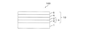
- FIG. 1 shows a schematic cross-sectional view of an example of the infrared reflective glass of the present disclosure.
- the infrared reflective glass 100 of FIG. 1 includes a glass plate 1 and an infrared reflective coating 10 provided on the glass plate 1.
- the infrared reflective film 10 is made of a multilayer film. Specifically, the infrared reflective coating 10 has a unit A composed of a first dielectric layer 2 and a metal layer 3 directly above the first dielectric layer 2. Further, the infrared reflective coating 10 has a second dielectric layer 5 on the uppermost layer and a third dielectric layer 4 directly below the second dielectric layer 5.
- the second dielectric layer 5 is formed from any one of the group consisting of titanium oxide, zinc oxide tin, zinc aluminum oxide, and silicon aluminum oxide.
- the third dielectric layer 4 is formed from any one of the group consisting of silicon nitride aluminum, silicon nitride aluminum, and silicon aluminum oxide.
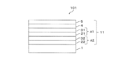
- FIG. 2 shows a schematic cross-sectional view of another example of the infrared reflective glass of the present disclosure.
- the infrared reflective glass 101 of FIG. 2 includes a glass plate 1 and an infrared reflective coating 11 provided on the glass plate 1.
- the infrared reflective film 11 is composed of a multilayer film, and has two units (a first dielectric layer 21 and the first dielectric layer) composed of a first dielectric layer and a metal layer immediately above the first dielectric layer. Except that the unit A1 composed of the metal layer 31 directly above the 21 and the unit A2) composed of the first dielectric layer 22 and the metal layer 32 directly above the first dielectric layer 22 are provided. It has the same configuration as the infrared reflective coating 10 shown in FIG.
- FIG. 3 shows a schematic cross-sectional view of another example of the infrared reflective glass of the present disclosure.
- the infrared reflective glass 102 of FIG. 3 includes a glass plate 1 and an infrared reflective coating 12 provided on the glass plate 1.
- the infrared reflective coating 12 is made of a multilayer film, and has three units (the first dielectric layer 21 and the first dielectric layer) composed of a first dielectric layer and a metal layer immediately above the first dielectric layer.
- the unit A1 composed of the metal layer 31 directly above the 21 and the first dielectric layer 22, the unit A2 composed of the metal layer 32 directly above the first dielectric layer 22, and the first dielectric layer 23. It has the same configuration as the infrared reflective coating 10 shown in FIG. 1 except that the unit A3) composed of the metal layer 33 directly above the first dielectric layer 23 is provided.
- the glass plate of the infrared reflective glass of the present disclosure is not particularly limited, and a glass plate known as a glass plate used for the infrared reflective glass can be used.
- the infrared reflective glass of the present disclosure can be used for various purposes, and one application example is an automobile window glass. Therefore, examples of the glass plate of the infrared reflective glass of the present disclosure include glass plates generally used for window glass for automobiles such as wind-cooled tempered glass, chemically strengthened glass, and laminated glass.
- the thickness of the glass plate is not particularly limited, but for example, when the infrared reflective glass of the present disclosure is used as a window glass for an automobile, the thickness range of the glass plate is preferably 0.3 mm to 5.0 mm. It is more preferably 0.0 mm to 4.0 mm, and even more preferably 1.5 to 3.5 mm.
- the infrared reflective glass of the present disclosure has an infrared reflective coating on one surface of a glass plate.
- the infrared reflective film is a multilayer film formed by laminating a large number of layers.
- the glass plate side is defined as "bottom” and the opposite side is defined as "top”.
- the multilayer film has at least one unit composed of a first dielectric layer and a metal layer immediately above the first dielectric layer.
- "directly above” means that it is directly above without intervening other layers. That is, in the unit, the first dielectric layer and the metal layer are directly laminated without interposing another layer, and the metal layer is provided on the first dielectric layer.
- the multilayer film has a second dielectric layer on the uppermost layer and a third dielectric layer directly below the second dielectric layer.
- the “top layer” is the uppermost layer in the multilayer film (that is, the layer farthest from the glass plate).
- directly below means that it is directly below without interposing another layer. That is, the second dielectric layer and the third dielectric layer are directly laminated without interposing another layer, and the third dielectric layer is provided under the second dielectric layer.
- the material constituting the first dielectric layer is not particularly limited, but the first dielectric layer preferably contains an oxide or a nitride.
- the first dielectric layer may be composed of one layer (single layer), or two or more layers may be laminated.
- the first dielectric layer may be composed of only a layer made of an oxide (a single layer made of an oxide or a layer made by laminating two or more layers made of an oxide). , It may be composed of only a layer made of a nitride (a single layer made of a nitride or a layer made by laminating two or more layers made of a nitride), or a layer made of an oxide. And a layer made of nitride may be laminated one layer or more respectively.
- the stacking order is not particularly limited.
- a preferable structure of the first dielectric layer is a structure in which only a layer made of an oxide is present, or a layer made of an oxide and a layer made of a nitride are each present in one layer and directly above the layer made of a nitride. It is a structure in which a layer made of oxide exists.
- the composition of the oxide is not particularly limited, but it is preferable that at least one of aluminum, titanium, zinc, and tin is contained as an element.
- the oxide is preferably titanium oxide, aluminum oxide, tin oxide, a laminate of titanium oxide and aluminum zinc oxide, or a laminate of aluminum zinc oxide and tin oxide, and is oxidized directly above titanium oxide. It is more preferable that the laminate is provided with zinc aluminum or the laminate provided with zinc aluminum oxide directly above the tin oxide.
- the composition of the nitride is not particularly limited, but it is preferable that at least one of silicon and aluminum is contained as an element.
- the nitride is preferably silicon nitride aluminum.
- the thickness of the first dielectric layer (when the first dielectric layer is formed by laminating a plurality of layers, the total thickness) is not particularly limited, but is preferably 5 nm to 100 nm, preferably 30 nm to 80 nm. More preferably.
- the metal constituting the metal layer is not particularly limited, but for example, silver, silver alloy (alloy with copper, palladium, platinum, etc.), niobium, nickel, chromium, nickel chromium, silicon aluminum, zinc, titanium, aluminum, zinc aluminum. And so on.
- silver or titanium is particularly preferable.
- the metal layer may be composed of only one layer (single layer), or may be a structure in which a plurality of metal layers are laminated.
- the order of lamination is not particularly limited.
- the metal layer is composed of a plurality of layers, for example, it is preferable that the metal layer is a metal layer in which a titanium layer is laminated on a silver layer.
- the thickness of the metal layer (when the metal layer is formed by laminating a plurality of layers, the total thickness) is not particularly limited, but is preferably 10 nm to 20 nm, and more preferably 15 nm to 20 nm.
- the silver layer is preferably 5 nm to 20 nm, and more preferably 10 nm to 16 nm.
- the multilayer film in the present disclosure includes at least one unit composed of a first dielectric layer and a metal layer, and the number of the units is not particularly limited, but the number of the units is one or more and five or less. It is preferable that the number is 2 or more and 4 or less.
- the second dielectric layer is formed from any one of the groups consisting of titanium oxide, tin zinc oxide, aluminum zinc oxide, and aluminum silicon oxide. From the viewpoint of adhesion to the third dielectric layer, the second dielectric layer is preferably formed from any one of the groups consisting of titanium oxide, zinc oxide tin and zinc aluminum oxide, and is made of zinc oxide aluminum. It is more preferably formed.
- the second dielectric layer may be composed of one layer (single layer), or two or more layers may be laminated.
- the thickness of the second dielectric layer (the total thickness when the second dielectric layer is composed of a plurality of layers) is not particularly limited, but is 10 nm from the viewpoint of scratch resistance and the appearance of the infrared reflective glass. The above is preferable, and it is more preferably 10 nm to 20 nm.
- the second dielectric layer is the uppermost layer of the multilayer film, but in addition to the uppermost layer, the second dielectric layer is composed of titanium oxide, zinc oxide, aluminum oxide, and oxidation. It may have one or more layers formed from any one of the group consisting of silicon-aluminum.
- the third dielectric layer is formed from any one of the group consisting of silicon nitride aluminum, silicon nitride aluminum, and silicon aluminum oxide. From the viewpoint of film hardness, the third dielectric layer is preferably formed of silicon nitride aluminum.
- the third dielectric layer may be composed of one layer (single layer), or two or more layers may be laminated.
- the thickness of the third dielectric layer (when the third dielectric layer is composed of a plurality of layers, the total thickness) is more than 10 nm from the viewpoint of film hardness and the appearance of the infrared reflective glass. It is preferably 20 nm to 50 nm.
- the third dielectric layer is provided directly below the second dielectric layer, which is the uppermost layer of the multilayer film. It may have one or more layers formed from any one of the group consisting of silicon nitride aluminum, silicon nitride aluminum oxynitride, and silicon aluminum oxide, which are layers having the same composition.
- the layer having the same composition as the third dielectric layer may be arranged at any position except the uppermost layer.
- the multilayer film in the present disclosure may have one or more other layers in addition to the above-mentioned layers.
- the other layer include a layer made of carbon.
- the overall film thickness of the infrared reflective film (multilayer film) in the present disclosure is not particularly limited, but is preferably 250 nm to 350 nm, more preferably 270 nm to 310 nm.
- the manufacturing method of the infrared reflective glass of the present disclosure is not particularly limited.
- the infrared reflective coating can be formed by, for example, a physical vapor deposition method (PVD) such as a sputtering method, a vapor deposition method, or an ion plating method, or a chemical vapor deposition method (CVD) such as plasma CVD.
- PVD physical vapor deposition method
- CVD chemical vapor deposition method
- it can form a uniform film on a large-area substrate, is suitable for mass production, can easily control the film composition, can produce a highly reproducible film, and has high adhesion to the substrate.
- the sputtering method is preferable because a film can be produced.
- the infrared reflective glass of the present disclosure does not require a natural oxidation step as is performed in the technique described in Patent Document 2, and can be manufactured by a relatively easy manufacturing process.
- silicon aluminum is SiAl
- aluminum oxide is Al 2 O 3
- silicon aluminum oxide is SiAlO
- silicon nitride aluminum is SiAlN
- silicon oxynitride is SiAlON
- zinc aluminum is ZnAl
- zinc tin is zinc.
- silver is Ag
- titanium is Ti
- titanium oxide is TiO 2
- zinc aluminum oxide is ZnAlO
- tin oxide is ZnSnO.
- Example 1 On the glass plate which is a transparent base material, SiAlN layer (10 nm), TiO 2 layer (8 nm), ZnAlO layer (16 nm), Ag layer (13 nm), Ti layer (3 nm), ZnSnO layer (in order from the glass plate side). 63 nm), ZnAlO layer (16 nm), Ag layer (15 nm), Ti layer (3 nm), ZnSnO layer (60 nm), ZnAlO layer (16 nm), Ag layer (12 nm), Ti layer (3 nm), third dielectric layer.
- a SiAlN layer (24 nm) was formed as a second dielectric layer, and a ZnSnO layer (13 nm) was formed as a second dielectric layer (the film thickness of each layer is described in parentheses).
- all the layers constituting the infrared reflective coating of Example 1 are placed on the cathode in the vacuum chamber of the film forming apparatus with the SiAl target, TiO 2 target, ZnAl target, ZnSn target, Ag target, and Ti target as sputtering targets.
- the vacuum layer is exhausted to 5.0 ⁇ 10 -4 Pa or less, and then a discharge gas such as argon, oxygen, or nitrogen is used as a sputtering gas so that the pressure in the vacuum chamber becomes an arbitrary pressure.
- the infrared reflective glass thus obtained was subjected to a tabor test.
- the tabor test was carried out according to the following procedure, the surface of the infrared reflective film after the test was observed with a microscope, and the scratch resistance of the infrared reflective film was evaluated on a two-point scale of good ( ⁇ ) or poor (x).
- the tabor test was carried out by a tabor wear tester (TS-2, manufactured by Toyo Seiki Seisakusho Co., Ltd.), which imitated roller transfer.
- the testing machine is equipped with two wear wheels (manufactured by Daitron Co., Ltd., CS-10F) wrapped with Al 2 O 3 sleeves (manufactured by Nichibi Co., Ltd., SV-60-G2 / 2-5).
- a 10 cm square glass with an infrared reflective coating was fixed on top.
- the test was carried out at a rotation speed of 72 rpm for 50 rotations.
- Examples 2 to 7, Comparative Examples 1 to 12 The combinations of materials and layer thicknesses of the second dielectric layer and the third dielectric layer are as shown in Tables 1 and 2, and other than that, infrared reflective glass has the same film structure and manufacturing process as in Example 1. Was prepared, and the same evaluation method as in Example 1 was carried out.
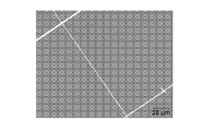
- FIG. 4 shows a micrograph of the appearance of Example 1 after the tabor test
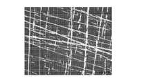
- FIG. 5 shows a micrograph of the appearance of Comparative Example 1 after the tabor test.
- the infrared reflective glass of the present disclosure can be manufactured by a relatively simple manufacturing process and has excellent scratch resistance.
Landscapes
- Physics & Mathematics (AREA)
- Chemical & Material Sciences (AREA)
- Optics & Photonics (AREA)
- General Physics & Mathematics (AREA)
- Chemical Kinetics & Catalysis (AREA)
- Geochemistry & Mineralogy (AREA)
- Materials Engineering (AREA)
- Organic Chemistry (AREA)
- General Chemical & Material Sciences (AREA)
- Life Sciences & Earth Sciences (AREA)
- Engineering & Computer Science (AREA)
- Surface Treatment Of Glass (AREA)
- Optical Filters (AREA)
Abstract
本開示の赤外線反射ガラスは、ガラス板と、前記ガラス板上に設けられた赤外線反射被膜と、を備え、前記赤外線反射被膜は多層膜からなり、前記多層膜において、前記ガラス板側を下とし、その反対側を上と定義した場合、前記多層膜は、第一誘電体層と、前記第一誘電体層の直上の金属層とからなるユニットを少なくとも1つ有し、前記多層膜は、最上層に第二誘電体層を有し、前記第二誘電体層の直下に第三誘電体層を有し、前記第二誘電体層は、酸化チタン、酸化亜鉛スズ、酸化亜鉛アルミニウム、及び酸化ケイ素アルミニウムからなる群のうちいずれか一つから形成され、前記第三誘電体層は、窒化ケイ素アルミニウム、酸窒化ケイ素アルミニウム、及び酸化ケイ素アルミニウムからなる群のうちいずれか一つから形成され、前記第三誘電体層の厚さは10nmを超えるものである。
Description
本開示は、赤外線反射ガラスに関する。
近年の建築物の室内や自動車内の冷暖房コスト削減や快適性向上の要求に伴い、銀等の金属層を用いた赤外線反射ガラスの需要が増えている。赤外線反射ガラスは、透明基材の上に誘電体層、金属層を積層した構成がよく用いられる。金属は自由電子をもつという特徴から、光に対する高い反射率を有し、特に銀は可視光線や赤外線の波長を強く反射する為、上記の金属層としてよく用いられている。誘電体層は、赤外線反射ガラス全体の色調調整や、金属層を安定して積層するための下地として使用される。このように、赤外線反射ガラスは、複数の機能層をガラス板表面上に積層させることにより、入射する赤外線の大部分を反射し、高い断熱性を有する。
赤外線反射ガラスは、運搬時や取扱時において、搬送レールやコンベア等の運搬装置、モールドやロボットのアーム等の保持部材、又は人の手との接触により積層部分が損傷し、低放射膜の性能が落ちることがしばしばある。これを考慮して、赤外線反射ガラスの最上層にバリア層を施し、積層部分を保護する方法が採用されることが多い。
特許文献1では、高硬度を有するケイ素及び/又はアルミニウムの窒化物又は酸窒化物をバリア層として積層させ、赤外線反射ガラスの積層構造を保護している。
特許文献2では、金属、金属合金、金属化合物、又は金属間化合物をバリア層として5nm以下の厚さで赤外線反射ガラスの最上層に積層させ、バリア層を空気中で酸化させ圧縮応力を付与することで赤外線反射ガラスに耐傷性を付与している。
特許文献1では、高硬度を有するケイ素及び/又はアルミニウムの窒化物又は酸窒化物をバリア層として積層させ、赤外線反射ガラスの積層構造を保護している。
特許文献2では、金属、金属合金、金属化合物、又は金属間化合物をバリア層として5nm以下の厚さで赤外線反射ガラスの最上層に積層させ、バリア層を空気中で酸化させ圧縮応力を付与することで赤外線反射ガラスに耐傷性を付与している。
しかしながら、本発明者らが、特許文献1に開示されているように、最上層をケイ素及び/又はアルミニウムの窒化物又は酸窒化物とした赤外線反射ガラスを作製し、赤外線反射ガラスの耐傷性を評価するテーバー試験を実施した結果、赤外線反射被膜の積層部分の損傷を抑制することはできるものの、最上層自体に微細な傷が形成してしまい、赤外線反射ガラス全体の良好な外観維持が困難になることが分かった。
また、特許文献2に開示される赤外線反射ガラスの製造方法は、従来のスパッタリング法による成膜工程に加えて長時間のトップコート層の酸化工程を必要とするため、赤外線反射ガラスの生産タクトが低下する可能性がある。
また、特許文献2に開示される赤外線反射ガラスの製造方法は、従来のスパッタリング法による成膜工程に加えて長時間のトップコート層の酸化工程を必要とするため、赤外線反射ガラスの生産タクトが低下する可能性がある。
以上から、本開示は、耐傷性に優れ、かつ比較的容易な製造工程で製造できる赤外線反射ガラスを提供することを課題とする。
本開示の課題は、下記構成により解決される。
[1]
ガラス板と、前記ガラス板上に設けられた赤外線反射被膜と、を備える赤外線反射ガラスであって、
前記赤外線反射被膜は多層膜からなり、
前記多層膜において、前記ガラス板側を下とし、その反対側を上と定義した場合、
前記多層膜は、第一誘電体層と、前記第一誘電体層の直上の金属層とからなるユニットを少なくとも1つ有し、
前記多層膜は、最上層に第二誘電体層を有し、前記第二誘電体層の直下に第三誘電体層を有し、
前記第二誘電体層は、酸化チタン、酸化亜鉛スズ、酸化亜鉛アルミニウム、及び酸化ケイ素アルミニウムからなる群のうちいずれか一つから形成され、
前記第三誘電体層は、窒化ケイ素アルミニウム、酸窒化ケイ素アルミニウム、及び酸化ケイ素アルミニウムからなる群のうちいずれか一つから形成され、
前記第三誘電体層の厚さは10nmを超えるものである、赤外線反射ガラス。
[2]
前記第二誘電体層は酸化チタン、酸化亜鉛スズ、及び酸化亜鉛アルミニウムからなる群のうちいずれか一つから形成される、[1]に記載の赤外線反射ガラス。
[3]
前記第二誘電体層は酸化亜鉛アルミニウムから形成される、[1]に記載の赤外線反射ガラス。
[4]
前記第三誘電体層は、窒化ケイ素アルミニウムから形成される、[1]から[3]のいずれか1項に記載の赤外線反射ガラス。
[5]
前記第二誘電体層の厚さは、10nm以上である、[1]から[5]のいずれか1項に記載の赤外線反射ガラス。
[6]
前記第三誘電体層の厚さは、20nm~50nmである、[1]から[5]のいずれか1項に記載の赤外線反射ガラス。
[1]
ガラス板と、前記ガラス板上に設けられた赤外線反射被膜と、を備える赤外線反射ガラスであって、
前記赤外線反射被膜は多層膜からなり、
前記多層膜において、前記ガラス板側を下とし、その反対側を上と定義した場合、
前記多層膜は、第一誘電体層と、前記第一誘電体層の直上の金属層とからなるユニットを少なくとも1つ有し、
前記多層膜は、最上層に第二誘電体層を有し、前記第二誘電体層の直下に第三誘電体層を有し、
前記第二誘電体層は、酸化チタン、酸化亜鉛スズ、酸化亜鉛アルミニウム、及び酸化ケイ素アルミニウムからなる群のうちいずれか一つから形成され、
前記第三誘電体層は、窒化ケイ素アルミニウム、酸窒化ケイ素アルミニウム、及び酸化ケイ素アルミニウムからなる群のうちいずれか一つから形成され、
前記第三誘電体層の厚さは10nmを超えるものである、赤外線反射ガラス。
[2]
前記第二誘電体層は酸化チタン、酸化亜鉛スズ、及び酸化亜鉛アルミニウムからなる群のうちいずれか一つから形成される、[1]に記載の赤外線反射ガラス。
[3]
前記第二誘電体層は酸化亜鉛アルミニウムから形成される、[1]に記載の赤外線反射ガラス。
[4]
前記第三誘電体層は、窒化ケイ素アルミニウムから形成される、[1]から[3]のいずれか1項に記載の赤外線反射ガラス。
[5]
前記第二誘電体層の厚さは、10nm以上である、[1]から[5]のいずれか1項に記載の赤外線反射ガラス。
[6]
前記第三誘電体層の厚さは、20nm~50nmである、[1]から[5]のいずれか1項に記載の赤外線反射ガラス。
本開示によれば、耐傷性に優れ、かつ比較的容易な製造工程で製造できる赤外線反射ガラスを提供することができる。
本開示の赤外線反射ガラスは、ガラス板と、前記ガラス板上に設けられた赤外線反射被膜と、を備える赤外線反射ガラスであって、前記赤外線反射被膜は多層膜からなり、前記多層膜において、前記ガラス板側を下とし、その反対側を上と定義した場合、前記多層膜は、第一誘電体層と、前記第一誘電体層の直上の金属層とからなるユニットを少なくとも1つ有し、前記多層膜は、最上層に第二誘電体層を有し、前記第二誘電体層の直下に第三誘電体層を有し、前記第二誘電体層は、酸化チタン、酸化亜鉛スズ、酸化亜鉛アルミニウム、及び酸化ケイ素アルミニウムからなる群のうちいずれか一つから形成され、前記第三誘電体層は、窒化ケイ素アルミニウム、酸窒化ケイ素アルミニウム、及び酸化ケイ素アルミニウムからなる群のうちいずれか一つから形成され、前記第三誘電体層の厚さは10nmを超えるものである、赤外線反射ガラスである。
図1に、本開示の赤外線反射ガラスの一例の断面模式図を示す。
図1の赤外線反射ガラス100は、ガラス板1と、ガラス板1上に設けられた赤外線反射被膜10とを備える。
赤外線反射被膜10は多層膜からなる。具体的には、赤外線反射被膜10は、第一誘電体層2と、第一誘電体層2の直上の金属層3とからなるユニットAを有する。さらに赤外線反射被膜10は、最上層に第二誘電体層5を有し、第二誘電体層5の直下に第三誘電体層4を有する。
第二誘電体層5は、酸化チタン、酸化亜鉛スズ、酸化亜鉛アルミニウム、及び酸化ケイ素アルミニウムからなる群のうちいずれか一つから形成される。
第三誘電体層4は、窒化ケイ素アルミニウム、酸窒化ケイ素アルミニウム、及び酸化ケイ素アルミニウムからなる群のうちいずれか一つから形成される。
図1の赤外線反射ガラス100は、ガラス板1と、ガラス板1上に設けられた赤外線反射被膜10とを備える。
赤外線反射被膜10は多層膜からなる。具体的には、赤外線反射被膜10は、第一誘電体層2と、第一誘電体層2の直上の金属層3とからなるユニットAを有する。さらに赤外線反射被膜10は、最上層に第二誘電体層5を有し、第二誘電体層5の直下に第三誘電体層4を有する。
第二誘電体層5は、酸化チタン、酸化亜鉛スズ、酸化亜鉛アルミニウム、及び酸化ケイ素アルミニウムからなる群のうちいずれか一つから形成される。
第三誘電体層4は、窒化ケイ素アルミニウム、酸窒化ケイ素アルミニウム、及び酸化ケイ素アルミニウムからなる群のうちいずれか一つから形成される。
図2に、本開示の赤外線反射ガラスの別の一例の断面模式図を示す。
図2の赤外線反射ガラス101は、ガラス板1と、ガラス板1上に設けられた赤外線反射被膜11とを備える。
赤外線反射被膜11は多層膜からなり、第一誘電体層と、前記第一誘電体層の直上の金属層とからなるユニットが2つ(第一誘電体層21と、前記第一誘電体層21の直上の金属層31とからなるユニットA1、及び、第一誘電体層22と、前記第一誘電体層22の直上の金属層32とからなるユニットA2)設けられていること以外は、図1に示した赤外線反射被膜10と同様の構成を有する。
図2の赤外線反射ガラス101は、ガラス板1と、ガラス板1上に設けられた赤外線反射被膜11とを備える。
赤外線反射被膜11は多層膜からなり、第一誘電体層と、前記第一誘電体層の直上の金属層とからなるユニットが2つ(第一誘電体層21と、前記第一誘電体層21の直上の金属層31とからなるユニットA1、及び、第一誘電体層22と、前記第一誘電体層22の直上の金属層32とからなるユニットA2)設けられていること以外は、図1に示した赤外線反射被膜10と同様の構成を有する。
図3に、本開示の赤外線反射ガラスの別の一例の断面模式図を示す。
図3の赤外線反射ガラス102は、ガラス板1と、ガラス板1上に設けられた赤外線反射被膜12とを備える。
赤外線反射被膜12は多層膜からなり、第一誘電体層と、前記第一誘電体層の直上の金属層とからなるユニットが3つ(第一誘電体層21と、前記第一誘電体層21の直上の金属層31とからなるユニットA1、第一誘電体層22と、前記第一誘電体層22の直上の金属層32とからなるユニットA2、及び、第一誘電体層23と、前記第一誘電体層23の直上の金属層33とからなるユニットA3)設けられていること以外は、図1に示した赤外線反射被膜10と同様の構成を有する。
図3の赤外線反射ガラス102は、ガラス板1と、ガラス板1上に設けられた赤外線反射被膜12とを備える。
赤外線反射被膜12は多層膜からなり、第一誘電体層と、前記第一誘電体層の直上の金属層とからなるユニットが3つ(第一誘電体層21と、前記第一誘電体層21の直上の金属層31とからなるユニットA1、第一誘電体層22と、前記第一誘電体層22の直上の金属層32とからなるユニットA2、及び、第一誘電体層23と、前記第一誘電体層23の直上の金属層33とからなるユニットA3)設けられていること以外は、図1に示した赤外線反射被膜10と同様の構成を有する。
[ガラス板]
本開示の赤外線反射ガラスのガラス板としては、特に限定されず、赤外線反射ガラスに用いられるガラス板として公知のガラス板を用いることができる。本開示の赤外線反射ガラスは種々の用途に用いることができるが、1つの適用例として自動車用窓ガラスが挙げられる。したがって、本開示の赤外線反射ガラスのガラス板としては、例えば、風冷強化ガラス、化学強化ガラス、合わせガラス等の自動車用窓ガラスに一般に用いられるガラス板も挙げられる。
本開示の赤外線反射ガラスのガラス板としては、特に限定されず、赤外線反射ガラスに用いられるガラス板として公知のガラス板を用いることができる。本開示の赤外線反射ガラスは種々の用途に用いることができるが、1つの適用例として自動車用窓ガラスが挙げられる。したがって、本開示の赤外線反射ガラスのガラス板としては、例えば、風冷強化ガラス、化学強化ガラス、合わせガラス等の自動車用窓ガラスに一般に用いられるガラス板も挙げられる。
ガラス板の厚さは特に限定されないが、例えば、本開示の赤外線反射ガラスを自動車用窓ガラスとして用いる場合には、ガラス板の厚さの範囲として、0.3mm~5.0mmが好ましく、1.0mm~4.0mmがより好ましく、1.5~3.5mmが更に好ましい。
[赤外線反射被膜]
本開示の赤外線反射ガラスは、ガラス板の一方の面上に赤外線反射被膜を有する。
赤外線反射被膜は、多数の層を積層してなる多層膜である。多層膜において、ガラス板側を「下」とし、その反対側を「上」と定義する。
多層膜は、第一誘電体層と、第一誘電体層の直上の金属層とからなるユニットを少なくとも1つ有する。ここで、「直上」とは、他の層を介さずに直接上にあることを表す。すなわち、前記ユニットにおいて、第一誘電体層と金属層とは他の層を介さずに直接積層されており、かつ第一誘電体層の上に金属層が設けられている。
また、多層膜は、最上層に第二誘電体層を有し、第二誘電体層の直下に第三誘電体層を有する。ここで、「最上層」とは多層膜において最も上にある層(すなわち、ガラス板から最も遠い層)である。また、「直下」とは、他の層を介さずに直接下にあることを表す。すなわち、第二誘電体層と第三誘電体層とは他の層を介さずに直接積層されており、かつ第二誘電体層の下に第三誘電体層が設けられている。
本開示の赤外線反射ガラスは、ガラス板の一方の面上に赤外線反射被膜を有する。
赤外線反射被膜は、多数の層を積層してなる多層膜である。多層膜において、ガラス板側を「下」とし、その反対側を「上」と定義する。
多層膜は、第一誘電体層と、第一誘電体層の直上の金属層とからなるユニットを少なくとも1つ有する。ここで、「直上」とは、他の層を介さずに直接上にあることを表す。すなわち、前記ユニットにおいて、第一誘電体層と金属層とは他の層を介さずに直接積層されており、かつ第一誘電体層の上に金属層が設けられている。
また、多層膜は、最上層に第二誘電体層を有し、第二誘電体層の直下に第三誘電体層を有する。ここで、「最上層」とは多層膜において最も上にある層(すなわち、ガラス板から最も遠い層)である。また、「直下」とは、他の層を介さずに直接下にあることを表す。すなわち、第二誘電体層と第三誘電体層とは他の層を介さずに直接積層されており、かつ第二誘電体層の下に第三誘電体層が設けられている。
(第一誘電体層)
第一誘電体層を構成する材料は特に限定されないが、第一誘電体層は、酸化物又は窒化物を含むことが好ましい。
第一誘電体層を構成する材料は特に限定されないが、第一誘電体層は、酸化物又は窒化物を含むことが好ましい。
第一誘電体層は、1つの層(単層)からなっていてもよいし、2つ以上の層が積層されていてもよい。
第一誘電体層は、酸化物からなる層のみ(酸化物からなる単層でもよいし、酸化物からなる層を2つ以上積層してなる層でもよい。)で構成されていてもよいし、窒化物からなる層のみ(窒化物からなる単層でもよいし、窒化物からなる層を2つ以上積層してなる層でもよい。)で構成されていてもよいし、酸化物からなる層及び窒化物からなる層がそれぞれ一層以上積層して構成されていてもよい。また、第一誘電体層が数種類の層で構成される場合、その積層順は特に限定されない。
好ましい第一誘電体層の構成は、酸化物からなる層のみが一層存在する構成、又は酸化物からなる層と窒化物からなる層がそれぞれ一層ずつ存在し、かつ窒化物からなる層の直上に酸化物からなる層が存在する構成である。
好ましい第一誘電体層の構成は、酸化物からなる層のみが一層存在する構成、又は酸化物からなる層と窒化物からなる層がそれぞれ一層ずつ存在し、かつ窒化物からなる層の直上に酸化物からなる層が存在する構成である。
第一誘電体層が酸化物を含む場合、当該酸化物の組成は特に限定されないが、アルミニウム、チタン、亜鉛、及びスズの少なくとも1種を元素として含むことが好ましい。当該酸化物としては、酸化チタン、酸化亜鉛アルミニウム、酸化亜鉛スズ、酸化チタンと酸化亜鉛アルミニウムの積層体、又は酸化亜鉛アルミニウムと酸化亜鉛スズの積層体であることが好ましく、酸化チタンの直上に酸化亜鉛アルミニウムを備える積層体、又は酸化亜鉛スズの直上に酸化亜鉛アルミニウムを備える積層体であることがより好ましい。
第一誘電体層が窒化物を含む場合、当該窒化物の組成は特に限定されないが、シリコン及びアルミニウムの少なくとも1種を元素として含むことが好ましい。当該窒化物は窒化ケイ素アルミニウムであることが好ましい。
第一誘電体層の厚さ(第一誘電体層が複数の層を積層してなる場合は、全体の厚さ)は特に限定されないが、5nm~100nmであることが好ましく、30nm~80nmであることがより好ましい。
(金属層)
金属層を構成する金属は特に限定されないが、例えば、銀、銀合金(銅、パラジウム、白金等との合金)、ニオブ、ニッケル、クロム、ニッケルクロム、ケイ素アルミニウム、亜鉛、チタン、アルミニウム、亜鉛アルミニウム等が挙げられる。金属層を構成する金属としては、特に銀又はチタンが好ましい。
金属層を構成する金属は特に限定されないが、例えば、銀、銀合金(銅、パラジウム、白金等との合金)、ニオブ、ニッケル、クロム、ニッケルクロム、ケイ素アルミニウム、亜鉛、チタン、アルミニウム、亜鉛アルミニウム等が挙げられる。金属層を構成する金属としては、特に銀又はチタンが好ましい。
金属層は、1つの層(単層)のみで構成されていてもよいし、複数の金属層が積層した構成であってもよい。金属層が複数の層からなる場合、積層の順番は特に限定されない。金属層が複数の層からなる場合としては、例えば、銀層の上にチタン層が積層した金属層であることが好ましい。
金属層の厚さ(金属層が複数の層を積層してなる場合は、全体の厚さ)は特に限定されないが、10nm~20nmであることが好ましく、15nm~20nmであることがより好ましい。特に金属層に銀層が含まれている場合、銀層は5nm~20nmであることが好ましく、10nm~16nmであることがより好ましい。
本開示における多層膜は、第一誘電体層と金属層とからなるユニットを少なくとも1つ含むものであり、当該ユニットの数に特に限定はないが、当該ユニットの数は1つ以上5つ以下であることが好ましく、2つ以上4つ以下であることがより好ましい。
(第二誘電体層)
第二誘電体層は、酸化チタン、酸化亜鉛スズ、酸化亜鉛アルミニウム、及び酸化ケイ素アルミニウムからなる群のうちいずれか一つから形成される。第三誘電体層との密着性の観点から、第二誘電体層は、酸化チタン、酸化亜鉛スズ及び酸化亜鉛アルミニウムからなる群のうちいずれかひとつから形成されることが好ましく、酸化亜鉛アルミニウムから形成されることがより好ましい。
第二誘電体層は、酸化チタン、酸化亜鉛スズ、酸化亜鉛アルミニウム、及び酸化ケイ素アルミニウムからなる群のうちいずれか一つから形成される。第三誘電体層との密着性の観点から、第二誘電体層は、酸化チタン、酸化亜鉛スズ及び酸化亜鉛アルミニウムからなる群のうちいずれかひとつから形成されることが好ましく、酸化亜鉛アルミニウムから形成されることがより好ましい。
第二誘電体層は、1つの層(単層)からなっていてもよいし、2つ以上の層が積層されていてもよい。
第二誘電体層の厚さ(第二誘電体層が複数の層を積層してなる場合は、全体の厚さ)は特に限定されないが、耐傷性及び赤外線反射ガラスの外観の観点から、10nm以上であることが好ましく、10nm~20nmであることがより好ましい。
本開示において、第二誘電体層は多層膜の最上層であるが、最上層に加えて、その他の層として前記第二誘電体層は、酸化チタン、酸化亜鉛スズ、酸化亜鉛アルミニウム、及び酸化ケイ素アルミニウムからなる群のうちいずれか一つから形成される層を1層以上有していても良い。
(第三誘電体層)
第三誘電体層は、窒化ケイ素アルミニウム、酸窒化ケイ素アルミニウム、及び酸化ケイ素アルミニウムからなる群のうちいずれか一つから形成される。膜硬度の観点から、第三誘電体層は、窒化ケイ素アルミニウムから形成されることが好ましい。
第三誘電体層は、窒化ケイ素アルミニウム、酸窒化ケイ素アルミニウム、及び酸化ケイ素アルミニウムからなる群のうちいずれか一つから形成される。膜硬度の観点から、第三誘電体層は、窒化ケイ素アルミニウムから形成されることが好ましい。
第三誘電体層は、1つの層(単層)からなっていてもよいし、2つ以上の層が積層されていてもよい。
第三誘電体層の厚さ(第三誘電体層が複数の層を積層してなる場合は、全体の厚さ)は、膜硬度及び赤外線反射ガラスの外観の観点から、10nmを超えるものであり、20nm~50nmであることが好ましい。
本開示において、第三誘電体層は多層膜の最上層である第二誘電体層の直下に設けられるが、最上層の直下の層に加えて、その他の層として、第三誘電体層と同様の組成の層である、窒化ケイ素アルミニウム、酸窒化ケイ素アルミニウム、及び酸化ケイ素アルミニウムからなる群のうちいずれか一つから形成される層を1層以上有していても良い。なお、本開示における多層膜中、上記第三誘電体層と同様の組成の層は、最上層を除き、いずれの位置に配置されてもよい。
(その他の層)
本開示における多層膜は上記した各層に加えて、その他の層を1層以上有していても良い。その他の層としては、例えばカーボンからなる層が挙げられる。
本開示における多層膜は上記した各層に加えて、その他の層を1層以上有していても良い。その他の層としては、例えばカーボンからなる層が挙げられる。
本開示における赤外線反射被膜(多層膜)の全体の膜厚としては、特に限定されないが、250nm~350nmが好ましく、270nm~310nmがより好ましい。
本開示の赤外線反射ガラスの製造方法は特に限定されない。赤外線反射被膜は、例えば、スパッタリング法、蒸着法、イオンプレーティング法等の物理気相成長法(PVD)や、プラズマCVD等の化学気相成長法(CVD)で形成可能である。特に、大面積の基材に対して均一に成膜可能であり、量産に適していること、膜組成を制御しやすく、再現性が高い膜を作製できること、基材に対し高い密着性を有する膜を作製できること、などの理由から、スパッタリング法が好ましい。
本開示の赤外線反射ガラスは、特許文献2に記載された技術において行われているような自然酸化工程が不要であり、比較的容易な製造工程で製造することができる。
以下、本開示の実施例について説明するが、本開示は以下の実施例に限定されない。また、以下の実施例及び比較例において、ケイ素アルミニウムをSiAl、酸化アルミニウムをAl2O3、酸化ケイ素アルミニウムをSiAlO、窒化ケイ素アルミニウムをSiAlN、酸窒化ケイ素アルミニウムをSiAlON、亜鉛アルミニウムをZnAl、亜鉛スズをZnSn、銀をAg、チタンをTi、酸化チタンをTiO2、酸化亜鉛アルミニウムをZnAlO、及び酸化亜鉛スズをZnSnOと表記する。
[実施例1]
透明基材であるガラス板上に、ガラス板側から順に、SiAlN層(10nm)、TiO2層(8nm)、ZnAlO層(16nm)、Ag層(13nm)、Ti層(3nm)、ZnSnO層(63nm)、ZnAlO層(16nm)、Ag層(15nm)、Ti層(3nm)、ZnSnO層(60nm)、ZnAlO層(16nm)、Ag層(12nm)、Ti層(3nm)、第三誘電体層としてSiAlN層(24nm)、第二誘電体層としてZnSnO層(13nm)を成膜した(括弧内には各層の膜厚を記載した)。ここで、実施例1の赤外線反射被膜を構成する全ての層は、成膜装置の真空槽内にSiAlターゲット、TiO2ターゲット、ZnAlターゲット、ZnSnターゲット、Agターゲット、Tiターゲットをスパッタターゲットとしてカソード上に設置し、真空層を5.0×10⁻⁴Pa以下となるまで排気し、ついで、スパッタガスとして、アルゴン、酸素、窒素などの放電ガスを真空槽内の圧力が任意の圧力になるように可変バルブの開度を調整しながら導入し、続いて、DCパルス電源を用いて設置したターゲットに電圧を印加してスパッタリングを行い、ターゲットの下を通るようにガラス板を搬送することにより成膜した。
このようにして得られた赤外線反射ガラスについて、テーバー試験を実施した。テーバー試験は以下の手順に従って実施し、試験後の赤外線反射被膜の表面を顕微鏡で観察し、赤外線反射被膜の耐傷性を、良好(〇)又は不良(×)の2段階で評価した。
透明基材であるガラス板上に、ガラス板側から順に、SiAlN層(10nm)、TiO2層(8nm)、ZnAlO層(16nm)、Ag層(13nm)、Ti層(3nm)、ZnSnO層(63nm)、ZnAlO層(16nm)、Ag層(15nm)、Ti層(3nm)、ZnSnO層(60nm)、ZnAlO層(16nm)、Ag層(12nm)、Ti層(3nm)、第三誘電体層としてSiAlN層(24nm)、第二誘電体層としてZnSnO層(13nm)を成膜した(括弧内には各層の膜厚を記載した)。ここで、実施例1の赤外線反射被膜を構成する全ての層は、成膜装置の真空槽内にSiAlターゲット、TiO2ターゲット、ZnAlターゲット、ZnSnターゲット、Agターゲット、Tiターゲットをスパッタターゲットとしてカソード上に設置し、真空層を5.0×10⁻⁴Pa以下となるまで排気し、ついで、スパッタガスとして、アルゴン、酸素、窒素などの放電ガスを真空槽内の圧力が任意の圧力になるように可変バルブの開度を調整しながら導入し、続いて、DCパルス電源を用いて設置したターゲットに電圧を印加してスパッタリングを行い、ターゲットの下を通るようにガラス板を搬送することにより成膜した。
このようにして得られた赤外線反射ガラスについて、テーバー試験を実施した。テーバー試験は以下の手順に従って実施し、試験後の赤外線反射被膜の表面を顕微鏡で観察し、赤外線反射被膜の耐傷性を、良好(〇)又は不良(×)の2段階で評価した。
[テーバー試験手順]
テーバー試験は、ローラー搬送を模した摩耗試験をテーバー摩耗試験機(株式会社東洋精機製作所製、TS-2)にて実施した。試験機にはAl2O3スリーブ(株式会社ニチビ製、SV-60-G2/2-5)を巻いた2個の摩耗輪(ダイトロン株式会社製、CS-10F)を設置し、試験機台上には10cm角の赤外線反射被膜付きガラスを固定した。試験は回転速度72rpmにて50回転実施した。
テーバー試験は、ローラー搬送を模した摩耗試験をテーバー摩耗試験機(株式会社東洋精機製作所製、TS-2)にて実施した。試験機にはAl2O3スリーブ(株式会社ニチビ製、SV-60-G2/2-5)を巻いた2個の摩耗輪(ダイトロン株式会社製、CS-10F)を設置し、試験機台上には10cm角の赤外線反射被膜付きガラスを固定した。試験は回転速度72rpmにて50回転実施した。
[テーバー評価方法]
テーバー試験実施後のサンプルの外観評価は光学顕微鏡(オリンパス株式会社製、MX61L)の明視野観察(100倍)にて実施した。
テーバー試験実施後のサンプルの外観評価は光学顕微鏡(オリンパス株式会社製、MX61L)の明視野観察(100倍)にて実施した。
[実施例2~7、比較例1~12]
第二誘電体層と第三誘電体層における、材質や層厚の組み合わせを、表1~表2に示したものとし、それ以外は実施例1と同様の膜構成及び製造工程として赤外線反射ガラスを作製し、実施例1と同様の評価方法を実施した。
第二誘電体層と第三誘電体層における、材質や層厚の組み合わせを、表1~表2に示したものとし、それ以外は実施例1と同様の膜構成及び製造工程として赤外線反射ガラスを作製し、実施例1と同様の評価方法を実施した。
実施例、比較例のガラス構成を下記表1、表2にそれぞれ示す。

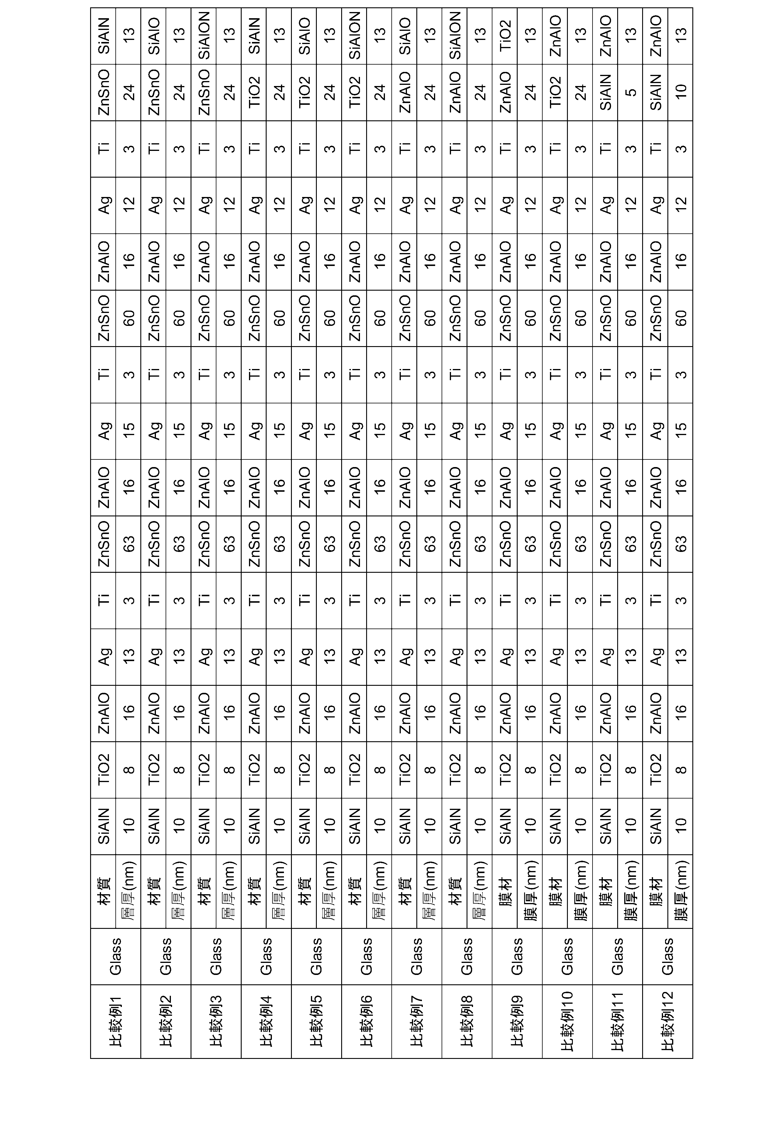
実施例、比較例のテーバー試験後の外観評価の結果を下記表3に示す。また、実施例1のテーバー試験後の外観の顕微鏡写真を図4、比較例1のテーバー試験後の外観の顕微鏡写真を図5に示す。

実施例では、外観評価は全て良好であり、良好な耐傷性を有していることを示している。一方比較例では、外観評価は全て不良であった。
以上より、本開示の赤外線反射ガラスは、比較的容易な製造工程で作製でき、耐傷性に優れることが分かる。
1: ガラス板
2、21、22、23: 第一誘電体層
3、31、32、33: 金属層
4: 第三誘電体層
5: 第二誘電体層
10、11、12: 赤外線反射被膜
100、101、102: 赤外線反射ガラス
A、A1、A2、A3: ユニット
2、21、22、23: 第一誘電体層
3、31、32、33: 金属層
4: 第三誘電体層
5: 第二誘電体層
10、11、12: 赤外線反射被膜
100、101、102: 赤外線反射ガラス
A、A1、A2、A3: ユニット
Claims (6)
- ガラス板と、前記ガラス板上に設けられた赤外線反射被膜と、を備える赤外線反射ガラスであって、
前記赤外線反射被膜は多層膜からなり、
前記多層膜において、前記ガラス板側を下とし、その反対側を上と定義した場合、
前記多層膜は、第一誘電体層と、前記第一誘電体層の直上の金属層とからなるユニットを少なくとも1つ有し、
前記多層膜は、最上層に第二誘電体層を有し、前記第二誘電体層の直下に第三誘電体層を有し、
前記第二誘電体層は、酸化チタン、酸化亜鉛スズ、酸化亜鉛アルミニウム、及び酸化ケイ素アルミニウムからなる群のうちいずれか一つから形成され、
前記第三誘電体層は、窒化ケイ素アルミニウム、酸窒化ケイ素アルミニウム、及び酸化ケイ素アルミニウムからなる群のうちいずれか一つから形成され、
前記第三誘電体層の厚さは10nmを超えるものである、
赤外線反射ガラス。 - 前記第二誘電体層は酸化チタン、酸化亜鉛スズ、及び酸化亜鉛アルミニウムからなる群のうちいずれか一つから形成される、請求項1に記載の赤外線反射ガラス。
- 前記第二誘電体層は酸化亜鉛アルミニウムから形成される、請求項1に記載の赤外線反射ガラス。
- 前記第三誘電体層は、窒化ケイ素アルミニウムから形成される、請求項1から3のいずれか1項に記載の赤外線反射ガラス。
- 前記第二誘電体層の厚さは、10nm以上である、請求項1から4のいずれか1項に記載の赤外線反射ガラス。
- 前記第三誘電体層の厚さは、20nm~50nmである、請求項1から5のいずれか1項に記載の赤外線反射ガラス。
Applications Claiming Priority (2)
| Application Number | Priority Date | Filing Date | Title |
|---|---|---|---|
| JP2020046253A JP2023052718A (ja) | 2020-03-17 | 2020-03-17 | 赤外線反射ガラス |
| JP2020-046253 | 2020-03-17 |
Publications (1)
| Publication Number | Publication Date |
|---|---|
| WO2021187052A1 true WO2021187052A1 (ja) | 2021-09-23 |
Family
ID=77771756
Family Applications (1)
| Application Number | Title | Priority Date | Filing Date |
|---|---|---|---|
| PCT/JP2021/007313 Ceased WO2021187052A1 (ja) | 2020-03-17 | 2021-02-26 | 赤外線反射ガラス |
Country Status (2)
| Country | Link |
|---|---|
| JP (1) | JP2023052718A (ja) |
| WO (1) | WO2021187052A1 (ja) |
Citations (6)
| Publication number | Priority date | Publication date | Assignee | Title |
|---|---|---|---|---|
| JP2012076467A (ja) * | 2004-12-17 | 2012-04-19 | Agc Flat Glass North America Inc | 光学膜のための耐傷性空気酸化性保護層 |
| JP2015157759A (ja) * | 2009-06-12 | 2015-09-03 | サン−ゴバン グラス フランス | 薄膜層堆積方法及び得られる製品 |
| JP2015526369A (ja) * | 2012-06-19 | 2015-09-10 | エルジー・ハウシス・リミテッドLg Hausys,Ltd. | 低放射透明積層体およびそれを含む建築資材 |
| JP2015221747A (ja) * | 2007-11-23 | 2015-12-10 | エージーシー フラット グラス ノース アメリカ,インコーポレイテッドAgc Flat Glass North America,Inc. | 低太陽熱取得係数、優れた化学的及び機械的特性を有する低放射率コーティング及びその製造方法 |
| WO2018207555A1 (ja) * | 2017-05-12 | 2018-11-15 | セントラル硝子株式会社 | 日射遮蔽部材 |
| JP2019529308A (ja) * | 2016-09-06 | 2019-10-17 | エルジー・ハウシス・リミテッドLg Hausys,Ltd. | 窓戸用機能性建材 |
-
2020
- 2020-03-17 JP JP2020046253A patent/JP2023052718A/ja active Pending
-
2021
- 2021-02-26 WO PCT/JP2021/007313 patent/WO2021187052A1/ja not_active Ceased
Patent Citations (6)
| Publication number | Priority date | Publication date | Assignee | Title |
|---|---|---|---|---|
| JP2012076467A (ja) * | 2004-12-17 | 2012-04-19 | Agc Flat Glass North America Inc | 光学膜のための耐傷性空気酸化性保護層 |
| JP2015221747A (ja) * | 2007-11-23 | 2015-12-10 | エージーシー フラット グラス ノース アメリカ,インコーポレイテッドAgc Flat Glass North America,Inc. | 低太陽熱取得係数、優れた化学的及び機械的特性を有する低放射率コーティング及びその製造方法 |
| JP2015157759A (ja) * | 2009-06-12 | 2015-09-03 | サン−ゴバン グラス フランス | 薄膜層堆積方法及び得られる製品 |
| JP2015526369A (ja) * | 2012-06-19 | 2015-09-10 | エルジー・ハウシス・リミテッドLg Hausys,Ltd. | 低放射透明積層体およびそれを含む建築資材 |
| JP2019529308A (ja) * | 2016-09-06 | 2019-10-17 | エルジー・ハウシス・リミテッドLg Hausys,Ltd. | 窓戸用機能性建材 |
| WO2018207555A1 (ja) * | 2017-05-12 | 2018-11-15 | セントラル硝子株式会社 | 日射遮蔽部材 |
Also Published As
| Publication number | Publication date |
|---|---|
| JP2023052718A (ja) | 2023-04-12 |
Similar Documents
| Publication | Publication Date | Title |
|---|---|---|
| JP6113794B2 (ja) | 低放射コーティングを包含する被覆物品、被覆物品を包含する断熱ガラスユニット、及び/又はそれらの製造方法 | |
| JP5897611B2 (ja) | Ni含有三元合金を含む機能層及びその製造方法 | |
| CN103502168B (zh) | 包含含Ni三元合金的阻挡层、包括阻挡层的涂覆制品、及其制造方法 | |
| JP6040171B2 (ja) | Ni含有合金及び/又は他の金属合金を含むバリア層、二重バリア層、二重バリア層を含む被覆物品並びにそれらの製造方法 | |
| CN1777690B (zh) | 采用钛与铝材料的混合物涂覆的衬底,制备该衬底的方法和钛与铝金属的阴极靶材 | |
| US8658289B2 (en) | Electromagnetic radiation shielding device | |
| US6787005B2 (en) | Methods of making coated articles by sputtering silver in oxygen inclusive atmosphere | |
| CN1747907B (zh) | 载有涂层叠层的玻璃板 | |
| CN101068755B (zh) | 玻璃板 | |
| US6451434B1 (en) | Glass laminate, functional transparent article and method of its production | |
| EP2653306A1 (en) | Coated article with niobium zirconium inclusive layer(s) and method of making same | |
| KR20140045329A (ko) | 저방사율 코팅을 포함하는 코팅된 물품, 코팅된 물품을 포함하는 절연 유리 유닛, 및/또는 이의 제조방법 | |
| CN105152549A (zh) | 一种镀膜玻璃及其制备方法 | |
| US10067274B2 (en) | Nickel-aluminum blocker film low-emissivity coatings | |
| CN110520389A (zh) | 包括具有含银ir反射系统和锌基阻挡层的低e涂层的涂覆制品 | |
| CN101203464B (zh) | 具有热性能叠层的基材 | |
| CN110573468B (zh) | 低发射率涂层,包括其的玻璃表面,及其制备方法 | |
| KR20060027316A (ko) | 단열·방열성 유리 패널 | |
| JP4733880B2 (ja) | 低放射率透明積層体の製造方法 | |
| WO2021187052A1 (ja) | 赤外線反射ガラス | |
| JP2000226235A (ja) | 低放射率ガラスおよびその製法 | |
| JP2817287B2 (ja) | 透明物品 | |
| CN121537154A (zh) | 汽车用三银Low-E镀膜玻璃及其制备方法、夹胶玻璃 |
Legal Events
| Date | Code | Title | Description |
|---|---|---|---|
| 121 | Ep: the epo has been informed by wipo that ep was designated in this application |
Ref document number: 21771774 Country of ref document: EP Kind code of ref document: A1 |
|
| NENP | Non-entry into the national phase |
Ref country code: DE |
|
| 122 | Ep: pct application non-entry in european phase |
Ref document number: 21771774 Country of ref document: EP Kind code of ref document: A1 |
|
| NENP | Non-entry into the national phase |
Ref country code: JP |