WO2021186699A1 - 無線通信方法及び無線通信システム - Google Patents
無線通信方法及び無線通信システム Download PDFInfo
- Publication number
- WO2021186699A1 WO2021186699A1 PCT/JP2020/012417 JP2020012417W WO2021186699A1 WO 2021186699 A1 WO2021186699 A1 WO 2021186699A1 JP 2020012417 W JP2020012417 W JP 2020012417W WO 2021186699 A1 WO2021186699 A1 WO 2021186699A1
- Authority
- WO
- WIPO (PCT)
- Prior art keywords
- matrix
- transmission
- station device
- wireless
- reception
- Prior art date
- Legal status (The legal status is an assumption and is not a legal conclusion. Google has not performed a legal analysis and makes no representation as to the accuracy of the status listed.)
- Ceased
Links
Images


Classifications
-
- H—ELECTRICITY
- H04—ELECTRIC COMMUNICATION TECHNIQUE
- H04B—TRANSMISSION
- H04B7/00—Radio transmission systems, i.e. using radiation field
- H04B7/02—Diversity systems; Multi-antenna system, i.e. transmission or reception using multiple antennas
- H04B7/04—Diversity systems; Multi-antenna system, i.e. transmission or reception using multiple antennas using two or more spaced independent antennas
- H04B7/06—Diversity systems; Multi-antenna system, i.e. transmission or reception using multiple antennas using two or more spaced independent antennas at the transmitting station
- H04B7/0613—Diversity systems; Multi-antenna system, i.e. transmission or reception using multiple antennas using two or more spaced independent antennas at the transmitting station using simultaneous transmission
- H04B7/0615—Diversity systems; Multi-antenna system, i.e. transmission or reception using multiple antennas using two or more spaced independent antennas at the transmitting station using simultaneous transmission of weighted versions of same signal
- H04B7/0617—Diversity systems; Multi-antenna system, i.e. transmission or reception using multiple antennas using two or more spaced independent antennas at the transmitting station using simultaneous transmission of weighted versions of same signal for beam forming
-
- H—ELECTRICITY
- H04—ELECTRIC COMMUNICATION TECHNIQUE
- H04B—TRANSMISSION
- H04B7/00—Radio transmission systems, i.e. using radiation field
- H04B7/02—Diversity systems; Multi-antenna system, i.e. transmission or reception using multiple antennas
- H04B7/04—Diversity systems; Multi-antenna system, i.e. transmission or reception using multiple antennas using two or more spaced independent antennas
- H04B7/0413—MIMO systems
- H04B7/0456—Selection of precoding matrices or codebooks, e.g. using matrices antenna weighting
-
- H—ELECTRICITY
- H04—ELECTRIC COMMUNICATION TECHNIQUE
- H04B—TRANSMISSION
- H04B7/00—Radio transmission systems, i.e. using radiation field
- H04B7/02—Diversity systems; Multi-antenna system, i.e. transmission or reception using multiple antennas
- H04B7/04—Diversity systems; Multi-antenna system, i.e. transmission or reception using multiple antennas using two or more spaced independent antennas
- H04B7/06—Diversity systems; Multi-antenna system, i.e. transmission or reception using multiple antennas using two or more spaced independent antennas at the transmitting station
- H04B7/0613—Diversity systems; Multi-antenna system, i.e. transmission or reception using multiple antennas using two or more spaced independent antennas at the transmitting station using simultaneous transmission
- H04B7/0615—Diversity systems; Multi-antenna system, i.e. transmission or reception using multiple antennas using two or more spaced independent antennas at the transmitting station using simultaneous transmission of weighted versions of same signal
- H04B7/0619—Diversity systems; Multi-antenna system, i.e. transmission or reception using multiple antennas using two or more spaced independent antennas at the transmitting station using simultaneous transmission of weighted versions of same signal using feedback from receiving side
- H04B7/0621—Feedback content
- H04B7/0634—Antenna weights or vector/matrix coefficients
-
- H—ELECTRICITY
- H04—ELECTRIC COMMUNICATION TECHNIQUE
- H04B—TRANSMISSION
- H04B7/00—Radio transmission systems, i.e. using radiation field
- H04B7/02—Diversity systems; Multi-antenna system, i.e. transmission or reception using multiple antennas
- H04B7/04—Diversity systems; Multi-antenna system, i.e. transmission or reception using multiple antennas using two or more spaced independent antennas
- H04B7/08—Diversity systems; Multi-antenna system, i.e. transmission or reception using multiple antennas using two or more spaced independent antennas at the receiving station
- H04B7/0837—Diversity systems; Multi-antenna system, i.e. transmission or reception using multiple antennas using two or more spaced independent antennas at the receiving station using pre-detection combining
- H04B7/0842—Weighted combining
- H04B7/086—Weighted combining using weights depending on external parameters, e.g. direction of arrival [DOA], predetermined weights or beamforming
Definitions
- the present invention relates to a wireless communication method and a wireless communication system.
- wireless communication is performed between the wireless transmitting station device 200 and the wireless receiving station device 300, each of which has N antennas.
- the radio receiving station device 300 receives the direct wave from the radio transmitting station device 200 and the reflected wave from obstacles 501, 502 and the like.
- any one of arbitrary transmission antennas in the N transmission antennas of the wireless transmitting station 200 represented by n t, any one of any receiving antennas in the N reception antennas of the radio reception station device 300 Is represented by n r.
- the CIR Channel Impulse Response
- the CIR between the transmitting antenna n t and the receiving antenna n r is the transmitting antenna n t for each time in consideration of the delay time, as shown in the right figure of FIG. It is represented by the sum of the gains between and the receiving antenna nr.
- the transfer function of CIR between the transmitting antenna and the receiving antenna is approximated by the transfer function of FIR (Finite Impulse Response) represented by the following equation (1) in the time direction.
- FIR Finite Impulse Response
- z- l is a variable z of the Z-transform, and is a delay operator that performs a time shift.
- the spatial direction can be represented by a CIR matrix whose matrix element is the CIR in the time direction for each combination of the transmitting antenna and the receiving antenna. As shown in the following equation (2), this CIR matrix becomes the communication path matrix h (z) of N ⁇ N MIMO.
- Non-Patent Document 1 overlapping signals in the time domain and the spatial domain are separated for each stream as follows. As shown in the following equation (3), since the number of transmitting antennas and receiving antennas is both N, the channel matrix h (z) belongs to the set of N ⁇ N matrices and is regular. Is.
- the inverse matrix h (z) -1 of the channel matrix h (z) is the inverse response of the determinant (det [h (z)] -1 ) and the transposed adjugate matrix as in the following equation (4). It can be expressed using (adj [h (z)]).
- det [ ⁇ ] is an operator of the determinant
- adj [ ⁇ ] is an operator of the transposed adjugate matrix.
- the transposed adjugate matrix (adj [h (z)]) of the equation (4) also belongs to the set of N ⁇ N matrices as shown in the equation (5) and is regular.
- det [h (z)] remains as intersymbol interference, but the unit is obtained by multiplying the reception signal of each receiving antenna by det [h (z)] -1 as the reception weight on the receiving side. It can be queued. As a result, intersymbol interference between symbols is suppressed, so that signals that overlap in the time domain and the spatial domain can be separated for each stream.
- Non-Patent Document 1 uses a translocation adjugate matrix, and since the translocation adjugate matrix is a matrix that can be generated only when the original matrix is a square matrix, the transmission antenna and the reception There is a problem that it cannot be applied when the number of antennas is different, that is, in the case of an non-square MIMO communication path matrix.
- an object of the present invention is to provide a technique capable of forming an FIR filter type transmitting beam and receiving beam even when the number of antennas on the transmitting side and the number of antennas on the receiving side are different.
- One aspect of the present invention is a wireless communication method in a wireless communication system including a wireless transmitting station device having a plurality of antennas and a wireless receiving station device having antennas, and transmitting and receiving wireless signals by a single carrier.
- the radio receiver or the radio transmitter estimates the communication path matrix based on the training signal, and the radio receiver or the radio transmitter device frequencies the estimated communication path matrix.
- the complex conjugate transmutation matrix of the unitary matrix and the contingent matrix obtained by performing singular value decomposition for each frequency is converted into the time region for the communication path matrix of the converted frequency region after being converted into a region, and each is converted into a time region.
- the reception weight matrix and the transmission weight matrix are used, and the radio transmission station device forms a transmission beam based on the transmission weight matrix, and the radio reception station device forms a reception beam based on the reception weight matrix. It is a wireless communication method to be performed.
- One aspect of the present invention is a wireless communication system including a wireless transmitting station device having a plurality of antennas and a wireless receiving station device having antennas, and transmitting and receiving wireless signals by a single carrier.
- the radio transmission station device includes a communication path estimation unit that estimates a communication path matrix based on a training signal, and the radio reception station device or the radio transmission station device has the communication path estimation unit.
- the estimated communication path matrix is converted into a frequency region, and the complex conjugate translocation matrix of the unitary matrix and the contingent matrix obtained by performing singular value decomposition for each frequency with respect to the converted communication path matrix in the frequency region is obtained.
- the radio receiving station apparatus includes a transmission / reception weight calculation unit that converts into a time region and uses each as a reception weight matrix and a transmission weight matrix, and the radio receiving station device forms a reception beam based on the reception weight matrix.
- the wireless transmission station device is a wireless communication system including a transmission beam forming processing unit that forms a transmission beam based on the transmission weight matrix received from the radio reception station device.
- the present invention even when the number of antennas on the transmitting side and the number of antennas on the receiving side are different, it is possible to form an FIR filter type transmitting beam and a receiving beam.
- FIG. 1 is a block diagram showing a configuration of a wireless communication system 100 according to the present embodiment.
- the wireless communication system 100 includes a wireless transmitting station device 1 and a wireless receiving station device 2.
- the radio transmission station device 1 includes a bit data generation unit 11, a data signal modulation unit 12, a training signal generation unit 13, a transmission beam formation processing unit 14, a transmission signal conversion unit 15, a reception signal conversion unit 16, and M antennas 17-. It is provided with 1 to 17-M.
- M is an integer of 2 or more.
- the bit data generation unit 11 generates bit data of transmission data to be transmitted to the wireless receiving station device 2.
- the bit data generation unit 11 may perform error correction coding and interleaving when generating bit data.
- the data signal modulation unit 12 converts the bit data generated by the bit data generation unit 11 into a data signal according to the modulation method.
- the modulation method for example, quadrature amplitude modulation (QAM (Quadrature Amplitude Modulation)) or the like is applied.
- the training signal generation unit 13 generates a predetermined training signal that is also known in the radio receiving station device 2.
- the transmission beam forming processing unit 14 performs a process of forming a transmission beam based on the transmission weight matrix calculated by the transmission / reception weight calculation unit 24 of the wireless receiving station apparatus 2.
- the transmission beam forming processing unit 14 may normalize the transmission power when forming the transmission beam.
- the transmission signal conversion unit 15 performs a process of converting the transmission beam formed by the transmission beam formation processing unit 14 into an analog transmission signal transmitted by radio waves from each of the antennas 17-1 to 17-M.
- the antennas 17-1 to 17-M transmit and receive radio waves to and from the wireless receiving station device 2.
- the reception signal conversion unit 16 converts the analog reception signal corresponding to the radio wave received by the antennas 17-1 to 17-M into a digital signal.
- the reception signal conversion unit 16 outputs the transmission weight matrix included in the converted digital signal to the transmission beam formation processing unit 14.
- the wireless receiving station device 2 includes a reception signal conversion unit 22, a communication path estimation unit 23, a transmission / reception weight calculation unit 24, a transmission signal conversion unit 25, a reception beam formation processing unit 26, a data signal demodulation unit 27, a transmission data detection unit 28, and the transmission data detection unit 28. It is equipped with N antennas 21-1 to 21-N.
- N is an integer of 2 or more, and N may have the same value as M or a different value.
- Antennas 21-1 to 21-N transmit and receive radio waves to and from the wireless transmission station device 1.
- the reception signal conversion unit 22 converts the analog reception signal corresponding to the radio wave received by the antennas 21-1 to 21-N into a digital signal.
- the reception signal conversion unit 22 When the converted digital signal includes a training signal, the reception signal conversion unit 22 reads the training signal from the digital signal. The reception signal conversion unit 22 outputs the read training signal to the communication path estimation unit 23. Further, when the converted digital signal includes the data signal before the reception beam formation, the reception signal conversion unit 22 reads the data signal before the reception beam formation from the digital signal. The reception signal conversion unit 22 outputs the read data signal before the reception beam formation to the reception beam formation processing unit 26.
- the communication path estimation unit 23 estimates the communication path matrix h (z) based on the training signal output by the reception signal conversion unit 22.
- the transmission / reception weight calculation unit 24 calculates the transmission weight matrix and the reception weight matrix based on the communication path matrix h (z) estimated by the communication path estimation unit 23.
- the transmission / reception weight calculation unit 24 outputs the calculated transmission weight matrix to the transmission signal conversion unit 25.
- the transmission / reception weight calculation unit 24 outputs the calculated reception weight matrix to the reception beam formation processing unit 26.
- the transmission signal conversion unit 25 performs a process of converting the transmission weight matrix into an analog transmission signal transmitted by wireless radio waves from each antenna 17-1 to 17-M.
- the reception beam formation processing unit 26 generates a reception beam based on the reception weight matrix output by the transmission / reception weight calculation unit 24 and the N data signals before the formation of the reception beams corresponding to the antennas 21-1 to 21-N. Form and restore the data signal.
- the data signal demodulation unit 27 demodulates the data signal by a demodulation method corresponding to the modulation method used by the data signal modulation unit 12 of the radio transmission station device 1 to restore the bit data.
- the transmission data detection unit 28 detects transmission data from the bit data demodulated by the data signal demodulation unit 27.
- the transmission data detection unit 28 performs error correction / decoding when the bit data generation unit 11 performs error correction coding, and deinterleaves when the bit data generation unit 11 performs interleaving.
- FIG. 2 is a sequence diagram showing a processing flow by the wireless communication system 100 of the present embodiment.
- the training signal generation unit 13 of the radio transmission station device 1 generates a training signal (step S101).
- the training signal generation unit 13 outputs the generated training signal to the transmission beam formation processing unit 14.
- the transmission beam forming processing unit 14 forms a transmission beam based on the training signal output by the training signal generation unit 13.
- the transmission signal conversion unit 15 performs a process of converting the transmission beam formed by the transmission beam formation processing unit 14 into an analog transmission signal transmitted from each of the antennas 17-1 to 17-M. After that, the transmission signal conversion unit 15 transmits an analog transmission signal to the radio reception station device 2 by radio waves via the antennas 17-1 to 17-M (step S102).
- the transmission beam forming processing unit 14 is not given a transmission weight matrix. Therefore, the transmission beam forming processing unit 14 forms the transmission beam without using the transmission weight matrix. Therefore, the unweighted transmission signal is transmitted from each of the antennas 17-1 to 17-M.
- Each of the antennas 21-1 to 21-N of the wireless receiving station device 2 receives the transmission signal transmitted by each of the antennas 17-1 to 17-M of the wireless transmitting station device 1 (step S103).
- the reception signal conversion unit 22 converts the analog reception signal corresponding to the transmission signal received by each of the antennas 21-1 to 21-N into a digital signal.
- the reception signal conversion unit 22 reads out the training signal included in each of the plurality of converted digital signals.
- the reception signal conversion unit 22 outputs a plurality of read training signals to the communication path estimation unit 23.
- the channel estimation unit 23 estimates the channel matrix h (z) based on the plurality of read training signals (step S104). Specifically, the communication path estimation unit 23 is an N ⁇ M matrix represented by the following equation (7) having the above equation (1) as an element of the matrix that approximates the transfer function of CIR with the transfer function of FIR. A certain communication path matrix h (z) is calculated.
- the CIR length is "L”
- the wireless receiving station Any one of the two antennas 21-1 to 21-N is defined as nr .
- the channel estimation unit 23 outputs the estimated channel matrix h (z) to the transmission / reception weight calculation unit 24.
- the transmission / reception weight calculation unit 24 inputs the communication path matrix h (z) output by the communication path estimation unit 23.
- the transmission / reception weight calculation unit 24 calculates the transmission weight matrix and the reception weight matrix by singular value decomposition in the frequency domain with respect to the input communication path matrix h (z).
- the transmission / reception weight calculation unit 24 first performs a discrete Fourier transform (DFT (Discrete Fourier Transform)) on the communication path matrix h (z) as shown in the following equation (8), thereby causing the communication path matrix H (f) in the frequency domain. ) Is calculated (step S105).
- DFT discrete Fourier Transform
- the transmission / reception weight calculation unit 24 uses the unitary matrix U (f) of N rows and N columns by performing singular value decomposition on the communication path matrix H (f) in the frequency domain as shown in the following equation (9).
- the conjugate matrix is calculated (step S106).
- the conjugate matrix is the complex conjugate transpose V (f) H of the unitary matrix of M rows and M columns.
- ⁇ (f) is a diagonal matrix of N rows and M columns whose diagonal elements are singular values.
- the transmission / reception weight calculation unit 24 applies a discrete inverse Fourier transform (IDFT (IDFT)) to U (f) H , which is a complex transposed matrix of the unitary matrix U (f) of N rows and N columns, as shown in the following equation (10).
- IDFT discrete inverse Fourier transform
- the matrix in the time region is calculated by performing the Inverse Discrete Fourier Transform).
- the matrix calculated by the transmission / reception weight calculation unit 24 based on the following equation (10) is referred to as the reception weight matrix wr (z).
- the transmission / reception weight calculation unit 24 performs a discrete inverse Fourier transform (IDFT) on V (f), which is a complex transposed matrix of the conjugate matrix V (f) H, as shown in the following equation (11). Calculates the matrix in the time domain.
- transmission and reception weight calculating unit 24 to the matrix calculating a transmission weight matrix w t (z) based on the following equation (11) (step S107).
- Reception weight calculation unit 24 outputs the calculated transmission weight matrix w t a (z) to the transmission signal conversion unit 25.
- the transmission / reception weight calculation unit 24 outputs the reception weight matrix wr (z) to the reception beam formation processing unit 26.
- the reception beam forming processing unit 26 inputs the reception weight matrix wr (z) output by the transmission / reception weight calculation unit 24.
- Transmission signal conversion unit 25 inputs the transmission weight matrix w t of reception weight calculation unit 24 outputs (z). Transmission signal conversion unit 25 converts the inputted transmission weight matrix w t a (z) into an analog transmission signal. The transmission signal conversion unit 25 transmits the radio wave corresponding to the converted analog transmission signal to the radio transmission station device 1 via the antennas 21-1 to 21-N (step S108).
- the reception signal conversion unit 16 of the radio transmission station device 1 converts an analog reception signal corresponding to a radio wave received via the antennas 17-1 to 17-M into a digital signal.
- Reception signal conversion section 16 reads the transmission weight matrix w t contained in the converted digital signal (z) (step S109).
- Reception signal conversion unit 16 outputs the read transmission weight matrix w t a (z) to the transmission beamforming section 14.
- Transmission beamforming section 14 inputs the transmit weight matrix w t output from the reception signal converting unit 16 (z).
- the bit data generation unit 11 generates bit data of transmission data given from the outside.
- the data signal modulation unit 12 converts the bit data generated by the bit data generation unit 11 into a data signal according to a predetermined modulation method (step S110).
- the data signal modulation unit 12 outputs the converted data signal to the transmission beam formation processing unit 14.
- the transmission beam forming processing unit 14 inputs the data signal output by the data signal modulation unit 12. Transmit beamforming processor 14, a data signal input, based on a transmission weight matrix w t (z), to form a transmission beam of the FIR filter type (step S111).
- the transmission signal conversion unit 15 performs a process of converting the transmission beam formed by the transmission beam formation processing unit 14 into an analog transmission signal transmitted from each of the antennas 17-1 to 17-M.
- the transmission signal conversion unit 15 transmits the radio wave corresponding to the analog transmission signal to the radio reception station device 2 via the antennas 17-1 to 17-M (step S112).
- the reception signal conversion unit 22 of the radio reception station device 2 converts the analog reception signal corresponding to the radio wave received via the antennas 21-1 to 21-N into a digital signal (step S113).
- the reception signal conversion unit 22 reads out the data signal before forming the reception beam from the converted digital signal.
- the reception signal conversion unit 22 outputs the read data signal before the reception beam formation to the reception beam formation processing unit 26.
- the reception beam formation processing unit 26 inputs the data signal before the reception beam formation output by the reception signal conversion unit 22.
- the reception beam formation processing unit 26 restores the data signal by forming an FIR filter type reception beam based on the input data signal before the reception beam formation and the reception weight matrix wr (z) (step). S114).
- Data signal before receiving beamforming receive beamforming processor 26 is input, i.e., the channel response is multiplied by the communication channel matrix h (z), the transmission weight matrix w t a (z) h (z) It will be represented by w t (z). Multiplying the reception wait matrix wr (z) by the data signal before forming the reception beam gives the following equation (12).
- ⁇ is the matrix shown in the equation (13), and is a diagonal matrix having the singular value transfer functions ⁇ 1 to q (z) as elements.
- the reception beam forming processing unit 26 multiplies the reception weight matrix wr (z) by the data signal before forming the reception beam, and ⁇ 1 to q (z) for each row, that is, for each stream. ) Multiply each of -1. This makes it possible to suppress intersymbol interference and separate each stream.
- ⁇ 1 to q (z) -1 of each stream may be processed so that ⁇ becomes an identity matrix. ..
- the reception beam forming processing unit 26 outputs the restored data signal to the data signal demodulation unit 27.
- the data signal demodulation unit 27 inputs the data signal output by the reception beam formation processing unit 26.
- the data signal demodulation unit 27 demodulates the input data signal and restores the bit data (step S115).
- the transmission data detection unit 28 detects transmission data from the bit data demodulated by the data signal demodulation unit 27.
- the transmission data detection unit 28 outputs the detected transmission data to the outside.
- the wireless communication system 100 of the above embodiment includes a wireless transmitting station device 1 having a plurality of antennas 17-1 to 17-M and a wireless receiving station device 2 having a plurality of antennas 21-1 to 21-M. ..
- the communication path estimation unit 23 estimates the communication path matrix h (z) based on the training signal received from the radio transmitting station device 1.
- the transmission / reception weight calculation unit 24 converts the communication path matrix h (z) estimated by the communication path estimation unit 23 into a frequency region, and performs singular value decomposition for each frequency with respect to the converted communication path matrix in the frequency region.
- the reception beam formation processing unit 26 forms a reception beam based on the reception weight matrix wr (z).
- the transmission beamforming section 14 based on the transmission weight matrix w t (z) received from the radio reception station 2 performs transmission beamforming. This enables FIR filter type transmission beam formation and reception beam formation even when the number of antennas on the transmitting side and the receiving side are different, that is, even when the communication path matrix h (z) is an non-square matrix. It becomes.
- the gain of each stream is the transfer function ⁇ 1 (z) to ⁇ q of each singular value. It depends on (z). Therefore, when the correlation of the channel matrix h (z) is high, some singular values are 0, that is, q ⁇ min (N, M). In this case, since some singular values become 0, some of the streams may have low throughput or communication may not be possible, but communication may not be possible in all streams.
- the transmission weight matrix w t (z) and the reception weight matrix is calculated and w r (z), the transmission weight matrix w t (z) and the reception weights in the time domain in the frequency domain
- a process of multiplying the matrix w r (z), that is, a process of forming a transmission beam and a reception beam is performed. Therefore, the processing of forming the transmission beam and the reception beam in the time domain can be sequentially performed on the data signal, so that the processing is performed rather than adopting the method of performing the discrete Fourier transform on the data signal. It is possible to reduce the delay.
- the fast Fourier transform may be applied instead of the discrete Fourier transform, or the fast inverse Fourier transform may be applied instead of the inverse discrete Fourier transform. ..
- the wireless receiving station device 2 includes the transmission / reception weight calculation unit 24, but the wireless transmission station device 1 includes the transmission / reception weight calculation unit 24, and the reception weight matrix wr ( z) and the transmission weight matrix w t (z) may be calculated.
- the transmission transmitting signal conversion unit 15 of the wireless transmitting station 1 receives the received from the transmission and reception weight calculator 24 weight matrix w r (z), received by the radio reception station device 2 weight matrix w r a (z) Will be done.
- the radio transmission station device 1 includes the training signal generation unit 13, and the radio reception station device 2 includes the communication path estimation unit 23.
- the training signal generation unit 13 may be provided, the radio transmission station device 1 may include the communication path estimation unit 23, and the radio transmission station device 1 may estimate the communication path matrix h (z).
- the wireless receiving station device 2 includes the transmission / reception weight calculation unit 24, the transmission signal conversion unit 15 of the wireless transmitting station device 1 receives the communication path matrix h (z) from the communication path estimation unit 23 and receives wirelessly.
- the communication path matrix h (z) will be transmitted to the station device 2.
- the wireless receiving station device 2 is provided with a plurality of antennas 21-1 to 21-N, but a plurality of wireless receiving station devices 2 including a single antenna 21-1 are provided. There may be a plurality of radio receiving station devices 2 having a plurality of antennas 21-1 to 21-N.
- the wireless transmitting station device 1 and the wireless receiving station device 2 in the above-described embodiment may be realized by a computer.
- the program for realizing this function may be recorded on a computer-readable recording medium, and the program recorded on the recording medium may be read by the computer system and executed.
- the term "computer system” as used herein includes hardware such as an OS and peripheral devices.
- the "computer-readable recording medium” refers to a portable medium such as a flexible disk, a magneto-optical disk, a ROM, or a CD-ROM, or a storage device such as a hard disk built in a computer system.
- a "computer-readable recording medium” is a communication line for transmitting a program via a network such as the Internet or a communication line such as a telephone line, and dynamically holds the program for a short period of time. It may also include a program that holds a program for a certain period of time, such as a volatile memory inside a computer system that serves as a server or a client in that case. Further, the above program may be for realizing a part of the above-mentioned functions, and may be further realized for realizing the above-mentioned functions in combination with a program already recorded in the computer system. It may be realized by using a programmable logic device such as FPGA (Field Programmable Gate Array).
- FPGA Field Programmable Gate Array
- Radio transmission station device 1 ... Radio transmission station device, 2 ... Radio reception station device, 11 ... Bit data generation unit, 12 ... Data signal modulation unit, 13 ... Training signal generation unit, 14 ... Transmission beam formation processing unit, 15 ... Transmission signal conversion unit, 16 ... Received signal conversion unit, 17-1 to 17-M ... Antenna, 21-1 to 21-N ... Antenna, 22 ... Received signal conversion unit, 23 ... Communication path estimation unit, 24 ... Transmission / reception weight calculation unit, 25 ... Transmission signal conversion unit, 26 ... Receive beam formation processing unit, 27 ... Data signal demodulation unit, 28 ... Transmission data detection unit
Landscapes
- Engineering & Computer Science (AREA)
- Computer Networks & Wireless Communication (AREA)
- Signal Processing (AREA)
- Physics & Mathematics (AREA)
- Mathematical Physics (AREA)
- Radio Transmission System (AREA)
Abstract
複数のアンテナを有する無線送信局装置と、アンテナを有する無線受信局装置とを備え、シングルキャリアによって無線信号の送受信を行う無線通信システムにおける無線通信方法であって、前記無線受信局装置、または、前記無線送信局装置が、トレーニング信号に基づいて、通信路行列を推定し、前記無線受信局装置、または、前記無線送信局装置が、推定した前記通信路行列を周波数領域に変換し、変換した周波数領域の通信路行列に対して、周波数ごとに特異値分解を行うことにより得られるユニタリ行列と随伴行列の各々の複素共役転置行列を時間領域に変換し、各々を受信ウェイト行列と、送信ウェイト行列とし、前記無線送信局装置が、前記送信ウェイト行列に基づいて、送信ビーム形成を行い、前記無線受信局装置が、前記受信ウェイト行列に基づいて、受信ビーム形成を行う。
Description
本発明は、無線通信方法及び無線通信システムに関する。
周波数選択性フェージング環境下で広帯域SC-MIMO(Single Carrier-Multiple Input Multiple Output)伝送を行う際、時間方向の伝送遅延によるシンボル間干渉と、空間方向のストリーム間干渉を抑制し、時間領域及び空間領域で重なり合う信号をストリームごとに分離する必要がある。
例えば、図3の左図に示すように、各々がN本のアンテナを備える無線送信局装置200と無線受信局装置300との間で、無線通信が行われるとする。無線受信局装置300は、無線送信局装置200からの直接波及び障害物501,502等からの反射波を受信する。
無線送信局装置200のN本の送信アンテナの中のいずれか1つの任意の送信アンテナをntで表し、無線受信局装置300のN本の受信アンテナの中のいずれか1つの任意の受信アンテナをnrで表すとする。CIR(Channel Impulse Response)長を「L」とすると、送信アンテナntと受信アンテナnr間のCIRは、図3の右図に示すように、遅延時間を考慮した時刻ごとの送信アンテナntと受信アンテナnrの間の利得の総和によって表される。
例えば、非特許文献1に開示される技術では、時間方向において、送信アンテナと受信アンテナ間のCIRの伝達関数を、次式(1)で示されるFIR(Finite Impulse Response)の伝達関数で近似する手法を採用している。

式(1)においてz-lは、Z変換の変数zであり、時間シフトを行う遅延作用素である。空間方向については、送信アンテナと受信アンテナの組み合わせごとの時間方向のCIRを行列の要素とするCIR行列で表すことができる。このCIR行列が、次式(2)に示すように、N×NのMIMOの通信路行列h(z)となる。

例えば、非特許文献1に開示される技術では、以下のようにして、時間領域及び空間領域で重なり合う信号をストリームごとに分離する。次式(3)に表されるように、送信アンテナと受信アンテナの本数が、共にN本であるため、通信路行列h(z)は、N×Nの行列の集合に属しており、正則である。

この場合、通信路行列h(z)の逆行列h(z)-1は、次式(4)のように行列式の逆応答(det[h(z)]-1)と転置余因子行列(adj[h(z)])を用いて表現することができる。ここで、det[・]は、行列式(determinant)の演算子であり、adj[・]は、転置余因子行列(adjugate matrix)の演算子である。

式(4)の転置余因子行列(adj[h(z)])も、式(5)に示すようにN×Nの行列の集合に属しており、正則である。

転置余因子行列(adj[h(z)])を送信ウェイトとして送信ビームを形成すると、通信路応答の等価的表現は、次式(6)となる。

式(6)に示されるように通信路応答の等価的表現は、対角化されているので、ストリーム間干渉が抑制される。このとき、シンボル間干渉としてdet[h(z)]が残留するが、受信側で各受信アンテナの受信信号に対してdet[h(z)]-1を受信ウェイトとして乗算することで、単位行列化することができる。これにより、シンボル間干渉が抑制されるので、時間領域及び空間領域で重なり合う信号をストリームごとに分離することが可能になる。
栗山圭太、福園隼人、吉岡正文、立田努、"FIR型送信ビーム形成と双方向受信等化を適用した広帯域シングルキャリアMIMOシステム"、信学総合大会,通信講演論文集1,2019年3月19日~22日、B-5-105, p371
しかしながら、非特許文献1に開示される技術では、転置余因子行列を用いており、転置余因子行列は、元の行列が正方行列の場合にのみ生成できる行列であるため、送信アンテナと、受信アンテナの本数が異なる場合、すなわち非正方のMIMO通信路行列の場合には適用できないという問題がある。
上記事情に鑑み、本発明は、送信側と受信側のアンテナの本数が異なる場合であっても、FIRフィルタ型の送信ビーム形成及び受信ビーム形成を可能とする技術の提供を目的としている。
本発明の一態様は、複数のアンテナを有する無線送信局装置と、アンテナを有する無線受信局装置とを備え、シングルキャリアによって無線信号の送受信を行う無線通信システムにおける無線通信方法であって、前記無線受信局装置、または、前記無線送信局装置が、トレーニング信号に基づいて、通信路行列を推定し、前記無線受信局装置、または、前記無線送信局装置が、推定した前記通信路行列を周波数領域に変換し、変換した周波数領域の通信路行列に対して、周波数ごとに特異値分解を行うことにより得られるユニタリ行列と随伴行列の各々の複素共役転置行列を時間領域に変換し、各々を受信ウェイト行列と、送信ウェイト行列とし、前記無線送信局装置が、前記送信ウェイト行列に基づいて、送信ビーム形成を行い、前記無線受信局装置が、前記受信ウェイト行列に基づいて、受信ビーム形成を行う、無線通信方法である。
本発明の一態様は、複数のアンテナを有する無線送信局装置と、アンテナを有する無線受信局装置とを備え、シングルキャリアによって無線信号の送受信を行う無線通信システムであって、前記無線受信局装置、または、前記無線送信局装置は、トレーニング信号に基づいて、通信路行列を推定する通信路推定部を備え、前記無線受信局装置、または、前記無線送信局装置は、前記通信路推定部が推定した前記通信路行列を周波数領域に変換し、変換した周波数領域の通信路行列に対して、周波数ごとに特異値分解を行うことにより得られるユニタリ行列と随伴行列の各々の複素共役転置行列を時間領域に変換し、各々を受信ウェイト行列と、送信ウェイト行列とする送受信ウェイト算出部を備え、前記無線受信局装置は、前記受信ウェイト行列に基づいて、受信ビーム形成を行う受信ビーム形成処理部を備え、前記無線送信局装置は、前記無線受信局装置から受信する前記送信ウェイト行列に基づいて、送信ビーム形成を行う送信ビーム形成処理部を備える無線通信システムである。
本発明により、送信側と受信側のアンテナの本数が異なる場合であっても、FIRフィルタ型の送信ビーム形成及び受信ビーム形成が可能となる。
以下、本発明の実施形態について図面を参照して説明する。図1は、本実施形態における無線通信システム100の構成を示すブロック図である。無線通信システム100は、無線送信局装置1と、無線受信局装置2とを備える。
無線送信局装置1は、ビットデータ生成部11、データ信号変調部12、トレーニング信号生成部13、送信ビーム形成処理部14、送信信号変換部15、受信信号変換部16及びM本のアンテナ17-1~17-Mを備える。ここで、Mは、2以上の整数である。
ビットデータ生成部11は、無線受信局装置2に送信する送信データのビットデータを生成する。ビットデータ生成部11は、ビットデータを生成する際に誤り訂正符号化及びインタリーブを行ってもよい。データ信号変調部12は、ビットデータ生成部11が生成したビットデータを、変調方式にしたがってデータ信号に変換する。変調方式としては、例えば、直交振幅変調(QAM(Quadrature Amplitude Modulation))等が適用される。
トレーニング信号生成部13は、無線受信局装置2においても既知である予め定められるトレーニング信号を生成する。送信ビーム形成処理部14は、無線受信局装置2の送受信ウェイト算出部24が算出する送信ウェイト行列に基づいて、送信ビームを形成する処理を行う。送信ビーム形成処理部14は、送信ビームを形成する際に送信電力の正規化を行ってもよい。
送信信号変換部15は、送信ビーム形成処理部14が形成した送信ビームを各アンテナ17-1~17-Mから無線電波により送出するアナログの送信信号に変換する処理を行う。アンテナ17-1~17-Mは、無線受信局装置2との間で無線電波の送受信を行う。受信信号変換部16は、アンテナ17-1~17-Mが受信した無線電波に対応するアナログの受信信号をデジタル信号に変換する。受信信号変換部16は、変換したデジタル信号に含まれている送信ウェイト行列を送信ビーム形成処理部14に出力する。
無線受信局装置2は、受信信号変換部22、通信路推定部23、送受信ウェイト算出部24、送信信号変換部25、受信ビーム形成処理部26、データ信号復調部27、送信データ検出部28及びN本のアンテナ21-1~21-Nを備える。ここで、Nは、2以上の整数であり、Nは、Mと同一の値であってもよいし、異なる値であってもよい。
アンテナ21-1~21-Nは、無線送信局装置1との間で無線電波の送受信を行う。受信信号変換部22は、アンテナ21-1~21-Nが受信した無線電波に対応するアナログの受信信号をデジタル信号に変換する。
受信信号変換部22は、変換したデジタル信号にトレーニング信号が含まれている場合、デジタル信号からトレーニング信号を読み出す。受信信号変換部22は、読み出したトレーニング信号を通信路推定部23に出力する。また、受信信号変換部22は、変換したデジタル信号に受信ビーム形成前のデータ信号が含まれている場合、デジタル信号から受信ビーム形成前のデータ信号を読み出す。受信信号変換部22は、読み出した受信ビーム形成前のデータ信号を受信ビーム形成処理部26に出力する。
通信路推定部23は、受信信号変換部22が出力するトレーニング信号に基づいて通信路行列h(z)を推定する。送受信ウェイト算出部24は、通信路推定部23が推定した通信路行列h(z)に基づいて、送信ウェイト行列と受信ウェイト行列を算出する。送受信ウェイト算出部24は、算出した送信ウェイト行列を送信信号変換部25に出力する。送受信ウェイト算出部24は、算出した受信ウェイト行列を受信ビーム形成処理部26に出力する。
送信信号変換部25は、送信ウェイト行列を各アンテナ17-1~17-Mから無線電波により送出するアナログの送信信号に変換する処理を行う。
受信ビーム形成処理部26は、送受信ウェイト算出部24が出力する受信ウェイト行列と、アンテナ21-1~21-Nに対応するN個の受信ビーム形成前のデータ信号とに基づいて、受信ビームを形成してデータ信号を復元する。
データ信号復調部27は、無線送信局装置1のデータ信号変調部12が変調に用いた変調方式に対応する復調方式でデータ信号を復調してビットデータを復元する。送信データ検出部28は、データ信号復調部27が復調したビットデータから送信データを検出する。送信データ検出部28は、ビットデータ生成部11が、誤り訂正符号化を行っている場合、誤り訂正復号化を行い、インタリーブを行っている場合、デインタリーブを行う。
(無線通信システムによる処理)
図2は、本実施形態の無線通信システム100による処理の流れを示すシーケンス図である。
無線送信局装置1のトレーニング信号生成部13は、トレーニング信号を生成する(ステップS101)。トレーニング信号生成部13は、生成したトレーニング信号を送信ビーム形成処理部14に出力する。
図2は、本実施形態の無線通信システム100による処理の流れを示すシーケンス図である。
無線送信局装置1のトレーニング信号生成部13は、トレーニング信号を生成する(ステップS101)。トレーニング信号生成部13は、生成したトレーニング信号を送信ビーム形成処理部14に出力する。
送信ビーム形成処理部14は、トレーニング信号生成部13が出力するトレーニング信号に基づいて送信ビームを形成する。送信信号変換部15は、送信ビーム形成処理部14が形成した送信ビームを各アンテナ17-1~17-Mから送出するアナログの送信信号に変換する処理を行う。その後、送信信号変換部15は、アンテナ17-1~17-Mを介してアナログの送信信号を無線電波により無線受信局装置2に送信する(ステップS102)。ステップS102の時点では、送信ビーム形成処理部14には、送信ウェイト行列が与えられていない。そのため、送信ビーム形成処理部14は、送信ウェイト行列を用いずに送信ビームを形成する。そのため、重み付けされていない送信信号がアンテナ17-1~17-Mの各々から送信されることになる。
無線受信局装置2のアンテナ21-1~21-Nの各々は、無線送信局装置1のアンテナ17-1~17-Mの各々が送信した送信信号を受信する(ステップS103)。受信信号変換部22は、アンテナ21-1~21-Nの各々が受信した送信信号に対応するアナログの受信信号をデジタル信号に変換する。受信信号変換部22は、変換した複数のデジタル信号それぞれに含まれているトレーニング信号を読み出す。受信信号変換部22は、読み出した複数のトレーニング信号を通信路推定部23に出力する。
通信路推定部23は、読み出した複数のトレーニング信号に基づいて、通信路行列h(z)を推定する(ステップS104)。具体的には、通信路推定部23は、CIRの伝達関数をFIRの伝達関数で近似する上記の式(1)を行列の要素とする次式(7)で示されるN×Mの行列である通信路行列h(z)を算出する。式(1)の適用においては、CIR長を「L」とし、無線送信局装置1のアンテナ17-1~17-Mの中のいずれか1つの任意のアンテナをntとし、無線受信局装置2のアンテナ21-1~21-Nの中のいずれか1つの任意のアンテナをnrとしている。通信路推定部23は、推定した通信路行列h(z)を送受信ウェイト算出部24に出力する。

送受信ウェイト算出部24は、通信路推定部23が出力する通信路行列h(z)を入力する。送受信ウェイト算出部24は、入力した通信路行列h(z)に対して周波数領域における特異値分解により送信ウェイト行列と受信ウェイト行列とを算出する。送受信ウェイト算出部24は、まず、次式(8)に示すように通信路行列h(z)に離散フーリエ変換(DFT(Discrete Fourier Transform)を行うことによって、周波数領域の通信路行列H(f)を算出する(ステップS105)。

式(8)に示すように、周波数領域の通信路行列H(f)は、時間領域の通信路行列h(z)と同様にN×Mの行列の集合に属しているので、N×Mの行列となる。
送受信ウェイト算出部24は、周波数領域の通信路行列H(f)に対して、次式(9)に示すように特異値分解を行うことによってN行N列のユニタリ行列U(f)と、随伴行列とを算出する(ステップS106)。随伴行列は、M行M列のユニタリ行列の複素共役転置行列V(f)Hである。

式(9)において、Σ(f)は、対角要素が特異値であるN行M列の対角行列である。
送受信ウェイト算出部24は、N行N列のユニタリ行列U(f)の複素転置行列であるU(f)Hに対して、次式(10)に示すように、離散逆フーリエ変換(IDFT(Inverse Discrete Fourier Transform)を行うことによって、時間領域の行列を算出する。ここで、次式(10)に基づいて送受信ウェイト算出部24が算出した行列を受信ウェイト行列wr(z)とする。

また、送受信ウェイト算出部24は、随伴行列V(f)Hの複素転置行列であるV(f)に対して、次式(11)に示すように、離散逆フーリエ変換(IDFT)を行うことによって、時間領域の行列を算出する。ここで、次式(11)に基づいて送受信ウェイト算出部24が算出した行列を送信ウェイト行列wt(z)とする(ステップS107)。

送受信ウェイト算出部24は、算出した送信ウェイト行列wt(z)を送信信号変換部25に出力する。送受信ウェイト算出部24は、受信ウェイト行列wr(z)を受信ビーム形成処理部26に出力する。受信ビーム形成処理部26は、送受信ウェイト算出部24が出力する受信ウェイト行列wr(z)を入力する。
送信信号変換部25は、送受信ウェイト算出部24が出力する送信ウェイト行列wt(z)を入力する。送信信号変換部25は、入力した送信ウェイト行列wt(z)をアナログの送信信号に変換する。送信信号変換部25は、変換したアナログの送信信号に対応する無線電波をアンテナ21-1~21-Nを介して無線送信局装置1に送信する(ステップS108)。
無線送信局装置1の受信信号変換部16は、アンテナ17-1~17-Mを介して受信した無線電波に対応するアナログの受信信号をデジタル信号に変換する。受信信号変換部16は、変換したデジタル信号に含まれている送信ウェイト行列wt(z)を読み出す(ステップS109)。受信信号変換部16は、読み出した送信ウェイト行列wt(z)を送信ビーム形成処理部14に出力する。送信ビーム形成処理部14は、受信信号変換部16が出力する送信ウェイト行列wt(z)を入力する。
その後、送信データを送信する処理が開始する。ビットデータ生成部11は、外部より与えられる送信データのビットデータを生成する。データ信号変調部12は、ビットデータ生成部11が生成したビットデータを、予め定められる変調方式にしたがってデータ信号に変換する(ステップS110)。データ信号変調部12は、変換したデータ信号を送信ビーム形成処理部14に出力する。
送信ビーム形成処理部14は、データ信号変調部12が出力するデータ信号を入力する。送信ビーム形成処理部14は、入力したデータ信号と、送信ウェイト行列wt(z)とに基づいて、FIRフィルタ型の送信ビームを形成する(ステップS111)。
送信信号変換部15は、送信ビーム形成処理部14が形成した送信ビームを各アンテナ17-1~17-Mから送出するアナログの送信信号に変換する処理を行う。送信信号変換部15は、アナログの送信信号に対応する無線電波をアンテナ17-1~17-Mを介して無線受信局装置2に送信する(ステップS112)。
無線受信局装置2の受信信号変換部22は、アンテナ21-1~21-Nを介して受信した無線電波に対応するアナログの受信信号をデジタル信号に変換する(ステップS113)。受信信号変換部22は、変換したデジタル信号から受信ビーム形成前のデータ信号を読み出す。受信信号変換部22は、読み出した受信ビーム形成前のデータ信号を受信ビーム形成処理部26に出力する。
受信ビーム形成処理部26は、受信信号変換部22が出力する受信ビーム形成前のデータ信号を入力する。受信ビーム形成処理部26は、入力した受信ビーム形成前のデータ信号と、受信ウェイト行列wr(z)とに基づいて、FIRフィルタ型の受信ビームを形成することによってデータ信号を復元する(ステップS114)。
受信ビーム形成処理部26が入力した受信ビーム形成前のデータ信号、すなわち、通信路応答は、通信路行列h(z)に対して、送信ウェイト行列wt(z)を乗じたh(z)wt(z)で表されることになる。受信ウェイト行列wr(z)と、受信ビーム形成前のデータ信号とを乗算すると、次式(12)として表されることになる。
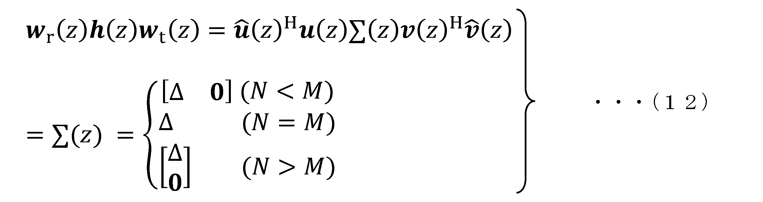
式(12)において、Δは、式(13)に示す行列であり、特異値の伝達関数λ1~q(z)を要素とする対角行列になっている。

式(13)において、q=rank[行列h(z)]であり、q≦(N,M)である。したがって、受信ビーム形成処理部26は、受信ウェイト行列wr(z)と、受信ビーム形成前のデータ信号とを乗算した結果に対して、行ごと、すなわち、ストリームごとにλ1~q(z)-1の各々を乗算する。これにより、シンボル間干渉を抑制して、ストリームごとに分離することが可能になる。送信ビーム形成処理部14が、送信ビームを形成する際に、各ストリームのλ1~q(z)-1を処理しておくことで、Δが、単位行列になるようにしておいてもよい。
受信ビーム形成処理部26は、復元したデータ信号をデータ信号復調部27に出力する。
データ信号復調部27は、受信ビーム形成処理部26が出力するデータ信号を入力する。データ信号復調部27は、入力したデータ信号を復調してビットデータを復元する(ステップS115)。送信データ検出部28は、データ信号復調部27が復調したビットデータから送信データを検出する。送信データ検出部28は、検出した送信データを外部に出力する。
上記の実施形態の無線通信システム100は、複数のアンテナ17-1~17-Mを有する無線送信局装置1と、複数のアンテナ21-1~21-Mを有する無線受信局装置2とを備える。無線受信局装置2において、通信路推定部23は、無線送信局装置1から受信するトレーニング信号に基づいて、通信路行列h(z)を推定する。送受信ウェイト算出部24は、通信路推定部23が推定した通信路行列h(z)を周波数領域に変換し、変換した周波数領域の通信路行列に対して、周波数ごとに特異値分解を行うことにより得られるユニタリ行列U(f)と随伴行列V(f)Hの各々の複素共役転置行列を時間領域に変換し、各々を受信ウェイト行列wr(z)と、送信ウェイト行列wt(z)とする。受信ビーム形成処理部26は、受信ウェイト行列wr(z)に基づいて、受信ビーム形成を行う。無線送信局装置1において、送信ビーム形成処理部14は、無線受信局装置2から受信する送信ウェイト行列wt(z)に基づいて、送信ビーム形成を行う。これにより、送信側と受信側のアンテナの本数が異なる場合、すなわち、通信路行列h(z)が非正方の行列の場合であっても、FIRフィルタ型の送信ビーム形成及び受信ビーム形成が可能となる。
また、上記の無線通信システム100では、式(12)の最後に示されるように、無線送信局装置1のアンテナ17-1~17-Mの本数「M」と、無線受信局装置2のアンテナ21-1~21-Nの本数「N」とが、同一の場合であっても、異なる場合であっても、各ストリームの利得は、各特異値の伝達関数λ1(z)~λq(z)に依存することになる。そのため、通信路行列h(z)の相関が高い場合、幾つかの特異値が0、すなわちq<min(N,M)となる。この場合、一部の特異値が0になることから、ストリームの幾つかが低スループットまたは通信不可となる可能性があるが、全てのストリームにおいて通信不可になることはない。
また、上記の無線通信システム100では、周波数領域で送信ウェイト行列wt(z)及び受信ウェイト行列wr(z)を算出しており、時間領域で送信ウェイト行列wt(z)及び受信ウェイト行列wr(z)を乗算する処理、すなわち送信ビーム、受信ビームを形成する処理を行う。そのため、時間領域での送信ビーム、受信ビームの形成の処理は、データ信号に対して逐次的に処理を行うことができるので、データ信号に対して離散フーリエ変換を行う手法を採用するよりも処理遅延を軽減することが可能となる。
上記の実施形態の送受信ウェイト算出部24における処理において、離散フーリエ変換に替えて、高速フーリエ変換を適用してもよいし、逆離散フーリエ変換に替えて、高速逆フーリエ変換を適用してもよい。
また、上記の実施形態では、無線受信局装置2が、送受信ウェイト算出部24を備えるようにしているが、無線送信局装置1が、送受信ウェイト算出部24を備えて、受信ウェイト行列wr(z)と、送信ウェイト行列wt(z)を算出するようにしてもよい。この場合、無線送信局装置1の送信信号変換部15が、送受信ウェイト算出部24から受信ウェイト行列wr(z)を受けて、無線受信局装置2に受信ウェイト行列wr(z)を送信することになる。
また、上記の実施形態では、無線送信局装置1が、トレーニング信号生成部13を備え、無線受信局装置2が、通信路推定部23を備えるようにしているが、無線受信局装置2が、トレーニング信号生成部13を備え、無線送信局装置1が、通信路推定部23を備えて、無線送信局装置1が、通信路行列h(z)を推定するようにしてもよい。この場合において、無線受信局装置2が送受信ウェイト算出部24を備える場合、無線送信局装置1の送信信号変換部15が通信路推定部23から通信路行列h(z)を受けて、無線受信局装置2に通信路行列h(z)を送信することになる。
また、上記の実施形態では、無線受信局装置2が、複数のアンテナ21-1~21-Nを備えるようにしているが、単一のアンテナ21-1を備える無線受信局装置2が、複数台あってもよいし、複数のアンテナ21-1~21-Nを備える無線受信局装置2が、複数台あってもよい。
上述した実施形態における無線送信局装置1と無線受信局装置2をコンピュータで実現するようにしてもよい。その場合、この機能を実現するためのプログラムをコンピュータ読み取り可能な記録媒体に記録して、この記録媒体に記録されたプログラムをコンピュータシステムに読み込ませ、実行することによって実現してもよい。ここでいう「コンピュータシステム」とは、OSや周辺機器等のハードウェアを含むものとする。また、「コンピュータ読み取り可能な記録媒体」とは、フレキシブルディスク、光磁気ディスク、ROM、CD-ROM等の可搬媒体、コンピュータシステムに内蔵されるハードディスク等の記憶装置のことをいう。さらに「コンピュータ読み取り可能な記録媒体」とは、インターネット等のネットワークや電話回線等の通信回線を介してプログラムを送信する場合の通信線のように、短時間の間、動的にプログラムを保持するもの、その場合のサーバやクライアントとなるコンピュータシステム内部の揮発性メモリのように、一定時間プログラムを保持しているものも含んでもよい。また上記プログラムは、前述した機能の一部を実現するためのものであってもよく、さらに前述した機能をコンピュータシステムにすでに記録されているプログラムとの組み合わせで実現できるものであってもよく、FPGA(Field Programmable Gate Array)等のプログラマブルロジックデバイスを用いて実現されるものであってもよい。
以上、この発明の実施形態について図面を参照して詳述してきたが、具体的な構成はこの実施形態に限られるものではなく、この発明の要旨を逸脱しない範囲の設計等も含まれる。
SC-MIMO伝送を行う無線通信に適用できる。
1…無線送信局装置、2…無線受信局装置、11…ビットデータ生成部、12…データ信号変調部、13…トレーニング信号生成部、14…送信ビーム形成処理部、15…送信信号変換部、16…受信信号変換部、17-1~17-M…アンテナ、21-1~21-N…アンテナ、22…受信信号変換部、23…通信路推定部、24…送受信ウェイト算出部、25…送信信号変換部、26…受信ビーム形成処理部、27…データ信号復調部、28…送信データ検出部
Claims (4)
- 複数のアンテナを有する無線送信局装置と、アンテナを有する無線受信局装置とを備え、シングルキャリアによって無線信号の送受信を行う無線通信システムにおける無線通信方法であって、
前記無線受信局装置、または、前記無線送信局装置が、トレーニング信号に基づいて、通信路行列を推定し、
前記無線受信局装置、または、前記無線送信局装置が、推定した前記通信路行列を周波数領域に変換し、変換した周波数領域の通信路行列に対して、周波数ごとに特異値分解を行うことにより得られるユニタリ行列と随伴行列の各々の複素共役転置行列を時間領域に変換し、各々を受信ウェイト行列と、送信ウェイト行列とし、
前記無線送信局装置が、前記送信ウェイト行列に基づいて、送信ビーム形成を行い、
前記無線受信局装置が、前記受信ウェイト行列に基づいて、受信ビーム形成を行う、
無線通信方法。 - 前記無線受信局装置は、複数のアンテナを有する単一の無線受信局装置であるか、または、単一または複数のアンテナを有する複数の無線受信局装置である、
請求項1に記載の無線通信方法。 - 前記無線送信局装置のアンテナの本数と、前記無線受信局装置のアンテナの本数が異なる、
請求項1または2に記載の無線通信方法。 - 複数のアンテナを有する無線送信局装置と、アンテナを有する無線受信局装置とを備え、シングルキャリアによって無線信号の送受信を行う無線通信システムであって、
前記無線受信局装置、または、前記無線送信局装置は、
トレーニング信号に基づいて、通信路行列を推定する通信路推定部を備え、
前記無線受信局装置、または、前記無線送信局装置は、
前記通信路推定部が推定した前記通信路行列を周波数領域に変換し、変換した周波数領域の通信路行列に対して、周波数ごとに特異値分解を行うことにより得られるユニタリ行列と随伴行列の各々の複素共役転置行列を時間領域に変換し、各々を受信ウェイト行列と、送信ウェイト行列とする送受信ウェイト算出部を備え、
前記無線受信局装置は、
前記受信ウェイト行列に基づいて、受信ビーム形成を行う受信ビーム形成処理部、
を備え、
前記無線送信局装置は、
前記無線受信局装置から受信する前記送信ウェイト行列に基づいて、送信ビーム形成を行う送信ビーム形成処理部、
を備える無線通信システム。
Priority Applications (3)
| Application Number | Priority Date | Filing Date | Title |
|---|---|---|---|
| JP2022507985A JPWO2021186699A1 (ja) | 2020-03-19 | 2020-03-19 | |
| PCT/JP2020/012417 WO2021186699A1 (ja) | 2020-03-19 | 2020-03-19 | 無線通信方法及び無線通信システム |
| US17/909,206 US12199710B2 (en) | 2020-03-19 | 2020-03-19 | Wireless communication method and wireless communication system |
Applications Claiming Priority (1)
| Application Number | Priority Date | Filing Date | Title |
|---|---|---|---|
| PCT/JP2020/012417 WO2021186699A1 (ja) | 2020-03-19 | 2020-03-19 | 無線通信方法及び無線通信システム |
Publications (1)
| Publication Number | Publication Date |
|---|---|
| WO2021186699A1 true WO2021186699A1 (ja) | 2021-09-23 |
Family
ID=77771904
Family Applications (1)
| Application Number | Title | Priority Date | Filing Date |
|---|---|---|---|
| PCT/JP2020/012417 Ceased WO2021186699A1 (ja) | 2020-03-19 | 2020-03-19 | 無線通信方法及び無線通信システム |
Country Status (3)
| Country | Link |
|---|---|
| US (1) | US12199710B2 (ja) |
| JP (1) | JPWO2021186699A1 (ja) |
| WO (1) | WO2021186699A1 (ja) |
Families Citing this family (2)
| Publication number | Priority date | Publication date | Assignee | Title |
|---|---|---|---|---|
| JP7513123B2 (ja) * | 2021-01-26 | 2024-07-09 | 日本電信電話株式会社 | 通信路推定方法および無線通信装置 |
| WO2023162104A1 (ja) * | 2022-02-24 | 2023-08-31 | 日本電信電話株式会社 | 電波の到来方向推定装置、及び電波の到来方向推定方法 |
Citations (2)
| Publication number | Priority date | Publication date | Assignee | Title |
|---|---|---|---|---|
| JP2016500942A (ja) * | 2012-09-28 | 2016-01-14 | インターデイジタル パテント ホールディングス インコ | WiFiビームフォーミング、フィードバックおよびサウンディング(WiBEAM)のための方法 |
| US20190319677A1 (en) * | 2018-04-13 | 2019-10-17 | Peraso Technologies Inc. | Single-carrier wideband beamforming method and system |
Family Cites Families (4)
| Publication number | Priority date | Publication date | Assignee | Title |
|---|---|---|---|---|
| JP4546177B2 (ja) | 2003-07-28 | 2010-09-15 | パナソニック株式会社 | 無線通信装置および無線通信方法 |
| BRPI0617044A2 (pt) * | 2005-09-29 | 2011-07-12 | Interdigital Tech Corp | sistema de múltiplo acesso por divisão de freqüências e portadora única com base em formação de feixes mimo |
| JP4775288B2 (ja) * | 2006-04-27 | 2011-09-21 | ソニー株式会社 | 無線通信システム、無線通信装置及び無線通信方法 |
| JP5897810B2 (ja) | 2011-03-29 | 2016-03-30 | シャープ株式会社 | 基地局装置、端末装置、通信システム、通信方法 |
-
2020
- 2020-03-19 WO PCT/JP2020/012417 patent/WO2021186699A1/ja not_active Ceased
- 2020-03-19 JP JP2022507985A patent/JPWO2021186699A1/ja active Pending
- 2020-03-19 US US17/909,206 patent/US12199710B2/en active Active
Patent Citations (2)
| Publication number | Priority date | Publication date | Assignee | Title |
|---|---|---|---|---|
| JP2016500942A (ja) * | 2012-09-28 | 2016-01-14 | インターデイジタル パテント ホールディングス インコ | WiFiビームフォーミング、フィードバックおよびサウンディング(WiBEAM)のための方法 |
| US20190319677A1 (en) * | 2018-04-13 | 2019-10-17 | Peraso Technologies Inc. | Single-carrier wideband beamforming method and system |
Also Published As
| Publication number | Publication date |
|---|---|
| US20230106272A1 (en) | 2023-04-06 |
| JPWO2021186699A1 (ja) | 2021-09-23 |
| US12199710B2 (en) | 2025-01-14 |
Similar Documents
| Publication | Publication Date | Title |
|---|---|---|
| US11038636B2 (en) | Modulation and equalization in an orthonormal time-frequency shifting communications system | |
| US10637697B2 (en) | Modulation and equalization in an orthonormal time-frequency shifting communications system | |
| US9900048B2 (en) | Modulation and equalization in an orthonormal time-frequency shifting communications system | |
| KR101061082B1 (ko) | Mimo 시스템에서 수신기의 성능을 향상시키기 위한 신호의 스케일링 방법 및 장치 | |
| US9071285B2 (en) | Modulation and equalization in an orthonormal time-frequency shifting communications system | |
| US9590779B2 (en) | Modulation and equalization in an orthonormal time-frequency shifting communications system | |
| US10924170B2 (en) | Smoothing beamforming matrices across sub-carriers | |
| US20060294170A1 (en) | Diversity receiver device | |
| JP2015525986A (ja) | 時間周波数偏移通信システムにおける変調および等化 | |
| US12375336B2 (en) | Modulation and equalization in an orthonormal time-shifting communications system | |
| JP7180514B2 (ja) | 無線通信システム、無線通信方法、送信局装置および受信局装置 | |
| CN101682460A (zh) | 接收装置和接收方法 | |
| JPWO2019172412A1 (ja) | 無線装置及びチャネル予測方法 | |
| EP1349297A1 (en) | A closed loop multiple antenna system | |
| JP7284445B2 (ja) | 無線通信方法及び無線通信システム | |
| CN106716866A (zh) | 乒乓波束成形 | |
| JP5859913B2 (ja) | 無線受信装置、無線送信装置、無線通信システム、プログラムおよび集積回路 | |
| US12199710B2 (en) | Wireless communication method and wireless communication system | |
| JP6166641B2 (ja) | 重み係数算出装置、アダプティブアレー受信装置、及び、重み係数算出方法 | |
| JP2014060616A (ja) | 通信装置、および信号検出方法 | |
| US8179315B1 (en) | Iterative technique for fast computation of TxBF steering weights | |
| US7583748B2 (en) | Frequency-domain method for joint equalization and decoding of space-time block codes | |
| JP5669046B2 (ja) | 無線信号の受信方法及び受信装置 | |
| CN108496310B (zh) | 一种信号解码方法、装置及设备 | |
| JP4310333B2 (ja) | 復号装置及び復号方法、及びmimo無線通信システム |
Legal Events
| Date | Code | Title | Description |
|---|---|---|---|
| 121 | Ep: the epo has been informed by wipo that ep was designated in this application |
Ref document number: 20925650 Country of ref document: EP Kind code of ref document: A1 |
|
| ENP | Entry into the national phase |
Ref document number: 2022507985 Country of ref document: JP Kind code of ref document: A |
|
| NENP | Non-entry into the national phase |
Ref country code: DE |
|
| 122 | Ep: pct application non-entry in european phase |
Ref document number: 20925650 Country of ref document: EP Kind code of ref document: A1 |