WO2021186684A1 - 通信システム - Google Patents
通信システム Download PDFInfo
- Publication number
- WO2021186684A1 WO2021186684A1 PCT/JP2020/012366 JP2020012366W WO2021186684A1 WO 2021186684 A1 WO2021186684 A1 WO 2021186684A1 JP 2020012366 W JP2020012366 W JP 2020012366W WO 2021186684 A1 WO2021186684 A1 WO 2021186684A1
- Authority
- WO
- WIPO (PCT)
- Prior art keywords
- optical
- splitter
- optical signal
- olt
- onu
- Prior art date
- Legal status (The legal status is an assumption and is not a legal conclusion. Google has not performed a legal analysis and makes no representation as to the accuracy of the status listed.)
- Ceased
Links
Images


Classifications
-
- H—ELECTRICITY
- H04—ELECTRIC COMMUNICATION TECHNIQUE
- H04Q—SELECTING
- H04Q11/00—Selecting arrangements for multiplex systems
- H04Q11/0001—Selecting arrangements for multiplex systems using optical switching
- H04Q11/0062—Network aspects
- H04Q11/0067—Provisions for optical access or distribution networks, e.g. Gigabit Ethernet Passive Optical Network (GE-PON), ATM-based Passive Optical Network (A-PON), PON-Ring
-
- H—ELECTRICITY
- H04—ELECTRIC COMMUNICATION TECHNIQUE
- H04L—TRANSMISSION OF DIGITAL INFORMATION, e.g. TELEGRAPHIC COMMUNICATION
- H04L12/00—Data switching networks
- H04L12/28—Data switching networks characterised by path configuration, e.g. LAN [Local Area Networks] or WAN [Wide Area Networks]
- H04L12/42—Loop networks
- H04L12/437—Ring fault isolation or reconfiguration
-
- H—ELECTRICITY
- H04—ELECTRIC COMMUNICATION TECHNIQUE
- H04Q—SELECTING
- H04Q11/00—Selecting arrangements for multiplex systems
- H04Q11/0001—Selecting arrangements for multiplex systems using optical switching
- H04Q11/0062—Network aspects
- H04Q2011/009—Topology aspects
- H04Q2011/0096—Tree
Definitions
- the present invention relates to a communication system technology.
- PON Passive Optical Network
- a terminal device and a plurality of terminal devices are connected (for example, non-stationary device).
- PON is a point-to-multipoint network in which stations provide services to a large number of subscribers.
- the downlink optical signal from the station is branched by an optical coupler connected to one trunk fiber and distributed to a plurality of subscribers.
- an ONU optical network unit
- OLT optical line terminal unit: Optical Line Terminal
- an object of the present invention is to provide a technique capable of increasing the possibility of maintaining communication even when a failure occurs in the PON.
- One aspect of the present invention includes an OLT (optical network unit: Optical Line Terminal) and a first splitter that outputs an optical signal output from the OLT from a first port and a second port to an optical communication path.
- the first port and the second port of the first splitter are connected to a plurality of second splitters connected by using an optical communication path, and the second splitter and the second splitter are connected by using an optical communication path.
- It is a communication system of a passive optical communication network equipped with an ONU (optical network unit: Optical Network Unit).
- FIG. 1 is a diagram showing a system configuration example of the communication system 100 of the present invention.
- the communication system 100 includes a higher-level device 10, an OLT 20, a first splitter 21, a plurality of second splitters 30, a plurality of ONUs 40, a lower-level device 50, and a user device 60.
- the host device 10 is connected to the host network of the communication system 100.
- the first splitter 21 and the plurality of second splitters 30 are connected to a communication line (hereinafter referred to as "main line communication line”) configured in a ring shape.
- main line communication line a communication line
- the number of the second splitter 30 and the ONU 40 is three, but the number “3” is only a specific example. That is, the number of the second splitter 30 and the ONU 40 may be any number as long as it is two or more.
- the OLT 20 is installed so as to be able to communicate with the host device 10.
- the OLT 20 functions as an OLT in PON.
- the first splitter 21 receives an optical signal input from the OLT 20 and outputs the optical signal to the main communication path through a plurality of paths.
- the first splitter 21 receives input of optical signals from the main communication path through a plurality of paths, aggregates the optical signals, and outputs the optical signals to the OLT 20.
- the second splitter 30 receives the input of the optical signal and outputs the optical signal to a plurality of paths.
- the second splitter 30 is configured by using, for example, a 2-input 2-output optical splitter.
- the ONU 40 is connected to the lower device 50 so as to be able to communicate with each other.
- the lower device 50 is communicably connected to one or more user devices 60.
- each device will be described in detail. However, for convenience of explanation, the upper device 10, the lower device 50, and the user device 60 will be described before the description of the OLT 20, the first splitter 21, the second splitter 30, and the ONU 40.
- the upper device 10 is communicably connected to a plurality of lower devices 50 via the OLT 20, the first splitter 21, the second splitter 30, and the ONU 40.
- the upper device 10 is a device that realizes a predetermined function by communicating with a plurality of lower devices 50.
- the host device 10 is, for example, a base station device (BBU: Base Band Unit) in a mobile network.
- BBU Base Band Unit
- the host device 10 may be, for example, a communication device constituting a relay network.
- the lower device 50 is a device that realizes a predetermined function by communicating with the higher device 10.
- the lower device 50 is a device installed at a position closer to the user side than the upper device 10.
- the upper device 10 is a BBU
- the lower device 50 is a wireless device (RRH: Remote Radio Head) in the mobile network.
- the communication path between the lower device 50 and the user device 60 is an access section of the mobile network.
- the upper device 10 is a communication device constituting a relay network
- the lower device 50 may be a device such as a set-top box.
- the communication path between the lower device 50 and the user device 60 may be a network such as a home network.
- the lower device 50 accommodates, for example, one or more user devices 60.
- the user device 60 may be connected to the ONU 40 without going through the lower device 50.
- the user device 60 is a device that is communicably connected to another device by connecting to the lower device 50 via a communication path.
- the user device 60 is an information processing device such as a smartphone, a tablet, or a personal computer.
- the user device 60 may be, for example, a sensor in IoT (Internet of Things).
- the user device 60 may be a device for business use such as an ATM (Automatic Teller Machine), a vending machine, or a POS (Point Of Sale) terminal.
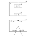
- FIG. 2 is a diagram showing a configuration example of the OLT 20 and the first splitter 21.
- the OLT 20 includes an optical interface 201 and a signal processing unit 202.
- the OLT 20 is a device that provides an OLT function in a conventional PON.
- the optical interface 201 outputs the optical signal generated by the signal processing unit 202 to the first splitter 21.
- the optical interface 201 transmits an optical signal to the ONU 40 via the first splitter 21 and the second splitter 30.
- An optical signal addressed to a plurality of ONU 40s may be superimposed on the optical signal transmitted by the optical interface 201.
- the optical interface 201 receives an optical signal from the first splitter 21 and outputs the received optical signal to the signal processing unit 202.
- the optical interface 201 receives an optical signal from the ONU 40 via the second splitter 30 and the first splitter 21.
- Optical signals transmitted from a plurality of ONU 40s may be superimposed on the optical signals received by the optical interface 201.
- the signal processing unit 202 functions as a conventional OLT. Hereinafter, an example of such processing by the signal processing unit 202 will be described.
- the signal processing unit 202 converts the electric signal transmitted from the higher-level device 10 to the lower-level device 50 into an optical signal and outputs it to the optical interface 201.
- the signal processing unit 202 may superimpose (multiplex) optical signals addressed to a plurality of lower-level devices 50.
- the signal processing unit 202 converts the optical signal received by the optical interface 201 into an electric signal, and outputs the electric signal to the host device 10 which is the destination.
- the first splitter 21 is configured by using a splitter for an optical signal.
- the first splitter 21 includes at least three ports (211, 212 and 213).
- the first splitter 21 distributes and outputs an optical signal input from the OLT 20 via the port 211 to a plurality of ports (port 212 and port 213) connected to the main communication path.
- the ratio of the optical signals distributed to the port 212 and the port 213 may be a geometric progression (50:50) or an unequal ratio (eg 40:60).
- the first splitter 21 aggregates and outputs a plurality of optical signals input from the main communication path via the port 212 and the port 213 to the port 211 connected to the OLT 20.
- FIG. 3 is a diagram showing a configuration example of the second splitter 30 and the ONU 40.
- the second splitter 30 is configured by using a two-input, two-output second splitter for an optical signal.
- the second splitter 30 distributes and outputs an optical signal input from the main communication path to a subsequent device and an ONU 40 connected to the own device.
- the distribution ratio at this time may be a geometric progression (50:50) or an unequal ratio (for example, 40:60).
- the device in the latter stage is a device different from the device from which the optical signal input to the own device is output, out of the two devices connected to the own device via the main communication path.
- the device in the subsequent stage when looking at the second splitter 30-1 as a reference, when the optical signal input from the first splitter 21 is distributed, the device in the subsequent stage is the second splitter 30-2.
- the device in the subsequent stage when looking at the second splitter 30-2 as a reference, when the optical signal input from the second splitter 30-1 is distributed, the device in the subsequent stage is the second splitter 30-3.
- the device in the subsequent stage is the second splitter 30-1.
- the second splitter 30 outputs an optical signal output to the ONU 40 connected to its own device to the ONU 40 by a different communication path depending on the input port.
- the second splitter 30 outputs an optical signal input from the upper left of FIG. 3 to the upper right and the lower right. Therefore, to explain the second splitter 30-1 of FIG. 1 as an example, the optical signal input from the first splitter 21 is output to the path 91-2 and the second splitter 30-2.
- the optical signal output to path 91-2 is input to ONU40-1.
- the second splitter 30 outputs an optical signal input from the upper right of FIG. 3 to the upper left and the lower left. Therefore, to explain the second splitter 30-1 of FIG.
- the optical signal input from the second splitter 30-2 is output to the path 91-1 and the first splitter 21.
- the optical signal output to the path 91-1 is input to the ONU40-1.
- the path 91-1 and the path 91-2 are connected to different optical meters. For example, path 91-1 is connected to the first optical meter 41, and path 91-2 is connected to the second optical meter 42.
- the ONU 40 includes a first optical meter 41, a second optical meter 42, an optical switch 43, a control unit 44, a signal processing unit 45, and a communication unit 46.
- the first optical meter 41 receives the optical signal output from the second splitter 30.
- the first optical meter 41 outputs information indicating the light intensity of the received optical signal to the control unit 44.
- the first optical meter 41 outputs the received optical signal to the optical switch 43.
- the second optical meter 42 receives the optical signal output from the second splitter 30.
- the second optical meter 42 outputs information indicating the light intensity of the received optical signal to the control unit 44.
- the second optical meter 42 outputs the received optical signal to the optical switch 43.
- the optical switch 43 outputs either an optical signal output from the first optical meter 41 or an optical signal output from the second optical meter 42 to the signal processing unit 45 according to the control of the control unit 44. ..
- the optical switch 43 outputs an optical signal output from the signal processing unit 45 to the second splitter 30 via either the first optical meter 41 or the second optical meter 42 under the control of the control unit 44.
- the control unit 44 receives light intensity information from the first optical meter 41 and the second optical meter 42, respectively, and selects one of the optical signals according to a predetermined standard.
- the control unit 44 controls the optical switch 43 so that the selected optical signal is output to the signal processing unit 45.
- a predetermined criterion at the time of selection is, for example, higher reliability.
- the high reliability may be determined based on the light intensity of the optical signal.
- the control unit 44 may select an optical signal having a stronger light intensity.
- Part or all of the operation of the control unit 44 is, for example, an electronic circuit using an LSI (Large Scale Integration circuit), an ASIC (Application Specific Integrated Circuit), a PLD (Programmable Logic Device), an FPGA (Field Programmable Gate Array), or the like. It may be realized using hardware including (electronic circuit or circuitry).
- the signal processing unit 45 functions as an ONU in a conventional PON. Hereinafter, an example of such processing by the signal processing unit 45 will be described.
- the signal processing unit 45 converts an optical signal indicating a signal transmitted from the higher-level device 10 to the lower-level device 50 into an electric signal and outputs it to the communication unit 46.
- the optical signals addressed to the plurality of lower devices 50 are superimposed (multiplexed)
- the optical signals addressed to the lower devices 50 connected to the own device (ONU40) are taken out from the optical signals and then electric. Convert to a signal.
- the signal processing unit 45 converts the electric signal received by the communication unit 46 into an optical signal and outputs it to the optical switch 43.
- the communication unit 46 is a communication interface for communicating with the lower device 50.
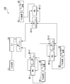
- FIG. 4 is a diagram showing a specific example of the operation of the communication system 100 during normal communication.
- the arrow shown in FIG. 4 indicates the flow of the downlink signal (the signal flowing from the upper device 10 to the lower device 50).
- the first splitter 21 is arranged between the OLT 20 and the main line communication path, so that the downlink signal is transmitted in both clockwise and counterclockwise paths. NS.
- each downlink signal branched by the first splitter 21 reaches the first splitter 21 via all the second splitters 30.
- each ONU 40 is reached by an optical signal transmitted clockwise on the main line communication path and an optical signal transmitted counterclockwise on the main line communication line.
- Each ONU 40 selects one of the optical signals according to a predetermined reference (for example, the one having a stronger light intensity) and uses it for processing.
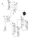
- FIG. 5 is a diagram showing a specific example of the operation of the communication system 100 at the time of fault communication.
- the one indicated by the broken line indicates the communication path through which the optical signal (downlink signal) transmitted from the OLT 20 does not pass.
- What is indicated by a solid line with an arrow indicates a communication path through which an optical signal (downlink signal) transmitted from the OLT 20 passes.
- the second splitter 30-2 cannot receive the optical signal transmitted clockwise due to the occurrence of a failure, but receives the optical signal transmitted counterclockwise.
- the ONU 40-2 receives an optical signal transmitted counterclockwise via the second splitter 30-2.
- the second splitter 30-3 cannot receive the optical signal transmitted counterclockwise due to the occurrence of a failure, but receives the optical signal transmitted clockwise.
- the ONU 40-3 receives an optical signal transmitted clockwise via the second splitter 30-3.
- all ONUs (ONU40-1, ONU40-2 and ONU40-3) can receive the downlink signal from the OLT 20 and can maintain the communication regardless of the occurrence of the failure.
- the uplink signal is transmitted from each ONU40 to the OLT 20 by flowing the signal in the opposite direction of the arrow via the solid line path in each of the above figures. Further, in FIGS. 4 and 5, the arrow between the second splitter 30 and the ONU 40 points in only one direction, and this arrow indicates the direction of the downlink signal. In the case of an uplink signal, the signal is transmitted using the path selected by the optical switch 43.
- the optical signal output from the OLT 20 is distributed to a plurality of paths by the first splitter 21 and transmitted through the main communication path.
- the downlink signal is transmitted through two routes, a clockwise route and a counterclockwise route.
- the present invention is applicable to a system that communicates using PON.
Landscapes
- Engineering & Computer Science (AREA)
- Computer Networks & Wireless Communication (AREA)
- Small-Scale Networks (AREA)
- Signal Processing (AREA)
- Optical Communication System (AREA)
Abstract
本発明の一態様は、OLT(光加入者線端局装置:Optical Line Terminal)と、前記OLTから出力される光信号を第一ポート及び第二ポートから光通信路に出力する第一スプリッターと、前記第一スプリッターの前記第一ポートと前記第二ポートとの間を、光通信路を用いて接続された複数の第二スプリッターと、前記第二スプリッターと光通信路を用いて接続されたONU(光回線終端装置:Optical Network Unit)と、を備えた、受動光通信網の通信システムである。
Description
本発明は、通信システムの技術に関する。
光アクセスを提供するサービスにおいて、端局装置と複数の終端装置とが接続された受動光通信網(PON:Passive Optical Network)を用いることによって、経済的なサービス提供が実現されている(例えば非特許文献1参照)。PONは、局が多数の加入者にサービスを提供するポイントツーマルチポイントネットワークである。例えば、PONでは、局からの下り光信号が1本の幹線ファイバに繋がる光カプラで分岐され、複数の加入者に分配される。PONでは、下位側のONU(光回線終端装置:Optical Network Unit)と、上位側のOLT(光加入者線端局装置:Optical Line Terminal)と、が用いられる。
しかしながら、従来のPONでは、設備の故障等の障害が生じた場合に、通信を維持することが難しいという問題があった。
上記事情に鑑み、本発明は、PONにおいて障害が生じた場合であっても通信を維持できる可能性を高くすることができる技術の提供を目的としている。
上記事情に鑑み、本発明は、PONにおいて障害が生じた場合であっても通信を維持できる可能性を高くすることができる技術の提供を目的としている。
本発明の一態様は、OLT(光加入者線端局装置:Optical Line Terminal)と、前記OLTから出力される光信号を第一ポート及び第二ポートから光通信路に出力する第一スプリッターと、前記第一スプリッターの前記第一ポートと前記第二ポートとの間を、光通信路を用いて接続された複数の第二スプリッターと、前記第二スプリッターと光通信路を用いて接続されたONU(光回線終端装置:Optical Network Unit)と、を備えた、受動光通信網の通信システムである。
本発明により、PONにおいて障害が生じた場合であっても通信を維持できる可能性を高くすることが可能となる。
本発明の実施形態について、図面を参照して詳細に説明する。
図1は、本発明の通信システム100のシステム構成例を示す図である。通信システム100は、上位装置10、OLT20、第一スプリッター21、複数の第二スプリッター30、複数のONU40、下位装置50及びユーザー装置60を備える。上位装置10は、通信システム100の上位ネットワークに接続される。第一スプリッター21及び複数の第二スプリッター30は、リング状に構成された通信路(以下「幹線通信路」という。)に接続される。図1では、第二スプリッター30及びONU40の台数が3台であるが、この“3”という数字は具体例にすぎない。すなわち、第二スプリッター30及びONU40の台数は、2台以上であれば何台であってもよい。
図1は、本発明の通信システム100のシステム構成例を示す図である。通信システム100は、上位装置10、OLT20、第一スプリッター21、複数の第二スプリッター30、複数のONU40、下位装置50及びユーザー装置60を備える。上位装置10は、通信システム100の上位ネットワークに接続される。第一スプリッター21及び複数の第二スプリッター30は、リング状に構成された通信路(以下「幹線通信路」という。)に接続される。図1では、第二スプリッター30及びONU40の台数が3台であるが、この“3”という数字は具体例にすぎない。すなわち、第二スプリッター30及びONU40の台数は、2台以上であれば何台であってもよい。
OLT20は、上位装置10と通信可能に設置される。OLT20は、PONにおけるOLTとして機能する。第一スプリッター21は、OLT20から光信号の入力を受け、複数の経路で幹線通信路へ光信号を出力する。第一スプリッター21は、複数の経路で幹線通信路から光信号の入力を受け、光信号を集約してOLT20に出力する。第二スプリッター30は、光信号の入力を受け、複数の経路へ光信号を出力する。第二スプリッター30は、例えば2入力2出力光スプリッターを用いて構成される。
ONU40は、それぞれ下位装置50に通信可能に接続される。下位装置50は、1又は複数のユーザー装置60に通信可能に接続される。以下、各装置について詳細に説明する。ただし、説明の便宜のため、OLT20、第一スプリッター21、第二スプリッター30及びONU40についての説明よりも先に、上位装置10、下位装置50及びユーザー装置60について説明する。
上位装置10は、OLT20、第一スプリッター21、第二スプリッター30及びONU40を介して、複数の下位装置50と通信可能に接続される。上位装置10は、複数の下位装置50との間で通信を行うことによって所定の機能を実現する装置である。上位装置10は、例えばモバイル網における基地局装置(BBU:Base Band Unit)である。上位装置10は、例えば中継網を構成する通信機器であってもよい。
下位装置50は、上位装置10との間で通信を行うことによって所定の機能を実現する装置である。下位装置50は、上位装置10に比べてよりユーザー側に近い位置に設置される装置である。例えば上位装置10がBBUである場合、下位装置50はモバイル網における無線装置(RRH:Remote Radio Head)である。この場合、下位装置50とユーザー装置60との間の通信路は、モバイル網のアクセス区間となる。一方、上位装置10が中継網を構成する通信機器である場合には、下位装置50はセットトップボックス等の装置であってもよい。この場合、下位装置50とユーザー装置60との間の通信路は、ホームネットワーク等のネットワークであってもよい。下位装置50は、例えば1又は複数のユーザー装置60を収容する。なお、下位装置50を介さずにユーザー装置60がONU40に接続されてもよい。
ユーザー装置60は、下位装置50に通信路を介して接続することによって、他の装置と通信可能に接続される装置である。ユーザー装置60は、例えばスマートフォン、タブレット、パーソナルコンピュータ等の情報処理装置である。ユーザー装置60は、例えばIoT(Internet of Things)におけるセンサであってもよい。ユーザー装置60は、例えばATM(Automatic Teller Machine)や自動販売機やPOS(Point Of Sale)端末等のビジネス用途の装置であってもよい。
次に、OLT20及び第一スプリッター21について説明する。図2は、OLT20及び第一スプリッター21の構成例を示す図である。OLT20は、光インターフェース201及び信号処理部202を備える。OLT20は、従来のPONにおけるOLT機能を提供する装置である。
光インターフェース201は、信号処理部202によって生成された光信号を第一スプリッター21に出力する。光インターフェース201は、第一スプリッター21及び第二スプリッター30を介してONU40に光信号を送信する。光インターフェース201によって送信される光信号には、複数のONU40宛の光信号が重畳されていてもよい。
光インターフェース201は、第一スプリッター21から光信号を受信し、受信された光信号を信号処理部202に出力する。光インターフェース201は、第二スプリッター30及び第一スプリッター21を介してONU40から光信号を受信する。光インターフェース201によって受信される光信号には、複数のONU40から送信された光信号が重畳されていてもよい。
信号処理部202は、従来のOLTとして機能を行う。以下、このような信号処理部202の処理の一例について説明する。信号処理部202は、上位装置10から下位装置50宛に送信された電気信号を光信号に変換し、光インターフェース201に出力する。信号処理部202は、複数の下位装置50宛の光信号を重畳(多重化)させてもよい。信号処理部202は、光インターフェース201によって受信された光信号を電気信号に変換し、宛先となっている上位装置10に電気信号を出力する。
第一スプリッター21は、光信号用のスプリッターを用いて構成される。第一スプリッター21は、少なくとも3つのポート(211、212及び213)を備える。第一スプリッター21は、OLT20からポート211を介して入力される光信号を、幹線通信路に繋がる複数のポート(ポート212及びポート213)に分配して出力する。ポート212及びポート213に分配される光信号の比は、等比(50:50)であってもよいし、不等比(例えば40:60)であってもよい。第一スプリッター21は、幹線通信路からポート212及びポート213を介して入力される複数の光信号を、OLT20に繋がるポート211に集約して出力する。
図3は、第二スプリッター30及びONU40の構成例を示す図である。第二スプリッター30は、光信号用の2入力2出力の第二スプリッターを用いて構成される。第二スプリッター30は、幹線通信路から入力される光信号を、後段の装置と、自装置に接続されているONU40と、に分配して出力する。このときの分配比は、等比(50:50)であってもよいし、不等比(例えば40:60)であってもよい。
後段の装置とは、幹線通信路を介して自装置に接続されている2つの装置のうち、自装置に入力された光信号の出力元の装置とは異なる装置である。例えば、図1において、第二スプリッター30-1を基準にみると、第一スプリッター21から入力された光信号を分配する場合には、後段の装置は第二スプリッター30-2である。例えば、図1において、第二スプリッター30-2を基準にみると、第二スプリッター30-1から入力された光信号を分配する場合には、後段の装置は第二スプリッター30-3である。例えば、図1において、第二スプリッター30-2を基準にみると、第二スプリッター30-3から入力された光信号を分配する場合には、後段の装置は第二スプリッター30-1である。
また、第二スプリッター30は、自装置に接続されているONU40に出力される光信号を、入力されたポートに応じて異なる通信路でONU40に出力する。例えば、第二スプリッター30は、図3の左上から入ってきた光信号を、右上と右下とに出力する。そのため、図1の第二スプリッター30-1を例に説明すると、第一スプリッター21から入ってきた光信号は、経路91-2及び第二スプリッター30-2へ出力される。経路91-2に出力された光信号は、ONU40-1に入力する。また、例えば第二スプリッター30は、図3の右上から入ってきた光信号を、左上と左下とに出力する。そのため、図1の第二スプリッター30-1を例に説明すると、第二スプリッター30-2から入ってきた光信号は、経路91-1及び第一スプリッター21へ出力される。経路91-1に出力された光信号は、ONU40-1に入力する。なお、経路91-1と経路91-2とは、それぞれ異なる光メーターに接続される。例えば、経路91-1は第一光メーター41に接続され、経路91-2は第二光メーター42に接続される。
ONU40は、第一光メーター41、第二光メーター42、光スイッチ43、制御部44、信号処理部45及び通信部46を備える。第一光メーター41は、第二スプリッター30から出力された光信号を受信する。第一光メーター41は、受信された光信号の光強度を示す情報を制御部44に出力する。第一光メーター41は、受信された光信号を光スイッチ43に出力する。第二光メーター42は、第二スプリッター30から出力された光信号を受信する。第二光メーター42は、受信された光信号の光強度を示す情報を制御部44に出力する。第二光メーター42は、受信された光信号を光スイッチ43に出力する。
光スイッチ43は、制御部44の制御に従って、第一光メーター41から出力される光信号と、第二光メーター42から出力される光信号と、のどちらか一方を信号処理部45に出力する。光スイッチ43は、制御部44の制御に従って、信号処理部45から出力される光信号を、第一光メーター41又は第二光メーター42のいずれかを介して第二スプリッター30に出力する。
制御部44は、第一光メーター41と第二光メーター42とからそれぞれ光強度の情報を受け、所定の基準に従ってどちらか一方の光信号を選択する。制御部44は、選択された光信号が信号処理部45に出力されるように光スイッチ43を制御する。選択時の所定の基準は、例えばより信頼度が高いことである。信頼度の高さは、光信号の光強度に基づいて判定されてもよい。例えば、制御部44は、より強い光強度をもった光信号を選択してもよい。
制御部44の動作の一部又は全部は、例えば、LSI(Large Scale Integration circuit)、ASIC(Application Specific Integrated Circuit)、PLD(Programmable Logic Device)又はFPGA(Field Programmable Gate Array)等を用いた電子回路(electronic circuit又はcircuitry)を含むハードウェアを用いて実現されてもよい。
信号処理部45は、従来のPONにおけるONUとして機能を行う。以下、このような信号処理部45の処理の一例について説明する。信号処理部45は、上位装置10から下位装置50宛に送信された信号を示す光信号を電気信号に変換し、通信部46に出力する。このとき、複数の下位装置50宛の光信号が重畳(多重化)されている場合には、その中から自装置(ONU40)に接続されている下位装置50宛の光信号を取り出してから電気信号に変換する。信号処理部45は、通信部46によって受信された電気信号を光信号に変換し、光スイッチ43に出力する。
通信部46は、下位装置50との間で通信する通信インターフェースである。
通信部46は、下位装置50との間で通信する通信インターフェースである。
図4は、通常通信時における通信システム100の動作の具体例を示す図である。図4で示される矢印は、下り信号(上位装置10から下位装置50へ流れる信号)の流れを示す。図4に示されるように、通信システム100では、第一スプリッター21がOLT20と幹線通信路との間に配置されることにより、時計回りと反時計回りとの両方の経路で下り信号が送信される。
図4の例では、通信システム100において特に障害は生じていない。そのため、第一スプリッター21によって分岐された各下り信号は、全ての第二スプリッター30を経由して第一スプリッター21に到達する。その結果、各ONU40には、幹線通信路を時計回りで伝わってきた光信号と、幹線通信路を反時計回りで伝わってきた光信号と、が到達する。各ONU40は、所定の基準(例えば光強度の強い方)にしたがっていずれか一方の光信号を選択して処理に用いる。
図5は、障害通信時における通信システム100の動作の具体例を示す図である。図5において、第二スプリッター30からONU40に伸びている2本の通信路のうち、破線で示されるものは、OLT20から送信された光信号(下り信号)が通っていない通信路を示す。矢印を有する実線で示されるものは、OLT20から送信された光信号(下り信号)が通っている通信路を示す。
図5の例では、第二スプリッター30-2と第二スプリッター30-3との間の通信路において障害が生じている。そのため、第二スプリッター30-2から出力される下り信号は、第二スプリッター30-3に到達しない。同様に、第二スプリッター30-3から出力される下り信号は、第二スプリッター30-2に到達しない。
第二スプリッター30-2は、障害の発生により、時計回りに伝わっている光信号を受信することはできないが、反時計回りに伝わっている光信号を受信する。ONU40-2は、第二スプリッター30-2を介して、反時計回りに伝わっている光信号を受信する。
第二スプリッター30-3は、障害の発生により、反時計回りに伝わっている光信号を受信することはできないが、時計回りに伝わっている光信号を受信する。ONU40-3は、第二スプリッター30-3を介して、時計回りに伝わっている光信号を受信する。
以上のような動作により、障害の発生にかかわらず、全てのONU(ONU40-1、ONU40-2及びONU40-3)はOLT20から下り信号を受信でき、通信を維持することができる。
なお、下り信号の流れについて説明したが、上り信号は上記各図の実線の経路を経由して矢印の向きの反対に信号が流れることによって各ONU40からOLT20に送信される。また、図4及び図5では、第二スプリッター30とONU40との間の矢印が一方のみに向いているが、この矢印は下り信号の向きを示している。上り信号の場合には、光スイッチ43によって選択されている経路を用いて信号が送信される。
このように構成された通信システム100では、OLT20から出力された光信号が第一スプリッター21によって複数の経路に分配されて幹線通信路を伝達する。例えば、時計回りの経路と、反時計回りの経路と、の2つの経路で下り信号が伝達される。その結果、通信路などに障害が生じたとしても、各ONU40はどちらか一方の経路から光信号を受信できる可能性が高くなる。そのため、PONにおいて障害が生じた場合であっても通信を維持できる可能性を高くすることが可能となる。
以上、この発明の実施形態について図面を参照して詳述してきたが、具体的な構成はこの実施形態に限られるものではなく、この発明の要旨を逸脱しない範囲の設計等も含まれる。
本発明は、PONを用いて通信を行うシステムに適用可能である。
100…通信システム、10…上位装置、20…OLT、21…第一スプリッター、30…第二スプリッター、40…ONU、50…下位装置、60…ユーザー装置、201…光インターフェース、202…信号処理部、211~213…ポート、41…第一光メーター、42…第二光メーター、43…光スイッチ、44…制御部、45…信号処理部、46…通信部
Claims (3)
- OLT(光加入者線端局装置:Optical Line Terminal)と、
前記OLTから出力される光信号を第一ポート及び第二ポートから光通信路に出力する第一スプリッターと、
前記第一スプリッターの前記第一ポートと前記第二ポートとの間を、光通信路を用いて接続された複数の第二スプリッターと、
前記第二スプリッターと光通信路を用いて接続されたONU(光回線終端装置:Optical Network Unit)と、を備えた、受動光通信網の通信システム。 - 前記第二スプリッターは、前記OLTから送信された光信号を、自装置に接続された前記ONUと、他の第二スプリッター又は前記OLTと、に分配して出力する、請求項1に記載の通信システム。
- 前記第二スプリッターは、前記ONUに対し2つの経路から前記光信号を出力し、
前記ONUは、前記2つの経路から受信された光信号のうち、所定の基準に基づいて一方の光信号を選択し、選択された光信号について処理を行う、請求項2に記載の通信システム。
Priority Applications (3)
| Application Number | Priority Date | Filing Date | Title |
|---|---|---|---|
| JP2022507972A JP7348576B2 (ja) | 2020-03-19 | 2020-03-19 | 通信システム |
| PCT/JP2020/012366 WO2021186684A1 (ja) | 2020-03-19 | 2020-03-19 | 通信システム |
| US17/911,758 US20230156382A1 (en) | 2020-03-19 | 2020-03-19 | Communication system |
Applications Claiming Priority (1)
| Application Number | Priority Date | Filing Date | Title |
|---|---|---|---|
| PCT/JP2020/012366 WO2021186684A1 (ja) | 2020-03-19 | 2020-03-19 | 通信システム |
Publications (1)
| Publication Number | Publication Date |
|---|---|
| WO2021186684A1 true WO2021186684A1 (ja) | 2021-09-23 |
Family
ID=77771987
Family Applications (1)
| Application Number | Title | Priority Date | Filing Date |
|---|---|---|---|
| PCT/JP2020/012366 Ceased WO2021186684A1 (ja) | 2020-03-19 | 2020-03-19 | 通信システム |
Country Status (3)
| Country | Link |
|---|---|
| US (1) | US20230156382A1 (ja) |
| JP (1) | JP7348576B2 (ja) |
| WO (1) | WO2021186684A1 (ja) |
Families Citing this family (1)
| Publication number | Priority date | Publication date | Assignee | Title |
|---|---|---|---|---|
| WO2025090657A1 (en) * | 2023-10-23 | 2025-05-01 | Commscope Technologies Llc | Gradual introduction of upgraded telecommunications service cards through a connection panel |
Citations (1)
| Publication number | Priority date | Publication date | Assignee | Title |
|---|---|---|---|---|
| US6327400B1 (en) * | 1999-10-05 | 2001-12-04 | Lucent Technologies, Inc. | Protection scheme for single fiber bidirectional passive optical point-to-multipoint network architectures |
Family Cites Families (4)
| Publication number | Priority date | Publication date | Assignee | Title |
|---|---|---|---|---|
| TWI329429B (en) * | 2006-09-08 | 2010-08-21 | Inventec Multimedia & Telecom | Broken line protection apparatus and method for passive optical network |
| JP5320257B2 (ja) * | 2009-10-28 | 2013-10-23 | 株式会社日立製作所 | 受動光網システムおよび光加入者端局装置 |
| JP5564393B2 (ja) * | 2010-10-06 | 2014-07-30 | 株式会社日立製作所 | 受動光網システム |
| WO2021186714A1 (ja) * | 2020-03-19 | 2021-09-23 | 日本電信電話株式会社 | 通信システム及びonuシステム |
-
2020
- 2020-03-19 JP JP2022507972A patent/JP7348576B2/ja active Active
- 2020-03-19 US US17/911,758 patent/US20230156382A1/en not_active Abandoned
- 2020-03-19 WO PCT/JP2020/012366 patent/WO2021186684A1/ja not_active Ceased
Patent Citations (1)
| Publication number | Priority date | Publication date | Assignee | Title |
|---|---|---|---|---|
| US6327400B1 (en) * | 1999-10-05 | 2001-12-04 | Lucent Technologies, Inc. | Protection scheme for single fiber bidirectional passive optical point-to-multipoint network architectures |
Also Published As
| Publication number | Publication date |
|---|---|
| JP7348576B2 (ja) | 2023-09-21 |
| US20230156382A1 (en) | 2023-05-18 |
| JPWO2021186684A1 (ja) | 2021-09-23 |
Similar Documents
| Publication | Publication Date | Title |
|---|---|---|
| US6249510B1 (en) | Signal protection system for bi-direction ring network | |
| JP7415192B2 (ja) | 通信システム及びoltシステム | |
| JP4440343B2 (ja) | 光網 | |
| CN103931209A (zh) | 用于在无源光网络中提供保护的装置和方法 | |
| JP7481644B2 (ja) | 通信システム | |
| EP1064739B1 (en) | Protection of wdm-channels | |
| JP7417157B2 (ja) | 通信システム及びonuシステム | |
| JP7348576B2 (ja) | 通信システム | |
| CN1883226B (zh) | 用于光通信网络的节点 | |
| CN104320190A (zh) | 一种波分复用无源光网络系统中的远端节点装置 | |
| EP3685530B1 (en) | Mode coupling receiver for quantum communications and quantum communication system comprising said receiver | |
| US6643423B2 (en) | System and method for bridge and roll in a photonic switch | |
| JP2017076945A (ja) | 光伝送装置、光集線ネットワークシステム、運用制御方法およびプログラム | |
| US7187865B2 (en) | Hybrid photonic/electronic switching in a multi-channel network | |
| EP1653641B1 (en) | Optical access node | |
| US20250192910A1 (en) | Optical Network Nodes | |
| US20030123876A1 (en) | Cross -connect protection | |
| US7769294B2 (en) | Optical transmission network | |
| WO2018142907A1 (ja) | 光パスネットワーク | |
| KR101310909B1 (ko) | 중계 장치 및 그 경로 보호 방법 | |
| US11811448B2 (en) | Optical communication system, optical communication apparatus and optical communication method | |
| JP3535815B2 (ja) | 波長分割多重光通信用インターフェース装置 | |
| JP2014078797A (ja) | 冗長システム、光通信装置及び親局装置 | |
| JP2008199450A (ja) | 光アクセスシステム | |
| FI87123C (fi) | System foer saekring av stamfrekvenscentralkanalerna vid en digital oeverfoeringsanordning |
Legal Events
| Date | Code | Title | Description |
|---|---|---|---|
| 121 | Ep: the epo has been informed by wipo that ep was designated in this application |
Ref document number: 20926181 Country of ref document: EP Kind code of ref document: A1 |
|
| ENP | Entry into the national phase |
Ref document number: 2022507972 Country of ref document: JP Kind code of ref document: A |
|
| NENP | Non-entry into the national phase |
Ref country code: DE |
|
| 122 | Ep: pct application non-entry in european phase |
Ref document number: 20926181 Country of ref document: EP Kind code of ref document: A1 |