WO2021186641A1 - ひずみ計測装置およびひずみ計測方法 - Google Patents
ひずみ計測装置およびひずみ計測方法 Download PDFInfo
- Publication number
- WO2021186641A1 WO2021186641A1 PCT/JP2020/012105 JP2020012105W WO2021186641A1 WO 2021186641 A1 WO2021186641 A1 WO 2021186641A1 JP 2020012105 W JP2020012105 W JP 2020012105W WO 2021186641 A1 WO2021186641 A1 WO 2021186641A1
- Authority
- WO
- WIPO (PCT)
- Prior art keywords
- strain
- fep
- viscous body
- strain gauge
- fep tube
- Prior art date
- Legal status (The legal status is an assumption and is not a legal conclusion. Google has not performed a legal analysis and makes no representation as to the accuracy of the status listed.)
- Ceased
Links
Images

Classifications
-
- G—PHYSICS
- G01—MEASURING; TESTING
- G01L—MEASURING FORCE, STRESS, TORQUE, WORK, MECHANICAL POWER, MECHANICAL EFFICIENCY, OR FLUID PRESSURE
- G01L1/00—Measuring force or stress, in general
- G01L1/20—Measuring force or stress, in general by measuring variations in ohmic resistance of solid materials or of electrically-conductive fluids; by making use of electrokinetic cells, i.e. liquid-containing cells wherein an electrical potential is produced or varied upon the application of stress
- G01L1/22—Measuring force or stress, in general by measuring variations in ohmic resistance of solid materials or of electrically-conductive fluids; by making use of electrokinetic cells, i.e. liquid-containing cells wherein an electrical potential is produced or varied upon the application of stress using resistance strain gauges
- G01L1/2287—Measuring force or stress, in general by measuring variations in ohmic resistance of solid materials or of electrically-conductive fluids; by making use of electrokinetic cells, i.e. liquid-containing cells wherein an electrical potential is produced or varied upon the application of stress using resistance strain gauges constructional details of the strain gauges
-
- G—PHYSICS
- G01—MEASURING; TESTING
- G01B—MEASURING LENGTH, THICKNESS OR SIMILAR LINEAR DIMENSIONS; MEASURING ANGLES; MEASURING AREAS; MEASURING IRREGULARITIES OF SURFACES OR CONTOURS
- G01B7/00—Measuring arrangements characterised by the use of electric or magnetic techniques
- G01B7/16—Measuring arrangements characterised by the use of electric or magnetic techniques for measuring the deformation in a solid, e.g. by resistance strain gauge
-
- G—PHYSICS
- G01—MEASURING; TESTING
- G01L—MEASURING FORCE, STRESS, TORQUE, WORK, MECHANICAL POWER, MECHANICAL EFFICIENCY, OR FLUID PRESSURE
- G01L5/00—Apparatus for, or methods of, measuring force, work, mechanical power, or torque, specially adapted for specific purposes
- G01L5/04—Apparatus for, or methods of, measuring force, work, mechanical power, or torque, specially adapted for specific purposes for measuring tension in flexible members, e.g. ropes, cables, wires, threads, belts or bands
- G01L5/10—Apparatus for, or methods of, measuring force, work, mechanical power, or torque, specially adapted for specific purposes for measuring tension in flexible members, e.g. ropes, cables, wires, threads, belts or bands using electrical means
-
- G—PHYSICS
- G01—MEASURING; TESTING
- G01L—MEASURING FORCE, STRESS, TORQUE, WORK, MECHANICAL POWER, MECHANICAL EFFICIENCY, OR FLUID PRESSURE
- G01L5/00—Apparatus for, or methods of, measuring force, work, mechanical power, or torque, specially adapted for specific purposes
- G01L5/04—Apparatus for, or methods of, measuring force, work, mechanical power, or torque, specially adapted for specific purposes for measuring tension in flexible members, e.g. ropes, cables, wires, threads, belts or bands
- G01L5/10—Apparatus for, or methods of, measuring force, work, mechanical power, or torque, specially adapted for specific purposes for measuring tension in flexible members, e.g. ropes, cables, wires, threads, belts or bands using electrical means
- G01L5/102—Apparatus for, or methods of, measuring force, work, mechanical power, or torque, specially adapted for specific purposes for measuring tension in flexible members, e.g. ropes, cables, wires, threads, belts or bands using electrical means using sensors located at a non-interrupted part of the flexible member
-
- G—PHYSICS
- G01—MEASURING; TESTING
- G01M—TESTING STATIC OR DYNAMIC BALANCE OF MACHINES OR STRUCTURES; TESTING OF STRUCTURES OR APPARATUS, NOT OTHERWISE PROVIDED FOR
- G01M5/00—Investigating the elasticity of structures, e.g. deflection of bridges or air-craft wings
- G01M5/0041—Investigating the elasticity of structures, e.g. deflection of bridges or air-craft wings by determining deflection or stress
- G01M5/005—Investigating the elasticity of structures, e.g. deflection of bridges or air-craft wings by determining deflection or stress by means of external apparatus, e.g. test benches or portable test systems
- G01M5/0058—Investigating the elasticity of structures, e.g. deflection of bridges or air-craft wings by determining deflection or stress by means of external apparatus, e.g. test benches or portable test systems of elongated objects, e.g. pipes, masts, towers or railways
-
- F—MECHANICAL ENGINEERING; LIGHTING; HEATING; WEAPONS; BLASTING
- F16—ENGINEERING ELEMENTS AND UNITS; GENERAL MEASURES FOR PRODUCING AND MAINTAINING EFFECTIVE FUNCTIONING OF MACHINES OR INSTALLATIONS; THERMAL INSULATION IN GENERAL
- F16L—PIPES; JOINTS OR FITTINGS FOR PIPES; SUPPORTS FOR PIPES, CABLES OR PROTECTIVE TUBING; MEANS FOR THERMAL INSULATION IN GENERAL
- F16L11/00—Hoses, i.e. flexible pipes
- F16L11/04—Hoses, i.e. flexible pipes made of rubber or flexible plastics
- F16L11/11—Hoses, i.e. flexible pipes made of rubber or flexible plastics with corrugated wall
- F16L11/118—Hoses, i.e. flexible pipes made of rubber or flexible plastics with corrugated wall having arrangements for particular purposes, e.g. electrically conducting
-
- G—PHYSICS
- G01—MEASURING; TESTING
- G01M—TESTING STATIC OR DYNAMIC BALANCE OF MACHINES OR STRUCTURES; TESTING OF STRUCTURES OR APPARATUS, NOT OTHERWISE PROVIDED FOR
- G01M5/00—Investigating the elasticity of structures, e.g. deflection of bridges or air-craft wings
- G01M5/0025—Investigating the elasticity of structures, e.g. deflection of bridges or air-craft wings of elongated objects, e.g. pipes, masts, towers or railways
-
- H—ELECTRICITY
- H02—GENERATION; CONVERSION OR DISTRIBUTION OF ELECTRIC POWER
- H02G—INSTALLATION OF ELECTRIC CABLES OR LINES, OR OF COMBINED OPTICAL AND ELECTRIC CABLES OR LINES
- H02G3/00—Installations of electric cables or lines or protective tubing therefor in or on buildings, equivalent structures or vehicles
- H02G3/02—Details
- H02G3/04—Protective tubing or conduits, e.g. cable ladders or cable troughs
- H02G3/0462—Tubings, i.e. having a closed section
- H02G3/0468—Corrugated
Definitions
- This disclosure relates to a strain measuring device and a strain measuring method for measuring strain of a FEP (Flexible Electric Pipe) pipe.
- FEP Flexible Electric Pipe
- Pipes are widely used in the fields of buildings, civil engineering, agriculture, etc., and are used as equipment in the form of being attached to structures or buried underground.
- the FEP pipe has excellent performances such as light weight, resistance to flattening, and flexibility, and is expected to be economical for utility pole-free construction (see, for example, Non-Patent Document 1).
- Stress is the basic physical quantity for quality control or design of pipes. Conventionally, a strain gauge is attached to a pipe, a change in the resistance value thereof is detected, and the strain of the pipe is measured (see, for example, Non-Patent Document 2). The operator can grasp the bending of the pipe based on the measured strain of the pipe.
- a strain gauge can be attached to the surface, but since the FEP tube has a bellows shape with irregularities on the surface, the strain gauge should be attached to the surface. I can't. Therefore, when a strain gauge is attached to the convex surface of the FEP tube and an attempt is made to measure the strain of the FEP tube, the strain gauge does not deform into a curved shape even if the FEP tube bends, and the strain of the FEP tube is underestimated. There was a problem that a measurement error occurred.
- An object of the present disclosure made in view of such circumstances is to provide a strain measuring device and a strain measuring method capable of accurately measuring the strain of a FEP tube without underestimating it.
- the strain measuring device is a strain measuring device for measuring the strain of the FEP tube, which has a lower rigidity than the FEP tube and covers the unevenness of the FEP tube, and one of the surfaces of the viscous body. It is characterized by having a strain gauge attached to a portion.
- the strain measuring method is a strain measuring method for measuring the strain of a FEP tube, which comprises a coating step of covering the unevenness of the FEP tube with a viscous body having a lower rigidity than the FEP tube, and a viscous body. It is characterized by including a sticking step of sticking a strain gauge on a part of the surface.
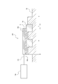
- FIG. 1A is a side view showing an example of the configuration of the strain measuring device 100.
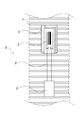
- FIG. 1B is a plan view showing an example of the configuration of the strain measuring device 100.
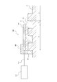
- FIG. 1C is a side view showing an example of the configuration of the strain measuring device 100.
- the strain measuring device 100 is a device that measures the strain of the FEP tube 10 having a bellows shape with an uneven surface.
- the strain measuring device 100 includes a viscous body 101, a strain gauge 102, an adhesive portion 103, a measuring instrument 104, and a lead wire 105.
- the viscous body 101 is provided so as to cover the unevenness of the FEP tube 10.
- the viscous body 101 is formed of, for example, a strain gauge protective coating material.
- strain gauge protective coating material for example, the following documents can be referred to. "Coating material for strain gauge protection: AK22", Spectris Co., Ltd. HBM, [online], [Searched on March 13, 2020], Internet ⁇ URL: https://www.hbm.com/jp/3079/ak22- tough-kneadable-putty />
- the viscosity of the viscous body 101 is preferably lower than that of the FEP tube 10 so as not to hinder the expansion and contraction of the FEP tube 10.
- the strain measuring device 100 measures the strain of the FEP pipe 10 buried in the ground
- the load of a vehicle or the like on the ground propagates while spreading to the ground, and the FEP pipe 10 propagates. Receives surface deflection of the ground.
- the rigidity of the viscous body 101 is lower than the rigidity of the FEP tube 10, so that the viscous body 101 is distorted following the deflection of the FEP tube 10. That is, the viscous body 101 can be deformed in a curved shape by following the deflection of the FEP tube 10.
- the material of the viscous body 101 is not particularly limited, but since it is in contact with the FEP tube 10 and the adhesive portion 103, the viscous body 101 is appropriately used in view of compatibility with the material used for the FEP tube 10 and the adhesive portion 103. It is preferable that the material is selected.
- the strain gauge 102 is, for example, a known strain gauge for plastics.
- the strain gauge 102 may have a known configuration as disclosed in Non-Patent Document 2, for example.
- the strain gauge 102 is adhered to the viscous body 101 via the adhesive portion 103, and is attached to a part of the surface S of the viscous body 101.
- the strain gauge 102 detects a change in the resistance value in the resistor and outputs the detection data to the measuring instrument 104 via the lead wire 105.
- the viscous body 101 can be deformed in a curved shape following the deflection of the FEP tube 10. Then, the strain gauge 102 attached to a part of the surface of the viscous body 101 can be deformed in a curved shape by following the deflection of the FEP tube 10 as in the viscous body 101. That is, since the strain gauge 102 can be deformed in a curved shape according to the deflection of the FEP tube 10, the strain measuring device 100 capable of accurately measuring the strain of the FEP tube 10 without underestimating is realized. can.
- the strain gauge 102 is provided with the viscous body 101 so that the region where the viscous body 101 covers the unevenness of the FEP tube 10 is wider than the region where the viscous body 101 and the strain gauge 102 adhere to each other.
- the strain of the viscous body 101 following the deflection of 10 can be detected with high accuracy.
- the adhesive portion 103 adheres the viscous body 101 and the strain gauge 102.
- the adhesive portion 103 may be, for example, a cyanoacrylate-based instant adhesive.
- the material of the adhesive portion 103 is not particularly limited, but since it is in contact with the viscous body 101, it is preferable that the material is appropriately selected in consideration of compatibility with the material used for the viscous body 101. ..
- the measuring instrument 104 is connected to the strain gauge 102 via a lead wire 105.
- the measuring instrument 104 measures the strain of the FEP tube 10 based on the detection data input from the strain gauge 102.
- the measuring instrument 104 may be connected not only to the strain gauge 102 by wire but also to the strain gauge 102 wirelessly.
- the measuring instrument 104 may have a function of storing detection data, measurement data, and the like.
- the measuring instrument 104 can also automatically measure the strain of the FEP tube 10 at a predetermined cycle.
- the components included in the strain measuring device 100 are not limited to the above-mentioned components.
- the strain measuring device 100 may further include, for example, a waterproof tape attached on the strain gauge 102, depending on the environment in which it is used. Thereby, the strain gauge 102 can be protected.
- the strain measuring device 100 may be further provided with a protective portion 106 which is provided at a boundary portion between the strain gauge 102 and the lead wire 105 and protects the lead wire 105.
- the protective portion 106 is formed of, for example, clay.
- the material of the protective portion 106 is not particularly limited, but it is preferable that the protective portion 106 is made of the same material as the viscous body 101.
- the strain measuring device 100 has a viscous body 101 having a lower rigidity than the FEP tube 10 and covering the unevenness of the FEP tube 10, and a strain gauge 102 attached to a part of the surface S of the viscous body 101. At least prepare. This makes it possible to accurately measure the strain of the FEP tube 10 without underestimating it.
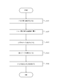
- step S101 the operator inserts the rod 11 into the FEP pipe 10 (see FIG. 3).
- the FEP tube 10 may not be in a straight state due to a curl or the like at the time of shipment from the factory. Therefore, the operator corrects the curl and the like of the FEP pipe 10 by inserting the rod 11 into the FEP pipe 10 and puts the FEP pipe 10 in a straight state.
- the operator may omit step S101 when the FEP pipe 10 is in a straight state.
- step S102 the operator provides the viscous body 101 on the FEP tube 10 at an arbitrary position where the strain is to be measured so as to cover the unevenness of the FEP tube 10.
- step S103 the operator attaches the strain gauge 102 to a part of the surface S of the viscous body 101 by using the adhesive portion 103.
- step S104 the operator attaches a waterproof tape on the strain gauge 102. If the operator determines that the waterproof tape is unnecessary, step S104 may be omitted.
- step S105 the operator measures the strain of the FEP tube 10 using the measuring instrument 104.
- the strain measuring method includes a step of covering the unevenness of the FEP tube 10 with a viscous body 101 having a rigidity lower than that of the FEP tube 10, and a step of attaching a strain gauge 102 to a part of the surface S of the viscous body 101. And at least include. This makes it possible to accurately measure the strain of the FEP tube 10 without underestimating it.
- the deformation of the viscous body 101 also becomes large following the deformation of the FEP tube 10, and a measurement error may occur due to the swelling or dent of the viscous body 101. be. Therefore, it is preferable that the operator performs the above-mentioned steps while paying sufficient attention to various conditions such as selection of materials for the viscous body 101 and the adhesive portion 103 in the measurement in which the deformation of the FEP tube 10 becomes large.
Landscapes
- Physics & Mathematics (AREA)
- General Physics & Mathematics (AREA)
- Chemical & Material Sciences (AREA)
- Analytical Chemistry (AREA)
- Engineering & Computer Science (AREA)
- Aviation & Aerospace Engineering (AREA)
- Measurement Of Length, Angles, Or The Like Using Electric Or Magnetic Means (AREA)
Abstract
ひずみ計測装置(100)は、FEP管(10)のひずみを計測するひずみ計測装置(100)であって、FEP管(10)より剛性が低く、FEP管(10)の凹凸を覆う粘性体(101)と、粘性体(101)の表面の一部に貼り付けられるひずみゲージ(102)と、を備える。
Description
本開示は、FEP(Flexible Electric Pipe)管のひずみを計測するひずみ計測装置およびひずみ計測方法に関する。
管は、建物、土木、農業分野などで広く使用されており、構造物への添え付け、地下への埋設という形態で設備として供用されている。近年は、低コスト無電柱化の推進によりFEP管の使用事例が増えてきている。FEP管は、軽量、偏平しにくい、可とう性を有するという優れた性能を有しており、無電柱化工事の経済化が期待されている(例えば、非特許文献1参照)。
管の品質管理又は設計の際の基礎的な物理量となるのが「ひずみ」である。従来は、管にひずみゲージを貼り付けて、その抵抗値の変化を検出し、管のひずみを計測していた(例えば、非特許文献2参照)。作業者は、計測された管のひずみに基づいて、管の曲がりなどを把握することができる。
「角形エフレックス」、古川電工HP、[online]、[2020年3月13日検索]、インターネット<URL:https://www.furukawa.co.jp/eflex/square/>
「パイプ歪計仕様書」、測商業技研、[online]、[2020年3月13日検索]、インターネット<URL: http://sokusho-giken.co.jp/download/files/spec/sensor/p-strain_spec.pdf>
FEP管は、その可とう性を活かし、曲げ状態で供用されるケースが存在する。その際に、地中における供用状態、例えば、地上における車両などの荷重で地盤がたわむことで、地中に埋設されているFEP管がたわむ問題、を把握する目的などで、FEP管のひずみ計測のニーズが存在する。
しかしながら、一般的な管は表面が平らであるため、ひずみゲージを表面に貼り付けることができるが、FEP管は表面が凹凸を有する蛇腹形状となっているため、ひずみゲージを表面に貼り付けることができない。このため、ひずみゲージを、FEP管の凸面に貼り付けて、FEP管のひずみを計測しようとすると、FEP管がたわんでもひずみゲージが曲線状に変形せず、FEP管のひずみが過小評価されるなど、計測エラーが生じてしまうという問題があった。
かかる事情に鑑みてなされた本開示の目的は、FEP管のひずみを過小評価することなく正確に計測することが可能なひずみ計測装置およびひずみ計測方法を提供することにある。
一実施形態に係るひずみ計測装置は、FEP管のひずみを計測するひずみ計測装置であって、前記FEP管より剛性が低く、前記FEP管の凹凸を覆う粘性体と、前記粘性体の表面の一部に貼り付けられるひずみゲージと、を備えることを特徴とする。
一実施形態に係るひずみ計測方法は、FEP管のひずみを計測するひずみ計測方法であって、前記FEP管の凹凸を、前記FEP管より剛性が低い粘性体で覆う被覆ステップと、前記粘性体の表面の一部に、ひずみゲージを貼り付ける貼付ステップと、を含むことを特徴とする。
本開示によれば、FEP管のひずみを過小評価することなく正確に計測することが可能なひずみ計測装置およびひずみ計測方法を提供することができる。
以下、本発明を実施するための形態について、図面を参照しながら説明する。
<ひずみ計測装置の構成>
図1A乃至図1Cを参照して、本実施形態に係るひずみ計測装置100の構成について説明する。図1Aは、ひずみ計測装置100の構成の一例を示す側面図である。図1Bは、ひずみ計測装置100の構成の一例を示す平面図である。図1Cは、ひずみ計測装置100の構成の一例を示す側面図である。
図1A乃至図1Cを参照して、本実施形態に係るひずみ計測装置100の構成について説明する。図1Aは、ひずみ計測装置100の構成の一例を示す側面図である。図1Bは、ひずみ計測装置100の構成の一例を示す平面図である。図1Cは、ひずみ計測装置100の構成の一例を示す側面図である。
ひずみ計測装置100は、表面が凹凸を有する蛇腹形状となっているFEP管10のひずみを計測する装置である。ひずみ計測装置100は、粘性体101と、ひずみゲージ102と、接着部103と、計測器104と、リード線105と、を備える。
粘性体101は、FEP管10の凹凸を覆うように設けられる。粘性体101は、例えば、ひずみゲージ保護用コーティング材で形成される。
ひずみゲージ保護用コーティング材の詳細については、例えば、下記の文献を参照することができる。
「ひずみゲージ保護用コーティング材:AK22」、スペクトリス株式会社HBM、[online]、[2020年3月13日検索]、インターネット<URL:https://www.hbm.com/jp/3079/ak22-tough-kneadable-putty/>
「ひずみゲージ保護用コーティング材:AK22」、スペクトリス株式会社HBM、[online]、[2020年3月13日検索]、インターネット<URL:https://www.hbm.com/jp/3079/ak22-tough-kneadable-putty/>
粘性体101は、FEP管10の伸縮を妨げないように、その剛性が、FEP管10より低いことが好ましい。例えば、ひずみ計測装置100が、地中に埋設されているFEP管10のひずみを計測することを前提とした場合、地上における車両などの荷重は、地盤に広がりながら伝搬して、FEP管10は地盤のたわみを面的に受ける。このような荷重の伝搬において、粘性体101の剛性がFEP管10の剛性より低いことで、粘性体101は、FEP管10のたわみに追従して、ひずむことになる。すなわち、粘性体101は、FEP管10のたわみに追従して、曲線状に変形することが可能となる。
粘性体101は、その材料が、特に限定されるものではないが、FEP管10および接着部103と接するため、FEP管10および接着部103に用いられる材料との相性を鑑みて、適宜、その材料が選定されることが好ましい。
ひずみゲージ102は、例えば、公知のプラスチック用ひずみゲージである。ひずみゲージ102は、例えば、非特許文献2に開示されているような公知の構成とすることができる。
ひずみゲージ102は、接着部103を介して粘性体101と接着し、粘性体101の表面Sの一部に貼り付けられる。ひずみゲージ102は、抵抗体における抵抗値の変化を検出し、検出データを、リード線105を介して計測器104へ出力する。
上述のように、粘性体101の剛性がFEP管10の剛性より低いことで、粘性体101は、FEP管10のたわみに追従して、曲線状に変形することが可能となる。そして、このような粘性体101の表面の一部に張り付けられたひずみゲージ102も、粘性体101と同様に、FEP管10のたわみに追従して、曲線状に変形することが可能となる。すなわち、FEP管10のたわみに合わせて、ひずみゲージ102を曲線状に変形させることができるため、FEP管10のひずみを過小評価することなく正確に計測することが可能なひずみ計測装置100を実現できる。
また、ひずみゲージ102が、粘性体101の表面Sの一部に貼り付けられることで、FEP管10、粘性体101、接着部103、および、ひずみゲージ102が重なった領域A、FEP管10および粘性体101が重なった領域B、および、FEP管10のみの領域C、の3領域が形成される(図1A参照)。すなわち、粘性体101がFEP管10の凹凸を覆う領域が、粘性体101とひずみゲージ102とが接着する領域より広くなるように、粘性体101が設けられることで、ひずみゲージ102は、FEP管10のたわみに追従する粘性体101のひずみを高精度に検出することができる。
接着部103は、粘性体101とひずみゲージ102とを接着する。接着部103は、例えば、シアノアクリレート系の瞬間接着剤などであってよい。接着部103は、その材料が、特に限定されるものではないが、粘性体101と接するため、粘性体101に用いられる材料との相性を鑑みて、適宜、その材料が選定されることが好ましい。
計測器104は、リード線105を介して、ひずみゲージ102と接続されている。計測器104は、ひずみゲージ102から入力された検出データに基づいて、FEP管10のひずみを計測する。計測器104は、ひずみゲージ102と有線で接続される構成のみならず、ひずみゲージ102と無線で接続される構成であってもよい。
計測器104は、検出データ、計測データなどを記憶する機能を有していてもよい。なお、計測器104は、所定の周期で、FEP管10のひずみを自動的に計測することも可能である。
ひずみ計測装置100が備える構成要素は、上述の構成要素に限定されるものではない。ひずみ計測装置100は、使用される環境に応じて、例えば、ひずみゲージ102の上に貼り付けられる防水テープをさらに備えていてもよい。これにより、ひずみゲージ102を保護することができる。
また、ひずみ計測装置100は、図1Cに示すように、ひずみゲージ102とリード線105との境界部に設けられ、リード線105を保護する保護部106をさらに備えていてもよい。保護部106は、例えば、粘土などで形成される。保護部106は、その材料が、特に限定されるものではないが、粘性体101と同じ材料で形成されることが好ましい。ひずみゲージ102とリード線105との境界部に、保護部106を設けることで、境界部におけるリード線105の折れ曲がりを抑制することができる。
本実施形態に係るひずみ計測装置100は、FEP管10より剛性が低く、FEP管10の凹凸を覆う粘性体101と、粘性体101の表面Sの一部に貼り付けられるひずみゲージ102と、を少なくとも備える。これにより、FEP管10のひずみを過小評価することなく正確に計測することが可能となる。
<ひずみ計測方法>
次に、図2および図3を参照して、本実施形態に係るひずみ計測方法について説明する。
次に、図2および図3を参照して、本実施形態に係るひずみ計測方法について説明する。
ステップS101において、作業者は、FEP管10に棒11を挿入する(図3参照)。FEP管10は、工場出荷時に巻き癖などがついて、真っ直ぐな状態となっていない場合がある。したがって、作業者は、FEP管10に棒11を挿入することで、FEP管10の巻き癖などを直し、FEP管10を真っ直ぐな状態とする。なお、作業者は、FEP管10が真っ直ぐな状態となっている場合には、ステップS101を省略してよい。
ステップS102において、作業者は、FEP管10において、ひずみを計測したい任意の箇所に、FEP管10の凹凸を覆うように、粘性体101を設ける。
ステップS103において、作業者は、粘性体101の表面Sの一部に、接着部103を用いて、ひずみゲージ102を貼り付ける。
ステップS104において、作業者は、ひずみゲージ102の上に、防水テープを貼り付ける。なお、作業者は、防水テープが不要であると判断する場合には、ステップS104を省略してよい。
ステップS105において、作業者は、計測器104を用いて、FEP管10のひずみを計測する。
本実施形態に係るひずみ計測方法は、FEP管10の凹凸を、FEP管10の剛性より低い粘性体101で覆うステップと、粘性体101の表面Sの一部に、ひずみゲージ102を貼り付けるステップと、を少なくとも含む。これにより、FEP管10のひずみを過小評価することなく正確に計測することが可能となる。
なお、FEP管10の変形が大きくなるような計測では、FEP管10の変形に追従して、粘性体101の変形も大きくなり、粘性体101の盛り上がり、くぼみなどにより、計測誤差が生じる場合がある。したがって、作業者は、FEP管10の変形が大きくなるような計測では、粘性体101および接着部103の材料選定など、各種条件に十分留意して上述のステップを実行することが好ましい。
上述の実施形態は代表的な例として説明したが、本開示の趣旨および範囲内で、多くの変更および置換ができることは当業者に明らかである。したがって、本発明は、上述の実施形態により制限するものと解するべきではなく、請求の範囲から逸脱することなく、種々の変形や変更が可能である。また、実施形態のフローチャートに記載の複数の工程を1つに組み合わせたり、あるいは1つの工程を分割したりすることが可能である。
10 FEP管
11 棒
20 壁面
100 ひずみ計測装置
101 粘性体
102 ひずみゲージ
103 接着部
104 計測器
105 リード線
106 保護部
11 棒
20 壁面
100 ひずみ計測装置
101 粘性体
102 ひずみゲージ
103 接着部
104 計測器
105 リード線
106 保護部
Claims (7)
- FEP管のひずみを計測するひずみ計測装置であって、
前記FEP管より剛性が低く、前記FEP管の凹凸を覆う粘性体と、
前記粘性体の表面の一部に貼り付けられるひずみゲージと、
を備える、ひずみ計測装置。 - 前記粘性体と前記ひずみゲージとを接着する接着部をさらに備える、
請求項1に記載のひずみ計測装置。 - 前記ひずみゲージの上に貼り付けられる防水テープをさらに備える、
請求項1又は2に記載のひずみ計測装置。 - 前記ひずみゲージとリード線との境界部に設けられる保護部をさらに備える、
請求項1から3のいずれか一項に記載のひずみ計測装置。 - FEP管のひずみを計測するひずみ計測方法であって、
前記FEP管の凹凸を、前記FEP管より剛性が低い粘性体で覆う被覆ステップと、
前記粘性体の表面の一部に、ひずみゲージを貼り付ける貼付ステップと、
を含む、ひずみ計測方法。 - 前記ひずみゲージの上に、防水テープを貼り付ける貼付ステップをさらに含む、
請求項5に記載のひずみ計測方法。 - 前記被覆ステップの前に、
前記FEP管に棒を挿入する挿入ステップをさらに含む、
請求項5又は6に記載のひずみ計測方法。
Priority Applications (3)
| Application Number | Priority Date | Filing Date | Title |
|---|---|---|---|
| JP2022507932A JP7321415B2 (ja) | 2020-03-18 | 2020-03-18 | ひずみ計測装置およびひずみ計測方法 |
| US17/912,099 US12216014B2 (en) | 2020-03-18 | 2020-03-18 | Deformation measuring device and deformation measuring method |
| PCT/JP2020/012105 WO2021186641A1 (ja) | 2020-03-18 | 2020-03-18 | ひずみ計測装置およびひずみ計測方法 |
Applications Claiming Priority (1)
| Application Number | Priority Date | Filing Date | Title |
|---|---|---|---|
| PCT/JP2020/012105 WO2021186641A1 (ja) | 2020-03-18 | 2020-03-18 | ひずみ計測装置およびひずみ計測方法 |
Publications (1)
| Publication Number | Publication Date |
|---|---|
| WO2021186641A1 true WO2021186641A1 (ja) | 2021-09-23 |
Family
ID=77771734
Family Applications (1)
| Application Number | Title | Priority Date | Filing Date |
|---|---|---|---|
| PCT/JP2020/012105 Ceased WO2021186641A1 (ja) | 2020-03-18 | 2020-03-18 | ひずみ計測装置およびひずみ計測方法 |
Country Status (3)
| Country | Link |
|---|---|
| US (1) | US12216014B2 (ja) |
| JP (1) | JP7321415B2 (ja) |
| WO (1) | WO2021186641A1 (ja) |
Citations (5)
| Publication number | Priority date | Publication date | Assignee | Title |
|---|---|---|---|---|
| JPH03191844A (ja) * | 1989-12-21 | 1991-08-21 | Sekisui Chem Co Ltd | 埋設管路の沈下挙動試験方法 |
| JPH04219901A (ja) * | 1990-12-19 | 1992-08-11 | Nippon Steel Corp | 保護膜を有する電気部品 |
| JPH0953752A (ja) * | 1995-08-11 | 1997-02-25 | Hitachi Cable Ltd | 波つき可とう管の布設工法 |
| JP2009209601A (ja) * | 2008-03-05 | 2009-09-17 | Nishimatsu Constr Co Ltd | 改良土のひずみ測定方法 |
| JP2009300096A (ja) * | 2008-06-10 | 2009-12-24 | Minebea Co Ltd | ひずみゲージ及びその製造方法並びにひずみゲージの取付方法 |
Family Cites Families (3)
| Publication number | Priority date | Publication date | Assignee | Title |
|---|---|---|---|---|
| KR20040000002A (ko) * | 2002-06-19 | 2004-01-03 | 엘지전자 주식회사 | 배관의 압력 측정장치 |
| JP5341855B2 (ja) * | 2010-10-01 | 2013-11-13 | 日本分光株式会社 | 微小容量圧力計 |
| CN106124142A (zh) * | 2016-08-08 | 2016-11-16 | 中国石油大学(华东) | 一种非金属柔性管刚度测量方法 |
-
2020
- 2020-03-18 JP JP2022507932A patent/JP7321415B2/ja active Active
- 2020-03-18 US US17/912,099 patent/US12216014B2/en active Active
- 2020-03-18 WO PCT/JP2020/012105 patent/WO2021186641A1/ja not_active Ceased
Patent Citations (5)
| Publication number | Priority date | Publication date | Assignee | Title |
|---|---|---|---|---|
| JPH03191844A (ja) * | 1989-12-21 | 1991-08-21 | Sekisui Chem Co Ltd | 埋設管路の沈下挙動試験方法 |
| JPH04219901A (ja) * | 1990-12-19 | 1992-08-11 | Nippon Steel Corp | 保護膜を有する電気部品 |
| JPH0953752A (ja) * | 1995-08-11 | 1997-02-25 | Hitachi Cable Ltd | 波つき可とう管の布設工法 |
| JP2009209601A (ja) * | 2008-03-05 | 2009-09-17 | Nishimatsu Constr Co Ltd | 改良土のひずみ測定方法 |
| JP2009300096A (ja) * | 2008-06-10 | 2009-12-24 | Minebea Co Ltd | ひずみゲージ及びその製造方法並びにひずみゲージの取付方法 |
Also Published As
| Publication number | Publication date |
|---|---|
| US12216014B2 (en) | 2025-02-04 |
| US20230041474A1 (en) | 2023-02-09 |
| JP7321415B2 (ja) | 2023-08-07 |
| JPWO2021186641A1 (ja) | 2021-09-23 |
Similar Documents
| Publication | Publication Date | Title |
|---|---|---|
| Danisch et al. | Spatially continuous six degree of freedom position and orientation sensor | |
| KR101531890B1 (ko) | 변위계 어셈블리 | |
| US10288455B2 (en) | Methods of deploying fibre optics via a coilable member for sensing or communications applications | |
| US20150165684A1 (en) | Systems and methods for providing coupling joints | |
| CN210005752U (zh) | 一种定点式光缆 | |
| JP7321415B2 (ja) | ひずみ計測装置およびひずみ計測方法 | |
| JP2009020016A (ja) | 光ファイバセンサケーブル | |
| CN106441376A (zh) | 石墨栅柔性电阻应变片及其制造方法 | |
| JP5707617B2 (ja) | 歪検出用光ファイバコード | |
| US20230236381A1 (en) | Methods and apparatus for remotely laying cable | |
| JP2002267425A (ja) | 歪み検知装置および歪み検知用複合ケーブル | |
| CN108007432B (zh) | 地下管线的地表监测装置及其使用方法 | |
| US20170138829A1 (en) | Method for determining elastic properties of a motor vehicle cable harness | |
| US9061425B2 (en) | Frame transfer device for an optical strain gauge structure | |
| CN109751958A (zh) | 一种管型母线轨迹测量方法 | |
| JP2001174341A (ja) | 圧力分布センサ | |
| CN110031138B (zh) | 基于光纤光栅技术的土工格栅受力的直接测量方法 | |
| Yu et al. | Stress and strain monitoring at Tottenham court road station, London, UK | |
| KR100833718B1 (ko) | 판형 계측 센서를 이용한 파일 연결부의 변형 측정 장치 | |
| JPH11173943A (ja) | 歪み分布測定システム | |
| JP2003279424A (ja) | 環状弾性体 | |
| JP2009192250A (ja) | 光ファイバセンサケーブル | |
| CN219829965U (zh) | 基于分布式光纤的盾构管片变形、渗漏在线监测装置 | |
| JPS63241409A (ja) | 曲がり検出センサ− | |
| JP2002267424A (ja) | 歪み検知装置および歪み検知用複合ケーブル |
Legal Events
| Date | Code | Title | Description |
|---|---|---|---|
| 121 | Ep: the epo has been informed by wipo that ep was designated in this application |
Ref document number: 20925947 Country of ref document: EP Kind code of ref document: A1 |
|
| ENP | Entry into the national phase |
Ref document number: 2022507932 Country of ref document: JP Kind code of ref document: A |
|
| NENP | Non-entry into the national phase |
Ref country code: DE |
|
| 122 | Ep: pct application non-entry in european phase |
Ref document number: 20925947 Country of ref document: EP Kind code of ref document: A1 |