WO2021186639A1 - Uボルト取り付け治具、およびuボルト取り付け方法 - Google Patents
Uボルト取り付け治具、およびuボルト取り付け方法 Download PDFInfo
- Publication number
- WO2021186639A1 WO2021186639A1 PCT/JP2020/012103 JP2020012103W WO2021186639A1 WO 2021186639 A1 WO2021186639 A1 WO 2021186639A1 JP 2020012103 W JP2020012103 W JP 2020012103W WO 2021186639 A1 WO2021186639 A1 WO 2021186639A1
- Authority
- WO
- WIPO (PCT)
- Prior art keywords
- bolt
- fixing
- joining
- fixing member
- hole
- Prior art date
- Legal status (The legal status is an assumption and is not a legal conclusion. Google has not performed a legal analysis and makes no representation as to the accuracy of the status listed.)
- Ceased
Links
Images









Classifications
-
- F—MECHANICAL ENGINEERING; LIGHTING; HEATING; WEAPONS; BLASTING
- F16—ENGINEERING ELEMENTS AND UNITS; GENERAL MEASURES FOR PRODUCING AND MAINTAINING EFFECTIVE FUNCTIONING OF MACHINES OR INSTALLATIONS; THERMAL INSULATION IN GENERAL
- F16L—PIPES; JOINTS OR FITTINGS FOR PIPES; SUPPORTS FOR PIPES, CABLES OR PROTECTIVE TUBING; MEANS FOR THERMAL INSULATION IN GENERAL
- F16L3/00—Supports for pipes, cables or protective tubing, e.g. hangers, holders, clamps, cleats, clips, brackets
- F16L3/02—Supports for pipes, cables or protective tubing, e.g. hangers, holders, clamps, cleats, clips, brackets partly surrounding the pipes, cables or protective tubing
- F16L3/04—Supports for pipes, cables or protective tubing, e.g. hangers, holders, clamps, cleats, clips, brackets partly surrounding the pipes, cables or protective tubing and pressing it against a wall or other support
-
- B—PERFORMING OPERATIONS; TRANSPORTING
- B25—HAND TOOLS; PORTABLE POWER-DRIVEN TOOLS; MANIPULATORS
- B25B—TOOLS OR BENCH DEVICES NOT OTHERWISE PROVIDED FOR, FOR FASTENING, CONNECTING, DISENGAGING, OR HOLDING
- B25B11/00—Work holders not covered by any preceding group in the subclass, e.g. magnetic work holders, vacuum work holders
- B25B11/02—Assembly jigs
Definitions
- This disclosure relates to a U-bolt mounting jig and a U-bolt mounting method.
- Patent Document 1 includes a U-bolt for fixing a pipe to a frame, a first support portion for supporting the pipe, and a saddle including a second support portion arranged between the pipe and the frame.
- a U-bolt structure that improves support rigidity and load capacity and allows fine adjustment of the saddle is disclosed.
- the bolt hole into which the U bolt is inserted is formed so as to be larger than the diameter of the U bolt.
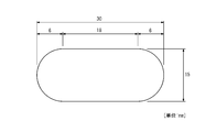
- a U-bolt having a diameter of 9 mm as shown in FIG. 6B is inserted into a bolt hole having a length of 30 mm in the longitudinal direction and a length of 15 mm in the lateral direction as shown in FIG. 6A.
- An extra space of 10.5 mm is formed at both ends of the U bolt in the longitudinal direction, and 3 mm is formed at both ends of the U bolt in the lateral direction.
- An object of the present disclosure made in view of such circumstances is to provide a U-bolt mounting jig capable of mounting U-bolts perpendicularly to a member without increasing the number of parts, and a U-bolt mounting method. be.
- the U-bolt mounting jig is a U-bolt mounting jig for mounting a U-bolt for fixing a pipeline to a member, and is spaced at a predetermined interval so as to be perpendicular to the member.
- the first fixing member and the second fixing member provided so as to face each other and in contact with the side portion of the U bolt, and the first fixing member and the second fixing member so as to be parallel to the member.
- the telescopic member that is fitted and provided so as to be in contact with the central portion of the U bolt is joined to the first fixing member and the second fixing member, and the first fixing member and the second fixing member are sandwiched between the above-mentioned predetermined. It is characterized by including a first joining member and a second joining member for finely adjusting the interval between the two.
- the U-bolt attachment method is a U-bolt attachment method for attaching a U-bolt for fixing a pipeline to a member, and the first fixing member and the second fixing member are perpendicular to the member.
- the step of fixing the first fixing member and the second fixing member to the member at a predetermined interval, and the side portion of the U bolt come into contact with the first fixing member and the second fixing member.
- the U-bolt is perpendicular to the member
- the side portion of the U-bolt is arranged closer to the member than the central portion of the U-bolt and a straight line connecting both ends of the U-bolt. Is meant to be parallel to the surface of the member.
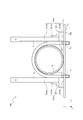
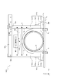
- FIG. 1A is a side view showing an example of the configuration of the U-bolt mounting jig 100.
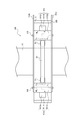
- FIG. 1B is a plan view showing an example of the configuration of the U-bolt mounting jig 100.
- the telescopic member 102 shown in FIG. 1A is omitted.
- the U-bolt attachment jig 100 is a jig for attaching the U-bolt 20 for fixing the pipeline 10 to the attachment member 300 attached to the structure.
- ⁇ member 300 is the surface S 1 is a plane, the conduit 10 may have a stable and capable of supporting a configuration.
- the supporting member 300 is made of, for example, L-shaped steel, flat steel, H-shaped steel, or the like.
- the attachment member 300 is provided with a bolt hole H 1 into which one end of the U bolt 20 is inserted and a bolt hole H 2 into which the other end of the U bolt 20 is inserted.
- the pipeline 10 is a resin or metal pipe, for example, a hard vinyl pipe, an FRP (Fiber Reinforced Plastics) pipe, a steel pipe, a FRPM (Fiberglass Reinforced Plastic Mortar) pipe, or the like.
- the pipeline 10 may have a cylindrical shape, and its configuration is not particularly limited.
- the pipeline 10 may be provided with a joint or the like and may have irregularities on the outside.
- the conduit 10 may be externally provided with a protective piece 11 bonded with an adhesive (see FIG. 1A).
- the conduit 10 When the conduit 10 is provided with the protective piece 11, the conduit 10 can be protected when the conduit 10 is fixed to the mounting member 300 by the U bolt 20.
- FIG. 1 a case where one pipeline 10 is installed on the auxiliary member 300 is taken as an example, but the number of pipelines 10 installed on the auxiliary member 300 is not particularly limited.
- the U-bolt 20 is a single steel material having a curved central portion, a linear shape at the side portions, and a bolt structure at both ends. Both ends of the U bolt 20 are inserted into the bolt holes H 1 and the bolt holes H 2 and screwed into the nut via the conduit 10, the mounting member 300, and the washer. As a result, the pipeline 10 is fixed to the attachment member 300.
- the U-bolt mounting jig 100 includes a fixing member (first fixing member) 101a, a fixing member (second fixing member) 101b, an expansion / contraction member 102, a joining member (first joining member) 103a, and a joining member (second joining).
- a member) 103b, a stop member (first stop member) 104, and a stop member (second stop member) 105 are provided.
- the fixing member 101a includes a fixing portion 1011a, a branch line portion 1012a, and a reinforcing portion 1013a.
- the fixing member 101b includes a fixing portion 1011b, a branch line portion 1012b, and a reinforcing portion 1013b.
- the fixing members 101a and 101b are fixed to the mounting member 300 at intervals L so as to be perpendicular to the mounting member 300.
- the fixing members 101a and 101b have slide grooves Ca and Cb, and are provided so that the slide grooves Ca and Cb are in contact with the side portion of the U bolt 20.
- the interval L is not particularly limited, and is appropriately adjusted by the operator based on, for example, the nominal size of the U bolt 20.
- the side portion of the U bolt 20 is drawn so as to be in contact with the end portions of the fixing members 101a and 101b, but the side portion of the U bolt 20 may be fitted in the slide grooves Ca and Cb.
- the fixing portions 1011a and 1011b are provided with magnets 1014a and 1014b embedded therein.
- the fixing portions 1011a and 1011b can be firmly fixed to the mounting member 300.
- the operator does not have to perform work such as pressing the fixed portions 1011a and 1011b by hand, so that it is possible to avoid the inconvenience that both hands are blocked and the work is difficult.
- the branch line portions 1012a and 1012b are joined to the fixing portions 1011a and 1011b.
- the joining method for joining the branch line portions 1012a and 1012b and the fixing portions 1011a and 1011b is not particularly limited, and for example, they are joined by a known method such as bolt joining, welding joining, and adhesive joining.
- the branch line portion 1012a is provided with a through hole K (see FIG. 1B).
- the branch line portion 1012a is joined to the joining member 103a and the joining member 103b via the stopping member 104 inserted into the through hole K.
- the branch line portion 1012b is provided with a through hole O (see FIG. 1B).
- the branch line portion 1012a is joined to the joining member 103a and the joining member 103b via the stopping member 105 inserted into the through hole O.
- the reinforcing portion 1013a is joined to the fixed portion 1011a and the branch line portion 1012a to reinforce the fixed portion 1011a and the branch line portion 1012a.
- the reinforcing portion 1013b is joined to the fixed portion 1011b and the branch line portion 1012b to reinforce the fixed portion 1011b and the branch line portion 1012b.
- the reinforcing portions 1013a and 1013b have an L-shape, and one side thereof is joined to the fixed portions 1011a and 1011b, and the other side is joined to the branch line portions 1012a and 1012b.
- the joining method in which the reinforcing portion 1013a, the fixing portion 1011a, and the branch line portion 1012a are joined, and the joining method in which the reinforcing portion 1013b, the fixing portion 1011b, and the branch line portion 1012b are joined are not particularly limited, and for example. , Bolt joining, welding joining, adhesive joining, etc., are joined by known methods.
- One end of the telescopic member 102 is fitted into the slide groove Ca provided in the fixing member 101a, and the other end is fitted in the slide groove Cb provided in the fixing member 101b so as to be parallel to the mounting member 300.
- the telescopic member 102 is provided so as to be in contact with the central portion of the U bolt 20.
- the telescopic member 102 can move forward and backward along the slide groove Ca and the slide groove Cb in the Z-axis direction.
- the upper portion of the U bolt 20 can be fixed to the U bolt mounting jig 100 so that the U bolt 20 is perpendicular to the mounting member 300 according to the size (height) of the U bolt 20. ..
- the telescopic member 102 can be expanded and contracted in the X-axis direction according to the distance L between the fixing member 101a and the fixing member 101b.
- the telescopic member 102 is a telescopic pole used in, for example, an antenna.
- the telescopic pole includes a plurality of cylindrical pole members, and each pole member is slidably fitted along the central axis of the cylinder.
- the structure of the telescopic member 102 is not particularly limited.
- the telescopic member 102 preferably has a groove along a curved shape in the central portion of the U bolt 20 at a position in contact with the central portion of the U bolt 20.
- the U bolt 20 can stably maintain a state perpendicular to the mounting member 300. That is, it is possible to prevent the U bolt 20 from being slanted with respect to the mounting member 300.
- the telescopic member 102 preferably includes a magnet 1021 embedded therein. Since the telescopic member 102 includes the magnet 1021, the telescopic member 102 can be firmly fixed to the U-bolt 20, so that the U-bolt 20 can stably maintain a state perpendicular to the mounting member 300. Can be done. That is, it is possible to prevent the U bolt 20 from being slanted with respect to the mounting member 300.
- the joining members 103a and 103b are joined to the fixing members 101a and 101b, and the distance L between the fixing member 101a and the fixing member 101b is finely adjusted.
- the joining members 103a and 103b are, for example, metal fittings.
- the joining member 103a is provided with a plurality of through holes J n (n ⁇ 2) (see FIG. 3F). More specifically, one end of the joint member 103a, the through-holes J 1 is provided on the other end of the joint member 103a, the through-holes J 2 ⁇ J n are provided. The through-holes J 1 is stop member 104 is inserted. A stop member 105 is inserted into the through holes J 2 to J n.
- the joining member 103a is fixed to the fixing member 101a via the stop member 104 inserted into the through hole J 1 and the through hole K, and the stop member 105 inserted into the through holes J 2 to J n and the through hole O. Join with member 101b.
- the joining member 103b is provided with a plurality of through holes M n (n ⁇ 2) (see FIG. 3F). More specifically, one end of the joint member 103b, the through-hole M 1 is provided on the other end of the joint member 103b, the through-hole M 2 ⁇ M n are provided. The through-hole M 1 is stop member 104 is inserted. A stop member 105 is inserted into the through holes M 2 to M n. The joining member 103b is fixed to the fixing member 101a via the stop member 104 inserted into the through hole M 1 and the through hole K, and the stop member 105 inserted into the through holes M 2 to M n and the through hole O. Join with member 101b.
- the plurality of through holes J n and the plurality of through holes M n are provided corresponding to the nominal dimensions of the U bolt 20.
- each through hole is provided so that the distance L between the fixing member 101a and the fixing member 101b matches the size (width) of the U bolt of "65 (M8)".
- the stop member 104 is inserted into the through hole J 1 , the through hole K, and the through hole M 1, and the stop member 105 is inserted into the through hole J 2 , the through hole O, and the through hole M 2.
- the distance L between the fixing member 101b and the fixing member 101b is accurately adjusted according to the width of the U bolt of "65 (M8)".
- each through hole is provided so that the distance L between the fixing member 101a and the fixing member 101b matches the size (width) of the U bolt of "100 (M10)".
- the stop member 104 is inserted into the through hole J 1 , the through hole K, and the through hole M 1, and the stop member 105 is inserted into the through hole J 5 , the through hole O, and the through hole M 5 , so that the fixing member 101a is inserted.
- the distance L between the fixing member 101b and the fixing member 101b is accurately adjusted according to the width of the U bolt of "100 (M10)".
- the joining members 103a and 103b are described with scales corresponding to the nominal dimensions of the U bolt 20.
- a scale “65 (M8)” is described in the vicinity of the through hole J 2 in the joining member 103a and in the vicinity of the through hole M 2 in the joining member 103b.
- a scale "100 (M10)” is described in the vicinity of the through hole J 5 in the joining member 103a and in the vicinity of the through hole M 5 in the joining member 103b.
- the number and positions of through holes provided in the joining members 103a and 103b, or the positions of the scales described in the joining members 103a and 103b can be appropriately changed according to the size of the U bolt 20, and are particularly limited. It's not something.
- the stopping member 104 is a member that is inserted into the through hole J 1 , the through hole K, and the through hole M 1 to join the fixing member 101a and the joining members 103a and 103b.
- the stopping member 104 is, for example, a metal fitting.
- the stopping member 105 is a member that is inserted into the through holes J 2 to J n , the through holes O, and the through holes M 2 to M n to join the fixing member 101b and the joining members 103a and 103b.
- the stopper 105 is, for example, a metal fitting.
- the stop member 104 is inserted into the through hole J 1 , the through hole K, and the through hole M 1 , and the stop member 105 is a through hole. It is inserted into J 2 , the through hole O, and the through hole M 2.
- the stop member 104 is inserted into the through hole J 1 , the through hole K, and the through hole M 1 , and the stop member 105 is a through hole. J 5 , through hole O, and through hole M 5 are inserted.
- the stopping member 104 is not pulled out after being once inserted into the through hole J 1 , the through hole K, and the through hole M 1 by the operator.
- the stopping member 105 may be inserted into the through holes J 2 to J n , the through holes O, and the through holes M 2 to M n by the operator, or the through holes J 2 to J n , the through holes O, And, it is preferable that it is extracted from the through holes M 2 to M n.
- the stop member 104 is fixed to the through hole J 1 , the through hole K, and the through hole M 1
- the stop member 105 is fixed to the through hole J 2 to J n , the through hole O, and the through hole M by the operator.
- junction members 103a, 103b as a fulcrum stop member 104, it is possible to rotate (see arrows in FIG. 1A). That is, the operator can remove the joining members 103a and 103b from the fixing member 101b and attach the joining members 103a and 103b to the fixing member 101b. As a result, the operator can appropriately remove the joining members 103a and 103b from the fixing member 101b and change the distance L between the fixing member 101a and the fixing member 101b according to the size of the U bolt 20.
- the U-bolt mounting jig 100 is fixed to the mounting member 300 at intervals L so as to be perpendicular to the mounting member 300, and is provided so as to be in contact with the side portion of the U-bolt 20.
- the telescopic members 102 which are fitted to the fixing members 101a and 101b so as to be parallel to the members 101a and 101b and the attachment member 300 and are provided so as to be in contact with the central portion of the U bolt, are joined to the fixing members 101a and 101b.
- the joining members 103a and 103b for finely adjusting the interval L are provided. This makes it possible to attach the U bolt 20 perpendicularly to the mounting member 300 without increasing the number of parts.
- the U-bolt mounting jig 100 has high accuracy in determining the distance between the fixing member 101a and the fixing member 101b and the distance between the mounting member 300 and the telescopic member 102 according to the size of the U-bolt. Can be adjusted to. As a result, any kind of U-bolt can be attached vertically to the mounting member 300, so that the operator can install the U-bolt without worrying about the size of the U-bolt. It can be carried out.
- step S101 as shown in FIG. 3A, the operator attaches the fixing members 101a and 101b to the attachment member 300 at intervals L so that the fixing members 101a and 101b are perpendicular to the attachment member 300. Fix it.
- step S102 the operator provides the U-bolt 20 on the auxiliary member 300 so that the side portion of the U-bolt 20 is in contact with the fixing members 101a and 101b.
- one of the side portions of the U bolt 20 may be fitted into the slide groove Ca provided in the fixing member 101a, and the other side portion of the U bolt 20 may be fitted into the slide groove Cb provided in the fixing member 101b. preferable.
- step S103 the operator fits one end of the telescopic member 102 into the slide groove Ca provided in the fixing member 101a so that the telescopic member 102 is parallel to the mounting member 300.
- the other end of the telescopic member 102 is fitted into the slide groove Cb provided in the fixing member 101b.
- the length of the telescopic member 102 is adjusted according to the distance L between the fixing member 102a and the fixing member 102b.
- step S104 the operator slides the telescopic member 102 in the direction of the arrow so that the telescopic member 102 comes into contact with the upper part of the U bolt 20. Since one end of the telescopic member 102 is fitted in the slide groove Ca provided in the fixing member 101a and the other end is fitted in the slide groove Cb provided in the fixing member 101b, the telescopic member 102 is fitted along the slide groove Ca and the slide groove Cb. You can move forward and backward smoothly in the direction of the arrow.
- step S105 the operator inserts the stopping member 104 into the through hole J 1 , the through hole K, and the through hole M 1, and inserts the fixing member 101a and the joining members 103a, 103b.
- the operator inserts the stopping member 105 into the through holes J 2 to J n , the through holes O, and the through holes M 2 to M n to join the fixing member 101b and the joining members 103a and 103b. ..
- the nominal size of the U bolt 20 is "100 (M10)"
- the operator inserts the stop member 104 into the through hole J 1 , the through hole K, and the through hole M 1 , and the stop member 105. Is inserted into the through hole J 5 , the through hole O, and the through hole M 5.
- step S106 as shown in FIG. 3E, the operator, from the surface S 1 and the opposite surface S 2 of ⁇ member 300, via a washer 21a, fastening a nut 22a on one end of the U-bolt 20. Further, the operator, from the surface S 1 and the opposite surface S 2 of ⁇ member 300, via the washer 21b, fastening a nut 22b to the other end of the U-bolt 20. As a result, the pipeline 10 is fixed to the attachment member 300.
- step S101 to step S106 the operator can attach the U bolt 20 perpendicularly to the mounting member 300 without increasing the number of parts.
- step S107 the operator pulls out the stop member 105 from the through holes J 2 to J n , the through holes O, and the through holes M 2 to M n .
- the joining members 103a and 103b are removed from the fixing member 101b.
- the nominal dimension of the U bolt 20 is "100 (M10)"
- the operator pulls out the stop member 105 from the through hole J 5 , the through hole O, and the through hole M 5 .
- step S108 as shown in FIG. 3G, the operator removes the fixing member 101a, the fixing member 101b, and the telescopic member 102 to be joined to the joining members 103a and 103b from the mounting member 300.
- the U-bolt mounting method according to the present embodiment includes the above-mentioned steps S101 to S108. This makes it possible to attach the U bolt 20 perpendicularly to the mounting member 300 without increasing the number of parts.
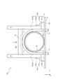
- the U-bolt mounting jig 100A according to the first modification is different from the U-bolt mounting jig 100 according to the present embodiment because the U-bolt mounting jig 100 according to the present embodiment does not have a spirit level and is a fixing member. While the scales are not described on the 101a and 101b and the telescopic member 102, the U-bolt mounting jig 100A according to the first modification is provided with a spirit level, and the scales are described on the fixing members 101a and 101b and the telescopic member 102. It is a point that has been done. Since the other configurations are the same as those of the U-bolt mounting jig 100 according to the present embodiment, duplicate description will be omitted.
- the fixing members 101a and 101b have a scale ⁇ for maintaining the telescopic member 102 horizontally with respect to the mounting member 300.
- the telescopic member 102 can stably maintain a horizontal state with respect to the mounting member 300.
- the telescopic member 102 has a scale ⁇ for maintaining the U-bolt 20 perpendicular to the mounting member 300.
- the U bolt 20 can stably maintain a state perpendicular to the mounting member 300.
- the level 400 is placed on the telescopic member 102 and detects the inclination of the U bolt 20 with respect to the mounting member 300. While visually observing the level 400, the operator finely adjusts the position of the telescopic member 102 so that the telescopic member 102 is in a horizontal state with respect to the mounting member 300. Thereby, the mounting accuracy of the U bolt 20 can be further improved.
- the U-bolt mounting jig 100A according to the first modification can mount the U-bolt 20 perpendicularly to the mounting member 300 without increasing the number of parts.
- the U-bolt mounting jig 100B according to the second modification is different from the U-bolt mounting jig 100A according to the first modification, whereas the U-bolt mounting jig 100A according to the first modification does not have a handle.
- the U-bolt mounting jig 100B according to the second modification is provided with a handle. Since the other configurations are the same as those of the U-bolt mounting jig 100A according to the first modification, duplicate description will be omitted.
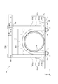
- the handle 500 is attached to the fixing members 101a and 101b.
- the handle 500 includes fastening portions 500a and 500b.
- the fixing members 101a and 101b include the parts to be fastened 501a and 501b.
- the handles 500 are attached to the fixing members 101a and 101b by joining the fastening portions 500a and 500b provided on the handle 500 and the fastened portions 501a and 501b provided on the fixing members 101a and 101b.
- the handle 500 can rotate around the joint portion where the fastening portions 500a and 500b and the fastened portions 501a and 501b are joined as a fulcrum.
- the fastening portions 500a and 500b may be, for example, a hook or a magnet, but the configuration thereof is not particularly limited.
- the fastened portions 501a and 501b may be, for example, hook stoppers and magnets, but the configuration thereof is not particularly limited.
- the handle 500 preferably has a shape that is easy for the operator to grasp by hand, and is composed of, for example, a rod-shaped member.
- the U-bolt mounting jig 100B according to the second modification can mount the U-bolt 20 perpendicularly to the mounting member 300 without increasing the number of parts.
Landscapes
- Engineering & Computer Science (AREA)
- General Engineering & Computer Science (AREA)
- Mechanical Engineering (AREA)
- Supports For Pipes And Cables (AREA)
- Connection Of Plates (AREA)
- Bridges Or Land Bridges (AREA)
Abstract
Uボルト取り付け治具(100)は、添架部材(300)に対して垂直となるように、所定の間隔を空けて対向し、Uボルト(20)の側部と接するように設けられる第1固定部材(101a)および第2固定部材(101b)と、添架部材(300)に対して平行となるように、第1固定部材(101a)および第2固定部材(101b)に嵌められ、Uボルト(20)の中央部と接するように設けられる伸縮部材(102)と、第1固定部材(101a)および第2固定部材(101b)と接合し、第1固定部材(101a)および第2固定部材(101b)を挟んで所定の間隔を微調整する第1接合部材(103a)および第2接合部材(103b)と、を備える。
Description
本開示は、Uボルト取り付け治具、およびUボルト取り付け方法に関する。
従来、橋梁などの構造物に添架された添架部材に、管路を固定するため、Uボルトを用いることが知られている。例えば、特許文献1には、配管を架構に固定するためのUボルトと、配管を支持する第1支持部および配管と架構との間に配置される第2支持部を含むサドルと、を備えることで、支持剛性および耐荷重を向上させ且つサドルの微調整が可能なUボルト構造が開示されている。
Uボルトが挿入されるボルト孔は、Uボルトの直径より大きくなるように形成される。例えば、図6Aに示すような、長手方向の長さが30mm、短手方向の長さが15mmのボルト孔に、例えば、図6Bに示すような、直径9mmのUボルトが挿入されると、長手方向においてUボルトの両端には10.5mm、短手方向においてUボルトの両端には3mmの余剰スペースが形成される。
作業者は、Uボルトにナットを締結する際、通常、片方ずつナットを締めていく。このため、ボルト孔に余剰スペースが形成されていると、図7に示すように、Uボルト20Aが部材300Aに対して斜めに取り付けられてしまうという問題があった。また、特許文献1に記載のUボルト構造は、部品点数が多いため、コストおよび取り付け稼働が増大し、メンテナンスが困難であるという問題もある。
かかる事情に鑑みてなされた本開示の目的は、部品点数を増やさずに、Uボルトを部材に対して垂直に取り付けることが可能なUボルト取り付け治具、およびUボルト取り付け方法を提供することにある。
一実施形態に係るUボルト取り付け治具は、管路を部材に固定するためのUボルトを取り付けるUボルト取り付け治具であって、前記部材に対して垂直となるように、所定の間隔を空けて対向し、前記Uボルトの側部と接するように設けられる第1固定部材および第2固定部材と、前記部材に対して平行となるように、前記第1固定部材および前記第2固定部材に嵌められ、前記Uボルトの中央部と接するように設けられる伸縮部材と、前記第1固定部材および前記第2固定部材と接合し、前記第1固定部材および前記第2固定部材を挟んで前記所定の間隔を微調整する第1接合部材および第2接合部材と、を備えることを特徴とする。
一実施形態に係るUボルト取り付け方法は、管路を部材に固定するためのUボルトを取り付けるUボルト取り付け方法であって、第1固定部材および第2固定部材が前記部材に対して垂直となるように、前記第1固定部材および前記第2固定部材を、所定の間隔を空けて前記部材に固定するステップと、前記Uボルトの側部が前記第1固定部材および前記第2固定部材と接するように、前記部材に前記Uボルトを設けるステップと、伸縮部材が前記部材に対して平行となるように、前記伸縮部材を前記第1固定部材および前記第2固定部材に嵌めるステップと、前記伸縮部材が前記Uボルトの中央部と接するように、前記伸縮部材をスライドさせるステップと、前記第1固定部材および前記第2固定部材に、第1接合部材および第2接合部材を接合し、前記所定の間隔を微調整するステップと、前記Uボルトにナットを締結するステップと、前記第1接合部材および前記第2接合部材を、前記第2固定部材から取り外すステップと、前記第1接合部材および前記第2接合部材と接合する前記第1固定部材、前記第2固定部材、ならびに前記伸縮部材を、前記部材から取り外すステップと、を含むことを特徴とする。
本開示によれば、部品点数を増やさずに、Uボルトを部材に対して垂直に取り付けることが可能なUボルト取り付け治具、およびUボルト取り付け方法を提供することができる。
以下、本発明を実施するための形態について、図面を参照しながら説明する。
本明細書において、「Uボルトが部材に対して垂直である」とは、Uボルトの側部がUボルトの中央部より部材に近い側に配置され、且つ、Uボルトの両端部を結ぶ直線が部材の表面に対して平行であることを意味するものとする。また、「Uボルトが部材に対して斜めである」とは、Uボルトの両端部を結ぶ直線が部材の表面に対して傾いていることを意味するものとする。
また、本明細書において、「上」、「下」、「垂直」とは、図面に描かれた座標軸表示のZ軸に平行な方向を意味するものとし、「平行」とは、図面に描かれた座標軸表示のXY平面に平行な方向を意味するものとする。
<Uボルト取り付け治具の構成>
図1Aおよび図1Bを参照して、本実施形態に係るUボルト取り付け治具100の構成について説明する。図1Aは、Uボルト取り付け治具100の構成の一例を示す側面図である。図1Bは、Uボルト取り付け治具100の構成の一例を示す平面図である。なお、図1Bにおいて、図1Aに示されている伸縮部材102は省略されている。
図1Aおよび図1Bを参照して、本実施形態に係るUボルト取り付け治具100の構成について説明する。図1Aは、Uボルト取り付け治具100の構成の一例を示す側面図である。図1Bは、Uボルト取り付け治具100の構成の一例を示す平面図である。なお、図1Bにおいて、図1Aに示されている伸縮部材102は省略されている。
Uボルト取り付け治具100は、構造物に添架された添架部材300に、管路10を固定するためのUボルト20を取り付ける治具である。
添架部材300は、表面S1が平面であり、管路10を安定して支持可能な構成を有していればよい。添架部材300は、例えば、L形鋼、平鋼、H形鋼などで形成される。添架部材300には、Uボルト20の一端が挿入されるボルト孔H1およびUボルト20の他端が挿入されるボルト孔H2が設けられている。
管路10は、樹脂製又は金属製の管であり、例えば、硬質ビニル管、FRP(Fiber Reinforced Plastics)管、鋼管、FRPM(Fiberglass Reinforced Plastic Mortar)管などである。管路10は、円筒形状を有していればよく、その構成が特に限定されるものではない。例えば、管路10は、継ぎ手などが設けられて、外部に凹凸を有していてもよい。例えば、管路10は、接着剤により接着された保護片11を外部に備えていてもよい(図1A参照)。管路10が保護片11を備えることで、管路10がUボルト20により添架部材300に固定される際に、管路10を保護することが可能となる。なお、図1では、添架部材300に管路10が1本設置される場合を一例に挙げているが、添架部材300に設置される管路10の個数は、特に限定されるものではない。
Uボルト20は、中央部が湾曲した形状を有し、側部が直線形状を有し、両端部がボルト構造となっている1本の鋼材である。Uボルト20は、両端部が、ボルト孔H1およびボルト孔H2に挿入されて、管路10、添架部材300、および座金を介して、ナットと螺合する。これにより、管路10は添架部材300に固定される。
以下、Uボルト取り付け治具100について、詳細に説明する。
Uボルト取り付け治具100は、固定部材(第1固定部材)101a,固定部材(第2固定部材)101bと、伸縮部材102と、接合部材(第1接合部材)103a,接合部材(第2接合部材)103bと、止め部材(第1止め部材)104と、止め部材(第2止め部材)105と、を備える。固定部材101aは、固定部1011aと、支線部1012aと、補強部1013aと、を備える。固定部材101bは、固定部1011bと、支線部1012bと、補強部1013bと、を備える。
固定部材101a,101bは、添架部材300に対して垂直となるように、間隔Lを空けて添架部材300に固定される。固定部材101a,101bは、スライド溝Ca,Cbを有し、スライド溝Ca,CbがUボルト20の側部と接するように設けられる。間隔Lは、特に限定されるものではなく、例えば、Uボルト20の呼び寸法に基づいて、作業者により適宜調整される。なお、図では、Uボルト20の側部が固定部材101a,101bの端部に接するように描かれているが、Uボルト20の側部はスライド溝Ca,Cbに嵌められていてもよい。
Uボルト20の呼び寸法の詳細については、例えば、下記の文献を参照することができる。
「Uボルト規格・サイズ表」、株式会社須藤製作所
「Uボルト規格・サイズ表」、株式会社須藤製作所
固定部1011a,1011bは、内部に埋め込まれる磁石1014a,1014bを備えることが好ましい。固定部1011a,1011bが磁石1014a,1014bを備えることで、固定部1011a,1011bを添架部材300に強固に固定することができる。これにより、作業者は、固定部1011a,1011bを手で押さえるなどの作業を行わずに済むため、両手が塞がって作業がし難いという不便を回避することができる。
支線部1012a,1012bは、固定部1011a,1011bと接合する。支線部1012a,1012bと固定部1011a,1011bとが接合される接合方法は、特に限定されるものではなく、例えば、ボルト接合、溶接接合、接着剤接合など、公知の手法で接合される。
支線部1012aは、貫通孔Kが設けられる(図1B参照)。支線部1012aは、貫通孔Kに挿入される止め部材104を介して、接合部材103aおよび接合部材103bと接合する。
支線部1012bは、貫通孔Oが設けられる(図1B参照)。支線部1012aは、貫通孔Oに挿入される止め部材105を介して、接合部材103aおよび接合部材103bと接合する。
補強部1013aは、固定部1011aおよび支線部1012aと接合し、固定部1011aおよび支線部1012aを補強する。補強部1013bは、固定部1011bおよび支線部1012bと接合し、固定部1011bおよび支線部1012bを補強する。補強部1013a,1013bは、L字形状を有しており、一面側が固定部1011a,1011bと接合し、他面側が支線部1012a,1012bと接合する。補強部1013aと固定部1011aおよび支線部1012aとが接合される接合方法、ならびに、補強部1013bと固定部1011bおよび支線部1012bとが接合される接合方法は、特に限定されるものではなく、例えば、ボルト接合、溶接接合、接着剤接合など、公知の手法で接合される。
伸縮部材102は、添架部材300に対して平行となるように、一端が固定部材101aに設けられるスライド溝Caに嵌められて、他端が固定部材101bに設けられるスライド溝Cbに嵌められる。伸縮部材102は、Uボルト20の中央部と接するように設けられる。
伸縮部材102は、Z軸方向において、スライド溝Caおよびスライド溝Cbに沿って、進退移動することが可能である。これにより、Uボルト20のサイズ(高さ)に合わせて、Uボルト20が添架部材300に対して垂直となるように、Uボルト20の上部をUボルト取り付け治具100に固定することができる。
伸縮部材102は、X軸方向において、固定部材101aと固定部材101bとの間隔Lに応じて、伸縮することが可能である。伸縮部材102は、例えば、アンテナなどで使用される伸縮ポールである。伸縮ポールは、複数の筒状のポール部材を備えており、各ポール部材が筒の中心軸に沿って摺動自在に嵌合して構成される。伸縮部材102は、その構成が、特に限定されるものではない。
伸縮部材102は、Uボルト20の中央部と接する位置に、Uボルト20の中央部における湾曲した形状に沿った溝を有することが好ましい。伸縮部材102が当該溝を有することで、Uボルト20は、添架部材300に対して垂直な状態を、安定的に維持することができる。すなわち、Uボルト20が添架部材300に対して斜めになることを抑制することができる。
伸縮部材102は、内部に埋め込まれる磁石1021を備えることが好ましい。伸縮部材102が磁石1021を備えることで、伸縮部材102をUボルト20に強固に固定することができるため、Uボルト20は、添架部材300に対して垂直な状態を、安定的に維持することができる。すなわち、Uボルト20が添架部材300に対して斜めになることを抑制することができる。
接合部材103a,103bは、固定部材101a,101bと接合し、固定部材101aと固定部材101bとの間隔Lを微調整する。接合部材103a,103bは、例えば、金具盤である。
接合部材103aは、複数の貫通孔Jn(n≧2)が設けられる(図3F参照)。具体的には、接合部材103aの一端側に、貫通孔J1が設けられ、接合部材103aの他端側に、貫通孔J2~Jnが設けられる。貫通孔J1には、止め部材104が挿入される。貫通孔J2~Jnには、止め部材105が挿入される。接合部材103aは、貫通孔J1および貫通孔Kに挿入される止め部材104、ならびに、貫通孔J2~Jnおよび貫通孔Oに挿入される止め部材105を介して、固定部材101aおよび固定部材101bと接合する。
接合部材103bは、複数の貫通孔Mn(n≧2)が設けられる(図3F参照)。具体的には、接合部材103bの一端側に、貫通孔M1が設けられ、接合部材103bの他端側に、貫通孔M2~Mnが設けられる。貫通孔M1には、止め部材104が挿入される。貫通孔M2~Mnには、止め部材105が挿入される。接合部材103bは、貫通孔M1および貫通孔Kに挿入される止め部材104、ならびに、貫通孔M2~Mnおよび貫通孔Oに挿入される止め部材105を介して、固定部材101aおよび固定部材101bと接合する。
複数の貫通孔Jnおよび複数の貫通孔Mnは、Uボルト20の呼び寸法に対応して設けられる。
例えば、Uボルト20の呼び寸法が「65(M8)」である場合、接合部材103aには貫通孔J1および貫通孔J2が設けられ、接合部材103bには貫通孔M1および貫通孔M2が設けられる。すなわち、固定部材101aと固定部材101bとの間隔Lが、「65(M8)」のUボルトのサイズ(幅)と一致するように、各貫通孔が設けられる。そして、貫通孔J1、貫通孔K、貫通孔M1に止め部材104が挿入され、貫通孔J2、貫通孔O、貫通孔M2に止め部材105が挿入されることで、固定部材101aと固定部材101bとの間隔Lは、「65(M8)」のUボルトの幅に合わせて正確に調整される。
例えば、Uボルト20の呼び寸法が「100(M10)」である場合、接合部材103aには貫通孔J1および貫通孔J5が設けられ、接合部材103bには貫通孔M1および貫通孔M5が設けられる。すなわち、固定部材101aと固定部材101bとの間隔Lが、「100(M10)」のUボルトのサイズ(幅)と一致するように、各貫通孔が設けられる。そして、貫通孔J1、貫通孔K、貫通孔M1に止め部材104が挿入され、貫通孔J5、貫通孔O、貫通孔M5に止め部材105が挿入されることで、固定部材101aと固定部材101bとの間隔Lは、「100(M10)」のUボルトの幅に合わせて正確に調整される。
また、接合部材103a,103bは、Uボルト20の呼び寸法に対応する目盛りが記載される。例えば、接合部材103aにおける貫通孔J2の付近、および、接合部材103bにおける貫通孔M2の付近には、目盛り「65(M8)」が記載される。例えば、接合部材103aにおける貫通孔J5の付近、および、接合部材103bにおける貫通孔M5の付近には、目盛り「100(M10)」が記載される。接合部材103a,103bに目盛りが記載されることで、作業者は、止め部材104を挿入する位置、および、止め部材105を挿入する位置を、Uボルト取り付け治具100のどちら側からでも一目で確認することができる。
なお、接合部材103a,103bに設けられる貫通孔の個数および位置、あるいは、接合部材103a,103bに記載される目盛りの位置は、Uボルト20のサイズに応じて適宜変更可能であり、特に限定されるものではない。
止め部材104は、貫通孔J1、貫通孔K、および、貫通孔M1に挿入されて、固定部材101aと、接合部材103a,103bと、を接合する部材である。止め部材104は、例えば、金具である。
止め部材105は、貫通孔J2~Jn、貫通孔O、および、貫通孔M2~Mnに挿入されて、固定部材101bと、接合部材103a,103bと、を接合する部材である。止め部材105は、例えば、金具である。なお、作業者は、止め部材105を挿入する際、接合部材103aに設けられる貫通孔J2~Jnのnの値と接合部材103bに設けられる貫通孔M2~Mnのnの値とを一致させることが必要である。
例えば、Uボルト20の呼び寸法が「65(M8)」である場合、止め部材104は、貫通孔J1、貫通孔K、および、貫通孔M1に挿入され、止め部材105は、貫通孔J2、貫通孔O、および、貫通孔M2に挿入される。
例えば、Uボルト20の呼び寸法が「100(M10)」である場合、止め部材104は、貫通孔J1、貫通孔K、および、貫通孔M1に挿入され、止め部材105は、貫通孔J5、貫通孔O、および、貫通孔M5にが挿入される。
止め部材104は、作業者により、貫通孔J1、貫通孔K、および、貫通孔M1に、一旦、挿入された後は、抜き取られないことが好ましい。一方で、止め部材105は、作業者により、貫通孔J2~Jn、貫通孔O、および、貫通孔M2~Mnに挿入されたり、貫通孔J2~Jn、貫通孔O、および、貫通孔M2~Mnから抜き取られたりすることが好ましい。止め部材104が、貫通孔J1、貫通孔K、および、貫通孔M1に固定され、止め部材105が、作業者により、貫通孔J2~Jn、貫通孔O、および、貫通孔M2~Mnから抜き取られることで、接合部材103a,103bは、止め部材104を支点として、回転することが可能となる(図1Aの矢印参照)。すなわち、作業者は、接合部材103a,103bを固定部材101bから取り外したり、接合部材103a,103bを固定部材101bに取り付けたりすることが可能となる。この結果、作業者は、Uボルト20のサイズに合わせて、適宜、接合部材103a,103bを固定部材101bから取り外し、固定部材101aと固定部材101bとの間隔Lを変更することができる。
本実施形態に係るUボルト取り付け治具100は、添架部材300に対して垂直となるように、間隔Lを空けて添架部材300に固定され、Uボルト20の側部と接するように設けられる固定部材101a,101bと、添架部材300に対して平行となるように、固定部材101a,101bに嵌められ、Uボルトの中央部と接するように設けられる伸縮部材102と、固定部材101a,101bと接合し、間隔Lを微調整する接合部材103a,103bと、を備える。これにより、部品点数を増やさずに、Uボルト20を添架部材300に対して垂直に取り付けることが可能となる。
また、本実施形態に係るUボルト取り付け治具100は、Uボルトのサイズに応じて、固定部材101aと固定部材101bとの間隔、および、添架部材300と伸縮部材102との間隔を、高精度に調整することができる。これにより、どんな種類のUボルトであっても、添架部材300に対して垂直に取り付けることが可能となるため、作業者は、Uボルトのサイズを気にすることなく、Uボルトの取り付け作業を行うことができる。
<Uボルト取り付け方法>
次に、図2乃至図3Gを参照して、本実施形態に係るUボルト取り付け方法について説明する。
次に、図2乃至図3Gを参照して、本実施形態に係るUボルト取り付け方法について説明する。
ステップS101において、図3Aに示すように、作業者は、固定部材101a,101bが、添架部材300に対して垂直となるように、固定部材101a,101bを、間隔Lを空けて添架部材300に固定する。
ステップS102において、図3Bに示すように、作業者は、Uボルト20の側部が、固定部材101a,101bと接するように、添架部材300にUボルト20を設ける。この際、Uボルト20の側部の一方が、固定部材101aに設けられるスライド溝Caに嵌められ、Uボルト20の側部の他方が、固定部材101bに設けられるスライド溝Cbに嵌められることが好ましい。
ステップS103において、図3Cに示すように、作業者は、伸縮部材102が、添架部材300に対して平行となるように、伸縮部材102の一端を、固定部材101aに設けられるスライド溝Caに嵌め、伸縮部材102の他端を、固定部材101bに設けられるスライド溝Cbに嵌める。なお、伸縮部材102の長さは、固定部材102aと固定部材102bとの間隔Lに対応して調整される。
ステップS104において、図3Cに示すように、作業者は、伸縮部材102が、Uボルト20の上部と接するように、矢印方向に、伸縮部材102をスライドさせる。伸縮部材102は、一端が固定部材101aに設けられるスライド溝Caに嵌められ、他端が固定部材101bに設けられるスライド溝Cbに嵌められているため、スライド溝Caおよびスライド溝Cbに沿って、矢印方向に、滑らかに進退移動することができる。
ステップS105において、図3Dに示すように、作業者は、止め部材104を、貫通孔J1、貫通孔K、および、貫通孔M1に挿入して、固定部材101aと接合部材103a,103bとを接合する。また、作業者は、止め部材105を、貫通孔J2~Jn、貫通孔O、および、貫通孔M2~Mnに挿入して、固定部材101bと接合部材103a,103bとを接合する。例えば、Uボルト20の呼び寸法が「100(M10)」である場合、作業者は、止め部材104を、貫通孔J1、貫通孔K、および、貫通孔M1に挿入し、止め部材105を、貫通孔J5、貫通孔O、および、貫通孔M5に挿入する。
ステップS106において、図3Eに示すように、作業者は、添架部材300の表面S1と反対側の面S2から、座金21aを介して、Uボルト20の一端部にナット22aを締結する。また、作業者は、添架部材300の表面S1と反対側の面S2から、座金21bを介して、Uボルト20の他端部にナット22bを締結する。これにより、管路10は添架部材300に固定される。
作業者が、上述のステップS101~ステップS106までの処理を行うことで、部品点数を増やさずに、Uボルト20を添架部材300に対して垂直に取り付けることが可能となる。
ステップS107において、図3Fに示すように、作業者は、止め部材105を、貫通孔J2~Jn、貫通孔O、および、貫通孔M2~Mnから抜き取る。これにより、接合部材103a,103bは、固定部材101bから取り外される。例えば、Uボルト20の呼び寸法が「100(M10)」である場合、作業者は、止め部材105を、貫通孔J5、貫通孔O、および、貫通孔M5から抜き取る。
ステップS108において、図3Gに示すように、作業者は、接合部材103a,103bと接合する固定部材101a、固定部材101b、および、伸縮部材102を、添架部材300から取り外す。
本実施形態に係るUボルト取り付け方法は、上述のステップS101~ステップS108を含む。これにより、部品点数を増やさずに、Uボルト20を添架部材300に対して垂直に取り付けることが可能となる。
<変形例1>
次に、図4を参照して、変形例1に係るUボルト取り付け治具100Aについて説明する。
次に、図4を参照して、変形例1に係るUボルト取り付け治具100Aについて説明する。
変形例1に係るUボルト取り付け治具100Aが、本実施形態に係るUボルト取り付け治具100と異なる点は、本実施形態に係るUボルト取り付け治具100が水平器を備えおらず、固定部材101a,101bおよび伸縮部材102に目盛りが記載されていないのに対して、変形例1に係るUボルト取り付け治具100Aは、水平器を備え、固定部材101a,101bおよび伸縮部材102に目盛りが記載されている点である。なお、その他の構成は、本実施形態に係るUボルト取り付け治具100と同じであるため、重複した説明を省略する。
固定部材101a,101bは、伸縮部材102を、添架部材300に対して水平に維持するための目盛りαが記載される。固定部材101a,101bに目盛りαが記載されることで、伸縮部材102は、添架部材300に対して水平な状態を、安定的に維持することができる。
伸縮部材102は、Uボルト20を、添架部材300に対して垂直に維持するための目盛りβが記載される。伸縮部材102に目盛りβが記載されることで、Uボルト20は、添架部材300に対して垂直な状態を、安定的に維持することができる。
水平器400は、伸縮部材102の上に載置され、添架部材300に対するUボルト20の傾きを検出する。作業者は、水平器400を目視しながら、伸縮部材102が添架部材300に対して水平な状態となるように、伸縮部材102の位置を微調整する。これにより、Uボルト20の取り付け精度をさらに高めることができる。
変形例1に係るUボルト取り付け治具100Aは、部品点数を増やさずに、Uボルト20を添架部材300に対して垂直に取り付けることが可能となる。
<変形例2>
次に、図5を参照して、変形例2に係るUボルト取り付け治具100Bについて説明する。
次に、図5を参照して、変形例2に係るUボルト取り付け治具100Bについて説明する。
変形例2に係るUボルト取り付け治具100Bが、変形例1に係るUボルト取り付け治具100Aと異なる点は、変形例1に係るUボルト取り付け治具100Aが取っ手を備えていないのに対して、変形例2に係るUボルト取り付け治具100Bは、取っ手を備えている点である。なお、その他の構成は、変形例1に係るUボルト取り付け治具100Aと同じであるため、重複した説明を省略する。
取っ手500は、固定部材101a,101bに装着される。取っ手500は、締結部500a,500bを備える。固定部材101a,101bは、被締結部501a,501bを備える。取っ手500に設けられる締結部500a,500bと固定部材101a,101bに設けられる被締結部501a,501bとが接合することにより、取っ手500は、固定部材101a,101bに装着される。取っ手500は、締結部500a,500bと被締結部501a,501bとが接合する接合部を支点として、回転することが可能である。
締結部500a,500bは、例えば、フック、磁石であってよいが、その構成は特に限定されない。
被締結部501a,501bは、例えば、フック止め、磁石であってよいが、その構成は特に限定されない。
また、取っ手500は、作業者が、手で握り易い形状を有することが好ましく、例えば、棒状の部材で構成される。取っ手500が固定部材101a,101bに装着されることで、作業者は、Uボルト取り付け治具100Bを持ち運び易くなるため、Uボルト20を取り付ける際の作業性を向上させることができる。
変形例2に係るUボルト取り付け治具100Bは、部品点数を増やさずに、Uボルト20を添架部材300に対して垂直に取り付けることが可能となる。
上述の実施形態は代表的な例として説明したが、本開示の趣旨および範囲内で、多くの変更および置換ができることは当業者に明らかである。したがって、本発明は、上述の実施形態により制限するものと解するべきではなく、請求の範囲から逸脱することなく、種々の変形や変更が可能である。また、実施形態のフローチャートに記載の複数の工程を1つに組み合わせたり、あるいは1つの工程を分割したりすることが可能である。
10 管路
11 保護片
20 Uボルト
21a 座金
21b 座金
22a ナット
22b ナット
100 Uボルト取り付け治具
100A Uボルト取り付け治具
100B Uボルト取り付け治具
101a 固定部材(第1の固定部材)
101b 固定部材(第2の固定部材)
102 伸縮部材
103a 接合部材(第1の接合部材)
103b 接合部材(第2の接合部材)
104 止め部材(第1止め部材)
105 止め部材(第2止め部材)
300 添架部材
400 水平器
500 取っ手
500a 締結部
500b 締結部
501a 被締結部
501b 被締結部
1011a 固定部
1012a 支線部
1013a 補強部
1014a 磁石
1011b 固定部
1012b 支線部
1013b 補強部
1014b 磁石
1021 磁石
11 保護片
20 Uボルト
21a 座金
21b 座金
22a ナット
22b ナット
100 Uボルト取り付け治具
100A Uボルト取り付け治具
100B Uボルト取り付け治具
101a 固定部材(第1の固定部材)
101b 固定部材(第2の固定部材)
102 伸縮部材
103a 接合部材(第1の接合部材)
103b 接合部材(第2の接合部材)
104 止め部材(第1止め部材)
105 止め部材(第2止め部材)
300 添架部材
400 水平器
500 取っ手
500a 締結部
500b 締結部
501a 被締結部
501b 被締結部
1011a 固定部
1012a 支線部
1013a 補強部
1014a 磁石
1011b 固定部
1012b 支線部
1013b 補強部
1014b 磁石
1021 磁石
Claims (8)
- 管路を部材に固定するためのUボルトを取り付けるUボルト取り付け治具であって、
前記部材に対して垂直となるように、所定の間隔を空けて対向させ、前記Uボルトの側部と接するように設けられる第1固定部材および第2固定部材と、
前記部材に対して平行となるように、前記第1固定部材および前記第2固定部材に嵌められ、前記Uボルトの中央部と接するように設けられる伸縮部材と、
前記第1固定部材および前記第2固定部材と接合し、前記第1固定部材および前記第2固定部材を挟んで前記所定の間隔を微調整する第1接合部材および第2接合部材と、
を備える、Uボルト取り付け治具。 - 前記第1固定部材に設けられる貫通孔、前記第1接合部材の一端側に設けられる貫通孔、および前記第2接合部材の一端側に設けられる貫通孔に挿入されて、前記第1固定部材と前記第1接合部材および前記第2接合部材とを接合する第1止め部材と、
前記第2固定部材に設けられる貫通孔、前記第1接合部材の他端側に設けられる貫通孔、および前記第2接合部材の他端側に設けられる貫通孔に挿入されて、前記第2固定部材と前記第1接合部材および前記第2接合部材とを接合する第2止め部材と、
をさらに備える、請求項1に記載のUボルト取り付け治具。 - 前記第1固定部材、前記第2固定部材、および前記伸縮部材は、内部に埋め込まれる磁石を備える、
請求項1又は2に記載のUボルト取り付け治具。 - 前記第1接合部材および前記第2接合部材は、前記Uボルトの呼び寸法に対応する目盛りが記載される、
請求項1から3のいずれか一項に記載のUボルト取り付け治具。 - 前記部材に対する前記伸縮部材の傾きを検出する水平器をさらに備える、
請求項1から4のいずれか一項に記載のUボルト取り付け治具。 - 前記第1固定部材および前記第2固定部材は、前記伸縮部材を前記部材に対して水平に維持するための目盛りが記載され、
前記伸縮部材は、前記Uボルトを前記部材に対して垂直に維持するための目盛りが記載される、
請求項1から5のいずれか一項に記載のUボルト取り付け治具。 - 前記第1固定部材および前記第2固定部材に装着される取っ手をさらに備える、
請求項1から6のいずれか一項に記載のUボルト取り付け治具。 - 管路を部材に固定するためのUボルトを取り付けるUボルト取り付け方法であって、
第1固定部材および第2固定部材が前記部材に対して垂直となるように、前記第1固定部材および前記第2固定部材を、所定の間隔を空けて前記部材に固定するステップと、
前記Uボルトの側部が前記第1固定部材および前記第2固定部材と接するように、前記部材に前記Uボルトを設けるステップと、
伸縮部材が前記部材に対して平行となるように、前記伸縮部材を前記第1固定部材および前記第2固定部材に嵌めるステップと、
前記伸縮部材が前記Uボルトの中央部と接するように、前記伸縮部材をスライドさせるステップと、
前記第1固定部材および前記第2固定部材に、第1接合部材および第2接合部材を接合し、前記所定の間隔を微調整するステップと、
前記Uボルトにナットを締結するステップと、
前記第1接合部材および前記第2接合部材を、前記第2固定部材から取り外すステップと、
前記第1接合部材および前記第2接合部材と接合する前記第1固定部材、前記第2固定部材、ならびに前記伸縮部材を、前記部材から取り外すステップと、
を含む、Uボルト取り付け方法。
Priority Applications (3)
| Application Number | Priority Date | Filing Date | Title |
|---|---|---|---|
| PCT/JP2020/012103 WO2021186639A1 (ja) | 2020-03-18 | 2020-03-18 | Uボルト取り付け治具、およびuボルト取り付け方法 |
| JP2022507930A JP7324981B2 (ja) | 2020-03-18 | 2020-03-18 | Uボルト取り付け治具、およびuボルト取り付け方法 |
| US17/911,986 US20230114691A1 (en) | 2020-03-18 | 2020-03-18 | U-bolt mounting jig and u-bolt mounting method |
Applications Claiming Priority (1)
| Application Number | Priority Date | Filing Date | Title |
|---|---|---|---|
| PCT/JP2020/012103 WO2021186639A1 (ja) | 2020-03-18 | 2020-03-18 | Uボルト取り付け治具、およびuボルト取り付け方法 |
Publications (1)
| Publication Number | Publication Date |
|---|---|
| WO2021186639A1 true WO2021186639A1 (ja) | 2021-09-23 |
Family
ID=77771731
Family Applications (1)
| Application Number | Title | Priority Date | Filing Date |
|---|---|---|---|
| PCT/JP2020/012103 Ceased WO2021186639A1 (ja) | 2020-03-18 | 2020-03-18 | Uボルト取り付け治具、およびuボルト取り付け方法 |
Country Status (3)
| Country | Link |
|---|---|
| US (1) | US20230114691A1 (ja) |
| JP (1) | JP7324981B2 (ja) |
| WO (1) | WO2021186639A1 (ja) |
Families Citing this family (1)
| Publication number | Priority date | Publication date | Assignee | Title |
|---|---|---|---|---|
| WO2022157961A1 (ja) * | 2021-01-25 | 2022-07-28 | 日本電信電話株式会社 | Uボルト及び施工方法 |
Citations (5)
| Publication number | Priority date | Publication date | Assignee | Title |
|---|---|---|---|---|
| JPS62194985U (ja) * | 1986-05-31 | 1987-12-11 | ||
| JP2010190331A (ja) * | 2009-02-18 | 2010-09-02 | Ntt Facilities Inc | 固定具 |
| KR20120002127U (ko) * | 2010-09-14 | 2012-03-23 | 현대중공업 주식회사 | U볼트 맞춤 작업지그 |
| JP2014118983A (ja) * | 2012-12-13 | 2014-06-30 | Kito Koatsu:Kk | 螺合金具離脱防止具及びクランプ装置 |
| CN204647556U (zh) * | 2015-05-08 | 2015-09-16 | 严梓展 | 一种圆管管道用吊架 |
Family Cites Families (9)
| Publication number | Priority date | Publication date | Assignee | Title |
|---|---|---|---|---|
| US838554A (en) * | 1905-09-18 | 1906-12-18 | August Lasance | Box framer or former. |
| US2390022A (en) * | 1944-07-15 | 1945-11-27 | Sterling A Wood | Hold-down clamp |
| US2538526A (en) * | 1950-06-23 | 1951-01-16 | Kittas William | Adjustable concrete form clamp |
| JPS4895062U (ja) * | 1972-02-15 | 1973-11-13 | ||
| US20080073823A1 (en) * | 2006-09-21 | 2008-03-27 | Tung-Chuan Lin | Clamp structure |
| US8505892B2 (en) * | 2009-10-19 | 2013-08-13 | Charles Seidel | Bar clamp assembly and workpiece support members |
| CN101844310B (zh) * | 2010-06-04 | 2013-05-08 | 唐山轨道客车有限责任公司 | 用于辅助加工动车底架的定位压紧装置、压紧装置及工装 |
| KR101964212B1 (ko) * | 2016-08-22 | 2019-04-02 | 삼성중공업 주식회사 | 파이프 고정구 |
| US10011003B1 (en) * | 2017-06-23 | 2018-07-03 | Yu-Chun Liu | Pen vice |
-
2020
- 2020-03-18 WO PCT/JP2020/012103 patent/WO2021186639A1/ja not_active Ceased
- 2020-03-18 US US17/911,986 patent/US20230114691A1/en not_active Abandoned
- 2020-03-18 JP JP2022507930A patent/JP7324981B2/ja active Active
Patent Citations (5)
| Publication number | Priority date | Publication date | Assignee | Title |
|---|---|---|---|---|
| JPS62194985U (ja) * | 1986-05-31 | 1987-12-11 | ||
| JP2010190331A (ja) * | 2009-02-18 | 2010-09-02 | Ntt Facilities Inc | 固定具 |
| KR20120002127U (ko) * | 2010-09-14 | 2012-03-23 | 현대중공업 주식회사 | U볼트 맞춤 작업지그 |
| JP2014118983A (ja) * | 2012-12-13 | 2014-06-30 | Kito Koatsu:Kk | 螺合金具離脱防止具及びクランプ装置 |
| CN204647556U (zh) * | 2015-05-08 | 2015-09-16 | 严梓展 | 一种圆管管道用吊架 |
Also Published As
| Publication number | Publication date |
|---|---|
| JPWO2021186639A1 (ja) | 2021-09-23 |
| US20230114691A1 (en) | 2023-04-13 |
| JP7324981B2 (ja) | 2023-08-14 |
Similar Documents
| Publication | Publication Date | Title |
|---|---|---|
| US20180231147A1 (en) | Adjustable support | |
| US20130174931A1 (en) | Support system for process piping and method of installation | |
| JP7324981B2 (ja) | Uボルト取り付け治具、およびuボルト取り付け方法 | |
| JP4380429B2 (ja) | 鋼管基礎杭のアンカーボルト設置方法及びアンカーボルト設置装置 | |
| JP5158476B2 (ja) | 鉄塔の部材取替工法およびその工法で用いられる装置 | |
| JP5041365B2 (ja) | 屋外通信装置の設置構造及び設置方法 | |
| CN110778792B (zh) | 管道对接设备以及管道对接方法 | |
| CN103348090B (zh) | 一种用于固定钻机内衬套位置的中心定位器 | |
| KR20090068157A (ko) | 고정 장치, 특히 배기가스 흡수기의 파이프라인을 위한 고정 장치 | |
| CN217398221U (zh) | 一种有限空间吊装大烟道的辅助工具 | |
| JP7425367B2 (ja) | Uボルト取り付け治具、およびuボルト取り付け方法 | |
| CN210716309U (zh) | 管道支撑装置 | |
| JP2023061761A (ja) | 建築用パネル取付治具 | |
| JP7032646B2 (ja) | 施工方法 | |
| JP2006291550A (ja) | 鋼管基礎杭の柱固定用部材設置方法及び柱固定用部材設置装置 | |
| CN216049867U (zh) | 定位装置和定位系统 | |
| CN219386557U (zh) | 一种雨污水管道直线度调整装置 | |
| CN210179870U (zh) | 管路支架组件及空调 | |
| CN113931056B (zh) | 一种梁靴保护装置 | |
| CN220497830U (zh) | 一种手推车把手架调节式开孔装置 | |
| CN216663728U (zh) | 一种应用红外线快速调整标高的挂线装置 | |
| CN220891320U (zh) | 一种穿楼层泵管的洞口固定装置 | |
| CN222478074U (zh) | 一种桁架的支撑胎架工装 | |
| JP2000120936A (ja) | 架台用固定補助具 | |
| JP2020156240A (ja) | ケーブル敷設補助具およびケーブル敷設補助具設置方法 |
Legal Events
| Date | Code | Title | Description |
|---|---|---|---|
| 121 | Ep: the epo has been informed by wipo that ep was designated in this application |
Ref document number: 20925393 Country of ref document: EP Kind code of ref document: A1 |
|
| ENP | Entry into the national phase |
Ref document number: 2022507930 Country of ref document: JP Kind code of ref document: A |
|
| NENP | Non-entry into the national phase |
Ref country code: DE |
|
| 122 | Ep: pct application non-entry in european phase |
Ref document number: 20925393 Country of ref document: EP Kind code of ref document: A1 |