WO2021182386A1 - 制御装置及び制御方法 - Google Patents
制御装置及び制御方法 Download PDFInfo
- Publication number
- WO2021182386A1 WO2021182386A1 PCT/JP2021/008960 JP2021008960W WO2021182386A1 WO 2021182386 A1 WO2021182386 A1 WO 2021182386A1 JP 2021008960 W JP2021008960 W JP 2021008960W WO 2021182386 A1 WO2021182386 A1 WO 2021182386A1
- Authority
- WO
- WIPO (PCT)
- Prior art keywords
- circuit
- signal
- test
- safety
- output
- Prior art date
- Legal status (The legal status is an assumption and is not a legal conclusion. Google has not performed a legal analysis and makes no representation as to the accuracy of the status listed.)
- Ceased
Links
Images



Classifications
-
- G—PHYSICS
- G05—CONTROLLING; REGULATING
- G05B—CONTROL OR REGULATING SYSTEMS IN GENERAL; FUNCTIONAL ELEMENTS OF SUCH SYSTEMS; MONITORING OR TESTING ARRANGEMENTS FOR SUCH SYSTEMS OR ELEMENTS
- G05B19/00—Program-control systems
- G05B19/02—Program-control systems electric
- G05B19/04—Program control other than numerical control, i.e. in sequence controllers or logic controllers
- G05B19/05—Programmable logic controllers, e.g. simulating logic interconnections of signals according to ladder diagrams or function charts
- G05B19/058—Safety, monitoring
-
- G—PHYSICS
- G05—CONTROLLING; REGULATING
- G05B—CONTROL OR REGULATING SYSTEMS IN GENERAL; FUNCTIONAL ELEMENTS OF SUCH SYSTEMS; MONITORING OR TESTING ARRANGEMENTS FOR SUCH SYSTEMS OR ELEMENTS
- G05B19/00—Program-control systems
- G05B19/02—Program-control systems electric
- G05B19/18—Numerical control [NC], i.e. automatically operating machines, in particular machine tools, e.g. in a manufacturing environment, so as to execute positioning, movement or co-ordinated operations by means of program data in numerical form
- G05B19/406—Numerical control [NC], i.e. automatically operating machines, in particular machine tools, e.g. in a manufacturing environment, so as to execute positioning, movement or co-ordinated operations by means of program data in numerical form characterised by monitoring or safety
-
- G—PHYSICS
- G05—CONTROLLING; REGULATING
- G05B—CONTROL OR REGULATING SYSTEMS IN GENERAL; FUNCTIONAL ELEMENTS OF SUCH SYSTEMS; MONITORING OR TESTING ARRANGEMENTS FOR SUCH SYSTEMS OR ELEMENTS
- G05B9/00—Safety arrangements
- G05B9/02—Safety arrangements electric
-
- G—PHYSICS
- G05—CONTROLLING; REGULATING
- G05B—CONTROL OR REGULATING SYSTEMS IN GENERAL; FUNCTIONAL ELEMENTS OF SUCH SYSTEMS; MONITORING OR TESTING ARRANGEMENTS FOR SUCH SYSTEMS OR ELEMENTS
- G05B2219/00—Program-control systems
- G05B2219/10—Plc systems
- G05B2219/14—Plc safety
- G05B2219/14006—Safety, monitoring in general
-
- G—PHYSICS
- G05—CONTROLLING; REGULATING
- G05B—CONTROL OR REGULATING SYSTEMS IN GENERAL; FUNCTIONAL ELEMENTS OF SUCH SYSTEMS; MONITORING OR TESTING ARRANGEMENTS FOR SUCH SYSTEMS OR ELEMENTS
- G05B2219/00—Program-control systems
- G05B2219/30—Nc systems
- G05B2219/50—Machine tool, machine tool null till machine tool work handling
- G05B2219/50198—Emergency stop
Definitions
- the present invention relates to a control device and a control method.
- a safety signal circuit test, an MCC test, etc. may be performed regularly in order to ensure a safety function.
- the emergency stop signal etc. is controlled by the multiplexed safety signal as described above. Even if it is a multiplexed signal, a signal that is always on or always off is not safe if sticking occurs in the same state, so it is necessary to regularly test that it can change normally. ..
- a safety signal circuit which is a circuit that cuts off a motor drive signal for driving a motor provided in a machine tool based on an input signal, a first control unit, and a second control unit.
- a control device for testing the safety signal circuit wherein the first control unit measures an elapsed time and instructs the start of the first safety signal circuit test based on the elapsed time.
- a first circuit test control unit for executing a safety signal circuit test is provided, and the second control unit confirms whether or not the first safety signal circuit test by the first circuit test control unit has been completed. After the confirmation unit and the implementation confirmation unit confirm that the first safety signal circuit test has been completed, it is safe when the safety signal circuit output signal is output to the second circuit or when the output is stopped.
- a second circuit test control unit that detects whether or not a signal circuit input signal is input and executes a second safety signal circuit test using the detection result is provided.
- One aspect of the control method of the present disclosure is a safety signal circuit which is a circuit that cuts off a motor drive signal for driving a motor provided in a machine tool based on an input signal, a first control unit, and a second control unit.
- the timing step to be performed and whether or not the safety signal circuit input signal is input when the first control unit outputs the safety signal circuit output signal to the first circuit or stops the output, and detects whether or not the safety signal circuit input signal is input.
- the first circuit test control step for executing the first safety signal circuit test and the second control unit have completed the first safety signal circuit test in the first circuit test control step.
- a second circuit test control that detects whether or not a safety signal circuit input signal is input when a signal is output or is stopped, and executes a second safety signal circuit test using the detection result. It has steps and.
- FIG. 1 It is a figure which shows the structural example of the control system which concerns on one Embodiment. This is an example of a circuit diagram when a safety signal circuit test is executed by the control device according to the embodiment. It is a functional block diagram of the control device which concerns on one Embodiment. It is a flowchart which shows the operation of the control device which concerns on one Embodiment. It is a flowchart which shows the operation of the control device which concerns on one Embodiment. It is a flowchart which shows the operation of the control device which concerns on one Embodiment. It is a flowchart which shows the operation of the control device which concerns on one Embodiment.
- FIG. 1 shows a configuration example of a machine tool control system using the control device according to the present embodiment.
- the control system 1 includes a control device 10, a common power supply 20, an amplifier 30, a motor 40, a power cutoff device 50, and an emergency stop switch 55. Further, the control device 10 includes two control units, PLC_CPU11 and CNC_CPU12. The PLC_CPU11 is connected to the emergency stop switch 55 by the circuit 61, and the CNC_CPU12 is connected to the emergency stop switch 55 by the circuit 62.
- the control device 10 commands the amplifier 30 to set the PWM frequency and the voltage value based on the feedback information from the motor 40 in order to control the rotation speed of the motor 40 in the machine tool.
- the control device 10 includes two control units, PLC_CPU11 and CNC_CPU12.
- the PLC_CPU11 is a control unit that executes a PLC (Programmable Logical Control), which is a control alternative to a relay circuit.
- PLC Programmable Logical Control
- CNC_CPU12 is a control unit that executes CNC (Computerized Numerical Control), which is numerical control of machine tools.
- the common power supply 20 is a device that supplies electric power from the control device 10 to the amplifier 30.
- the amplifier 30 controls the current of the motor 40 by converting the commanded voltage value into a pulse signal by the switching element and applying it to the motor 40.
- the motor 40 rotates the spindle by the current supplied from the amplifier 30. Further, the motor 40 feeds back the rotation speed and the like to the control device 10.
- the power cutoff device 50 receives power from the common power supply 20 to the amplifier 30 when the operator of the control system 1 acquires an emergency stop signal generated by operating the emergency stop switch 55 described later in an emergency or the like. This is a device that shuts off the power to the motor 40 by stopping the supply of the motor 40.
- the emergency stop switch 55 is a switch for the operator of the control system 1 to instruct the machine tool to stop the operation in an emergency, and is in either the ON state or the OFF state.
- the emergency stop switch 55 is separate from the machine tool and may be housed in a portable device. Further, the emergency stop switch 55 may be a push button type emergency stop switch, a foot-operated emergency stop switch, or a rope type emergency stop switch.
- the emergency stop signal (ESP (Emergency Shutdown Procedure) signal) from the emergency stop switch 55 is input to the power cutoff device 50 after passing through the circuit 61 or the circuit 62 and then through the PLC_CPU11 or the CNC_CPU12. That is, the emergency stop signal (ESP signal) is doubly monitored by passing through the PLC_CPU11 or the CNC_CPU12.
- ESP Emergency Shutdown Procedure
- the safety signal circuit test outlined in the next section is performed. In the safety signal circuit test, it is tested that the specified input signal and output signal are turned on / off normally.
- FIG. 2 outlines a circuit diagram when performing a safety signal circuit test.
- a circuit 71 is installed between an output terminal that outputs an output signal from the PLC_CPU11 and an input terminal that inputs an input signal to the PLC_CPU11.
- a circuit 72 is installed between an output terminal that outputs an output signal from the CNC_CPU 12 and an input terminal that inputs an input signal to the CNC_CPU 12. Further, both the circuit 71 and the circuit 72 pass through the emergency stop switch 80.
- the safety signal circuit test when the output signal is turned on / off in the PLC_CPU11 of FIG. 2, it is determined whether the input signal is detected in / off by the PLC_CPU11.
- the test start signal By turning on the test start signal on the CNC_CPU12 side after the test on the PLC_CPU11 side is completed, when the output signal is turned on / off in the CNC_CPU12, the on / off of the input signal is detected by the CNC_CPU12 accordingly. Is determined.
- the circuit 71 and the circuit 72 are checked for sticking or short circuit.
- test using PLC_CPU11 and the test using CNC_CPU12 are not executed at the same time, but are executed one by one. This is because the emergency stop switch 80 cannot function if the test using PLC_CPU11 and the test using CNC_CPU12 are executed at the same time when it is necessary to perform an emergency stop.
- FIG. 3 is a functional block diagram showing the configuration of the control device 10.
- the control device 10 includes a PLC_CPU11, a CNC_CPU12, an I / F region 15, a storage unit 17, and a safety signal circuit 18.
- the PLC_CPU11 may be referred to as a "first control unit 11”
- the CNC_CPU12 may be referred to as a "second control unit 12".
- the PLC_CPU11 is a processor known to those skilled in the art that is configured to be able to communicate with each other via a bus with a ROM, RAM, CMOS memory, or the like.
- the PLC_CPU11 is a processor that executes a sequence control program and executes various controls, arithmetic processing, signal input / output processing, and the like according to the sequence control program.
- the PLC_CPU11 reads the sequence control program stored in the ROM via the bus and performs sequence control according to the sequence control program to realize the functions of the timekeeping unit 111 and the test control unit 112 as shown in FIG. Configure to do.
- the test control unit 112 may be referred to as a "first circuit test control unit 112".
- the timekeeping unit 111 measures the elapsed time and instructs the start of the first safety signal circuit test to be executed by the PLC_CPU 11 based on the elapsed time.
- the timekeeping unit 111 measures the elapsed time from the start of the safety signal circuit test on the entire control device 10. Further, the timekeeping unit 111 checks whether or not the test interval time has elapsed, and if so, turns on the execution flag of the first safety signal circuit test by the test control unit 112. Further, the timekeeping unit 111 checks the PLC_CPU test completion flag and the CNC_CPU test completion flag, which will be described later, stored in the I / F area 15, and if both are on, after resetting the elapsed time, the PLC_CPU test completion flag. And the CNC_CPU test completion flag is turned off.
- test interval time is the interval time from the start of the safety signal circuit test of the entire control device 10 to the start of the first safety signal circuit test by the test control unit 112.
- the test control unit 112 includes a test execution determination unit 113, an input signal off determination unit 114, an input signal on determination unit 115, and a test completion determination unit 116.
- the test execution determination unit 113 will be referred to as a "first test execution determination unit 113”
- the input signal off determination unit 114 will be referred to as a “first input signal off determination unit 114”
- the input signal on determination unit 114 will be referred to as a "first input signal off determination unit 114”
- the 115 may be referred to as a "first input signal on determination unit 115”
- the test completion determination unit 116 may be referred to as a "first test completion determination unit 116".
- the test execution determination unit 113 checks the execution flag of the safety signal circuit test, and when the execution flag is turned on, the first input signal off determination unit 114 and the input signal on determination unit 115 are first checked. Instructs the start of the safety signal circuit test.
- the safety signal in the input signal region of the first circuit Check if the circuit input signal is turned off. More specifically, the input signal off determination unit 114 determines that the first circuit is normal when the safety signal circuit input signal is turned off, and the first when the safety signal circuit input signal is turned on. Determine that the circuit is abnormal.
- the input signal on determination unit 115 turns on the safety signal circuit output signal in the output signal region of the first circuit connected to the PLC_CPU11, for example, the circuit 71 of FIG. 2, the safety signal in the input signal region of the first circuit is turned on. Check if the circuit input signal is turned on. More specifically, the input signal on determination unit 115 determines that the first circuit is normal when the safety signal circuit input signal is turned on, and the first when the safety signal circuit input signal is turned off. Determine that the circuit is abnormal.
- the test completion determination unit 116 determines whether or not both the determination by the input signal off determination unit 114 and the determination by the input signal on determination unit 115 have been completed. More specifically, the test completion determination unit 116 checks whether or not both the determination by the input signal off determination unit 114 and the determination by the input signal on determination unit 115 are completed, and when both are completed. Turns on the PLC_CPU test completion flag stored in the I / F area 15 and turns off the safety signal circuit test execution flag.
- the CNC_CPU12 is a processor known to those skilled in the art that is configured to be able to communicate with each other via a bus with a ROM, RAM, CMOS memory, or the like.
- the CNC_CPU12 is a processor for numerically controlling the operation of a machine tool (not shown) as a numerical control known to those skilled in the art.
- the CNC_CPU12 reads a control program from an auxiliary storage device (not shown) such as a ROM (Read Only Memory) or an HDD (Hard Disk Drive) that stores various control programs, and temporarily executes the control program.
- an auxiliary storage device such as a ROM (Read Only Memory) or an HDD (Hard Disk Drive) that stores various control programs, and temporarily executes the control program.
- the execution confirmation unit 121 and the test control unit It is configured to realize the functions of 122.
- the test control unit 122 may be referred to as a "second circuit test control unit 122".
- the implementation confirmation unit 121 confirms whether or not the first safety circuit test by the test control unit 112 has been completed.
- the execution confirmation unit 121 checks the PLC_CPU test completion flag stored in the I / F area 15, and if the PLC_CPU test completion flag is on, turns on the safety signal circuit test execution flag. ..
- the test control unit 122 includes a test execution determination unit 123, an input signal off determination unit 124, an input signal on determination unit 125, and a test completion determination unit 126.
- the test execution determination unit 123 will be referred to as a “second test execution determination unit 123”
- the input signal off determination unit 124 will be referred to as a “second input signal off determination unit 124”
- the input signal on determination unit 124 will be referred to.
- the 125 may be referred to as a "second input signal on determination unit 125”
- the test completion determination unit 126 may be referred to as a "second test completion determination unit 126".
- the test execution determination unit 123 checks the execution flag of the safety signal circuit test, and if the execution flag is turned on, the second is performed with respect to the input signal off determination unit 124 and the input signal on determination unit 125. Instructs the start of the safety signal circuit test.
- the safety signal in the input signal region of the second circuit Check if the circuit input signal is turned off. More specifically, the input signal off determination unit 124 determines that the second circuit is normal when the safety signal circuit input signal is turned off, and when the safety signal circuit input signal is turned on, the second circuit is second. Determine that the circuit is abnormal.
- the input signal on determination unit 125 turns on the safety signal circuit output signal in the output signal region of the second circuit connected to the CNC_CPU 12, for example, the circuit 72 of FIG. 2, the safety signal in the input signal region of the second circuit is turned on. Check if the circuit input signal is turned on. More specifically, the input signal on determination unit 125 determines that the second circuit is normal when the safety signal circuit input signal is turned on, and the second circuit when the safety signal circuit input signal is turned off. Determine that the circuit is abnormal.
- the test completion determination unit 126 determines whether or not both the determination by the input signal off determination unit 124 and the determination by the input signal on determination unit 125 are completed. More specifically, the test completion determination unit 126 checks whether or not both the determination by the input signal off determination unit 124 and the determination by the input signal on determination unit 125 are completed, and when both are completed. Turns on the CNC_CPU test completion flag stored in the I / F area 15 and turns off the safety signal circuit test execution flag.
- the I / F area 15 is an interface area between the PLC_CPU11 and the CNC_CPU12.
- the I / F region 15 stores the PLC_CPU test completion flag and the CNC_CPU test completion flag.
- the PLC_CPU test completion flag is a flag related to the completion of the first safety signal circuit test by PLC_CPU11. For example, when the flag is turned on, it indicates that the first safety signal circuit test has been completed. However, the present invention is not limited to this, and when the flag is turned off, it may indicate that the first safety signal circuit test is completed.
- the CNC_CPU test completion flag is a flag related to the completion of the second safety signal circuit test by CNC_CPU12. For example, when the flag is turned on, it indicates that the second safety signal circuit test has been completed. However, the present invention is not limited to this, and when the flag is turned off, it may indicate that the second safety signal circuit test is completed.
- the storage unit 17 stores the above test interval time as a parameter. Further, the storage unit 17 stores the safety signal circuit input signal and the safety signal circuit output signal. Further, the storage unit 17 is an auxiliary storage device such as an HDD (Hard Disk Drive) that stores various control programs, and a RAM (Random) for storing data that is temporarily required for executing the program. A main storage device such as Access Memory) may be provided.
- HDD Hard Disk Drive
- RAM Random
- the safety signal circuit 18 is a circuit including a logic gate that cuts off a motor drive signal for driving a motor provided in a machine tool (not shown) based on a safety signal circuit input signal.
- the user of the control device 10 does not need to create a test program for the safety signal circuit, and only sets the parameters stored in the storage unit 17 from the outside. Therefore, it is not necessary to access the I / O signal area (not shown) provided in the PLC_CPU11 and the CNC_CPU12, it is not necessary to turn on the input signal stored in the I / O signal area, and it is not necessary to turn on the input signal stored in the I / O signal area. There is no need to check the output signal. This leads to prevention of erroneous creation of a program for safety signal circuit test and reduction of man-hours at the time of program creation.
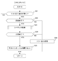
- FIG. 4A to 4C are flowcharts showing the operation of the control device 10. More specifically, FIG. 4A is a flowchart showing the operation of PLC_CPU11. FIG. 4B is a flowchart showing the operation of CNC_CPU12. FIG. 4C is a flowchart showing the sub-steps constituting the sequence processing of step S12 in the flowchart shown in FIG. 4A and the sub-steps constituting the sequence processing of step S23 in the flowchart shown in FIG. 4B.
- step S11 when the test interval time is exceeded in PLC_CPU11 in step S11 (S11: YES), the process proceeds to step S12. If the test interval time has not yet been exceeded in PLC_CPU11 (S11: NO), the process proceeds to step S11 (return).
- Step S12 PLC_CPU11 executes sequence processing.
- Step S12 is composed of eight sub-steps of steps S12A to S12H shown in FIG. 4C.
- step S12A the input signal off determination unit 114 turns off the safety signal circuit output signal in the output signal region.
- step S12B the input signal off determination unit 114 checks whether the safety signal circuit input signal in the input signal region is turned off.
- step S12C when the safety circuit input signal is off (S12C: YES), the process proceeds to step S12D. If the safety circuit input signal is not off (S12C: NO), the process proceeds to step S12E.
- step S12D the input signal on determination unit 115 turns on the safety signal circuit output signal in the output signal region.
- step S12E the input signal off determination unit 114 outputs an error. After that, the process of step S12 as a whole is completed.
- step S12F the input signal on determination unit 115 checks whether the safety signal circuit input signal in the input signal region is turned on.
- step S12G when the safety circuit input signal is on (S12G: YES), the processing of step S12 as a whole is terminated. If the safety circuit input signal is not on (S12G: NO), the process proceeds to step S12H.
- step S12H the input signal on determination unit 115 outputs an error. After that, the process of step S12 as a whole is completed.
- step S13 PLC_CPU11 notifies the CNC_CPU12 side of the test result in step S12. After that, the process returns to step S11 (return).
- step S21 when the CNC_CPU12 obtains the test completion notification from the PLC_CPU11 in step S21 (S21: YES), the process proceeds to step S22. If the CNC_CPU12 has not yet acquired the test completion notification from the PLC_CPU11 (S21: NO), the process proceeds to step S21 (return).
- step S22 when the test completion notification indicates that the first safety signal circuit test in PLC_CPU11 has been completed normally (S22: YES), the process proceeds to step S23.
- step S22: NO When it is shown that an abnormality has occurred in the first safety signal circuit test (S22: NO), the process proceeds to step S26.
- step S23 CNC_CPU12 executes sequence processing.
- step S23 in the eight sub-steps of steps S12A to S12H shown in FIG. Since it is composed of the same substeps as in step S12 except that it is replaced with "on determination unit 125", the description thereof will be omitted.
- step S24 if the sequence processing in step S23 is normally completed (S24: YES), the processing proceeds to step S25.
- step S24: NO When it is shown that an abnormality has occurred in the sequence processing in step S23 (S24: NO), the processing proceeds to step S26.
- step S25 CNC_CPU12 resets the test interval time. After that, the process returns to step S21 (return).
- step S26 CNC_CPU12 outputs the abnormality (error) shown in step S22 and step S24. After that, the process returns to step S21 (return).
- the control device (for example, the above-mentioned “control device 10") is a safety signal circuit (for example, a safety signal circuit) which is a circuit that cuts off a motor drive signal for driving a motor provided in a machine tool based on an input signal.
- a safety signal circuit for example, a safety signal circuit
- PLC_CPU11 a first control unit
- CNC_CPU12 a second control unit
- a control device for performing a test wherein the first control unit measures an elapsed time and instructs the start of a first safety signal circuit test based on the elapsed time (for example, the above-mentioned "time measuring”. Part 111 ”) and when the safety signal circuit output signal is output to the first circuit or when the output is stopped, whether or not the safety signal circuit input signal is input is detected, and the detection result is used.
- the first circuit test control unit (for example, the above-mentioned "test control unit 112") for executing the first safety signal circuit test is provided, and the second control unit is the first circuit test control unit.
- the execution confirmation unit (for example, the above-mentioned “implementation confirmation unit 121") for confirming whether or not the first safety signal circuit test has been completed and the implementation confirmation unit have completed the first safety signal circuit test. After confirmation, it is detected whether or not the safety signal circuit input signal is input when the safety signal circuit output signal is output to the second circuit or when the output is stopped, and the detection result is used to detect whether or not the safety signal circuit input signal is input. It includes a second circuit test control unit (for example, the above-mentioned "test control unit 122”) that executes a second safety signal circuit test.
- the first circuit test control unit determines whether or not to start the first safety signal circuit test (for example, the above-mentioned "test execution”.
- the safety signal circuit input signal is input to the input signal region of the first circuit.
- the safety signal circuit output signal is output to the first input signal off determination unit (for example, the above-mentioned "input signal off determination unit 114") for determining whether or not, and the output signal region of the first circuit.
- the first input signal on determination unit for example, the above-mentioned “input signal on determination unit 115" for determining whether or not the safety signal circuit input signal is input to the input signal region of the first circuit.
- the first test completion determination unit (for example, the above-mentioned “test completion determination") that determines whether or not both the determination by the first input signal off determination unit and the determination by the first input signal on determination unit are completed.
- the second circuit test control unit includes a unit 116 ”), and the second circuit test control unit determines whether or not the start of the second safety signal circuit test can be started (for example, the above-mentioned“ test execution determination unit 123 ”).
- the safety signal circuit output signal When the output of the safety signal circuit output signal with respect to the output signal region of the second circuit is stopped, it is determined whether or not the safety signal circuit input signal is input to the input signal region of the second circuit.
- the safety signal circuit output signal is output to the second input signal off determination unit (for example, the above “input signal off determination unit 124") and the output signal region of the second circuit, the first A second input signal on determination unit (for example, the above-mentioned "input signal on determination unit 125") for determining whether or not the safety signal circuit input signal is input to the input signal region of the two circuits, and the second input.
- a second test completion determination unit (for example, the above-mentioned "test completion determination unit 126") that determines whether or not both the determination by the signal off determination unit and the determination by the second input signal on determination unit are completed. , May be provided.
- the I / O signals provided in the PLC_CPU11 and the CNC_CPU12 are provided. There is no need to access the area (not shown), turn on the input signal stored in the I / O signal area, and check the output signal in the I / O signal area.
- the control method according to the present embodiment is a safety signal circuit (for example, the above-mentioned "safety signal circuit 18") which is a circuit that cuts off a motor drive signal for driving a motor provided in a machine tool based on an input signal.
- a control method for testing the safety signal circuit with a control device including a first control unit (for example, the above-mentioned "PLC_CPU11”) and a second control unit (for example, the above-mentioned "CNC_CPU12"). Therefore, the first control unit measures the elapsed time, and the timing step instructing the start of the first safety signal circuit test based on the elapsed time, and the first control unit are safe for the first circuit.
- the safety signal circuit input signal is output when the safety signal circuit output signal is output to the second circuit or when the output is stopped. It has a second circuit test control step of detecting whether or not is input and executing a second safety signal circuit test using the detection result.
- the first circuit test control step includes a first test execution determination sub-step for determining whether or not the first safety signal circuit test can be started, and the first circuit.
- First input signal off determination for determining whether or not the safety signal circuit input signal is input to the input signal region of the first circuit when the output of the safety signal circuit output signal to the output signal region is stopped. Whether or not the safety signal circuit input signal is input to the input signal area of the first circuit when the safety signal circuit output signal is output to the substep and the output signal area of the first circuit. It is determined whether or not both the determination in the first input signal on determination substep, the determination in the first input signal off determination substep, and the determination in the first input signal on determination substep are completed.
- the second circuit test control step has one test completion determination sub-step, the second test execution determination sub-step for determining whether or not the start of the second safety signal circuit test can be started, and the output signal of the second circuit.
- Second input signal off determination substep for determining whether or not the safety signal circuit input signal is input to the input signal region of the second circuit when the output of the safety signal circuit output signal to the region is stopped.
- a second test for determining whether or not both the determination in the second input signal on determination substep, the determination in the second input signal off determination substep, and the determination in the second input signal on determination substep are completed. It has a completion determination substep.
- the I / O signals provided in the PLC_CPU11 and the CNC_CPU12 are provided. There is no need to access the area (not shown), turn on the input signal stored in the I / O signal area, and check the output signal in the I / O signal area.
- the control method by the control device 10 is realized by software.
- the programs constituting the software are installed in the computer (control device 10).
- these programs may be recorded on removable media and distributed to users, or may be distributed by being downloaded to a user's computer via a network. Further, these programs may be provided to the user's computer (control device 10) as a Web service via the network without being downloaded.
- Control system 10 Control device 11 PLC_CPU (1st control unit) 12 CNC_CPU (2nd control unit) 15 I / F area 17 Storage unit 111 Timekeeping unit 112, 122 Test control unit 113,123 Test execution judgment unit 114,124 Input signal off judgment unit 115,125 Input signal on judgment unit 116,126 Test completion judgment unit
Landscapes
- Engineering & Computer Science (AREA)
- Physics & Mathematics (AREA)
- General Physics & Mathematics (AREA)
- Automation & Control Theory (AREA)
- Human Computer Interaction (AREA)
- Manufacturing & Machinery (AREA)
- Programmable Controllers (AREA)
Abstract
Description
本開示の制御方法の一態様は、入力信号に基づいて、工作機械に備わるモータを駆動するモータ駆動信号を遮断する回路である安全信号回路と、第1制御部と、第2制御部とを備える制御装置で、前記安全信号回路のテストを行うための制御方法であって、前記第1制御部が、経過時間を計測し、該経過時間に基づいて第1安全信号回路テストの開始を指示する計時ステップと、前記第1制御部が、第1回路に対し安全信号回路出力信号を出力した際又は出力を停止した際に、安全信号回路入力信号が入力されるか否かを検知し、当該検知結果を用いて、前記第1安全信号回路テストを実行する第1回路テスト制御ステップと、前記第2制御部が、前記第1回路テスト制御ステップにおいて前記第1安全信号回路テストが完了したか否かを確認する実施確認ステップと、前記第2制御部が、前記実施確認ステップにおいて、前記第1安全信号回路テストが完了したことが確認された後、第2回路に対し安全信号回路出力信号を出力した際又は出力を停止した際に、安全信号回路入力信号が入力されるか否かを検知し、当該検知結果を用いて、第2安全信号回路テストを実行する第2回路テスト制御ステップと、を有する。
図1は、本実施形態に係る制御装置を用いた、工作機械の制御システムの構成例を示す。
図2は、安全信号回路テストを実行する際の回路図の概略を示す。
図3は、制御装置10の構成を示す機能ブロック図である。制御装置10は、PLC_CPU11と、CNC_CPU12と、I/F領域15と、記憶部17と、安全信号回路18とを備える。なお、以降では、PLC_CPU11を「第1制御部11」と呼称し、CNC_CPU12を「第2制御部12」と呼称することがある。
図4A~図4Cは、制御装置10の動作を示すフローチャートである。より詳細には、図4Aは、PLC_CPU11の動作を示すフローチャートである。図4Bは、CNC_CPU12の動作を示すフローチャートである。図4Cは、図4Aに示されるフローチャート中、ステップS12のシーケンス処理を構成するサブステップ、及び図4Bに示されるフローチャート中、ステップS23のシーケンス処理を構成するサブステップを示すフローチャートである。
(1) 本実施形態に係る制御装置(例えば、上記の「制御装置10」)は、入力信号に基づいて、工作機械に備わるモータを駆動するモータ駆動信号を遮断する回路である安全信号回路(例えば、上記の「安全信号回路18」)と、第1制御部(例えば、上記の「PLC_CPU11」)と、第2制御部(例えば、上記の「CNC_CPU12」)とを備え、前記安全信号回路のテストを行うための制御装置であって、前記第1制御部は、経過時間を計測し、該経過時間に基づいて第1安全信号回路テストの開始を指示する計時部(例えば、上記の「計時部111」)と、第1回路に対し安全信号回路出力信号を出力した際又は出力を停止した際に、安全信号回路入力信号が入力されるか否かを検知し、当該検知結果を用いて、前記第1安全信号回路テストを実行する第1回路テスト制御部(例えば、上記の「テスト制御部112」)と、を備え、前記第2制御部は、前記第1回路テスト制御部による前記第1安全信号回路テストが完了したか否かを確認する実施確認部(例えば、上記の「実施確認部121」)と、前記実施確認部により、前記第1安全信号回路テストが完了したことが確認された後、第2回路に対し安全信号回路出力信号を出力した際又は出力を停止した際に、安全信号回路入力信号が入力されるか否かを検知し、当該検知結果を用いて、第2安全信号回路テストを実行する第2回路テスト制御部(例えば、上記の「テスト制御部122」)と、を備える。
10 制御装置
11 PLC_CPU(第1制御部)
12 CNC_CPU(第2制御部)
15 I/F領域
17 記憶部
111 計時部
112,122 テスト制御部
113,123 テスト実施判定部
114,124 入力信号オフ判定部
115,125 入力信号オン判定部
116,126 テスト完了判定部
Claims (4)
- 入力信号に基づいて、工作機械に備わるモータを駆動するモータ駆動信号を遮断する回路である安全信号回路と、第1制御部と、第2制御部とを備え、前記安全信号回路のテストを行うための制御装置であって、
前記第1制御部は、
経過時間を計測し、該経過時間に基づいて第1安全信号回路テストの開始を指示する計時部と、
第1回路に対し安全信号回路出力信号を出力した際又は出力を停止した際に、安全信号回路入力信号が入力されるか否かを検知し、当該検知結果を用いて、前記第1安全信号回路テストを実行する第1回路テスト制御部と、
を備え、
前記第2制御部は、
前記第1回路テスト制御部による前記第1安全信号回路テストが完了したか否かを確認する実施確認部と、
前記実施確認部により、前記第1安全信号回路テストが完了したことが確認された後、第2回路に対し安全信号回路出力信号を出力した際又は出力を停止した際に、安全信号回路入力信号が入力されるか否かを検知し、当該検知結果を用いて、第2安全信号回路テストを実行する第2回路テスト制御部と、
を備える、制御装置。 - 前記第1回路テスト制御部は、
前記第1安全信号回路テストの開始の可否を判定する第1テスト実施判定部と、
前記第1回路の出力信号領域に対する、前記安全信号回路出力信号の出力を停止した際に、前記第1回路の入力信号領域に前記安全信号回路入力信号が入力されるか否かを判定する第1入力信号オフ判定部と、
前記第1回路の出力信号領域に対して、前記安全信号回路出力信号を出力した際に、前記第1回路の入力信号領域に前記安全信号回路入力信号が入力されるか否かを判定する第1入力信号オン判定部と、
前記第1入力信号オフ判定部による判定と、前記第1入力信号オン判定部による判定の双方が完了したか否かを判定する、第1テスト完了判定部とを備え、
前記第2回路テスト制御部は、
前記第2安全信号回路テストの開始の可否を判定する第2テスト実施判定部と、
前記第2回路の出力信号領域に対する、前記安全信号回路出力信号の出力を停止した際に、前記第2回路の入力信号領域に前記安全信号回路入力信号が入力されるか否かを判定する第2入力信号オフ判定部と、
前記第2回路の出力信号領域に対して、前記安全信号回路出力信号を出力した際に、前記第2回路の入力信号領域に前記安全信号回路入力信号が入力されるか否かを判定する第2入力信号オン判定部と、
前記第2入力信号オフ判定部による判定と、前記第2入力信号オン判定部による判定の双方が完了したか否かを判定する、第2テスト完了判定部とを備える、請求項1に記載の制御装置。 - 入力信号に基づいて、工作機械に備わるモータを駆動するモータ駆動信号を遮断する回路である安全信号回路と、第1制御部と、第2制御部とを備える制御装置で、前記安全信号回路のテストを行うための制御方法であって、
前記第1制御部が、経過時間を計測し、該経過時間に基づいて第1安全信号回路テストの開始を指示する計時ステップと、
前記第1制御部が、第1回路に対し安全信号回路出力信号を出力した際又は出力を停止した際に、安全信号回路入力信号が入力されるか否かを検知し、当該検知結果を用いて、前記第1安全信号回路テストを実行する第1回路テスト制御ステップと、
前記第2制御部が、前記第1回路テスト制御ステップにおいて前記第1安全信号回路テストが完了したか否かを確認する実施確認ステップと、
前記第2制御部が、前記実施確認ステップにおいて、前記第1安全信号回路テストが完了したことが確認された後、第2回路に対し安全信号回路出力信号を出力した際又は出力を停止した際に、安全信号回路入力信号が入力されるか否かを検知し、当該検知結果を用いて、第2安全信号回路テストを実行する第2回路テスト制御ステップと、
を有する、制御方法。 - 前記第1回路テスト制御ステップは、
前記第1安全信号回路テストの開始の可否を判定する第1テスト実施判定サブステップと、
前記第1回路の出力信号領域に対する、前記安全信号回路出力信号の出力を停止した際に、前記第1回路の入力信号領域に前記安全信号回路入力信号が入力されるか否かを判定する第1入力信号オフ判定サブステップと、
前記第1回路の出力信号領域に対して、前記安全信号回路出力信号を出力した際に、前記第1回路の入力信号領域に前記安全信号回路入力信号が入力されるか否かを判定する第1入力信号オン判定サブステップと、
前記第1入力信号オフ判定サブステップにおける判定と、前記第1入力信号オン判定サブステップにおける判定の双方が完了したか否かを判定する、第1テスト完了判定サブステップとを有し、
前記第2回路テスト制御ステップは、
前記第2安全信号回路テストの開始の可否を判定する第2テスト実施判定サブステップと、
前記第2回路の出力信号領域に対する、前記安全信号回路出力信号の出力を停止した際に、前記第2回路の入力信号領域に前記安全信号回路入力信号が入力されるか否かを判定する第2入力信号オフ判定サブステップと、
前記第2回路の出力信号領域に対して、前記安全信号回路出力信号を出力した際に、前記第2回路の入力信号領域に前記安全信号回路入力信号が入力されるか否かを判定する第2入力信号オン判定サブステップと、
前記第2入力信号オフ判定サブステップにおける判定と、前記第2入力信号オン判定サブステップにおける判定の双方が完了したか否かを判定する、第2テスト完了判定サブステップとを有する、請求項3に記載の制御方法。
Priority Applications (4)
| Application Number | Priority Date | Filing Date | Title |
|---|---|---|---|
| JP2022507172A JP7414957B2 (ja) | 2020-03-13 | 2021-03-08 | 制御装置及び制御方法 |
| CN202180019797.8A CN115244475A (zh) | 2020-03-13 | 2021-03-08 | 控制装置及控制方法 |
| DE112021001635.0T DE112021001635T5 (de) | 2020-03-13 | 2021-03-08 | Steuervorrichtung und Steuerverfahren |
| US17/801,578 US12386331B2 (en) | 2020-03-13 | 2021-03-08 | Control device for performing test of safety signal circuit, and control method for performing test of safety signal circuit |
Applications Claiming Priority (2)
| Application Number | Priority Date | Filing Date | Title |
|---|---|---|---|
| JP2020-044157 | 2020-03-13 | ||
| JP2020044157 | 2020-03-13 |
Publications (1)
| Publication Number | Publication Date |
|---|---|
| WO2021182386A1 true WO2021182386A1 (ja) | 2021-09-16 |
Family
ID=77672347
Family Applications (1)
| Application Number | Title | Priority Date | Filing Date |
|---|---|---|---|
| PCT/JP2021/008960 Ceased WO2021182386A1 (ja) | 2020-03-13 | 2021-03-08 | 制御装置及び制御方法 |
Country Status (5)
| Country | Link |
|---|---|
| US (1) | US12386331B2 (ja) |
| JP (1) | JP7414957B2 (ja) |
| CN (1) | CN115244475A (ja) |
| DE (1) | DE112021001635T5 (ja) |
| WO (1) | WO2021182386A1 (ja) |
Citations (2)
| Publication number | Priority date | Publication date | Assignee | Title |
|---|---|---|---|---|
| JP2010177910A (ja) * | 2009-01-28 | 2010-08-12 | Kyocera Corp | 無線通信システム、無線基地局、無線移動局、および無線通信システムにおけるループバック試験方法 |
| JP6344500B1 (ja) * | 2017-04-21 | 2018-06-20 | 株式会社安川電機 | マトリクスコンバータ及び交流電動機の定数決定方法 |
Family Cites Families (13)
| Publication number | Priority date | Publication date | Assignee | Title |
|---|---|---|---|---|
| US6734581B1 (en) * | 1998-10-28 | 2004-05-11 | Eigenpoint Company | Programmable emergency-stop circuit with testing |
| JP2001014015A (ja) | 1999-06-28 | 2001-01-19 | Amada Eng Center Co Ltd | 工作機械の安全制御方法およびその装置 |
| DE10143816A1 (de) * | 2001-09-06 | 2003-04-03 | Nexpress Solutions Llc | Elektronische Sicherheitsschaltung |
| DE102004020997A1 (de) * | 2004-04-19 | 2005-11-03 | Pilz Gmbh & Co. Kg | Sicherheitsschalteinrichtung für eine Sicherheitsschaltung |
| JP4202335B2 (ja) | 2005-03-22 | 2008-12-24 | ファナック株式会社 | 非常停止回路 |
| DE102012103015B4 (de) * | 2012-04-05 | 2013-12-05 | Pilz Gmbh & Co. Kg | Sicherheitsschaltvorrichtung mit Schaltelement im Hilfskontaktstrompfad |
| EP2930844B1 (en) * | 2014-04-10 | 2018-07-04 | ABB Schweiz AG | Safe torque off procedure |
| JP5902778B1 (ja) * | 2014-09-03 | 2016-04-13 | ファナック株式会社 | 周辺機器を安全に制御する機能を有する工作機械 |
| JP6226914B2 (ja) * | 2015-06-12 | 2017-11-08 | ファナック株式会社 | 非常停止時にサーボモータを制御して停止させるサーボモータ停止制御装置 |
| JP6772887B2 (ja) * | 2017-02-21 | 2020-10-21 | オムロン株式会社 | サーボシステム |
| EP3462471B1 (en) * | 2017-09-29 | 2022-04-13 | Rockwell Automation Switzerland GmbH | Safety switch |
| JP6697432B2 (ja) * | 2017-12-08 | 2020-05-20 | ファナック株式会社 | 2重化されたオンオフ信号生成部を有するスイッチ装置及び数値制御システム |
| WO2022044906A1 (ja) * | 2020-08-25 | 2022-03-03 | ファナック株式会社 | ロボット制御装置 |
-
2021
- 2021-03-08 US US17/801,578 patent/US12386331B2/en active Active
- 2021-03-08 DE DE112021001635.0T patent/DE112021001635T5/de active Pending
- 2021-03-08 CN CN202180019797.8A patent/CN115244475A/zh active Pending
- 2021-03-08 WO PCT/JP2021/008960 patent/WO2021182386A1/ja not_active Ceased
- 2021-03-08 JP JP2022507172A patent/JP7414957B2/ja active Active
Patent Citations (2)
| Publication number | Priority date | Publication date | Assignee | Title |
|---|---|---|---|---|
| JP2010177910A (ja) * | 2009-01-28 | 2010-08-12 | Kyocera Corp | 無線通信システム、無線基地局、無線移動局、および無線通信システムにおけるループバック試験方法 |
| JP6344500B1 (ja) * | 2017-04-21 | 2018-06-20 | 株式会社安川電機 | マトリクスコンバータ及び交流電動機の定数決定方法 |
Also Published As
| Publication number | Publication date |
|---|---|
| JPWO2021182386A1 (ja) | 2021-09-16 |
| US20230101050A1 (en) | 2023-03-30 |
| JP7414957B2 (ja) | 2024-01-16 |
| US12386331B2 (en) | 2025-08-12 |
| DE112021001635T5 (de) | 2022-12-29 |
| CN115244475A (zh) | 2022-10-25 |
Similar Documents
| Publication | Publication Date | Title |
|---|---|---|
| JP2019169003A (ja) | 異常検知装置 | |
| CN113631851B (zh) | 安全系统和包括安全系统的材料测试系统 | |
| CN113412388B (zh) | 需要有意功能激活的安全系统和包括需要有意功能激活的安全系统的材料测试系统 | |
| JP7033114B2 (ja) | 電圧監視装置および方法 | |
| WO2018155424A1 (ja) | モータ制御装置 | |
| JP2022511793A (ja) | 安全システムインターフェース及び安全システムインターフェースを備える材料試験システム | |
| JP7000703B2 (ja) | 情報処理装置、情報処理方法、および、情報処理プログラム | |
| JP5241706B2 (ja) | 電気駆動システムの電子制御装置、電気駆動システムの電子駆動ユニットおよび電気駆動システム | |
| CN112889212B (zh) | 电磁制动器控制装置和控制装置 | |
| JP2954615B2 (ja) | モータ駆動制御装置 | |
| JP2005031778A (ja) | セーフティコントローラおよびそれを用いたシステム | |
| JP2019165533A (ja) | 制御装置 | |
| US20160062335A1 (en) | Machine tool having function of safety controlling peripheral devices | |
| JP2009104246A (ja) | プログラマブルコントローラおよびその異常時復旧方法 | |
| WO2021182386A1 (ja) | 制御装置及び制御方法 | |
| CN101198916A (zh) | 可编程控制器 | |
| US9557732B2 (en) | Numerical controller having program resuming function | |
| JP4300129B2 (ja) | プログラマブル・シーケンス制御装置 | |
| WO2019142245A1 (ja) | 信号制御装置および異常検出方法 | |
| WO2007096971A1 (ja) | 保守ガイダンス表示装置、保守ガイダンス表示方法、保守ガイダンス表示プログラム | |
| JP7560658B2 (ja) | モータの結線ミス検出装置 | |
| US20180181101A1 (en) | Numerical controller | |
| WO2019234897A1 (ja) | 数値制御装置および情報処理装置 | |
| JP7747778B2 (ja) | 産業用機械の結線異常検出装置及び制御システム | |
| US7148647B2 (en) | Numerical control device |
Legal Events
| Date | Code | Title | Description |
|---|---|---|---|
| 121 | Ep: the epo has been informed by wipo that ep was designated in this application |
Ref document number: 21767968 Country of ref document: EP Kind code of ref document: A1 |
|
| ENP | Entry into the national phase |
Ref document number: 2022507172 Country of ref document: JP Kind code of ref document: A |
|
| 122 | Ep: pct application non-entry in european phase |
Ref document number: 21767968 Country of ref document: EP Kind code of ref document: A1 |
|
| WWG | Wipo information: grant in national office |
Ref document number: 17801578 Country of ref document: US |