WO2021182368A1 - プレフィルドシリンジ及びシリンジ外筒 - Google Patents
プレフィルドシリンジ及びシリンジ外筒 Download PDFInfo
- Publication number
- WO2021182368A1 WO2021182368A1 PCT/JP2021/008869 JP2021008869W WO2021182368A1 WO 2021182368 A1 WO2021182368 A1 WO 2021182368A1 JP 2021008869 W JP2021008869 W JP 2021008869W WO 2021182368 A1 WO2021182368 A1 WO 2021182368A1
- Authority
- WO
- WIPO (PCT)
- Prior art keywords
- chamber
- outer cylinder
- syringe
- peripheral surface
- inner peripheral
- Prior art date
- Legal status (The legal status is an assumption and is not a legal conclusion. Google has not performed a legal analysis and makes no representation as to the accuracy of the status listed.)
- Ceased
Links
Images





Classifications
-
- A—HUMAN NECESSITIES
- A61—MEDICAL OR VETERINARY SCIENCE; HYGIENE
- A61M—DEVICES FOR INTRODUCING MEDIA INTO, OR ONTO, THE BODY; DEVICES FOR TRANSDUCING BODY MEDIA OR FOR TAKING MEDIA FROM THE BODY; DEVICES FOR PRODUCING OR ENDING SLEEP OR STUPOR
- A61M5/00—Devices for bringing media into the body in a subcutaneous, intra-vascular or intramuscular way; Accessories therefor, e.g. filling or cleaning devices, arm-rests
- A61M5/178—Syringes
- A61M5/19—Syringes having more than one chamber, e.g. including a manifold coupling two parallelly aligned syringes through separate channels to a common discharge assembly
-
- A—HUMAN NECESSITIES
- A61—MEDICAL OR VETERINARY SCIENCE; HYGIENE
- A61M—DEVICES FOR INTRODUCING MEDIA INTO, OR ONTO, THE BODY; DEVICES FOR TRANSDUCING BODY MEDIA OR FOR TAKING MEDIA FROM THE BODY; DEVICES FOR PRODUCING OR ENDING SLEEP OR STUPOR
- A61M5/00—Devices for bringing media into the body in a subcutaneous, intra-vascular or intramuscular way; Accessories therefor, e.g. filling or cleaning devices, arm-rests
- A61M5/178—Syringes
- A61M5/28—Syringe ampoules or carpules, i.e. ampoules or carpules provided with a needle
Definitions
- the present invention relates to a prefilled syringe and a syringe outer cylinder.
- prefilled syringe equipped with two chambers as one of the mixing devices that mixes two kinds of chemicals at the time of use just before use.
- this prefilled syringe for example, as shown in Japanese Patent Application Laid-Open No. 2013-75154, the storage space inside the outer cylinder of the syringe is separated into two chambers by an intermediate gasket, and different types of chemicals are used in each chamber. Is enclosed.
- a bypass flow path is formed near the center of the outer cylinder of the syringe so as to project outward in the radial direction. By moving the intermediate gasket to the position of the bypass flow path immediately before use, two chambers are formed. The chemicals enclosed in the can be mixed.
- the above-mentioned prefilled syringe also has an administration function as a syringe and can be used as it is after mixing, so that it is a simple and highly safe mixing device.
- the conventional prefilled syringe has a bypass flow path provided at one place in the circumferential direction, and has a problem that the mixing property is poor when mixing chemicals in a narrow space inside the syringe.
- water flows in from only one place in the circumferential direction, so depending on the properties of the powder, It may take time to mix.
- bypass flow path part appears as a convex portion on the outer surface of the syringe outer cylinder. Since a label cannot be attached to this convex portion, the display area by the label is restricted. In addition, it may be necessary to attach two labels so as to avoid the convex portion.
- bypass flow path is formed in a concave shape in order to form a liquid flow path on the inner peripheral surface of the syringe outer cylinder, but when such a flow path is formed of a resin material, it is die-cut. Since it is necessary to devise and use a mold having a special structure, there are restrictions on reducing the inner diameter size of the syringe.
- One aspect of the present invention is that a storage space for storing a drug is formed inside, and the syringe outer cylinder having a nozzle at the tip and the storage space of the syringe outer cylinder are divided into two chambers, a first medicine chamber and a second medicine chamber.
- the intermediate gasket separated from the nozzle, the proximal gasket arranged on the proximal side of the intermediate gasket, and the inner peripheral surface of the syringe outer cylinder, which are provided at intermediate positions separated from the nozzle to the proximal end side.
- a bypass structure for forming a gap between the outer peripheral portion of the intermediate gasket and communicating the first drug chamber and the second drug chamber is provided, and the tip portion of the bypass structure is the circumference of the inner peripheral surface. It is in a prefilled syringe that is formed in multiple places or over the entire area in the direction.
- a gasket outer cylinder used for a prefilled syringe that communicates the first chamber and the second chamber to mix internal chemicals, and has a nozzle provided at the tip and a tubular body. A portion, a proximal end side opening formed on the proximal end side of the body portion, a storage space formed on the body portion, and an inner peripheral surface of the body portion, from the nozzle to the proximal end side.
- the tip of the bypass structure is provided with a bypass structure provided at a separated intermediate position and forming a gap between the outer peripheral portion of the intermediate gasket to communicate the first chamber and the second chamber.
- the portion is in the outer cylinder of the syringe, which is formed over a plurality of places or the entire area in the circumferential direction of the inner peripheral surface.
- the mixing property is excellent, the inner diameter size can be reduced, and the convex portion does not appear on the outer surface.
- FIG. 6A to 6D are cross-sectional views showing the mixing procedure using the prefilled syringe of FIG. 1 in order of steps. It is a perspective sectional view of the syringe outer cylinder which concerns on 2nd Embodiment.
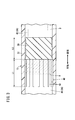
- FIG. 9A is a perspective cross-sectional view of the syringe outer cylinder according to the fourth embodiment
- FIG. 9B is a cross-sectional view in a state where an intermediate gasket is arranged in the bypass structure of the syringe outer cylinder of FIG. 9A.
- FIG. 10 is a partially enlarged cross-sectional view of the vicinity of the bypass structure of the syringe outer cylinder of FIG.
- the prefilled syringe 10 has a syringe outer cylinder 12 formed of a hollow body provided with a nozzle 14 and a needle unit 16 mounted on the nozzle 14 of the syringe outer cylinder 12 as main components.
- a pusher 18 for pushing gaskets 38 and 40 (see FIG. 2) in the syringe outer cylinder 12 toward the nozzle 14 is provided.
- the syringe outer cylinder 12 has a substantially cylindrical shape, and has a body portion 22 having a base end side opening 20 formed therein and a nozzle 14 provided at the tip of the body portion 22 on the base end side. As shown in FIG. 2, a lock adapter 24 is provided on the outside of the nozzle 14. Further, a flange 26 is formed at the base end of the body portion 22 so as to project outward in the radial direction. In the syringe outer cylinder 12, the body portion 22, the nozzle 14, the lock adapter 24, and the flange 26 are integrally molded.
- the needle unit 16 is attached to the nozzle 14.
- the needle unit 16 has a needle tube 30 having a sharp needle tip 28 that can puncture the skin of a living body, and a needle hub 32 that holds a proximal end portion of the needle tube 30.
- the base end portion of the needle hub 32 is attached to the nozzle 14.
- the needle hub 32 of the needle unit 16 is equipped with a cap 34 that covers the needle tip 28. The cap 34 is removed from the needle hub 32 immediately before use.
- a storage space 36 having a circular cross section surrounded by an inner peripheral surface 12a is formed so as to penetrate in the axial direction.
- the distal end side of the accommodating space 36 communicates with the nozzle 14, and the proximal end side of the accommodating space 36 opens at the proximal end side opening 20.
- An intermediate gasket 38 and a proximal gasket 40 are inserted into the accommodation space 36 of the syringe outer cylinder 12 via the proximal end side opening 20.
- the intermediate gasket 38 and the base end gasket 40 are made of an elastic material such as a rubber material.
- the outer peripheral portion of the intermediate gasket 38 and the proximal end gasket 40 are in close contact with the inner peripheral surface 12a of the syringe outer cylinder 12 and are slidably arranged in the syringe outer cylinder 12.
- the intermediate gasket 38 is arranged near the center of the accommodating space 36, and divides the accommodating space 36 into a first chamber 42 on the proximal end side and a second chamber 44 on the distal end side.
- the base end side of the second chamber 44 is sealed by an intermediate gasket 38.
- the tip side of the first chamber 42 is sealed by the intermediate gasket 38, and the base end side is sealed by the base end gasket 40.
- the first chamber 42 contains the drug B
- the second chamber 44 contains the drug A.
- Agent A is in liquid, gel or powder form.
- the drug B is liquid and can be, for example, diluted water for dilution. As will be described later, the drug B is mixed with the drug A immediately before use.
- the intermediate gasket 38 is arranged at the base end side of the bypass structure 46, which will be described later, in the initial position so as to partition the first chamber 42 and the second chamber 44 in a liquid-tight manner until it is used.
- the tip of the pusher 18 is connected to the base end gasket 40.
- the base end gasket 40 slides in the syringe outer cylinder 12 toward the tip. Further, as the base end gasket 40 slides, the intermediate gasket 38 slides so as to be pushed out toward the tip end side.
- the pusher 18 may be connected to the proximal gasket 40 when the drugs A and B are administered to the patient. Further, the pusher 18 may be configured as long as it can press the base end gasket 40 toward the tip end, and is not connected to the base end gasket 40 but simply abuts on the base end gasket 40.
- a bypass structure 46 is formed on the inner peripheral surface 12a near the center of the syringe outer cylinder 12.
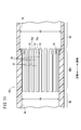
- the bypass structure 46 of the present embodiment includes a plurality of groove portions 48 formed so as to be recessed with respect to the inner peripheral surface 12a.
- the groove 48 extends in a direction parallel to the axial direction of the syringe outer cylinder 12.
- the groove portion 48 forms a gap through which the drug B can pass on the outside of the outer peripheral surface of the intermediate gasket 38, and the width dimension thereof is, for example, 0.1 mm to 2 mm, more preferably 0.3 mm to 1 mm. be able to.
- the depth of the groove 48 can be, for example, about 0.1 mm to 1 mm, more preferably about 0.2 mm to 0.4 mm.
- the ratio (width / depth) of the width to the depth of the groove portion 48 can be, for example, 0.5 to 5, preferably 1 to 2.
- the axial length L1 of the groove portion 48 is formed to be slightly longer than the axial length L2 of the intermediate gasket 38.
- the length L1 of the groove portion 48 is preferably formed to be 1 mm or more longer than the length L2 of the intermediate gasket 38.
- a plurality of groove portions 48 are arranged at regular intervals in the circumferential direction.
- the number of grooves 48 may be two or more, and can be appropriately increased or decreased according to the volume of the accommodation space 36 of the syringe outer cylinder 12 and the viscosity of the drug B.
- the number of grooves 48 may be 8 to 24.
- the volume of the storage space 36 of the syringe outer cylinder 12 is 5 ml, 16 to 48 grooves 48 may be provided.
- the prefilled syringe 10 of the present embodiment is configured as described above, and a method of manufacturing the syringe outer cylinder 12 will be described below.
- the body portion 22, the nozzle 14, the lock adapter 24, and the flange 26 constituting the syringe outer cylinder 12 are integrally formed by injection molding the resin material.
- a process of forming a groove 48 is performed on the accommodation space 36 inside the body 22.
- the processing for forming the groove portion 48 can be performed, for example, by laser processing using the processing jig 50 shown in FIG.
- the processing jig 50 is a tubular member having an outer diameter smaller than the inner diameter of the accommodation space 36 of the syringe outer cylinder 12, and the tip side of the hollow portion 52 inside the processing jig 50 is inclined by 45 ° with respect to the axial direction.
- the mirror 54 is provided.
- An irradiation window 56 formed by cutting out an outer peripheral portion is provided on the side of the mirror 54.
- the processing jig 50 is used by being inserted into the accommodation space 36 from the base end side opening 20 of the syringe outer cylinder 12.
- the laser beam 58 When the laser beam 58 is irradiated axially from the base end side of the processing jig 50, the laser beam 58 is reflected by the mirror 54, and the laser beam 58 irradiates the inner peripheral surface 12a of the syringe outer cylinder 12 through the irradiation window 56. Will be done.
- the processing jig 50 When the processing jig 50 is moved in the axial direction while irradiating the laser beam 58, the portion irradiated with the laser beam 58 becomes a linear groove 48.
- either the processing jig 50 or the syringe outer cylinder 12 is rotated by a predetermined angle around the axis, and the processing jig 50 is moved in the axial direction while irradiating the laser beam 58 again. By doing so, the second groove portion 48 can be formed.
- a desired number of grooves 48 are formed on the inner peripheral surface 12a of the syringe outer cylinder 12, and the bypass structure 46 is completed.
- the syringe outer cylinder 12 of the present embodiment is completed by removing the dust generated by the laser processing by performing a cleaning treatment on the syringe outer cylinder 12.
- the processing method for forming the groove portion 48 is not limited to the one using the laser beam 58, and may be performed by machining such as cutting.
- the prefilled syringe 10 is used after a procedure (mixing procedure) for mixing the drug A and the drug B is performed immediately before use.
- a procedure mixing procedure
- the mixing procedure of the drug A and the drug B is performed with the tip on the upper side and the base end on the lower side.
- the intermediate gasket 38 is in the initial position and is arranged on the proximal end side (lower side) of the bypass structure 46.
- the base end gasket 40 slides toward the tip end side (upper side).
- the intermediate gasket 38 is displaced so as to be pushed out to the tip end side (upper side) via the drug B in the first chamber 42.
- the intermediate gasket 38 is displaced to a position where it overlaps with the bypass structure 46. In this state, the outer peripheral surface of the intermediate gasket 38 cannot be in close contact with the groove 48, so that the first chamber 42 and the second chamber 44 communicate with each other via the groove 48 of the bypass structure 46.
- the drug B of the first chamber 42 shifts to the second chamber 44 through the groove 48 of the bypass structure 46. Since the groove portions 48 are provided at a plurality of locations in the circumferential direction, the agent A and the agent B are mixed at the plurality of locations in the circumferential direction.
- the drug A is a powder, it may become lumpy at the points where it comes into contact with the liquid drug B and the mixing property may be lowered.
- the liquid is liquid from a plurality of places in the circumferential direction.
- the prefilled syringe 10 and the syringe outer cylinder 12 of the present embodiment have the following effects.
- a storage space 36 for storing a drug is formed inside, and a syringe outer cylinder 12 having a nozzle 14 at the tip and a storage space 36 of the syringe outer cylinder 12 are provided in the first medicine chamber 42 and the first medicine chamber 42.
- a bypass structure 46 is provided at an intermediate position separated from the above, and a gap is formed between the intermediate gasket 38 and the outer peripheral portion of the intermediate gasket 38 to communicate the first medicine chamber 42 and the second medicine chamber 44.
- the tip portion of the inner peripheral surface 12a is formed at a plurality of locations in the circumferential direction or over the entire area.
- the drug B in the first chamber 42 comes into contact with the drug A in the second chamber 44 from a plurality of locations in the circumferential direction, the drug B and the drug A are mixed more uniformly, resulting in a mixture. Excellent. Further, since the gaps are dispersedly provided at a plurality of locations in the circumferential direction, the individual gaps can be reduced. As a result, it is not necessary to provide a large flow path so as to project to the outer peripheral side, and the bypass structure 46 can be provided in the syringe having a smaller inner diameter.
- the tip portion of the bypass structure 46 is formed by extending in the axial direction on the inner peripheral surface 12a of the syringe outer cylinder 12, and is formed by a plurality of groove portions 48 arranged at intervals in the circumferential direction. It may be configured. With such a configuration, processing becomes easy, and the bypass structure 46 can be provided for the prefilled syringe 10 having a smaller inner diameter.
- the axial length L1 of the groove 48 is longer than the axial length L2 of the intermediate gasket 38, and the axial length of the proximal gasket 40 and the axial length of the intermediate gasket 38. It may be formed shorter than the sum of Sato.
- the syringe outer cylinder 12 of the present embodiment has a first chamber 42 and a second chamber 44 separated by an intermediate gasket 38, and different agents are used in the first chamber 42 and the second chamber 44.
- a and B are sealed and used for a prefilled syringe 10 in which the first chamber 42 and the second chamber 44 are communicated with each other immediately before use to mix the internal agents A and B.
- the syringe outer cylinder 12 has a nozzle 14 provided at the tip, a tubular body portion 22, a base end side opening 20 formed on the base end side of the body portion 22, and a body portion 22.
- a gap is formed between the formed accommodating space 36 and the inner peripheral surface 12a of the body portion 22 at an intermediate position separated from the nozzle 14 toward the proximal end side and the outer peripheral portion of the intermediate gasket 38.
- a bypass structure 46 for communicating the first chamber 42 and the second chamber 44 is provided. The tip of the bypass structure 46 of the syringe outer cylinder 12 is formed over a plurality of locations or the entire area of the inner peripheral surface 12a in the circumferential direction.
- the mixing property of the drug B in the first chamber 42 and the drug A in the second chamber 44 is improved. Further, since the flow path can be reduced by dispersing the bypass structure 46 in the circumferential direction, it is not necessary to provide an outwardly projecting structure of the syringe outer cylinder 12. Further, since the bypass structure 46 can be easily manufactured, the bypass structure 46 can be formed on the syringe outer cylinder 12 having a smaller inner diameter.
- the present embodiment is different from the syringe outer cylinder 12 shown in FIG. 1 in the bypass structure 46A formed on the inner peripheral surface 12a of the syringe outer cylinder 12A.
- the same components as those of the syringe outer cylinder 12 shown in FIG. 1 are designated by the same reference numerals, and detailed description thereof will be omitted.
- the bypass structure 46A of the present embodiment includes a plurality of linear groove portions 48A inclined with respect to the axial direction of the syringe outer cylinder 12A.
- the groove portion 48A is formed in a spiral shape.
- the width, depth, and axial length of the groove 48A are the same as those of the groove 48 described with reference to FIG.
- the number of the groove portions 48A in the circumferential direction can be the same as that of the groove portions 48 of the first embodiment.
- the groove portion 48A of the present embodiment rotates the syringe outer cylinder 12A in the circumferential direction while moving the processing jig 50 in the axial direction. It can be formed by making it.
- the syringe outer cylinder 12A of the present embodiment is configured as described above, and when applied to the prefilled syringe 10, has the same effect as the syringe outer cylinder 12 of the first embodiment.
- the present embodiment is different from the syringe outer cylinder 12 shown in FIG. 1 in the bypass structure 46B formed on the inner peripheral surface 12a of the syringe outer cylinder 12B.
- the same components as those of the syringe outer cylinder 12 shown in FIG. 1 are designated by the same reference numerals, and detailed description thereof will be omitted.
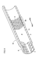
- the bypass structure 46B of the present embodiment is composed of a fine concavo-convex structure 60 formed on the inner peripheral surface 12a of the syringe outer cylinder 12B.
- the fine concavo-convex structure 60 is formed so that the length in the axial direction is longer than the length in the axial direction of the intermediate gasket 38.
- the fine concavo-convex structure 60 can be formed, for example, by performing shot blasting on the inner peripheral surface 12a of the syringe outer cylinder 12B.
- the surface roughness Ra (arithmetic mean roughness) of the fine concavo-convex structure 60 can be, for example, 1 ⁇ m to 100 ⁇ m, and more preferably 20 ⁇ m to 50 ⁇ m.
- Such a fine concavo-convex structure 60 can communicate the first chamber 42 and the second chamber 44 by preventing the outer peripheral portion of the intermediate gasket 38 from coming into close contact with the inner peripheral surface 12a of the syringe outer cylinder 12B. ..
- the fine concavo-convex structure 60 is not limited to the one formed in the entire area in the circumferential direction, and may be formed in a plurality of strip-shaped regions having a constant width in the circumferential direction.
- the syringe outer cylinder 12B of the present embodiment is configured as described above, and when applied to the prefilled syringe 10, has the same effect as the syringe outer cylinder 12 of the first embodiment.
- the present embodiment is different from the syringe outer cylinder 12 shown in FIG. 1 in the bypass structure 46C formed on the inner peripheral surface 12a of the syringe outer cylinder 12C.
- the same components as those of the syringe outer cylinder 12 shown in FIG. 1 are designated by the same reference numerals, and detailed description thereof will be omitted.
- the bypass structure 46C of the present embodiment includes a plurality of linear protrusions 62 protruding from the inner peripheral surface 12a of the syringe outer cylinder 12C and extending in the axial direction.
- Each protrusion 62 extends in the axial direction of the syringe outer cylinder 12C.
- the axial length of the protrusion 62 is formed to be slightly longer than the length of the intermediate gasket 38.
- a gap 64 is formed between the intermediate gasket 38 and the inner peripheral surface 12a of the syringe outer cylinder 12C by the protrusion 62. Since the gap 64 is formed so as to extend in the axial direction along the protrusion 62, the first chamber 42 and the second chamber 44 can be communicated with each other by the gap 64.
- the syringe outer cylinder 12C of the present embodiment also has the same effect as the syringe outer cylinder 12 of the first embodiment.
- the syringe outer cylinder 12D is formed with a first inner diameter portion 66 formed on the distal end side and an inner diameter portion formed on the proximal end side and larger than the first inner diameter portion 66. It includes a second inner diameter portion 68, and a bypass structure 46D provided between the first inner diameter portion 66 and the second inner diameter portion 68.
- the first inner diameter portion 66 is a portion having a circular inner peripheral surface 76 formed on the first inner diameter D1.
- the inner peripheral surface 76 is formed by a smooth surface, and the intermediate gasket 38 and the base end gasket 40 (see FIG. 2) are formed to have an inner diameter slidable in the axial direction while being in close contact with each other in a liquid-tight manner.
- the second inner diameter portion 68 is formed on the base end side of the first inner diameter portion 66 with the bypass structure 46D interposed therebetween.
- the second inner diameter portion 68 is a portion having a circular inner peripheral surface 78 formed on the second inner diameter D2, which is larger than the first inner diameter D1.
- the inner peripheral surface 78 extends to the base end side opening 20 (see FIG. 2).
- the inner peripheral surface 78 is a portion where the intermediate gasket 38 and the base end gasket 40 are arranged in the initial state.
- the second inner diameter D2 is formed so as to be slidable in the axial direction while the intermediate gasket 38 and the base end gasket 40 are in close contact with the inner peripheral surface 78 in a liquid-tight manner.
- the bypass structure 46D is provided between the first inner diameter portion 66 and the second inner diameter portion 68.
- the axial length of the bypass structure 46D is formed to be longer than the axial length of the intermediate gasket 38.
- the bypass structure 46D has an inner peripheral surface 74 formed on the same first inner diameter D1 as the inner peripheral surface 76 of the first inner diameter portion 66.
- the inner peripheral surface 74 and the inner peripheral surface 76 are integrally connected.
- the inner peripheral surface 74 is provided with a plurality of groove portions 70 extending in the axial direction.
- the groove portion 70 is formed to a depth corresponding to the difference between the first inner diameter D1 and the second inner diameter D2.
- the bottom surface 70a of the groove 70 is formed as a curved surface having the same inner diameter as the inner peripheral surface 78 of the second inner diameter portion 68.
- the bottom surface 70a and the inner peripheral surface 78 are integrally connected.
- a plurality of groove portions 70 are arranged at regular intervals in the circumferential direction.
- An inclined surface 72 connected to the inner peripheral surface 78 is formed at the end portion of the bypass structure 46D on the base end side of the inner peripheral surface 74.
- the inclined surface 72 is configured so that the intermediate gasket 38 and the proximal gasket 40 can easily ride on the inner peripheral surface 74, and the intermediate gasket 38 and the proximal gasket 40 can be smoothly slid.
- the intermediate gasket 38 moves to the bypass structure 46D, the outer peripheral surface of the intermediate gasket 38 is separated from the syringe outer cylinder 12D at the groove 70. As a result, the drug B can be circulated between the base end side and the tip end side of the intermediate gasket 38 through the groove portion 70.
- a bypass structure 46D through which the drug B can flow can be formed on the outside of the intermediate gasket 38 without providing a structure protruding inward on the axially proximal side in the accommodation space 36. ..
- mass production can be performed at low cost by injection molding using a mold. That is, when molding the syringe outer cylinder 12D, a step of pulling out the mold corresponding to the accommodation space 36 from the base end opening of the molded syringe outer cylinder 12D is required.
- the syringe outer cylinder 12D can be mass-produced at low cost by injection molding or the like.
- the bypass structure may be branched in the middle, and the tip of the bypass structure may be configured to open at a plurality of locations in the circumferential direction of the second chamber 44.
Landscapes
- Health & Medical Sciences (AREA)
- Vascular Medicine (AREA)
- Engineering & Computer Science (AREA)
- Anesthesiology (AREA)
- Biomedical Technology (AREA)
- Heart & Thoracic Surgery (AREA)
- Hematology (AREA)
- Life Sciences & Earth Sciences (AREA)
- Animal Behavior & Ethology (AREA)
- General Health & Medical Sciences (AREA)
- Public Health (AREA)
- Veterinary Medicine (AREA)
- Infusion, Injection, And Reservoir Apparatuses (AREA)
Abstract
プレフィルドシリンジ(10)は、内部に薬剤を収容する収容空間(36)が形成され、先端にノズル(14)を有するシリンジ外筒(12)と、シリンジ外筒(12)の収容空間(36)を第1薬室(42)及び第2薬室(44)の2室に隔てる中間ガスケット(38)と、中間ガスケット(38)の基端側に配置される基端ガスケット(40)と、シリンジ外筒(12)の内周面(12a)であって、ノズル(14)から基端側に離間した中間位置に設けられ、中間ガスケット(38)の外周部との間に隙間を形成して第1薬室(42)と第2薬室(44)とを連通させるバイパス構造(46)と、を備え、バイパス構造(46)は、内周面(12a)の周方向の複数個所に形成されている。
Description
本発明は、プレフィルドシリンジ及びシリンジ外筒に関する。
使用直前に2種類の薬品を用時混合する混合デバイスの一つとして、2つの薬室を備えたプレフィルドシリンジがある。このプレフィルドシリンジは、例えば特開2013-75154号公報に示されるように、シリンジ外筒の内部の収容空間が中間ガスケットで2つの薬室に隔てられており、それぞれの薬室に異なる種類の薬品が封入されている。シリンジ外筒の中央付近には、径方向外側に張り出すようにして設けられたバイパス流路が形成されており、使用する直前に中間ガスケットをバイパス流路の位置に移動させることで、2室に封入されている薬品を混合させることができる。また、上記のプレフィルドシリンジは、シリンジとしての投与機能も備えており、混合後にそのまま使用できるため、簡便で安全性の高い混合デバイスとなっている。
しかしながら、従来のプレフィルドシリンジは、バイパス流路が周方向の1箇所に設けられており、シリンジ内の狭い空間で薬品を混合する際の混合性が悪いという問題がある。例えば、一方の薬室に粉剤が封入され、他方の薬室に希釈用の水が封入されている場合には、周方向の一か所のみから水が流入するため、粉剤の性状によっては、混合に手間取る場合がある。
また、バイパス流路の部分が、シリンジ外筒の外面に凸部として現われる。この凸部にはラベルを貼り付けることができないため、ラベルによる表示エリアが制約される。また、凸部を避けるように、ラベルを2枚貼付しなければならない場合もある。
さらに、バイパス流路は、シリンジ外筒の内周面において液体の流路を形成するべく、凹状に形成されているが、樹脂素材でこのような流路を成形する場合には、型抜きに工夫が必要となり、特殊な構造の金型を用いる必要があるため、シリンジの内径サイズの小型化に制約が生じる。
そのため、混合性に優れ、内径サイズの小型化が可能であり、且つ外面に凸部が現われないプレフィルドシリンジ及びシリンジ外筒が求められている。
本発明の一観点は、内部に薬剤を収容する収容空間が形成され、先端にノズルを有するシリンジ外筒と、前記シリンジ外筒の前記収容空間を第1薬室及び第2薬室の2室に隔てる中間ガスケットと、前記中間ガスケットの基端側に配置される基端ガスケットと、前記シリンジ外筒の内周面であって、前記ノズルから基端側に離間した中間位置に設けられ、前記中間ガスケットの外周部との間に隙間を形成して前記第1薬室と前記第2薬室とを連通させるバイパス構造と、を備え、前記バイパス構造の先端部は、前記内周面の周方向の複数個所又は全域に亘って形成されている、プレフィルドシリンジにある。
本発明の別の一観点は、中間ガスケットによって隔てられた第1薬室と第2薬室とを有し、前記第1薬室と前記第2薬室とに異なる薬剤が封入され、使用直前に前記第1薬室と前記第2薬室とを連通させて内部の薬剤を混合させるプレフィルドシリンジに用いられるシリンジ外筒であって、先端に設けられたノズルと、筒状に形成された胴体部と、前記胴体部の基端側に形成された基端側開口部と、前記胴体部に形成された収容空間と、前記胴体部の内周面であって、前記ノズルから基端側に離間した中間位置に設けられ、前記中間ガスケットの外周部との間に隙間を形成して前記第1薬室と前記第2薬室とを連通させるバイパス構造と、を備え、前記バイパス構造の先端部は、前記内周面の周方向の複数個所又は全域に亘って形成されている、シリンジ外筒にある。
上記観点のプレフィルドシリンジ及びシリンジ外筒によれば、混合性に優れ、内径サイズの小型化が可能であり、且つ外面に凸部が現われない。
以下、本発明の好適な実施形態を挙げ、添付の図面を参照して詳細に説明する。
(第1実施形態)
図1に示す本実施形態に係るプレフィルドシリンジ10は、主たる構成要素として、ノズル14が設けられた中空体からなるシリンジ外筒12と、シリンジ外筒12のノズル14に装着された針ユニット16と、シリンジ外筒12内のガスケット38、40(図2参照)をノズル14側に押し出す押し子18と、を備える。
図1に示す本実施形態に係るプレフィルドシリンジ10は、主たる構成要素として、ノズル14が設けられた中空体からなるシリンジ外筒12と、シリンジ外筒12のノズル14に装着された針ユニット16と、シリンジ外筒12内のガスケット38、40(図2参照)をノズル14側に押し出す押し子18と、を備える。
シリンジ外筒12は、略円筒形状をなし、基端側には、基端側開口部20が形成された胴体部22と、胴体部22の先端に設けられたノズル14とを有する。図2に示すように、ノズル14の外側にはロックアダプタ24が設けられている。また、胴体部22の基端には、径方向外方に向けて突出したフランジ26が形成されている。シリンジ外筒12において、胴体部22、ノズル14、ロックアダプタ24及びフランジ26は一体的に成形されている。
ノズル14には、針ユニット16が装着されている。針ユニット16は、生体の皮膚に穿刺可能な鋭利な針先28を備えた針管30と、針管30の基端部を保持する針ハブ32とを有している。針ハブ32の基端部がノズル14に装着されている。また、針ユニット16の針ハブ32には、針先28を覆うキャップ34が装着されている。キャップ34は使用直前に針ハブ32から取り外される。
シリンジ外筒12の内部には、内周面12aによって囲まれた断面が円形の収容空間36が軸方向に貫通して形成されている。収容空間36の先端側は、ノズル14に連通し、収容空間36の基端側は基端側開口部20において開口する。
シリンジ外筒12の収容空間36には、基端側開口部20を介して中間ガスケット38及び基端ガスケット40が挿入されている。中間ガスケット38及び基端ガスケット40は、例えばゴム材等の弾性材料により構成されている。中間ガスケット38及び基端ガスケット40は、その外周部がシリンジ外筒12の内周面12aに液密に接するとともに、シリンジ外筒12内に摺動可能に配置されている。
中間ガスケット38は、収容空間36の中央付近に配置されており、収容空間36を基端側の第1薬室42と先端側の第2薬室44とに仕切る。第2薬室44の基端側は、中間ガスケット38により封じられている。また、第1薬室42は先端側が中間ガスケット38によって封じられ、基端側が基端ガスケット40により封じられている。第1薬室42には薬剤Bが封入され、第2薬室44には薬剤Aが封入されている。薬剤Aは、液状、ゲル状又は粉末状である。薬剤Bは液状であり、例えば、希釈するための希釈水とすることができる。後述するように、薬剤Bは使用直前に薬剤Aと混合される。なお、中間ガスケット38は、使用するまで第1薬室42と第2薬室44とを液密に仕切るべく、初期位置においては、後述するバイパス構造46の基端側に配置されている。
基端ガスケット40には、押し子18の先端部が連結されている。ユーザが押し子18を先端方向に押圧することにより、基端ガスケット40がシリンジ外筒12内を先端方向に摺動する。また、基端ガスケット40の摺動に伴って、中間ガスケット38が先端側に押し出されるように摺動する。
押し子18は、薬剤A、Bを患者に投与するときに基端ガスケット40に連結されてもよい。また、押し子18は、基端ガスケット40を先端方向に押圧可能であればよく、基端ガスケット40に連結されず、単に基端ガスケット40に当接する構成でもよい。
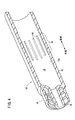
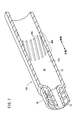
シリンジ外筒12の中央付近の内周面12aには、バイパス構造46が形成されている。図3に示すように、本実施形態のバイパス構造46は、内周面12aに対して凹むように形成された複数本の溝部48を備える。溝部48は、シリンジ外筒12の軸方向と平行な向きに延びている。溝部48は、中間ガスケット38の外周面の外側に薬剤Bが通過可能な隙間を形成するものであり、その幅の寸法は、例えば0.1mm~2mm、より好ましくは0.3mm~1mmとすることができる。また、溝部48の深さは、例えば、0.1mm~1mm、より好ましくは0.2mm~0.4mm程度とすることができる。溝部48の幅と深さとの比(幅/深さ)は、例えば0.5~5とすることができ、好ましくは1~2とすることができる。
また、溝部48の軸方向の長さL1は中間ガスケット38の軸方向の長さL2よりも僅かに長く形成されている。溝部48の長さL1は、中間ガスケット38の長さL2よりも、1mm以上長く形成されていることが好ましい。
図4に示すように、溝部48は、周方向に一定間隔をあけて複数本配置されている。溝部48の本数は、2本以上あればよく、シリンジ外筒12の収容空間36の容積及び薬剤Bの粘性に応じて適宜増減させることができる。例えば、シリンジ外筒12の収容空間36の容積が2.25mlの場合には溝部48を8~24本とすればよい。また、シリンジ外筒12の収容空間36の容積が5mlの場合には、溝部48を16~48本設ければよい。
本実施形態のプレフィルドシリンジ10は、以上のように構成され、以下、そのシリンジ外筒12の製造方法について説明する。
まず、樹脂素材を射出成形することにより、シリンジ外筒12を構成する胴体部22、ノズル14、ロックアダプタ24及びフランジ26を一体的に形成する。次に、胴体部22の内部の収容空間36に対して溝部48を形成する加工を施す。
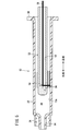
溝部48を形成する加工は、例えば、図5に示す加工治具50を用いたレーザ加工で行うことができる。加工治具50は、シリンジ外筒12の収容空間36の内径よりも小さな外径を有する筒状の部材であり、その内部の中空部52の先端側には、軸方向に対して45°傾斜したミラー54が設けられている。ミラー54の側方には、外周部を切り欠いて形成された照射窓56が設けられている。加工治具50は、シリンジ外筒12の基端側開口部20から収容空間36に挿入して用いられる。加工治具50の基端側から軸方向にレーザ光58を照射すると、ミラー54によりレーザ光58が反射され、照射窓56を介してシリンジ外筒12の内周面12aにレーザ光58が照射される。レーザ光58を照射しつつ加工治具50を軸方向に移動させると、レーザ光58で照射された部分が線状の溝部48となる。
1本の溝部48が完成した後、加工治具50又はシリンジ外筒12のいずれか一方を軸回りに所定角度回転させて、再びレーザ光58を照射しつつ加工治具50を軸方向に移動させることで、2本目の溝部48を形成できる。以上の動作を複数回繰り返すことで、所望の本数の溝部48がシリンジ外筒12の内周面12aに形成され、バイパス構造46が完成する。
その後、シリンジ外筒12に対して洗浄処理を行うことで、レーザ加工によって生じた粉塵を除去することで、本実施形態のシリンジ外筒12が完成する。なお、溝部48を形成する加工方法はレーザ光58を用いるものに限定されず、例えば切削加工等の機械加工によって行ってもよい。
次に、本実施形態のプレフィルドシリンジ10の作用について説明する。
プレフィルドシリンジ10は、使用直前に薬剤Aと薬剤Bとを混合させる手技(混合手技)が行われた後、使用に供される。薬剤Aと薬剤Bとの混合手技は、図6Aに示すように、先端を上側に、基端を下側に配置した状態で行う。図6Aでは、中間ガスケット38は初期位置にあり、バイパス構造46よりも基端側(下側)に配置されている。この初期位置から、押し子18を押し込むと、基端ガスケット40が先端側(上側)に向けて摺動する。基端ガスケット40の変位に伴って、第1薬室42内の薬剤Bを介して中間ガスケット38が先端側(上側)に押し出されるように変位する。
さらに、押し子18を押し込むことにより、図6Bに示すように、中間ガスケット38がバイパス構造46と重なる位置に変位する。この状態では、中間ガスケット38の外周面は、溝部48に密着することができないため、バイパス構造46の溝部48を介して、第1薬室42と第2薬室44とが連通する。
図6Bの状態から押し子18を押し込むと、図6Cに示すように、第1薬室42の薬剤Bがバイパス構造46の溝部48を通じて第2薬室44に移行する。溝部48は、周方向の複数個所に設けられているため、周方向の複数個所で薬剤Aと薬剤Bとが混合する。薬剤Aが粉剤の場合には、液状の薬剤Bと接触する箇所で塊状になって混合性が低下する場合があるが、本実施形態のプレフィルドシリンジ10によれば、周方向の複数個所から液状の薬剤Bと接触することで、より円滑に薬剤Aと薬剤Bとを混合させることができる。
図6Cの状態から、さらに押し子18を押し込むと、図6Dに示すように第1薬室42の薬剤Bの第2薬室44側への移行が完了する。そして、中間ガスケット38に基端ガスケット40が当接する。その後、ユーザがプレフィルドシリンジ10を振ることで薬剤A、Bの混合手技が完了する。
本実施形態のプレフィルドシリンジ10及びシリンジ外筒12は、以下の効果を奏する。
本実施形態のプレフィルドシリンジ10は、内部に薬剤を収容する収容空間36が形成され、先端にノズル14を有するシリンジ外筒12と、シリンジ外筒12の収容空間36を第1薬室42及び第2薬室44の2室に隔てる中間ガスケット38と、中間ガスケット38の基端側に配置される基端ガスケット40と、シリンジ外筒12の内周面12aであって、ノズル14から基端側に離間した中間位置に設けられ、中間ガスケット38の外周部との間に隙間を形成して第1薬室42と第2薬室44とを連通させるバイパス構造46と、を備え、バイパス構造46の先端部は、内周面12aの周方向の複数個所又は全域に亘って形成されている。
上記の構成によれば、周方向の複数個所から第1薬室42の薬剤Bが第2薬室44の薬剤Aと接触するため、より均一に薬剤Bと薬剤Aとが混ざり、混合性に優れる。また、周方向の複数個所に隙間を分散して設けるため、個々の隙間を小さくすることができる。その結果、外周側に突出するように大きな流路を設ける必要がなくなるとともに、より小さな内径のシリンジにバイパス構造46を設けることができる。
上記のプレフィルドシリンジ10において、バイパス構造46の先端部は、シリンジ外筒12の内周面12aに軸方向に延びて形成され、且つ周方向に間隔をあけて配置された複数本の溝部48で構成してもよい。このように構成することにより、加工が容易となり、より小さな内径のプレフィルドシリンジ10に対してバイパス構造46を設けることができる。
上記のプレフィルドシリンジ10において、溝部48の軸方向の長さL1は中間ガスケット38の軸方向の長さL2よりも長く、且つ基端ガスケット40の軸方向の長さと中間ガスケット38の軸方向の長さとの和よりも短く形成されていてもよい。このように構成することにより、中間ガスケット38をバイパス構造46に移動させた際に、第1薬室42と第2薬室44とが溝部48を介して連通する。また、基端ガスケット40及び中間ガスケット38の長さの和を溝部48の長さよりも長くすることにより、中間ガスケット38で第1薬室42の薬液(薬剤B)を針ユニット16から押し出す際に、基端ガスケット40側への薬液(薬剤B)の漏洩を防ぐことができる。
また、本実施形態のシリンジ外筒12は、中間ガスケット38によって隔てられた第1薬室42と第2薬室44とを有し、第1薬室42と第2薬室44とに異なる薬剤A、Bが封入され、使用直前に第1薬室42と第2薬室44とを連通させて内部の薬剤A、Bを混合させるプレフィルドシリンジ10に用いられる。このシリンジ外筒12は、先端に設けられたノズル14と、筒状に形成された胴体部22と、胴体部22の基端側に形成された基端側開口部20と、胴体部22に形成された収容空間36と、胴体部22の内周面12aであって、ノズル14から基端側に離間した中間位置に設けられ、中間ガスケット38の外周部との間に隙間を形成して第1薬室42と第2薬室44とを連通させるバイパス構造46と、を備えている。そして、シリンジ外筒12のバイパス構造46の先端部は、内周面12aの周方向の複数個所又は全域に亘って形成されている。
上記のシリンジ外筒12によれば、第1薬室42の薬剤Bと第2薬室44の薬剤Aとの混合性が向上する。また、バイパス構造46を周方向に分散させることにより、流路を小さくすることができるため、シリンジ外筒12の外方への突出構造を設ける必要がない。さらに、バイパス構造46の製造が容易となるため、より内径の小さいシリンジ外筒12にバイパス構造46を形成できる。
(第2実施形態)
図7に示すように、本実施形態は、シリンジ外筒12Aの内周面12aに形成されるバイパス構造46Aにおいて、図1に示すシリンジ外筒12と異なっている。なお、シリンジ外筒12Aにおいて、図1に示すシリンジ外筒12と同様の構成については、同一符号を付してその詳細な説明は省略する。
図7に示すように、本実施形態は、シリンジ外筒12Aの内周面12aに形成されるバイパス構造46Aにおいて、図1に示すシリンジ外筒12と異なっている。なお、シリンジ外筒12Aにおいて、図1に示すシリンジ外筒12と同様の構成については、同一符号を付してその詳細な説明は省略する。
本実施形態のバイパス構造46Aは、図示のように、シリンジ外筒12Aの軸方向に対して傾斜した線状の溝部48Aを複数備えている。溝部48Aは、らせん状に形成されている。溝部48Aの幅、深さ、及び軸方向の長さは、図3を参照しつつ説明した溝部48と同様である。また、周方向の溝部48Aの配置本数も、第1実施形態の溝部48と同様とすることができる。
本実施形態の溝部48Aは、図5に示す加工治具50を用いてレーザ光58を照射する際に、加工治具50を軸方向に移動させつつ、シリンジ外筒12Aを周方向に回動させることで形成できる。
本実施形態のシリンジ外筒12Aは以上のように構成され、プレフィルドシリンジ10に適用した際に、第1実施形態のシリンジ外筒12と同様の効果を奏する。
(第3実施形態)
図8に示すように、本実施形態は、シリンジ外筒12Bの内周面12aに形成されるバイパス構造46Bにおいて、図1に示すシリンジ外筒12と異なっている。なお、シリンジ外筒12Bにおいて、図1に示すシリンジ外筒12と同様の構成については、同一符号を付してその詳細な説明は省略する。
図8に示すように、本実施形態は、シリンジ外筒12Bの内周面12aに形成されるバイパス構造46Bにおいて、図1に示すシリンジ外筒12と異なっている。なお、シリンジ外筒12Bにおいて、図1に示すシリンジ外筒12と同様の構成については、同一符号を付してその詳細な説明は省略する。
本実施形態のバイパス構造46Bは、図示のように、シリンジ外筒12Bの内周面12aに形成された微細凹凸構造60によって構成される。微細凹凸構造60は、軸方向の長さが中間ガスケット38の軸方向の長さよりも長く形成されている。微細凹凸構造60は、例えばシリンジ外筒12Bの内周面12aに対してショットブラスト加工を施すことにより形成できる。微細凹凸構造60の表面粗さRa(算術平均粗さ)は、例えば1μm~100μmとすることができ、より好ましくは20μm~50μmとすることができる。このような微細凹凸構造60は、中間ガスケット38の外周部とシリンジ外筒12Bの内周面12aとの密着を防ぐことにより、第1薬室42と第2薬室44を連通させることができる。
なお、微細凹凸構造60は、図示のように、周方向の全域に形成されるものに限定されず、周方向に一定幅を有する複数の帯状の領域に形成されてもよい。
本実施形態のシリンジ外筒12Bは以上のように構成され、プレフィルドシリンジ10に適用した際に、第1実施形態のシリンジ外筒12と同様の効果を奏する。
(第4実施形態)
図9Aに示すように、本実施形態は、シリンジ外筒12Cの内周面12aに形成されるバイパス構造46Cにおいて、図1に示すシリンジ外筒12と異なっている。なお、シリンジ外筒12Cにおいて、図1に示すシリンジ外筒12と同様の構成については、同一符号を付してその詳細な説明は省略する。
図9Aに示すように、本実施形態は、シリンジ外筒12Cの内周面12aに形成されるバイパス構造46Cにおいて、図1に示すシリンジ外筒12と異なっている。なお、シリンジ外筒12Cにおいて、図1に示すシリンジ外筒12と同様の構成については、同一符号を付してその詳細な説明は省略する。
本実施形態のバイパス構造46Cは、図示のように、シリンジ外筒12Cの内周面12aから突出し、軸方向に延びた線状の突起部62を複数本備えている。各々の突起部62は、シリンジ外筒12Cの軸方向に延びている。突起部62の軸方向の長さは中間ガスケット38の長さよりも僅かに長く形成されている。
図9Bに示すように、中間ガスケット38がバイパス構造46Cの内部に移動すると、突起部62によって中間ガスケット38とシリンジ外筒12Cの内周面12aとの間に隙間64が形成される。隙間64は、突起部62に沿って軸方向に延びて形成されるため、隙間64によって第1薬室42と第2薬室44とを連通させることができる。
以上のように、本実施形態のシリンジ外筒12Cによっても、第1実施形態のシリンジ外筒12と同様の効果が得られる。
(第5実施形態)
図10に示すように、本実施形態は、シリンジ外筒12Dに、先端側に形成された第1内径部66と、基端側に形成され第1内径部66よりも大きな内径に形成された第2内径部68と、第1内径部66と第2内径部68との間に設けられたバイパス構造46Dとを備えている。
図10に示すように、本実施形態は、シリンジ外筒12Dに、先端側に形成された第1内径部66と、基端側に形成され第1内径部66よりも大きな内径に形成された第2内径部68と、第1内径部66と第2内径部68との間に設けられたバイパス構造46Dとを備えている。
図11に示すように、第1内径部66は、第1内径D1に形成された円形の内周面76を有する部分である。内周面76は平滑な面によって形成されるとともに、中間ガスケット38及び基端ガスケット40(図2参照)が液密に密着しつつ軸方向に摺動可能な内径に形成されている。
第2内径部68は、バイパス構造46Dを挟んで第1内径部66の基端側に形成されている。第2内径部68は、第1内径D1よりも大きな第2内径D2に形成された円形の内周面78を有する部分である。内周面78は基端側開口部20(図2参照)にまで延在している。内周面78は、初期状態において、中間ガスケット38及び基端ガスケット40が配置される部分となっている。第2内径D2は、中間ガスケット38及び基端ガスケット40が内周面78に液密に密着しつつ、軸方向に摺動可能な寸法に形成されている。
バイパス構造46Dは、第1内径部66と第2内径部68との間に設けられている。バイパス構造46Dの軸方向の長さは、中間ガスケット38の軸方向の長さよりも長く形成されている。バイパス構造46Dは、第1内径部66の内周面76と同じ第1内径D1に形成された内周面74を有している。内周面74と内周面76とは一体的に繋がっている。
内周面74には、軸方向に延びる溝部70が複数設けられている。溝部70は、第1内径D1と第2内径D2との差に対応する深さに形成されている。溝部70の底面70aは、第2内径部68の内周面78と同じ内径の曲面として形成されている。底面70aと内周面78は一体的に繋がっている。バイパス構造46Dにおいて、溝部70は周方向に一定の間隔をあけて複数本配置されている。
バイパス構造46Dの内周面74の基端側の端部には、内周面78に繋がる傾斜面72が形成されている。傾斜面72は、中間ガスケット38及び基端ガスケット40の内周面74への乗り上げを容易にし、中間ガスケット38及び基端ガスケット40の摺動をスムーズに行えるように構成されている。
バイパス構造46Dに中間ガスケット38が移動すると、中間ガスケット38の外周面が、溝部70においてシリンジ外筒12Dから離間する。これにより、溝部70を通じて中間ガスケット38の基端側と先端側とで薬剤Bを流通させることができる。
本実施形態のシリンジ外筒12Dでは、収容空間36において、軸方向基端側に内方に突出した構造を設けることなく、中間ガスケット38の外側に薬剤Bが流通可能なバイパス構造46Dを形成できる。このような構造であれば、金型を用いた射出成形で低コストに量産することができる。すなわち、シリンジ外筒12Dを成形する場合には、収容空間36に対応する金型を成形されたシリンジ外筒12Dの基端開口から引く抜く工程が必要となる。本実施形態のバイパス構造46Dであれば、金型を引き抜く際に、溝部70を形成するためのリブを、シリンジ外筒12Dの他の部分と干渉させずに引き抜ける。そのため、射出成形等によって、シリンジ外筒12Dを安価に大量生産可能となる。
上記において、本発明について好適な実施形態を挙げて説明したが、本発明は前記実施形態に限定されるものではなく、本発明の趣旨を逸脱しない範囲において、種々の改変が可能なことは言うまでもない。すなわちバイパス構造は、途中で分岐していてもよく、バイパス構造の先端部が第2薬室44の周方向の複数個所で開口するように構成してもよい。
Claims (7)
- 内部に薬剤を収容する収容空間が形成され、先端にノズルを有するシリンジ外筒と、
前記シリンジ外筒の前記収容空間を第1薬室及び第2薬室の2室に隔てる中間ガスケットと、
前記中間ガスケットの基端側に配置される基端ガスケットと、
前記シリンジ外筒の内周面であって、前記ノズルから基端側に離間した中間位置に設けられ、前記中間ガスケットの外周部との間に隙間を形成して前記第1薬室と前記第2薬室とを連通させるバイパス構造と、を備え、
前記バイパス構造の先端部は、前記内周面の周方向の複数個所又は全域に亘って形成されている、プレフィルドシリンジ。 - 請求項1記載のプレフィルドシリンジであって、前記バイパス構造の先端部は、前記シリンジ外筒の内周面に軸方向に延びて形成され、且つ周方向に間隔をあけて配置された複数本の溝部よりなる、プレフィルドシリンジ。
- 請求項2記載のプレフィルドシリンジであって、前記溝部の軸方向の長さは前記中間ガスケットの軸方向の長さよりも長く、且つ前記基端ガスケットの軸方向の長さと前記中間ガスケットの軸方向の長さとの和よりも短い、プレフィルドシリンジ。
- 請求項1記載のプレフィルドシリンジであって、前記バイパス構造の先端部は、前記シリンジ外筒の内周面にショットブラスト加工を施して形成された微細凹凸構造よりなる、プレフィルドシリンジ。
- 請求項4記載のプレフィルドシリンジであって、前記微細凹凸構造の表面粗さRaは、1μm~100μmである、プレフィルドシリンジ。
- 請求項1記載のプレフィルドシリンジであって、前記バイパス構造の先端部は、前記シリンジ外筒の内周面から突出し、軸方向に延びた線状の突起よりなる、プレフィルドシリンジ。
- 中間ガスケットによって隔てられた第1薬室と第2薬室とを有し、前記第1薬室と前記第2薬室とに異なる薬剤が封入され、使用直前に前記第1薬室と前記第2薬室とを連通させて内部の薬剤を混合させるプレフィルドシリンジに用いられるシリンジ外筒であって、
先端に設けられたノズルと、
筒状に形成された胴体部と、
前記胴体部の基端側に形成された基端側開口部と、
前記胴体部に形成された収容空間と、
前記胴体部の内周面であって、前記ノズルから基端側に離間した中間位置に設けられ、前記中間ガスケットの外周部との間に隙間を形成して前記第1薬室と前記第2薬室とを連通させるバイパス構造と、を備え、
前記バイパス構造の先端部は、前記内周面の周方向の複数個所又は全域に亘って形成されている、シリンジ外筒。
Applications Claiming Priority (2)
| Application Number | Priority Date | Filing Date | Title |
|---|---|---|---|
| JP2020-039730 | 2020-03-09 | ||
| JP2020039730 | 2020-03-09 |
Publications (1)
| Publication Number | Publication Date |
|---|---|
| WO2021182368A1 true WO2021182368A1 (ja) | 2021-09-16 |
Family
ID=77671730
Family Applications (1)
| Application Number | Title | Priority Date | Filing Date |
|---|---|---|---|
| PCT/JP2021/008869 Ceased WO2021182368A1 (ja) | 2020-03-09 | 2021-03-08 | プレフィルドシリンジ及びシリンジ外筒 |
Country Status (1)
| Country | Link |
|---|---|
| WO (1) | WO2021182368A1 (ja) |
Cited By (1)
| Publication number | Priority date | Publication date | Assignee | Title |
|---|---|---|---|---|
| WO2024171480A1 (ja) * | 2023-02-16 | 2024-08-22 | テルモ株式会社 | デュアルチャンバシリンジ |
Citations (4)
| Publication number | Priority date | Publication date | Assignee | Title |
|---|---|---|---|---|
| US2591046A (en) * | 1948-10-18 | 1952-04-01 | Frederick M Turnbull | Hypodermic syringe assembly |
| US4439184A (en) * | 1982-05-03 | 1984-03-27 | Concord Laboratories, Inc. | Two-dose syringe |
| JPH07505553A (ja) * | 1992-04-21 | 1995-06-22 | フアーマシア・アンド・アツプジヨン・アクチエボラーグ | 注射用カートリッジ |
| JP2014155617A (ja) * | 2013-02-15 | 2014-08-28 | Arte Co Ltd | 二室式容器兼用注射器 |
-
2021
- 2021-03-08 WO PCT/JP2021/008869 patent/WO2021182368A1/ja not_active Ceased
Patent Citations (4)
| Publication number | Priority date | Publication date | Assignee | Title |
|---|---|---|---|---|
| US2591046A (en) * | 1948-10-18 | 1952-04-01 | Frederick M Turnbull | Hypodermic syringe assembly |
| US4439184A (en) * | 1982-05-03 | 1984-03-27 | Concord Laboratories, Inc. | Two-dose syringe |
| JPH07505553A (ja) * | 1992-04-21 | 1995-06-22 | フアーマシア・アンド・アツプジヨン・アクチエボラーグ | 注射用カートリッジ |
| JP2014155617A (ja) * | 2013-02-15 | 2014-08-28 | Arte Co Ltd | 二室式容器兼用注射器 |
Cited By (1)
| Publication number | Priority date | Publication date | Assignee | Title |
|---|---|---|---|---|
| WO2024171480A1 (ja) * | 2023-02-16 | 2024-08-22 | テルモ株式会社 | デュアルチャンバシリンジ |
Similar Documents
| Publication | Publication Date | Title |
|---|---|---|
| JP6603742B2 (ja) | 流体送達装置及び方法 | |
| JP4934226B1 (ja) | 容器兼用注射器 | |
| CN104470562B (zh) | 液体投放器具 | |
| US20180214639A1 (en) | Injector | |
| JP4682850B2 (ja) | プレフィルドシリンジ | |
| JPWO2016152958A1 (ja) | シリンジホルダ及び薬液投与セット | |
| WO2015033953A1 (ja) | シリンジ用外筒及びプレフィルドシリンジ | |
| JP6450502B2 (ja) | 注射器用のフィルタ注射針組立体 | |
| JP6766807B2 (ja) | 薬剤投与具 | |
| JP2007185319A5 (ja) | ||
| US9498582B2 (en) | Liquid administration device | |
| WO2018181196A1 (ja) | 医療用弁、医療用弁を備えた医療機器、及び医療用弁の製造方法 | |
| JP7493027B2 (ja) | シリンジセット | |
| US20150190585A1 (en) | Drug administration instrument | |
| CN110662706A (zh) | 容器、排放器和用于组装排放器的方法 | |
| JP6921113B2 (ja) | 放射状ニードル保管マガジン | |
| JP2023162407A (ja) | 部分的に事前充填されたシリンジ用のブレークルーズ汚染を防止するための保持要素 | |
| JP6914913B2 (ja) | 薬液投与器具、薬液投与器具の使用方法及び薬液投与器具の製造方法 | |
| JPWO2017057659A1 (ja) | 2種類の物質を連通するためのシリンジ装置及びその方法 | |
| WO2022168862A1 (ja) | 医療器具 | |
| WO2022190982A1 (ja) | プレフィルドシリンジ | |
| JPH08150208A (ja) | 注射器 | |
| JPH09628A (ja) | 二液成分用注射器 | |
| JP2002219170A (ja) | プレフィルドシリンジおよびプレフィルドシリンジの製造方法 | |
| CN117320771A (zh) | 注射器 |
Legal Events
| Date | Code | Title | Description |
|---|---|---|---|
| 121 | Ep: the epo has been informed by wipo that ep was designated in this application |
Ref document number: 21768105 Country of ref document: EP Kind code of ref document: A1 |
|
| NENP | Non-entry into the national phase |
Ref country code: DE |
|
| 122 | Ep: pct application non-entry in european phase |
Ref document number: 21768105 Country of ref document: EP Kind code of ref document: A1 |
|
| NENP | Non-entry into the national phase |
Ref country code: JP |