WO2021182300A1 - ロボット走行装置及びロボットシステム - Google Patents
ロボット走行装置及びロボットシステム Download PDFInfo
- Publication number
- WO2021182300A1 WO2021182300A1 PCT/JP2021/008468 JP2021008468W WO2021182300A1 WO 2021182300 A1 WO2021182300 A1 WO 2021182300A1 JP 2021008468 W JP2021008468 W JP 2021008468W WO 2021182300 A1 WO2021182300 A1 WO 2021182300A1
- Authority
- WO
- WIPO (PCT)
- Prior art keywords
- robot
- traveling device
- rail
- base
- robot traveling
- Prior art date
- Legal status (The legal status is an assumption and is not a legal conclusion. Google has not performed a legal analysis and makes no representation as to the accuracy of the status listed.)
- Ceased
Links
Images




Classifications
-
- H—ELECTRICITY
- H02—GENERATION; CONVERSION OR DISTRIBUTION OF ELECTRIC POWER
- H02G—INSTALLATION OF ELECTRIC CABLES OR LINES, OR OF COMBINED OPTICAL AND ELECTRIC CABLES OR LINES
- H02G11/00—Arrangements of electric cables or lines between relatively-movable parts
-
- B—PERFORMING OPERATIONS; TRANSPORTING
- B23—MACHINE TOOLS; METAL-WORKING NOT OTHERWISE PROVIDED FOR
- B23Q—DETAILS, COMPONENTS, OR ACCESSORIES FOR MACHINE TOOLS, e.g. ARRANGEMENTS FOR COPYING OR CONTROLLING; MACHINE TOOLS IN GENERAL CHARACTERISED BY THE CONSTRUCTION OF PARTICULAR DETAILS OR COMPONENTS; COMBINATIONS OR ASSOCIATIONS OF METAL-WORKING MACHINES, NOT DIRECTED TO A PARTICULAR RESULT
- B23Q5/00—Driving or feeding mechanisms; Control arrangements therefor
- B23Q5/22—Feeding members carrying tools or work
-
- B—PERFORMING OPERATIONS; TRANSPORTING
- B25—HAND TOOLS; PORTABLE POWER-DRIVEN TOOLS; MANIPULATORS
- B25J—MANIPULATORS; CHAMBERS PROVIDED WITH MANIPULATION DEVICES
- B25J19/00—Accessories fitted to manipulators, e.g. for monitoring, for viewing; Safety devices combined with or specially adapted for use in connection with manipulators
- B25J19/0025—Means for supplying energy to the end effector
-
- B—PERFORMING OPERATIONS; TRANSPORTING
- B25—HAND TOOLS; PORTABLE POWER-DRIVEN TOOLS; MANIPULATORS
- B25J—MANIPULATORS; CHAMBERS PROVIDED WITH MANIPULATION DEVICES
- B25J5/00—Manipulators mounted on wheels or on carriages
- B25J5/02—Manipulators mounted on wheels or on carriages travelling along a guideway
Definitions
- the present invention relates to a robot traveling device and a robot system.
- a robot running shaft that runs the robot is used for the purpose of transporting the work.
- a ceiling traveling type robot traveling shaft has been conventionally used so that the operator can easily approach the machine tool.
- Ceiling traveling type robot traveling shafts which are advantageous in terms of ease of approach and space saving, have been used, but since assembly and maintenance are aerial work, labor and cost are required. Therefore, there is a demand for a robot traveling shaft that does not reduce the approachability of a worker to a machine tool and has high maintainability.
- the robot traveling device is arranged on the floor surface.
- the robot traveling device is movably supported by a plurality of bases discretely installed on the floor surface, a rail base installed on the plurality of bases, and a rail portion supported by the rail base and a rail portion. It is provided with a stand portion on which the robot is placed and a cable carrier having flexibility to protect the cables of the robot.
- the height of the base is determined so that a gap of 50 to 100 mm is provided between the rail base and the cable carrier and the floor surface.
- maintainability is improved without reducing the accessibility of the worker to the machine tool.
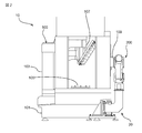
- FIG. 1 is a perspective view showing a robot system including the robot traveling device according to the first embodiment.
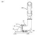
- FIG. 2 is a side view of the robot system of FIG.
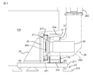
- FIG. 3 is an enlarged view of a portion of the robot traveling device of FIG. 2 to be installed on the floor surface.
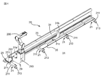
- FIG. 4 is a front perspective view showing the robot traveling device according to the first embodiment.
- FIG. 5 is a side view showing the robot traveling device of FIG.
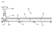
- FIG. 6 is a front view showing the robot traveling device of FIG.
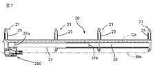
- FIG. 7 is a plan view showing the robot traveling device of FIG.
- FIG. 8 is a diagram supplementing the description of the effect of the robot traveling device of FIG.
- FIG. 9 is a side view showing the robot traveling device according to the second embodiment.
- FIG. 1 is a perspective view showing a robot system including the robot traveling device according to the first embodiment.
- FIG. 2 is a side view of the robot system of FIG.
- FIG. 3 is an enlarged view of a portion of the robot traveling
- FIG. 10 is a plan view of the robot traveling device of FIG.
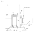
- FIG. 11 is an enlarged view of a portion of the robot traveling device of FIG. 9 to be installed on the floor surface.
- FIG. 12 is a side view showing the robot traveling device according to the third embodiment.
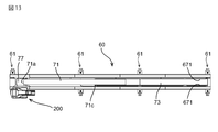
- FIG. 13 is a plan view of the robot traveling device of FIG.
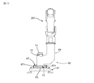
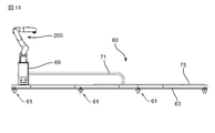
- FIG. 14 is a front view of the robot traveling device of FIG.
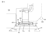
- FIG. 15 is an enlarged view of a portion of the robot traveling device of FIG. 12 to be installed on the floor surface.
- FIG. 16 is a side view showing the robot traveling device according to the fourth embodiment.
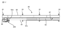
- FIG. 17 is a plan view of the robot traveling device of FIG.
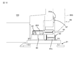
- FIG. 18 is an enlarged view of a portion of the robot traveling device of FIG. 16 to be installed on the floor surface.
- FIG. 2 and FIG. 3 show a robot system 10 including the robot traveling device 20 according to the first embodiment.
- 1 is a perspective view
- FIG. 2 is a side view
- FIG. 3 is an enlarged view of a portion of the robot traveling device 20 of FIG. 2 to be installed on the floor surface.
- the robot system 10 includes a machine tool 100, a robot 200 for attaching / detaching a work to / from the machine tool 100, and a robot traveling device 20 for running the robot 200 between the work place and the machine tool 100.
- the machine tool 100 is used to prepare a workpiece which is a molded part such as a molding machine or a machining center, or to connect a molded part to a supplied workpiece or perform machining. It is a device that performs the processing of.
- the machine tool 100 has a base 101 installed on the floor surface and a machine tool main body 103 mounted on the base 101. Inside the machine tool main body 103, a table 105 on which a work is installed and a spindle 107 provided with a jig for holding a machining tool are arranged.
- a slide door 109 for accessing the inside of the machine tool main body 103 is provided on the front surface of the machine tool main body 103. The slide door 109 is also used by a worker to access the inside of the machine tool 100 during maintenance work or the like.
- a space is formed between the machine tool body 103 and the floor surface.
- the front surface of the machine tool main body 103 provided with the slide door 109 projects outward with respect to the front surface of the base 101. That is, a space (dent) of a line extending in the left-right direction is formed in the lower part of the front surface of the machine tool 100.
- the robot traveling device 20 is installed in a recess at the lower part of the front surface of the machine tool 100 so that the robot 2000 can travel at a position close to the slide door 109 on the front surface of the machine tool 100. It is composed.
- FIG. 5 is a side view
- FIG. 6 is a front view
- FIG. 7 is a plan view.
- the robot traveling device 20 has a plurality of bases 21.
- the base 21 includes a base plate 211 and a plurality of legs 213 that support the base plate 211 so as to be able to move up and down with respect to the floor surface.
- the height of the leg portion 213 By adjusting the height of the leg portion 213, the height of the base 21 (the distance from the bottom surface (floor surface) of the leg portion 213 to the upper surface of the base plate 211) can be adjusted.
- the plurality of bases 21 are arranged discretely along the direction parallel to the moving axis of the robot 200.
- a long rectangular plate-shaped rail base 23 is installed on the plurality of bases 21.
- the toes of the worker can be inserted between the rail base 23 and the cable carrier 31 described later and the floor surface. It is in the point that I made it.
- the rail base 23 is not directly placed on the floor surface, but the rail base 23 is supported by a plurality of discretely arranged bases 21.
- the height of the base 21 is determined so that the toes of the safety shoes can be inserted between the rail base 23 and the cable carrier 31 and the floor surface.
- the height of the base 21 is preferably set to 50 to 100 mm, typically 70 mm, which is a height at which only the toes of safety shoes can be inserted.
- safety shoes It is recommended to wear safety shoes from the viewpoint of safety in a factory where the robot traveling device 20 is installed.
- the materials of safety shoes are determined by the Japanese Industrial Standards (JIS standard), etc., and safety shoes of the same size have almost the same outer shape.
- JIS standard Japanese Industrial Standards
- the worker is not a child, and the size of the worker's safety shoes does not differ significantly. Therefore, by determining the height of the base 21 as described above, the toes of the worker wearing the safety shoes can be almost certainly inserted.
- the toes of the safety shoes can be inserted between the floor surface and the rail base 23, the worker can approach the machine tool 100 even if the robot traveling device 20 is arranged adjacent to the machine tool 100. .. As a result, it is possible to suppress a decrease in workability of the maintenance work of the worker due to the installation of the robot traveling device 20 adjacent to the machine tool 100.
- the robot traveling device 20 by intentionally setting the height so that only the toes of the safety shoes can be inserted between the floor surface and the rail base 23 and the ankles of the safety shoes cannot be inserted, other parts constituting the robot traveling device 20. For example, it is possible to prevent the worker from excessively approaching the cable carrier 31 and the rail portion 27, and to prevent the worker from being injured, dirty, or damaged due to the worker's contact with these parts. Further, the safety of the worker can be ensured by preventing the worker from excessively approaching the machine tool 100. Further, since only the toes can be inserted, the risk of the worker falling is reduced and the deterioration of the operability of the worker's humorous movement can be suppressed as compared with the case where the ankle can be inserted, so that the safety is improved.
- the rail base 23 is attached at a right angle to the base plate 211 of the base 21 by a right-angled triangular attachment 25.
- the rail portion 27 is supported on the rail base 23.
- the rail portion 27 comprises a pair of rails 271.
- the pair of rails 271 are arranged parallel to each other along the direction perpendicular to the floor surface with respect to the rail base 23.
- the rail base 23 By vertically arranging the rail base 23 with respect to the floor surface in this way, it is possible to insert a tool such as a driver perpendicularly to the rail base 23 from the front of the machine tool 100. As a result, even if the robot traveling device 20 is installed in a place where the height is restricted, such as the lower part of the front surface of the machine tool 100, the rail portion 27 is replaced without pulling the machine tool 100 forward from the lower part of the front surface. And so on. This improves the workability of the maintenance work of the worker. Further, by arranging the rail base 23 vertically, it becomes difficult for dust such as chips and chips to enter the rail portion 27 as compared with the case where the rail base 23 is placed horizontally. The possibility of malfunctions can be reduced. Further, by arranging the rail base 23 vertically, the installation height may be increased, but the installation width can be narrowed, so that the robot traveling device 20 is installed in a place where the height is high but the depth is narrow. can do.
- the stand 29 is movably supported on the rail portion 27.
- the robot 200 is placed on the stand 29.
- the type of robot 200 used here is not particularly limited.
- a type of robot 200 such as a vertical articulated robot or a SCARA robot can be used.
- the stand 29 has a slider portion 291 and a stand body 293.
- the slider portion 291 is a quadrangular flat plate member and is slidably attached to the rail portion 27.
- the stand body 293 has an outer shape having a substantially L-shaped vertical cross section. Specifically, the stand body 293 is formed in a substantially L-shaped groove-like body having an open outer surface.
- the stand main body 293 has a connecting surface with the slider portion 291 at one end thereof, and has a mounting surface on which the robot 200 is mounted at the other end.
- the stand body 293 has a slider portion such that the base end side portion is parallel to the floor surface and the tip end side portion is perpendicular to the floor surface, and the robot mounting surface faces upward. It is attached to 291.
- the L-shaped stand 29 functions as a relay component that connects the position where the robot traveling device 20 is to be installed and the position where the robot 200 is desired to travel.
- the L-shaped stand 29 can offset the traveling axis Ma on which the robot 200 actually travels with respect to the central axis Ca of the rail portion 27 in the horizontal direction and the vertical direction.
- the place where the robot traveling device 20 is to be installed is the lower part of the front surface of the machine tool 100
- the position where the robot 200 is desired to travel is the slide door 109 on the front surface of the machine tool 100.
- the traveling axis of the robot 200 can be offset in the horizontal direction with respect to the rail central axis Ca, so that the robot 200 is directly above the rail portion 27. Since it does not move, it is possible to reduce the possibility that liquids such as chips and dripping water that have fallen from the work gripped by the robot 200 adhere to the rail portion 27. For example, dust accumulated on the rail portion 27 is collected on the slider portion. It is possible to reduce the risk of problems such as stopping the running of the robot 200 due to being entangled with 291.
- the height of the robot traveling device 20 can be suppressed.
- the height from the floor surface to the upper edge of the rail base 23 is suppressed to 500 mm or less.
- it can be installed even in a narrow place such as the lower part of the front surface of the machine tool 100.
- the base 21, the rail base 23, the rail portion 27, and the cable carrier 31 other than the stand 29 constituting the robot traveling device 20 are concentrated in the space below the front surface of the machine tool 100, the machine tool 100 is included in these components. The possibility of dust such as chips coming out of the machine and liquid adhering to it is also suppressed.
- the outer shape of the stand 29 is not limited to the L shape.
- the outer shape of the stand 29 may be curved in an arc shape, or may be bent in a staircase shape. If there is an obstacle between the position where the robot traveling device 20 is to be installed and the position where the robot 200 is desired to be traveled, the stand 29 can have various shapes to avoid the obstacle.
- a motor unit 35 having a motor that generates a driving force that drives the movement of the slider unit 291 and a speed reducer that reduces the rotation of the motor, a control device (not shown) that controls the motor, and the like. It is assembled. Since the outer surface of the stand body 293 is open, workers can easily access these devices. This contributes to improving the workability of maintenance work by workers.
- the cable carrier 31 is composed of a plurality of hollow frames that are pivotally connected to each other. The cable is passed through this hollow part and protected.
- the total length of the cable carrier 31 is longer than the total length of the rail portion 27, and the cable carrier 31 is arranged so as to vertically straddle the base end portion parallel to the floor surface of the stand main body 293 by folding back the intermediate portion in a U shape.
- One end 31a of the cable carrier 31 is fixed to the stand body 293 via a bracket 37.
- the position where the end portion 31a of the cable carrier 31 is fixed is a position close to the rail portion 27 on the upper surface of the base end portion parallel to the floor surface of the stand body 293.
- the other end 31c of the cable carrier 31 is fixed to a support plate 33 laid horizontally on the upper surface of the plurality of bases 21.
- the position where the other end 31c of the cable carrier 31 is fixed is near the center of the length of the robot traveling device 20 (rail portion).
- the support plate 33 prevents the cable carrier portion from the end portion 31c of the cable carrier 31 to the bent portion 31b from hanging downward.
- the end 31c of the cable carrier 31 may be fixed directly to the upper surface of the base 21 near the center of the plurality of bases 21 or indirectly via a bracket.
- the cable extending from the external system control device or the external power supply device is inserted into the cable carrier 31 from the end 31c of the cable carrier 31 fixed near the center of the length of the robot traveling device 20, and is inside the cable carrier 31. Is pulled out from the end 31a of the cable carrier 31 fixed to the stand 29.
- the cable routed to the stand 29 by the cable carrier 31 is connected to the robot 200 mounted on the stand 29 and the control device assembled inside the stand 29.
- the robot traveling device 20 and the robot 200 can be operated stably.
- the cable carrier 31 By arranging the cable carrier 31 between the robot 200 and the rail portion 27, it is possible to reduce the possibility that dust such as chips from the work gripped by the robot 200 adheres to the rail portion. Further, when the robot traveling device 20 is installed on the floor surface below the overhanging portion of the machine tool 100, the rail portion 27 can be arranged further back, so that the above possibility is further reduced and the work is performed. It is possible to reduce the possibility that the liquid such as water used in the machine 100 adheres to the rail portion 27, the cable carrier 31, and the like. Further, since the cable carrier 31 is arranged on the surface side of the rail base 23, the operator can easily access the cable carrier 31 with the robot traveling device 20 installed at the lower part of the front surface of the machine tool. Since the cable is one of the parts that require frequent maintenance, the workability of maintenance is improved by arranging the cable carrier 31 as described above.
- a gap is formed between the floor surface and the rail base 23 into which the toes of the safety shoes enter.
- the operator can approach the slide door 109 of the machine tool 100 as compared with the case where the gap is not formed.
- the installation height of the robot traveling device 20 can be suppressed, and the position where the rail portion 27 is installed is set in the horizontal direction and the vertical direction with respect to the position where the robot 200 is traveled. Can be offset.
- the robot traveling device 20 can be installed in a narrow space below the front surface of the machine tool 100, and the robot 200 can be traveled at a position close to the slide door 109 protruding from the front surface of the machine tool 100. Since the main components of the robot traveling device 20 are integrated in the lower part of the front surface of the machine tool 100 and only the stand 29 protrudes from the front surface of the machine tool 100, the stand 29 should be retracted from the front surface of the machine tool 100. Then, the operator can approach the slide door 109 of the machine tool 100.
- the robot traveling device 20 can be installed in a narrow space below the front surface of the machine tool 100, and the worker W can be installed on the machine tool 100 as in the case where the robot traveling device 20 is not installed. Can approach (see FIGS. 8 (a) and 8 (b)). This means that the robot traveling device is closer to the machine tool 100 by a distance L equivalent to the width of the conventional robot traveling device as compared with the case where the conventional robot traveling device is installed (see FIG. 8C). This makes it possible to perform maintenance work on the machine tool 100 at a standing position substantially the same as when the robot traveling device 20 is not installed, and it is possible to suppress a decrease in workability due to the installation of the robot traveling device 20.
- the cable carrier 31 is installed on the surface side of the rail base 23, but the position where the cable carrier 31 is installed is not limited to this.
- the robot traveling device 40 according to the second embodiment is a device in which the cable carrier 31 arranged on the front surface side of the rail base 23 in the robot traveling device 20 according to the first embodiment is arranged on the back surface side of the rail base 23. be.
- the robot traveling device 40 according to the second embodiment will be described with reference to FIGS. 9, 10 and 11.
- the robot traveling device 40 has a base 41, a rail base 43, a rail portion 47, a stand 49, a cable carrier 51, and a support plate 53.
- the base 41, rail base 43, rail portion 47 and stand 49 of the robot traveling device 40 according to the second embodiment are the base 21, rail base 23, rail portion 27 and stand 29 of the robot traveling device 20 according to the first embodiment. Since it is configured in the same manner as above, the description thereof will be omitted.
- the cable carrier 51 is arranged on the back surface side of the rail base 23.
- One end 51a of the cable carrier 51 is fixed to the stand body 493 via a bracket.
- the height from the floor surface to the upper surface of the end portion 51a of the cable carrier 51 is equal to or slightly lower than the height from the floor surface to the upper end of the rail base 43. ..
- the other end 51c of the cable carrier 51 is fixed to a support plate 53 laid horizontally on the upper surface of the plurality of bases 41.
- the position where the other end 51c of the cable carrier 51 is fixed is near the center of the length of the robot traveling device 40 (rail portion 47).
- the robot traveling device 40 according to the second embodiment since the cable carrier 51 is arranged on the back surface side of the rail base 43, the robot according to the first embodiment has the cable carrier 31 arranged on the front surface side of the rail base 23. Although the workability of the cable maintenance work is lower than that of the traveling device 20, it is possible to obtain the same effects as the robot traveling device 20 according to the first embodiment with respect to other effects.
- the rail bases 23 and 43 are vertically arranged, but the rail bases 23 and 43 may be horizontally arranged.
- the robot traveling device 60 according to the third embodiment is configured by arranging the rail base 63 horizontally.
- the robot traveling device 60 according to the third embodiment will be described with reference to FIGS. 12, 13, 14, and 15.
- the robot traveling device 60 has a plurality of bases 61.
- a long rectangular plate-shaped rail base 63 is horizontally placed on the plurality of bases 61 in a horizontal direction with respect to the floor surface.
- a rail portion 67 is supported on the rail base 63.
- the rail portion 67 has a pair of rails 671.
- the pair of rails 671 are arranged side by side in a direction parallel to the floor surface.
- a stand 69 is movably supported on the rail portion 67.
- the robot 200 is placed on the stand 69.
- the stand 69 has a slider portion 691 and a stand body 693.
- the slider portion 691 is a quadrangular flat plate member and is slidably attached to the rail portion 67.
- the stand body 693 has a substantially L-shaped outer shape.
- the stand body 693 is attached to the slider portion 691 so that the base end portion is parallel to the floor surface and the tip end portion is perpendicular to the floor surface.
- the side surface of the stand body 693 on the base end side is attached to the slider portion 691.
- the cable carrier 71 is arranged above the rail base 63 so as to straddle the stand body 793 and the slider portion 691 vertically.
- One end 71a of the cable carrier 71 is fixed to the stand body 793 via the bracket 77.
- the other end 71c of the cable carrier 71 is fixed to a support plate 73 arranged below the pair of rails 671.
- the position where the other end 71c of the cable carrier 71 is fixed is near the center of the length of the robot traveling device 60 (rail portion 67) between the pair of rails 671.
- the robot traveling device 60 according to the third embodiment has the rail base 63 horizontally arranged, it is compared with the robot traveling devices 20 and 40 according to the first and second embodiments in which the rail bases 23 and 43 are vertically arranged. , Dust, chips, dust, etc. tend to collect on the rail portion 67, which may increase the maintenance frequency. Further, at the time of maintenance such as rail replacement, the robot traveling device 60 must be pulled out from the space at the lower part of the front surface of the machine tool 100, which may reduce the workability of the maintenance work. However, since the installation height can be kept low by arranging the rail base 63 horizontally, the robot traveling device 60 can be arranged in a place having a depth but a low height. Regarding the effects other than the above, the same effects as those of the robot traveling devices 20 and 40 according to the first and second embodiments can be obtained.
- the cable carrier 71 is installed above the rail base 63, but the position where the cable carrier 71 is installed is not limited to this.
- the cable carrier 71 arranged above the rail base 63 in the robot traveling device 60 according to the third embodiment is arranged adjacent to the rail base 63. ..
- the robot traveling device 80 according to the fourth embodiment will be described with reference to FIGS. 16, 17, and 18.
- the robot traveling device 80 has a plurality of bases 81.
- a long rectangular plate-shaped rail base 83 is horizontally placed on the plurality of bases 81 in a horizontal direction with respect to the floor surface.
- a rail portion 87 is supported on the rail base 83.
- a stand 89 is movably supported on the rail portion 87. The robot 200 is placed on the stand 89.
- the stand 89 has a slider portion 891 and a stand body 893.
- the slider portion 891 is a quadrangular flat plate member and is slidably attached to the rail portion 87.
- the stand body 893 has a substantially L-shaped outer shape. The stand body 893 is attached to the slider portion 891 so that the base end portion is parallel to the floor surface and the tip end portion is perpendicular to the floor surface.
- the cable carrier 91 is arranged at a position adjacent to the rail base 83 so as to straddle the base end portion of the stand body 893 up and down.
- One end 91a of the cable carrier 91 is fixed to the stand body 893 via the bracket 97.
- the position where the end portion 91a of the cable carrier 91 is fixed is a position slightly above the base end portion of the stand body 893.
- the other end 91c of the cable carrier 91 is fixed to a support plate 93 laid horizontally on the upper surface of the plurality of bases 81.
- the position where the other end 91c of the cable carrier 91 is fixed is near the center of the length of the robot traveling device 80 (rail portion 87).
- the robot traveling device 80 according to the fourth embodiment relates to the third embodiment in which the cable carrier 91 is arranged above the rail portion 87 because the cable carrier 91 is arranged between the rail portion 87 and the robot 200.
- the amount of dust generated from the machine tool 100 accumulated on the rail portion 87 can be reduced, and the installation width can be increased, but the installation height can be further suppressed. Therefore, the robot traveling device 80 can be arranged in a place having a depth but a low height. Further, with respect to the effects other than the above, the same effects as those of the robot traveling device 60 according to the third embodiment can be obtained.
- Robot system 20 ... Robot traveling device, 100 ... Machine tool, 101 ... Base, 103 ... Machine tool body, 105 ... Table, 107 ... Spindle, 109 ... Sliding door.
Landscapes
- Engineering & Computer Science (AREA)
- Mechanical Engineering (AREA)
- Robotics (AREA)
- Manipulator (AREA)
Abstract
Description
図1、図2及び図3は、第1実施形態に係るロボット走行装置20を備えるロボットシステム10を示している。図1は斜視図、図2は側面図、図3は、図2のロボット走行装置20の床面に設置する部分の拡大図である。ロボットシステム10は、工作機械100と、工作機械100へのワークの着脱を行うロボット200と、ワーク置き場と工作機械100との間でロボット200を走行させるためのロボット走行装置20と、を有する。
図4、図5、図6及び図7は、第1実施形態に係るロボット走行装置20を示している。図4は斜視図、図5は側面図、図6は正面図、図7は平面図である。
すなわち、L字形のスタンド29は、ロボット走行装置20を設置したい位置とロボット200を走行させたい位置とを結ぶ中継部品として機能する。例えば、図7に示すように、L字形のスタンド29は、レール部27の中心軸Caに対してロボット200が実際に走行する走行軸Maを水平方向と鉛直方向とにオフセットさせることができる。それにより、図1、図2に示すように、ロボット走行装置20を設置したい場所が工作機械100の前面下部であって、ロボット200を走行させたい位置が工作機械100の前面のスライド扉109の前方であるような設置要求があっても、L字形のスタンド29を用いることによって、対応することができる。L字形のスタンド29を使用することで、図7に示すように、レール中心軸Caに対してロボット200の走行軸を水平方向にオフセットすることができるため、レール部27の直上をロボット200が移動しないため、ロボット200が把持するワークから落下した切り屑や垂れた水などの液体がレール部27に付着する可能性を低減することができ、例えば、レール部27に堆積したゴミがスライダ部291に絡んでしまって、ロボット200の走行を停止させてしまうなどの不具合が発生するリスクを抑えられる。
第1実施形態に係るロボット走行装置20は、ケーブルキャリア31をレールベース23の表面側に設置していたが、ケーブルキャリア31が設置される位置はこれに限定されない。第2実施形態に係るロボット走行装置40は、第1実施形態に係るロボット走行装置20においてレールベース23の表面側に配置されていたケーブルキャリア31を、レールベース23の裏面側に配置したものである。以下、図9、図10及び図11を参照して第2実施形態に係るロボット走行装置40を説明する。
第1、第2実施形態に係るロボット走行装置20、40は、レールベース23,43を縦置きしていたが、レールベース23,43は横置きしてもよい。第3実施形態に係るロボット走行装置60は、レールベース63を横置きにして構成したものである。以下、図12、図13、図14及び図15を参照して第3実施形態に係るロボット走行装置60を説明する。
第3実施形態に係るロボット走行装置20は、ケーブルキャリア71をレールベース63の上方に設置していたが、ケーブルキャリア71が設置される位置はこれに限定されない。第4実施形態に係るロボット走行装置80は、第3実施形態に係るロボット走行装置60においてレールベース63の上方に配置されていたケーブルキャリア71を、レールベース63に隣接して配置したものである。以下、図16、図17及び図18を参照して第4実施形態に係るロボット走行装置80を説明する。
Claims (10)
- 床面に配置されるロボット走行装置において、
前記床面に離散的に設置される複数の土台と、
前記複数の土台上に設置されるレールベースと、
前記レールベースに支持されるレール部と、
前記レール部に移動自在に支持され、ロボットが載置されるスタンド部と、
前記ロボットのケーブルを保護する柔軟性を有するケーブルキャリアとを具備し、
前記土台の高さは、前記レールベース及び前記ケーブルキャリアと前記床面との間に50乃至100mmの間隙が設けられるように決定されている、ロボット走行装置。 - 前記レール部は、一対のレールを有し、
前記一対のレールは前記床面に対して垂直な方向に沿って並設される、請求項1に記載のロボット走行装置。 - 前記床面から前記レール部の上縁までの高さは500mm以下である、請求項2記載のロボット走行装置。
- 前記ケーブルキャリアは、前記レールベースを挟んで前記一対のレールと同側に配置される、請求項2記載のロボット走行装置。
- 前記ケーブルキャリアは、前記レールベースを挟んで前記一対のレールと反対側に配置される、請求項2記載のロボット走行装置。
- 前記レール部は、一対のレールを有し、
前記一対のレールは前記床面に対して水平な方向に沿って並設される、請求項1に記載のロボット走行装置。 - 前記ケーブルキャリアは、前記レールベースの上方に配置される、請求項6記載のロボット走行装置。
- 前記スタンド部は、縦断面L字外形を有する、請求項1乃至7のいずれか一項に記載のロボット走行装置。
- 床面に配置されるロボット走行装置において、
前記床面に離散的に設置される複数の土台と、
前記複数の土台上に設置されるレールベースと、
前記レールベースに支持されるレール部と、
前記レール部に移動自在に支持され、ロボットが載置されるスタンド部と、
を具備し、
前記レール部は、一対のレールを有し、
前記一対のレールは前記床面に対して垂直な方向に沿って並設され、
前記スタンド部は縦断面L字外形を有する、ロボット走行装置。 - 工作機械と、
前記工作機械に対してワークを着脱するロボットを移動自在に支持するロボット走行装置と、を具備し、
前記工作機械は、
床面に設置される基台と、
前記基台上に載置される工作機械本体とを有し、
前記ロボット走行装置は、
前記床面に離散的に設置される複数の土台と、
前記複数の土台上に設置されるレールベースと、
前記レールベースに支持されるレール部と、
前記レール部に移動自在に支持され、前記ロボットが載置されるスタンド部と、
前記ロボットのケーブルを保護する柔軟性を有するケーブルキャリアとを有し、
前記工作機械本体と前記床面との間のスペースに、前記土台とともに前記レールベース、前記レール部及び前記ケーブルキャリアが集約的に配置され、
前記スタンド部は、前記ロボットを前記工作機械本体の前面に配置するために前記レール部から前記工作機械本体の前面にわたって屈曲した縦断面L字外形を有する、ロボットシステム。
Priority Applications (4)
| Application Number | Priority Date | Filing Date | Title |
|---|---|---|---|
| CN202180019801.0A CN115243836B (zh) | 2020-03-10 | 2021-03-04 | 机器人行驶装置以及机器人系统 |
| US17/908,169 US12548993B2 (en) | 2020-03-10 | 2021-03-04 | Robot traveling device and robot system |
| JP2022506004A JP7448635B2 (ja) | 2020-03-10 | 2021-03-04 | ロボット走行装置及びロボットシステム |
| DE112021001512.5T DE112021001512T5 (de) | 2020-03-10 | 2021-03-04 | Roboterfahrvorrichtung und Robotersystem |
Applications Claiming Priority (2)
| Application Number | Priority Date | Filing Date | Title |
|---|---|---|---|
| JP2020-041363 | 2020-03-10 | ||
| JP2020041363 | 2020-03-10 |
Publications (1)
| Publication Number | Publication Date |
|---|---|
| WO2021182300A1 true WO2021182300A1 (ja) | 2021-09-16 |
Family
ID=77672079
Family Applications (1)
| Application Number | Title | Priority Date | Filing Date |
|---|---|---|---|
| PCT/JP2021/008468 Ceased WO2021182300A1 (ja) | 2020-03-10 | 2021-03-04 | ロボット走行装置及びロボットシステム |
Country Status (5)
| Country | Link |
|---|---|
| US (1) | US12548993B2 (ja) |
| JP (1) | JP7448635B2 (ja) |
| CN (1) | CN115243836B (ja) |
| DE (1) | DE112021001512T5 (ja) |
| WO (1) | WO2021182300A1 (ja) |
Citations (8)
| Publication number | Priority date | Publication date | Assignee | Title |
|---|---|---|---|---|
| JPH05317762A (ja) * | 1992-05-15 | 1993-12-03 | Tokico Ltd | 塗装用ロボット装置 |
| JP2005096018A (ja) * | 2003-09-24 | 2005-04-14 | Toyota Motor Corp | ロボット走行装置 |
| JP2009184024A (ja) * | 2008-02-01 | 2009-08-20 | Ikd:Kk | 走行装置 |
| JP2012000681A (ja) * | 2010-06-14 | 2012-01-05 | Yaskawa Electric Corp | ロボット |
| WO2016103304A1 (ja) * | 2014-12-26 | 2016-06-30 | 川崎重工業株式会社 | 生産システム |
| JP2018167376A (ja) * | 2017-03-30 | 2018-11-01 | 株式会社デンソーウェーブ | レール着脱機構、及びロボットシステム |
| JP2019005890A (ja) * | 2017-01-27 | 2019-01-17 | ザ・ボーイング・カンパニーThe Boeing Company | ベルト駆動デュアルロボットガントリ |
| JP2019063930A (ja) * | 2017-09-29 | 2019-04-25 | アイシン・エィ・ダブリュ株式会社 | ワーク搬送装置 |
Family Cites Families (10)
| Publication number | Priority date | Publication date | Assignee | Title |
|---|---|---|---|---|
| GB2168934B (en) * | 1984-12-19 | 1988-07-27 | Honda Motor Co Ltd | Method and apparatus for mounting parts to both sides of a main body |
| CA1312349C (en) * | 1986-11-08 | 1993-01-05 | Genzo Fuse | Robot apparatus |
| JP2768858B2 (ja) * | 1991-11-22 | 1998-06-25 | 日本原子力研究所 | トカマク型核融合炉の遠隔保全装置 |
| FI96102C (fi) * | 1994-10-03 | 1996-05-10 | Pulmek Oy | Järjestelmä robotin siirtämiseksi |
| JPH08276385A (ja) * | 1995-04-06 | 1996-10-22 | Matsui Seisakusho:Kk | 壁掛式水平移動装置 |
| JP2004114258A (ja) * | 2002-09-27 | 2004-04-15 | Mori Seiki Hitech Co Ltd | 工作物搬送装置を備えた工作機械 |
| JP4217125B2 (ja) * | 2003-07-30 | 2009-01-28 | トヨタ自動車株式会社 | 生産システム |
| JP4612087B2 (ja) | 2008-10-09 | 2011-01-12 | ファナック株式会社 | ロボットにより工作機械へワークの着脱を行うロボットシステム |
| DE102017007962A1 (de) * | 2017-08-24 | 2019-02-28 | Deckel Maho Seebach Gmbh | Werkzeugmaschine |
| JP2020192656A (ja) * | 2019-05-30 | 2020-12-03 | 株式会社Aqua・J | ワーク搬送装置 |
-
2021
- 2021-03-04 WO PCT/JP2021/008468 patent/WO2021182300A1/ja not_active Ceased
- 2021-03-04 US US17/908,169 patent/US12548993B2/en active Active
- 2021-03-04 JP JP2022506004A patent/JP7448635B2/ja active Active
- 2021-03-04 DE DE112021001512.5T patent/DE112021001512T5/de active Pending
- 2021-03-04 CN CN202180019801.0A patent/CN115243836B/zh active Active
Patent Citations (8)
| Publication number | Priority date | Publication date | Assignee | Title |
|---|---|---|---|---|
| JPH05317762A (ja) * | 1992-05-15 | 1993-12-03 | Tokico Ltd | 塗装用ロボット装置 |
| JP2005096018A (ja) * | 2003-09-24 | 2005-04-14 | Toyota Motor Corp | ロボット走行装置 |
| JP2009184024A (ja) * | 2008-02-01 | 2009-08-20 | Ikd:Kk | 走行装置 |
| JP2012000681A (ja) * | 2010-06-14 | 2012-01-05 | Yaskawa Electric Corp | ロボット |
| WO2016103304A1 (ja) * | 2014-12-26 | 2016-06-30 | 川崎重工業株式会社 | 生産システム |
| JP2019005890A (ja) * | 2017-01-27 | 2019-01-17 | ザ・ボーイング・カンパニーThe Boeing Company | ベルト駆動デュアルロボットガントリ |
| JP2018167376A (ja) * | 2017-03-30 | 2018-11-01 | 株式会社デンソーウェーブ | レール着脱機構、及びロボットシステム |
| JP2019063930A (ja) * | 2017-09-29 | 2019-04-25 | アイシン・エィ・ダブリュ株式会社 | ワーク搬送装置 |
Also Published As
| Publication number | Publication date |
|---|---|
| JPWO2021182300A1 (ja) | 2021-09-16 |
| DE112021001512T5 (de) | 2023-01-05 |
| CN115243836B (zh) | 2025-08-26 |
| CN115243836A (zh) | 2022-10-25 |
| US20230121702A1 (en) | 2023-04-20 |
| JP7448635B2 (ja) | 2024-03-12 |
| US12548993B2 (en) | 2026-02-10 |
Similar Documents
| Publication | Publication Date | Title |
|---|---|---|
| US8282333B2 (en) | Workpiece transfer robot system | |
| AU2008283289B9 (en) | Work conveying apparatus | |
| US7959386B2 (en) | Splash guard of machine tool | |
| US8272296B2 (en) | Screw fastener | |
| US20140319746A1 (en) | Machine tool | |
| US20040037663A1 (en) | Device for the translatory positioning of a platform | |
| US20240091817A1 (en) | Device for cleaning support bars of a first workpiece support of a first laser cutting machine | |
| US20150336472A1 (en) | Transport facility and automated warehouse | |
| CN107000135B (zh) | 用于激光切割机械的桥接部 | |
| CN104411452B (zh) | 机床 | |
| CN108136554B (zh) | 加工中心 | |
| WO2021182300A1 (ja) | ロボット走行装置及びロボットシステム | |
| JP3725625B2 (ja) | 工作機械 | |
| CN107263117A (zh) | 加工大型部件的磨铣一体化复合机床 | |
| JP5682491B2 (ja) | 組立作業用コンベア装置 | |
| KR102748374B1 (ko) | 이송장치 | |
| CN106425180A (zh) | 车身焊装用防飞溅结构 | |
| EP2529880B1 (en) | Machine tool | |
| JPH11123675A (ja) | ロボットの垂直軸上下機構 | |
| JPWO2024038671A5 (ja) | ||
| US2557850A (en) | Way guard | |
| KR101989918B1 (ko) | 자체 가이드 기능을 갖는 공작기계 슬라이드 커버용 가이드 레일 | |
| KR101867910B1 (ko) | 조립부품용박스 자동공급시스템 | |
| JPH04217490A (ja) | 産業用ロボットの安全装置 | |
| WO2022234620A1 (ja) | 工作機械 |
Legal Events
| Date | Code | Title | Description |
|---|---|---|---|
| 121 | Ep: the epo has been informed by wipo that ep was designated in this application |
Ref document number: 21767622 Country of ref document: EP Kind code of ref document: A1 |
|
| ENP | Entry into the national phase |
Ref document number: 2022506004 Country of ref document: JP Kind code of ref document: A |
|
| 122 | Ep: pct application non-entry in european phase |
Ref document number: 21767622 Country of ref document: EP Kind code of ref document: A1 |
|
| WWG | Wipo information: grant in national office |
Ref document number: 202180019801.0 Country of ref document: CN |
|
| WWG | Wipo information: grant in national office |
Ref document number: 17908169 Country of ref document: US |