WO2021182229A1 - 画像生成装置およびプログラム、学習装置およびプログラム、並びに画像処理装置およびプログラム - Google Patents
画像生成装置およびプログラム、学習装置およびプログラム、並びに画像処理装置およびプログラム Download PDFInfo
- Publication number
- WO2021182229A1 WO2021182229A1 PCT/JP2021/008162 JP2021008162W WO2021182229A1 WO 2021182229 A1 WO2021182229 A1 WO 2021182229A1 JP 2021008162 W JP2021008162 W JP 2021008162W WO 2021182229 A1 WO2021182229 A1 WO 2021182229A1
- Authority
- WO
- WIPO (PCT)
- Prior art keywords
- image
- lesion
- radiation
- processor
- teacher data
- Prior art date
- Legal status (The legal status is an assumption and is not a legal conclusion. Google has not performed a legal analysis and makes no representation as to the accuracy of the status listed.)
- Ceased
Links
Images


Classifications
-
- G—PHYSICS
- G06—COMPUTING OR CALCULATING; COUNTING
- G06T—IMAGE DATA PROCESSING OR GENERATION, IN GENERAL
- G06T11/00—2D [Two Dimensional] image generation
- G06T11/003—Reconstruction from projections, e.g. tomography
-
- G—PHYSICS
- G06—COMPUTING OR CALCULATING; COUNTING
- G06T—IMAGE DATA PROCESSING OR GENERATION, IN GENERAL
- G06T11/00—2D [Two Dimensional] image generation
- G06T11/003—Reconstruction from projections, e.g. tomography
- G06T11/006—Inverse problem, transformation from projection-space into object-space, e.g. transform methods, back-projection, algebraic methods
-
- A—HUMAN NECESSITIES
- A61—MEDICAL OR VETERINARY SCIENCE; HYGIENE
- A61B—DIAGNOSIS; SURGERY; IDENTIFICATION
- A61B6/00—Apparatus or devices for radiation diagnosis; Apparatus or devices for radiation diagnosis combined with radiation therapy equipment
-
- A—HUMAN NECESSITIES
- A61—MEDICAL OR VETERINARY SCIENCE; HYGIENE
- A61B—DIAGNOSIS; SURGERY; IDENTIFICATION
- A61B6/00—Apparatus or devices for radiation diagnosis; Apparatus or devices for radiation diagnosis combined with radiation therapy equipment
- A61B6/02—Arrangements for diagnosis sequentially in different planes; Stereoscopic radiation diagnosis
-
- A—HUMAN NECESSITIES
- A61—MEDICAL OR VETERINARY SCIENCE; HYGIENE
- A61B—DIAGNOSIS; SURGERY; IDENTIFICATION
- A61B6/00—Apparatus or devices for radiation diagnosis; Apparatus or devices for radiation diagnosis combined with radiation therapy equipment
- A61B6/50—Apparatus or devices for radiation diagnosis; Apparatus or devices for radiation diagnosis combined with radiation therapy equipment specially adapted for specific body parts; specially adapted for specific clinical applications
- A61B6/502—Apparatus or devices for radiation diagnosis; Apparatus or devices for radiation diagnosis combined with radiation therapy equipment specially adapted for specific body parts; specially adapted for specific clinical applications for diagnosis of breast, i.e. mammography
-
- A—HUMAN NECESSITIES
- A61—MEDICAL OR VETERINARY SCIENCE; HYGIENE
- A61B—DIAGNOSIS; SURGERY; IDENTIFICATION
- A61B6/00—Apparatus or devices for radiation diagnosis; Apparatus or devices for radiation diagnosis combined with radiation therapy equipment
- A61B6/52—Devices using data or image processing specially adapted for radiation diagnosis
- A61B6/5211—Devices using data or image processing specially adapted for radiation diagnosis involving processing of medical diagnostic data
- A61B6/5217—Devices using data or image processing specially adapted for radiation diagnosis involving processing of medical diagnostic data extracting a diagnostic or physiological parameter from medical diagnostic data
-
- G—PHYSICS
- G06—COMPUTING OR CALCULATING; COUNTING
- G06N—COMPUTING ARRANGEMENTS BASED ON SPECIFIC COMPUTATIONAL MODELS
- G06N3/00—Computing arrangements based on biological models
- G06N3/02—Neural networks
- G06N3/08—Learning methods
- G06N3/09—Supervised learning
-
- G—PHYSICS
- G06—COMPUTING OR CALCULATING; COUNTING
- G06T—IMAGE DATA PROCESSING OR GENERATION, IN GENERAL
- G06T7/00—Image analysis
- G06T7/0002—Inspection of images, e.g. flaw detection
- G06T7/0012—Biomedical image inspection
-
- G—PHYSICS
- G06—COMPUTING OR CALCULATING; COUNTING
- G06T—IMAGE DATA PROCESSING OR GENERATION, IN GENERAL
- G06T7/00—Image analysis
- G06T7/30—Determination of transform parameters for the alignment of images, i.e. image registration
- G06T7/33—Determination of transform parameters for the alignment of images, i.e. image registration using feature-based methods
- G06T7/344—Determination of transform parameters for the alignment of images, i.e. image registration using feature-based methods involving models
-
- A—HUMAN NECESSITIES
- A61—MEDICAL OR VETERINARY SCIENCE; HYGIENE
- A61B—DIAGNOSIS; SURGERY; IDENTIFICATION
- A61B6/00—Apparatus or devices for radiation diagnosis; Apparatus or devices for radiation diagnosis combined with radiation therapy equipment
- A61B6/04—Positioning of patients; Tiltable beds or the like
- A61B6/0407—Supports, e.g. tables or beds, for the body or parts of the body
- A61B6/0414—Supports, e.g. tables or beds, for the body or parts of the body with compression means
-
- G—PHYSICS
- G06—COMPUTING OR CALCULATING; COUNTING
- G06N—COMPUTING ARRANGEMENTS BASED ON SPECIFIC COMPUTATIONAL MODELS
- G06N3/00—Computing arrangements based on biological models
- G06N3/02—Neural networks
- G06N3/04—Architecture, e.g. interconnection topology
- G06N3/044—Recurrent networks, e.g. Hopfield networks
-
- G—PHYSICS
- G06—COMPUTING OR CALCULATING; COUNTING
- G06N—COMPUTING ARRANGEMENTS BASED ON SPECIFIC COMPUTATIONAL MODELS
- G06N3/00—Computing arrangements based on biological models
- G06N3/02—Neural networks
- G06N3/04—Architecture, e.g. interconnection topology
- G06N3/0464—Convolutional networks [CNN, ConvNet]
-
- G—PHYSICS
- G06—COMPUTING OR CALCULATING; COUNTING
- G06N—COMPUTING ARRANGEMENTS BASED ON SPECIFIC COMPUTATIONAL MODELS
- G06N3/00—Computing arrangements based on biological models
- G06N3/02—Neural networks
- G06N3/04—Architecture, e.g. interconnection topology
- G06N3/047—Probabilistic or stochastic networks
-
- G—PHYSICS
- G06—COMPUTING OR CALCULATING; COUNTING
- G06T—IMAGE DATA PROCESSING OR GENERATION, IN GENERAL
- G06T2207/00—Indexing scheme for image analysis or image enhancement
- G06T2207/10—Image acquisition modality
- G06T2207/10116—X-ray image
- G06T2207/10124—Digitally reconstructed radiograph [DRR]
-
- G—PHYSICS
- G06—COMPUTING OR CALCULATING; COUNTING
- G06T—IMAGE DATA PROCESSING OR GENERATION, IN GENERAL
- G06T2207/00—Indexing scheme for image analysis or image enhancement
- G06T2207/20—Special algorithmic details
- G06T2207/20081—Training; Learning
-
- G—PHYSICS
- G06—COMPUTING OR CALCULATING; COUNTING
- G06T—IMAGE DATA PROCESSING OR GENERATION, IN GENERAL
- G06T2207/00—Indexing scheme for image analysis or image enhancement
- G06T2207/30—Subject of image; Context of image processing
- G06T2207/30004—Biomedical image processing
- G06T2207/30096—Tumor; Lesion
-
- G—PHYSICS
- G06—COMPUTING OR CALCULATING; COUNTING
- G06T—IMAGE DATA PROCESSING OR GENERATION, IN GENERAL
- G06T2211/00—Image generation
- G06T2211/40—Computed tomography
- G06T2211/436—Limited angle
-
- G—PHYSICS
- G06—COMPUTING OR CALCULATING; COUNTING
- G06T—IMAGE DATA PROCESSING OR GENERATION, IN GENERAL
- G06T2211/00—Image generation
- G06T2211/40—Computed tomography
- G06T2211/441—AI-based methods, deep learning or artificial neural networks
Definitions
- the present disclosure relates to an image generator and a program, a learning device and a program, and an image processing device and a program.
- mammography radiographic imaging device
- Tomosynthesis imaging has been proposed to produce.
- tomosynthesis imaging multiple source locations can be moved in parallel with the radiation detector or in a circular or elliptical arc, depending on the characteristics of the imaging device and the required tomographic image.
- a back projection method such as a simple back projection method or a filter back projection method, or a sequential reconstruction method to obtain a tomosynthesis image.
- a back projection method such as a simple back projection method or a filter back projection method, or a sequential reconstruction method to obtain a tomosynthesis image.
- a learning model that is a machine learning model such as a neural network trained by deep learning or the like is used to automatically detect lesions in an image and highlight the detected lesions.
- a computer-aided diagnostic imaging system CAD: Computer Aided Diagnosis, hereinafter referred to as CAD
- lesions such as calcification, spicula, and mass are detected by using CAD from tomographic images acquired by tomosynthesis imaging.
- the teacher image including the lesion generated by the method described in Japanese Patent Application Laid-Open No. 2008-229161 is generated by adding the image of the lesion to the two-dimensional image simply taken. Therefore, even if the method described in Japanese Patent Application Laid-Open No. 2008-229161 is applied as it is to the projected image acquired by tomosynthesis imaging, it is not possible to derive a tomographic image including the lesion with high accuracy. Further, even if a machine learning model in which such a tomographic image is used as a teacher image for learning is used, there is a possibility that the lesion cannot be detected accurately from the image.
- the method described in Japanese Patent Application Laid-Open No. 2008-229161 simply synthesizes a lesion image into a normal image. Therefore, the teacher image including the generated lesion looks different from the image acquired by the actual imaging device. Therefore, when a machine learning model is constructed using such a teacher image, it may not be possible to accurately detect the lesion from the image.
- the present invention has been made in view of the above circumstances, and an object of the present invention is to enable accurate detection of lesions from images.
- the first image generator comprises at least one processor.
- the processor is A plurality of first projected images acquired by photographing the subject at a plurality of source positions are acquired, and a plurality of first projected images are acquired. Obtain a lesion image showing the lesion and Based on the geometrical relationship between the positions of the plurality of radiation sources and the positions of the lesions virtually placed on the subject, a plurality of second projection images obtained by synthesizing the lesion images with the plurality of first projection images are derived. By reconstructing a plurality of second projection images, it is configured to generate a tomographic image including a lesion.
- the processor derives the radiation attenuation coefficient for the lesion virtually placed on the subject. It may be configured to derive a plurality of second projected images based on the radiation attenuation factor.
- the processor includes a tomographic image including a lesion and data representing the position of the lesion in the tomographic image including the lesion, and when the target image is input, the processor includes the target image. It may generate teacher data for machine learning a model for detecting an image.
- the second image generator comprises at least one processor.
- the processor is Acquire the image acquired by radiographing the subject, Obtain a lesion image showing the lesion and Derived the radiation attenuation coefficient for the lesion virtually placed on the subject, It is configured to generate an image in which a lesion image is combined with an image based on the geometrical relationship between the radiation attenuation coefficient, the position of the radiation source when radiography is performed, and the position of the lesion virtually placed on the subject. ..
- the processor includes a composite image of the lesion image and data representing the position of the lesion in the composite image of the lesion image, and when the target image is input, the target image is included. It may generate teacher data for machine learning a model for detecting a lesion contained in the image.
- the lesion may be at least one of a mass, spicula and calcification.
- the learning apparatus comprises at least one processor.
- the processor is When the target image is input, the target image is input using the first teacher data, which is the teacher data generated by the first and second image generators according to the present disclosure, and the second teacher data, which is an image containing no lesion.
- a model for detecting lesions contained in images is constructed by machine learning.
- the image processing apparatus includes at least one processor and The model constructed by the learning device according to the present disclosure is provided.
- the processor is Get the target image and The model is configured to detect lesions contained in the target image.
- the processor may be configured to display the detection result of the lesion.
- the first image generation program includes a procedure for acquiring a plurality of first projected images acquired by photographing a subject at a plurality of source positions, and a procedure for acquiring a plurality of first projected images.
- the computer is made to perform a procedure for generating a tomographic image including a lesion.
- the second image generation program includes a procedure for acquiring an image acquired by radiographically photographing a subject, and a procedure for acquiring an image.
- a computer is provided with a procedure for generating an image in which a lesion image is combined with an image based on the geometrical relationship between the radiation attenuation coefficient, the position of the radiation source when radiography is performed, and the position of the lesion virtually placed on the subject. Let it run.
- the learning program according to the present disclosure uses the first teacher data, which is the teacher data generated by the first and second image generators according to the present disclosure, and the second teacher data, which is an image without lesions.
- the computer is made to perform a procedure of constructing a model for detecting the lesion contained in the target image by machine learning.
- the image processing program according to the present disclosure includes a procedure for acquiring a target image and Using the model constructed by the learning device according to the present disclosure, a computer is made to perform a procedure for detecting a lesion contained in a target image.
- lesions can be detected accurately from images.
- FIG. 1st Embodiment Schematic configuration diagram of a radiation imaging system to which the image processing apparatus according to the first embodiment of the present disclosure is applied.
- a view of the radiation imaging device from the direction of arrow A in FIG. The figure which shows the schematic structure of the image processing apparatus by 1st Embodiment
- the figure for demonstrating the position of the lesion image in the 1st projection image The figure which shows the 1st projection image and the 2nd projection image Diagram for explaining the generation of the first tomographic image Diagram showing tomographic images including tomographic images of simulated lesions
- the figure which shows the teacher data generated in 1st Embodiment Diagram showing the target tomographic image and the detection result of the lesion area The figure which shows the display screen of the detection result of the target tomographic image in 1st Embodiment Flowchart of image generation processing performed in the first embodiment Flowchart of learning process performed in the first embodiment Flowchart of detection processing performed in the first embodiment
- the figure for demonstrating the derivation of the synthetic position of the lesion image in 2nd Embodiment The figure which shows the teacher data generated in the 2nd Embodiment
- the figure which shows the display screen of the detection result of the target image in 2nd Embodiment Flowchart of image generation processing performed in the second embodiment Diagram for explaining the generation of a composite 2D image
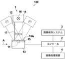
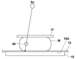
- FIG. 1 is a schematic configuration diagram of a radiation imaging system to which the image processing apparatus according to the first embodiment of the present disclosure is applied
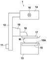
- FIG. 2 is a view of a mammography imaging device in the radiation imaging system as viewed from the direction of arrow A in FIG. be.
- the radiation imaging system 100 includes a mammography imaging device 1, a console 2, an image storage system 3, and an image processing device 4.
- the mammography imaging apparatus 1 photographs the breast M, which is a subject, from a plurality of radiation source positions in order to perform tomosynthesis imaging of the breast and generate a tomographic image, and acquires a plurality of radiographic images, that is, a plurality of projected images. Is for.
- the mammography imaging apparatus 1 can also perform simple imaging of irradiating the breast M with radiation from a predetermined radiation source position to acquire a two-dimensional radiographic image of the breast.
- the mammography photographing apparatus 1 includes an arm portion 12 connected to a base (not shown) by a rotating shaft 11.
- An imaging table 13 is attached to one end of the arm portion 12, and a radiation irradiation unit 14 is attached to the other end so as to face the photographing table 13.
- the arm portion 12 is configured so that only the end portion to which the radiation irradiation unit 14 is attached can be rotated, whereby the imaging table 13 can be fixed and only the radiation irradiation unit 14 can be rotated. It has become.
- a radiation detector 15 such as a flat panel detector is provided inside the photographing table 13.
- the radiation detector 15 has a radiation detection surface 15A.
- a charge amplifier that converts the charge signal read from the radiation detector 15 into a voltage signal
- a correlated double sampling circuit that samples the voltage signal output from the charge amplifier, and a voltage signal.
- a circuit board or the like provided with an AD (Analog Digital) conversion unit or the like for converting the voltage into a digital signal is also installed.
- the radiation source 16 is housed inside the radiation irradiation unit 14.
- the radiation source 16 emits X-rays as radiation, and the timing of irradiating the radiation from the radiation source 16 and the radiation generation conditions in the radiation source 16, that is, the selection of the material of the target and the filter, the tube voltage, the irradiation time, and the like are determined. It is controlled by the console 2.
- a compression plate 17 which is arranged above the imaging table 13 and presses and presses the breast M, a support portion 18 which supports the compression plate 17, and a support portion 18 are vertically attached to FIGS. 1 and 2.
- a moving mechanism 19 for moving in a direction is provided. The distance between the compression plate 17 and the photographing table 13, that is, the compression thickness is input to the console 2.
- the console 2 displays the shooting order and various information acquired from RIS (Radiology Information System), which is not shown, and instructions directly given by the engineer, etc., via a network such as a wireless communication LAN (Local Area Network). It has a function of controlling the mammography photographing apparatus 1 by using the device. Specifically, the console 2 acquires a plurality of projected images as described later by causing the mammography imaging device 1 to perform tomosynthesis imaging of the breast M. As an example, in this embodiment, the server computer is used as the console 2.
- the image storage system 3 is a system that stores image data such as a radiation image, a projection image, and a tomographic image taken by the mammography imaging device 1.
- the image storage system 3 extracts an image in response to a request from the console 2, the image processing device 4, and the like from the stored image, and transmits the image to the requesting device.
- Specific examples of the image storage system 3 include PACS (Picture Archiving and Communication Systems).
- the image processing device 4 according to the first embodiment includes the image generation device and the learning device according to the present disclosure, but in the following description, the image processing device will be represented.
- the hardware configuration of the image processing apparatus according to the first embodiment will be described with reference to FIG.
- the image processing device 4 is a computer such as a workstation, a server computer, and a personal computer, and includes a CPU (Central Processing Unit) 21, a non-volatile storage 23, and a memory 26 as a temporary storage area. Be prepared.
- a CPU Central Processing Unit
- the image processing device 4 includes a display 24 such as a liquid crystal display, an input device 25 such as a keyboard and a mouse, and a network I / F (InterFace) 27 connected to a network (not shown).
- the CPU 21, the storage 23, the display 24, the input device 25, the memory 26, and the network I / F 27 are connected to the bus 28.
- the CPU 21 is an example of the processor in the present disclosure.
- the storage 23 is realized by an HDD (Hard Disk Drive), an SSD (Solid State Drive), a flash memory, or the like.
- the storage 23 as a storage medium stores the image generation program 22A, the learning program 22B, and the image processing program 22C installed in the image processing device 4.
- the CPU 21 reads the image generation program 22A, the learning program 22B, and the image processing program 22C from the storage 23, expands them into the memory 26, and executes the expanded image generation program 22A, the learning program 22B, and the image processing program 22C.
- the image generation program 22A, the learning program 22B, and the image processing program 22C are stored in the storage device of the server computer connected to the network or the network storage in a state of being accessible from the outside, and are stored in the image processing device in a state of being accessible from the outside. It is downloaded and installed on the computers that make up 4. Alternatively, it is recorded and distributed on a recording medium such as a DVD (Digital Versatile Disc) or a CD-ROM (Compact Disc Read Only Memory), and the recording medium is installed in a computer constituting the image processing device 4.
- a recording medium such as a DVD (Digital Versatile Disc) or a CD-ROM (Compact Disc Read Only Memory)
- FIG. 4 is a diagram showing a functional configuration of the image processing apparatus according to the first embodiment.
- the image processing device 4 includes an image acquisition unit 31, a synthesis unit 32, a reconstruction unit 33, a teacher data generation unit 34, a learning unit 35, a detection unit 36, a display control unit 37, and a communication unit 38.
- the CPU 21 executes the image generation program 22A, the learning program 22B, and the image processing program 22C, so that the image processing device 4 has the image acquisition unit 31, the composition unit 32, the reconstruction unit 33, and the teacher data generation unit 34. It functions as a learning unit 35, a detection unit 36, a display control unit 37, and a communication unit 38.
- the learning model 36A which will be described later, is applied to the detection unit 36.
- the image acquisition unit 31, the composition unit 32, the reconstruction unit 33, the teacher data generation unit 34, the display control unit 37, and the communication unit 38 constitute the image generation device according to the first embodiment.
- the image acquisition unit 31 and the learning unit 35 constitute a learning device according to the first embodiment.
- the image acquisition unit 31, the detection unit 36, and the display control unit 37 constitute an image processing device according to the first embodiment.
- the image acquisition unit 31 acquires a plurality of projected images acquired by the console 2 causing the mammography imaging device 1 to perform tomosynthesis imaging. In addition, a lesion image of a simulated lesion that schematically represents the lesion contained in the breast M is acquired.
- the image acquisition unit 31 acquires a projected image from the console 2 or the image storage system 3 via the network I / F27.
- the image acquisition unit 31 acquires a lesion image from the image storage system 3 via the network I / F27.
- the image acquisition unit 31 acquires the teacher data generated as described later and stored in the image storage system 3 via the network I / F 27 for learning the learning model described later. Further, the image acquisition unit 31 acquires a target image to be detected of the lesion from the image storage system 3 via the network I / F 27, as will be described later.
- the console 2 moves the radiation source 16 by rotating the arm portion 12 around the rotation axis 11 when performing tomosynthesis imaging for generating a tomographic image, and at a plurality of radiation source positions due to the movement of the radiation source 16.
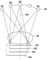
- FIG. 5 is a diagram for explaining the acquisition of the projected image Gi.
- the radiation source 16 is moved to each source position of S1, S2, ..., Sn, and the radiation source 16 is driven at each source position to irradiate the breast M with radiation, and the breast M is radiated.
- projected images G1, G2, ..., Gn are acquired corresponding to the respective source positions S1 to Sn.
- the projected image Gi will be referred to as a first projected image.
- the radiation source position Sc is the radiation source position where the optical axis X0 of the radiation emitted from the radiation source 16 is orthogonal to the detection surface 15A of the radiation detector 15.
- the radiation source position Sc shall be referred to as a reference radiation source position Sc.
- the synthesis unit 32 has a plurality of first units based on the geometrical relationship between the positions of the plurality of radiation sources when the mammography imaging apparatus 1 performs tomosynthesis imaging and the positions of the lesions arranged at predetermined positions in the breast M.
- a plurality of second projected images are derived by synthesizing the lesion image of the simulated lesion with the projected image Gi of. Examples of breast M lesions include tumors, spicula, and calcification.
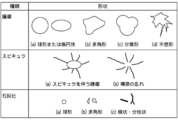
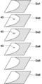
- FIG. 6 is a diagram showing lesion images of simulated lesions for various lesions.
- a lesion image of the simulated lesion an image similar to the actual shape of the lesion is prepared.
- a lesion image of a tumor a sphere or an ellipsoid, a polygon, a lobation type, and an irregular shape are prepared.
- a lesion image of Spicula a tumor accompanied by Spicula and a disorder of construction are prepared.
- Disordered construction refers to a condition without a mass.
- calcification lesion images spherical, polygonal, linear and lobulated ones are prepared.
- the lesion image of the simulated lesion may be obtained by radiography of the breast including the actual lesion, or may be artificially generated by computer graphics or the like. In this embodiment, a lesion image generated by computer graphics is used.
- the synthesizing unit 32 When synthesizing the lesion image with the first projected image Gi, the synthesizing unit 32 performs geometry of a plurality of radiation source positions when the mammography imaging apparatus 1 performs tomosynthesis imaging and the position of the lesion virtually arranged on the breast M. Based on the scientific relationship, first, the composite position of the lesion image with respect to the first projected image Gi is derived.
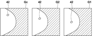
- FIG. 7 is a diagram for explaining the derivation of the synthetic position of the lesion image in the first embodiment. As shown in FIG. 7, it is assumed that the simulated lesion 40 is virtually arranged at a predetermined position in the breast M. As shown in FIG. 7, the radiation emitted from each source position S1 to Sn (only S1, S2, Sc are shown in FIG.
- the position on the detection surface 15A of the radiation detector 15 on which the radiation transmitted through the simulated lesion 40 is irradiated differs depending on the radiation source position. Therefore, as shown in FIG. 8, the position of the lesion image 42 of the simulated lesion 40 included in the first projected images G1, G2, Gc acquired at the source positions S1, S2, Sc is set for each source position. Will be different.
- the synthesis unit 32 detects the radiation source positions S1 to Sn, the positions of the simulated lesions 40 in the breast M, and the radiation detection when the simulated lesions 40 are virtually placed in the breast M and tomosynthesis is performed. From the geometrical relationship of the position of the detection surface 15A of the vessel 15, the composite position where the lesion image 42 is synthesized in the first projected image Gi is derived.
- the radiation emitted from the radiation source 16 when performing tomosynthesis imaging passes through the air existing between the radiation source 16 and the compression plate 17, the compression plate 17, the breast M, and the top plate 13A of the imaging table 13. Then, the radiation detector 15 is irradiated. Therefore, the radiation emitted from the radiation source 16 is attenuated by the air, the compression plate 17, the breast M, and the top plate 13A and irradiated to the radiation detector 15, and is detected as the first projected image Gi.
- the radiation detector 15 is irradiated through the compression plate 17, the simulated lesion 40, and the top plate 13A of the imaging table 13.
- the synthesis unit 32 synthesizes the lesion image 42 of the simulated lesion 40 at the composite position of the first projected image Gi, the radiation representing the attenuation of the radiation transmitted through the simulated lesion 40.
- the attenuation coefficient is derived, and the lesion image 42 of the simulated lesion 40 is combined with the first projected image Gi at the composite position based on the radiation attenuation coefficient to derive the second projected image CGi.
- the derivation of the radiation attenuation coefficient of the simulated lesion 40 will be described.
- the radiation generation conditions (that is, the target and filter, and the tube voltage) when the first projected image Gi is acquired are known and can be acquired from the console 2.
- the synthesis unit 32 acquires the radiation irradiation spectrum P0 when the first projected image Gi is acquired from the radiation generation conditions.
- a table that defines the relationship between various radiation generation conditions and the irradiation spectrum P0 is prepared in advance and stored in the storage 23.
- the synthesis unit 32 refers to the table stored in the storage 23 and acquires the radiation irradiation spectrum P0 when the first projected image Gi is acquired from the radiation generation conditions acquired from the console 2.
- the attenuation of radiation occurs in the same way at any source position Si. Therefore, in the present embodiment, the radiation attenuation coefficient of the simulated lesion 40 is subsequently derived based on the reference radiation source position Sc, but the present invention is not limited to this.
- the synthesis unit 32 derives the path length of the radiation emitted from the reference radiation source position Sc and incident on the simulated lesion 40 when passing through the simulated lesion 40 as the thickness t1 of the simulated lesion 40.
- the radiation attenuation coefficient ⁇ 1 of the simulated lesion 40 for each radiation energy is known for each type of lesion. Therefore, the synthesis unit 32 has passed through the simulated lesion 40 by the following formula (1) from the radiation spectrum P0, the radiation attenuation coefficient ⁇ 1 of the simulated lesion 40 for each radiation energy, and the thickness t1 of the simulated lesion 40.
- the synthesis unit 32 derives the radiation attenuation coefficient ⁇ m of the simulated lesion 40 over the entire energy range of the radiation from the radiation spectrum P0 and the radiation spectrum P1 for each energy of the radiation by the following equation (2).
- the synthesis unit 32 synthesizes the lesion image 42 at the composite position in the first projected image Gi derived as described above, and synthesizes the lesion image 42 to the second projection image Gi.
- the projected image CGi is derived.
- the second projected image CGi is derived by deriving the pixel value of the projected image CGi at the composite position (x, y) by the following equation (3).
- G (x, y) is the composite position in the first projected image Gi
- CG (x, y) is the composite position in the second projected image CGi
- l (x, y) is the composite position.
- CG (x, y) G (x, y) - ⁇ m ⁇ l (x, y) (3)
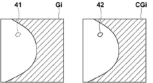
- FIG. 9 is a diagram showing a first projected image Gi and a second projected image CGi. As shown in FIG. 9, in the second projected image CGi, the lesion image 42 of the simulated lesion 40 is included in the composite position 41 in the first projected image Gi.
- the synthesis unit 32 generates a second projected image CGi including lesion images of various types of simulated lesions having various shapes as shown in FIG.
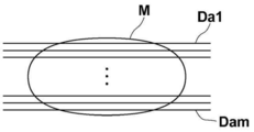
- a well-known back projection method such as a simple back projection method or a filter back projection method
- a three-dimensional image of the breast M is composed of a plurality of tomographic images Daj generated by the reconstruction. Further, as shown in FIG. 11, the generated tomographic image Daj includes a tomographic image 43 of the simulated lesion 40 virtually arranged in the breast M when the second projected image CGi is generated. There is something. In FIG. 11, a tomographic image 43 of the simulated lesion 40 is included over the tomographic images Da2, Da3, and Da4. In the following description, the tomographic image Daj including the simulated lesion 40 will be referred to as an abnormal image. Further, in the following description, it is assumed that the reference code Daj may be used as the abnormal image.
- the teacher data generation unit 34 includes the abnormal image generated as described above (that is, the tomographic image Daj including the tomographic image 43 of the simulated lesion 40) and the data representing the position of the tomographic image 43 included in each abnormal image Daj (hereinafter,). , Correct answer data) and the teacher data Tj is generated.
- FIG. 12 is a diagram schematically showing the teacher data generated in the first embodiment.
- the teacher data Tj consists of an abnormal image Daj including a tomographic image 43 of the simulated lesion 40 and correct data Cj representing the position of the tomographic image 43 of the simulated lesion 40 in the abnormal image Daj.
- the teacher data is generated for each abnormal image Daj.
- the teacher data Tj generated by the teacher data generation unit 34 is stored in the storage 23.
- the generated abnormal image Daj may be displayed on the display 24 by the display control unit 37. Further, the communication unit 38 transmits the teacher data Tj to the image storage system 3. The image storage system 3 stores the received teacher data Tj.
- the learning unit 35 uses the teacher data Tj for the abnormal image as the first teacher data and the teacher data for the medical image that does not include the lesion as the second teacher data, respectively, and uses the region of the lesion in the input target image.
- the learning model 36A possessed by the detection unit 36 is constructed.
- a plurality of first and second teacher data are prepared. Therefore, when learning the machine learning model, the image acquisition unit 31 acquires a plurality of first and second teacher data from the storage 23 or the image storage system 3.
- An example of a machine learning model for constructing a learning model 36A is a neural network model.
- the neural network model include a simple perceptron, a multi-layer perceptron, a deep neural network, a convolutional neural network, a deep belief network, a recurrent neural network, and a stochastic neural network.
- a convolutional neural network is used as a machine learning model for constructing the learning model 36A.
- the learning model 36A learns a machine learning model so that when the abnormal image Daj included in the teacher data is input, the probability (probability) that each pixel of the abnormal image Daj is a lesion region is output. It is built by.
- the region composed of pixels whose probability is equal to or higher than a predetermined threshold value output by the learning model 36A is the lesion region.
- the learning unit 35 inputs the abnormal image into the machine learning model, and outputs the probability of becoming a lesion region for each pixel of the abnormal image. Then, the difference between the region consisting of pixels output by the machine learning model, which has a probability of exceeding a predetermined threshold value, and the region represented by the correct answer data included in the teacher data is derived as a loss.
- the machine learning model is learned based on the loss.
- the kernel coefficient in the convolutional neural network, the weight of the connection of the neural network, and the like are derived so as to reduce the loss.
- the learning unit 35 repeats learning until the loss becomes equal to or less than a predetermined threshold value.
- the lesion area included in the input target image is extracted by outputting a high probability equal to or higher than a predetermined threshold value.
- the learning model 36A is constructed.
- the learning model 36A constructed by the learning unit 35 is applied to the detection unit 36.
- the detection unit 36 detects the lesion area by causing the learning model 36A to detect the lesion area included in the target image.
- the image acquisition unit 31 acquires a projected image (referred to as the target projected image) to be the target image from the mammography imaging device 1 or the image storage system 3. ..
- the reconstruction unit 33 generates the target tomographic image by reconstructing the target projection image.
- the detection unit 36 detects the lesion area from the target tomographic image.
- the console 2 of the mammography imaging apparatus 1 may generate a target tomographic image from the target projected image. In this case, the image acquisition unit 31 acquires the target tomographic image from the console 2. Further, when the target tomographic image generated from the target projected image is stored in the image storage system 3, the image acquisition unit 31 may acquire the target tomographic image from the image storage system 3.
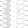
- FIG. 13 is a diagram showing a target tomographic image and a detection result of a lesion area.
- the detection unit 36 detects the lesion region from, for example, six target tomographic images DT1 to DT6, and outputs the detection results R1 to R6.
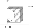
- FIG. 14 is a diagram showing a display screen of the detection result of the target tomographic image in the first embodiment.
- the first target tomographic image DT1 of the six target tomographic images DT1 to DT6 shown in FIG. 13 is displayed on the display screen 50.
- the displayed target tomographic image can be switched by operating from the input device 25.
- the display control unit 37 emphasizes the lesion area 52 in the target tomographic image DT1 by surrounding the lesion area 52 included in the target tomographic image DT1 with a rectangular frame 53.
- the rectangular frame 53 is shown in white in FIG. 14, a color may be added.
- the area of the lesion may be emphasized by adding marks such as arrows and stars in the vicinity of the area of the lesion.
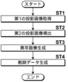
- FIG. 15 is a flowchart of the image generation process performed in the first embodiment.
- the image acquisition unit 31 acquires a plurality of first projected images Gi (step ST1).
- the synthesis unit 32 first projects the first projection based on the geometrical relationship between the positions of the plurality of radiation sources when the mammography imaging apparatus 1 performs tomosynthesis imaging and the positions of the simulated lesions virtually arranged on the breast M.
- a plurality of second projected images CGi are derived by synthesizing the lesion image 42 with the image Gi (step ST2).
- the reconstruction unit 33 reconstructs a plurality of second projected images CGi to obtain a tomographic image emphasizing the desired tomographic surface of the breast M, which includes a tomographic image 43 of the simulated lesion 40.
- the teacher data generation unit 34 generates teacher data Tj including the abnormal image Daj generated as described above and the correct answer data Cj representing the position of the tomographic image 43 of the simulated lesion 40 included in each abnormal image Daj.
- Step ST4 the process is terminated.
- the generated teacher data Tj is stored in the storage 23, and is further transmitted to the image storage system 3 by the communication unit 38.
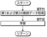
- FIG. 16 is a flowchart of the learning process performed in the first embodiment.
- the image acquisition unit 31 acquires the first and second teacher data (step ST11), and the learning unit 35 uses the first and second machine learning models for constructing the learning model 36A of the detection unit 36.
- the teacher data is input to acquire the extraction result of the lesion area, the machine learning model is learned using the loss based on the difference from the correct answer data (step ST12), and the process returns to step ST11.
- the learning unit 35 repeats the processes of steps ST11 and ST12 until the loss reaches a predetermined threshold value, and ends the learning of the machine learning model.
- the learning model 36A is constructed.
- the learning unit 35 may end the learning by repeating the learning a predetermined number of times.
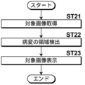
- FIG. 17 is a flowchart of the detection process performed in the first embodiment.
- the image acquisition unit 31 acquires the target image (target tomographic image DTj) to be detected (step ST21), and the detection unit 36 detects the lesion region from the target image (step ST22). Then, the display control unit 37 displays the target image in which the lesion area is emphasized on the display 24 (step ST23), and ends the process.
- the tomographic image Daj including the tomographic image 43 of the simulated lesion 40 is obtained by using the second projected image CGi generated by synthesizing the lesion image 42 of the simulated lesion 40 with the first projected image Gi. Changed to generate as an abnormal image. Therefore, by changing the type of the simulated lesion 40 and changing the position where the simulated lesion 40 is installed, a tomographic image containing various types of lesions at various positions is generated as an abnormal image. can do. Therefore, a sufficient number and sufficient variations of abnormal images can be prepared for learning a machine learning model for constructing the learning model 36A.
- a learning model 36A for discriminating the lesion region from the input target image is constructed by machine learning using the first teacher image consisting of the abnormal image and the data including the information indicating the position of the lesion image in the abnormal image. I did.
- a sufficient number and sufficient variations of abnormal images, and a first teacher data can be prepared for learning the machine learning model for constructing the learning model 36A. .. Therefore, according to the present embodiment, it is possible to construct a learning model 36A having high lesion detection accuracy.
- the second projected image CGi is derived based on the radiation attenuation coefficient ⁇ m of the simulated lesion 40, the second projected image CGi similar to the case where the breast M including the lesion is actually photographed is acquired. can do. Therefore, a learning model 36A with high lesion detection accuracy can be constructed.
- the configuration of the image processing apparatus according to the second embodiment is the same as the configuration of the image processing apparatus 4 according to the first embodiment, and only the processing to be performed is different. Therefore, a detailed description of the apparatus will be described here. Omit.
- the lesion image 42 of the simulated lesion 40 is combined with the first projected image Gi acquired by tomosynthesis imaging to generate a second projected image CGi, and the second projected image CGi is generated.
- the tomographic image was generated as an abnormal image from.
- the second embodiment is different from the second embodiment in that an image obtained by synthesizing the lesion image 42 of the simulated lesion 40 with the radiographic image acquired by simple radiography is generated as an abnormal image.
- the image processing device according to the second embodiment does not require the reconstruction unit 33 according to the first embodiment, the image processing device according to the second embodiment does not include the reconstruction unit 33. good.
- the mammography imaging apparatus 1 acquires the radiation image H0 of the breast M by performing a simple imaging in which the breast M is irradiated only from the reference radiation source position Sc.
- the image acquisition unit 31 acquires a radiation image H0 of the breast M by simple radiography.
- the synthesis unit 32 synthesizes the lesion image 42 of the simulated lesion 40 at the synthesis position of the radiographic image H0.
- FIG. 18 is a diagram for explaining the synthetic position of the lesion image 42 of the simulated lesion 40 in the second embodiment.
- the breast M is imaged only at the reference source position Sc. Therefore, the synthesis unit 32 is based on the geometric relationship between the reference radiation source position Sc, the arrangement position of the simulated lesion 40 virtually arranged in the breast M, and the position of the detection surface 15A of the radiation detector 15.
- the synthetic position where the lesion image 42 is synthesized in the radiographic image H0 is derived.
- the synthesis unit 32 derives the radiation attenuation coefficient ⁇ m of the simulated lesion 40 by simulating the radiation attenuation in the same manner as in the first embodiment, and uses the radiation attenuation coefficient ⁇ m as described above.
- the lesion image 42 is synthesized at the composite position in the derived radiographic image H0 to generate the abnormal image H1.
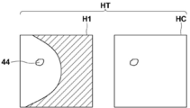
- the teacher data generation unit 34 generates teacher data HT including the abnormal image H1 generated as described above and data representing the position of the lesion image included in the abnormal image H1 (referred to as correct answer data).
- FIG. 19 is a diagram schematically showing the teacher data generated in the second embodiment. As shown in FIG. 19, the teacher data HT consists of an abnormal image H1 including the lesion image 44 of the simulated lesion 40 and correct data HC representing the position of the lesion image 44 of the simulated lesion 40 in the abnormal image H1.
- the teacher data HT generated by the teacher data generation unit 34 is stored in the storage 23.
- the generated abnormal image H1 may be displayed on the display 24 by the display control unit 37. Further, the communication unit 38 transmits the teacher data HT to the image storage system 3. The image storage system 3 stores the received teacher data HT.
- the learning unit 35 uses the teacher data HT for the abnormal image H1 as the first teacher data and the teacher data for the medical image not including the lesion as the second teacher data. Then, the learning model 36A possessed by the detection unit 36 is constructed by learning the machine learning model so as to discriminate the region of the lesion in the target image acquired by the input simple imaging. A plurality of first and second teacher data are prepared. Therefore, when learning the machine learning model, the image acquisition unit 31 acquires a plurality of first and second teacher data from the storage 23 or the image storage system 3. Since the learning process performed by the learning unit 35 is the same as that of the first embodiment except that the teacher data is a tomographic image, detailed description thereof will be omitted here.
- the detection unit 36 detects the lesion area by causing the learning model 36A to detect the lesion area included in the target image. do.
- the display control unit 37 emphasizes the area of the lesion detected by the detection unit 36 from the target image and displays the target image on the display 24.
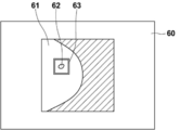
- FIG. 20 is a diagram showing a display screen of the detection result of the target image in the second embodiment. As shown in FIG. 20, the target image 61 is displayed on the display screen 60. The display control unit 37 emphasizes the lesion area 62 in the target image 61 by surrounding the lesion area 62 included in the target image 61 with a rectangular frame 63.
- FIG. 21 is a flowchart of the image generation process performed in the second embodiment.
- the image acquisition unit 31 acquires the radiation image H0 for generating an abnormal image (step ST31).
- the synthesis unit 32 displays the lesion image on the radiographic image H0 based on the geometrical relationship between the radiation source position when the mammography imaging device 1 takes an image and the position of the simulated lesion virtually arranged on the breast M.
- the abnormal image H1 is generated by combining (step ST32).
- the teacher data generation unit 34 generates teacher data including correct answer data representing the positions of the abnormal image H1 and the lesion image included in the abnormal image H1 (step ST33), and ends the process.
- the generated teacher data is stored in the storage 23, and further transmitted to the image storage system 3 by the communication unit 38.
- the learning process in the second embodiment is the same as that in the first embodiment except that the teacher data consists of the abnormal image H1 and the correct answer data. Further, the lesion detection process in the second embodiment is the same as that in the first embodiment except that the target image is a radiographic image acquired by simple radiography. Therefore, detailed description of the learning process and the lesion detection process in the second embodiment will be omitted.
- the lesion image 42 of the simulated lesion 40 is combined with the plurality of tomographic images to generate an abnormal image Daj including the tomographic image 43 of the simulated lesion 40. Therefore, a composite two-dimensional image may be generated by using a plurality of abnormal image Daj.
- the composite two-dimensional image is a pseudo two-dimensional image corresponding to a simple two-dimensional image by synthesizing a plurality of tomographic images including anomalous images by an addition method, an average method, a maximum value projection method, a minimum value projection method, or the like. It is an image (see JP-A-2014-128716).
- FIG. 22 is a diagram for explaining the generation of a composite two-dimensional image.
- the composite two-dimensional image may be generated by the composite unit 32, or a composite two-dimensional image generation unit may be provided for generating the composite two-dimensional image, and the composite two-dimensional image generation unit may generate the composite two-dimensional image.
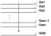
- the synthesizing unit 32 in a state where a plurality of abnormal images Daj are stacked, is directed toward the radiation detector 15 from the reference radiation source position Sc, that is, along the optical axis X0 shown in FIG. , Pixel values of corresponding pixel positions of a plurality of tomographic images including an abnormal image are combined to generate a composite two-dimensional image GG0.
- the teacher data generation unit 34 When the synthetic two-dimensional image GG0 is generated in this way, the teacher data generation unit 34 generates teacher data from the synthetic two-dimensional image GG0 and the data representing the position of the lesion image of the simulated lesion 40 included in the synthetic two-dimensional image GG0. Generate.
- the learning unit 35 learns the machine learning model using the teacher data so as to detect the lesion included in the synthetic two-dimensional image, so that the learning model 36A in the detection unit 36 To build.
- the learning model 36A constructed in this way when the synthetic two-dimensional image is input to the detection unit 36 as the target image, the lesion can be detected from the target image which is the synthetic two-dimensional image.
- the method for generating a composite two-dimensional image is not limited to the above method.
- a composite two-dimensional image is generated by synthesizing only the tomographic image included in the abnormal image Daj with an arbitrary tomographic image prepared in advance. May be good.
- a composite two-dimensional image may be generated by synthesizing only the tomographic images included in the abnormal image Daj by averaging them.
- the radiation in the above embodiment is not particularly limited, and ⁇ -rays, ⁇ -rays, etc. can be applied in addition to X-rays.
- the subject is the breast M, but the subject is not limited to this.
- any part of the human body such as the heart, liver, brain, and limbs can be the subject.
- the simulated lesion may be of a type suitable for the subject.
- the learning model 36A of the detection unit 36 is prepared to detect the lesion according to the subject, and learning is performed by the teacher data including the generated abnormal image, and the detection unit 36 detects the lesion according to the subject. Will be done.
- various processes such as an image acquisition unit 31, a synthesis unit 32, a reconstruction unit 33, a teacher data generation unit 34, a learning unit 35, a detection unit 36, a display control unit 37, and a communication unit 38 are performed.
- various processors Processors
- the various processors include a CPU, which is a general-purpose processor that executes software (program) and functions as various processing units, and a circuit after manufacturing an FPGA (Field Programmable Gate Array) or the like.
- Dedicated electricity which is a processor with a circuit configuration specially designed to execute specific processing such as programmable logic device (PLD), ASIC (Application Specific Integrated Circuit), which is a processor whose configuration can be changed. Circuits and the like are included.
- One processing unit may be composed of one of these various processors, or a combination of two or more processors of the same type or different types (for example, a combination of a plurality of FPGAs or a combination of a CPU and an FPGA). ) May be configured. Further, a plurality of processing units may be configured by one processor.
- one processor is configured by combining one or more CPUs and software. There is a form in which this processor functions as a plurality of processing units.
- SoC System On Chip
- the various processing units are configured by using one or more of the above-mentioned various processors as a hardware structure.
- circuitry in which circuit elements such as semiconductor elements are combined can be used.
Landscapes
- Engineering & Computer Science (AREA)
- Health & Medical Sciences (AREA)
- Life Sciences & Earth Sciences (AREA)
- Physics & Mathematics (AREA)
- Medical Informatics (AREA)
- Theoretical Computer Science (AREA)
- General Physics & Mathematics (AREA)
- General Health & Medical Sciences (AREA)
- Nuclear Medicine, Radiotherapy & Molecular Imaging (AREA)
- Radiology & Medical Imaging (AREA)
- Molecular Biology (AREA)
- Biomedical Technology (AREA)
- Biophysics (AREA)
- High Energy & Nuclear Physics (AREA)
- Veterinary Medicine (AREA)
- Public Health (AREA)
- Animal Behavior & Ethology (AREA)
- Surgery (AREA)
- Heart & Thoracic Surgery (AREA)
- Pathology (AREA)
- Optics & Photonics (AREA)
- Computer Vision & Pattern Recognition (AREA)
- Mathematical Physics (AREA)
- Quality & Reliability (AREA)
- Computational Linguistics (AREA)
- Algebra (AREA)
- General Engineering & Computer Science (AREA)
- Computing Systems (AREA)
- Evolutionary Computation (AREA)
- Data Mining & Analysis (AREA)
- Software Systems (AREA)
- Dentistry (AREA)
- Physiology (AREA)
- Oral & Maxillofacial Surgery (AREA)
- Artificial Intelligence (AREA)
- Mathematical Analysis (AREA)
- Mathematical Optimization (AREA)
- Pure & Applied Mathematics (AREA)
- Apparatus For Radiation Diagnosis (AREA)
Priority Applications (3)
| Application Number | Priority Date | Filing Date | Title |
|---|---|---|---|
| JP2022505970A JP7513697B2 (ja) | 2020-03-13 | 2021-03-03 | 画像生成装置およびプログラム、学習装置およびプログラム、並びに画像処理装置およびプログラム |
| EP21766927.4A EP4119055B1 (en) | 2020-03-13 | 2021-03-03 | Image generation device and program, learning device and program, and image processing device and program |
| US17/818,362 US12417565B2 (en) | 2020-03-13 | 2022-08-09 | Image generation device, image generation program, learning device, learning program, image processing device, and image processing program |
Applications Claiming Priority (2)
| Application Number | Priority Date | Filing Date | Title |
|---|---|---|---|
| JP2020044697 | 2020-03-13 | ||
| JP2020-044697 | 2020-03-13 |
Related Child Applications (1)
| Application Number | Title | Priority Date | Filing Date |
|---|---|---|---|
| US17/818,362 Continuation US12417565B2 (en) | 2020-03-13 | 2022-08-09 | Image generation device, image generation program, learning device, learning program, image processing device, and image processing program |
Publications (1)
| Publication Number | Publication Date |
|---|---|
| WO2021182229A1 true WO2021182229A1 (ja) | 2021-09-16 |
Family
ID=77670717
Family Applications (1)
| Application Number | Title | Priority Date | Filing Date |
|---|---|---|---|
| PCT/JP2021/008162 Ceased WO2021182229A1 (ja) | 2020-03-13 | 2021-03-03 | 画像生成装置およびプログラム、学習装置およびプログラム、並びに画像処理装置およびプログラム |
Country Status (4)
| Country | Link |
|---|---|
| US (1) | US12417565B2 (enExample) |
| EP (1) | EP4119055B1 (enExample) |
| JP (1) | JP7513697B2 (enExample) |
| WO (1) | WO2021182229A1 (enExample) |
Cited By (1)
| Publication number | Priority date | Publication date | Assignee | Title |
|---|---|---|---|---|
| WO2025150130A1 (ja) * | 2024-01-11 | 2025-07-17 | 富士通株式会社 | 病変識別方法および病変識別プログラム |
Families Citing this family (2)
| Publication number | Priority date | Publication date | Assignee | Title |
|---|---|---|---|---|
| JP7413216B2 (ja) * | 2020-09-15 | 2024-01-15 | 富士フイルム株式会社 | 学習装置、方法およびプログラム、学習済みモデル、並びに放射線画像処理装置、方法およびプログラム |
| CN116128320B (zh) * | 2023-01-04 | 2023-08-08 | 杭州有泰信息技术有限公司 | 电网输变电可视化管控方法及平台 |
Citations (8)
| Publication number | Priority date | Publication date | Assignee | Title |
|---|---|---|---|---|
| JP2007283108A (ja) * | 2006-04-17 | 2007-11-01 | Siemens Medical Solutions Usa Inc | 画像の位置合わせを容易にするシステム及び方法 |
| JP2008048880A (ja) * | 2006-08-24 | 2008-03-06 | Ge Medical Systems Global Technology Co Llc | 画像作成方法 |
| JP2008229161A (ja) | 2007-03-22 | 2008-10-02 | Fujifilm Corp | 画像成分分離装置、方法、およびプログラム、ならびに、正常画像生成装置、方法、およびプログラム |
| JP2014128716A (ja) | 2008-11-21 | 2014-07-10 | Hologic Inc | トモシンセシスデータセットから2d画像を生成するためのシステムおよび方法 |
| US8983156B2 (en) | 2012-11-23 | 2015-03-17 | Icad, Inc. | System and method for improving workflow efficiences in reading tomosynthesis medical image data |
| US9792703B2 (en) | 2015-07-06 | 2017-10-17 | Siemens Healthcare Gmbh | Generating a synthetic two-dimensional mammogram |
| WO2017221537A1 (ja) * | 2016-06-21 | 2017-12-28 | 株式会社日立製作所 | 画像処理装置、及び方法 |
| JP2020018705A (ja) * | 2018-08-02 | 2020-02-06 | キヤノンメディカルシステムズ株式会社 | 医用画像処理装置、画像生成方法、及び画像生成プログラム |
Family Cites Families (28)
| Publication number | Priority date | Publication date | Assignee | Title |
|---|---|---|---|---|
| US8571289B2 (en) | 2002-11-27 | 2013-10-29 | Hologic, Inc. | System and method for generating a 2D image from a tomosynthesis data set |
| US7616801B2 (en) | 2002-11-27 | 2009-11-10 | Hologic, Inc. | Image handling and display in x-ray mammography and tomosynthesis |
| US7123684B2 (en) | 2002-11-27 | 2006-10-17 | Hologic, Inc. | Full field mammography with tissue exposure control, tomosynthesis, and dynamic field of view processing |
| US10638994B2 (en) | 2002-11-27 | 2020-05-05 | Hologic, Inc. | X-ray mammography with tomosynthesis |
| US8565372B2 (en) | 2003-11-26 | 2013-10-22 | Hologic, Inc | System and method for low dose tomosynthesis |
| US7577282B2 (en) | 2002-11-27 | 2009-08-18 | Hologic, Inc. | Image handling and display in X-ray mammography and tomosynthesis |
| US7831296B2 (en) | 2002-11-27 | 2010-11-09 | Hologic, Inc. | X-ray mammography with tomosynthesis |
| US8768026B2 (en) | 2003-11-26 | 2014-07-01 | Hologic, Inc. | X-ray imaging with x-ray markers that provide adjunct information but preserve image quality |
| WO2006055830A2 (en) | 2004-11-15 | 2006-05-26 | Hologic, Inc. | Matching geometry generation and display of mammograms and tomosynthesis images |
| EP1816965B1 (en) | 2004-11-26 | 2016-06-29 | Hologic, Inc. | Integrated multi-mode mammography/tomosynthesis x-ray system |
| US10008184B2 (en) | 2005-11-10 | 2018-06-26 | Hologic, Inc. | System and method for generating a 2D image using mammography and/or tomosynthesis image data |
| JP5125500B2 (ja) * | 2007-12-29 | 2013-01-23 | オムロン株式会社 | X線断層撮影のシミュレーション方法およびシミュレーション用のプログラム |
| KR102109588B1 (ko) | 2011-11-27 | 2020-05-12 | 홀로직, 인크. | 유방 조직 이미지를 프로세싱하고, 디스플레잉하고, 네비게이팅하기 위한 방법 |
| GB2533632B (en) * | 2014-12-24 | 2018-01-03 | Gen Electric | Method and system for obtaining low dose tomosynthesis and material decomposition images |
| WO2017116512A1 (en) * | 2015-12-28 | 2017-07-06 | Metritrack, Inc. | System and method for the coregistration of medical image data |
| JP6566887B2 (ja) * | 2016-02-16 | 2019-08-28 | 富士フイルム株式会社 | 放射線画像処理装置、方法およびプログラム |
| US20170337682A1 (en) * | 2016-05-18 | 2017-11-23 | Siemens Healthcare Gmbh | Method and System for Image Registration Using an Intelligent Artificial Agent |
| EP3254623B1 (en) * | 2016-06-09 | 2020-09-16 | Agfa Nv | Method and system for correcting geometric misalignment during image reconstruction in chest tomosynthesis |
| US10165997B2 (en) * | 2016-07-05 | 2019-01-01 | Siemens Healthcare Gmbh | System for acquiring a three-dimensional image of arteries and veins |
| JP7123919B2 (ja) * | 2016-10-28 | 2022-08-23 | エセンシャル ロボティクス | X線撮像システムの軌道を決定する方法及びシステム |
| EP3400878B1 (en) * | 2017-05-10 | 2020-03-25 | Esaote S.p.A. | Method for postural independent location of targets in diagnostic imagines acquired by multimodal acquisitions and system for carrying out the said method |
| JP6824133B2 (ja) * | 2017-09-28 | 2021-02-03 | 富士フイルム株式会社 | 画像処理装置、画像処理方法、及び画像処理プログラム |
| JP6917913B2 (ja) * | 2018-01-17 | 2021-08-11 | 富士フイルム株式会社 | 画像処理装置、画像処理方法、及び画像処理プログラム |
| JP7113447B2 (ja) * | 2018-03-12 | 2022-08-05 | 東芝エネルギーシステムズ株式会社 | 医用画像処理装置、治療システム、および医用画像処理プログラム |
| CN108986182B (zh) * | 2018-07-10 | 2022-11-25 | 上海联影医疗科技股份有限公司 | 一种重建ct图像的方法、系统及存储介质 |
| US11857358B2 (en) * | 2018-09-28 | 2024-01-02 | Hologic, Inc. | System and method for synthetic breast tissue image generation by high density element suppression |
| US11331162B2 (en) * | 2020-01-13 | 2022-05-17 | Imaging For Women, L.L.C. | Surface markers for 3D supine automated ultrasound imaging and use thereof |
| US11564645B2 (en) * | 2020-02-25 | 2023-01-31 | GE Precision Healthcare LLC | Methods and systems for digital mammography imaging |
-
2021
- 2021-03-03 JP JP2022505970A patent/JP7513697B2/ja active Active
- 2021-03-03 WO PCT/JP2021/008162 patent/WO2021182229A1/ja not_active Ceased
- 2021-03-03 EP EP21766927.4A patent/EP4119055B1/en active Active
-
2022
- 2022-08-09 US US17/818,362 patent/US12417565B2/en active Active
Patent Citations (8)
| Publication number | Priority date | Publication date | Assignee | Title |
|---|---|---|---|---|
| JP2007283108A (ja) * | 2006-04-17 | 2007-11-01 | Siemens Medical Solutions Usa Inc | 画像の位置合わせを容易にするシステム及び方法 |
| JP2008048880A (ja) * | 2006-08-24 | 2008-03-06 | Ge Medical Systems Global Technology Co Llc | 画像作成方法 |
| JP2008229161A (ja) | 2007-03-22 | 2008-10-02 | Fujifilm Corp | 画像成分分離装置、方法、およびプログラム、ならびに、正常画像生成装置、方法、およびプログラム |
| JP2014128716A (ja) | 2008-11-21 | 2014-07-10 | Hologic Inc | トモシンセシスデータセットから2d画像を生成するためのシステムおよび方法 |
| US8983156B2 (en) | 2012-11-23 | 2015-03-17 | Icad, Inc. | System and method for improving workflow efficiences in reading tomosynthesis medical image data |
| US9792703B2 (en) | 2015-07-06 | 2017-10-17 | Siemens Healthcare Gmbh | Generating a synthetic two-dimensional mammogram |
| WO2017221537A1 (ja) * | 2016-06-21 | 2017-12-28 | 株式会社日立製作所 | 画像処理装置、及び方法 |
| JP2020018705A (ja) * | 2018-08-02 | 2020-02-06 | キヤノンメディカルシステムズ株式会社 | 医用画像処理装置、画像生成方法、及び画像生成プログラム |
Non-Patent Citations (2)
| Title |
|---|
| ABE, KAZUYA ET AL.: "Creation of new artificial calcification shadows for breast cancer and verification of effectiveness of CAD development method without any empirical examples", MEDICAL IMAGING TECHNOLOGY, vol. 35, no. 5, 2017, pages 268 - 272, XP055856990 * |
| LI HUI, GIGER MARYELLEN L., HUYNH BENJAMIN Q., ANTROPOVA NATALIA O.: "Deep learning in breast cancer risk assessment: evaluation of convolutional neural networks on a clinical dataset of full-field digital mammograms", JOURNAL OF MEDICAL IMAGING, vol. 4, no. 4, 2017, pages 1 - 4, XP055856994 * |
Cited By (1)
| Publication number | Priority date | Publication date | Assignee | Title |
|---|---|---|---|---|
| WO2025150130A1 (ja) * | 2024-01-11 | 2025-07-17 | 富士通株式会社 | 病変識別方法および病変識別プログラム |
Also Published As
| Publication number | Publication date |
|---|---|
| JP7513697B2 (ja) | 2024-07-09 |
| JPWO2021182229A1 (enExample) | 2021-09-16 |
| EP4119055A1 (en) | 2023-01-18 |
| US20220383564A1 (en) | 2022-12-01 |
| US12417565B2 (en) | 2025-09-16 |
| EP4119055A4 (en) | 2023-08-09 |
| EP4119055B1 (en) | 2024-10-30 |
Similar Documents
| Publication | Publication Date | Title |
|---|---|---|
| US7142633B2 (en) | Enhanced X-ray imaging system and method | |
| KR20240013724A (ko) | 다중 펄스 x-선 소스 이동 단층합성 영상화 시스템을 사용한 인공 지능 훈련 | |
| JP7084291B2 (ja) | トモシンセシス撮影支援装置、方法およびプログラム | |
| US12417565B2 (en) | Image generation device, image generation program, learning device, learning program, image processing device, and image processing program | |
| JP2021029698A (ja) | 画像表示装置、方法およびプログラム、画像管理装置、方法およびプログラム | |
| JP2020048991A (ja) | 断層画像生成装置、方法およびプログラム | |
| US12315145B2 (en) | Image processing device, learning device, radiography system, image processing method, learning method, image processing program, and learning program | |
| US12056875B2 (en) | Image processing device, learning device, radiography system, image processing method, learning method, image processing program, and learning program | |
| JP2020005706A (ja) | 画像表示装置、方法およびプログラム | |
| JP7686430B2 (ja) | 推定装置、方法およびプログラム | |
| JPWO2021182229A5 (enExample) | ||
| JP7758830B2 (ja) | 推定装置、方法およびプログラム | |
| JP2021045268A (ja) | 画像処理装置、方法およびプログラム、並びに画像表示装置、方法およびプログラム | |
| JP7209599B2 (ja) | 画像処理装置、方法およびプログラム | |
| WO2020202612A1 (ja) | 画像処理装置、方法およびプログラム | |
| JP2021019930A (ja) | 画像処理装置、方法およびプログラム | |
| WO2021186957A1 (ja) | 画像処理装置、方法およびプログラム | |
| JP7542477B2 (ja) | 画像処理装置、画像処理方法、及び画像処理プログラム | |
| JP2025040874A (ja) | 画像処理装置、放射線画像撮影システム及びプログラム | |
| JP7430814B2 (ja) | 画像処理装置、画像処理方法、及び画像処理プログラム | |
| JP2025051943A (ja) | 画像処理装置、放射線画像撮影システム及びプログラム | |
| CN119488309A (zh) | 用于改善重建的2d/3d图像中的伪影校正的系统和方法 | |
| JP2025149688A (ja) | 画像処理装置、画像処理方法、及び画像処理プログラム | |
| Vedantham et al. | Breast Cancer Screening: Opportunities and Challenges with Fully 3D Tomographic X-Ray Imaging | |
| WO2021186956A1 (ja) | 画像処理装置、方法およびプログラム |
Legal Events
| Date | Code | Title | Description |
|---|---|---|---|
| 121 | Ep: the epo has been informed by wipo that ep was designated in this application |
Ref document number: 21766927 Country of ref document: EP Kind code of ref document: A1 |
|
| ENP | Entry into the national phase |
Ref document number: 2022505970 Country of ref document: JP Kind code of ref document: A |
|
| WWE | Wipo information: entry into national phase |
Ref document number: 2021766927 Country of ref document: EP |
|
| ENP | Entry into the national phase |
Ref document number: 2021766927 Country of ref document: EP Effective date: 20221013 |
|
| NENP | Non-entry into the national phase |
Ref country code: DE |