EP4119055B1 - Image generation device and program, learning device and program, and image processing device and program - Google Patents
Image generation device and program, learning device and program, and image processing device and program Download PDFInfo
- Publication number
- EP4119055B1 EP4119055B1 EP21766927.4A EP21766927A EP4119055B1 EP 4119055 B1 EP4119055 B1 EP 4119055B1 EP 21766927 A EP21766927 A EP 21766927A EP 4119055 B1 EP4119055 B1 EP 4119055B1
- Authority
- EP
- European Patent Office
- Prior art keywords
- image
- lesion
- training data
- procedure
- radiation
- Prior art date
- Legal status (The legal status is an assumption and is not a legal conclusion. Google has not performed a legal analysis and makes no representation as to the accuracy of the status listed.)
- Active
Links
Images


Classifications
-
- G—PHYSICS
- G06—COMPUTING OR CALCULATING; COUNTING
- G06T—IMAGE DATA PROCESSING OR GENERATION, IN GENERAL
- G06T11/00—2D [Two Dimensional] image generation
- G06T11/003—Reconstruction from projections, e.g. tomography
-
- G—PHYSICS
- G06—COMPUTING OR CALCULATING; COUNTING
- G06T—IMAGE DATA PROCESSING OR GENERATION, IN GENERAL
- G06T11/00—2D [Two Dimensional] image generation
- G06T11/003—Reconstruction from projections, e.g. tomography
- G06T11/006—Inverse problem, transformation from projection-space into object-space, e.g. transform methods, back-projection, algebraic methods
-
- A—HUMAN NECESSITIES
- A61—MEDICAL OR VETERINARY SCIENCE; HYGIENE
- A61B—DIAGNOSIS; SURGERY; IDENTIFICATION
- A61B6/00—Apparatus or devices for radiation diagnosis; Apparatus or devices for radiation diagnosis combined with radiation therapy equipment
-
- A—HUMAN NECESSITIES
- A61—MEDICAL OR VETERINARY SCIENCE; HYGIENE
- A61B—DIAGNOSIS; SURGERY; IDENTIFICATION
- A61B6/00—Apparatus or devices for radiation diagnosis; Apparatus or devices for radiation diagnosis combined with radiation therapy equipment
- A61B6/02—Arrangements for diagnosis sequentially in different planes; Stereoscopic radiation diagnosis
-
- A—HUMAN NECESSITIES
- A61—MEDICAL OR VETERINARY SCIENCE; HYGIENE
- A61B—DIAGNOSIS; SURGERY; IDENTIFICATION
- A61B6/00—Apparatus or devices for radiation diagnosis; Apparatus or devices for radiation diagnosis combined with radiation therapy equipment
- A61B6/50—Apparatus or devices for radiation diagnosis; Apparatus or devices for radiation diagnosis combined with radiation therapy equipment specially adapted for specific body parts; specially adapted for specific clinical applications
- A61B6/502—Apparatus or devices for radiation diagnosis; Apparatus or devices for radiation diagnosis combined with radiation therapy equipment specially adapted for specific body parts; specially adapted for specific clinical applications for diagnosis of breast, i.e. mammography
-
- A—HUMAN NECESSITIES
- A61—MEDICAL OR VETERINARY SCIENCE; HYGIENE
- A61B—DIAGNOSIS; SURGERY; IDENTIFICATION
- A61B6/00—Apparatus or devices for radiation diagnosis; Apparatus or devices for radiation diagnosis combined with radiation therapy equipment
- A61B6/52—Devices using data or image processing specially adapted for radiation diagnosis
- A61B6/5211—Devices using data or image processing specially adapted for radiation diagnosis involving processing of medical diagnostic data
- A61B6/5217—Devices using data or image processing specially adapted for radiation diagnosis involving processing of medical diagnostic data extracting a diagnostic or physiological parameter from medical diagnostic data
-
- G—PHYSICS
- G06—COMPUTING OR CALCULATING; COUNTING
- G06N—COMPUTING ARRANGEMENTS BASED ON SPECIFIC COMPUTATIONAL MODELS
- G06N3/00—Computing arrangements based on biological models
- G06N3/02—Neural networks
- G06N3/08—Learning methods
- G06N3/09—Supervised learning
-
- G—PHYSICS
- G06—COMPUTING OR CALCULATING; COUNTING
- G06T—IMAGE DATA PROCESSING OR GENERATION, IN GENERAL
- G06T7/00—Image analysis
- G06T7/0002—Inspection of images, e.g. flaw detection
- G06T7/0012—Biomedical image inspection
-
- G—PHYSICS
- G06—COMPUTING OR CALCULATING; COUNTING
- G06T—IMAGE DATA PROCESSING OR GENERATION, IN GENERAL
- G06T7/00—Image analysis
- G06T7/30—Determination of transform parameters for the alignment of images, i.e. image registration
- G06T7/33—Determination of transform parameters for the alignment of images, i.e. image registration using feature-based methods
- G06T7/344—Determination of transform parameters for the alignment of images, i.e. image registration using feature-based methods involving models
-
- A—HUMAN NECESSITIES
- A61—MEDICAL OR VETERINARY SCIENCE; HYGIENE
- A61B—DIAGNOSIS; SURGERY; IDENTIFICATION
- A61B6/00—Apparatus or devices for radiation diagnosis; Apparatus or devices for radiation diagnosis combined with radiation therapy equipment
- A61B6/04—Positioning of patients; Tiltable beds or the like
- A61B6/0407—Supports, e.g. tables or beds, for the body or parts of the body
- A61B6/0414—Supports, e.g. tables or beds, for the body or parts of the body with compression means
-
- G—PHYSICS
- G06—COMPUTING OR CALCULATING; COUNTING
- G06N—COMPUTING ARRANGEMENTS BASED ON SPECIFIC COMPUTATIONAL MODELS
- G06N3/00—Computing arrangements based on biological models
- G06N3/02—Neural networks
- G06N3/04—Architecture, e.g. interconnection topology
- G06N3/044—Recurrent networks, e.g. Hopfield networks
-
- G—PHYSICS
- G06—COMPUTING OR CALCULATING; COUNTING
- G06N—COMPUTING ARRANGEMENTS BASED ON SPECIFIC COMPUTATIONAL MODELS
- G06N3/00—Computing arrangements based on biological models
- G06N3/02—Neural networks
- G06N3/04—Architecture, e.g. interconnection topology
- G06N3/0464—Convolutional networks [CNN, ConvNet]
-
- G—PHYSICS
- G06—COMPUTING OR CALCULATING; COUNTING
- G06N—COMPUTING ARRANGEMENTS BASED ON SPECIFIC COMPUTATIONAL MODELS
- G06N3/00—Computing arrangements based on biological models
- G06N3/02—Neural networks
- G06N3/04—Architecture, e.g. interconnection topology
- G06N3/047—Probabilistic or stochastic networks
-
- G—PHYSICS
- G06—COMPUTING OR CALCULATING; COUNTING
- G06T—IMAGE DATA PROCESSING OR GENERATION, IN GENERAL
- G06T2207/00—Indexing scheme for image analysis or image enhancement
- G06T2207/10—Image acquisition modality
- G06T2207/10116—X-ray image
- G06T2207/10124—Digitally reconstructed radiograph [DRR]
-
- G—PHYSICS
- G06—COMPUTING OR CALCULATING; COUNTING
- G06T—IMAGE DATA PROCESSING OR GENERATION, IN GENERAL
- G06T2207/00—Indexing scheme for image analysis or image enhancement
- G06T2207/20—Special algorithmic details
- G06T2207/20081—Training; Learning
-
- G—PHYSICS
- G06—COMPUTING OR CALCULATING; COUNTING
- G06T—IMAGE DATA PROCESSING OR GENERATION, IN GENERAL
- G06T2207/00—Indexing scheme for image analysis or image enhancement
- G06T2207/30—Subject of image; Context of image processing
- G06T2207/30004—Biomedical image processing
- G06T2207/30096—Tumor; Lesion
-
- G—PHYSICS
- G06—COMPUTING OR CALCULATING; COUNTING
- G06T—IMAGE DATA PROCESSING OR GENERATION, IN GENERAL
- G06T2211/00—Image generation
- G06T2211/40—Computed tomography
- G06T2211/436—Limited angle
-
- G—PHYSICS
- G06—COMPUTING OR CALCULATING; COUNTING
- G06T—IMAGE DATA PROCESSING OR GENERATION, IN GENERAL
- G06T2211/00—Image generation
- G06T2211/40—Computed tomography
- G06T2211/441—AI-based methods, deep learning or artificial neural networks
Definitions
- the present disclosure relates to an image generation device, an image generation program, a learning device, a learning program, an image processing device, and an image processing program.
- mammography radiography apparatus
- tomosynthesis imaging which moves a radiation source, irradiates the breast with radiation at a plurality of radiation source positions to acquire a plurality of projection images, and reconstructs the plurality of acquired projection images to generate tomographic images in which desired tomographic planes have been highlighted.
- the radiation source is moved in parallel to a radiation detector or is moved so as to draw a circular or elliptical arc according to the characteristics of an imaging apparatus and the required tomographic image, and imaging is performed on the breast at a plurality of radiation source positions to acquire a plurality of projection images.
- the projection images are reconstructed using, for example, a back projection method, such as a simple back projection method or a filtered back projection method, or a sequential reconstruction method to generate tomographic images.
- the tomographic images are generated in a plurality of tomographic planes of the breast, which makes it possible to separate structures that overlap each other in a depth direction in which the tomographic planes are arranged in the breast. Therefore, it is possible to find an abnormal part such as a lesion that has been difficult to detect in a two-dimensional image (hereinafter, referred to as a simple two-dimensional image) acquired by simple imaging according to the related art which irradiates an object with radiation in a predetermined direction.
- a two-dimensional image hereinafter, referred to as a simple two-dimensional image
- CAD computer-aided diagnosis
- the training image including the lesion generated by the method disclosed in JP2008-229161A is generated by adding the image of the lesion to a two-dimensional image captured by simple imaging. Therefore, even in a case in which the method disclosed in JP2008-229161A is applied to the projection image acquired by the tomosynthesis imaging without any change, it is not possible to derive a tomographic image including the lesion with high accuracy. Further, even in a case in which the machine learning model trained using the tomographic image as the training image is used, it may not be possible to detect the lesion from the image with high accuracy.
- JP2008-229161A simply combines the lesion image with the normal image. Therefore, the generated training image including the lesion looks different from the image actually acquired by the imaging apparatus. As a result, in a case in which the machine learning model is constructed using the training image, it may not be possible to detect the lesion from the image with high accuracy.
- SUZUKI Kenji et al. discloses an investigation of the characteristics of a trained 3D MTANN using simulated CT colonography (CTC) volumes that contained computer-simulated polyps.
- CTC CT colonography
- the present invention has been made in view of the above circumstances, and an object of the present invention is to provide a technique that can detect a lesion from an image with high accuracy.
- An image generation device is provided according to claims 1 and 2.
- a computer-readable storage medium is provided according to claims 7 and 8.
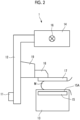
- Fig. 1 is a diagram schematically illustrating a configuration of a radiography system to which an image processing device according to a first embodiment of the present disclosure is applied
- Fig. 2 is a diagram illustrating a mammography apparatus in the radiography system as viewed from a direction of an arrow A in Fig. 1
- a radiography system 100 according to this embodiment comprises a mammography apparatus 1, a console 2, an image storage system 3, and an image processing device 4.
- the mammography apparatus 1 images a breast M, which is an object, at a plurality of radiation source positions and acquires a plurality of radiographic images, that is, a plurality of projection images, in order to perform tomosynthesis imaging on the breast to generate tomographic images.
- the mammography apparatus 1 can also perform simple imaging that irradiates the breast M with radiation at a predetermined radiation source position to acquire a two-dimensional radiographic image of the breast.
- the mammography apparatus 1 comprises an arm portion 12 that is connected to a base (not illustrated) by a rotation shaft 11.
- An imaging table 13 is attached to one end of the arm portion 12, and a radiation emitting unit 14 is attached to the other end of the arm portion 12 so as to face the imaging table 13.
- the arm portion 12 is configured such that only the end to which the radiation emitting unit 14 is attached can be rotated. Therefore, the imaging table 13 is fixed, and only the radiation emitting unit 14 can be rotated.
- the radiation detector 15 has a detection surface 15A for radiation.
- a circuit substrate including a charge amplifier that converts a charge signal read from the radiation detector 15 into a voltage signal, a correlated double sampling circuit that samples the voltage signal output from the charge amplifier, and an analog-digital (AD) conversion unit that converts the voltage signal into a digital signal is provided in the imaging table 13.
- AD analog-digital
- a radiation source 16 is accommodated in the radiation emitting unit 14.
- the radiation source 16 emits, for example, X-rays as the radiation.
- the console 2 controls the timing when the radiation source 16 emits the radiation and the radiation generation conditions of the radiation source 16, that is, the selection of target and filter materials, a tube voltage, an irradiation time, and the like.
- the arm portion 12 is provided with a compression plate 17 that is disposed above the imaging table 13 and presses and compresses the breast M, a support portion 18 that supports the compression plate 17, and a movement mechanism 19 that moves the support portion 18 in an up-down direction in Figs. 1 and 2 .
- a compression thickness is input to the console 2.
- the console 2 has a function of controlling the mammography apparatus 1 using, for example, an imaging order and various kinds of information acquired from a radiology information system (RIS) (not illustrated) or the like through a network, such as a wireless communication local area network (LAN), and instructions or the like directly issued by a radiology technician or the like.
- RIS radiology information system
- LAN wireless communication local area network
- the console 2 directs the mammography apparatus 1 to perform the tomosynthesis imaging on the breast M to acquire a plurality of projection images as described below.
- a server computer is used as the console 2.
- the image storage system 3 is a system that stores image data such as radiographic images, projection images, and tomographic images captured by the mammography apparatus 1.
- the image storage system 3 extracts an image corresponding to a request from, for example, the console 2 and the image processing device 4 from the stored images and transmits the image to a device that is the source of the request.
- a specific example of the image storage system 3 is a picture archiving and communication system (PACS).
- PACS picture archiving and communication system
- the image processing device 4 includes an image generation device and a learning device according to the present disclosure. However, in the following description, it is assumed that the image processing device represents the devices.
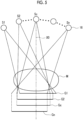
- a hardware configuration of the image processing device according to the first embodiment will be described with reference to Fig. 3 .
- the image processing device 4 is a computer, such as a workstation, a server computer, or a personal computer, and comprises a central processing unit (CPU) 21, a non-volatile storage 23, and a memory 26 as a temporary storage area.
- CPU central processing unit
- the image processing device 4 comprises a display 24, such as a liquid crystal display, an input device 25, such as a keyboard and a mouse, and a network interface (I/F) 27 that is connected to a network (not illustrated).
- the CPU 21, the storage 23, the display 24, the input device 25, the memory 26, and the network I/F 27 are connected to a bus 28.
- the CPU 21 is an example of a processor according to the present disclosure.
- the storage 23 is implemented by, for example, a hard disk drive (HDD), a solid state drive (SSD), and a flash memory.
- the storage 23 as a storage medium stores an image generation program 22A, a learning program 22B, and an image processing program 22C which are installed in the image processing device 4.
- the CPU 21 reads the image generation program 22A, the learning program 22B, and the image processing program 22C from the storage 23, expands the programs in the memory 26, and executes the expanded image generation program 22A, learning program 22B, and image processing program 22C.
- the image generation program 22A, the learning program 22B, and the image processing program 22C are stored in a storage device of a server computer connected to the network or a network storage so as to be accessed from the outside and are downloaded and installed in the computer constituting the image processing device 4 on demand.
- the programs are recorded on a recording medium, such as a digital versatile disc (DVD) or a compact disc read only memory (CD-ROM), are distributed, and are installed in the computer constituting the image processing device 4 from the recording medium.
- Fig. 4 is a diagram illustrating the functional configuration of the image processing device according to the first embodiment.
- the image processing device 4 comprises an image acquisition unit 31, a combination unit 32, a reconstruction unit 33, a training data generation unit 34, a learning unit 35, a detection unit 36, a display control unit 37, and a communication unit 38.
- the CPU 21 executes the image generation program 22A, the learning program 22B, and the image processing program 22C such that the image processing device 4 functions as the image acquisition unit 31, the combination unit 32, the reconstruction unit 33, the training data generation unit 34, the learning unit 35, the detection unit 36, the display control unit 37, and the communication unit 38.
- a learning model 36A which will be described later, is applied to the detection unit 36.
- the image acquisition unit 31, the combination unit 32, the reconstruction unit 33, the training data generation unit 34, the display control unit 37, and the communication unit 38 constitute the image generation device according to the first embodiment.
- the image acquisition unit 31 and the learning unit 35 constitute the learning device according to the first embodiment.
- the image acquisition unit 31, the detection unit 36, and the display control unit 37 constitute the image processing device according to the first embodiment.
- the image acquisition unit 31 acquires a plurality of projection images acquired by the tomosynthesis imaging performed by the mammography apparatus 1 under the control of the console 2. In addition, the image acquisition unit 31 acquires a lesion image of a simulated lesion schematically indicating a lesion included in the breast M. The image acquisition unit 31 acquires the projection image from the console 2 or the image storage system 3 through the network I/F 27. Further, the image acquisition unit 31 acquires the lesion image from the image storage system 3 through the network I/F 27. Furthermore, the image acquisition unit 31 acquires the training data, which has been generated as described below and stored in the image storage system 3, through the network I/F 27 in order to train a learning model which will be described below. Moreover, the image acquisition unit 31 acquires a target image, from which a lesion is to be detected as described below, from the image storage system 3 through the network I/F 27.
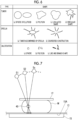
- Fig. 5 is a diagram illustrating the acquisition of the projection images Gi.
- the radiation source 16 is moved to each of radiation source positions S1, S2, ⁇ , and Sn.
- the radiation source 16 is driven at each radiation source position to irradiate the breast M with radiation.
- the radiation detector 15 detects the X-rays transmitted through the breast M to acquire projection images G1, G2, ⁇ , and Gn corresponding to the radiation source positions S1 to Sn, respectively.
- the breast M is irradiated with the same dose of radiation.
- the projection image Gi is referred to as a first projection image.
- a radiation source position Sc is a radiation source position where an optical axis X0 of the radiation emitted from the radiation source 16 is orthogonal to the detection surface 15A of the radiation detector 15. It is assumed that the radiation source position Sc is referred to as a reference radiation source position Sc.
- the combination unit 32 combines the lesion image of the simulated lesion with a plurality of first projection images Gi on the basis of a geometrical relationship between a plurality of radiation source positions in a case in which the mammography apparatus 1 performs the tomosynthesis imaging and the position of the lesion disposed at a predetermined position in the breast M to derive a plurality of second projection images.
- examples of the type of lesion in the breast M include a tumor, a spicula, and a calcification.
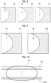
- Fig. 6 is a diagram illustrating lesion images of simulated lesions for various lesions.
- an image similar to the shape of an actual lesion is prepared as the lesion image of the simulated lesion.
- the images of a sphere, an ellipsoid, a polygon, a lobulated shape, and an irregular shape are prepared as the lesion images of the tumors.
- the images of a tumor accompanied by a spicula and a disordered construction are prepared as the lesion images of the spiculae.
- the disordered construction indicates a state without a tumor.
- the images of a sphere, a polygon, a line, and a lobulated shape are prepared as the lesion images of the calcifications.
- the lesion image of the simulated lesion may be obtained by performing radiography on the breast including the actual lesion or may be artificially generated by computer graphics or the like.
- the lesion image generated by computer graphics is used.
- the combination unit 32 derives the combination position of the lesion image with the first projection image Gi on the basis of the geometrical relationship between a plurality of radiation source positions in a case in which the mammography apparatus 1 performs the tomosynthesis imaging and the position of the lesion virtually disposed in the breast M.
- Fig. 7 is a diagram illustrating the derivation of the combination position of the lesion image in the first embodiment. As illustrated in Fig. 7 , it is assumed that a simulated lesion 40 is virtually disposed at a predetermined position in the breast M. As illustrated in Fig.
- the detection surface 15A of the radiation detector 15 is irradiated with the radiation which has been emitted at each of the radiation source positions S 1 to Sn (only S1, S2, and Sc are illustrated in Fig. 7 ) and transmitted through the simulated lesion 40 in the breast M.
- a position on the detection surface 15A of the radiation detector 15 which is irradiated with the radiation transmitted through the simulated lesion 40 differs depending on the radiation source position. Therefore, as illustrated in Fig. 8 , the position of a lesion image 42 of the simulated lesion 40 included in the first projection images G1, G2, and Gc acquired at the radiation source positions S1, S2, and Sc differs depending on the radiation source position.
- the combination unit 32 derives the combination position of the lesion image 42 with the first projection image Gi from the geometrical relationship among each of the radiation source positions S1 to Sn, the position of the simulated lesion 40 disposed in the breast M, and the position of the detection surface 15A of the radiation detector 15 in a case in which the simulated lesion 40 is virtually disposed in the breast M and the tomosynthesis imaging is performed.
- the radiation emitted from the radiation source 16 in a case in which the tomosynthesis imaging is performed is transmitted through the air between the radiation source 16 and the compression plate 17, the compression plate 17, the breast M, and a top plate 13A of the imaging table 13 and is emitted to the radiation detector 15. Therefore, the radiation emitted from the radiation source 16 is attenuated by the air, the compression plate 17, the breast M, and the top plate 13A, is emitted to the radiation detector 15, and is detected as the first projection image Gi.
- the radiation is transmitted through the air on the compression plate 17, the compression plate 17, the simulated lesion 40, and the top plate 13A of the imaging table 13 and is emitted to the radiation detector 15.
- the combination unit 32 derives a radiation attenuation coefficient indicating the attenuation of the radiation transmitted through the simulated lesion 40 and combines the lesion image 42 of the simulated lesion 40 at the combination position of the first projection image Gi on the basis of the radiation attenuation coefficient to derive a second projection image CGi.
- the derivation of the radiation attenuation coefficient of the simulated lesion 40 will be described.
- the radiation generation conditions that is, a target, a filter, and a tube voltage
- the combination unit 32 acquires an irradiation spectrum P0 of the radiation in a case in which the first projection image Gi is acquired from the radiation generation conditions.
- a table that defines the relationship between various radiation generation conditions and the irradiation spectrum P0 is prepared in advance and stored in the storage 23. The combination unit 32 acquires the irradiation spectrum P0 of the radiation in a case in which the first projection image Gi is acquired from the radiation generation conditions acquired from the console 2 with reference to the table stored in the storage 23.
- the attenuation of the radiation similarly occurs at any radiation source position Si. Therefore, in this embodiment, hereinafter, it is assumed that the radiation attenuation coefficient of the simulated lesion 40 is derived on the basis of the reference radiation source position Sc.
- the present disclosure is not limited thereto.
- the combination unit 32 derives the path length of the radiation, which has been emitted at the reference radiation source position Sc and incident on the simulated lesion 40, through the simulated lesion 40 as a thickness t1 of the simulated lesion 40.
- the combination unit 32 derives an irradiation spectrum P1 after the radiation is transmitted through the simulated lesion 40 from the irradiation spectrum P0, the radiation attenuation coefficient ⁇ 1 of the simulated lesion 40 for each radiation energy level, and the thickness t1 of the simulated lesion 40, using the following Expression (1).
- P 1 P 0 ⁇ exp ⁇ ⁇ 1 ⁇ t 1
- the combination unit 32 derives a radiation attenuation coefficient ⁇ m of the simulated lesion 40 over the entire energy range of the radiation from the radiation spectrum P0 and the radiation spectrum P1 for each radiation energy level using the following Expression (2).
- ⁇ m ⁇ Ln ⁇ P 1 ⁇ P 0 / t 1
- the combination unit 32 combines the lesion image 42 at the combination position of the first projection image Gi derived as described above, using the radiation attenuation coefficient ⁇ m of the simulated lesion 40 derived as described above, to derive the second projection image CGi.
- the pixel value of the projection image CGi at the combination position (x, y) is derived using the following Expression (3) to derive the second projection image CGi.
- G(x, y) is a combination position in the first projection image Gi
- CG(x, y) is a combination position in the second projection image CGi
- l(x, y) is the transmission length of the radiation transmitted through the simulated lesion 40 at the combination position (x, y).
- CG x , y G x , y ⁇ ⁇ m ⁇ 1 x , y
- Fig. 9 is a diagram illustrating the first projection image Gi and the second projection image CGi. As illustrated in Fig. 9 , in the second projection image CGi, the lesion image 42 of the simulated lesion 40 is included at a combination position 41 in the first projection image Gi.
- the combination unit 32 generates the second projection images CGi including the lesion images of various types of simulated lesions having various shapes as illustrated in Fig. 6 .
- a known back projection method such as a simple back projection method or a filtered back projection method
- a three-dimensional coordinate position in a three-dimensional space including the breast M is set, pixel values at corresponding pixel positions in the plurality of second projection images CGi are reconstructed for the set three-dimensional coordinate position, and pixel values at the coordinate positions are calculated.
- a three-dimensional image of the breast M is constructed by the plurality of tomographic images Daj generated by the reconstruction.
- the generated tomographic images Daj include a tomographic image 43 of the simulated lesion 40 virtually disposed in the breast M in a case in which the second projection images CGi are generated.
- the tomographic image 43 of the simulated lesion 40 is included in the tomographic images Da2, Da3, and Da4.
- the tomographic image Daj including the simulated lesion 40 is referred to as an abnormal image. Further, in the following description, it is assumed that the abnormal image is denoted by reference letters Daj.
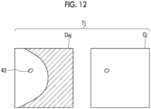
- the training data generation unit 34 generates training data Tj including the abnormal images (that is, the tomographic images Daj including the tomographic image 43 of the simulated lesion 40) generated as described above and data (hereinafter, referred to as correct answer data) indicating the position of the tomographic image 43 included in each of the abnormal images Daj.
- Fig. 12 is a diagram schematically illustrating the training data generated in the first embodiment. As illustrated in Fig. 12 , the training data Tj consists of the abnormal image Daj including the tomographic image 43 of the simulated lesion 40 and correct answer data Cj indicating the position of the tomographic image 43 of the simulated lesion 40 in the abnormal image Daj. In addition, the training data is generated for each abnormal image Daj.
- the training data Tj generated by the training data generation unit 34 is stored in the storage 23.
- the display control unit 37 may display the generated abnormal image Daj on the display 24. Further, the communication unit 38 transmits the training data Tj to the image storage system 3. The image storage system 3 stores the received training data Tj.
- the learning unit 35 constructs the learning model 36A of the detection unit 36 by training a machine learning model, using the training data Tj for the abnormal image as first training data and training data for a medical image which does not include the lesion as second training data, so as to discriminate a lesion region in the input target image.
- a plurality of first training data items and a plurality of second training data items are prepared. Therefore, in a case in which the machine learning model is trained, the image acquisition unit 31 acquires the plurality of first training data items and the plurality of second training data items from the storage 23 or the image storage system 3.
- An example of the machine learning model for constructing the learning model 36A is a neural network model.
- the neural network model include a simple perceptron, a multilayer perceptron, a deep neural network, a convolutional neural network, a deep belief network, a recurrent neural network, and a stochastic neural network.
- the convolutional neural network is used as the machine learning model for constructing the learning model 36A.
- the learning model 36A is constructed by training the machine learning model so as to output the probability (likelihood) that each pixel of the abnormal image Daj will be the lesion region in a case in which the abnormal image Daj included in the training data is input.
- a region consisting of the pixels having the probability which has been output from the learning model 36A and is equal to or greater than a predetermined threshold value is the lesion region.
- the learning unit 35 inputs the abnormal image to the machine learning model and outputs the probability that each pixel of the abnormal image will be the lesion region. Then, the difference between the region consisting of the pixels having the probability which has been output from the machine learning model and is equal to or greater than the predetermined threshold value and the region indicated by the correct answer data included in the training data is derived as a loss.
- the machine learning model is trained on the basis of the loss. Specifically, for example, a kernel coefficient in the convolutional neural network and a weight for the connection of neural networks are derived so as to reduce the loss.
- the learning unit 35 repeats the training until the loss is equal to or less than a predetermined threshold value. Therefore, the learning model 36A is constructed such that the probability higher than the predetermined threshold value is output for the lesion region included in the input target image to extract the lesion region included in the input target image.
- the learning model 36A constructed by the learning unit 35 is applied to the detection unit 36.
- the detection unit 36 directs the learning model 36A to detect the lesion region included in the target image, thereby detecting the lesion region.
- the image acquisition unit 31 acquires the projection image (referred to as a target projection image), which is to be the target image, from the mammography apparatus 1 or the image storage system 3. Then, the reconstruction unit 33 reconstructs the target projection image to generate a target tomographic image.
- the detection unit 36 detects the lesion region from the target tomographic image.
- the console 2 of the mammography apparatus 1 may generate the target tomographic image from the target projection image.
- the image acquisition unit 31 acquires the target tomographic image from the console 2. Further, in a case in which the target tomographic image generated from the target projection image is stored in the image storage system 3, the image acquisition unit 31 may acquire the target tomographic image from the image storage system 3.
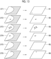
- Fig. 13 is a diagram illustrating the target tomographic images and the detection result of the lesion region.
- the detection unit 36 detects the lesion region from six target tomographic images DT1 to DT6 and outputs detection results R1 to R6.
- the display control unit 37 displays the target tomographic image on the display 24 such that the lesion region detected from the target tomographic image by the detection unit 36 is highlighted.
- Fig. 14 is a diagram illustrating a display screen for the detection result of the target tomographic image in the first embodiment. As illustrated in Fig. 14 , the first target tomographic image DT1 among the six target tomographic images DT1 to DT6 illustrated in Fig. 13 is displayed on a display screen 50. The displayed target tomographic image can be switched by an operation through the input device 25.
- the display control unit 37 surrounds a lesion region 52 included in the target tomographic image DT1 with a rectangular frame 53 to highlight the lesion region 52 in the target tomographic image DT1.
- the rectangular frame 53 is illustrated in white in Fig. 14 .
- the rectangular frame 53 may be colored.
- a mark such as an arrow or an asterisk, may be given in the vicinity of the lesion region to highlight the lesion region.
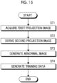
- Fig. 15 is a flowchart illustrating an image generation process performed in the first embodiment.
- the image acquisition unit 31 acquires a plurality of first projection images Gi (Step ST1).
- the combination unit 32 combines the lesion image 42 with the first projection images Gi on the basis of the geometrical relationship between a plurality of radiation source positions in a case in which the mammography apparatus 1 performs the tomosynthesis imaging and the position of the simulated lesion virtually disposed in the breast M to derive a plurality of second projection images CGi (Step ST2).
- the reconstruction unit 33 reconstructs the plurality of second projection images CGi to generate, as the abnormal images Daj, the tomographic images which include the tomographic image 43 of the simulated lesion 40 and in which a desired tomographic plane of the breast M has been highlighted (abnormal image generation: Step ST3).
- the training data generation unit 34 generates the training data Tj including the abnormal images Daj generated as described above and the correct answer data Cj indicating the position of the tomographic image 43 of the simulated lesion 40 included in each of the abnormal images Daj (Step ST4).
- the generated training data Tj is stored in the storage 23 and is further transmitted to the image storage system 3 by the communication unit 38.
- Fig. 16 is a flowchart illustrating the learning process performed in the first embodiment.
- the image acquisition unit 31 acquires the first training data and the second training data (Step ST1 1).
- the learning unit 35 inputs the first training data and the second training data to the machine learning model for constructing the learning model 36A of the detection unit 36 to acquire the extraction result of the lesion region, trains the machine learning model using the loss based on a difference from the correct answer data (Step ST12), and returns to Step ST11.
- the learning unit 35 repeats the processes in Steps ST11 and ST12 until the loss reaches a predetermined threshold value and ends the training of the machine learning model.
- the learning model 36A is constructed.
- the learning unit 35 may repeat the training a predetermined number of times and end the training.
- Fig. 17 is a flowchart illustrating the detection process performed in the first embodiment.
- the image acquisition unit 31 acquires the target image (target tomographic image DTj) to be detected (Step ST21), and the detection unit 36 detects the lesion region from the target image (Step ST22). Then, the display control unit 37 displays the target image in which the lesion region has been highlighted on the display 24 (Step ST23). Then, the process ends.
- the tomographic images Daj including the tomographic image 43 of the simulated lesion 40 are generated as the abnormal images, using the second projection images CGi generated by combining the lesion image 42 of the simulated lesion 40 with the first projection images Gi. Therefore, the tomographic images including various types of lesions at various positions can be generated as the abnormal images by changing the type of simulated lesion 40 in various ways or by changing the position where the simulated lesion 40 is provided in various ways. As a result, it is possible to prepare a sufficient number of abnormal images and sufficient variations of abnormal images in order to train the machine learning model for constructing the learning model 36A.
- the learning model 36Afor discriminating the lesion region from the input target image is constructed by machine learning, using the first training data consisting of the abnormal image and data including information indicating the position of the lesion image in the abnormal image.
- the learning model 36A it is possible to prepare a sufficient number of abnormal images, sufficient variations of abnormal images, and the first training data in order to train the machine learning model for constructing the learning model 36A. Therefore, according to this embodiment, it is possible to construct the learning model 36A having high lesion detection accuracy.
- the second projection images CGi are derived on the basis of the radiation attenuation coefficient ⁇ m of the simulated lesion 40, it is possible to acquire the second projection images CGi as in a case in which the breast M including the lesion is actually imaged. Therefore, it is possible to construct the learning model 36A having high lesion detection accuracy.
- the configuration of an image processing device according to the second embodiment is the same as the configuration of the image processing device 4 according to the first embodiment except only the process to be performed. Therefore, the detailed description of the device will not be repeated here.
- the lesion image 42 of the simulated lesion 40 is combined with the first projection image Gi acquired by the tomosynthesis imaging to generate the second projection image CGi, and the tomographic image is generated as the abnormal image from the second projection image CGi.
- the second embodiment differs from the first embodiment in that an image obtained by combining the lesion image 42 of the simulated lesion 40 with a radiographic image acquired by simple imaging is generated as the abnormal image.
- the image processing device according to the second embodiment does not require the reconstruction unit 33 according to the first embodiment. Therefore, the image processing device according to the second embodiment may not comprise the reconstruction unit 33.
- the mammography apparatus 1 performs the simple imaging which irradiates the breast M with radiation only at the reference radiation source position Sc to acquire a radiographic image H0 of the breast M.
- the image acquisition unit 31 acquires the radiographic image H0 of the breast M obtained by the simple imaging.
- the combination unit 32 combines the lesion image 42 of the simulated lesion 40 at a combination position of the radiographic image H0.
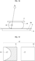
- Fig. 18 is a diagram illustrating the combination position of the lesion image 42 of the simulated lesion 40 in the second embodiment.
- the breast M is imaged only at the reference radiation source position Sc. Therefore, the combination unit 32 derives the combination position of the lesion image 42 in the radiographic image H0 on the basis of a geometrical relationship among the reference radiation source position Sc, the position of the simulated lesion 40 virtually disposed in the breast M, and the position of the detection surface 15A of the radiation detector 15.
- the combination unit 32 performs the radiation attenuation simulation to derive the radiation attenuation coefficient ⁇ m of the simulated lesion 40 and combines the lesion image 42 at the combination position in the radiographic image H0 derived as described above, using the radiation attenuation coefficient ⁇ m, to generate an abnormal image H1.
- the training data generation unit 34 generates training data HT including the abnormal image H1 generated as described above and data (correct answer data) indicating the position of the lesion image included in the abnormal image H1.
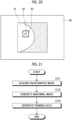
- Fig. 19 is a diagram schematically illustrating the training data generated in the second embodiment. As illustrated in Fig. 19 , the training data HT consists of the abnormal image H1 including the lesion image 44 of the simulated lesion 40 and correct answer data HC indicating the position of the lesion image 44 of the simulated lesion 40 in the abnormal image H1.
- the training data HT generated by the training data generation unit 34 is stored in the storage 23.
- the display control unit 37 may be configured to display the generated abnormal image H1 on the display 24.
- the communication unit 38 transmits the training data HT to the image storage system 3.
- the image storage system 3 stores the received training data HT.
- the learning unit 35 trains the machine learning model so as to discriminate the lesion region in the input target image acquired by the simple imaging, using the training data HT for the abnormal image H1 as the first training data and training data for the medical image, which does not include the lesion, as the second training data, to construct the learning model 36A of the detection unit 36.
- a plurality of first training data items and a plurality of second training data items are prepared. Therefore, in a case in which the machine learning model is trained, the image acquisition unit 31 acquires the plurality of first training data items and the plurality of second training data items from the storage 23 or the image storage system 3.
- the learning process performed by the learning unit 35 is the same as that in the first embodiment except that the training data is a tomographic image, the detailed description thereof will not be repeated here.
- the detection unit 36 directs the learning model 36A to detect the lesion region included in the target image, thereby detecting the lesion region.
- Fig. 20 is a diagram illustrating a display screen for the detection result of the target image in the second embodiment.
- a target image 61 is displayed on a display screen 60.
- the display control unit 37 surrounds a lesion region 62 included in the target image 61 with a rectangular frame 63 to highlight the lesion region 62 in the target image 61.
- Fig. 21 is a flowchart illustrating an image generation process performed in the second embodiment.
- the image acquisition unit 31 acquires the radiographic image H0 for generating an abnormal image (Step ST31).
- the combination unit 32 combines the lesion image with the radiographic image H0 on the basis of the geometrical relationship between the radiation source position in a case in which the mammography apparatus 1 performs imaging and the position of the simulated lesion virtually disposed in the breast M to generate the abnormal image H1 (Step ST32).
- the training data generation unit 34 generates training data including the abnormal image H1 and correct answer data indicating the position of the lesion image included in the abnormal image H1 (Step ST33). Then, the process ends.
- the generated training data is stored in the storage 23 and is further transmitted to the image storage system 3 by the communication unit 38.
- the learning process in the second embodiment is the same as that in the first embodiment except that the training data consists of the abnormal image H1 and the correct answer data.
- the lesion detection process in the second embodiment is the same as that in the first embodiment except that the target image is a radiographic image acquired by the simple imaging. Therefore, the detailed description of the learning process and the lesion detection process in the second embodiment will not be repeated.
- the lesion image 42 of the simulated lesion 40 is combined with a plurality of tomographic images to generate the abnormal images Daj including the tomographic image 43 of the simulated lesion 40. Therefore, a composite two-dimensional image may be generated using a plurality of abnormal images Daj.
- the composite two-dimensional image is a pseudo two-dimensional image equivalent to a simple two-dimensional image obtained by combining a plurality of tomographic images including the abnormal image using, for example, an addition method, an averaging method, a maximum intensity projection method, or a minimum intensity projection method (see JP2014-128716A ).
- Fig. 22 is a diagram illustrating the generation of the composite two-dimensional image.
- the combination unit 32 may generate the composite two-dimensional image, or a composite two-dimensional image generation unit for generating the composite two-dimensional image may be provided and generate the composite two-dimensional image.
- the combination unit 32 generates a composite two-dimensional image GG0 by combining the pixel values of the corresponding pixel positions of a plurality of tomographic images including the abnormal images along a viewing direction from the reference radiation source position Sc to the radiation detector 15, that is, along the optical axis X0 illustrated in Fig. 5 in a state in which a plurality of abnormal images Daj are stacked.
- the training data generation unit 34 generates training data from the composite two-dimensional image GG0 and data indicating the position of the lesion image of the simulated lesion 40 included in the composite two-dimensional image GG0.
- the learning unit 35 constructs the learning model 36A of the detection unit 36 by training the machine learning model using the training data so as to detect the lesion included in the composite two-dimensional image in a case in which the composite two-dimensional image is input.
- the use of the learning model 36A constructed in this way makes it possible to detect the lesion from the target image which is the composite two-dimensional image in a case in which the composite two-dimensional image is input as the target image to the detection unit 36.
- a method for generating the composite two-dimensional image is not limited to the above-mentioned method.
- only the tomographic images included in the abnormal images Daj may be combined with any tomographic image prepared in advance to generate the composite two-dimensional image.
- only the tomographic images included in the abnormal images Daj may be averaged and combined to generate the composite two-dimensional image.
- the radiation in the above-described embodiments is not particularly limited.
- ⁇ -rays or ⁇ -rays can be applied in addition to the X-rays.
- the object is the breast M.
- the object is not limited thereto.
- any part of the human body such as the heart, the liver, the brain, and the limbs, can be used as the object.
- the simulated lesion corresponding to the type of object may be prepared.
- the learning model 36A of the detection unit 36 which detects a lesion corresponding to the object is prepared and trained using the generated training data including the abnormal image. The detection unit 36 detects the lesion corresponding to the object.
- the following various processors can be used as a hardware structure of processing units performing various processes, such as the image acquisition unit 31, the combination unit 32, the reconstruction unit 33, the training data generation unit 34, the learning unit 35, the detection unit 36, the display control unit 37, and the communication unit 38.
- the various processors include, for example, a CPU which is a general-purpose processor executing software (program) to function as various processing units as described above, a programmable logic device (PLD), such as a field programmable gate array (FPGA), which is a processor whose circuit configuration can be changed after manufacture, and a dedicated electric circuit, such as an application specific integrated circuit (ASIC), which is a processor having a dedicated circuit configuration designed to perform a specific process.
- PLD programmable logic device
- FPGA field programmable gate array
- ASIC application specific integrated circuit
- One processing unit may be configured by one of the various processors or a combination of two or more processors of the same type or different types (for example, a combination of a plurality of FPGAs or a combination of a CPU and an FPGA).
- a plurality of processing units may be configured by one processor.
- a first example of the configuration in which a plurality of processing units are configured by one processor is an aspect in which one processor is configured by a combination of one or more CPUs and software and functions as a plurality of processing units.
- a representative example of this aspect is a client computer or a server computer.
- a second example of the configuration is an aspect in which a processor that implements the functions of the entire system including a plurality of processing units using one integrated circuit (IC) chip is used.
- IC integrated circuit
- a representative example of this aspect is a system-on-chip (SoC).
- SoC system-on-chip
- various processing units are configured by using one or more of the various processors as a hardware structure.
- an electric circuit obtained by combining circuit elements, such as semiconductor elements, can be used as the hardware structure of the various processors.
Landscapes
- Engineering & Computer Science (AREA)
- Health & Medical Sciences (AREA)
- Life Sciences & Earth Sciences (AREA)
- Physics & Mathematics (AREA)
- Medical Informatics (AREA)
- Theoretical Computer Science (AREA)
- General Physics & Mathematics (AREA)
- General Health & Medical Sciences (AREA)
- Nuclear Medicine, Radiotherapy & Molecular Imaging (AREA)
- Radiology & Medical Imaging (AREA)
- Molecular Biology (AREA)
- Biomedical Technology (AREA)
- Biophysics (AREA)
- Heart & Thoracic Surgery (AREA)
- Optics & Photonics (AREA)
- Pathology (AREA)
- High Energy & Nuclear Physics (AREA)
- Surgery (AREA)
- Animal Behavior & Ethology (AREA)
- Public Health (AREA)
- Veterinary Medicine (AREA)
- Computer Vision & Pattern Recognition (AREA)
- Mathematical Physics (AREA)
- Quality & Reliability (AREA)
- Data Mining & Analysis (AREA)
- Physiology (AREA)
- Evolutionary Computation (AREA)
- Computing Systems (AREA)
- General Engineering & Computer Science (AREA)
- Artificial Intelligence (AREA)
- Software Systems (AREA)
- Computational Linguistics (AREA)
- Dentistry (AREA)
- Oral & Maxillofacial Surgery (AREA)
- Algebra (AREA)
- Mathematical Analysis (AREA)
- Mathematical Optimization (AREA)
- Pure & Applied Mathematics (AREA)
- Apparatus For Radiation Diagnosis (AREA)
Applications Claiming Priority (2)
| Application Number | Priority Date | Filing Date | Title |
|---|---|---|---|
| JP2020044697 | 2020-03-13 | ||
| PCT/JP2021/008162 WO2021182229A1 (ja) | 2020-03-13 | 2021-03-03 | 画像生成装置およびプログラム、学習装置およびプログラム、並びに画像処理装置およびプログラム |
Publications (3)
| Publication Number | Publication Date |
|---|---|
| EP4119055A1 EP4119055A1 (en) | 2023-01-18 |
| EP4119055A4 EP4119055A4 (en) | 2023-08-09 |
| EP4119055B1 true EP4119055B1 (en) | 2024-10-30 |
Family
ID=77670717
Family Applications (1)
| Application Number | Title | Priority Date | Filing Date |
|---|---|---|---|
| EP21766927.4A Active EP4119055B1 (en) | 2020-03-13 | 2021-03-03 | Image generation device and program, learning device and program, and image processing device and program |
Country Status (4)
| Country | Link |
|---|---|
| US (1) | US12417565B2 (enExample) |
| EP (1) | EP4119055B1 (enExample) |
| JP (1) | JP7513697B2 (enExample) |
| WO (1) | WO2021182229A1 (enExample) |
Families Citing this family (3)
| Publication number | Priority date | Publication date | Assignee | Title |
|---|---|---|---|---|
| JP7413216B2 (ja) * | 2020-09-15 | 2024-01-15 | 富士フイルム株式会社 | 学習装置、方法およびプログラム、学習済みモデル、並びに放射線画像処理装置、方法およびプログラム |
| CN116128320B (zh) * | 2023-01-04 | 2023-08-08 | 杭州有泰信息技术有限公司 | 电网输变电可视化管控方法及平台 |
| WO2025150130A1 (ja) * | 2024-01-11 | 2025-07-17 | 富士通株式会社 | 病変識別方法および病変識別プログラム |
Family Cites Families (36)
| Publication number | Priority date | Publication date | Assignee | Title |
|---|---|---|---|---|
| US7831296B2 (en) | 2002-11-27 | 2010-11-09 | Hologic, Inc. | X-ray mammography with tomosynthesis |
| US8571289B2 (en) | 2002-11-27 | 2013-10-29 | Hologic, Inc. | System and method for generating a 2D image from a tomosynthesis data set |
| US7123684B2 (en) | 2002-11-27 | 2006-10-17 | Hologic, Inc. | Full field mammography with tissue exposure control, tomosynthesis, and dynamic field of view processing |
| US8565372B2 (en) | 2003-11-26 | 2013-10-22 | Hologic, Inc | System and method for low dose tomosynthesis |
| US7577282B2 (en) | 2002-11-27 | 2009-08-18 | Hologic, Inc. | Image handling and display in X-ray mammography and tomosynthesis |
| US7616801B2 (en) | 2002-11-27 | 2009-11-10 | Hologic, Inc. | Image handling and display in x-ray mammography and tomosynthesis |
| US10638994B2 (en) | 2002-11-27 | 2020-05-05 | Hologic, Inc. | X-ray mammography with tomosynthesis |
| US7760924B2 (en) | 2002-11-27 | 2010-07-20 | Hologic, Inc. | System and method for generating a 2D image from a tomosynthesis data set |
| US8768026B2 (en) | 2003-11-26 | 2014-07-01 | Hologic, Inc. | X-ray imaging with x-ray markers that provide adjunct information but preserve image quality |
| US7702142B2 (en) | 2004-11-15 | 2010-04-20 | Hologic, Inc. | Matching geometry generation and display of mammograms and tomosynthesis images |
| US7869563B2 (en) | 2004-11-26 | 2011-01-11 | Hologic, Inc. | Integrated multi-mode mammography/tomosynthesis x-ray system and method |
| US10008184B2 (en) | 2005-11-10 | 2018-06-26 | Hologic, Inc. | System and method for generating a 2D image using mammography and/or tomosynthesis image data |
| US7903857B2 (en) | 2006-04-17 | 2011-03-08 | Siemens Medical Solutions Usa, Inc. | Robust click-point linking with geometric configuration context: interactive localized registration approach |
| JP2008048880A (ja) * | 2006-08-24 | 2008-03-06 | Ge Medical Systems Global Technology Co Llc | 画像作成方法 |
| JP4895204B2 (ja) * | 2007-03-22 | 2012-03-14 | 富士フイルム株式会社 | 画像成分分離装置、方法、およびプログラム、ならびに、正常画像生成装置、方法、およびプログラム |
| JP5125500B2 (ja) * | 2007-12-29 | 2013-01-23 | オムロン株式会社 | X線断層撮影のシミュレーション方法およびシミュレーション用のプログラム |
| JP2014534042A (ja) | 2011-11-27 | 2014-12-18 | ホロジック, インコーポレイテッドHologic, Inc. | マンモグラフィーおよび/またはトモシンセシス画像データを使用して2d画像を生成するためのシステムおよび方法 |
| US8983156B2 (en) | 2012-11-23 | 2015-03-17 | Icad, Inc. | System and method for improving workflow efficiences in reading tomosynthesis medical image data |
| GB2533632B (en) * | 2014-12-24 | 2018-01-03 | Gen Electric | Method and system for obtaining low dose tomosynthesis and material decomposition images |
| US9792703B2 (en) | 2015-07-06 | 2017-10-17 | Siemens Healthcare Gmbh | Generating a synthetic two-dimensional mammogram |
| WO2017116512A1 (en) * | 2015-12-28 | 2017-07-06 | Metritrack, Inc. | System and method for the coregistration of medical image data |
| JP6566887B2 (ja) * | 2016-02-16 | 2019-08-28 | 富士フイルム株式会社 | 放射線画像処理装置、方法およびプログラム |
| US20170337682A1 (en) * | 2016-05-18 | 2017-11-23 | Siemens Healthcare Gmbh | Method and System for Image Registration Using an Intelligent Artificial Agent |
| EP3254623B1 (en) * | 2016-06-09 | 2020-09-16 | Agfa Nv | Method and system for correcting geometric misalignment during image reconstruction in chest tomosynthesis |
| JP6755130B2 (ja) * | 2016-06-21 | 2020-09-16 | 株式会社日立製作所 | 画像処理装置、及び方法 |
| US10165997B2 (en) * | 2016-07-05 | 2019-01-01 | Siemens Healthcare Gmbh | System for acquiring a three-dimensional image of arteries and veins |
| CN109890293B (zh) * | 2016-10-28 | 2023-06-13 | 苏尔吉维索公司 | 用于确定x射线成像系统的轨迹的方法和系统 |
| EP3400878B1 (en) * | 2017-05-10 | 2020-03-25 | Esaote S.p.A. | Method for postural independent location of targets in diagnostic imagines acquired by multimodal acquisitions and system for carrying out the said method |
| JP6824133B2 (ja) * | 2017-09-28 | 2021-02-03 | 富士フイルム株式会社 | 画像処理装置、画像処理方法、及び画像処理プログラム |
| JP6917913B2 (ja) * | 2018-01-17 | 2021-08-11 | 富士フイルム株式会社 | 画像処理装置、画像処理方法、及び画像処理プログラム |
| JP7113447B2 (ja) * | 2018-03-12 | 2022-08-05 | 東芝エネルギーシステムズ株式会社 | 医用画像処理装置、治療システム、および医用画像処理プログラム |
| CN108986182B (zh) * | 2018-07-10 | 2022-11-25 | 上海联影医疗科技股份有限公司 | 一种重建ct图像的方法、系统及存储介质 |
| JP7179521B2 (ja) * | 2018-08-02 | 2022-11-29 | キヤノンメディカルシステムズ株式会社 | 医用画像処理装置、画像生成方法、及び画像生成プログラム |
| JP7482860B2 (ja) * | 2018-09-28 | 2024-05-14 | ホロジック, インコーポレイテッド | 高密度要素抑制による合成乳房組織画像発生のためのシステムおよび方法 |
| US11331162B2 (en) * | 2020-01-13 | 2022-05-17 | Imaging For Women, L.L.C. | Surface markers for 3D supine automated ultrasound imaging and use thereof |
| US11564645B2 (en) * | 2020-02-25 | 2023-01-31 | GE Precision Healthcare LLC | Methods and systems for digital mammography imaging |
-
2021
- 2021-03-03 JP JP2022505970A patent/JP7513697B2/ja active Active
- 2021-03-03 EP EP21766927.4A patent/EP4119055B1/en active Active
- 2021-03-03 WO PCT/JP2021/008162 patent/WO2021182229A1/ja not_active Ceased
-
2022
- 2022-08-09 US US17/818,362 patent/US12417565B2/en active Active
Also Published As
| Publication number | Publication date |
|---|---|
| US12417565B2 (en) | 2025-09-16 |
| WO2021182229A1 (ja) | 2021-09-16 |
| EP4119055A4 (en) | 2023-08-09 |
| JPWO2021182229A1 (enExample) | 2021-09-16 |
| US20220383564A1 (en) | 2022-12-01 |
| EP4119055A1 (en) | 2023-01-18 |
| JP7513697B2 (ja) | 2024-07-09 |
Similar Documents
| Publication | Publication Date | Title |
|---|---|---|
| US7142633B2 (en) | Enhanced X-ray imaging system and method | |
| JP6185061B2 (ja) | 画像表示装置、画像表示方法および画像表示プログラム | |
| US12417565B2 (en) | Image generation device, image generation program, learning device, learning program, image processing device, and image processing program | |
| KR20240013724A (ko) | 다중 펄스 x-선 소스 이동 단층합성 영상화 시스템을 사용한 인공 지능 훈련 | |
| US11587215B2 (en) | Image processing device, image processing method, image processing program, image display device, image display method, and image display program | |
| US11517280B2 (en) | Image processing apparatus, method, and program | |
| US12272055B2 (en) | Image processing device, image processing method, and image processing program | |
| US12327352B2 (en) | Image setting device, image setting method, and image setting program | |
| US20220309657A1 (en) | Image processing device, image processing method, and image processing program | |
| JP7583653B2 (ja) | 推定装置、方法およびプログラム | |
| WO2020202612A1 (ja) | 画像処理装置、方法およびプログラム | |
| JP2021019930A (ja) | 画像処理装置、方法およびプログラム | |
| US12307664B2 (en) | Image processing device, image processing method, and image processing program | |
| US12112479B2 (en) | Image processing device, image processing method, and image processing program | |
| US20230146430A1 (en) | Image processing device, image processing method, and image processing program | |
| JP7780877B2 (ja) | X線コンピュータ断層撮影装置、学習装置及び超音波診断装置 | |
| US20220343501A1 (en) | Image setting device, image setting method, and image setting program | |
| EP4528651A1 (en) | Image processing apparatus, radiography system, and program | |
| JP2025040874A (ja) | 画像処理装置、放射線画像撮影システム及びプログラム | |
| Vedantham et al. | Breast Cancer Screening: Opportunities and Challenges with Fully 3D Tomographic X-Ray Imaging | |
| US11224397B2 (en) | Imaging control device, imaging control method, and imaging control program | |
| JP2025138515A (ja) | 画像処理装置、放射線画像撮影システム及びプログラム |
Legal Events
| Date | Code | Title | Description |
|---|---|---|---|
| STAA | Information on the status of an ep patent application or granted ep patent |
Free format text: STATUS: THE INTERNATIONAL PUBLICATION HAS BEEN MADE |
|
| PUAI | Public reference made under article 153(3) epc to a published international application that has entered the european phase |
Free format text: ORIGINAL CODE: 0009012 |
|
| STAA | Information on the status of an ep patent application or granted ep patent |
Free format text: STATUS: REQUEST FOR EXAMINATION WAS MADE |
|
| 17P | Request for examination filed |
Effective date: 20220913 |
|
| AK | Designated contracting states |
Kind code of ref document: A1 Designated state(s): AL AT BE BG CH CY CZ DE DK EE ES FI FR GB GR HR HU IE IS IT LI LT LU LV MC MK MT NL NO PL PT RO RS SE SI SK SM TR |
|
| DAV | Request for validation of the european patent (deleted) | ||
| DAX | Request for extension of the european patent (deleted) | ||
| A4 | Supplementary search report drawn up and despatched |
Effective date: 20230706 |
|
| RIC1 | Information provided on ipc code assigned before grant |
Ipc: A61B 6/04 20060101ALN20230630BHEP Ipc: G06T 11/00 20060101ALI20230630BHEP Ipc: G06N 20/00 20190101ALI20230630BHEP Ipc: G06N 3/00 20230101ALI20230630BHEP Ipc: A61B 6/02 20060101ALI20230630BHEP Ipc: A61B 6/00 20060101AFI20230630BHEP |
|
| GRAP | Despatch of communication of intention to grant a patent |
Free format text: ORIGINAL CODE: EPIDOSNIGR1 |
|
| STAA | Information on the status of an ep patent application or granted ep patent |
Free format text: STATUS: GRANT OF PATENT IS INTENDED |
|
| RIC1 | Information provided on ipc code assigned before grant |
Ipc: A61B 6/04 20060101ALN20240503BHEP Ipc: G06N 3/09 20230101ALI20240503BHEP Ipc: A61B 6/50 20240101ALI20240503BHEP Ipc: G06T 11/00 20060101ALI20240503BHEP Ipc: G06N 20/00 20190101ALI20240503BHEP Ipc: G06N 3/00 20060101ALI20240503BHEP Ipc: A61B 6/02 20060101ALI20240503BHEP Ipc: A61B 6/00 20060101AFI20240503BHEP |
|
| RIC1 | Information provided on ipc code assigned before grant |
Ipc: A61B 6/04 20060101ALN20240522BHEP Ipc: G06N 3/09 20230101ALI20240522BHEP Ipc: A61B 6/50 20240101ALI20240522BHEP Ipc: G06T 11/00 20060101ALI20240522BHEP Ipc: G06N 20/00 20190101ALI20240522BHEP Ipc: G06N 3/00 20060101ALI20240522BHEP Ipc: A61B 6/02 20060101ALI20240522BHEP Ipc: A61B 6/00 20060101AFI20240522BHEP |
|
| INTG | Intention to grant announced |
Effective date: 20240610 |
|
| GRAS | Grant fee paid |
Free format text: ORIGINAL CODE: EPIDOSNIGR3 |
|
| GRAA | (expected) grant |
Free format text: ORIGINAL CODE: 0009210 |
|
| STAA | Information on the status of an ep patent application or granted ep patent |
Free format text: STATUS: THE PATENT HAS BEEN GRANTED |
|
| P01 | Opt-out of the competence of the unified patent court (upc) registered |
Free format text: CASE NUMBER: APP_52383/2024 Effective date: 20240918 |
|
| AK | Designated contracting states |
Kind code of ref document: B1 Designated state(s): AL AT BE BG CH CY CZ DE DK EE ES FI FR GB GR HR HU IE IS IT LI LT LU LV MC MK MT NL NO PL PT RO RS SE SI SK SM TR |
|
| REG | Reference to a national code |
Ref country code: GB Ref legal event code: FG4D |
|
| REG | Reference to a national code |
Ref country code: CH Ref legal event code: EP |
|
| REG | Reference to a national code |
Ref country code: IE Ref legal event code: FG4D |
|
| REG | Reference to a national code |
Ref country code: DE Ref legal event code: R096 Ref document number: 602021021069 Country of ref document: DE |
|
| REG | Reference to a national code |
Ref country code: LT Ref legal event code: MG9D |
|
| REG | Reference to a national code |
Ref country code: NL Ref legal event code: MP Effective date: 20241030 |
|
| PG25 | Lapsed in a contracting state [announced via postgrant information from national office to epo] |
Ref country code: PT Free format text: LAPSE BECAUSE OF FAILURE TO SUBMIT A TRANSLATION OF THE DESCRIPTION OR TO PAY THE FEE WITHIN THE PRESCRIBED TIME-LIMIT Effective date: 20250228 Ref country code: IS Free format text: LAPSE BECAUSE OF FAILURE TO SUBMIT A TRANSLATION OF THE DESCRIPTION OR TO PAY THE FEE WITHIN THE PRESCRIBED TIME-LIMIT Effective date: 20250228 Ref country code: HR Free format text: LAPSE BECAUSE OF FAILURE TO SUBMIT A TRANSLATION OF THE DESCRIPTION OR TO PAY THE FEE WITHIN THE PRESCRIBED TIME-LIMIT Effective date: 20241030 |
|
| PGFP | Annual fee paid to national office [announced via postgrant information from national office to epo] |
Ref country code: DE Payment date: 20250128 Year of fee payment: 5 |
|
| PG25 | Lapsed in a contracting state [announced via postgrant information from national office to epo] |
Ref country code: NL Free format text: LAPSE BECAUSE OF FAILURE TO SUBMIT A TRANSLATION OF THE DESCRIPTION OR TO PAY THE FEE WITHIN THE PRESCRIBED TIME-LIMIT Effective date: 20241030 Ref country code: FI Free format text: LAPSE BECAUSE OF FAILURE TO SUBMIT A TRANSLATION OF THE DESCRIPTION OR TO PAY THE FEE WITHIN THE PRESCRIBED TIME-LIMIT Effective date: 20241030 |
|
| REG | Reference to a national code |
Ref country code: AT Ref legal event code: MK05 Ref document number: 1736105 Country of ref document: AT Kind code of ref document: T Effective date: 20241030 |
|
| PG25 | Lapsed in a contracting state [announced via postgrant information from national office to epo] |
Ref country code: BG Free format text: LAPSE BECAUSE OF FAILURE TO SUBMIT A TRANSLATION OF THE DESCRIPTION OR TO PAY THE FEE WITHIN THE PRESCRIBED TIME-LIMIT Effective date: 20241030 |
|
| PG25 | Lapsed in a contracting state [announced via postgrant information from national office to epo] |
Ref country code: ES Free format text: LAPSE BECAUSE OF FAILURE TO SUBMIT A TRANSLATION OF THE DESCRIPTION OR TO PAY THE FEE WITHIN THE PRESCRIBED TIME-LIMIT Effective date: 20241030 |
|
| PG25 | Lapsed in a contracting state [announced via postgrant information from national office to epo] |
Ref country code: NO Free format text: LAPSE BECAUSE OF FAILURE TO SUBMIT A TRANSLATION OF THE DESCRIPTION OR TO PAY THE FEE WITHIN THE PRESCRIBED TIME-LIMIT Effective date: 20250130 |
|
| PG25 | Lapsed in a contracting state [announced via postgrant information from national office to epo] |
Ref country code: AT Free format text: LAPSE BECAUSE OF FAILURE TO SUBMIT A TRANSLATION OF THE DESCRIPTION OR TO PAY THE FEE WITHIN THE PRESCRIBED TIME-LIMIT Effective date: 20241030 Ref country code: GR Free format text: LAPSE BECAUSE OF FAILURE TO SUBMIT A TRANSLATION OF THE DESCRIPTION OR TO PAY THE FEE WITHIN THE PRESCRIBED TIME-LIMIT Effective date: 20250131 Ref country code: LV Free format text: LAPSE BECAUSE OF FAILURE TO SUBMIT A TRANSLATION OF THE DESCRIPTION OR TO PAY THE FEE WITHIN THE PRESCRIBED TIME-LIMIT Effective date: 20241030 |
|
| PG25 | Lapsed in a contracting state [announced via postgrant information from national office to epo] |
Ref country code: PL Free format text: LAPSE BECAUSE OF FAILURE TO SUBMIT A TRANSLATION OF THE DESCRIPTION OR TO PAY THE FEE WITHIN THE PRESCRIBED TIME-LIMIT Effective date: 20241030 |
|
| PGFP | Annual fee paid to national office [announced via postgrant information from national office to epo] |
Ref country code: FR Payment date: 20250210 Year of fee payment: 5 |
|
| PG25 | Lapsed in a contracting state [announced via postgrant information from national office to epo] |
Ref country code: RS Free format text: LAPSE BECAUSE OF FAILURE TO SUBMIT A TRANSLATION OF THE DESCRIPTION OR TO PAY THE FEE WITHIN THE PRESCRIBED TIME-LIMIT Effective date: 20250130 |
|
| PG25 | Lapsed in a contracting state [announced via postgrant information from national office to epo] |
Ref country code: SM Free format text: LAPSE BECAUSE OF FAILURE TO SUBMIT A TRANSLATION OF THE DESCRIPTION OR TO PAY THE FEE WITHIN THE PRESCRIBED TIME-LIMIT Effective date: 20241030 |
|
| PG25 | Lapsed in a contracting state [announced via postgrant information from national office to epo] |
Ref country code: DK Free format text: LAPSE BECAUSE OF FAILURE TO SUBMIT A TRANSLATION OF THE DESCRIPTION OR TO PAY THE FEE WITHIN THE PRESCRIBED TIME-LIMIT Effective date: 20241030 |
|
| PG25 | Lapsed in a contracting state [announced via postgrant information from national office to epo] |
Ref country code: EE Free format text: LAPSE BECAUSE OF FAILURE TO SUBMIT A TRANSLATION OF THE DESCRIPTION OR TO PAY THE FEE WITHIN THE PRESCRIBED TIME-LIMIT Effective date: 20241030 |
|
| PG25 | Lapsed in a contracting state [announced via postgrant information from national office to epo] |
Ref country code: RO Free format text: LAPSE BECAUSE OF FAILURE TO SUBMIT A TRANSLATION OF THE DESCRIPTION OR TO PAY THE FEE WITHIN THE PRESCRIBED TIME-LIMIT Effective date: 20241030 |
|
| PG25 | Lapsed in a contracting state [announced via postgrant information from national office to epo] |
Ref country code: SK Free format text: LAPSE BECAUSE OF FAILURE TO SUBMIT A TRANSLATION OF THE DESCRIPTION OR TO PAY THE FEE WITHIN THE PRESCRIBED TIME-LIMIT Effective date: 20241030 |
|
| PG25 | Lapsed in a contracting state [announced via postgrant information from national office to epo] |
Ref country code: CZ Free format text: LAPSE BECAUSE OF FAILURE TO SUBMIT A TRANSLATION OF THE DESCRIPTION OR TO PAY THE FEE WITHIN THE PRESCRIBED TIME-LIMIT Effective date: 20241030 |
|
| PG25 | Lapsed in a contracting state [announced via postgrant information from national office to epo] |
Ref country code: IT Free format text: LAPSE BECAUSE OF FAILURE TO SUBMIT A TRANSLATION OF THE DESCRIPTION OR TO PAY THE FEE WITHIN THE PRESCRIBED TIME-LIMIT Effective date: 20241030 |
|
| REG | Reference to a national code |
Ref country code: DE Ref legal event code: R097 Ref document number: 602021021069 Country of ref document: DE |
|
| PLBE | No opposition filed within time limit |
Free format text: ORIGINAL CODE: 0009261 |
|
| STAA | Information on the status of an ep patent application or granted ep patent |
Free format text: STATUS: NO OPPOSITION FILED WITHIN TIME LIMIT |
|
| PG25 | Lapsed in a contracting state [announced via postgrant information from national office to epo] |
Ref country code: SE Free format text: LAPSE BECAUSE OF FAILURE TO SUBMIT A TRANSLATION OF THE DESCRIPTION OR TO PAY THE FEE WITHIN THE PRESCRIBED TIME-LIMIT Effective date: 20241030 |
|
| 26N | No opposition filed |
Effective date: 20250731 |
|
| PG25 | Lapsed in a contracting state [announced via postgrant information from national office to epo] |
Ref country code: MC Free format text: LAPSE BECAUSE OF FAILURE TO SUBMIT A TRANSLATION OF THE DESCRIPTION OR TO PAY THE FEE WITHIN THE PRESCRIBED TIME-LIMIT Effective date: 20241030 |
|
| REG | Reference to a national code |
Ref country code: CH Ref legal event code: H13 Free format text: ST27 STATUS EVENT CODE: U-0-0-H10-H13 (AS PROVIDED BY THE NATIONAL OFFICE) Effective date: 20251023 |
|
| PG25 | Lapsed in a contracting state [announced via postgrant information from national office to epo] |
Ref country code: LU Free format text: LAPSE BECAUSE OF NON-PAYMENT OF DUE FEES Effective date: 20250303 |
|
| GBPC | Gb: european patent ceased through non-payment of renewal fee |
Effective date: 20250303 |
|
| REG | Reference to a national code |
Ref country code: BE Ref legal event code: MM Effective date: 20250331 |